EP3686105A1 - Systems and methods for aircraft structure surface covers - Google Patents
Systems and methods for aircraft structure surface covers Download PDFInfo
- Publication number
- EP3686105A1 EP3686105A1 EP20152153.1A EP20152153A EP3686105A1 EP 3686105 A1 EP3686105 A1 EP 3686105A1 EP 20152153 A EP20152153 A EP 20152153A EP 3686105 A1 EP3686105 A1 EP 3686105A1
- Authority
- EP
- European Patent Office
- Prior art keywords
- aircraft structure
- aircraft
- sleeve
- cover
- cover member
- Prior art date
- Legal status (The legal status is an assumption and is not a legal conclusion. Google has not performed a legal analysis and makes no representation as to the accuracy of the status listed.)
- Granted
Links
Images




Classifications
-
- B—PERFORMING OPERATIONS; TRANSPORTING
- B64—AIRCRAFT; AVIATION; COSMONAUTICS
- B64F—GROUND OR AIRCRAFT-CARRIER-DECK INSTALLATIONS SPECIALLY ADAPTED FOR USE IN CONNECTION WITH AIRCRAFT; DESIGNING, MANUFACTURING, ASSEMBLING, CLEANING, MAINTAINING OR REPAIRING AIRCRAFT, NOT OTHERWISE PROVIDED FOR; HANDLING, TRANSPORTING, TESTING OR INSPECTING AIRCRAFT COMPONENTS, NOT OTHERWISE PROVIDED FOR
- B64F5/00—Designing, manufacturing, assembling, cleaning, maintaining or repairing aircraft, not otherwise provided for; Handling, transporting, testing or inspecting aircraft components, not otherwise provided for
-
- B—PERFORMING OPERATIONS; TRANSPORTING
- B64—AIRCRAFT; AVIATION; COSMONAUTICS
- B64C—AEROPLANES; HELICOPTERS
- B64C7/00—Structures or fairings not otherwise provided for
-
- B—PERFORMING OPERATIONS; TRANSPORTING
- B64—AIRCRAFT; AVIATION; COSMONAUTICS
- B64C—AEROPLANES; HELICOPTERS
- B64C21/00—Influencing air flow over aircraft surfaces by affecting boundary layer flow
-
- B—PERFORMING OPERATIONS; TRANSPORTING
- B64—AIRCRAFT; AVIATION; COSMONAUTICS
- B64C—AEROPLANES; HELICOPTERS
- B64C21/00—Influencing air flow over aircraft surfaces by affecting boundary layer flow
- B64C21/10—Influencing air flow over aircraft surfaces by affecting boundary layer flow using other surface properties, e.g. roughness
-
- B—PERFORMING OPERATIONS; TRANSPORTING
- B64—AIRCRAFT; AVIATION; COSMONAUTICS
- B64C—AEROPLANES; HELICOPTERS
- B64C23/00—Influencing air flow over aircraft surfaces, not otherwise provided for
- B64C23/005—Influencing air flow over aircraft surfaces, not otherwise provided for by other means not covered by groups B64C23/02 - B64C23/08, e.g. by electric charges, magnetic panels, piezoelectric elements, static charges or ultrasounds
-
- B—PERFORMING OPERATIONS; TRANSPORTING
- B64—AIRCRAFT; AVIATION; COSMONAUTICS
- B64C—AEROPLANES; HELICOPTERS
- B64C2230/00—Boundary layer controls
- B64C2230/26—Boundary layer controls by using rib lets or hydrophobic surfaces
-
- Y—GENERAL TAGGING OF NEW TECHNOLOGICAL DEVELOPMENTS; GENERAL TAGGING OF CROSS-SECTIONAL TECHNOLOGIES SPANNING OVER SEVERAL SECTIONS OF THE IPC; TECHNICAL SUBJECTS COVERED BY FORMER USPC CROSS-REFERENCE ART COLLECTIONS [XRACs] AND DIGESTS
- Y02—TECHNOLOGIES OR APPLICATIONS FOR MITIGATION OR ADAPTATION AGAINST CLIMATE CHANGE
- Y02T—CLIMATE CHANGE MITIGATION TECHNOLOGIES RELATED TO TRANSPORTATION
- Y02T50/00—Aeronautics or air transport
- Y02T50/10—Drag reduction
Definitions
- Examples of the present disclosure generally relate to systems and methods for providing microtextured surfaces for aircraft structures.
- Microtextured skin patterns may be utilized on airfoil surfaces to improve aerodynamic properties (e.g., drag and/or lift). However, such skin patterns may be difficult or expensive to manufacture, install, and/or maintain.
- machining or other means of subtracting from an airfoil surface may reduce durability of the airfoil, and may result in expensive and/or inconvenient repair and/or installation.
- techniques such as hot metal rolling or pressing may distort the surface, and also result in expensive and/or inconvenient repair and/or installation.
- the aircraft surface cover includes a cover member that is configured to be removably secured to an aircraft structure.
- the cover member includes an exterior surface that has a microtextured surface including microtexture ribs that are configured to improve aerodynamic performance of the aircraft structure.
- Certain examples of the present disclosure provide a method of improving aerodynamic performance of an aircraft structure.
- the method includes providing a cover member comprising an exterior surface that has a microtextured surface.
- the microtextured surface includes microtexture ribs configured to improve aerodynamic performance of the aircraft structure.
- the method also includes securing the cover member to the aircraft structure.
- Certain examples of the present disclosure provide an aircraft assembly that includes an aircraft structure and a cover member.
- the aircraft structure is disposed on an exterior of an aircraft.
- the cover member is removably secured to the aircraft structure, and includes an exterior surface.
- the exterior surface has a microtextured surface that includes microtexture ribs that are configured to improve aerodynamic performance of the aircraft structure.
- Examples of the present disclosure provide systems, methods, and assemblies for applying a microtextured pattern to an outer surface of an aircraft (e.g., wing surface) without requiring extensive work to the surface.
- Various examples provide a removably secured cover member to provide the microtextured surface.
- Various examples provide a sleeve or other cover that may be replaced throughout the service life of the aircraft without extensive rework of the surface, conveniently and effectively providing improved aerodynamic performance.
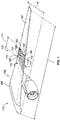
- Figure 1 illustrates a perspective top view of an aircraft assembly 100.
- the aircraft assembly 100 includes an aircraft structure 106 and an aircraft surface cover 109 that includes a cover member 110.
- the aircraft structure 106 is disposed on an exterior 104 of an aircraft 102.
- the aircraft structure 106 in the illustrated example is a wing 107 having a width W and a length L. It may be noted that the width W varies over length L.
- Other examples of aircraft structures that may be utilized in various examples include tails, flaps, or rotors (e.g., helicopter rotor blades).
- the cover member 110 is removably secured to the aircraft structure 106.
- "Removably secured” as used herein may be understood as meaning that the cover member 110 is attached as a unit to the aircraft structure 106 while not becoming an integral part of the aircraft structure 106.
- a layer that was printed on the aircraft structure 106 would not be removably secured as used herein, at least because it was not applied as a unit.
- a structure that were welded to the aircraft structure 106 would not removably secured as used herein, at least because welding would render the structure integral with the aircraft structure 106.
- a surface that was machined into the aircraft structure 106 would not be removably secured as used herein, at least because such machining would make the surface an integral part of the aircraft structure 106.
- removably secured cover members as discussed herein may be added to an aircraft structure 106 after the aircraft 102 has been assembled, and removed non-destructively with respect to the aircraft structure 106, and without adversely affecting the structural integrity of the aircraft structure 106. Further, removably secured cover members as discussed herein may be removed with minimal or no effect on the surface finish of the aircraft structure 106. For example, in some examples, remnants of adhesive may be left on the surface after removal of a removably secured cover member.
- the removal process may be non-destructive as well with respect to the cover member 110 in various examples.
- the cover member 110 may include a compressible sleeve that may be stretched for removal from the aircraft structure 106.
- the cover member 110 may be destructively removed from the aircraft structure 106, for example by cutting through the cover member 110.
- the cover member 110 includes an exterior surface 112.
- the exterior surface 112 has a microtextured surface 114.
- the microtextured surface 114 is disposed on the microtextured surface 114 and oriented toward an atmosphere surrounding the aircraft 102. Accordingly, air passes over the microtextured surface 114 as the aircraft 102 moves.
- the microtextured surface 114 includes microtexture ribs 116 that are configured to improve aerodynamic performance of the aircraft structure 106.
- the microtexture ribs 116 may be configured to improve drag and/or lift.
- the microtexture ribs 116 are separated by grooves 118.
- the microtexture ribs 116 may have a height of about 0.5 millimeters and have about 1 millimeter spacing between adjacent ribs.
- the illustrated example shows ribs extending along the entire width W, it may be noted that ribs may be shorter in other examples.
- the ribs may be regularly or irregularly spaced, as well as uniformly or non-uniformly sized.
- the microtextured surface 114 may be provided in a predetermined pattern to provide improved aerodynamic performance, and the cover member 110 secured to the aircraft structure 106 with the microtextured surface 114 oriented in the predetermined pattern.
- the microtexture ribs 116 may be configured to provide denticles or aspects of a sharkskin style surface design configured for improved aerodynamic performance.
- the cover member 110 may be configured as a sleeve that wraps around the aircraft structure 106.
- the cover member 110 may be configured as a sheet that is adhesively joined to the aircraft structure 106.
- one or more of an elastic material, heat shrinking, or adhesives may be used to secure the cover member 110 to the aircraft structure 106.
- the microtextured surface 114 is disposed on the removable cover member 110.
- a removable cover member 110 with a microtextured surface 114 disposed thereon allows for quick and convenient replacing and/or repairing of a microtextured surface 114 without requiring extensive re-work of the aircraft structure 106 itself.
- the cover member 110 may be conveniently replaced periodically at pre-determined intervals or as needed.
- the cover member 110 depicted in Figure 1 extends along the entire width W of the aircraft structure 106 at the location along the length L at which the cover member 110 is positioned.
- the cover member 110 may be understood as including or being configured as a partial cover that only extends along a portion (and not the entirety) of the width W.
- Such a partial cover may also be referred to as a bra or leading surface cover.
- Figure 2 provides a perspective view of a partial cover 210 disposed on the aircraft structure 106 in accordance with various examples.
- the partial cover 210 may be understood as an example of cover member 110, and includes microtextured ribs on an exterior surface as discussed above.
- the depicted partial cover 210 is configured (e.g., sized and shaped) to cover a leading portion 206 of the aircraft structure 106 (e.g., a portion of the aircraft structure 106 oriented toward the direction of travel). As seen in Figure 2 , the partial cover 210 does not extend along the entire width W of the aircraft structure 106. Instead, the partial cover 210 only extends along a portion 212 of the width W, resulting in a covered portion 220 and an uncovered portion 222 of the aircraft structure 106. In the example depicted in Figure 2 , the partial cover 210 includes loops 230 to help secure and/or maintain the partial cover 210 in place.
- an adhesive may be used to secure the partial cover 210 in place, for example.
- Use of a partial cover 210 allows for efficient placement of microtextured surfaces of the partial cover 210 toward a front or leading surface of the aircraft structure 106 while allowing for a relatively small cover and/or allowing access to a larger portion of the surface of the aircraft structure 106.
- the cover member includes or is configured as a sleeve that is configured (e.g., sized and shaped) to extend around a circumference of the aircraft structure.
- Figure 3 provides a cross-sectional view of a sleeve 310 disposed around a circumference 306 of an aircraft structure 106.
- the sleeve 310 may be understood as an example of the cover member 110.
- the sleeve 310 depicted in Figure 3 extends along the entire circumference 306 of the aircraft structure 106 to define a closed loop around a cross-section of the aircraft structure 106 taken at a point along its length L.
- the sleeve 310 has an upper exterior surface portion 311 and a lower exterior surface portion 312.
- a microtextured surface as discussed herein is disposed on at least one of the upper exterior surface portion 311 or lower exterior surface portion 312.
- a microtextured surface may be disposed on all or a portion of the upper exterior surface portion 311 and/or lower exterior surface portion 312.
- an upper microtextured surface 313 disposed on all or a portion of the upper exterior surface portion 311) may be configured differently than a lower microtextured surface 314 (disposed on all or a portion of the lower exterior surface portion 312) to impart different aerodynamic properties for the upper and lower surfaces.
- Use of a sleeve 310 allows for provision of microtextured surfaces over a large (or entire) portion of an aircraft structure 106.
- the sleeve 310 may be made of an elastic material.
- Figure 4 provides a side view of an elastic sleeve 400 in accordance with various examples.
- the elastic sleeve 400 of Figure 4 may be understood as an example of the sleeve 310 of Figure 3 .
- the sleeve 400 has a nominal pre-application cross-sectional area 420.
- the nominal pre-application cross-sectional area 420 is smaller than a corresponding cross-sectional area 320 (e.g., a cross-sectional area of the aircraft structure at which the cross-section of the elastic sleeve 400 will be located) of the aircraft structure 106 (see Figure 3 ). Accordingly, to place the sleeve 400 on the aircraft structure 106, the elastic sleeve 400 is stretched to increase its cross-sectional area, and pulled over an end of the aircraft structure 106 to a desired end location, at which point the elastic sleeve 400 is allowed to compress under its elasticity about the aircraft structure 106, securing the elastic sleeve 400 in place.
- a corresponding cross-sectional area 320 e.g., a cross-sectional area of the aircraft structure at which the cross-section of the elastic sleeve 400 will be located
- the elastic sleeve 400 is stretched to increase its cross-sectional area and pulled off of the aircraft structure 106. Accordingly, the elastic sleeve 400 may be conveniently placed on the aircraft structure 106 and non-destructively removed. It may be noted that the cross-sectional area of the elastic sleeve 400 may be tapered along the length L to match a taper of the cross-sectional area of the aircraft structure 106.
- the sleeve 310 may be made of a heat shrinkable material, and be applied as a pre-formed sleeve that has a slightly larger cross-sectional area than a corresponding portion of the aircraft structure 106, and is shrunk to fit the aircraft structure 106 once in place.
- the sleeve 310 may be initially formed as a sheet that is subsequently heat-shrunk onto the aircraft structure 106.
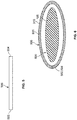
- Figures 5 and 6 provide side schematic views of a sheet 500 used to form a sleeve 310 in accordance with various examples. As seen in Figure 5 , the sheet 500 has a first edge 502 and a second edge 504 opposite the first edge 502, as well as an exterior surface 506.
- a microtextured surface as discussed herein is disposed on the exterior surface 506, and the sheet 500 is made of a heat-shrinkable material. As seen in Figure 6 , the sheet 500 is joined at an edge (e.g., first edge 502 is joined to second edge 504) after the sheet is disposed around the aircraft structure 106. A gap 600 is shown between the sheet 500 that has been formed into a sleeve 310 and the aircraft structure 106. Once the sleeve 310 is formed and in place, the sleeve 310 may be heat shrunk to be secured to the aircraft structure 106. It may be noted that the ends need not be joined to each other.
- one end could be joined to an intermediate portion of the sheet, with the portion between the intermediate portion and other end trimmed off after joining, allowing for a more close, customizable fit to a particular size or shape of aircraft structure using a pre-formed sheet.
- the gap 600 shown in Figure 6 is fairly large for ease and clarity of illustration; however, the actual gap may be sized to allow for 10% or less shrinkage.
- the sheet 500 may be configured to shrink more along one direction than one or more other directions (e.g., configured to shrink more along the width instead of the length).
- the aircraft structure 106 may have portions (e.g., projections) that are difficult or impractical to cover with a sleeve or other cover member.
- Figure 7 depicts an aircraft structure 106 with features 706 (the features are projections in the illustrated example), and a sleeve 710 that includes openings 712 configured to extend around the features 706 of the aircraft structure 106.
- the sleeve 710 may be understood as an example of the sleeve 310 and includes microtextured surfaces on at least a portion of its exterior surface.
- the openings 712 may be configured to fit around engine mounts, movable flaps, pitot tubes or other sensing devices, lights, or other features of the aircraft structure 106 that are inappropriate or inconvenient to cover.
- the cover member 110 may not cover an entire length of the aircraft structure 106.
- the cover member 110 has a length 111 that is less than the corresponding length L of the aircraft structure 106, with the cover member 110 covering only a portion of the aircraft structure 106 along the length L of the aircraft structure 106.
- the sleeve 710 of Figure 7 provides another example of a cover member that has a length that is less than the corresponding length L of the aircraft structure 106.
- the cover member 110 may cover an entire length of an aircraft structure 106 (e.g., airfoil).
- Figure 8 provides a perspective view of a helicopter blade 800 having an airfoil 802, with a cover 810 extending along the entire length 804 of the airfoil 802.
- the cover 810 may be understood as an example of the cover member 110, and includes a microtextured surface as discussed herein.
- the cover member 110 and aircraft structure 106 includes one or more locating features configured to help ensure proper positioning or placement of the cover member 110 on the aircraft structure 106.
- the cover member 110 includes a cover locating feature 190 that is configured to cooperate with a corresponding feature 192 of the aircraft structure 106 for locating the cover member 110 relative to the aircraft structure 106.
- the cover locating feature 190 and corresponding feature 192 are configured to be disposed adjacent to one another when the cover member 110 is positioned in a desired placement; however, it may be noted that other predetermined relationships may be utilized.
- the cover locating feature 190 may be configured to be placed directly over the corresponding feature 192.
- the corresponding feature 192 may be printed, painted, or applied as a decal to the aircraft structure 106 in some examples.
- an existing structural component e.g., engine mount, edge or corner of a structure, edge of a flap, or the like
- cover locating feature 190 may be used in cooperation with the cover locating feature 190.
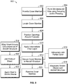
- Figure 9 illustrates a flowchart of a method 900 for improving aerodynamic performance of an aircraft structure.
- the method 900 may employ structures or aspects of various examples (e.g., systems and/or methods) discussed herein.
- certain steps may be omitted or added, certain steps may be combined, certain steps may be performed simultaneously, certain steps may be performed concurrently, certain steps may be split into multiple steps, certain steps may be performed in a different order, or certain steps or series of steps may be re-performed in an iterative fashion.
- a cover member (e.g., cover member 110) is provided.
- the cover member includes an exterior surface having a microtextured surface that includes microtexture ribs as discussed herein.
- the microtexture ribs are configured to improve the aerodynamic performance of an aircraft structure (e.g., aircraft structure 106) to which the cover member will be mounted.
- Various techniques may be employed to form the cover member, which may be formed as a sheet (e.g., sheet 500), for example, or a partial cover (e.g., partial cover 210), as another example, or a sleeve (e.g., sleeve 310) as another example.
- the cover member in various examples may be made of an elastic and/or heat-shrinkable material.
- the microtexture ribs are formed on the exterior surface of sleeve using at least one of extruding or pressing.
- the cover member is located at a predetermined position relative to the aircraft structure.
- a cover locating feature of the cover member that cooperates with a corresponding feature of the aircraft structure is used to locate the cover member at the predetermined position. Locating the cover member in a predetermined position in various examples also includes orienting microtextured protrusions (or ribs) in a predetermined pattern relative to the aircraft structure to provide improved aerodynamic performance.
- openings of the cover member are positioned around features of the aircraft structure when positioning the cover member.
- the openings may be positioned around the features when the sheet is wrapped around the circumference of the aircraft structure (e.g., to form a sleeve). It may be noted that this step may be omitted for cover members that are not placed near or around any features that are undesirable or impractical to cover.
- an intermediate filler layer may be utilized, for example, to improve fit and/or adhesion between the cover member and the aircraft structure, to ease removal of the cover member, and/or to protect the aircraft structure.
- an intermediate filler layer is applied to a surface of the aircraft structure before securing the cover member.
- the cover member is secured to the aircraft structure.
- the cover member is removably secured to the aircraft structure.
- Various techniques may be employed in various examples to secure the cover member to the aircraft structure.
- a partial cover (e.g., partial cover 210) is adhesively joined to a leading portion of the aircraft structure.
- the cover member includes or is configured as a sleeve made of an elastic material.
- the sleeve is elastically stretched over the aircraft structure, and allowed to constrict onto the aircraft structure to secure the sleeve to the aircraft structure.
- a heat-shrinkable material is used.
- a sheet is wrapped around a circumference of the aircraft structure.
- ends of the sheet are joined to each other to form a sleeve.
- heat is applied to shrink the sleeve onto the aircraft structure.
- the cover member is removably secured to the aircraft structure.
- the cover member is removed from the aircraft structure. Removal of the cover member allows for repair and/or replacement of the cover member without having to re-work any surfaces of the aircraft structure, reducing the time and cost of maintenance of a microtextured surface for an aircraft structure.
- the cover member may be removed without damaging the cover member, for example, by stretching an elastic material of the cover member to pull the cover member off of a wing or other aircraft structure to which it was mounted.
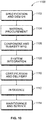
- Examples of the disclosure may be described in the context of an aircraft manufacturing and service method 1100 as shown in FIG. 10 and an aircraft 1200 as shown in FIG. 11 .
- illustrative method 1100 may include specification and design 1102 of the aircraft 1200 and material procurement 1104.
- component and subassembly manufacturing 1106 and system integration 1108 of the aircraft 1200 take place.
- the aircraft 1200 may go through certification and delivery 1110 to be placed in service 1112.
- routine maintenance and service 1114 which may also include modification, reconfiguration, refurbishment, and so on).
- Each of the processes of the illustrative method 1100 may be performed or carried out by a system integrator, a third party, and/or an operator (e.g., a customer).
- a system integrator may include, without limitation, any number of aircraft manufacturers and major-system subcontractors
- a third party may include, without limitation, any number of vendors, subcontractors, and suppliers
- an operator may be an airline, leasing company, military entity, service organization, and so on.
- the aircraft 1200 produced by the illustrative method 1100 may include an airframe 1202 with a plurality of high-level systems 1204 and an interior 1206.
- high-level systems 1204 include one or more of a propulsion system 1208, an electrical system 1210, a hydraulic system 1212, and an environmental system 1214. Any number of other systems may be included.
- an aerospace example is shown, the principles of the disclosure may be applied to other industries, such as the automotive industry. Accordingly, in addition to aircraft 1200, the principles disclosed herein may apply to other vehicles, e.g., land vehicles, marine vehicles, space vehicles, etc.
- Apparatus and methods shown or described herein may be employed during any one or more of the stages of the manufacturing and service method 1100.
- components or subassemblies corresponding to component and subassembly manufacturing 1106 may be fabricated or manufactured in a manner similar to components or subassemblies produced while the aircraft 1200 is in service.
- one or more aspects of the apparatus, method, or combination thereof may be utilized during the production stages 1106 and 1108, for example, by substantially expediting assembly of or reducing the cost of an aircraft 1200.
- one or more aspects of the apparatus or method realizations, or a combination thereof may be utilized, for example and without limitation, while the aircraft 1200 is in service, e.g., maintenance and service 1114.
- a structure, limitation, or element that is "configured to” perform a task or operation is particularly structurally formed, constructed, or adapted in a manner corresponding to the task or operation.
- an object that is merely capable of being modified to perform the task or operation is not “configured to” perform the task or operation as used herein.
Landscapes
- Engineering & Computer Science (AREA)
- Aviation & Aerospace Engineering (AREA)
- Manufacturing & Machinery (AREA)
- Transportation (AREA)
- Aiming, Guidance, Guns With A Light Source, Armor, Camouflage, And Targets (AREA)
- Lining Or Joining Of Plastics Or The Like (AREA)
- Laminated Bodies (AREA)
Abstract
Description
- Examples of the present disclosure generally relate to systems and methods for providing microtextured surfaces for aircraft structures.
- Microtextured skin patterns may be utilized on airfoil surfaces to improve aerodynamic properties (e.g., drag and/or lift). However, such skin patterns may be difficult or expensive to manufacture, install, and/or maintain.
- For example, use of machining or other means of subtracting from an airfoil surface (e.g., laser ablation, etching) may reduce durability of the airfoil, and may result in expensive and/or inconvenient repair and/or installation. As another example, techniques such as hot metal rolling or pressing may distort the surface, and also result in expensive and/or inconvenient repair and/or installation.
- It is with respect to these and other considerations that the disclosure made herein is presented.
- A need exists for an improved system and an improved method for providing microtextured surfaces to airfoil surfaces.
- With those needs in mind, certain examples of the present disclosure provide an aircraft surface cover. The aircraft surface cover includes a cover member that is configured to be removably secured to an aircraft structure. The cover member includes an exterior surface that has a microtextured surface including microtexture ribs that are configured to improve aerodynamic performance of the aircraft structure.
- Certain examples of the present disclosure provide a method of improving aerodynamic performance of an aircraft structure. The method includes providing a cover member comprising an exterior surface that has a microtextured surface. The microtextured surface includes microtexture ribs configured to improve aerodynamic performance of the aircraft structure. The method also includes securing the cover member to the aircraft structure.
- Certain examples of the present disclosure provide an aircraft assembly that includes an aircraft structure and a cover member. The aircraft structure is disposed on an exterior of an aircraft. The cover member is removably secured to the aircraft structure, and includes an exterior surface. The exterior surface has a microtextured surface that includes microtexture ribs that are configured to improve aerodynamic performance of the aircraft structure.
-
-
Figure 1 illustrates a perspective view of an aircraft assembly, according to an example of the present disclosure. -
Figure 2 provides a perspective view of a partial cover disposed on an aircraft structure, according to an example of the present disclosure. -
Figure 3 provides a cross-sectional view of a sleeve disposed around a circumference of an aircraft structure, according to an example of the present disclosure. -
Figure 4 provides a side view of an elastic sleeve, according to an example of the present disclosure. -
Figure 5 provides a side schematic view of a sheet used to form a sleeve, accordingly to an example of the present disclosure. -
Figure 6 provide side schematic view of the sheet ofFigure 5 formed into a sleeve. -
Figure 7 provides a schematic view of a sleeve, according to an example of the present disclosure. -
Figure 8 provides a schematic view of a sleeve, according to an example of the present disclosure. -
Figure 9 provides a flowchart of a method, according to an example of the present disclosure. -
Figure 10 is a block diagram of aircraft production and service methodology. -
Figure 11 is a schematic perspective view of an aircraft. - The foregoing summary, as well as the following detailed description of certain examples will be better understood when read in conjunction with the appended drawings. As used herein, an element or step recited in the singular and preceded by the word "a" or "an" should be understood as not necessarily excluding the plural of the elements or steps. Further, references to "one example" are not intended to be interpreted as excluding the existence of additional examples that also incorporate the recited features. Moreover, unless explicitly stated to the contrary, examples "comprising" or "having" an element or a plurality of elements having a particular condition may include additional elements not having that condition.
- Examples of the present disclosure provide systems, methods, and assemblies for applying a microtextured pattern to an outer surface of an aircraft (e.g., wing surface) without requiring extensive work to the surface. Various examples provide a removably secured cover member to provide the microtextured surface. Various examples provide a sleeve or other cover that may be replaced throughout the service life of the aircraft without extensive rework of the surface, conveniently and effectively providing improved aerodynamic performance.
-
Figure 1 illustrates a perspective top view of anaircraft assembly 100. Theaircraft assembly 100 includes anaircraft structure 106 and anaircraft surface cover 109 that includes acover member 110. Theaircraft structure 106 is disposed on anexterior 104 of anaircraft 102. For example, theaircraft structure 106 in the illustrated example is awing 107 having a width W and a length L. It may be noted that the width W varies over length L. Other examples of aircraft structures that may be utilized in various examples include tails, flaps, or rotors (e.g., helicopter rotor blades). - The
cover member 110 is removably secured to theaircraft structure 106. "Removably secured" as used herein may be understood as meaning that thecover member 110 is attached as a unit to theaircraft structure 106 while not becoming an integral part of theaircraft structure 106. By way of example, and for the purposes of clarity, a layer that was printed on theaircraft structure 106 would not be removably secured as used herein, at least because it was not applied as a unit. As another example, and for the purposes of clarity, a structure that were welded to theaircraft structure 106 would not removably secured as used herein, at least because welding would render the structure integral with theaircraft structure 106. As one more example for the purposes of clarity, a surface that was machined into theaircraft structure 106 would not be removably secured as used herein, at least because such machining would make the surface an integral part of theaircraft structure 106. Generally, removably secured cover members as discussed herein may be added to anaircraft structure 106 after theaircraft 102 has been assembled, and removed non-destructively with respect to theaircraft structure 106, and without adversely affecting the structural integrity of theaircraft structure 106. Further, removably secured cover members as discussed herein may be removed with minimal or no effect on the surface finish of theaircraft structure 106. For example, in some examples, remnants of adhesive may be left on the surface after removal of a removably secured cover member. It may be noted that the removal process may be non-destructive as well with respect to thecover member 110 in various examples. For example, thecover member 110 may include a compressible sleeve that may be stretched for removal from theaircraft structure 106. Alternatively, in other examples, thecover member 110 may be destructively removed from theaircraft structure 106, for example by cutting through thecover member 110. - The
cover member 110 includes anexterior surface 112. Theexterior surface 112 has amicrotextured surface 114. Themicrotextured surface 114 is disposed on themicrotextured surface 114 and oriented toward an atmosphere surrounding theaircraft 102. Accordingly, air passes over themicrotextured surface 114 as theaircraft 102 moves. Themicrotextured surface 114 includesmicrotexture ribs 116 that are configured to improve aerodynamic performance of theaircraft structure 106. For example, themicrotexture ribs 116 may be configured to improve drag and/or lift. In the illustrated example, themicrotexture ribs 116 are separated bygrooves 118. In various examples, themicrotexture ribs 116 may have a height of about 0.5 millimeters and have about 1 millimeter spacing between adjacent ribs. While the illustrated example shows ribs extending along the entire width W, it may be noted that ribs may be shorter in other examples. In various examples, the ribs may be regularly or irregularly spaced, as well as uniformly or non-uniformly sized. Generally, themicrotextured surface 114 may be provided in a predetermined pattern to provide improved aerodynamic performance, and thecover member 110 secured to theaircraft structure 106 with themicrotextured surface 114 oriented in the predetermined pattern. In various examples, themicrotexture ribs 116 may be configured to provide denticles or aspects of a sharkskin style surface design configured for improved aerodynamic performance. - As also discussed elsewhere herein, a variety of techniques may be used to mount or secure the
cover member 110 to theaircraft structure 106. For example, thecover member 110 may be configured as a sleeve that wraps around theaircraft structure 106. As another example, thecover member 110 may be configured as a sheet that is adhesively joined to theaircraft structure 106. In various examples, one or more of an elastic material, heat shrinking, or adhesives may be used to secure thecover member 110 to theaircraft structure 106. - Accordingly, instead of being formed integrally with or permanently attached to the
aircraft structure 106, themicrotextured surface 114 is disposed on theremovable cover member 110. Use of aremovable cover member 110 with amicrotextured surface 114 disposed thereon allows for quick and convenient replacing and/or repairing of amicrotextured surface 114 without requiring extensive re-work of theaircraft structure 106 itself. Thecover member 110 may be conveniently replaced periodically at pre-determined intervals or as needed. - It may be noted that the
cover member 110 depicted inFigure 1 extends along the entire width W of theaircraft structure 106 at the location along the length L at which thecover member 110 is positioned. However, in other examples, thecover member 110 may be understood as including or being configured as a partial cover that only extends along a portion (and not the entirety) of the width W. Such a partial cover may also be referred to as a bra or leading surface cover.Figure 2 provides a perspective view of apartial cover 210 disposed on theaircraft structure 106 in accordance with various examples. Thepartial cover 210 may be understood as an example ofcover member 110, and includes microtextured ribs on an exterior surface as discussed above. As seen inFigure 2 , the depictedpartial cover 210 is configured (e.g., sized and shaped) to cover a leadingportion 206 of the aircraft structure 106 (e.g., a portion of theaircraft structure 106 oriented toward the direction of travel). As seen inFigure 2 , thepartial cover 210 does not extend along the entire width W of theaircraft structure 106. Instead, thepartial cover 210 only extends along aportion 212 of the width W, resulting in a coveredportion 220 and anuncovered portion 222 of theaircraft structure 106. In the example depicted inFigure 2 , thepartial cover 210 includesloops 230 to help secure and/or maintain thepartial cover 210 in place. Alternatively or additionally, an adhesive may be used to secure thepartial cover 210 in place, for example. Use of apartial cover 210 allows for efficient placement of microtextured surfaces of thepartial cover 210 toward a front or leading surface of theaircraft structure 106 while allowing for a relatively small cover and/or allowing access to a larger portion of the surface of theaircraft structure 106. - In various examples, the cover member includes or is configured as a sleeve that is configured (e.g., sized and shaped) to extend around a circumference of the aircraft structure.
Figure 3 provides a cross-sectional view of asleeve 310 disposed around acircumference 306 of anaircraft structure 106. Thesleeve 310 may be understood as an example of thecover member 110. As seen inFigure 3 , in contrast to thepartial cover 210 ofFigure 2 , thesleeve 310 depicted inFigure 3 extends along theentire circumference 306 of theaircraft structure 106 to define a closed loop around a cross-section of theaircraft structure 106 taken at a point along its length L. It may be noted that thesleeve 310 has an upperexterior surface portion 311 and a lowerexterior surface portion 312. A microtextured surface as discussed herein is disposed on at least one of the upperexterior surface portion 311 or lowerexterior surface portion 312. In various examples, a microtextured surface may be disposed on all or a portion of the upperexterior surface portion 311 and/or lowerexterior surface portion 312. It may be noted that in various examples an upper microtextured surface 313 (disposed on all or a portion of the upper exterior surface portion 311) may be configured differently than a lower microtextured surface 314 (disposed on all or a portion of the lower exterior surface portion 312) to impart different aerodynamic properties for the upper and lower surfaces. Use of asleeve 310 allows for provision of microtextured surfaces over a large (or entire) portion of anaircraft structure 106. - In various examples, the
sleeve 310 may be made of an elastic material.Figure 4 provides a side view of anelastic sleeve 400 in accordance with various examples. Theelastic sleeve 400 ofFigure 4 may be understood as an example of thesleeve 310 ofFigure 3 . As seen inFigure 4 , in which thesleeve 400 is shown in an unstretched condition, thesleeve 400 has a nominal pre-applicationcross-sectional area 420. The nominal pre-applicationcross-sectional area 420 is smaller than a corresponding cross-sectional area 320 (e.g., a cross-sectional area of the aircraft structure at which the cross-section of theelastic sleeve 400 will be located) of the aircraft structure 106 (seeFigure 3 ). Accordingly, to place thesleeve 400 on theaircraft structure 106, theelastic sleeve 400 is stretched to increase its cross-sectional area, and pulled over an end of theaircraft structure 106 to a desired end location, at which point theelastic sleeve 400 is allowed to compress under its elasticity about theaircraft structure 106, securing theelastic sleeve 400 in place. To remove theelastic sleeve 400, theelastic sleeve 400 is stretched to increase its cross-sectional area and pulled off of theaircraft structure 106. Accordingly, theelastic sleeve 400 may be conveniently placed on theaircraft structure 106 and non-destructively removed. It may be noted that the cross-sectional area of theelastic sleeve 400 may be tapered along the length L to match a taper of the cross-sectional area of theaircraft structure 106. - In various examples, the
sleeve 310 may be made of a heat shrinkable material, and be applied as a pre-formed sleeve that has a slightly larger cross-sectional area than a corresponding portion of theaircraft structure 106, and is shrunk to fit theaircraft structure 106 once in place. In other examples, thesleeve 310 may be initially formed as a sheet that is subsequently heat-shrunk onto theaircraft structure 106. For example,Figures 5 and 6 provide side schematic views of asheet 500 used to form asleeve 310 in accordance with various examples. As seen inFigure 5 , thesheet 500 has afirst edge 502 and asecond edge 504 opposite thefirst edge 502, as well as anexterior surface 506. A microtextured surface as discussed herein is disposed on theexterior surface 506, and thesheet 500 is made of a heat-shrinkable material. As seen inFigure 6 , thesheet 500 is joined at an edge (e.g.,first edge 502 is joined to second edge 504) after the sheet is disposed around theaircraft structure 106. Agap 600 is shown between thesheet 500 that has been formed into asleeve 310 and theaircraft structure 106. Once thesleeve 310 is formed and in place, thesleeve 310 may be heat shrunk to be secured to theaircraft structure 106. It may be noted that the ends need not be joined to each other. For example, one end could be joined to an intermediate portion of the sheet, with the portion between the intermediate portion and other end trimmed off after joining, allowing for a more close, customizable fit to a particular size or shape of aircraft structure using a pre-formed sheet. It may be noted that thegap 600 shown inFigure 6 is fairly large for ease and clarity of illustration; however, the actual gap may be sized to allow for 10% or less shrinkage. Further, in various examples, thesheet 500 may be configured to shrink more along one direction than one or more other directions (e.g., configured to shrink more along the width instead of the length). - It may be noted that in various examples, the
aircraft structure 106 may have portions (e.g., projections) that are difficult or impractical to cover with a sleeve or other cover member. For example,Figure 7 depicts anaircraft structure 106 with features 706 (the features are projections in the illustrated example), and asleeve 710 that includesopenings 712 configured to extend around thefeatures 706 of theaircraft structure 106. Thesleeve 710 may be understood as an example of thesleeve 310 and includes microtextured surfaces on at least a portion of its exterior surface. Theopenings 712 may be configured to fit around engine mounts, movable flaps, pitot tubes or other sensing devices, lights, or other features of theaircraft structure 106 that are inappropriate or inconvenient to cover. - In various examples, the cover member 110 (e.g., sleeve 310) may not cover an entire length of the
aircraft structure 106. For example, for the example illustrated inFigure 1 , thecover member 110 has alength 111 that is less than the corresponding length L of theaircraft structure 106, with thecover member 110 covering only a portion of theaircraft structure 106 along the length L of theaircraft structure 106. Thesleeve 710 ofFigure 7 provides another example of a cover member that has a length that is less than the corresponding length L of theaircraft structure 106. - It may be noted that in other examples, the
cover member 110 may cover an entire length of an aircraft structure 106 (e.g., airfoil). For example,Figure 8 provides a perspective view of ahelicopter blade 800 having anairfoil 802, with acover 810 extending along theentire length 804 of theairfoil 802. Thecover 810 may be understood as an example of thecover member 110, and includes a microtextured surface as discussed herein. - It may further be noted that in various examples one or both of the
cover member 110 andaircraft structure 106 includes one or more locating features configured to help ensure proper positioning or placement of thecover member 110 on theaircraft structure 106. For example, as seen inFigure 1 , thecover member 110 includes acover locating feature 190 that is configured to cooperate with acorresponding feature 192 of theaircraft structure 106 for locating thecover member 110 relative to theaircraft structure 106. In the illustrated example, thecover locating feature 190 andcorresponding feature 192 are configured to be disposed adjacent to one another when thecover member 110 is positioned in a desired placement; however, it may be noted that other predetermined relationships may be utilized. For example, thecover locating feature 190 may be configured to be placed directly over thecorresponding feature 192. It may be noted that thecorresponding feature 192 may be printed, painted, or applied as a decal to theaircraft structure 106 in some examples. Alternatively or additionally, an existing structural component (e.g., engine mount, edge or corner of a structure, edge of a flap, or the like) of theaircraft structure 106 may be used in cooperation with thecover locating feature 190. -
Figure 9 illustrates a flowchart of amethod 900 for improving aerodynamic performance of an aircraft structure. Themethod 900, for example, may employ structures or aspects of various examples (e.g., systems and/or methods) discussed herein. In various examples, certain steps (or operations) may be omitted or added, certain steps may be combined, certain steps may be performed simultaneously, certain steps may be performed concurrently, certain steps may be split into multiple steps, certain steps may be performed in a different order, or certain steps or series of steps may be re-performed in an iterative fashion. - At 902, a cover member (e.g., cover member 110) is provided. The cover member includes an exterior surface having a microtextured surface that includes microtexture ribs as discussed herein. The microtexture ribs are configured to improve the aerodynamic performance of an aircraft structure (e.g., aircraft structure 106) to which the cover member will be mounted. Various techniques may be employed to form the cover member, which may be formed as a sheet (e.g., sheet 500), for example, or a partial cover (e.g., partial cover 210), as another example, or a sleeve (e.g., sleeve 310) as another example. The cover member in various examples may be made of an elastic and/or heat-shrinkable material. In the illustrated example, at 904, the microtexture ribs are formed on the exterior surface of sleeve using at least one of extruding or pressing.
- At 906 of the illustrated example, the cover member is located at a predetermined position relative to the aircraft structure. In various examples, a cover locating feature of the cover member that cooperates with a corresponding feature of the aircraft structure is used to locate the cover member at the predetermined position. Locating the cover member in a predetermined position in various examples also includes orienting microtextured protrusions (or ribs) in a predetermined pattern relative to the aircraft structure to provide improved aerodynamic performance.
- At 908, openings of the cover member are positioned around features of the aircraft structure when positioning the cover member. For example, in examples utilizing a sheet, the openings may be positioned around the features when the sheet is wrapped around the circumference of the aircraft structure (e.g., to form a sleeve). It may be noted that this step may be omitted for cover members that are not placed near or around any features that are undesirable or impractical to cover.
- In some examples, an intermediate filler layer may be utilized, for example, to improve fit and/or adhesion between the cover member and the aircraft structure, to ease removal of the cover member, and/or to protect the aircraft structure. In the illustrated example, at 910, an intermediate filler layer is applied to a surface of the aircraft structure before securing the cover member.
- At 912, the cover member is secured to the aircraft structure. As discussed herein, in various examples, the cover member is removably secured to the aircraft structure. Various techniques may be employed in various examples to secure the cover member to the aircraft structure.
- For example, in some examples, at 914, a partial cover (e.g., partial cover 210) is adhesively joined to a leading portion of the aircraft structure.
- As another example, in some examples the cover member includes or is configured as a sleeve made of an elastic material. For such a sleeve, at 916, the sleeve is elastically stretched over the aircraft structure, and allowed to constrict onto the aircraft structure to secure the sleeve to the aircraft structure.
- As another example, in some examples, a heat-shrinkable material is used. For example, at 918, a sheet is wrapped around a circumference of the aircraft structure. At 920, ends of the sheet are joined to each other to form a sleeve. At 922, heat is applied to shrink the sleeve onto the aircraft structure.
- As noted herein, in various examples, the cover member is removably secured to the aircraft structure. For example, in the illustrated example, at 924, the cover member is removed from the aircraft structure. Removal of the cover member allows for repair and/or replacement of the cover member without having to re-work any surfaces of the aircraft structure, reducing the time and cost of maintenance of a microtextured surface for an aircraft structure. In some examples, the cover member may be removed without damaging the cover member, for example, by stretching an elastic material of the cover member to pull the cover member off of a wing or other aircraft structure to which it was mounted.
- Examples of the disclosure may be described in the context of an aircraft manufacturing and
service method 1100 as shown inFIG. 10 and anaircraft 1200 as shown inFIG. 11 . During pre-production,illustrative method 1100 may include specification anddesign 1102 of theaircraft 1200 andmaterial procurement 1104. During production, component andsubassembly manufacturing 1106 andsystem integration 1108 of theaircraft 1200 take place. Thereafter, theaircraft 1200 may go through certification anddelivery 1110 to be placed inservice 1112. While in service by a customer, theaircraft 1200 is scheduled for routine maintenance and service 1114 (which may also include modification, reconfiguration, refurbishment, and so on). - Each of the processes of the
illustrative method 1100 may be performed or carried out by a system integrator, a third party, and/or an operator (e.g., a customer). For the purposes of this description, a system integrator may include, without limitation, any number of aircraft manufacturers and major-system subcontractors; a third party may include, without limitation, any number of vendors, subcontractors, and suppliers; and an operator may be an airline, leasing company, military entity, service organization, and so on. - As shown in
FIG. 11 , theaircraft 1200 produced by theillustrative method 1100 may include anairframe 1202 with a plurality of high-level systems 1204 and an interior 1206. Examples of high-level systems 1204 include one or more of apropulsion system 1208, anelectrical system 1210, ahydraulic system 1212, and anenvironmental system 1214. Any number of other systems may be included. Although an aerospace example is shown, the principles of the disclosure may be applied to other industries, such as the automotive industry. Accordingly, in addition toaircraft 1200, the principles disclosed herein may apply to other vehicles, e.g., land vehicles, marine vehicles, space vehicles, etc. - Apparatus and methods shown or described herein may be employed during any one or more of the stages of the manufacturing and
service method 1100. For example, components or subassemblies corresponding to component andsubassembly manufacturing 1106 may be fabricated or manufactured in a manner similar to components or subassemblies produced while theaircraft 1200 is in service. Also, one or more aspects of the apparatus, method, or combination thereof may be utilized during theproduction stages aircraft 1200. Similarly, one or more aspects of the apparatus or method realizations, or a combination thereof, may be utilized, for example and without limitation, while theaircraft 1200 is in service, e.g., maintenance andservice 1114. - Further, the disclosure comprises examples according to the following clauses:
- 1. An aircraft surface cover (109) comprising:
a cover member (110) configured to be removably secured to an aircraft structure (106), the cover member (110) comprising an exterior surface (112), the exterior surface (112) having a microtextured surface (114) comprising microtexture ribs (116) configured to improve aerodynamic performance of the aircraft structure (106). - 2. The aircraft surface cover (109) of Clause 1, wherein the cover member (110) comprises a partial cover (210) configured to cover a leading portion (206) of the aircraft structure (106), the partial cover (210) configured to be adhesively joined to the aircraft structure (106).
- 3. The aircraft surface cover (109) of Clause 1, wherein the cover member (110) comprises a sleeve (310) configured to extend around a circumference (306) of the aircraft structure (106).
- 4. The aircraft surface cover (109) of Clause 3, wherein the sleeve (310) is made of an elastic material, the sleeve (310) having a nominal pre-application cross-sectional area (420) that is smaller than a corresponding cross-sectional area (320) of the aircraft structure (106).
- 5. The aircraft surface cover (109) of Clause 3, wherein the sleeve (310) is made of a heat-shrinkable material, wherein the sleeve (310) comprises a sheet (500) configured to be joined at an edge when disposed around the aircraft structure (106).
- 6. The aircraft surface cover (109) according to any of Clauses 3 to 5, wherein the sleeve (310) includes openings (712) configured to extend around features (706) of the aircraft structure (106).
- 7. The aircraft surface cover (109) according to any of Clauses 3 to 6, wherein the sleeve (310) has a length (111) that is less than a corresponding length (111) of the aircraft structure (106), wherein the sleeve (310) is configured to cover only a portion (206) of the aircraft structure (106).
- 8. The aircraft surface cover (109) according to any of the preceding Clauses, further comprising a cover locating feature configured to cooperate with a corresponding feature (192) of the aircraft structure (106) for locating the cover member (110) relative to the aircraft structure (106).
- 9. A method of improving aerodynamic performance of an aircraft structure (106), the method comprising:
- providing a cover member (110) comprising an exterior surface (112), the exterior surface (112) having a microtextured surface (114) comprising microtexture ribs (116) configured to improve aerodynamic performance of the aircraft structure (106); and
- securing the cover member (110) to the aircraft structure (106).
- 10. The method of Clause 9, wherein securing the cover member (110) comprises adhesively joining a partial cover (210) to a leading portion (206) of the aircraft structure (106).
- 11. The method of Clause 9, wherein the cover member (110) comprises a sleeve (310) made of an elastic material, wherein securing the cover member (110) comprises elastically stretching the sleeve (310) over the aircraft structure (106), and allowing the sleeve (310) to constrict onto the aircraft structure (106).
- 12. The method of Clause 9, wherein the cover member (110) comprises a sheet (500) of heat-shrinkable material, wherein securing the cover member (110) comprises:
- wrapping the sheet (500) around a circumference (306) of the aircraft structure (106);
- joining ends of the sheet (500) to each other to form a sleeve (310); and
- applying heat to shrink the sleeve (310) onto the aircraft structure (106).
- 13. The method of any of Clauses 11 or 12, further comprising positioning openings (712) of the sleeve (310) around features (706) of the aircraft structure (106) when wrapping the sheet (500) around the circumference (306) of the aircraft structure (106).
- 14. The method according to any of Clauses 9 to 13, further comprising locating the cover member (110) at a predetermined position relative to the aircraft structure (106) via a cover locating feature that cooperates with a corresponding feature (192) of the aircraft structure (106).
- 15. The method according to any of Clauses 9 to 14, further comprising removing the cover member (110) from the aircraft structure (106).
- 16. The method according to any of Clauses 9 to 15, further comprising applying an intermediate filler layer to a surface (114) of the aircraft structure (106) before securing the cover member (110).
- 17. The method according to any of Clauses 11 to 13, further comprising forming the microtexture ribs (116) on the exterior surface (112) of the sleeve (310) using at least one of extruding or pressing.
- 18. An aircraft assembly (102) comprising:
- an aircraft structure (106) disposed on an exterior (104) of an aircraft (102); and
- a cover member (110) removably secured to the aircraft structure (106), the cover member (110) comprising an exterior surface (112), the exterior surface (112) having a microtextured surface (114) comprising microtexture ribs (116) configured to improve aerodynamic performance of the aircraft structure (106).
- 19. The aircraft assembly (102) of Clause 18, wherein the cover member (110) comprises a partial cover (210) that covers a leading portion (206) of the aircraft structure (106).
- 20. The aircraft assembly (102) of Clause 18, wherein the cover member (110) comprises a sleeve (310) extending around a circumference (306) of the aircraft structure (106).
- While various spatial and directional terms, such as top, bottom, lower, mid, lateral, horizontal, vertical, front and the like may be used to describe examples of the present disclosure, it is understood that such terms are merely used with respect to the orientations shown in the drawings. The orientations may be inverted, rotated, or otherwise changed, such that an upper portion is a lower portion, and vice versa, horizontal becomes vertical, and the like.
- As used herein, a structure, limitation, or element that is "configured to" perform a task or operation is particularly structurally formed, constructed, or adapted in a manner corresponding to the task or operation. For purposes of clarity and the avoidance of doubt, an object that is merely capable of being modified to perform the task or operation is not "configured to" perform the task or operation as used herein.
- It is to be understood that the above description is intended to be illustrative, and not restrictive. For example, the above-described examples (and/or aspects thereof) may be used in combination with each other. In addition, many modifications may be made to adapt a particular situation or material to the teachings of the various examples of the disclosure without departing from their scope. While the dimensions and types of materials described herein are intended to define the parameters of the various examples of the disclosure, the examples are by no means limiting and are exemplary examples. Many other examples will be apparent to those of skill in the art upon reviewing the above description. The scope of the various examples of the disclosure should, therefore, be determined with reference to the appended claims, along with the full scope of equivalents to which such claims are entitled. In the appended claims, the terms "including" and "in which" are used as the plain-English equivalents of the respective terms "comprising" and "wherein." Moreover, the terms "first," "second," and "third," etc. are used merely as labels, and are not intended to impose numerical requirements on their objects.
- This written description uses examples to disclose the various examples of the disclosure, including the best mode, and also to enable any person skilled in the art to practice the various examples of the disclosure, including making and using any devices or systems and performing any incorporated methods. The patentable scope of the various examples of the disclosure is defined by the claims, and may include other examples that occur to those skilled in the art. Such other examples are intended to be within the scope of the claims if the examples have structural elements that do not differ from the literal language of the claims, or if the examples include equivalent structural elements with insubstantial differences from the literal language of the claims.
Claims (16)
- An aircraft surface cover (109) comprising:
a cover member (110) configured to be removably secured to an aircraft structure (106), the cover member (110) comprising an exterior surface (112), the exterior surface (112) having a microtextured surface (114) comprising microtexture ribs (116) configured to improve aerodynamic performance of the aircraft structure (106). - The aircraft surface cover (109) of Claim 1, wherein the cover member (110) comprises a partial cover (210) configured to cover a leading portion (206) of the aircraft structure (106), the partial cover (210) configured to be adhesively joined to the aircraft structure (106).
- The aircraft surface cover (109) of Claim 1, wherein the cover member (110) comprises a sleeve (310) configured to extend around a circumference (306) of the aircraft structure (106).
- The aircraft surface cover (109) of Claim 3, wherein the sleeve (310) is made of an elastic material, the sleeve (310) having a nominal pre-application cross-sectional area (420) that is smaller than a corresponding cross-sectional area (320) of the aircraft structure (106).
- The aircraft surface cover (109) of Claim 3, wherein the sleeve (310) is made of a heat-shrinkable material, wherein the sleeve (310) comprises a sheet (500) configured to be joined at an edge when disposed around the aircraft structure (106).
- The aircraft surface cover (109) according to any of Claims 3 to 5, wherein the sleeve (310) includes openings (712) configured to extend around features (706) of the aircraft structure (106), and wherein the sleeve has a length (111) that is less than a corresponding length (111) of the aircraft structure, wherein the sleeve is configured to cover only a portion (206) of the aircraft structure (106).
- The aircraft surface cover (109) according to any of the preceding Claims, further comprising a cover locating feature configured to cooperate with a corresponding feature (192) of the aircraft structure (106) for locating the cover member (110) relative to the aircraft structure (106).
- A method of improving aerodynamic performance of an aircraft structure (106), the method comprising:providing a cover member (110) comprising an exterior surface (112), the exterior surface (112) having a microtextured surface (114) comprising microtexture ribs (116) configured to improve aerodynamic performance of the aircraft structure (106); andsecuring the cover member (110) to the aircraft structure (106).
- The method of Claim 8, wherein securing the cover member (110) comprises adhesively joining a partial cover (210) to a leading portion (206) of the aircraft structure (106).
- The method of Claim 8, wherein the cover member (110) comprises a sleeve (310) made of an elastic material, wherein securing the cover member (110) comprises elastically stretching the sleeve (310) over the aircraft structure (106), and allowing the sleeve (310) to constrict onto the aircraft structure (106).
- The method of Claim 8, wherein the cover member (110) comprises a sheet (500) of heat-shrinkable material, and wherein securing the cover member (110) comprises:wrapping the sheet (500) around a circumference (306) of the aircraft structure (106);joining ends of the sheet (500) to each other to form a sleeve (310); and applying heat to shrink the sleeve (310) onto the aircraft structure (106).
- The method of any of Claims 10 or 11, further comprising positioning openings (712) of the sleeve (310) around features (706) of the aircraft structure (106) when wrapping the sheet (500) around the circumference (306) of the aircraft structure (106).
- The method according to any of Claims 8 to 12, further comprising locating the cover member (110) at a predetermined position relative to the aircraft structure (106) via a cover locating feature that cooperates with a corresponding feature (192) of the aircraft structure (106).
- The method according to any of Claims 8 to 13, further comprising removing the cover member (110) from the aircraft structure (106).
- The method according to any of Claims 8 to 14, further comprising applying an intermediate filler layer to a surface (114) of the aircraft structure (106) before securing the cover member (110).
- The method according to any of Claims 10 to 12, further comprising forming the microtexture ribs (116) on the exterior surface (112) of the sleeve (310) using at least one of extruding or pressing.
Applications Claiming Priority (1)
| Application Number | Priority Date | Filing Date | Title |
|---|---|---|---|
| US16/254,101 US11279468B2 (en) | 2019-01-22 | 2019-01-22 | Systems and methods for aircraft structure surface covers |
Publications (2)
| Publication Number | Publication Date |
|---|---|
| EP3686105A1 true EP3686105A1 (en) | 2020-07-29 |
| EP3686105B1 EP3686105B1 (en) | 2022-10-05 |
Family
ID=69174359
Family Applications (1)
| Application Number | Title | Priority Date | Filing Date |
|---|---|---|---|
| EP20152153.1A Active EP3686105B1 (en) | 2019-01-22 | 2020-01-16 | Systems and methods for aircraft structure surface covers |
Country Status (3)
| Country | Link |
|---|---|
| US (1) | US11279468B2 (en) |
| EP (1) | EP3686105B1 (en) |
| CN (1) | CN111452957B (en) |
Families Citing this family (1)
| Publication number | Priority date | Publication date | Assignee | Title |
|---|---|---|---|---|
| DE102019132344A1 (en) * | 2019-11-28 | 2021-06-02 | Lufthansa Technik Aktiengesellschaft | Device for the application of aerodynamically functional foils and their use |
Citations (6)
| Publication number | Priority date | Publication date | Assignee | Title |
|---|---|---|---|---|
| EP0205289A1 (en) * | 1985-05-31 | 1986-12-17 | Minnesota Mining And Manufacturing Company | Drag reduction article |
| US20130062004A1 (en) * | 2007-12-12 | 2013-03-14 | The Boeing Company | Aerodynamic surfaces having drag-reducing riblets and method of fabricating the same |
| DE102013102164A1 (en) * | 2013-03-05 | 2014-09-11 | Airbus Operations Gmbh | A method of coating a surface of an aircraft and an aircraft coated therewith |
| US20160325824A1 (en) * | 2015-05-06 | 2016-11-10 | The Boeing Company | Color applications for aerodynamic microstructures |
| US20180016028A1 (en) * | 2013-06-06 | 2018-01-18 | The Boeing Company | Heating Layer For Film Removal |
| US20180266388A1 (en) * | 2017-03-15 | 2018-09-20 | General Electric Company | Blade Sleeve for a Wind Turbine Rotor Blade and Attachment Methods Thereof |
Family Cites Families (21)
| Publication number | Priority date | Publication date | Assignee | Title |
|---|---|---|---|---|
| US3065940A (en) | 1956-06-22 | 1962-11-27 | Emil L Eckstein | Aircraft outer surface covering |
| US5133516A (en) * | 1985-05-31 | 1992-07-28 | Minnesota Mining And Manufacturing Co. | Drag reduction article |
| US5486096A (en) * | 1994-06-30 | 1996-01-23 | United Technologies Corporation | Erosion resistant surface protection |
| US6516652B1 (en) * | 1999-06-08 | 2003-02-11 | Cortana Corporation | Design of viscoelastic coatings to reduce turbulent friction drag |
| US7070850B2 (en) * | 2002-12-31 | 2006-07-04 | 3M Innovative Properties Company | Drag reduction article and method of use |
| WO2010017289A1 (en) | 2008-08-05 | 2010-02-11 | Alcoa Inc. | Metal sheets and plates having friction-reducing textured surfaces and methods of manufacturing same |
| US10352171B2 (en) * | 2008-11-01 | 2019-07-16 | Alexander J. Shelman-Cohen | Reduced drag system for windmills, fans, propellers, airfoils, and hydrofoils |
| US20100219296A1 (en) | 2008-11-01 | 2010-09-02 | Alexander J. Shelman-Cohen | Reduced drag system for windmills, fans, propellers, airfoils, and hydrofoils |
| US8668166B2 (en) | 2009-01-29 | 2014-03-11 | The Boeing Company | Shape memory riblets |
| US8413928B2 (en) * | 2009-09-25 | 2013-04-09 | The Boeing Company | Structurally designed aerodynamic riblets |
| US20110186685A1 (en) * | 2010-02-02 | 2011-08-04 | The Boeing Company | Thin-Film Composite Having Drag-Reducing Riblets and Method of Making the Same |
| US20140272237A1 (en) * | 2013-03-15 | 2014-09-18 | Prc-Desoto International, Inc. | Strippable film assembly and coating for drag reduction |
| US9465127B2 (en) * | 2013-05-07 | 2016-10-11 | Pgs Geophysical As | Disposable antifouling covers for geophysical survey equipment |
| US9199741B2 (en) * | 2014-03-07 | 2015-12-01 | The Boeing Company | Systems and methods for passive deicing |
| US20150284058A1 (en) * | 2014-04-08 | 2015-10-08 | Florida Institute of Technology, Inc. | Anti-biofouling, fluid dynamic efficient surface covering for structures and method of manufacturing |
| US9868135B2 (en) * | 2015-05-06 | 2018-01-16 | The Boeing Company | Aerodynamic microstructures having sub-microstructures |
| FR3050136B1 (en) * | 2016-04-13 | 2018-12-07 | Safran | MOLD AND METHOD FOR PRODUCING AERODYNAMIC ELEMENT COMPRISING RIBLETS |
| EP3472046B1 (en) * | 2016-06-20 | 2022-04-27 | 3M Innovative Properties Company | Aerodynamic articles and methods thereof |
| US10105877B2 (en) * | 2016-07-08 | 2018-10-23 | The Boeing Company | Multilayer riblet applique and methods of producing the same |
| DE102017206968B4 (en) * | 2017-04-26 | 2019-10-10 | 4Jet Microtech Gmbh & Co. Kg | Method and device for producing riblets |
| DE102017118257A1 (en) * | 2017-08-10 | 2019-02-14 | Airbus Operations Gmbh | Riblet film for air resistance reduction of aircraft |
-
2019
- 2019-01-22 US US16/254,101 patent/US11279468B2/en active Active
-
2020
- 2020-01-16 EP EP20152153.1A patent/EP3686105B1/en active Active
- 2020-01-21 CN CN202010072082.6A patent/CN111452957B/en active Active
Patent Citations (6)
| Publication number | Priority date | Publication date | Assignee | Title |
|---|---|---|---|---|
| EP0205289A1 (en) * | 1985-05-31 | 1986-12-17 | Minnesota Mining And Manufacturing Company | Drag reduction article |
| US20130062004A1 (en) * | 2007-12-12 | 2013-03-14 | The Boeing Company | Aerodynamic surfaces having drag-reducing riblets and method of fabricating the same |
| DE102013102164A1 (en) * | 2013-03-05 | 2014-09-11 | Airbus Operations Gmbh | A method of coating a surface of an aircraft and an aircraft coated therewith |
| US20180016028A1 (en) * | 2013-06-06 | 2018-01-18 | The Boeing Company | Heating Layer For Film Removal |
| US20160325824A1 (en) * | 2015-05-06 | 2016-11-10 | The Boeing Company | Color applications for aerodynamic microstructures |
| US20180266388A1 (en) * | 2017-03-15 | 2018-09-20 | General Electric Company | Blade Sleeve for a Wind Turbine Rotor Blade and Attachment Methods Thereof |
Also Published As
| Publication number | Publication date |
|---|---|
| EP3686105B1 (en) | 2022-10-05 |
| US20200231272A1 (en) | 2020-07-23 |
| US11279468B2 (en) | 2022-03-22 |
| CN111452957B (en) | 2024-12-06 |
| CN111452957A (en) | 2020-07-28 |
Similar Documents
| Publication | Publication Date | Title |
|---|---|---|
| EP4234219B1 (en) | Structural rework of cellular core panels | |
| US7998392B2 (en) | Method for manufacturing and attachment of wing fairings | |
| EP3875256B1 (en) | Method and system for manufacturing a cured composite structure | |
| EP2821210A1 (en) | Vacuum bag processing of composite parts using a conformable vacuum bag assembly | |
| EP2865847A1 (en) | Method and apparatus for supporting blades | |
| US11279468B2 (en) | Systems and methods for aircraft structure surface covers | |
| US10300653B2 (en) | Formation of thermoplastic parts | |
| US10040536B2 (en) | Wing structure, stringer structure, and related apparatus and methods of assembly | |
| US9090026B2 (en) | Method of splicing composite core | |
| US10800507B2 (en) | Panel for a vehicle and method of manufacturing a panel | |
| CA3042602C (en) | Method for co-curing perpendicular stiffeners | |
| US11673644B2 (en) | Composite spars with integrated sacrificial surfaces | |
| EP3249163B1 (en) | System and method for nose cone edge delamination repair | |
| EP3296086A1 (en) | Method of producing cored composite parts | |
| EP4008538A1 (en) | Rework part for composite structure | |
| EP4501586A1 (en) | Methods of stamp-forming fiber-reinforced thermoplastic composite assemblies and related systems | |
| EP4495015A1 (en) | Methods and apparatus to repair composite airfoil structures | |
| US20240181725A1 (en) | Trimming and Scrap Removal System for Composite Structures |
Legal Events
| Date | Code | Title | Description |
|---|---|---|---|
| PUAI | Public reference made under article 153(3) epc to a published international application that has entered the european phase |
Free format text: ORIGINAL CODE: 0009012 |
|
| STAA | Information on the status of an ep patent application or granted ep patent |
Free format text: STATUS: THE APPLICATION HAS BEEN PUBLISHED |
|
| AK | Designated contracting states |
Kind code of ref document: A1 Designated state(s): AL AT BE BG CH CY CZ DE DK EE ES FI FR GB GR HR HU IE IS IT LI LT LU LV MC MK MT NL NO PL PT RO RS SE SI SK SM TR |
|
| AX | Request for extension of the european patent |
Extension state: BA ME |
|
| STAA | Information on the status of an ep patent application or granted ep patent |
Free format text: STATUS: REQUEST FOR EXAMINATION WAS MADE |
|
| 17P | Request for examination filed |
Effective date: 20210121 |
|
| RBV | Designated contracting states (corrected) |
Designated state(s): AL AT BE BG CH CY CZ DE DK EE ES FI FR GB GR HR HU IE IS IT LI LT LU LV MC MK MT NL NO PL PT RO RS SE SI SK SM TR |
|
| STAA | Information on the status of an ep patent application or granted ep patent |
Free format text: STATUS: EXAMINATION IS IN PROGRESS |
|
| 17Q | First examination report despatched |
Effective date: 20210503 |
|
| GRAP | Despatch of communication of intention to grant a patent |
Free format text: ORIGINAL CODE: EPIDOSNIGR1 |
|
| STAA | Information on the status of an ep patent application or granted ep patent |
Free format text: STATUS: GRANT OF PATENT IS INTENDED |
|
| INTG | Intention to grant announced |
Effective date: 20220603 |
|
| GRAS | Grant fee paid |
Free format text: ORIGINAL CODE: EPIDOSNIGR3 |
|
| GRAA | (expected) grant |
Free format text: ORIGINAL CODE: 0009210 |
|
| STAA | Information on the status of an ep patent application or granted ep patent |
Free format text: STATUS: THE PATENT HAS BEEN GRANTED |
|
| AK | Designated contracting states |
Kind code of ref document: B1 Designated state(s): AL AT BE BG CH CY CZ DE DK EE ES FI FR GB GR HR HU IE IS IT LI LT LU LV MC MK MT NL NO PL PT RO RS SE SI SK SM TR |
|
| REG | Reference to a national code |
Ref country code: GB Ref legal event code: FG4D |
|
| REG | Reference to a national code |
Ref country code: CH Ref legal event code: EP |
|
| REG | Reference to a national code |
Ref country code: AT Ref legal event code: REF Ref document number: 1522611 Country of ref document: AT Kind code of ref document: T Effective date: 20221015 |
|
| REG | Reference to a national code |
Ref country code: IE Ref legal event code: FG4D |
|
| REG | Reference to a national code |
Ref country code: DE Ref legal event code: R096 Ref document number: 602020005411 Country of ref document: DE |
|
| REG | Reference to a national code |
Ref country code: LT Ref legal event code: MG9D |
|
| REG | Reference to a national code |
Ref country code: NL Ref legal event code: MP Effective date: 20221005 |
|
| REG | Reference to a national code |
Ref country code: AT Ref legal event code: MK05 Ref document number: 1522611 Country of ref document: AT Kind code of ref document: T Effective date: 20221005 |
|
| RAP4 | Party data changed (patent owner data changed or rights of a patent transferred) |
Owner name: THE BOEING COMPANY |
|
| PG25 | Lapsed in a contracting state [announced via postgrant information from national office to epo] |
Ref country code: NL Free format text: LAPSE BECAUSE OF FAILURE TO SUBMIT A TRANSLATION OF THE DESCRIPTION OR TO PAY THE FEE WITHIN THE PRESCRIBED TIME-LIMIT Effective date: 20221005 |
|
| PG25 | Lapsed in a contracting state [announced via postgrant information from national office to epo] |
Ref country code: SE Free format text: LAPSE BECAUSE OF FAILURE TO SUBMIT A TRANSLATION OF THE DESCRIPTION OR TO PAY THE FEE WITHIN THE PRESCRIBED TIME-LIMIT Effective date: 20221005 Ref country code: PT Free format text: LAPSE BECAUSE OF FAILURE TO SUBMIT A TRANSLATION OF THE DESCRIPTION OR TO PAY THE FEE WITHIN THE PRESCRIBED TIME-LIMIT Effective date: 20230206 Ref country code: NO Free format text: LAPSE BECAUSE OF FAILURE TO SUBMIT A TRANSLATION OF THE DESCRIPTION OR TO PAY THE FEE WITHIN THE PRESCRIBED TIME-LIMIT Effective date: 20230105 Ref country code: LT Free format text: LAPSE BECAUSE OF FAILURE TO SUBMIT A TRANSLATION OF THE DESCRIPTION OR TO PAY THE FEE WITHIN THE PRESCRIBED TIME-LIMIT Effective date: 20221005 Ref country code: FI Free format text: LAPSE BECAUSE OF FAILURE TO SUBMIT A TRANSLATION OF THE DESCRIPTION OR TO PAY THE FEE WITHIN THE PRESCRIBED TIME-LIMIT Effective date: 20221005 Ref country code: ES Free format text: LAPSE BECAUSE OF FAILURE TO SUBMIT A TRANSLATION OF THE DESCRIPTION OR TO PAY THE FEE WITHIN THE PRESCRIBED TIME-LIMIT Effective date: 20221005 Ref country code: AT Free format text: LAPSE BECAUSE OF FAILURE TO SUBMIT A TRANSLATION OF THE DESCRIPTION OR TO PAY THE FEE WITHIN THE PRESCRIBED TIME-LIMIT Effective date: 20221005 |
|
| PG25 | Lapsed in a contracting state [announced via postgrant information from national office to epo] |
Ref country code: RS Free format text: LAPSE BECAUSE OF FAILURE TO SUBMIT A TRANSLATION OF THE DESCRIPTION OR TO PAY THE FEE WITHIN THE PRESCRIBED TIME-LIMIT Effective date: 20221005 Ref country code: PL Free format text: LAPSE BECAUSE OF FAILURE TO SUBMIT A TRANSLATION OF THE DESCRIPTION OR TO PAY THE FEE WITHIN THE PRESCRIBED TIME-LIMIT Effective date: 20221005 Ref country code: LV Free format text: LAPSE BECAUSE OF FAILURE TO SUBMIT A TRANSLATION OF THE DESCRIPTION OR TO PAY THE FEE WITHIN THE PRESCRIBED TIME-LIMIT Effective date: 20221005 Ref country code: IS Free format text: LAPSE BECAUSE OF FAILURE TO SUBMIT A TRANSLATION OF THE DESCRIPTION OR TO PAY THE FEE WITHIN THE PRESCRIBED TIME-LIMIT Effective date: 20230205 Ref country code: HR Free format text: LAPSE BECAUSE OF FAILURE TO SUBMIT A TRANSLATION OF THE DESCRIPTION OR TO PAY THE FEE WITHIN THE PRESCRIBED TIME-LIMIT Effective date: 20221005 Ref country code: GR Free format text: LAPSE BECAUSE OF FAILURE TO SUBMIT A TRANSLATION OF THE DESCRIPTION OR TO PAY THE FEE WITHIN THE PRESCRIBED TIME-LIMIT Effective date: 20230106 |
|
| P01 | Opt-out of the competence of the unified patent court (upc) registered |
Effective date: 20230516 |
|
| REG | Reference to a national code |
Ref country code: DE Ref legal event code: R097 Ref document number: 602020005411 Country of ref document: DE |
|
| PG25 | Lapsed in a contracting state [announced via postgrant information from national office to epo] |
Ref country code: SM Free format text: LAPSE BECAUSE OF FAILURE TO SUBMIT A TRANSLATION OF THE DESCRIPTION OR TO PAY THE FEE WITHIN THE PRESCRIBED TIME-LIMIT Effective date: 20221005 Ref country code: RO Free format text: LAPSE BECAUSE OF FAILURE TO SUBMIT A TRANSLATION OF THE DESCRIPTION OR TO PAY THE FEE WITHIN THE PRESCRIBED TIME-LIMIT Effective date: 20221005 Ref country code: EE Free format text: LAPSE BECAUSE OF FAILURE TO SUBMIT A TRANSLATION OF THE DESCRIPTION OR TO PAY THE FEE WITHIN THE PRESCRIBED TIME-LIMIT Effective date: 20221005 Ref country code: DK Free format text: LAPSE BECAUSE OF FAILURE TO SUBMIT A TRANSLATION OF THE DESCRIPTION OR TO PAY THE FEE WITHIN THE PRESCRIBED TIME-LIMIT Effective date: 20221005 Ref country code: CZ Free format text: LAPSE BECAUSE OF FAILURE TO SUBMIT A TRANSLATION OF THE DESCRIPTION OR TO PAY THE FEE WITHIN THE PRESCRIBED TIME-LIMIT Effective date: 20221005 |
|
| PLBE | No opposition filed within time limit |
Free format text: ORIGINAL CODE: 0009261 |
|
| STAA | Information on the status of an ep patent application or granted ep patent |
Free format text: STATUS: NO OPPOSITION FILED WITHIN TIME LIMIT |
|
| PG25 | Lapsed in a contracting state [announced via postgrant information from national office to epo] |
Ref country code: SK Free format text: LAPSE BECAUSE OF FAILURE TO SUBMIT A TRANSLATION OF THE DESCRIPTION OR TO PAY THE FEE WITHIN THE PRESCRIBED TIME-LIMIT Effective date: 20221005 Ref country code: AL Free format text: LAPSE BECAUSE OF FAILURE TO SUBMIT A TRANSLATION OF THE DESCRIPTION OR TO PAY THE FEE WITHIN THE PRESCRIBED TIME-LIMIT Effective date: 20221005 |
|
| REG | Reference to a national code |
Ref country code: CH Ref legal event code: PL |
|
| 26N | No opposition filed |
Effective date: 20230706 |
|
| PG25 | Lapsed in a contracting state [announced via postgrant information from national office to epo] |
Ref country code: LU Free format text: LAPSE BECAUSE OF NON-PAYMENT OF DUE FEES Effective date: 20230116 |
|
| REG | Reference to a national code |
Ref country code: BE Ref legal event code: MM Effective date: 20230131 |
|
| PG25 | Lapsed in a contracting state [announced via postgrant information from national office to epo] |
Ref country code: LI Free format text: LAPSE BECAUSE OF NON-PAYMENT OF DUE FEES Effective date: 20230131 Ref country code: CH Free format text: LAPSE BECAUSE OF NON-PAYMENT OF DUE FEES Effective date: 20230131 |
|
| PG25 | Lapsed in a contracting state [announced via postgrant information from national office to epo] |
Ref country code: SI Free format text: LAPSE BECAUSE OF FAILURE TO SUBMIT A TRANSLATION OF THE DESCRIPTION OR TO PAY THE FEE WITHIN THE PRESCRIBED TIME-LIMIT Effective date: 20221005 Ref country code: BE Free format text: LAPSE BECAUSE OF NON-PAYMENT OF DUE FEES Effective date: 20230131 |
|
| PG25 | Lapsed in a contracting state [announced via postgrant information from national office to epo] |
Ref country code: IE Free format text: LAPSE BECAUSE OF NON-PAYMENT OF DUE FEES Effective date: 20230116 |
|
| PG25 | Lapsed in a contracting state [announced via postgrant information from national office to epo] |
Ref country code: IT Free format text: LAPSE BECAUSE OF FAILURE TO SUBMIT A TRANSLATION OF THE DESCRIPTION OR TO PAY THE FEE WITHIN THE PRESCRIBED TIME-LIMIT Effective date: 20221005 |
|
| PG25 | Lapsed in a contracting state [announced via postgrant information from national office to epo] |
Ref country code: MC Free format text: LAPSE BECAUSE OF FAILURE TO SUBMIT A TRANSLATION OF THE DESCRIPTION OR TO PAY THE FEE WITHIN THE PRESCRIBED TIME-LIMIT Effective date: 20221005 |
|
| PG25 | Lapsed in a contracting state [announced via postgrant information from national office to epo] |
Ref country code: MC Free format text: LAPSE BECAUSE OF FAILURE TO SUBMIT A TRANSLATION OF THE DESCRIPTION OR TO PAY THE FEE WITHIN THE PRESCRIBED TIME-LIMIT Effective date: 20221005 |
|
| PG25 | Lapsed in a contracting state [announced via postgrant information from national office to epo] |
Ref country code: BG Free format text: LAPSE BECAUSE OF FAILURE TO SUBMIT A TRANSLATION OF THE DESCRIPTION OR TO PAY THE FEE WITHIN THE PRESCRIBED TIME-LIMIT Effective date: 20221005 |
|
| PG25 | Lapsed in a contracting state [announced via postgrant information from national office to epo] |
Ref country code: BG Free format text: LAPSE BECAUSE OF FAILURE TO SUBMIT A TRANSLATION OF THE DESCRIPTION OR TO PAY THE FEE WITHIN THE PRESCRIBED TIME-LIMIT Effective date: 20221005 |
|
| PG25 | Lapsed in a contracting state [announced via postgrant information from national office to epo] |
Ref country code: CY Free format text: LAPSE BECAUSE OF FAILURE TO SUBMIT A TRANSLATION OF THE DESCRIPTION OR TO PAY THE FEE WITHIN THE PRESCRIBED TIME-LIMIT; INVALID AB INITIO Effective date: 20200116 |
|
| PG25 | Lapsed in a contracting state [announced via postgrant information from national office to epo] |
Ref country code: HU Free format text: LAPSE BECAUSE OF FAILURE TO SUBMIT A TRANSLATION OF THE DESCRIPTION OR TO PAY THE FEE WITHIN THE PRESCRIBED TIME-LIMIT; INVALID AB INITIO Effective date: 20200116 |
|
| PG25 | Lapsed in a contracting state [announced via postgrant information from national office to epo] |
Ref country code: TR Free format text: LAPSE BECAUSE OF FAILURE TO SUBMIT A TRANSLATION OF THE DESCRIPTION OR TO PAY THE FEE WITHIN THE PRESCRIBED TIME-LIMIT Effective date: 20221005 |
|
| PGFP | Annual fee paid to national office [announced via postgrant information from national office to epo] |
Ref country code: GB Payment date: 20260127 Year of fee payment: 7 |
|
| PGFP | Annual fee paid to national office [announced via postgrant information from national office to epo] |
Ref country code: DE Payment date: 20260128 Year of fee payment: 7 |
|
| PGFP | Annual fee paid to national office [announced via postgrant information from national office to epo] |
Ref country code: FR Payment date: 20260126 Year of fee payment: 7 |