EP3686082A1 - Method and device capable of achieving intelligent constant speed and energy-saving driving - Google Patents
Method and device capable of achieving intelligent constant speed and energy-saving driving Download PDFInfo
- Publication number
- EP3686082A1 EP3686082A1 EP18921295.4A EP18921295A EP3686082A1 EP 3686082 A1 EP3686082 A1 EP 3686082A1 EP 18921295 A EP18921295 A EP 18921295A EP 3686082 A1 EP3686082 A1 EP 3686082A1
- Authority
- EP
- European Patent Office
- Prior art keywords
- speed
- train
- route
- energy
- automatic driving
- Prior art date
- Legal status (The legal status is an assumption and is not a legal conclusion. Google has not performed a legal analysis and makes no representation as to the accuracy of the status listed.)
- Granted
Links
Images

Classifications
-
- B—PERFORMING OPERATIONS; TRANSPORTING
- B61—RAILWAYS
- B61L—GUIDING RAILWAY TRAFFIC; ENSURING THE SAFETY OF RAILWAY TRAFFIC
- B61L27/00—Central railway traffic control systems; Trackside control; Communication systems specially adapted therefor
- B61L27/04—Automatic systems, e.g. controlled by train; Change-over to manual control
-
- B—PERFORMING OPERATIONS; TRANSPORTING
- B60—VEHICLES IN GENERAL
- B60W—CONJOINT CONTROL OF VEHICLE SUB-UNITS OF DIFFERENT TYPE OR DIFFERENT FUNCTION; CONTROL SYSTEMS SPECIALLY ADAPTED FOR HYBRID VEHICLES; ROAD VEHICLE DRIVE CONTROL SYSTEMS FOR PURPOSES NOT RELATED TO THE CONTROL OF A PARTICULAR SUB-UNIT
- B60W30/00—Purposes of road vehicle drive control systems not related to the control of a particular sub-unit, e.g. of systems using conjoint control of vehicle sub-units
- B60W30/14—Adaptive cruise control
- B60W30/143—Speed control
- B60W30/146—Speed limiting
-
- B—PERFORMING OPERATIONS; TRANSPORTING
- B60—VEHICLES IN GENERAL
- B60W—CONJOINT CONTROL OF VEHICLE SUB-UNITS OF DIFFERENT TYPE OR DIFFERENT FUNCTION; CONTROL SYSTEMS SPECIALLY ADAPTED FOR HYBRID VEHICLES; ROAD VEHICLE DRIVE CONTROL SYSTEMS FOR PURPOSES NOT RELATED TO THE CONTROL OF A PARTICULAR SUB-UNIT
- B60W30/00—Purposes of road vehicle drive control systems not related to the control of a particular sub-unit, e.g. of systems using conjoint control of vehicle sub-units
- B60W30/14—Adaptive cruise control
- B60W30/143—Speed control
-
- B—PERFORMING OPERATIONS; TRANSPORTING
- B61—RAILWAYS
- B61L—GUIDING RAILWAY TRAFFIC; ENSURING THE SAFETY OF RAILWAY TRAFFIC
- B61L25/00—Recording or indicating positions or identities of vehicles or trains or setting of track apparatus
- B61L25/02—Indicating or recording positions or identities of vehicles or trains
- B61L25/021—Measuring and recording of train speed
-
- B—PERFORMING OPERATIONS; TRANSPORTING
- B61—RAILWAYS
- B61L—GUIDING RAILWAY TRAFFIC; ENSURING THE SAFETY OF RAILWAY TRAFFIC
- B61L27/00—Central railway traffic control systems; Trackside control; Communication systems specially adapted therefor
- B61L27/10—Operations, e.g. scheduling or time tables
- B61L27/16—Trackside optimisation of vehicle or train operation
Definitions
- the present application relates to the technical field of rail transportations, and in particular to a method and a device for realizing intelligent constant-speed and energy-saving driving.
- the constant-speed function of the existing electrical multiple units project is mainly classified into two types: one is a constant-speed operation mode, that is, when the electrical multiple units meet a constant-speed condition, the driver sets a target speed, and then relevant control functions are completed by a vehicle-mounted CCU (Central Control Unit).
- the constant-speed operation mode cannot automatically adjust the target speed according to speed limits of different operation sections, and all adjustments of the speed are manually completed by the driver.
- the other is an automatic train operation mode, that is, an ATO mode.
- An ATO mode automatic adjustments of the target speed can be realized in this mode according to speed limits of different operation sections, an additional ATO host and related sensors need to be provided on the train, which has a high manufacturing cost.
- this mode since a certain given speed value is automatically tracked in this mode according to a route situation and a signal situation in front of the train, if speed deviation occurs, the train will be hauled/braked immediately to correct the speed deviation, which results in that route conditions cannot be reasonably utilized, and the energy consumption of the train is increased.
- the speed of the train is corrected in real time by traction/braking to keep the train at the speed of 250km/h.
- the train still travels at the speed of 250km/h, which results in that the train cannot effectively utilize the potential energy when going downhill to reduce the energy consumption.
- a method for realizing intelligent constant-speed and energy-saving driving is applied to a central control unit, which includes:
- the generating an automatic driving and energy-saving control strategy according to the control information on the basis of meeting a running time of normal operation of the train includes:
- the reducing the speed of the train from the second speed to zero by braking deceleration includes: reducing the speed of the train from the second speed to zero by means of electric braking.
- the controlling the speed of the train to rise from a given speed to a first speed by using maximum-power traction at a starting portion of the route includes:
- the method further includes:
- a device for realizing intelligent constant-speed and energy-saving driving is applied to a central control unit, which includes:
- the processing unit is specifically configured to:
- the reducing the speed of the train from the second speed to zero by braking deceleration in the processing unit includes: reducing the speed of the train from the second speed to zero by means of electric braking.
- the processing unit is specifically configured to:
- the device further includes:
- the embodiments of the present application when the train enters the intelligent constant-speed operation mode, the control information of the trains is obtained, and an automatic driving and energy-saving control strategy according to the control information on the basis of meeting a running time of normal operation of the train is generated, thereby controlling operation of the train according to the automatic driving and energy-saving control strategy. Since the automatic driving and energy-saving control strategy is generated according to the route information, the embodiments of the present application can reduce the energy consumption of the train, compared with the constant-speed operation in the conventional technology.
- Figure 1 is a schematic flowchart of a method for realizing intelligent constant-speed and energy-saving driving according to an embodiment of the present application, the method is applied to a central control unit, and the method includes:
- Step S101 obtaining control information of a train when the train enters an intelligent constant-speed mode.
- the control information includes route information and train information.
- control information may be information of timetables, running maps, train speed, ramps, curves, stations, roads, bridges, tunnels, speed limit, train length, unit mass, load, auxiliary power, traction ⁇ braking force characteristics, resistance characteristics, and so on.
- the method further includes:
- the driver may trigger a specific button to enter the mode.
- Step S102 generating an automatic driving and energy-saving control strategy according to the control information on the basis of meeting a running time of normal operation of the train, and controlling operation of the train according to the automatic driving and energy-saving control strategy.
- the step of generating an automatic driving and energy-saving control strategy according to the control information on the basis of meeting a running time of normal operation of the train includes:
- the CCU controls the train to enter the intelligent constant-speed mode. If the forward route is uphill, the train is accelerated in advance by the maximum-power traction, or if the forward route is downhill, the train is decelerated in advance by the idle running condition. Since the train is decelerated before going downhill, the potential energy of the train when going downhill is converted into the kinetic energy of the train, so that the train is speeded up on the basis of the first speed, thereby reducing the energy consumption of the train while ensuring the running time of the train. In addition, speeding up the train in advance on the basis of the given speed before going uphill also reduces the energy consumption of the train, compared with speeding up the train after going uphill.
- the train is accelerated only at the starting portion of the route, and then is driven by the idle running condition until the train is decelerated at a tail end of the route, which reduces the energy consumption of the train, compared with that the train keeps travelling at a constant speed in the conventional technology.
- the speed of the train is reduced from the second speed to zero by braking deceleration.
- the speed of the train may be decelerated from the second speed to zero by means of electric braking.
- the electric braking can convert the kinetic energy of the train into electric energy, so that the electric braking can also reduce the energy consumption of the train, compared with air braking.
- the controlling the speed of the train to rise from a given speed to a first speed by using maximum-power traction at a starting portion of the route includes:
- the step of generating an automatic driving and energy-saving control strategy according to the control information on the basis of meeting a running time of normal operation of the train may include:
- the embodiments of the present application when the train enters the intelligent constant-speed operation mode, the control information of the trains is obtained, and an automatic driving and energy-saving control strategy according to the control information on the basis of meeting a running time of normal operation of the train is generated, thereby controlling operation of the train according to the automatic driving and energy-saving control strategy. Since the automatic driving and energy-saving control strategy is generated according to the route information, the embodiments of the present application can reduce the energy consumption of the train, compared with the constant-speed operation in the conventional technology.
- Figure 3 is a schematic structural diagram of a device for realizing intelligent constant-speed and energy-saving driving according to an embodiment of the present application.
- Working process of each module in the schematic structural diagram refers to the execution process of the method in the embodiment corresponding to Figure 1 .
- the device includes:
- the embodiments of the present application when the train enters the intelligent constant-speed operation mode, the control information of the trains is obtained, and an automatic driving and energy-saving control strategy according to the control information on the basis of meeting a running time of normal operation of the train is generated, thereby controlling operation of the train according to the automatic driving and energy-saving control strategy. Since the automatic driving and energy-saving control strategy is generated according to the route information, the embodiments of the present application can reduce the energy consumption of the train, compared with the constant-speed operation in the conventional technology.
- processing unit is specifically configured to:
- the reducing the speed of the train from the second speed to zero by braking deceleration in the processing unit includes: reducing the speed of the train from the second speed to zero by means of electric braking.
- processing unit is specifically configured to:
- the device further includes:
- a process, a method, a system, a product or a device that includes a series of steps or units is not limited to those clearly listed steps or units, and may instead include other steps or units not explicitly listed or inherent to the process, method, product or device.
- the device or system embodiment described above is merely illustrative.
- the units described as separate components may be or not be separated physically.
- the components shown as units may be or not be physical units, i.e., the units may be located at a same place or may be distributed onto multiple network units. A part or all of the modules may be selected based on actual needs to implement the solution according to the embodiment. Those skilled in the art may understand and implement the present application without creative work.
- the disclosed system, device and method may be implemented in other ways without departing from the spirit and scope of the present application.
- the present embodiments are only exemplary examples and should not be construed as a limitation, and the specific contents given should not limit the purpose of the present application.
- the units or sub-units are merely divided according to a logic function, and the units may be divided in other way in practice.
- multiple units or sub-units may be combined.
- the units are or parts may be combined or integrated into another system, or some features may be omitted or not performed.
Landscapes
- Engineering & Computer Science (AREA)
- Mechanical Engineering (AREA)
- Automation & Control Theory (AREA)
- Transportation (AREA)
- Train Traffic Observation, Control, And Security (AREA)
- Electric Propulsion And Braking For Vehicles (AREA)
Abstract
Description
- The present application claims the priority to Chinese Patent Application No.
201811440774.0 - The present application relates to the technical field of rail transportations, and in particular to a method and a device for realizing intelligent constant-speed and energy-saving driving.
- The constant-speed function of the existing electrical multiple units project is mainly classified into two types: one is a constant-speed operation mode, that is, when the electrical multiple units meet a constant-speed condition, the driver sets a target speed, and then relevant control functions are completed by a vehicle-mounted CCU (Central Control Unit). The constant-speed operation mode cannot automatically adjust the target speed according to speed limits of different operation sections, and all adjustments of the speed are manually completed by the driver.
- The other is an automatic train operation mode, that is, an ATO mode. Although automatic adjustments of the target speed can be realized in this mode according to speed limits of different operation sections, an additional ATO host and related sensors need to be provided on the train, which has a high manufacturing cost. In the meantime, during the implementation of this mode, since a certain given speed value is automatically tracked in this mode according to a route situation and a signal situation in front of the train, if speed deviation occurs, the train will be hauled/braked immediately to correct the speed deviation, which results in that route conditions cannot be reasonably utilized, and the energy consumption of the train is increased.
- For example, in a case that the given speed value is 250km/h, the speed of the train is corrected in real time by traction/braking to keep the train at the speed of 250km/h. In a case that there is a downhill ahead, the train still travels at the speed of 250km/h, which results in that the train cannot effectively utilize the potential energy when going downhill to reduce the energy consumption.
- In order to solve the above technical problem, a method and a device for realizing intelligent constant-speed and energy-saving driving are provided according to embodiments of the present application. The technical solutions are as follows.
- A method for realizing intelligent constant-speed and energy-saving driving is applied to a central control unit, which includes:
- obtaining control information of a train when the train enters an intelligent constant-speed mode, wherein the control information includes route information and train information; and
- generating an automatic driving and energy-saving control strategy according to the control information on the basis of meeting a running time of normal operation of the train, and controlling operation of the train according to the automatic driving and energy-saving control strategy.
- Preferably, the generating an automatic driving and energy-saving control strategy according to the control information on the basis of meeting a running time of normal operation of the train includes:
- generating a first automatic driving and energy-saving control strategy, if the route information indicates that the train is running on a gentle route, wherein the first automatic driving and energy-saving control strategy is to control the speed of the train to rise from a given speed to a first speed by using maximum-power traction at a starting portion of the route, and to reduce the speed of the train from the first speed to a second speed through an idle running condition in remainder of the route, and to reduce the speed of the train from the second speed to zero by braking deceleration, wherein the first speed is less than a speed limit threshold, and the given speed is a speed when the train enters the intelligent constant-speed mode; and
- generating a second automatic driving and energy-saving control strategy, if the route information indicates that the train is running on a complex route, wherein the complex route includes an uphill route and/or a downhill route, and in a case that the complex route includes the uphill route, the second automatic driving and energy-saving control strategy is to start speeding up the train by using the maximum-power traction within a preset distance before the train enters the uphill route; and in a case that the complex route includes the downhill route, the second automatic driving and energy-saving control strategy is to control the speed of the train to drop by using the idle running condition within a preset distance before the train enters the downhill route.
- Preferably, the reducing the speed of the train from the second speed to zero by braking deceleration includes:
reducing the speed of the train from the second speed to zero by means of electric braking. - Preferably, the controlling the speed of the train to rise from a given speed to a first speed by using maximum-power traction at a starting portion of the route includes:
- planning a speed-time curve of the train according to the control information;
- calculating resistance of the gentle route in real time to obtain a calculation result of the route resistance;
- calculating a real-time output power according to the speed-time curve and the calculation result of the route resistance;
- performing a matching calculation for power units according to the real-time output power to obtain a calculation result of power-matching; and
- obtaining a power-switching instruction based on the calculation result of power-matching to control the power units to be turned on or off according to the calculation result of power-matching, wherein activation or shutdown of the power units allows the speed of the train to rise from the given speed to the first speed.
- Preferably, the method further includes:
- determining whether the train meets a condition for entering the intelligent constant-speed mode;
- determining whether an instruction of entering the intelligent constant-speed mode is received, if the condition for entering the intelligent constant-speed mode is met; and
- performing the obtaining control information of the train, if the instruction of entering the intelligent constant-speed mode is received.
- A device for realizing intelligent constant-speed and energy-saving driving is applied to a central control unit, which includes:
- an obtaining unit, configured to obtain control information of a train when the train enters an intelligent constant-speed mode, wherein the control information includes route information and train information; and
- a processing unit, configured to generate an automatic driving and energy-saving control strategy according to the control information on the basis of meeting a running time of normal operation of the train, and to control operation of the train according to the automatic driving and energy-saving control strategy.
- Preferably, the processing unit is specifically configured to:
- generate a first automatic driving and energy-saving control strategy, if the route information indicates that the train is running on a gentle route, wherein the first automatic driving and energy-saving control strategy is to control the speed of the train to rise from a given speed to a first speed by using maximum-power traction at a starting portion of the route, and to reduce the speed of the train from the first speed to a second speed through an idle running condition in remainder of the route, and to reduce the speed of the train from the second speed to zero by braking deceleration, wherein the first speed is less than a speed limit threshold, and the given speed is a speed when the train enters the intelligent constant-speed mode; and
- generate a second automatic driving and energy-saving control strategy, if the route information indicates that the train is running on a complex route, wherein the complex route includes an uphill route and/or a downhill route, and in a case that the complex route includes the uphill route, the second automatic driving and energy-saving control strategy is to start speeding up the train by using the maximum-power traction within a preset distance before the train enters the uphill route; and in a case that the complex route includes the downhill route, the second automatic driving and energy-saving control strategy is to control the speed of the train to drop by using the idle running condition within a preset distance before the train enters the downhill route.
- Preferably, the reducing the speed of the train from the second speed to zero by braking deceleration in the processing unit includes:
reducing the speed of the train from the second speed to zero by means of electric braking. - Preferably, the processing unit is specifically configured to:
- plan a speed-time curve of the train according to the control information;
- calculate resistance of the gentle route in real time to obtain a calculation result of the route resistance;
- calculate a real-time output power according to the speed-time curve and the calculation result of the route resistance;
- perform a matching calculation for power units according to the real-time output power to obtain a calculation result of power-matching; and
- obtain a power-switching instruction based on the calculation result of power-matching to control the power units to be turned on or off according to the calculation result of power-matching, wherein activation or shutdown of the power units allows the speed of the train to rise from the given speed to the first speed.
- Preferably, the device further includes:
- a first determining unit, configured to determine whether the train meets a condition for entering the intelligent constant-speed mode; and
- a second determining unit, configured to determine whether an instruction of entering the intelligent constant-speed mode is received, if the condition for entering the intelligent constant-speed mode is met, wherein the obtaining control information of the train in the obtaining unit is performed, if the instruction of entering the intelligent constant-speed mode is received.
- According to the technical solutions provided by the embodiments of the present application, when the train enters the intelligent constant-speed operation mode, the control information of the trains is obtained, and an automatic driving and energy-saving control strategy according to the control information on the basis of meeting a running time of normal operation of the train is generated, thereby controlling operation of the train according to the automatic driving and energy-saving control strategy. Since the automatic driving and energy-saving control strategy is generated according to the route information, the embodiments of the present application can reduce the energy consumption of the train, compared with the constant-speed operation in the conventional technology.
-
-
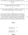
Figure 1 is a schematic flowchart of a method for realizing intelligent constant-speed and energy-saving driving according to an embodiment of the present application; -
Figure 2 is another schematic flowchart of the method for realizing intelligent constant-speed and energy-saving driving according to an embodiment of the present application; and -
Figure 3 is a schematic structural diagram of a device for realizing intelligent constant-speed and energy-saving driving according to an embodiment of the present application. - The technical solutions according to the embodiments of the present application will be described clearly and completely as follows in conjunction with the drawings in the embodiments of the present application. It is apparent that the described embodiments are only a part of the embodiments according to the present application, rather than all the embodiments. Based on the embodiments of the present application, all other embodiments, made by those skilled in the art without any creative efforts, fall into the scope of the present application.
- Referring to
Figure 1, Figure 1 is a schematic flowchart of a method for realizing intelligent constant-speed and energy-saving driving according to an embodiment of the present application, the method is applied to a central control unit, and the method includes: - Step S101, obtaining control information of a train when the train enters an intelligent constant-speed mode.
- The control information includes route information and train information.
- In practical applications, the control information may be information of timetables, running maps, train speed, ramps, curves, stations, roads, bridges, tunnels, speed limit, train length, unit mass, load, auxiliary power, traction\braking force characteristics, resistance characteristics, and so on.
- Preferably, before step S101, the method further includes:
- determining whether the train meets a condition for entering the intelligent constant-speed mode;
- determining whether an instruction of entering the intelligent constant-speed mode is received, if the condition for entering the intelligent constant-speed mode is met; and
- performing the obtaining control information of the train, if the instruction of entering the intelligent constant-speed mode is received.
- In the embodiments of the present application, if the train meets the condition for entering the intelligent constant-speed mode, the driver may trigger a specific button to enter the mode.
- Step S102, generating an automatic driving and energy-saving control strategy according to the control information on the basis of meeting a running time of normal operation of the train, and controlling operation of the train according to the automatic driving and energy-saving control strategy.
- The step of generating an automatic driving and energy-saving control strategy according to the control information on the basis of meeting a running time of normal operation of the train includes:
- generating a first automatic driving and energy-saving control strategy, if the route information indicates that the train is running on a gentle route, wherein the first automatic driving and energy-saving control strategy is to control the speed of the train to rise from a given speed to a first speed by using maximum-power traction at a starting portion of the route, and to reduce the speed of the train from the first speed to a second speed through an idle running condition in remainder of the route, and to reduce the speed of the train from the second speed to zero by braking deceleration, wherein the first speed is less than a speed limit threshold, and the given speed is a speed when the train enters the intelligent constant-speed mode; and
- generating a second automatic driving and energy-saving control strategy, if the route information indicates that the train is running on a complex route, wherein the complex route includes an uphill route and/or a downhill route, and in a case that the complex route includes the uphill route, the second automatic driving and energy-saving control strategy is to start speeding up the train by using the maximum-power traction within a preset distance before the train enters the uphill route; and in a case that the complex route includes the downhill route, the second automatic driving and energy-saving control strategy is to control the speed of the train to drop by using the idle running condition within a preset distance before the train enters the downhill route.
- In the present embodiment, the CCU controls the train to enter the intelligent constant-speed mode. If the forward route is uphill, the train is accelerated in advance by the maximum-power traction, or if the forward route is downhill, the train is decelerated in advance by the idle running condition. Since the train is decelerated before going downhill, the potential energy of the train when going downhill is converted into the kinetic energy of the train, so that the train is speeded up on the basis of the first speed, thereby reducing the energy consumption of the train while ensuring the running time of the train. In addition, speeding up the train in advance on the basis of the given speed before going uphill also reduces the energy consumption of the train, compared with speeding up the train after going uphill. Finally, if the train is running on a gentle route, the train is accelerated only at the starting portion of the route, and then is driven by the idle running condition until the train is decelerated at a tail end of the route, which reduces the energy consumption of the train, compared with that the train keeps travelling at a constant speed in the conventional technology.
- In another embodiment of the present application, the speed of the train is reduced from the second speed to zero by braking deceleration. Specifically, the speed of the train may be decelerated from the second speed to zero by means of electric braking. The electric braking can convert the kinetic energy of the train into electric energy, so that the electric braking can also reduce the energy consumption of the train, compared with air braking.
- In another embodiment of the present application, the controlling the speed of the train to rise from a given speed to a first speed by using maximum-power traction at a starting portion of the route, as show in
Figure 2 , includes: - Step S201, planning a speed-time curve of the train according to the control information;
- Step S102, calculating resistance of the gentle route in real time to obtain a calculation result of the route resistance;
- Step S203, calculating a real-time output power according to the speed-time curve and the calculation result of the route resistance;
- Step S204, performing a matching calculation for power units according to the real-time output power to obtain a calculation result of power-matching; and
- Step S205, obtaining a power-switching instruction based on the calculation result of power-matching to control the power units to be turned on or off according to the calculation result of power-matching, wherein activation or shutdown of the power units allows the speed of the train to rise from the given speed to the first speed.
- In another embodiment of the present application, the step of generating an automatic driving and energy-saving control strategy according to the control information on the basis of meeting a running time of normal operation of the train may include:
- using maximum-power traction to ensure that the train is accelerated quickly, if the speed of the train needs to rise; and
- using the idle running condition, if the speed of the train needs to decrease; or using maximum-power braking, if the idle running condition cannot meet deceleration requirements of the train.
- According to the technical solutions provided by the embodiments of the present application, when the train enters the intelligent constant-speed operation mode, the control information of the trains is obtained, and an automatic driving and energy-saving control strategy according to the control information on the basis of meeting a running time of normal operation of the train is generated, thereby controlling operation of the train according to the automatic driving and energy-saving control strategy. Since the automatic driving and energy-saving control strategy is generated according to the route information, the embodiments of the present application can reduce the energy consumption of the train, compared with the constant-speed operation in the conventional technology.
- Referring to
Figure 3, Figure 3 is a schematic structural diagram of a device for realizing intelligent constant-speed and energy-saving driving according to an embodiment of the present application. Working process of each module in the schematic structural diagram refers to the execution process of the method in the embodiment corresponding toFigure 1 . The device includes: - an obtaining
unit 310, configured to obtain control information of a train when the train enters an intelligent constant-speed operation mode, wherein the control information includes route information and train information; and - a
processing unit 320, configured to generate an automatic driving and energy-saving control strategy according to the control information on the basis of meeting a running time of normal operation of the train, and to control operation of the train according to the automatic driving and energy-saving control strategy. - According to the technical solutions provided by the embodiments of the present application, when the train enters the intelligent constant-speed operation mode, the control information of the trains is obtained, and an automatic driving and energy-saving control strategy according to the control information on the basis of meeting a running time of normal operation of the train is generated, thereby controlling operation of the train according to the automatic driving and energy-saving control strategy. Since the automatic driving and energy-saving control strategy is generated according to the route information, the embodiments of the present application can reduce the energy consumption of the train, compared with the constant-speed operation in the conventional technology.
- In another embodiment of the present application, it is preferred that the processing unit is specifically configured to:
- generate a first automatic driving and energy-saving control strategy, if the route information indicates that the train is running on a gentle route, wherein the first automatic driving and energy-saving control strategy is to control the speed of the train to rise from a given speed to a first speed by using maximum-power traction at a starting portion of the route, and to reduce the speed of the train from the first speed to a second speed through an idle running condition in remainder of the route, and to reduce the speed of the train from the second speed to zero by braking deceleration, wherein the first speed is less than a speed limit threshold, and the given speed is a speed when the train enters the intelligent constant-speed mode; and
- generate a second automatic driving and energy-saving control strategy, if the route information indicates that the train is running on a complex route, wherein the complex route includes an uphill route and/or a downhill route, and in a case that the complex route includes the uphill route, the second automatic driving and energy-saving control strategy is to start speeding up the train by using the maximum-power traction within a preset distance before the train enters the uphill route; and in a case that the complex route includes the downhill route, the second automatic driving and energy-saving control strategy is to control the speed of the train to drop by using the idle running condition within a preset distance before the train enters the downhill route.
- In another embodiment of the present application, it is preferred that the reducing the speed of the train from the second speed to zero by braking deceleration in the processing unit includes:
reducing the speed of the train from the second speed to zero by means of electric braking. - In another embodiment of the present application, it is preferred that the processing unit is specifically configured to:
- plan a speed-time curve of the train according to the control information;
- calculate resistance of the gentle route in real time to obtain a calculation result of the route resistance;
- calculate a real-time output power according to the speed-time curve and the calculation result of the route resistance;
- perform a matching calculation for power units according to the real-time output power to obtain a calculation result of power-matching; and
- obtain a power-switching instruction based on the calculation result of power-matching to control the power units to be turned on or off according to the calculation result of power-matching, wherein activation or shutdown of the power units allows the speed of the train to rise from the given speed to the first speed.
- In another embodiment of the present application, it is preferred that the device further includes:
- a first determining unit, configured to determine whether the train meets a condition for entering the intelligent constant-speed mode; and
- a second determining unit, configured to determine whether an instruction of entering the intelligent constant-speed mode is received, if the condition for entering the intelligent constant-speed mode is met, wherein the obtaining control information of the train in the obtaining unit is performed, if the instruction of entering the intelligent constant-speed mode is received.
- In the specification, claims, and accompanying drawings of the present application, the terms "first", "second", "third", "fourth", and the like (if existing) are intended to distinguish between similar objects rather than describe a specific order. It should be understood that, data used in this way can be interchanged in an appropriate case, so that the embodiments of the present application that are described herein, for example, can be implemented in a sequence other than those sequences illustrated or described herein. In addition, the terms "include" and "have" and any variations thereof are intended to cover non-exclusive inclusions. For example, a process, a method, a system, a product or a device that includes a series of steps or units is not limited to those clearly listed steps or units, and may instead include other steps or units not explicitly listed or inherent to the process, method, product or device.
- Since the device or system embodiment corresponds to the method embodiment, reference may be made to the method embodiment for the relevant parts. The device or system embodiment described above is merely illustrative. The units described as separate components may be or not be separated physically. The components shown as units may be or not be physical units, i.e., the units may be located at a same place or may be distributed onto multiple network units. A part or all of the modules may be selected based on actual needs to implement the solution according to the embodiment. Those skilled in the art may understand and implement the present application without creative work.
- In the embodiments according to the present application, it should be understood that the disclosed system, device and method may be implemented in other ways without departing from the spirit and scope of the present application. The present embodiments are only exemplary examples and should not be construed as a limitation, and the specific contents given should not limit the purpose of the present application. For example, the units or sub-units are merely divided according to a logic function, and the units may be divided in other way in practice. For example, multiple units or sub-units may be combined. Moreover, the units are or parts may be combined or integrated into another system, or some features may be omitted or not performed.
- In addition, the described system, device, and method, as well as schematic diagrams of different embodiments, can be combined or integrated with other systems, modules, technologies, or methods without departing from the scope of the present application. In addition, the coupling, direct coupling or communication connection between components which are shown or discussed may be indirect coupling or communication connection via some interfaces, devices or units, which may be electrical, mechanical, or in other form.
- Only specific embodiments of the present application are described above, it should be pointed out that various improvements and modifications can be made by those skilled in the art without departing from the principle of the present application, and these improvements and modifications should fall within the protection scope of the present application.
Claims (10)
- A method for realizing intelligent constant-speed and energy-saving driving, wherein the method is applied to a central control unit, and comprises:obtaining control information of a train when the train enters an intelligent constant-speed mode, wherein the control information comprises route information and train information; andgenerating an automatic driving and energy-saving control strategy according to the control information while meeting a running time of normal operation of the train, and controlling operation of the train according to the automatic driving and energy-saving control strategy.
- The method according to claim 1, wherein the generating an automatic driving and energy-saving control strategy according to the control information while meeting a running time of normal operation of the train comprises:generating a first automatic driving and energy-saving control strategy, if the route information indicates that the train is running on a gentle route, wherein the first automatic driving and energy-saving control strategy is to control a speed of the train to rise from a given speed to a first speed by using maximum-power traction at a starting portion of the route, and to reduce the speed of the train from the first speed to a second speed through an idle running condition in remainder of the route, and to reduce the speed of the train from the second speed to zero by braking deceleration, wherein the first speed is less than a speed limit threshold, and the given speed is a speed when the train enters the intelligent constant-speed mode; andgenerating a second automatic driving and energy-saving control strategy, if the route information indicates that the train is running on a complex route, wherein the complex route comprises an uphill route and/or a downhill route, and in a case that the complex route comprises the uphill route, the second automatic driving and energy-saving control strategy is to start speeding up the train by using the maximum-power traction within a preset distance before the train enters the uphill route; and in a case that the complex route comprises the downhill route, the second automatic driving and energy-saving control strategy is to control the speed of the train to drop by using the idle running condition within a preset distance before the train enters the downhill route.
- The method according to claim 2, wherein the reducing the speed of the train from the second speed to zero by braking deceleration comprises:
reducing the speed of the train from the second speed to zero by means of electric braking. - The method according to claim 2, wherein the controlling the speed of the train to rise from a given speed to a first speed by using maximum-power traction at a starting portion of the route comprises:planning a speed-time curve of the train according to the control information;calculating resistance of the gentle route in real time to obtain a calculation result of the route resistance;calculating a real-time output power according to the speed-time curve and the calculation result of the route resistance;performing a matching calculation for power units according to the real-time output power to obtain a calculation result of power-matching; andobtaining a power-switching instruction based on the calculation result of power-matching to control the power units to be turned on or off according to the calculation result of power-matching, wherein activation or shutdown of the power units allows the speed of the train to rise from the given speed to the first speed.
- The method according to claim 1, further comprising:determining whether the train meets a condition for entering the intelligent constant-speed mode;determining whether an instruction of entering the intelligent constant-speed mode is received, if the condition for entering the intelligent constant-speed mode is met; andperforming the obtaining control information of the train, if the instruction of entering the intelligent constant-speed mode is received.
- A device for realizing intelligent constant-speed and energy-saving driving, wherein the device is applied to a central control unit, and comprises:an obtaining unit, configured to obtain control information of a train when the train enters an intelligent constant-speed mode, wherein the control information comprises route information and train information; anda processing unit, configured to generate an automatic driving and energy-saving control strategy according to the control information on the basis of meeting a running time of normal operation of the train, and to control operation of the train according to the automatic driving and energy-saving control strategy.
- The device according to claim 6, wherein the processing unit is configured to:generate a first automatic driving and energy-saving control strategy, if the route information indicates that the train is running on a gentle route, wherein the first automatic driving and energy-saving control strategy is to control a speed of the train to rise from a given speed to a first speed by using maximum-power traction at a starting portion of the route, and to reduce the speed of the train from the first speed to a second speed through an idle running condition in remainder of the route, and to reduce the speed of the train from the second speed to zero by braking deceleration, wherein the first speed is less than a speed limit threshold, and the given speed is a speed when the train enters the intelligent constant-speed mode; andgenerate a second automatic driving and energy-saving control strategy, if the route information indicates that the train is running on a complex route, wherein the complex route comprises an uphill route and/or a downhill route, and in a case that the complex route comprises the uphill route, the second automatic driving and energy-saving control strategy is to start speeding up the train by using the maximum-power traction within a preset distance before the train enters the uphill route; and in a case that the complex route comprises the downhill route, the second automatic driving and energy-saving control strategy is to control the speed of the train to drop by using the idle running condition within a preset distance before the train enters the downhill route.
- The device according to claim 7, wherein the reducing the speed of the train from the second speed to zero by braking deceleration in the processing unit comprises:
reducing the speed of the train from the second speed to zero by means of electric braking. - The device according to claim 7, wherein the processing unit is configured to:plan a speed-time curve of the train according to the control information;calculate resistance of the gentle route in real time to obtain a calculation result of the route resistance;calculate a real-time output power according to the speed-time curve and the calculation result of the route resistance;perform a matching calculation for power units according to the real-time output power to obtain a calculation result of power-matching; andobtain a power-switching instruction based on the calculation result of power-matching to control the power units to be turned on or off according to the calculation result of power-matching, wherein activation or shutdown of the power units allows the speed of the train to rise from the given speed to the first speed.
- The device according to claim 6, further comprising:a first determining unit, configured to determine whether the train meets a condition for entering the intelligent constant-speed mode; anda second determining unit, configured to determine whether an instruction of entering the intelligent constant-speed mode is received, if the condition for entering the intelligent constant-speed mode is met, wherein the obtaining control information of the train in the obtaining unit is performed, if the instruction of entering the intelligent constant-speed mode is received.
Applications Claiming Priority (2)
| Application Number | Priority Date | Filing Date | Title |
|---|---|---|---|
| CN201811440774.0A CN109591861B (en) | 2018-11-29 | 2018-11-29 | Method and device for realizing intelligent constant speed and energy-saving driving |
| PCT/CN2018/120147 WO2020107526A1 (en) | 2018-11-29 | 2018-12-10 | Method and device capable of achieving intelligent constant speed and energy-saving driving |
Publications (3)
| Publication Number | Publication Date |
|---|---|
| EP3686082A1 true EP3686082A1 (en) | 2020-07-29 |
| EP3686082A4 EP3686082A4 (en) | 2020-12-16 |
| EP3686082B1 EP3686082B1 (en) | 2024-02-28 |
Family
ID=65959894
Family Applications (1)
| Application Number | Title | Priority Date | Filing Date |
|---|---|---|---|
| EP18921295.4A Active EP3686082B1 (en) | 2018-11-29 | 2018-12-10 | Method and device capable of achieving intelligent constant speed and energy-saving driving |
Country Status (5)
| Country | Link |
|---|---|
| EP (1) | EP3686082B1 (en) |
| CN (1) | CN109591861B (en) |
| MY (1) | MY202091A (en) |
| SG (1) | SG11201911938XA (en) |
| WO (1) | WO2020107526A1 (en) |
Cited By (1)
| Publication number | Priority date | Publication date | Assignee | Title |
|---|---|---|---|---|
| US12552425B2 (en) | 2023-10-31 | 2026-02-17 | Progress Rail Locomotive Inc. | Systems and methods for deploying locomotives within a consist |
Families Citing this family (9)
| Publication number | Priority date | Publication date | Assignee | Title |
|---|---|---|---|---|
| CN111016969B (en) * | 2019-12-12 | 2021-11-30 | 广州地铁集团有限公司 | Method and device for controlling vehicle intervention type coasting |
| CN111232019A (en) * | 2020-01-14 | 2020-06-05 | 中车株洲电力机车有限公司 | Traction brake distribution method, device, system, medium and railway vehicle |
| CN111216722A (en) * | 2020-02-27 | 2020-06-02 | 北京四维智联科技有限公司 | Vehicle driving control method, device, equipment and storage medium |
| CN112297875B (en) * | 2020-10-27 | 2022-04-15 | 中车青岛四方机车车辆股份有限公司 | Control method and control system for constant-speed running of rail transit vehicle and vehicle |
| CN112660202B (en) * | 2021-01-04 | 2022-05-10 | 中车青岛四方车辆研究所有限公司 | Train automatic driving system integrated with vehicle depth |
| CN113147841A (en) * | 2021-05-13 | 2021-07-23 | 中车长春轨道客车股份有限公司 | Rail vehicle capacity management and energy-saving auxiliary driving method and related device |
| CN113264060B (en) * | 2021-05-28 | 2023-03-21 | 东风汽车集团股份有限公司 | Automatic driving energy-saving system and method based on cloud training model |
| CN116118792A (en) * | 2021-11-15 | 2023-05-16 | 中移(上海)信息通信科技有限公司 | Control method and device for rail electric locomotive and electronic equipment |
| CN115610458B (en) * | 2022-10-31 | 2025-06-13 | 中车长春轨道客车股份有限公司 | Power control method and device |
Family Cites Families (10)
| Publication number | Priority date | Publication date | Assignee | Title |
|---|---|---|---|---|
| JP4518820B2 (en) * | 2004-03-18 | 2010-08-04 | 三菱電機株式会社 | High-speed driving support device |
| CN103963805A (en) * | 2014-04-25 | 2014-08-06 | 北京交通大学 | Energy-saving method of train operation of urban mass transit |
| CN104787091B (en) * | 2015-04-28 | 2016-08-03 | 北京交通大学 | A kind of train automatic Pilot control car effect monitoring system |
| CN105243430B (en) * | 2015-09-07 | 2018-10-09 | 北京交通大学 | The optimization method of the target velocity curve of energy-saving train operation |
| MX2018011798A (en) * | 2016-04-19 | 2019-01-21 | New York Air Brake Llc | Speed profiling for locomotive display and event recorder. |
| CN105835914B (en) * | 2016-05-19 | 2018-02-23 | 北京交通大学 | Remove the energy-saving train operation control method of unnecessary traction |
| CN106494468B (en) * | 2016-10-19 | 2018-04-20 | 北京交通大学 | A kind of operation control method for train and system |
| JP2018184135A (en) * | 2017-04-27 | 2018-11-22 | 株式会社東芝 | Operation curve creation device |
| CN107972698B (en) * | 2017-11-22 | 2019-08-06 | 清华大学 | A kind of train ATO hypervelocity safe precaution method |
| CN108791367B (en) * | 2018-06-01 | 2020-09-15 | 广州地铁设计研究院有限公司 | Energy-saving operation method of train |
-
2018
- 2018-11-29 CN CN201811440774.0A patent/CN109591861B/en active Active
- 2018-12-10 MY MYPI2019007392A patent/MY202091A/en unknown
- 2018-12-10 WO PCT/CN2018/120147 patent/WO2020107526A1/en not_active Ceased
- 2018-12-10 EP EP18921295.4A patent/EP3686082B1/en active Active
- 2018-12-10 SG SG11201911938XA patent/SG11201911938XA/en unknown
Cited By (1)
| Publication number | Priority date | Publication date | Assignee | Title |
|---|---|---|---|---|
| US12552425B2 (en) | 2023-10-31 | 2026-02-17 | Progress Rail Locomotive Inc. | Systems and methods for deploying locomotives within a consist |
Also Published As
| Publication number | Publication date |
|---|---|
| CN109591861B (en) | 2020-05-29 |
| CN109591861A (en) | 2019-04-09 |
| MY202091A (en) | 2024-04-03 |
| SG11201911938XA (en) | 2020-07-29 |
| WO2020107526A1 (en) | 2020-06-04 |
| EP3686082A4 (en) | 2020-12-16 |
| EP3686082B1 (en) | 2024-02-28 |
Similar Documents
| Publication | Publication Date | Title |
|---|---|---|
| EP3686082B1 (en) | Method and device capable of achieving intelligent constant speed and energy-saving driving | |
| US11285935B2 (en) | Driving support apparatus | |
| CN105551276B (en) | Road traffic speed abductive approach | |
| US9140565B2 (en) | Travel plan generation method and travel plan generation device | |
| EP2980389B1 (en) | Travel controlling device and travel controlling system | |
| US10239526B2 (en) | Adaptive cruise control system | |
| US9718473B2 (en) | Travel control device and travel control method | |
| CN110047271B (en) | Motorcade management system and motorcade management method based on same | |
| KR102518656B1 (en) | Method for Inertia Drive Control with Torque Sharing of Eco Friendly Vehicle | |
| CN107067753B (en) | A car-following automatic driving method based on driving safety distance | |
| WO2018233265A1 (en) | Vehicle control method and system | |
| US20160144861A1 (en) | Driving assistance apparatus | |
| WO2015098521A1 (en) | Driving curve creation device, driving assistance device, driving control device, and driving curve creation method | |
| EP2650186A2 (en) | Drive system and control method of train | |
| CN114162178B (en) | Virtual marshalling train control method, equipment and storage medium based on time reference | |
| US11322023B2 (en) | Driving support apparatus | |
| CN108682168A (en) | A kind of speed guiding system and method reducing signal intersection parking | |
| JP2020097337A (en) | Driving assistance apparatus | |
| JP2023109355A (en) | Vehicle driving support device | |
| CN110435629A (en) | Method of adjustment, device, system and the vehicle of running speed | |
| CN114274956A (en) | Vehicle cruise control method and device, vehicle and readable storage medium | |
| JPH10320691A (en) | Self-driving vehicle | |
| CN110525431B (en) | Special vehicle anti-collision method applied to airport based on intelligent control | |
| CN113990063A (en) | Intersection tramcar signal priority control method based on dual-network fusion | |
| WO2023082309A1 (en) | Train control method and apparatus, electronic device, and storage medium |
Legal Events
| Date | Code | Title | Description |
|---|---|---|---|
| STAA | Information on the status of an ep patent application or granted ep patent |
Free format text: STATUS: UNKNOWN |
|
| STAA | Information on the status of an ep patent application or granted ep patent |
Free format text: STATUS: THE INTERNATIONAL PUBLICATION HAS BEEN MADE |
|
| PUAI | Public reference made under article 153(3) epc to a published international application that has entered the european phase |
Free format text: ORIGINAL CODE: 0009012 |
|
| STAA | Information on the status of an ep patent application or granted ep patent |
Free format text: STATUS: REQUEST FOR EXAMINATION WAS MADE |
|
| 17P | Request for examination filed |
Effective date: 20191211 |
|
| AK | Designated contracting states |
Kind code of ref document: A1 Designated state(s): AL AT BE BG CH CY CZ DE DK EE ES FI FR GB GR HR HU IE IS IT LI LT LU LV MC MK MT NL NO PL PT RO RS SE SI SK SM TR |
|
| AX | Request for extension of the european patent |
Extension state: BA ME |
|
| A4 | Supplementary search report drawn up and despatched |
Effective date: 20201117 |
|
| RIC1 | Information provided on ipc code assigned before grant |
Ipc: B61L 27/04 20060101AFI20201111BHEP Ipc: B61L 27/00 20060101ALI20201111BHEP Ipc: B61L 23/00 20060101ALI20201111BHEP Ipc: B61L 25/02 20060101ALI20201111BHEP Ipc: B60W 30/14 20060101ALI20201111BHEP |
|
| DAV | Request for validation of the european patent (deleted) | ||
| DAX | Request for extension of the european patent (deleted) | ||
| GRAP | Despatch of communication of intention to grant a patent |
Free format text: ORIGINAL CODE: EPIDOSNIGR1 |
|
| STAA | Information on the status of an ep patent application or granted ep patent |
Free format text: STATUS: GRANT OF PATENT IS INTENDED |
|
| RIC1 | Information provided on ipc code assigned before grant |
Ipc: B61L 27/00 20060101ALI20230914BHEP Ipc: B60W 30/14 20060101ALI20230914BHEP Ipc: B61L 23/00 20060101ALI20230914BHEP Ipc: B61L 25/02 20060101ALI20230914BHEP Ipc: B61L 27/04 20060101AFI20230914BHEP |
|
| INTG | Intention to grant announced |
Effective date: 20231013 |
|
| GRAS | Grant fee paid |
Free format text: ORIGINAL CODE: EPIDOSNIGR3 |
|
| GRAA | (expected) grant |
Free format text: ORIGINAL CODE: 0009210 |
|
| STAA | Information on the status of an ep patent application or granted ep patent |
Free format text: STATUS: THE PATENT HAS BEEN GRANTED |
|
| AK | Designated contracting states |
Kind code of ref document: B1 Designated state(s): AL AT BE BG CH CY CZ DE DK EE ES FI FR GB GR HR HU IE IS IT LI LT LU LV MC MK MT NL NO PL PT RO RS SE SI SK SM TR |
|
| REG | Reference to a national code |
Ref country code: GB Ref legal event code: FG4D |
|
| REG | Reference to a national code |
Ref country code: CH Ref legal event code: EP |
|
| REG | Reference to a national code |
Ref country code: DE Ref legal event code: R096 Ref document number: 602018066052 Country of ref document: DE |
|
| REG | Reference to a national code |
Ref country code: IE Ref legal event code: FG4D |
|
| REG | Reference to a national code |
Ref country code: LT Ref legal event code: MG9D |
|
| PG25 | Lapsed in a contracting state [announced via postgrant information from national office to epo] |
Ref country code: IS Free format text: LAPSE BECAUSE OF FAILURE TO SUBMIT A TRANSLATION OF THE DESCRIPTION OR TO PAY THE FEE WITHIN THE PRESCRIBED TIME-LIMIT Effective date: 20240628 |
|
| REG | Reference to a national code |
Ref country code: NL Ref legal event code: MP Effective date: 20240228 |
|
| PG25 | Lapsed in a contracting state [announced via postgrant information from national office to epo] |
Ref country code: LT Free format text: LAPSE BECAUSE OF FAILURE TO SUBMIT A TRANSLATION OF THE DESCRIPTION OR TO PAY THE FEE WITHIN THE PRESCRIBED TIME-LIMIT Effective date: 20240228 |
|
| PG25 | Lapsed in a contracting state [announced via postgrant information from national office to epo] |
Ref country code: GR Free format text: LAPSE BECAUSE OF FAILURE TO SUBMIT A TRANSLATION OF THE DESCRIPTION OR TO PAY THE FEE WITHIN THE PRESCRIBED TIME-LIMIT Effective date: 20240529 |
|
| PG25 | Lapsed in a contracting state [announced via postgrant information from national office to epo] |
Ref country code: HR Free format text: LAPSE BECAUSE OF FAILURE TO SUBMIT A TRANSLATION OF THE DESCRIPTION OR TO PAY THE FEE WITHIN THE PRESCRIBED TIME-LIMIT Effective date: 20240228 Ref country code: RS Free format text: LAPSE BECAUSE OF FAILURE TO SUBMIT A TRANSLATION OF THE DESCRIPTION OR TO PAY THE FEE WITHIN THE PRESCRIBED TIME-LIMIT Effective date: 20240528 Ref country code: NL Free format text: LAPSE BECAUSE OF FAILURE TO SUBMIT A TRANSLATION OF THE DESCRIPTION OR TO PAY THE FEE WITHIN THE PRESCRIBED TIME-LIMIT Effective date: 20240228 |
|
| PG25 | Lapsed in a contracting state [announced via postgrant information from national office to epo] |
Ref country code: ES Free format text: LAPSE BECAUSE OF FAILURE TO SUBMIT A TRANSLATION OF THE DESCRIPTION OR TO PAY THE FEE WITHIN THE PRESCRIBED TIME-LIMIT Effective date: 20240228 |
|
| PG25 | Lapsed in a contracting state [announced via postgrant information from national office to epo] |
Ref country code: RS Free format text: LAPSE BECAUSE OF FAILURE TO SUBMIT A TRANSLATION OF THE DESCRIPTION OR TO PAY THE FEE WITHIN THE PRESCRIBED TIME-LIMIT Effective date: 20240528 Ref country code: NO Free format text: LAPSE BECAUSE OF FAILURE TO SUBMIT A TRANSLATION OF THE DESCRIPTION OR TO PAY THE FEE WITHIN THE PRESCRIBED TIME-LIMIT Effective date: 20240528 Ref country code: NL Free format text: LAPSE BECAUSE OF FAILURE TO SUBMIT A TRANSLATION OF THE DESCRIPTION OR TO PAY THE FEE WITHIN THE PRESCRIBED TIME-LIMIT Effective date: 20240228 Ref country code: LT Free format text: LAPSE BECAUSE OF FAILURE TO SUBMIT A TRANSLATION OF THE DESCRIPTION OR TO PAY THE FEE WITHIN THE PRESCRIBED TIME-LIMIT Effective date: 20240228 Ref country code: IS Free format text: LAPSE BECAUSE OF FAILURE TO SUBMIT A TRANSLATION OF THE DESCRIPTION OR TO PAY THE FEE WITHIN THE PRESCRIBED TIME-LIMIT Effective date: 20240628 Ref country code: HR Free format text: LAPSE BECAUSE OF FAILURE TO SUBMIT A TRANSLATION OF THE DESCRIPTION OR TO PAY THE FEE WITHIN THE PRESCRIBED TIME-LIMIT Effective date: 20240228 Ref country code: GR Free format text: LAPSE BECAUSE OF FAILURE TO SUBMIT A TRANSLATION OF THE DESCRIPTION OR TO PAY THE FEE WITHIN THE PRESCRIBED TIME-LIMIT Effective date: 20240529 Ref country code: FI Free format text: LAPSE BECAUSE OF FAILURE TO SUBMIT A TRANSLATION OF THE DESCRIPTION OR TO PAY THE FEE WITHIN THE PRESCRIBED TIME-LIMIT Effective date: 20240228 Ref country code: ES Free format text: LAPSE BECAUSE OF FAILURE TO SUBMIT A TRANSLATION OF THE DESCRIPTION OR TO PAY THE FEE WITHIN THE PRESCRIBED TIME-LIMIT Effective date: 20240228 Ref country code: BG Free format text: LAPSE BECAUSE OF FAILURE TO SUBMIT A TRANSLATION OF THE DESCRIPTION OR TO PAY THE FEE WITHIN THE PRESCRIBED TIME-LIMIT Effective date: 20240228 |
|
| PG25 | Lapsed in a contracting state [announced via postgrant information from national office to epo] |
Ref country code: PL Free format text: LAPSE BECAUSE OF FAILURE TO SUBMIT A TRANSLATION OF THE DESCRIPTION OR TO PAY THE FEE WITHIN THE PRESCRIBED TIME-LIMIT Effective date: 20240228 Ref country code: PT Free format text: LAPSE BECAUSE OF FAILURE TO SUBMIT A TRANSLATION OF THE DESCRIPTION OR TO PAY THE FEE WITHIN THE PRESCRIBED TIME-LIMIT Effective date: 20240628 |
|
| REG | Reference to a national code |
Ref country code: AT Ref legal event code: MK05 Ref document number: 1660993 Country of ref document: AT Kind code of ref document: T Effective date: 20240228 |
|
| PG25 | Lapsed in a contracting state [announced via postgrant information from national office to epo] |
Ref country code: SE Free format text: LAPSE BECAUSE OF FAILURE TO SUBMIT A TRANSLATION OF THE DESCRIPTION OR TO PAY THE FEE WITHIN THE PRESCRIBED TIME-LIMIT Effective date: 20240228 Ref country code: PT Free format text: LAPSE BECAUSE OF FAILURE TO SUBMIT A TRANSLATION OF THE DESCRIPTION OR TO PAY THE FEE WITHIN THE PRESCRIBED TIME-LIMIT Effective date: 20240628 Ref country code: PL Free format text: LAPSE BECAUSE OF FAILURE TO SUBMIT A TRANSLATION OF THE DESCRIPTION OR TO PAY THE FEE WITHIN THE PRESCRIBED TIME-LIMIT Effective date: 20240228 Ref country code: LV Free format text: LAPSE BECAUSE OF FAILURE TO SUBMIT A TRANSLATION OF THE DESCRIPTION OR TO PAY THE FEE WITHIN THE PRESCRIBED TIME-LIMIT Effective date: 20240228 |
|
| PG25 | Lapsed in a contracting state [announced via postgrant information from national office to epo] |
Ref country code: DK Free format text: LAPSE BECAUSE OF FAILURE TO SUBMIT A TRANSLATION OF THE DESCRIPTION OR TO PAY THE FEE WITHIN THE PRESCRIBED TIME-LIMIT Effective date: 20240228 |
|
| PG25 | Lapsed in a contracting state [announced via postgrant information from national office to epo] |
Ref country code: SM Free format text: LAPSE BECAUSE OF FAILURE TO SUBMIT A TRANSLATION OF THE DESCRIPTION OR TO PAY THE FEE WITHIN THE PRESCRIBED TIME-LIMIT Effective date: 20240228 |
|
| PG25 | Lapsed in a contracting state [announced via postgrant information from national office to epo] |
Ref country code: CZ Free format text: LAPSE BECAUSE OF FAILURE TO SUBMIT A TRANSLATION OF THE DESCRIPTION OR TO PAY THE FEE WITHIN THE PRESCRIBED TIME-LIMIT Effective date: 20240228 Ref country code: EE Free format text: LAPSE BECAUSE OF FAILURE TO SUBMIT A TRANSLATION OF THE DESCRIPTION OR TO PAY THE FEE WITHIN THE PRESCRIBED TIME-LIMIT Effective date: 20240228 |
|
| PG25 | Lapsed in a contracting state [announced via postgrant information from national office to epo] |
Ref country code: AT Free format text: LAPSE BECAUSE OF FAILURE TO SUBMIT A TRANSLATION OF THE DESCRIPTION OR TO PAY THE FEE WITHIN THE PRESCRIBED TIME-LIMIT Effective date: 20240228 |
|
| PG25 | Lapsed in a contracting state [announced via postgrant information from national office to epo] |
Ref country code: SK Free format text: LAPSE BECAUSE OF FAILURE TO SUBMIT A TRANSLATION OF THE DESCRIPTION OR TO PAY THE FEE WITHIN THE PRESCRIBED TIME-LIMIT Effective date: 20240228 |
|
| PG25 | Lapsed in a contracting state [announced via postgrant information from national office to epo] |
Ref country code: SM Free format text: LAPSE BECAUSE OF FAILURE TO SUBMIT A TRANSLATION OF THE DESCRIPTION OR TO PAY THE FEE WITHIN THE PRESCRIBED TIME-LIMIT Effective date: 20240228 Ref country code: SK Free format text: LAPSE BECAUSE OF FAILURE TO SUBMIT A TRANSLATION OF THE DESCRIPTION OR TO PAY THE FEE WITHIN THE PRESCRIBED TIME-LIMIT Effective date: 20240228 Ref country code: RO Free format text: LAPSE BECAUSE OF FAILURE TO SUBMIT A TRANSLATION OF THE DESCRIPTION OR TO PAY THE FEE WITHIN THE PRESCRIBED TIME-LIMIT Effective date: 20240228 Ref country code: EE Free format text: LAPSE BECAUSE OF FAILURE TO SUBMIT A TRANSLATION OF THE DESCRIPTION OR TO PAY THE FEE WITHIN THE PRESCRIBED TIME-LIMIT Effective date: 20240228 Ref country code: DK Free format text: LAPSE BECAUSE OF FAILURE TO SUBMIT A TRANSLATION OF THE DESCRIPTION OR TO PAY THE FEE WITHIN THE PRESCRIBED TIME-LIMIT Effective date: 20240228 Ref country code: CZ Free format text: LAPSE BECAUSE OF FAILURE TO SUBMIT A TRANSLATION OF THE DESCRIPTION OR TO PAY THE FEE WITHIN THE PRESCRIBED TIME-LIMIT Effective date: 20240228 Ref country code: AT Free format text: LAPSE BECAUSE OF FAILURE TO SUBMIT A TRANSLATION OF THE DESCRIPTION OR TO PAY THE FEE WITHIN THE PRESCRIBED TIME-LIMIT Effective date: 20240228 |
|
| REG | Reference to a national code |
Ref country code: DE Ref legal event code: R097 Ref document number: 602018066052 Country of ref document: DE |
|
| PG25 | Lapsed in a contracting state [announced via postgrant information from national office to epo] |
Ref country code: IT Free format text: LAPSE BECAUSE OF FAILURE TO SUBMIT A TRANSLATION OF THE DESCRIPTION OR TO PAY THE FEE WITHIN THE PRESCRIBED TIME-LIMIT Effective date: 20240228 |
|
| PG25 | Lapsed in a contracting state [announced via postgrant information from national office to epo] |
Ref country code: IT Free format text: LAPSE BECAUSE OF FAILURE TO SUBMIT A TRANSLATION OF THE DESCRIPTION OR TO PAY THE FEE WITHIN THE PRESCRIBED TIME-LIMIT Effective date: 20240228 |
|
| PLBE | No opposition filed within time limit |
Free format text: ORIGINAL CODE: 0009261 |
|
| STAA | Information on the status of an ep patent application or granted ep patent |
Free format text: STATUS: NO OPPOSITION FILED WITHIN TIME LIMIT |
|
| 26N | No opposition filed |
Effective date: 20241129 |
|
| PG25 | Lapsed in a contracting state [announced via postgrant information from national office to epo] |
Ref country code: SI Free format text: LAPSE BECAUSE OF FAILURE TO SUBMIT A TRANSLATION OF THE DESCRIPTION OR TO PAY THE FEE WITHIN THE PRESCRIBED TIME-LIMIT Effective date: 20240228 |
|
| REG | Reference to a national code |
Ref country code: DE Ref legal event code: R119 Ref document number: 602018066052 Country of ref document: DE |
|
| PG25 | Lapsed in a contracting state [announced via postgrant information from national office to epo] |
Ref country code: MC Free format text: LAPSE BECAUSE OF FAILURE TO SUBMIT A TRANSLATION OF THE DESCRIPTION OR TO PAY THE FEE WITHIN THE PRESCRIBED TIME-LIMIT Effective date: 20240228 |
|
| REG | Reference to a national code |
Ref country code: CH Ref legal event code: PL |
|
| PG25 | Lapsed in a contracting state [announced via postgrant information from national office to epo] |
Ref country code: LU Free format text: LAPSE BECAUSE OF NON-PAYMENT OF DUE FEES Effective date: 20241210 |
|
| GBPC | Gb: european patent ceased through non-payment of renewal fee |
Effective date: 20241210 |
|
| REG | Reference to a national code |
Ref country code: BE Ref legal event code: MM Effective date: 20241231 |
|
| PG25 | Lapsed in a contracting state [announced via postgrant information from national office to epo] |
Ref country code: DE Free format text: LAPSE BECAUSE OF NON-PAYMENT OF DUE FEES Effective date: 20250701 |
|
| PG25 | Lapsed in a contracting state [announced via postgrant information from national office to epo] |
Ref country code: GB Free format text: LAPSE BECAUSE OF NON-PAYMENT OF DUE FEES Effective date: 20241210 Ref country code: BE Free format text: LAPSE BECAUSE OF NON-PAYMENT OF DUE FEES Effective date: 20241231 |
|
| PG25 | Lapsed in a contracting state [announced via postgrant information from national office to epo] |
Ref country code: FR Free format text: LAPSE BECAUSE OF NON-PAYMENT OF DUE FEES Effective date: 20241231 |
|
| PG25 | Lapsed in a contracting state [announced via postgrant information from national office to epo] |
Ref country code: CH Free format text: LAPSE BECAUSE OF NON-PAYMENT OF DUE FEES Effective date: 20241231 |
|
| PG25 | Lapsed in a contracting state [announced via postgrant information from national office to epo] |
Ref country code: IE Free format text: LAPSE BECAUSE OF NON-PAYMENT OF DUE FEES Effective date: 20241210 |
|
| PG25 | Lapsed in a contracting state [announced via postgrant information from national office to epo] |
Ref country code: CY Free format text: LAPSE BECAUSE OF FAILURE TO SUBMIT A TRANSLATION OF THE DESCRIPTION OR TO PAY THE FEE WITHIN THE PRESCRIBED TIME-LIMIT Effective date: 20240228 |