EP3685940A1 - Recoaters with improved powder-pushing edges - Google Patents
Recoaters with improved powder-pushing edges Download PDFInfo
- Publication number
- EP3685940A1 EP3685940A1 EP19211190.4A EP19211190A EP3685940A1 EP 3685940 A1 EP3685940 A1 EP 3685940A1 EP 19211190 A EP19211190 A EP 19211190A EP 3685940 A1 EP3685940 A1 EP 3685940A1
- Authority
- EP
- European Patent Office
- Prior art keywords
- powder
- recoater
- baffle
- wall
- baffles
- Prior art date
- Legal status (The legal status is an assumption and is not a legal conclusion. Google has not performed a legal analysis and makes no representation as to the accuracy of the status listed.)
- Granted
Links
Images


Classifications
-
- B—PERFORMING OPERATIONS; TRANSPORTING
- B29—WORKING OF PLASTICS; WORKING OF SUBSTANCES IN A PLASTIC STATE IN GENERAL
- B29C—SHAPING OR JOINING OF PLASTICS; SHAPING OF MATERIAL IN A PLASTIC STATE, NOT OTHERWISE PROVIDED FOR; AFTER-TREATMENT OF THE SHAPED PRODUCTS, e.g. REPAIRING
- B29C64/00—Additive manufacturing, i.e. manufacturing of three-dimensional [3D] objects by additive deposition, additive agglomeration or additive layering, e.g. by 3D printing, stereolithography or selective laser sintering
- B29C64/10—Processes of additive manufacturing
- B29C64/141—Processes of additive manufacturing using only solid materials
- B29C64/153—Processes of additive manufacturing using only solid materials using layers of powder being selectively joined, e.g. by selective laser sintering or melting
-
- B—PERFORMING OPERATIONS; TRANSPORTING
- B05—SPRAYING OR ATOMISING IN GENERAL; APPLYING FLUENT MATERIALS TO SURFACES, IN GENERAL
- B05C—APPARATUS FOR APPLYING FLUENT MATERIALS TO SURFACES, IN GENERAL
- B05C11/00—Component parts, details or accessories not specifically provided for in groups B05C1/00 - B05C9/00
- B05C11/02—Apparatus for spreading or distributing liquids or other fluent materials already applied to a surface ; Controlling means therefor; Control of the thickness of a coating by spreading or distributing liquids or other fluent materials already applied to the coated surface
- B05C11/023—Apparatus for spreading or distributing liquids or other fluent materials already applied to a surface
-
- B—PERFORMING OPERATIONS; TRANSPORTING
- B22—CASTING; POWDER METALLURGY
- B22F—WORKING METALLIC POWDER; MANUFACTURE OF ARTICLES FROM METALLIC POWDER; MAKING METALLIC POWDER; APPARATUS OR DEVICES SPECIALLY ADAPTED FOR METALLIC POWDER
- B22F10/00—Additive manufacturing of workpieces or articles from metallic powder
- B22F10/20—Direct sintering or melting
- B22F10/28—Powder bed fusion, e.g. selective laser melting [SLM] or electron beam melting [EBM]
-
- B—PERFORMING OPERATIONS; TRANSPORTING
- B22—CASTING; POWDER METALLURGY
- B22F—WORKING METALLIC POWDER; MANUFACTURE OF ARTICLES FROM METALLIC POWDER; MAKING METALLIC POWDER; APPARATUS OR DEVICES SPECIALLY ADAPTED FOR METALLIC POWDER
- B22F10/00—Additive manufacturing of workpieces or articles from metallic powder
- B22F10/30—Process control
- B22F10/32—Process control of the atmosphere, e.g. composition or pressure in a building chamber
- B22F10/322—Process control of the atmosphere, e.g. composition or pressure in a building chamber of the gas flow, e.g. rate or direction
-
- B—PERFORMING OPERATIONS; TRANSPORTING
- B22—CASTING; POWDER METALLURGY
- B22F—WORKING METALLIC POWDER; MANUFACTURE OF ARTICLES FROM METALLIC POWDER; MAKING METALLIC POWDER; APPARATUS OR DEVICES SPECIALLY ADAPTED FOR METALLIC POWDER
- B22F12/00—Apparatus or devices specially adapted for additive manufacturing; Auxiliary means for additive manufacturing; Combinations of additive manufacturing apparatus or devices with other processing apparatus or devices
- B22F12/60—Planarisation devices; Compression devices
-
- B—PERFORMING OPERATIONS; TRANSPORTING
- B22—CASTING; POWDER METALLURGY
- B22F—WORKING METALLIC POWDER; MANUFACTURE OF ARTICLES FROM METALLIC POWDER; MAKING METALLIC POWDER; APPARATUS OR DEVICES SPECIALLY ADAPTED FOR METALLIC POWDER
- B22F12/00—Apparatus or devices specially adapted for additive manufacturing; Auxiliary means for additive manufacturing; Combinations of additive manufacturing apparatus or devices with other processing apparatus or devices
- B22F12/60—Planarisation devices; Compression devices
- B22F12/67—Blades
-
- B—PERFORMING OPERATIONS; TRANSPORTING
- B29—WORKING OF PLASTICS; WORKING OF SUBSTANCES IN A PLASTIC STATE IN GENERAL
- B29C—SHAPING OR JOINING OF PLASTICS; SHAPING OF MATERIAL IN A PLASTIC STATE, NOT OTHERWISE PROVIDED FOR; AFTER-TREATMENT OF THE SHAPED PRODUCTS, e.g. REPAIRING
- B29C64/00—Additive manufacturing, i.e. manufacturing of three-dimensional [3D] objects by additive deposition, additive agglomeration or additive layering, e.g. by 3D printing, stereolithography or selective laser sintering
- B29C64/10—Processes of additive manufacturing
- B29C64/188—Processes of additive manufacturing involving additional operations performed on the added layers, e.g. smoothing, grinding or thickness control
-
- B—PERFORMING OPERATIONS; TRANSPORTING
- B29—WORKING OF PLASTICS; WORKING OF SUBSTANCES IN A PLASTIC STATE IN GENERAL
- B29C—SHAPING OR JOINING OF PLASTICS; SHAPING OF MATERIAL IN A PLASTIC STATE, NOT OTHERWISE PROVIDED FOR; AFTER-TREATMENT OF THE SHAPED PRODUCTS, e.g. REPAIRING
- B29C64/00—Additive manufacturing, i.e. manufacturing of three-dimensional [3D] objects by additive deposition, additive agglomeration or additive layering, e.g. by 3D printing, stereolithography or selective laser sintering
- B29C64/20—Apparatus for additive manufacturing; Details thereof or accessories therefor
- B29C64/205—Means for applying layers
-
- B—PERFORMING OPERATIONS; TRANSPORTING
- B29—WORKING OF PLASTICS; WORKING OF SUBSTANCES IN A PLASTIC STATE IN GENERAL
- B29C—SHAPING OR JOINING OF PLASTICS; SHAPING OF MATERIAL IN A PLASTIC STATE, NOT OTHERWISE PROVIDED FOR; AFTER-TREATMENT OF THE SHAPED PRODUCTS, e.g. REPAIRING
- B29C64/00—Additive manufacturing, i.e. manufacturing of three-dimensional [3D] objects by additive deposition, additive agglomeration or additive layering, e.g. by 3D printing, stereolithography or selective laser sintering
- B29C64/20—Apparatus for additive manufacturing; Details thereof or accessories therefor
- B29C64/205—Means for applying layers
- B29C64/214—Doctor blades
-
- B—PERFORMING OPERATIONS; TRANSPORTING
- B29—WORKING OF PLASTICS; WORKING OF SUBSTANCES IN A PLASTIC STATE IN GENERAL
- B29C—SHAPING OR JOINING OF PLASTICS; SHAPING OF MATERIAL IN A PLASTIC STATE, NOT OTHERWISE PROVIDED FOR; AFTER-TREATMENT OF THE SHAPED PRODUCTS, e.g. REPAIRING
- B29C64/00—Additive manufacturing, i.e. manufacturing of three-dimensional [3D] objects by additive deposition, additive agglomeration or additive layering, e.g. by 3D printing, stereolithography or selective laser sintering
- B29C64/30—Auxiliary operations or equipment
- B29C64/307—Handling of material to be used in additive manufacturing
- B29C64/321—Feeding
-
- B—PERFORMING OPERATIONS; TRANSPORTING
- B29—WORKING OF PLASTICS; WORKING OF SUBSTANCES IN A PLASTIC STATE IN GENERAL
- B29C—SHAPING OR JOINING OF PLASTICS; SHAPING OF MATERIAL IN A PLASTIC STATE, NOT OTHERWISE PROVIDED FOR; AFTER-TREATMENT OF THE SHAPED PRODUCTS, e.g. REPAIRING
- B29C64/00—Additive manufacturing, i.e. manufacturing of three-dimensional [3D] objects by additive deposition, additive agglomeration or additive layering, e.g. by 3D printing, stereolithography or selective laser sintering
- B29C64/30—Auxiliary operations or equipment
- B29C64/357—Recycling
-
- B—PERFORMING OPERATIONS; TRANSPORTING
- B29—WORKING OF PLASTICS; WORKING OF SUBSTANCES IN A PLASTIC STATE IN GENERAL
- B29C—SHAPING OR JOINING OF PLASTICS; SHAPING OF MATERIAL IN A PLASTIC STATE, NOT OTHERWISE PROVIDED FOR; AFTER-TREATMENT OF THE SHAPED PRODUCTS, e.g. REPAIRING
- B29C64/00—Additive manufacturing, i.e. manufacturing of three-dimensional [3D] objects by additive deposition, additive agglomeration or additive layering, e.g. by 3D printing, stereolithography or selective laser sintering
- B29C64/30—Auxiliary operations or equipment
- B29C64/364—Conditioning of environment
- B29C64/371—Conditioning of environment using an environment other than air, e.g. inert gas
-
- B—PERFORMING OPERATIONS; TRANSPORTING
- B33—ADDITIVE MANUFACTURING TECHNOLOGY
- B33Y—ADDITIVE MANUFACTURING, i.e. MANUFACTURING OF THREE-DIMENSIONAL [3D] OBJECTS BY ADDITIVE DEPOSITION, ADDITIVE AGGLOMERATION OR ADDITIVE LAYERING, e.g. BY 3D PRINTING, STEREOLITHOGRAPHY OR SELECTIVE LASER SINTERING
- B33Y10/00—Processes of additive manufacturing
-
- B—PERFORMING OPERATIONS; TRANSPORTING
- B33—ADDITIVE MANUFACTURING TECHNOLOGY
- B33Y—ADDITIVE MANUFACTURING, i.e. MANUFACTURING OF THREE-DIMENSIONAL [3D] OBJECTS BY ADDITIVE DEPOSITION, ADDITIVE AGGLOMERATION OR ADDITIVE LAYERING, e.g. BY 3D PRINTING, STEREOLITHOGRAPHY OR SELECTIVE LASER SINTERING
- B33Y30/00—Apparatus for additive manufacturing; Details thereof or accessories therefor
-
- B—PERFORMING OPERATIONS; TRANSPORTING
- B33—ADDITIVE MANUFACTURING TECHNOLOGY
- B33Y—ADDITIVE MANUFACTURING, i.e. MANUFACTURING OF THREE-DIMENSIONAL [3D] OBJECTS BY ADDITIVE DEPOSITION, ADDITIVE AGGLOMERATION OR ADDITIVE LAYERING, e.g. BY 3D PRINTING, STEREOLITHOGRAPHY OR SELECTIVE LASER SINTERING
- B33Y40/00—Auxiliary operations or equipment, e.g. for material handling
-
- B—PERFORMING OPERATIONS; TRANSPORTING
- B22—CASTING; POWDER METALLURGY
- B22F—WORKING METALLIC POWDER; MANUFACTURE OF ARTICLES FROM METALLIC POWDER; MAKING METALLIC POWDER; APPARATUS OR DEVICES SPECIALLY ADAPTED FOR METALLIC POWDER
- B22F10/00—Additive manufacturing of workpieces or articles from metallic powder
- B22F10/30—Process control
- B22F10/32—Process control of the atmosphere, e.g. composition or pressure in a building chamber
-
- B—PERFORMING OPERATIONS; TRANSPORTING
- B22—CASTING; POWDER METALLURGY
- B22F—WORKING METALLIC POWDER; MANUFACTURE OF ARTICLES FROM METALLIC POWDER; MAKING METALLIC POWDER; APPARATUS OR DEVICES SPECIALLY ADAPTED FOR METALLIC POWDER
- B22F10/00—Additive manufacturing of workpieces or articles from metallic powder
- B22F10/30—Process control
- B22F10/37—Process control of powder bed aspects, e.g. density
-
- B—PERFORMING OPERATIONS; TRANSPORTING
- B22—CASTING; POWDER METALLURGY
- B22F—WORKING METALLIC POWDER; MANUFACTURE OF ARTICLES FROM METALLIC POWDER; MAKING METALLIC POWDER; APPARATUS OR DEVICES SPECIALLY ADAPTED FOR METALLIC POWDER
- B22F10/00—Additive manufacturing of workpieces or articles from metallic powder
- B22F10/70—Recycling
- B22F10/73—Recycling of powder
-
- B—PERFORMING OPERATIONS; TRANSPORTING
- B22—CASTING; POWDER METALLURGY
- B22F—WORKING METALLIC POWDER; MANUFACTURE OF ARTICLES FROM METALLIC POWDER; MAKING METALLIC POWDER; APPARATUS OR DEVICES SPECIALLY ADAPTED FOR METALLIC POWDER
- B22F12/00—Apparatus or devices specially adapted for additive manufacturing; Auxiliary means for additive manufacturing; Combinations of additive manufacturing apparatus or devices with other processing apparatus or devices
- B22F12/70—Gas flow means
-
- Y—GENERAL TAGGING OF NEW TECHNOLOGICAL DEVELOPMENTS; GENERAL TAGGING OF CROSS-SECTIONAL TECHNOLOGIES SPANNING OVER SEVERAL SECTIONS OF THE IPC; TECHNICAL SUBJECTS COVERED BY FORMER USPC CROSS-REFERENCE ART COLLECTIONS [XRACs] AND DIGESTS
- Y02—TECHNOLOGIES OR APPLICATIONS FOR MITIGATION OR ADAPTATION AGAINST CLIMATE CHANGE
- Y02P—CLIMATE CHANGE MITIGATION TECHNOLOGIES IN THE PRODUCTION OR PROCESSING OF GOODS
- Y02P10/00—Technologies related to metal processing
- Y02P10/25—Process efficiency
Definitions
- the present disclosure relates to additive manufacturing, and more particularly to powder bed fusion additive manufacturing machines.
- Powder bed fusion additive manufacturing can benefit from flowing a laminar flow of inert gas over the build in progress, e.g. to help control material properties in metal being sintered in the build, to remove impurities and vaporized metal resulting from the melt process, and to keep laser optics clean.
- Traditional recoaters tend to push powder laid at each new layer of the build. As a recoater repeatedly plows powder from the build area, banks of powder can build up on either side of the recoater's path over the build area. If left unchecked, the banks can disrupt the laminar flow of inert gas so that it does not effectively bathe the build area, which can be detrimental to build quality and laser optics.
- An additive manufacturing device includes a recoater configured to push powder onto a build platform.
- the recoater defines an advancing direction for pushing powder.
- a first baffle is mounted to a first end of a leading edge of the recoater and a second baffle mounted to a second end of the leading edge of the recoater opposite the first end.
- Each of the first and second baffles includes a base mounted to the recoater, a first wall that extends obliquely ahead of and laterally outward from the base relative to the advancing direction, and a second wall opposite the first wall.
- the second wall extends obliquely ahead of and laterally inward from the base relative to the advancing direction.
- a volume is defined between the first and second wall with capacity to collect powder as the recoater advances.
- the first and second walls can each be angled 30°-60°, e.g., 45°, from the advancing direction of the recoater.
- the first wall of each of the first and second baffles can be longer than the second wall.
- a build platform can be mounted stationary relative to advancing and returning movement of the recoater over the build platform.
- a gas inlet for inert gas can be included on a lateral side of the build platform.
- a gas outlet for inert gas can be included on a lateral side of the build platform opposite the inlet.
- a powder drain can be included at one end of the build platform. The capacity of each of the first and second baffles can be sufficient to collect and move powder in the advancing direction to the powder drain with each advance of the recoater to prevent buildup of lateral powder banks blocking flow of inert gas from the gas inlet to the gas outlet.
- a third baffle can be mounted to a first end of a trailing edge of the recoater opposite the leading edge, and a fourth baffle can be mounted to a second end of the trailing edge of the recoater opposite the first end.
- Each of the third and fourth baffles can include a base mounted to the recoater, a first wall that extends obliquely ahead of and laterally outward from the base relative to a returning direction opposite the advancing direction, and a second wall opposite the first wall extending obliquely ahead of and laterally inward from the base relative to the returning direction.
- a volume can be defined between the first and second wall with capacity to collect powder as the recoater returns from advancing.
- the first and second walls of the third and fourth baffles can each be angled 45° from the returning direction of the recoater.
- the first wall of each of the third and fourth baffles can be longer than the second wall thereof.
- a second powder drain can be included at an end of the build platform opposite the first powder drain, wherein the capacity of each of the third and fourth baffles is sufficient to collect and move powder in the advancing direction to the second powder drain with each advance of the recoater to prevent buildup of lateral powder banks blocking flow of inert gas from the gas inlet to the gas outlet.
- a method of additive manufacturing includes advancing a recoater over a build area to push powder across the build area.
- the method includes collecting powder in a baffle mounted to an end of the recoater, depositing the collected powder from the baffle beyond the build area, and selectively fusing powder in the build area.
- Collecting powder can include collecting powder in the first baffle and in a second baffle mounted to an end of the recoater opposite the first baffle.
- the first and second baffles can be mounted to a leading edge of the recoater and the method can include returning the recoater over the build area to push powder across the build area, collecting powder in a third baffle mounted to an end of the recoater while returning the recoater over the build area, and depositing the collected powder from the third baffle beyond the build area.
- Collecting power in the third baffle can include collecting powder in a fourth baffle mounted to an end of the recoater opposite the third baffle.
- the method can include bathing the build area in a laminar flow of inert gas while selectively fusing the powder in the build area.
- the method can include repeating advancing the recoater, collecting powder, depositing the collected powder, selectively fusing powder, and bathing the build area in a laminar flow of inert gas without building up a bank of powder along the build area to block the laminar flow of inert gas.
- FIG. 1 a partial view of an exemplary embodiment of the an additive manufacturing device in accordance with the disclosure is shown in Fig. 1 and is designated generally by reference character 100.
- FIGs. 2-4 Other embodiments of additive manufacturing devices in accordance with the disclosure, or aspects thereof, are provided in Figs. 2-4 , as will be described.
- the systems and methods described herein can be used to prevent powder buildup banks lateral to the build area disrupting laminar flow of inert gas over the build area during sintering in additive manufacturing.
- the additive manufacturing device 100 includes a recoater 102 configured to push powder onto a build area 138 of a build platform 104.
- the recoater 102 defines an advancing direction A for pushing the powder, and a returning direction R opposite the advancing direction A.
- Four baffles 106, 108, 110, 112 are mounted the recoater 102.
- the first baffle 106 is mounted to a first end 114 of a leading edge 116 of the recoater 102.
- the second baffle 108 is mounted to a second end 118 of the leading edge 116 opposite the first end 114.
- a third baffle 110 is mounted to a first end 114 of a trailing edge 120 of the recoater 102 opposite the leading edge 116.
- a fourth baffle 112 is mounted to a second end 118 of the trailing edge 120 of the recoater 102.
- Each of the baffles 106, 108, 110, 112 includes a base 122 mounted to the recoater 102, a first wall 124 that extends obliquely ahead (or behind for baffles 110, 112) the base 122 and laterally outward from the base 122 relative to a respective advancing or returning direction A or R.
- Each of the baffles 106, 108, 110, 112 includes a second wall 126 opposite the first wall 124 that extends obliquely ahead of (or behind for baffles 110, 112) and laterally inward from the base 122 relative to the respective advancing or returning direction A, R.
- the first and second walls are each angled at an angle ⁇ , such as 30°-60°, e.g., 45°, from the advancing or returning direction A, R of the recoater 102.
- the angle ⁇ is labeled for one advancing baffle 110 and for one returning baffle 112 in Fig. 4 , however, the baffles 108 and 110 follow the same respective geometry.
- the first wall 124 of each of the baffles 106, 108, 110, 112 is longer than the second wall 126.
- a volume V is defined between the first and second wall 124, 126 with capacity to collect powder as the recoater 102 advances or returns.
- the volume V is indicated schematically with a broken line for baffle 106 in Fig. 4 , however the baffles 108, 110, 112 have the same respective volume V.
- the build platform 104 is mounted stationary relative to advancing and returning movement of the recoater 102 over the build platform 104.
- a gas inlet 128 for introducing inert gas is included on a lateral side of the build platform 104.
- a gas outlet 130 for suctioning inert gas from the build platform 104 is included on a lateral side of the build platform 104 opposite the inlet 128.
- a powder drain 132 is included at one end of the build platform 104.
- a second powder drain 134 is included at an end of the build platform 104 opposite the first powder drain 132.
- each of the baffles 106, 108, 110, 112 The capacity in the volume V of each of the baffles 106, 108, 110, 112 is sufficient to collect and move powder in the advancing direction A (or for baffles 110, 112 in the returning direction R) to the respective powder drain 132, 134 with each advance or return of the recoater 102 to prevent buildup of lateral powder banks 136 which would otherwise grow to block flow of inert gas from the gas inlet 128 to the gas outlet 130.
- the powder drains 132, 134 are optional, and can be connected to a powder recycling system for reusing the powder deposited therein.
- the banks 136 and their effect on the flow arrows representing the inert gas are exaggerated for the sake of clarity.
- a method of additive manufacturing includes advancing a recoater (e.g. recoater 102) over a build area (e.g. build area 138) to push powder across the build area.
- the method includes collecting powder in a baffle (e.g. baffles 106, 108, 110, 122) mounted to an end of the recoater, depositing the collected powder from the baffle beyond the build area (e.g in powder drains 132, 134), and selectively fusing powder in the build area, e.g., with a laser 140 as shown schematically in Fig. 3 .
- Collecting powder includes collecting powder in the first baffle 106 and in a second baffle 106, as the recoater advances across the build area 138 as shown in Fig. 2 .
- the volumes V identifyd in Fig. 4
- the baffles 106, 108 are dimensioned so the volumes V can accommodate powder from a full recoater sweep of the build area 138 before overflowing and spilling out laterally.
- the powder from the volumes V of the baffles 106, 108 can be deposited in the powder drain 132, or optionally if no powder drain 132 is included, at least this powder is deposited away from the build area 138 to avoid disrupting the inert gas flow described above.
- the method can include returning the recoater 102 over the build area 138 in the return direction R to push powder across the build area 138, collecting powder in the third and fourth baffles 110, 112, and depositing the collected powder beyond the build area 138 (as in the position of the recoater 102 shown in Fig. 1 ), optionally into the powder drain 134 if included.
- the method can include bathing the build area 138 in a laminar flow of inert gas, as indicated schematically by the flow arrows in Fig. 3 , while selectively fusing the powder in the build area 138, e.g., with the laser 140.
- the method can include repeating advancing the recoater 102, collecting powder, depositing the collected powder, selectively fusing powder, and bathing the build area 138 in a laminar flow of inert gas without building up a bank of powder along the build area 138, which would otherwise block the desirable uninterrupted, concentrated, laminar flow of inert gas over the build in progress in the build area 138.
- Systems and methods as disclosed herein help ensure optical gas flow over a build stage during the melting process of additive manufacturing machines. This allows removal of condensates generated in the build process, keeps laser optics clean which is beneficial to the health of the additive manufacturing system, and enables consistent material properties throughout the parts being built.
Landscapes
- Engineering & Computer Science (AREA)
- Chemical & Material Sciences (AREA)
- Materials Engineering (AREA)
- Manufacturing & Machinery (AREA)
- Physics & Mathematics (AREA)
- Optics & Photonics (AREA)
- Mechanical Engineering (AREA)
- Plasma & Fusion (AREA)
- Health & Medical Sciences (AREA)
- Toxicology (AREA)
- Environmental & Geological Engineering (AREA)
- Life Sciences & Earth Sciences (AREA)
- Sustainable Development (AREA)
- Automation & Control Theory (AREA)
- Powder Metallurgy (AREA)
Abstract
Description
- The present disclosure relates to additive manufacturing, and more particularly to powder bed fusion additive manufacturing machines.
- Powder bed fusion additive manufacturing can benefit from flowing a laminar flow of inert gas over the build in progress, e.g. to help control material properties in metal being sintered in the build, to remove impurities and vaporized metal resulting from the melt process, and to keep laser optics clean. Traditional recoaters tend to push powder laid at each new layer of the build. As a recoater repeatedly plows powder from the build area, banks of powder can build up on either side of the recoater's path over the build area. If left unchecked, the banks can disrupt the laminar flow of inert gas so that it does not effectively bathe the build area, which can be detrimental to build quality and laser optics.
- The conventional techniques have been considered satisfactory for their intended purpose. However, there is an ever present need for improved recoaters. This disclosure provides a solution for this need.
- An additive manufacturing device includes a recoater configured to push powder onto a build platform. The recoater defines an advancing direction for pushing powder. A first baffle is mounted to a first end of a leading edge of the recoater and a second baffle mounted to a second end of the leading edge of the recoater opposite the first end. Each of the first and second baffles includes a base mounted to the recoater, a first wall that extends obliquely ahead of and laterally outward from the base relative to the advancing direction, and a second wall opposite the first wall. The second wall extends obliquely ahead of and laterally inward from the base relative to the advancing direction. A volume is defined between the first and second wall with capacity to collect powder as the recoater advances.
- The first and second walls can each be angled 30°-60°, e.g., 45°, from the advancing direction of the recoater. The first wall of each of the first and second baffles can be longer than the second wall.
- A build platform can be mounted stationary relative to advancing and returning movement of the recoater over the build platform. A gas inlet for inert gas can be included on a lateral side of the build platform. A gas outlet for inert gas can be included on a lateral side of the build platform opposite the inlet. A powder drain can be included at one end of the build platform. The capacity of each of the first and second baffles can be sufficient to collect and move powder in the advancing direction to the powder drain with each advance of the recoater to prevent buildup of lateral powder banks blocking flow of inert gas from the gas inlet to the gas outlet.
- A third baffle can be mounted to a first end of a trailing edge of the recoater opposite the leading edge, and a fourth baffle can be mounted to a second end of the trailing edge of the recoater opposite the first end. Each of the third and fourth baffles can include a base mounted to the recoater, a first wall that extends obliquely ahead of and laterally outward from the base relative to a returning direction opposite the advancing direction, and a second wall opposite the first wall extending obliquely ahead of and laterally inward from the base relative to the returning direction. A volume can be defined between the first and second wall with capacity to collect powder as the recoater returns from advancing. The first and second walls of the third and fourth baffles can each be angled 45° from the returning direction of the recoater. The first wall of each of the third and fourth baffles can be longer than the second wall thereof. A second powder drain can be included at an end of the build platform opposite the first powder drain, wherein the capacity of each of the third and fourth baffles is sufficient to collect and move powder in the advancing direction to the second powder drain with each advance of the recoater to prevent buildup of lateral powder banks blocking flow of inert gas from the gas inlet to the gas outlet.
- A method of additive manufacturing includes advancing a recoater over a build area to push powder across the build area. The method includes collecting powder in a baffle mounted to an end of the recoater, depositing the collected powder from the baffle beyond the build area, and selectively fusing powder in the build area.
- Collecting powder can include collecting powder in the first baffle and in a second baffle mounted to an end of the recoater opposite the first baffle. The first and second baffles can be mounted to a leading edge of the recoater and the method can include returning the recoater over the build area to push powder across the build area, collecting powder in a third baffle mounted to an end of the recoater while returning the recoater over the build area, and depositing the collected powder from the third baffle beyond the build area. Collecting power in the third baffle can include collecting powder in a fourth baffle mounted to an end of the recoater opposite the third baffle. The method can include bathing the build area in a laminar flow of inert gas while selectively fusing the powder in the build area. The method can include repeating advancing the recoater, collecting powder, depositing the collected powder, selectively fusing powder, and bathing the build area in a laminar flow of inert gas without building up a bank of powder along the build area to block the laminar flow of inert gas.
- These and other features of the systems and methods of the subject disclosure will become more readily apparent to those skilled in the art from the following detailed description of the preferred embodiments taken in conjunction with the drawings.
- So that those skilled in the art to which the subject disclosure appertains will readily understand how to make and use the devices and methods of the subject disclosure without undue experimentation, preferred embodiments thereof will be described in detail herein below with reference to certain figures, wherein:
-
Fig. 1 is a schematic perspective view of an exemplary embodiment of a device constructed in accordance with the present disclosure, showing the recoater in a starting position; -
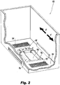
Fig. 2 is a schematic perspective view of the device ofFig. 1 , showing the recoater advancing across the build area; -
Fig. 3 is a schematic perspective view of the device ofFig. 1 , showing the recoater depositing powder in a drain beyond the build area; and -
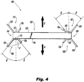
Fig. 4 is a schematic plan view of the recoater ofFig. 1 , showing the four baffles. - Reference will now be made to the drawings wherein like reference numerals identify similar structural features or aspects of the subject disclosure. For purposes of explanation and illustration, and not limitation, a partial view of an exemplary embodiment of the an additive manufacturing device in accordance with the disclosure is shown in
Fig. 1 and is designated generally byreference character 100. Other embodiments of additive manufacturing devices in accordance with the disclosure, or aspects thereof, are provided inFigs. 2-4 , as will be described. The systems and methods described herein can be used to prevent powder buildup banks lateral to the build area disrupting laminar flow of inert gas over the build area during sintering in additive manufacturing. - The
additive manufacturing device 100 includes arecoater 102 configured to push powder onto abuild area 138 of abuild platform 104. Therecoater 102 defines an advancing direction A for pushing the powder, and a returning direction R opposite the advancing direction A. Fourbaffles recoater 102. - Referring now to
Fig. 4 , thefirst baffle 106 is mounted to afirst end 114 of a leadingedge 116 of therecoater 102. Thesecond baffle 108 is mounted to asecond end 118 of the leadingedge 116 opposite thefirst end 114. Athird baffle 110 is mounted to afirst end 114 of atrailing edge 120 of therecoater 102 opposite the leadingedge 116. A fourth baffle 112 is mounted to asecond end 118 of thetrailing edge 120 of therecoater 102. - Each of the
baffles base 122 mounted to therecoater 102, afirst wall 124 that extends obliquely ahead (or behind forbaffles 110, 112) thebase 122 and laterally outward from thebase 122 relative to a respective advancing or returning direction A or R. Each of thebaffles second wall 126 opposite thefirst wall 124 that extends obliquely ahead of (or behind forbaffles 110, 112) and laterally inward from thebase 122 relative to the respective advancing or returning direction A, R. The first and second walls are each angled at an angle θ, such as 30°-60°, e.g., 45°, from the advancing or returning direction A, R of therecoater 102. The angle θ is labeled for one advancingbaffle 110 and for one returning baffle 112 inFig. 4 , however, thebaffles first wall 124 of each of thebaffles second wall 126. A volume V is defined between the first andsecond wall recoater 102 advances or returns. The volume V is indicated schematically with a broken line forbaffle 106 inFig. 4 , however thebaffles - With reference again to
Fig. 1 , thebuild platform 104 is mounted stationary relative to advancing and returning movement of therecoater 102 over thebuild platform 104. Agas inlet 128 for introducing inert gas is included on a lateral side of thebuild platform 104. Agas outlet 130 for suctioning inert gas from thebuild platform 104 is included on a lateral side of thebuild platform 104 opposite theinlet 128. Apowder drain 132 is included at one end of thebuild platform 104. Asecond powder drain 134 is included at an end of thebuild platform 104 opposite thefirst powder drain 132. The capacity in the volume V of each of thebaffles baffles 110, 112 in the returning direction R) to therespective powder drain recoater 102 to prevent buildup oflateral powder banks 136 which would otherwise grow to block flow of inert gas from thegas inlet 128 to thegas outlet 130. The powder drains 132, 134 are optional, and can be connected to a powder recycling system for reusing the powder deposited therein. InFig. 1 , thebanks 136 and their effect on the flow arrows representing the inert gas are exaggerated for the sake of clarity. - A method of additive manufacturing includes advancing a recoater (e.g. recoater 102) over a build area (e.g. build area 138) to push powder across the build area. The method includes collecting powder in a baffle (e.g. baffles 106, 108, 110, 122) mounted to an end of the recoater, depositing the collected powder from the baffle beyond the build area (e.g in powder drains 132, 134), and selectively fusing powder in the build area, e.g., with a
laser 140 as shown schematically inFig. 3 . - Collecting powder includes collecting powder in the
first baffle 106 and in asecond baffle 106, as the recoater advances across thebuild area 138 as shown inFig. 2 . As the powder collects in thebaffles Fig. 4 ) of thebaffles baffles build area 138 before overflowing and spilling out laterally. At the end of a full advancing sweep of therecoater 102, the powder from the volumes V of thebaffles powder drain 132, or optionally if nopowder drain 132 is included, at least this powder is deposited away from thebuild area 138 to avoid disrupting the inert gas flow described above. The method can include returning therecoater 102 over thebuild area 138 in the return direction R to push powder across thebuild area 138, collecting powder in the third andfourth baffles 110, 112, and depositing the collected powder beyond the build area 138 (as in the position of therecoater 102 shown inFig. 1 ), optionally into thepowder drain 134 if included. The method can include bathing thebuild area 138 in a laminar flow of inert gas, as indicated schematically by the flow arrows inFig. 3 , while selectively fusing the powder in thebuild area 138, e.g., with thelaser 140. The method can include repeating advancing therecoater 102, collecting powder, depositing the collected powder, selectively fusing powder, and bathing thebuild area 138 in a laminar flow of inert gas without building up a bank of powder along thebuild area 138, which would otherwise block the desirable uninterrupted, concentrated, laminar flow of inert gas over the build in progress in thebuild area 138. - Systems and methods as disclosed herein help ensure optical gas flow over a build stage during the melting process of additive manufacturing machines. This allows removal of condensates generated in the build process, keeps laser optics clean which is beneficial to the health of the additive manufacturing system, and enables consistent material properties throughout the parts being built.
- The methods and systems of the present disclosure, as described above and shown in the drawings, provide for recoaters with superior properties including improved powder removal from in and around the build area to improve flow of inert gas during additive manufacturing. While the apparatus and methods of the subject disclosure have been shown and described with reference to illustrated exemplary embodiments, those skilled in the art will readily appreciate that changes and/or modifications may be made thereto without departing from the scope of the invention as defined by the claims.
Claims (14)
- An additive manufacturing device comprising:a recoater (102) configured to push powder onto a build platform, the recoater defining an advancing direction for pushing powder; anda first baffle (106) mounted to a first end (114) of a leading edge (116) of the recoater and a second baffle (108) mounted to a second end (118) of the leading edge of the recoater opposite the first end, wherein each of the first and second baffles includes:a base (122) mounted to the recoater;a first wall (!24) that extends obliquely ahead of and laterally outward from the base relative to the advancing direction; anda second wall (126) opposite the first wall, the second wall extending obliquely ahead of and laterally inward from the base relative to the advancing direction, wherein a volume is defined between the first and second wall with capacity to collect powder as the recoater advances.
- The device as recited in claim 1, wherein the first and second walls are each angled 30-60° from the advancing direction of the recoater.
- The device as recited in claim 1 or 2, wherein the first wall of each of the first and second baffles is longer than the second wall thereof.
- The device as recited in any preceding claim, further comprising:a build platform (104) mounted stationary relative to advancing and returning movement of the recoater over the build platform;a gas inlet (128) for inert gas on a lateral side of the build platform; anda gas outlet (130) for inert gas on a lateral side of the build platform opposite the inlet.
- The device as recited in claim 4, further comprising:
a powder drain (132) at one end of the build platform, wherein the capacity of each of the first and second baffles is sufficient to collect and move powder in the advancing direction to the powder drain with each advance of the recoater to prevent buildup of lateral powder banks blocking flow of inert gas from the gas inlet to the gas outlet. - The device as recited in any preceding claim, further comprising:
a third baffle (110) mounted to a first end (114) of a trailing edge (120) of the recoater opposite the leading edge, and a fourth baffle (112) mounted to a second end (118) of the trailing edge of the recoater opposite the first end, wherein each of the third and fourth baffles includes:a base (122) mounted to the recoater;a first wall (124) that extends obliquely ahead of and laterally outward from the base relative to a returning direction opposite the advancing direction; anda second wall (126) opposite the first wall extending obliquely ahead of and laterally inward from the base relative to the returning direction, wherein a volume is defined between the first and second wall with capacity to collect powder as the recoater returns from advancing. - The device as recited in claim 6, wherein the first and second walls of the third and fourth baffles can each be angled 30-60° from the returning direction of the recoater.
- The device as recited in claim 6, wherein the first wall of each of the third and fourth baffles is longer than the second wall.
- The device as recited in claim 6, 7 or 8, further comprising:a first powder drain (132) at one end of the build platform, wherein the capacity of each of the first and second baffles is sufficient to collect and move powder in the advancing direction to the first powder drain with each advance of the recoater to prevent buildup of lateral powder banks blocking flow of inert gas from the gas inlet to the gas outlet; anda second powder drain (134) at an end of the build platform opposite the first powder drain, wherein the capacity of each of the third and fourth baffles is sufficient to collect and move powder in the advancing direction to the second powder drain with each advance of the recoater to prevent buildup of lateral powder banks blocking flow of inert gas from the gas inlet to the gas outlet.
- A method of additive manufacturing comprising:advancing a recoater over a build area to push powder across the build area;collecting powder in a baffle mounted to an end of the recoater;depositing the collected powder from the baffle beyond the build area; andselectively fusing powder in the build area.
- The method as recited in claim 12, wherein the baffle is a first baffle and wherein collecting powder includes collecting powder in the first baffle and in a second baffle mounted to an end of the recoater opposite the first baffle.
- The method as recited in claim 11, wherein the first and second baffles are mounted to a leading edge of the recoater and further comprising:returning the recoater over the build area to push powder across the build area;collecting powder in a third baffle mounted to an end of the recoater while returning the recoater over the build area; anddepositing the collected powder from the third baffle beyond the build area.
- The method as recited in claim 12, wherein collecting power in the third baffle includes collecting powder in a fourth baffle mounted to an end of the recoater opposite the third baffle.
- The method as recited in claim 10, 11, 12 or 13, further comprising bathing the build area in a laminar flow of inert gas while selectively fusing the powder in the build area, and repeating advancing the recoater, collecting powder, depositing the collected powder, selectively fusing powder, and bathing the build area in a laminar flow of inert gas without building up a bank of powder along the build area to block the laminar flow of inert gas.
Applications Claiming Priority (1)
| Application Number | Priority Date | Filing Date | Title |
|---|---|---|---|
| US16/258,111 US11179888B2 (en) | 2019-01-25 | 2019-01-25 | Recoaters with gas flow management |
Publications (2)
| Publication Number | Publication Date |
|---|---|
| EP3685940A1 true EP3685940A1 (en) | 2020-07-29 |
| EP3685940B1 EP3685940B1 (en) | 2023-10-04 |
Family
ID=68655359
Family Applications (1)
| Application Number | Title | Priority Date | Filing Date |
|---|---|---|---|
| EP19211190.4A Active EP3685940B1 (en) | 2019-01-25 | 2019-11-25 | Recoaters with improved powder-pushing edges |
Country Status (2)
| Country | Link |
|---|---|
| US (2) | US11179888B2 (en) |
| EP (1) | EP3685940B1 (en) |
Families Citing this family (4)
| Publication number | Priority date | Publication date | Assignee | Title |
|---|---|---|---|---|
| US10022795B1 (en) * | 2017-01-13 | 2018-07-17 | General Electric Company | Large scale additive machine |
| US11203153B2 (en) * | 2019-10-15 | 2021-12-21 | Applied Materials, Inc. | Powder bin for additive manufacturing system |
| WO2022268312A1 (en) * | 2021-06-23 | 2022-12-29 | Eos Gmbh Electro Optical Systems | Additive manufacturing apparatus and method for producing a three-dimensional object |
| CN119910207A (en) * | 2025-04-02 | 2025-05-02 | 广州瑞通增材科技有限公司 | Additive manufacturing tuyere device |
Citations (4)
| Publication number | Priority date | Publication date | Assignee | Title |
|---|---|---|---|---|
| US20150290671A1 (en) * | 2014-04-11 | 2015-10-15 | MTU Aero Engines AG | Device for the generative production of a component |
| US20160001401A1 (en) * | 2013-02-14 | 2016-01-07 | Renishaw Plc | Selective laser solidification apparatus and method |
| EP3162543A1 (en) * | 2015-10-27 | 2017-05-03 | Hamilton Sundstrand Corporation | Rake systems for additive manufacturing systems |
| EP3363566A1 (en) * | 2017-02-21 | 2018-08-22 | Renishaw PLC | Powder bed fusion apparatus |
Family Cites Families (3)
| Publication number | Priority date | Publication date | Assignee | Title |
|---|---|---|---|---|
| JPH0829821B2 (en) | 1990-02-21 | 1996-03-27 | 日立化成工業株式会社 | Device for continuously forming powder layers of uniform thickness |
| FR2802128B1 (en) | 1999-12-10 | 2002-02-08 | Ecole Nale Sup Artes Metiers | DEVICE FOR DEPOSITING THIN LAYERS OF POWDER OR POWDER MATERIAL AND METHOD THEREOF |
| DE102006023484A1 (en) * | 2006-05-18 | 2007-11-22 | Eos Gmbh Electro Optical Systems | Apparatus and method for layering a three-dimensional object from a powdery building material |
-
2019
- 2019-01-25 US US16/258,111 patent/US11179888B2/en active Active
- 2019-11-25 EP EP19211190.4A patent/EP3685940B1/en active Active
-
2021
- 2021-09-29 US US17/488,711 patent/US11701820B2/en active Active
Patent Citations (4)
| Publication number | Priority date | Publication date | Assignee | Title |
|---|---|---|---|---|
| US20160001401A1 (en) * | 2013-02-14 | 2016-01-07 | Renishaw Plc | Selective laser solidification apparatus and method |
| US20150290671A1 (en) * | 2014-04-11 | 2015-10-15 | MTU Aero Engines AG | Device for the generative production of a component |
| EP3162543A1 (en) * | 2015-10-27 | 2017-05-03 | Hamilton Sundstrand Corporation | Rake systems for additive manufacturing systems |
| EP3363566A1 (en) * | 2017-02-21 | 2018-08-22 | Renishaw PLC | Powder bed fusion apparatus |
Also Published As
| Publication number | Publication date |
|---|---|
| US11179888B2 (en) | 2021-11-23 |
| US20220016836A1 (en) | 2022-01-20 |
| US20200238607A1 (en) | 2020-07-30 |
| EP3685940B1 (en) | 2023-10-04 |
| US11701820B2 (en) | 2023-07-18 |
Similar Documents
| Publication | Publication Date | Title |
|---|---|---|
| US11701820B2 (en) | Recoaters with gas flow management | |
| US11623279B2 (en) | Recoaters with gas flow management | |
| CN103056365B (en) | The interpolation manufacturing management of body built by large part | |
| EP3221073B1 (en) | Additive manufacturing apparatus and methods | |
| US10967568B2 (en) | Additive manufacturing machine comprising a powder distribution system having a tray and an injector | |
| JPH06226855A (en) | Total containment welding equipment | |
| EP0606038B1 (en) | Edge removal apparatus for curtain coating | |
| CN109773404A (en) | A method of it is damaged that shell is repaired using electric arc increasing material manufacturing | |
| JP6128101B2 (en) | Laser cladding equipment | |
| US11772162B2 (en) | Local collection of contaminants formed during metal powder bed fusion process | |
| CN108367352A (en) | It include the increasing material manufacturing method of the powder distribution step carried out by syringe | |
| CN104148786A (en) | Method for automatic argon arc welding of titanium-molybdenum-nickel alloy thick filament with diameter of 2.0 mm | |
| FR3020584A1 (en) | METHOD AND INSTALLATION OF ARC PLASMA CUTTING WITH IMPROVED DRILLING CYCLE | |
| JP6457504B2 (en) | System and method for forming solid castings | |
| EP3501696A1 (en) | Splatter shield systems and methods for additive manufacturing | |
| CN207077106U (en) | A kind of dust arrester for being used to be cut by laser pole piece | |
| WO2016085725A1 (en) | Apparatus for manufacturing a glass ribbon | |
| CN116372352A (en) | A connection method for T-shaped joints of extra-thick steel plates | |
| JP2024042297A (en) | coolant treatment equipment | |
| WO2013151061A1 (en) | Mold for continuous casting of titanium or titanium alloy ingot, and continuous casting device provided with same | |
| JP2005211957A (en) | Laser cutting device | |
| CN110740833B (en) | Sputtering material scattering prevention device and flash butt welding machine provided with same | |
| CN220335288U (en) | Cooling cover plate structure for evaporation coating and evaporation coating device | |
| CN221735573U (en) | Machine tool coolant filter device and machine tool | |
| JPH0523947A (en) | Chip disposer |
Legal Events
| Date | Code | Title | Description |
|---|---|---|---|
| PUAI | Public reference made under article 153(3) epc to a published international application that has entered the european phase |
Free format text: ORIGINAL CODE: 0009012 |
|
| STAA | Information on the status of an ep patent application or granted ep patent |
Free format text: STATUS: THE APPLICATION HAS BEEN PUBLISHED |
|
| AK | Designated contracting states |
Kind code of ref document: A1 Designated state(s): AL AT BE BG CH CY CZ DE DK EE ES FI FR GB GR HR HU IE IS IT LI LT LU LV MC MK MT NL NO PL PT RO RS SE SI SK SM TR |
|
| AX | Request for extension of the european patent |
Extension state: BA ME |
|
| STAA | Information on the status of an ep patent application or granted ep patent |
Free format text: STATUS: REQUEST FOR EXAMINATION WAS MADE |
|
| 17P | Request for examination filed |
Effective date: 20210129 |
|
| RBV | Designated contracting states (corrected) |
Designated state(s): AL AT BE BG CH CY CZ DE DK EE ES FI FR GB GR HR HU IE IS IT LI LT LU LV MC MK MT NL NO PL PT RO RS SE SI SK SM TR |
|
| STAA | Information on the status of an ep patent application or granted ep patent |
Free format text: STATUS: EXAMINATION IS IN PROGRESS |
|
| 17Q | First examination report despatched |
Effective date: 20210906 |
|
| RAP3 | Party data changed (applicant data changed or rights of an application transferred) |
Owner name: COLLINS ENGINE NOZZLES, INC. |
|
| REG | Reference to a national code |
Ref country code: DE Ref legal event code: R079 Free format text: PREVIOUS MAIN CLASS: B22F0003000000 Ipc: B22F0010280000 Ref country code: DE Ref legal event code: R079 Ref document number: 602019038552 Country of ref document: DE Free format text: PREVIOUS MAIN CLASS: B22F0003000000 Ipc: B22F0010280000 |
|
| RIC1 | Information provided on ipc code assigned before grant |
Ipc: B22F 10/73 20210101ALN20230106BHEP Ipc: B22F 12/67 20210101ALI20230106BHEP Ipc: B29C 64/153 20170101ALI20230106BHEP Ipc: B33Y 40/00 20150101ALI20230106BHEP Ipc: B33Y 30/00 20150101ALI20230106BHEP Ipc: B33Y 10/00 20150101ALI20230106BHEP Ipc: B29C 64/371 20170101ALI20230106BHEP Ipc: B29C 64/357 20170101ALI20230106BHEP Ipc: B29C 64/321 20170101ALI20230106BHEP Ipc: B29C 64/205 20170101ALI20230106BHEP Ipc: B22F 10/28 20210101AFI20230106BHEP |
|
| GRAP | Despatch of communication of intention to grant a patent |
Free format text: ORIGINAL CODE: EPIDOSNIGR1 |
|
| STAA | Information on the status of an ep patent application or granted ep patent |
Free format text: STATUS: GRANT OF PATENT IS INTENDED |
|
| RIC1 | Information provided on ipc code assigned before grant |
Ipc: B22F 10/73 20210101ALN20230329BHEP Ipc: B22F 12/67 20210101ALI20230329BHEP Ipc: B29C 64/153 20170101ALI20230329BHEP Ipc: B33Y 40/00 20200101ALI20230329BHEP Ipc: B33Y 30/00 20150101ALI20230329BHEP Ipc: B33Y 10/00 20150101ALI20230329BHEP Ipc: B29C 64/371 20170101ALI20230329BHEP Ipc: B29C 64/357 20170101ALI20230329BHEP Ipc: B29C 64/321 20170101ALI20230329BHEP Ipc: B29C 64/205 20170101ALI20230329BHEP Ipc: B22F 10/28 20210101AFI20230329BHEP |
|
| RIC1 | Information provided on ipc code assigned before grant |
Ipc: B22F 10/73 20210101ALN20230331BHEP Ipc: B22F 12/67 20210101ALI20230331BHEP Ipc: B29C 64/153 20170101ALI20230331BHEP Ipc: B33Y 40/00 20200101ALI20230331BHEP Ipc: B33Y 30/00 20150101ALI20230331BHEP Ipc: B33Y 10/00 20150101ALI20230331BHEP Ipc: B29C 64/371 20170101ALI20230331BHEP Ipc: B29C 64/357 20170101ALI20230331BHEP Ipc: B29C 64/321 20170101ALI20230331BHEP Ipc: B29C 64/205 20170101ALI20230331BHEP Ipc: B22F 10/28 20210101AFI20230331BHEP |
|
| INTG | Intention to grant announced |
Effective date: 20230419 |
|
| RIN1 | Information on inventor provided before grant (corrected) |
Inventor name: MORGANSON, DAVID W. Inventor name: GIULIETTI, DIANA |
|
| GRAS | Grant fee paid |
Free format text: ORIGINAL CODE: EPIDOSNIGR3 |
|
| GRAA | (expected) grant |
Free format text: ORIGINAL CODE: 0009210 |
|
| STAA | Information on the status of an ep patent application or granted ep patent |
Free format text: STATUS: THE PATENT HAS BEEN GRANTED |
|
| AK | Designated contracting states |
Kind code of ref document: B1 Designated state(s): AL AT BE BG CH CY CZ DE DK EE ES FI FR GB GR HR HU IE IS IT LI LT LU LV MC MK MT NL NO PL PT RO RS SE SI SK SM TR |
|
| REG | Reference to a national code |
Ref country code: GB Ref legal event code: FG4D |
|
| REG | Reference to a national code |
Ref country code: CH Ref legal event code: EP |
|
| REG | Reference to a national code |
Ref country code: DE Ref legal event code: R096 Ref document number: 602019038552 Country of ref document: DE |
|
| REG | Reference to a national code |
Ref country code: IE Ref legal event code: FG4D |
|
| P01 | Opt-out of the competence of the unified patent court (upc) registered |
Effective date: 20230922 |
|
| REG | Reference to a national code |
Ref country code: LT Ref legal event code: MG9D |
|
| REG | Reference to a national code |
Ref country code: NL Ref legal event code: MP Effective date: 20231004 |
|
| REG | Reference to a national code |
Ref country code: AT Ref legal event code: MK05 Ref document number: 1617231 Country of ref document: AT Kind code of ref document: T Effective date: 20231004 |
|
| PG25 | Lapsed in a contracting state [announced via postgrant information from national office to epo] |
Ref country code: NL Free format text: LAPSE BECAUSE OF FAILURE TO SUBMIT A TRANSLATION OF THE DESCRIPTION OR TO PAY THE FEE WITHIN THE PRESCRIBED TIME-LIMIT Effective date: 20231004 |
|
| PG25 | Lapsed in a contracting state [announced via postgrant information from national office to epo] |
Ref country code: GR Free format text: LAPSE BECAUSE OF FAILURE TO SUBMIT A TRANSLATION OF THE DESCRIPTION OR TO PAY THE FEE WITHIN THE PRESCRIBED TIME-LIMIT Effective date: 20240105 |
|
| PG25 | Lapsed in a contracting state [announced via postgrant information from national office to epo] |
Ref country code: IS Free format text: LAPSE BECAUSE OF FAILURE TO SUBMIT A TRANSLATION OF THE DESCRIPTION OR TO PAY THE FEE WITHIN THE PRESCRIBED TIME-LIMIT Effective date: 20240204 |
|
| PG25 | Lapsed in a contracting state [announced via postgrant information from national office to epo] |
Ref country code: LT Free format text: LAPSE BECAUSE OF FAILURE TO SUBMIT A TRANSLATION OF THE DESCRIPTION OR TO PAY THE FEE WITHIN THE PRESCRIBED TIME-LIMIT Effective date: 20231004 |
|
| PG25 | Lapsed in a contracting state [announced via postgrant information from national office to epo] |
Ref country code: AT Free format text: LAPSE BECAUSE OF FAILURE TO SUBMIT A TRANSLATION OF THE DESCRIPTION OR TO PAY THE FEE WITHIN THE PRESCRIBED TIME-LIMIT Effective date: 20231004 |
|
| PG25 | Lapsed in a contracting state [announced via postgrant information from national office to epo] |
Ref country code: ES Free format text: LAPSE BECAUSE OF FAILURE TO SUBMIT A TRANSLATION OF THE DESCRIPTION OR TO PAY THE FEE WITHIN THE PRESCRIBED TIME-LIMIT Effective date: 20231004 |
|
| PG25 | Lapsed in a contracting state [announced via postgrant information from national office to epo] |
Ref country code: LT Free format text: LAPSE BECAUSE OF FAILURE TO SUBMIT A TRANSLATION OF THE DESCRIPTION OR TO PAY THE FEE WITHIN THE PRESCRIBED TIME-LIMIT Effective date: 20231004 Ref country code: IS Free format text: LAPSE BECAUSE OF FAILURE TO SUBMIT A TRANSLATION OF THE DESCRIPTION OR TO PAY THE FEE WITHIN THE PRESCRIBED TIME-LIMIT Effective date: 20240204 Ref country code: GR Free format text: LAPSE BECAUSE OF FAILURE TO SUBMIT A TRANSLATION OF THE DESCRIPTION OR TO PAY THE FEE WITHIN THE PRESCRIBED TIME-LIMIT Effective date: 20240105 Ref country code: ES Free format text: LAPSE BECAUSE OF FAILURE TO SUBMIT A TRANSLATION OF THE DESCRIPTION OR TO PAY THE FEE WITHIN THE PRESCRIBED TIME-LIMIT Effective date: 20231004 Ref country code: BG Free format text: LAPSE BECAUSE OF FAILURE TO SUBMIT A TRANSLATION OF THE DESCRIPTION OR TO PAY THE FEE WITHIN THE PRESCRIBED TIME-LIMIT Effective date: 20240104 Ref country code: AT Free format text: LAPSE BECAUSE OF FAILURE TO SUBMIT A TRANSLATION OF THE DESCRIPTION OR TO PAY THE FEE WITHIN THE PRESCRIBED TIME-LIMIT Effective date: 20231004 Ref country code: PT Free format text: LAPSE BECAUSE OF FAILURE TO SUBMIT A TRANSLATION OF THE DESCRIPTION OR TO PAY THE FEE WITHIN THE PRESCRIBED TIME-LIMIT Effective date: 20240205 |
|
| PG25 | Lapsed in a contracting state [announced via postgrant information from national office to epo] |
Ref country code: SE Free format text: LAPSE BECAUSE OF FAILURE TO SUBMIT A TRANSLATION OF THE DESCRIPTION OR TO PAY THE FEE WITHIN THE PRESCRIBED TIME-LIMIT Effective date: 20231004 Ref country code: RS Free format text: LAPSE BECAUSE OF FAILURE TO SUBMIT A TRANSLATION OF THE DESCRIPTION OR TO PAY THE FEE WITHIN THE PRESCRIBED TIME-LIMIT Effective date: 20231004 Ref country code: PL Free format text: LAPSE BECAUSE OF FAILURE TO SUBMIT A TRANSLATION OF THE DESCRIPTION OR TO PAY THE FEE WITHIN THE PRESCRIBED TIME-LIMIT Effective date: 20231004 Ref country code: NO Free format text: LAPSE BECAUSE OF FAILURE TO SUBMIT A TRANSLATION OF THE DESCRIPTION OR TO PAY THE FEE WITHIN THE PRESCRIBED TIME-LIMIT Effective date: 20240104 Ref country code: LV Free format text: LAPSE BECAUSE OF FAILURE TO SUBMIT A TRANSLATION OF THE DESCRIPTION OR TO PAY THE FEE WITHIN THE PRESCRIBED TIME-LIMIT Effective date: 20231004 Ref country code: HR Free format text: LAPSE BECAUSE OF FAILURE TO SUBMIT A TRANSLATION OF THE DESCRIPTION OR TO PAY THE FEE WITHIN THE PRESCRIBED TIME-LIMIT Effective date: 20231004 |
|
| REG | Reference to a national code |
Ref country code: CH Ref legal event code: PL |
|
| REG | Reference to a national code |
Ref country code: DE Ref legal event code: R097 Ref document number: 602019038552 Country of ref document: DE |
|
| PG25 | Lapsed in a contracting state [announced via postgrant information from national office to epo] |
Ref country code: DK Free format text: LAPSE BECAUSE OF FAILURE TO SUBMIT A TRANSLATION OF THE DESCRIPTION OR TO PAY THE FEE WITHIN THE PRESCRIBED TIME-LIMIT Effective date: 20231004 |
|
| PG25 | Lapsed in a contracting state [announced via postgrant information from national office to epo] |
Ref country code: LU Free format text: LAPSE BECAUSE OF NON-PAYMENT OF DUE FEES Effective date: 20231125 |
|
| PG25 | Lapsed in a contracting state [announced via postgrant information from national office to epo] |
Ref country code: CH Free format text: LAPSE BECAUSE OF NON-PAYMENT OF DUE FEES Effective date: 20231130 |
|
| PG25 | Lapsed in a contracting state [announced via postgrant information from national office to epo] |
Ref country code: CZ Free format text: LAPSE BECAUSE OF FAILURE TO SUBMIT A TRANSLATION OF THE DESCRIPTION OR TO PAY THE FEE WITHIN THE PRESCRIBED TIME-LIMIT Effective date: 20231004 |
|
| PG25 | Lapsed in a contracting state [announced via postgrant information from national office to epo] |
Ref country code: SK Free format text: LAPSE BECAUSE OF FAILURE TO SUBMIT A TRANSLATION OF THE DESCRIPTION OR TO PAY THE FEE WITHIN THE PRESCRIBED TIME-LIMIT Effective date: 20231004 |
|
| PG25 | Lapsed in a contracting state [announced via postgrant information from national office to epo] |
Ref country code: SM Free format text: LAPSE BECAUSE OF FAILURE TO SUBMIT A TRANSLATION OF THE DESCRIPTION OR TO PAY THE FEE WITHIN THE PRESCRIBED TIME-LIMIT Effective date: 20231004 Ref country code: SK Free format text: LAPSE BECAUSE OF FAILURE TO SUBMIT A TRANSLATION OF THE DESCRIPTION OR TO PAY THE FEE WITHIN THE PRESCRIBED TIME-LIMIT Effective date: 20231004 Ref country code: RO Free format text: LAPSE BECAUSE OF FAILURE TO SUBMIT A TRANSLATION OF THE DESCRIPTION OR TO PAY THE FEE WITHIN THE PRESCRIBED TIME-LIMIT Effective date: 20231004 Ref country code: LU Free format text: LAPSE BECAUSE OF NON-PAYMENT OF DUE FEES Effective date: 20231125 Ref country code: IT Free format text: LAPSE BECAUSE OF FAILURE TO SUBMIT A TRANSLATION OF THE DESCRIPTION OR TO PAY THE FEE WITHIN THE PRESCRIBED TIME-LIMIT Effective date: 20231004 Ref country code: EE Free format text: LAPSE BECAUSE OF FAILURE TO SUBMIT A TRANSLATION OF THE DESCRIPTION OR TO PAY THE FEE WITHIN THE PRESCRIBED TIME-LIMIT Effective date: 20231004 Ref country code: DK Free format text: LAPSE BECAUSE OF FAILURE TO SUBMIT A TRANSLATION OF THE DESCRIPTION OR TO PAY THE FEE WITHIN THE PRESCRIBED TIME-LIMIT Effective date: 20231004 Ref country code: CZ Free format text: LAPSE BECAUSE OF FAILURE TO SUBMIT A TRANSLATION OF THE DESCRIPTION OR TO PAY THE FEE WITHIN THE PRESCRIBED TIME-LIMIT Effective date: 20231004 Ref country code: CH Free format text: LAPSE BECAUSE OF NON-PAYMENT OF DUE FEES Effective date: 20231130 |
|
| REG | Reference to a national code |
Ref country code: BE Ref legal event code: MM Effective date: 20231130 |
|
| PLBE | No opposition filed within time limit |
Free format text: ORIGINAL CODE: 0009261 |
|
| STAA | Information on the status of an ep patent application or granted ep patent |
Free format text: STATUS: NO OPPOSITION FILED WITHIN TIME LIMIT |
|
| PG25 | Lapsed in a contracting state [announced via postgrant information from national office to epo] |
Ref country code: MC Free format text: LAPSE BECAUSE OF FAILURE TO SUBMIT A TRANSLATION OF THE DESCRIPTION OR TO PAY THE FEE WITHIN THE PRESCRIBED TIME-LIMIT Effective date: 20231004 |
|
| PG25 | Lapsed in a contracting state [announced via postgrant information from national office to epo] |
Ref country code: MC Free format text: LAPSE BECAUSE OF FAILURE TO SUBMIT A TRANSLATION OF THE DESCRIPTION OR TO PAY THE FEE WITHIN THE PRESCRIBED TIME-LIMIT Effective date: 20231004 |
|
| 26N | No opposition filed |
Effective date: 20240705 |
|
| REG | Reference to a national code |
Ref country code: IE Ref legal event code: MM4A |
|
| PG25 | Lapsed in a contracting state [announced via postgrant information from national office to epo] |
Ref country code: IE Free format text: LAPSE BECAUSE OF NON-PAYMENT OF DUE FEES Effective date: 20231125 |
|
| PG25 | Lapsed in a contracting state [announced via postgrant information from national office to epo] |
Ref country code: BE Free format text: LAPSE BECAUSE OF NON-PAYMENT OF DUE FEES Effective date: 20231130 |
|
| PG25 | Lapsed in a contracting state [announced via postgrant information from national office to epo] |
Ref country code: SI Free format text: LAPSE BECAUSE OF FAILURE TO SUBMIT A TRANSLATION OF THE DESCRIPTION OR TO PAY THE FEE WITHIN THE PRESCRIBED TIME-LIMIT Effective date: 20231004 |
|
| PG25 | Lapsed in a contracting state [announced via postgrant information from national office to epo] |
Ref country code: SI Free format text: LAPSE BECAUSE OF FAILURE TO SUBMIT A TRANSLATION OF THE DESCRIPTION OR TO PAY THE FEE WITHIN THE PRESCRIBED TIME-LIMIT Effective date: 20231004 Ref country code: IE Free format text: LAPSE BECAUSE OF NON-PAYMENT OF DUE FEES Effective date: 20231125 Ref country code: BE Free format text: LAPSE BECAUSE OF NON-PAYMENT OF DUE FEES Effective date: 20231130 |
|
| PG25 | Lapsed in a contracting state [announced via postgrant information from national office to epo] |
Ref country code: FI Free format text: LAPSE BECAUSE OF FAILURE TO SUBMIT A TRANSLATION OF THE DESCRIPTION OR TO PAY THE FEE WITHIN THE PRESCRIBED TIME-LIMIT Effective date: 20231004 |
|
| PG25 | Lapsed in a contracting state [announced via postgrant information from national office to epo] |
Ref country code: CY Free format text: LAPSE BECAUSE OF FAILURE TO SUBMIT A TRANSLATION OF THE DESCRIPTION OR TO PAY THE FEE WITHIN THE PRESCRIBED TIME-LIMIT; INVALID AB INITIO Effective date: 20191125 |
|
| PG25 | Lapsed in a contracting state [announced via postgrant information from national office to epo] |
Ref country code: HU Free format text: LAPSE BECAUSE OF FAILURE TO SUBMIT A TRANSLATION OF THE DESCRIPTION OR TO PAY THE FEE WITHIN THE PRESCRIBED TIME-LIMIT; INVALID AB INITIO Effective date: 20191125 |
|
| PG25 | Lapsed in a contracting state [announced via postgrant information from national office to epo] |
Ref country code: TR Free format text: LAPSE BECAUSE OF FAILURE TO SUBMIT A TRANSLATION OF THE DESCRIPTION OR TO PAY THE FEE WITHIN THE PRESCRIBED TIME-LIMIT Effective date: 20231004 |
|
| PGFP | Annual fee paid to national office [announced via postgrant information from national office to epo] |
Ref country code: DE Payment date: 20251022 Year of fee payment: 7 |
|
| PGFP | Annual fee paid to national office [announced via postgrant information from national office to epo] |
Ref country code: GB Payment date: 20251023 Year of fee payment: 7 |
|
| PGFP | Annual fee paid to national office [announced via postgrant information from national office to epo] |
Ref country code: FR Payment date: 20251022 Year of fee payment: 7 |