EP3685806A1 - Knee prosthesis and knee prosthesis component - Google Patents
Knee prosthesis and knee prosthesis component Download PDFInfo
- Publication number
- EP3685806A1 EP3685806A1 EP20152675.3A EP20152675A EP3685806A1 EP 3685806 A1 EP3685806 A1 EP 3685806A1 EP 20152675 A EP20152675 A EP 20152675A EP 3685806 A1 EP3685806 A1 EP 3685806A1
- Authority
- EP
- European Patent Office
- Prior art keywords
- platform
- bearing
- knee prosthesis
- rib
- ribs
- Prior art date
- Legal status (The legal status is an assumption and is not a legal conclusion. Google has not performed a legal analysis and makes no representation as to the accuracy of the status listed.)
- Granted
Links
Images



Classifications
-
- A—HUMAN NECESSITIES
- A61—MEDICAL OR VETERINARY SCIENCE; HYGIENE
- A61F—FILTERS IMPLANTABLE INTO BLOOD VESSELS; PROSTHESES; DEVICES PROVIDING PATENCY TO, OR PREVENTING COLLAPSING OF, TUBULAR STRUCTURES OF THE BODY, e.g. STENTS; ORTHOPAEDIC, NURSING OR CONTRACEPTIVE DEVICES; FOMENTATION; TREATMENT OR PROTECTION OF EYES OR EARS; BANDAGES, DRESSINGS OR ABSORBENT PADS; FIRST-AID KITS
- A61F2/00—Filters implantable into blood vessels; Prostheses, i.e. artificial substitutes or replacements for parts of the body; Appliances for connecting them with the body; Devices providing patency to, or preventing collapsing of, tubular structures of the body, e.g. stents
- A61F2/02—Prostheses implantable into the body
- A61F2/30—Joints
- A61F2/38—Joints for elbows or knees
- A61F2/3868—Joints for elbows or knees with sliding tibial bearing
-
- A—HUMAN NECESSITIES
- A61—MEDICAL OR VETERINARY SCIENCE; HYGIENE
- A61F—FILTERS IMPLANTABLE INTO BLOOD VESSELS; PROSTHESES; DEVICES PROVIDING PATENCY TO, OR PREVENTING COLLAPSING OF, TUBULAR STRUCTURES OF THE BODY, e.g. STENTS; ORTHOPAEDIC, NURSING OR CONTRACEPTIVE DEVICES; FOMENTATION; TREATMENT OR PROTECTION OF EYES OR EARS; BANDAGES, DRESSINGS OR ABSORBENT PADS; FIRST-AID KITS
- A61F2/00—Filters implantable into blood vessels; Prostheses, i.e. artificial substitutes or replacements for parts of the body; Appliances for connecting them with the body; Devices providing patency to, or preventing collapsing of, tubular structures of the body, e.g. stents
- A61F2/02—Prostheses implantable into the body
- A61F2/30—Joints
- A61F2/38—Joints for elbows or knees
- A61F2/3859—Femoral components
-
- A—HUMAN NECESSITIES
- A61—MEDICAL OR VETERINARY SCIENCE; HYGIENE
- A61F—FILTERS IMPLANTABLE INTO BLOOD VESSELS; PROSTHESES; DEVICES PROVIDING PATENCY TO, OR PREVENTING COLLAPSING OF, TUBULAR STRUCTURES OF THE BODY, e.g. STENTS; ORTHOPAEDIC, NURSING OR CONTRACEPTIVE DEVICES; FOMENTATION; TREATMENT OR PROTECTION OF EYES OR EARS; BANDAGES, DRESSINGS OR ABSORBENT PADS; FIRST-AID KITS
- A61F2/00—Filters implantable into blood vessels; Prostheses, i.e. artificial substitutes or replacements for parts of the body; Appliances for connecting them with the body; Devices providing patency to, or preventing collapsing of, tubular structures of the body, e.g. stents
- A61F2/02—Prostheses implantable into the body
- A61F2/30—Joints
- A61F2/38—Joints for elbows or knees
-
- A—HUMAN NECESSITIES
- A61—MEDICAL OR VETERINARY SCIENCE; HYGIENE
- A61F—FILTERS IMPLANTABLE INTO BLOOD VESSELS; PROSTHESES; DEVICES PROVIDING PATENCY TO, OR PREVENTING COLLAPSING OF, TUBULAR STRUCTURES OF THE BODY, e.g. STENTS; ORTHOPAEDIC, NURSING OR CONTRACEPTIVE DEVICES; FOMENTATION; TREATMENT OR PROTECTION OF EYES OR EARS; BANDAGES, DRESSINGS OR ABSORBENT PADS; FIRST-AID KITS
- A61F2/00—Filters implantable into blood vessels; Prostheses, i.e. artificial substitutes or replacements for parts of the body; Appliances for connecting them with the body; Devices providing patency to, or preventing collapsing of, tubular structures of the body, e.g. stents
- A61F2/02—Prostheses implantable into the body
- A61F2/30—Joints
- A61F2/38—Joints for elbows or knees
- A61F2/389—Tibial components
-
- A—HUMAN NECESSITIES
- A61—MEDICAL OR VETERINARY SCIENCE; HYGIENE
- A61F—FILTERS IMPLANTABLE INTO BLOOD VESSELS; PROSTHESES; DEVICES PROVIDING PATENCY TO, OR PREVENTING COLLAPSING OF, TUBULAR STRUCTURES OF THE BODY, e.g. STENTS; ORTHOPAEDIC, NURSING OR CONTRACEPTIVE DEVICES; FOMENTATION; TREATMENT OR PROTECTION OF EYES OR EARS; BANDAGES, DRESSINGS OR ABSORBENT PADS; FIRST-AID KITS
- A61F2/00—Filters implantable into blood vessels; Prostheses, i.e. artificial substitutes or replacements for parts of the body; Appliances for connecting them with the body; Devices providing patency to, or preventing collapsing of, tubular structures of the body, e.g. stents
- A61F2/02—Prostheses implantable into the body
- A61F2/30—Joints
- A61F2002/30001—Additional features of subject-matter classified in A61F2/28, A61F2/30 and subgroups thereof
- A61F2002/30108—Shapes
- A61F2002/3011—Cross-sections or two-dimensional shapes
- A61F2002/30112—Rounded shapes, e.g. with rounded corners
- A61F2002/30113—Rounded shapes, e.g. with rounded corners circular
- A61F2002/30116—Rounded shapes, e.g. with rounded corners circular partial circles, i.e. circular segments
-
- A—HUMAN NECESSITIES
- A61—MEDICAL OR VETERINARY SCIENCE; HYGIENE
- A61F—FILTERS IMPLANTABLE INTO BLOOD VESSELS; PROSTHESES; DEVICES PROVIDING PATENCY TO, OR PREVENTING COLLAPSING OF, TUBULAR STRUCTURES OF THE BODY, e.g. STENTS; ORTHOPAEDIC, NURSING OR CONTRACEPTIVE DEVICES; FOMENTATION; TREATMENT OR PROTECTION OF EYES OR EARS; BANDAGES, DRESSINGS OR ABSORBENT PADS; FIRST-AID KITS
- A61F2/00—Filters implantable into blood vessels; Prostheses, i.e. artificial substitutes or replacements for parts of the body; Appliances for connecting them with the body; Devices providing patency to, or preventing collapsing of, tubular structures of the body, e.g. stents
- A61F2/02—Prostheses implantable into the body
- A61F2/30—Joints
- A61F2002/30001—Additional features of subject-matter classified in A61F2/28, A61F2/30 and subgroups thereof
- A61F2002/30108—Shapes
- A61F2002/3011—Cross-sections or two-dimensional shapes
- A61F2002/30138—Convex polygonal shapes
- A61F2002/30153—Convex polygonal shapes rectangular
-
- A—HUMAN NECESSITIES
- A61—MEDICAL OR VETERINARY SCIENCE; HYGIENE
- A61F—FILTERS IMPLANTABLE INTO BLOOD VESSELS; PROSTHESES; DEVICES PROVIDING PATENCY TO, OR PREVENTING COLLAPSING OF, TUBULAR STRUCTURES OF THE BODY, e.g. STENTS; ORTHOPAEDIC, NURSING OR CONTRACEPTIVE DEVICES; FOMENTATION; TREATMENT OR PROTECTION OF EYES OR EARS; BANDAGES, DRESSINGS OR ABSORBENT PADS; FIRST-AID KITS
- A61F2/00—Filters implantable into blood vessels; Prostheses, i.e. artificial substitutes or replacements for parts of the body; Appliances for connecting them with the body; Devices providing patency to, or preventing collapsing of, tubular structures of the body, e.g. stents
- A61F2/02—Prostheses implantable into the body
- A61F2/30—Joints
- A61F2002/30001—Additional features of subject-matter classified in A61F2/28, A61F2/30 and subgroups thereof
- A61F2002/30316—The prosthesis having different structural features at different locations within the same prosthesis; Connections between prosthetic parts; Special structural features of bone or joint prostheses not otherwise provided for
- A61F2002/30329—Connections or couplings between prosthetic parts, e.g. between modular parts; Connecting elements
-
- A—HUMAN NECESSITIES
- A61—MEDICAL OR VETERINARY SCIENCE; HYGIENE
- A61F—FILTERS IMPLANTABLE INTO BLOOD VESSELS; PROSTHESES; DEVICES PROVIDING PATENCY TO, OR PREVENTING COLLAPSING OF, TUBULAR STRUCTURES OF THE BODY, e.g. STENTS; ORTHOPAEDIC, NURSING OR CONTRACEPTIVE DEVICES; FOMENTATION; TREATMENT OR PROTECTION OF EYES OR EARS; BANDAGES, DRESSINGS OR ABSORBENT PADS; FIRST-AID KITS
- A61F2/00—Filters implantable into blood vessels; Prostheses, i.e. artificial substitutes or replacements for parts of the body; Appliances for connecting them with the body; Devices providing patency to, or preventing collapsing of, tubular structures of the body, e.g. stents
- A61F2/02—Prostheses implantable into the body
- A61F2/30—Joints
- A61F2002/30001—Additional features of subject-matter classified in A61F2/28, A61F2/30 and subgroups thereof
- A61F2002/30316—The prosthesis having different structural features at different locations within the same prosthesis; Connections between prosthetic parts; Special structural features of bone or joint prostheses not otherwise provided for
- A61F2002/30329—Connections or couplings between prosthetic parts, e.g. between modular parts; Connecting elements
- A61F2002/30383—Connections or couplings between prosthetic parts, e.g. between modular parts; Connecting elements made by laterally inserting a protrusion, e.g. a rib into a complementarily-shaped groove
-
- A—HUMAN NECESSITIES
- A61—MEDICAL OR VETERINARY SCIENCE; HYGIENE
- A61F—FILTERS IMPLANTABLE INTO BLOOD VESSELS; PROSTHESES; DEVICES PROVIDING PATENCY TO, OR PREVENTING COLLAPSING OF, TUBULAR STRUCTURES OF THE BODY, e.g. STENTS; ORTHOPAEDIC, NURSING OR CONTRACEPTIVE DEVICES; FOMENTATION; TREATMENT OR PROTECTION OF EYES OR EARS; BANDAGES, DRESSINGS OR ABSORBENT PADS; FIRST-AID KITS
- A61F2/00—Filters implantable into blood vessels; Prostheses, i.e. artificial substitutes or replacements for parts of the body; Appliances for connecting them with the body; Devices providing patency to, or preventing collapsing of, tubular structures of the body, e.g. stents
- A61F2/02—Prostheses implantable into the body
- A61F2/30—Joints
- A61F2002/30001—Additional features of subject-matter classified in A61F2/28, A61F2/30 and subgroups thereof
- A61F2002/30316—The prosthesis having different structural features at different locations within the same prosthesis; Connections between prosthetic parts; Special structural features of bone or joint prostheses not otherwise provided for
- A61F2002/30329—Connections or couplings between prosthetic parts, e.g. between modular parts; Connecting elements
- A61F2002/30383—Connections or couplings between prosthetic parts, e.g. between modular parts; Connecting elements made by laterally inserting a protrusion, e.g. a rib into a complementarily-shaped groove
- A61F2002/30385—Connections or couplings between prosthetic parts, e.g. between modular parts; Connecting elements made by laterally inserting a protrusion, e.g. a rib into a complementarily-shaped groove the rib and groove having non-parallel, e.g. conically-tapered, cooperating sides, e.g. having a trapezoidal front cross-section
-
- A—HUMAN NECESSITIES
- A61—MEDICAL OR VETERINARY SCIENCE; HYGIENE
- A61F—FILTERS IMPLANTABLE INTO BLOOD VESSELS; PROSTHESES; DEVICES PROVIDING PATENCY TO, OR PREVENTING COLLAPSING OF, TUBULAR STRUCTURES OF THE BODY, e.g. STENTS; ORTHOPAEDIC, NURSING OR CONTRACEPTIVE DEVICES; FOMENTATION; TREATMENT OR PROTECTION OF EYES OR EARS; BANDAGES, DRESSINGS OR ABSORBENT PADS; FIRST-AID KITS
- A61F2/00—Filters implantable into blood vessels; Prostheses, i.e. artificial substitutes or replacements for parts of the body; Appliances for connecting them with the body; Devices providing patency to, or preventing collapsing of, tubular structures of the body, e.g. stents
- A61F2/02—Prostheses implantable into the body
- A61F2/30—Joints
- A61F2002/30001—Additional features of subject-matter classified in A61F2/28, A61F2/30 and subgroups thereof
- A61F2002/30316—The prosthesis having different structural features at different locations within the same prosthesis; Connections between prosthetic parts; Special structural features of bone or joint prostheses not otherwise provided for
- A61F2002/30329—Connections or couplings between prosthetic parts, e.g. between modular parts; Connecting elements
- A61F2002/30383—Connections or couplings between prosthetic parts, e.g. between modular parts; Connecting elements made by laterally inserting a protrusion, e.g. a rib into a complementarily-shaped groove
- A61F2002/30387—Dovetail connection
-
- A—HUMAN NECESSITIES
- A61—MEDICAL OR VETERINARY SCIENCE; HYGIENE
- A61F—FILTERS IMPLANTABLE INTO BLOOD VESSELS; PROSTHESES; DEVICES PROVIDING PATENCY TO, OR PREVENTING COLLAPSING OF, TUBULAR STRUCTURES OF THE BODY, e.g. STENTS; ORTHOPAEDIC, NURSING OR CONTRACEPTIVE DEVICES; FOMENTATION; TREATMENT OR PROTECTION OF EYES OR EARS; BANDAGES, DRESSINGS OR ABSORBENT PADS; FIRST-AID KITS
- A61F2/00—Filters implantable into blood vessels; Prostheses, i.e. artificial substitutes or replacements for parts of the body; Appliances for connecting them with the body; Devices providing patency to, or preventing collapsing of, tubular structures of the body, e.g. stents
- A61F2/02—Prostheses implantable into the body
- A61F2/30—Joints
- A61F2002/30001—Additional features of subject-matter classified in A61F2/28, A61F2/30 and subgroups thereof
- A61F2002/30316—The prosthesis having different structural features at different locations within the same prosthesis; Connections between prosthetic parts; Special structural features of bone or joint prostheses not otherwise provided for
- A61F2002/30329—Connections or couplings between prosthetic parts, e.g. between modular parts; Connecting elements
- A61F2002/30476—Connections or couplings between prosthetic parts, e.g. between modular parts; Connecting elements locked by an additional locking mechanism
- A61F2002/305—Snap connection
-
- A—HUMAN NECESSITIES
- A61—MEDICAL OR VETERINARY SCIENCE; HYGIENE
- A61F—FILTERS IMPLANTABLE INTO BLOOD VESSELS; PROSTHESES; DEVICES PROVIDING PATENCY TO, OR PREVENTING COLLAPSING OF, TUBULAR STRUCTURES OF THE BODY, e.g. STENTS; ORTHOPAEDIC, NURSING OR CONTRACEPTIVE DEVICES; FOMENTATION; TREATMENT OR PROTECTION OF EYES OR EARS; BANDAGES, DRESSINGS OR ABSORBENT PADS; FIRST-AID KITS
- A61F2/00—Filters implantable into blood vessels; Prostheses, i.e. artificial substitutes or replacements for parts of the body; Appliances for connecting them with the body; Devices providing patency to, or preventing collapsing of, tubular structures of the body, e.g. stents
- A61F2/02—Prostheses implantable into the body
- A61F2/30—Joints
- A61F2002/30001—Additional features of subject-matter classified in A61F2/28, A61F2/30 and subgroups thereof
- A61F2002/30316—The prosthesis having different structural features at different locations within the same prosthesis; Connections between prosthetic parts; Special structural features of bone or joint prostheses not otherwise provided for
- A61F2002/30535—Special structural features of bone or joint prostheses not otherwise provided for
- A61F2002/30604—Special structural features of bone or joint prostheses not otherwise provided for modular
- A61F2002/30616—Sets comprising a plurality of prosthetic parts of different sizes or orientations
-
- A—HUMAN NECESSITIES
- A61—MEDICAL OR VETERINARY SCIENCE; HYGIENE
- A61F—FILTERS IMPLANTABLE INTO BLOOD VESSELS; PROSTHESES; DEVICES PROVIDING PATENCY TO, OR PREVENTING COLLAPSING OF, TUBULAR STRUCTURES OF THE BODY, e.g. STENTS; ORTHOPAEDIC, NURSING OR CONTRACEPTIVE DEVICES; FOMENTATION; TREATMENT OR PROTECTION OF EYES OR EARS; BANDAGES, DRESSINGS OR ABSORBENT PADS; FIRST-AID KITS
- A61F2/00—Filters implantable into blood vessels; Prostheses, i.e. artificial substitutes or replacements for parts of the body; Appliances for connecting them with the body; Devices providing patency to, or preventing collapsing of, tubular structures of the body, e.g. stents
- A61F2/02—Prostheses implantable into the body
- A61F2/30—Joints
- A61F2/30767—Special external or bone-contacting surface, e.g. coating for improving bone ingrowth
- A61F2/30771—Special external or bone-contacting surface, e.g. coating for improving bone ingrowth applied in original prostheses, e.g. holes or grooves
- A61F2002/30878—Special external or bone-contacting surface, e.g. coating for improving bone ingrowth applied in original prostheses, e.g. holes or grooves with non-sharp protrusions, for instance contacting the bone for anchoring, e.g. keels, pegs, pins, posts, shanks, stems, struts
-
- A—HUMAN NECESSITIES
- A61—MEDICAL OR VETERINARY SCIENCE; HYGIENE
- A61F—FILTERS IMPLANTABLE INTO BLOOD VESSELS; PROSTHESES; DEVICES PROVIDING PATENCY TO, OR PREVENTING COLLAPSING OF, TUBULAR STRUCTURES OF THE BODY, e.g. STENTS; ORTHOPAEDIC, NURSING OR CONTRACEPTIVE DEVICES; FOMENTATION; TREATMENT OR PROTECTION OF EYES OR EARS; BANDAGES, DRESSINGS OR ABSORBENT PADS; FIRST-AID KITS
- A61F2230/00—Geometry of prostheses classified in groups A61F2/00 - A61F2/26 or A61F2/82 or A61F9/00 or A61F11/00 or subgroups thereof
- A61F2230/0063—Three-dimensional shapes
-
- A—HUMAN NECESSITIES
- A61—MEDICAL OR VETERINARY SCIENCE; HYGIENE
- A61F—FILTERS IMPLANTABLE INTO BLOOD VESSELS; PROSTHESES; DEVICES PROVIDING PATENCY TO, OR PREVENTING COLLAPSING OF, TUBULAR STRUCTURES OF THE BODY, e.g. STENTS; ORTHOPAEDIC, NURSING OR CONTRACEPTIVE DEVICES; FOMENTATION; TREATMENT OR PROTECTION OF EYES OR EARS; BANDAGES, DRESSINGS OR ABSORBENT PADS; FIRST-AID KITS
- A61F2310/00—Prostheses classified in A61F2/28 or A61F2/30 - A61F2/44 being constructed from or coated with a particular material
- A61F2310/00005—The prosthesis being constructed from a particular material
- A61F2310/00011—Metals or alloys
- A61F2310/00029—Cobalt-based alloys, e.g. Co-Cr alloys or Vitallium
Definitions
- the traditional knee prosthesis mainly includes a femoral component for combining with the femur, a tibial component for combining with the tibia, and a bearing provided on the upper surface of the tibial component.
- a femoral component for combining with the femur
- a tibial component for combining with the tibia
- a bearing provided on the upper surface of the tibial component.
- a fixing groove is usually formed along the edge contour of the central protrusion of the tibial component platform to guide or position, and an elastic latch and the fixing groove are provided at the front and the back of the bearing component to achieve the purpose of locking.
- the first inclined surface and the upper surface of the platform form an intersection line, an included angle ⁇ between the intersection line and a central axis of the platform along a front-back direction is greater than 0 degree.
- the included angle ⁇ ranges from 2 degrees to 70 degrees.
- the knee prosthesis further includes a pair of the ribs wherein the pair of ribs are disposed at the middle of the upper surface of the platform, at least one of the pair of ribs is parallel or at an angle of greater than 0 relative to a central axis of the platform along a front-back direction.
- the bent portion is provided with a notch, and the notch extends upward from the upper surface of the platform and terminates at an upper surface of the rib.
- the at least one rib and the groove are interference fit in a width direction of the groove.
- the at least one back undercut is located in the middle of a back edge of the platform.
- the upper surface 201 of the bearing 20 includes a lateral support surface and a medial support surface, which are respectively articulated to the lateral condyle surface and the medial condyle surface of the femoral component 30.
- patella components may also be included, which will not be described in detail here.
- the tibial component 10 and the femoral component 30 may be made of a metal such as a cobalt chromium alloy, of course, other materials commonly used in the art may also be used.
- the bone-engaging surfaces of the tibial component 10 and the femoral component 30 can be textured to facilitate the bonding with the bone. In addition, these bone-engaging surfaces may also have a porous coating to promote bone endogenesis and thus permanently fix to the bone.
- the number of the ribs 120 may be one, two or more.
- at least one of the ribs 120 has a medial wall 121 and a lateral wall 122, in a direction which the ribs 120 extend forward, one of the medial walls 121 or the lateral wall 122 has a bent portion and forms a first inclined surface 1211, the first inclined surface 1211 extends in a direction away from the other wall of the same rib.
- the lower surface of the bearing 20 has a groove 210 matching the rib 120.
- the medial wall 121 and the lateral wall 122 of the rib 120 are inclined in the up-down direction.
- the knee prosthesis provided by the present disclosure has a structural design of "one of the medial walls 121 or the lateral walls 122 of the ribs 120 has a bend portion and forms a first inclined surface 1211, and the first inclined surface 1211 extends in a direction away from the other wall of the same rib", so that the medial wall 121 and/or the lateral wall 122 of the rib 120 have a inclined surface, the groove 210 also has an inclined surface at a corresponding position. Because the rib and the groove form an inclined surface fit, when the bearing is subjected a forward shearing force, the fit is gap free, The rib 120 effectively prevents the bearing 20 from moving forward, and significantly reduces the occurrence of micro movement between the bearing 20 and the tibial component 10.
- the specific shape of the notch 123 is not particularly limited.
- the cross-sectional shape of the notch 123 may be semicircular, rectangular, or other shapes that allow the sharp corner of the groove 210 to be received in the notch 123 without interfering therewith.
- the present disclosure also provides a knee prosthesis component, which includes one or more tibial components 10 of any one of the embodiments described above, a plurality of bearings 20 of any one of the embodiments described above, and a plurality of femoral components 30, connection relationship among the three is the same as the above, which is not repeated here, and the widths of the plurality of bearings 20 in the medial-lateral direction D2 are different.
Landscapes
- Health & Medical Sciences (AREA)
- Orthopedic Medicine & Surgery (AREA)
- Physical Education & Sports Medicine (AREA)
- Cardiology (AREA)
- Oral & Maxillofacial Surgery (AREA)
- Transplantation (AREA)
- Engineering & Computer Science (AREA)
- Biomedical Technology (AREA)
- Heart & Thoracic Surgery (AREA)
- Vascular Medicine (AREA)
- Life Sciences & Earth Sciences (AREA)
- Animal Behavior & Ethology (AREA)
- General Health & Medical Sciences (AREA)
- Public Health (AREA)
- Veterinary Medicine (AREA)
- Prostheses (AREA)
Abstract
Description
- The present disclosure relates to an implantable orthopedic prosthesis in general, and in particular, to a knee prosthesis and a knee prosthesis component.
- The concept of knee prosthesis design is generally based on a same principle, that is, the implanted knee element provides a biomechanical motion pattern similar to a normal knee, and obtains static and dynamic stability by means of the balance between the implant itself and the ligament and the soft tissue of the knee. These knee element designs all attempt to restore natural movement of human knee, and adjust and control the forces generated in the knee movement during flexing and stretching. However, all current knee prosthesis designs do not meet this standard.
- The traditional knee prosthesis mainly includes a femoral component for combining with the femur, a tibial component for combining with the tibia, and a bearing provided on the upper surface of the tibial component. Where in the fixed bearing type knee prosthesis, after the bearing is disposed on the tibial component, the bearing can't slide relative to the tibial component.
- In the related art, a fixing groove is usually formed along the edge contour of the central protrusion of the tibial component platform to guide or position, and an elastic latch and the fixing groove are provided at the front and the back of the bearing component to achieve the purpose of locking.
- However, during the use of the knee prosthesis, the direction of the stress is mainly relative to the front and back of the patient, so the forward shearing force of the bearing is greater than that of the left and right sides, as a result, the bearing will move forward slightly and be worn out due to the frequent relative sliding. The locking structure in the above related art is likely to cause stress concentration in the contact area between the bearing and the tibial edge contour, resulting in insufficient locking force to offset the shearing force of the forward movement of the bearing, thereby causing an increase in the micro-momentum and serious wear of the lower surface of the bearing.
- The above information disclosed in the background section is only used to enhance the understanding of the background of the present disclosure, so it may include information that does not constitute related technology known to those of ordinary skill in the art.
- A main object of the present disclosure is to overcome at least one of the disadvantages of the related art and provide a knee prosthesis which can reduce the slight movement of the bearing.
- Another main objective of the present disclosure is to overcome at least one of the disadvantages of the related art and provide a knee prosthesis component.
- In order to achieve the above-mentioned objects, the present disclosure adopts the following technical solutions.
- According to one aspect of the disclosure, a knee prosthesis is provided, which includes a tibial component, a bearing and a femoral component. The tibial component, comprises a platform and at least one rib extending upwardly from an upper surface of the platform and forwardly from the rear of the platform, a front edge of the upper surface of the platform is provided with at least one front lug boss, and a back edge of the upper surface of the platform is provide with at least one back lug boss; a lower surface of the bearing is provided with a groove matching with the at least one rib, and the bearing is provided with a front slot matching with the front lug boss and provided with a back slot matching with back lug boss; and the femoral component is articulated with an upper surface of the bearing; where, at least one of the ribs is provided with a medial wall and a lateral wall, at least one of the media wall or the lateral wall is provided with a bent portion and formed with a first inclined surface; when there are at least two ribs, one of plurality of medial or lateral walls is provided with a bent portion and formed with a first inclined surface and the first inclined surface extends in a direction away from the other wall in the same rib.
- According to one embodiment of the present disclosure, the first inclined surface and the upper surface of the platform form an intersection line, an included angle β between the intersection line and a central axis of the platform along a front-back direction is greater than 0 degree.
- According to one embodiment of the present disclosure, the included angle β ranges from 2 degrees to 70 degrees.
- According to one embodiment of the present disclosure, the knee prosthesis further includes a pair of the ribs wherein the pair of ribs are disposed at the middle of the upper surface of the platform, at least one of the pair of ribs is parallel or at an angle of greater than 0 relative to a central axis of the platform along a front-back direction.
- According to one embodiment of the present disclosure, the bent portion is provided with a notch, and the notch extends upward from the upper surface of the platform and terminates at an upper surface of the rib.
- According to one embodiment of the present disclosure, the tibial component includes a platform and at least one rib extending upwardly from an upper surface of the platform and forwardly from the rear of the platform, a front edge of the upper surface of the platform is provided with at least one front lug boss, and a back edge of the upper surface of the platform is provide with at least one back lug boss; a lower surface of the bearing is provided with a groove matching with the at least one rib, and the bearing is provided with a front slot matching with the front lug boss and a back slot matching with back lug boss; and the femoral component articulated with an upper surface of the bearing; wherein the at least one rib is provided with a medial wall and a lateral wall, wherein at least one of the media wall or the lateral wall is provided with a bent portion and formed with a first inclined surface and the other wall of the same rib is not provided with a bent portion; the first inclined surface extends in a direction away from the other wall of same rib, in one embodiment, the first inclined surface and the upper surface of the platform form an intersection line, an included angle between the intersection line and a central axis of the platform along a front-back direction is greater than 0 degree, for example, the included angle ranges from 2 degrees to 70 degrees; or
- the other wall of the same rib is provided with a bent portion in a forward or backward extending direction and it is formed with a second inclined surface, and wherein the second inclined surface and the first inclined surface are either parallel or angled relative to each other.
- According to one embodiment of the present disclosure, the at least one rib and the groove are interference fit in a width direction of the groove.
- According to one embodiment of the present disclosure, the front lug boss is provided with at least one front undercut, the back lug boss is provided with at least one back undercut, and the lower surface of the bearing is provided with at least one front projection snapped into the front undercut and at least one back projection snapped into the back undercut.
- According to one embodiment of the present disclosure, the at least one back undercut is located in the middle of a back edge of the platform.
- According to another aspect of the present disclosure, a knee prosthesis component is provided, which includes one or more tibial components described above, a plurality of bearings described above. Each the bearing has a different width in a medial-lateral direction; the femoral components are articulated with an upper surface of the bearing.
- It can be known from the above technical solutions that the advantages and positive effects of the knee prosthesis of the present disclosure are:
- The knee prosthesis provided by the present disclosure has a structural design of "one of the medial walls or the lateral walls of the ribs has a bend portion and forms a first inclined surface, and the first inclined surface extends in a direction away from the other wall of the same rib", so that the medial wall and/or the lateral wall of the rib have a inclined surface, the groove also has an inclined surface at a corresponding position. Because the rib and the groove form an inclined surface fit, when the bearing is subjected a forward shearing force, the fit is gap free, the rib effectively prevents the bearing from moving forward, and significantly reduces the occurrence of micro movement between the bearing and the tibial component. At the same time, according to the principle of trigonometric function, the inclined surface of the rib will resolve the forward stress of the bearing into a part of the stress in a non-forward direction, effectively reducing the forward shearing force of the bearing and reducing the tendency of the bearing to slide forward. According to this, the inclined surface fit of the rib and the groove effectively hinders the forward sliding of the bearing, reduces the micro-momentum of the bearing, and effectively reduces the wear of the lower surface of the bearing.
- The above and other features and advantages of the present disclosure will become more apparent by describing the example embodiments in detail with reference to the accompanying drawings.
-
FIG. 1 is an exploded view showing a knee prosthesis according to an exemplary embodiment. -
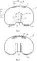
FIG. 2 is a top view showing a tibial component according to an exemplary embodiment. -
FIG. 3 is a bottom view showing a bearing according to an exemplary embodiment. -
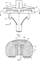
FIG. 4 is a rear view showing an assembly of a tibial component and a bearing according to an exemplary embodiment. -
FIG. 5 is a cross-sectional view taken along the line A-A inFIG. 4 . -
FIG. 6 is a cross-sectional view taken along the line B-B inFIG. 4 . -
FIG. 7 is a perspective view showing a tibial component according to another exemplary embodiment. -
Fig. 8 is a perspective view showing a tibial component according to another exemplary embodiment. -
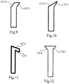
FIG. 9 is a schematic diagram showing a shape of a rib of a tibial component according to an exemplary embodiment. -
FIG. 10 is a schematic diagram showing a shape of a rib of a tibial component according to another exemplary embodiment. -
FIG. 11 is a schematic diagram showing a shape of a rib of a tibial component according to a further exemplary embodiment. -
FIG. 12 is a schematic diagram showing a shape of a rib of a tibial component according to a further embodiment. - Among them, the reference signs are described as follows:
- 10. tibial component
- 101. front edge
- 102. back edge
- 110. platform
- 111. upper surface of the platform
- 120. rib
- 121. medial wall
- 1211. first inclined surface
- 1212. intersection line
- 1213. second inclined surface
- 122. lateral wall
- 123. notch
- 130. front lug boss
- 1301. front undercut
- 140. back lug boss
- 1401. back undercut
- 20. bearing
- 201. upper surface of the bearing
- 210. groove
- 220. front slot
- 2201. front projection
- 230. back slot
- 30. femoral component
- D1. front-back direction
- D2. medial-lateral direction
- W. width direction
- X. central axis of the platform along a front-back direction
- Example embodiments will now be described more fully with reference to the accompanying drawings. However, the exemplary embodiments can be implemented in various forms and should not be construed as limited to the embodiments set forth herein; rather, these embodiments are provided so that this disclosure will be thorough and complete, and will fully convey the concept of example embodiments to those skilled in the art. The same reference numerals in the drawings denote the same or similar structures, and thus their detailed descriptions will be omitted.
- In the present disclosure, the directions such as "front", "back", "up", "down", "medial" and "lateral" are respectively consistent with the "front", "back", "up", "down", "medial" and "lateral" directions of a knee prosthesis in the situation of a person standing after the knee prosthesis is implanted in the human body, and the present disclosure is described by taking the knee prosthesis of the left knee as an example, for example, as shown in
FIG. 2 , the right side of the tibial component is medial, and the left side of the tibial component is lateral, the upper side of the tital component is front, and the lower side of the tital component is back. As the arrows shown inFIG. 2 , M indicates a medial (inward) direction, L indicates a lateral (outward) direction, F indicates a front direction and B indicates a back direction. - In the following, some embodiments of the present disclosure will be described in detail with reference to the drawings. In the case of no conflict, the features in the following embodiments can be combined with each other.
-
FIG. 1 is an exploded view showing a knee prosthesis according to an exemplary embodiment.FIG. 2 is a top view showing a tibial component according to an exemplary embodiment.FIG. 3 is a bottom view showing a bearing according to an exemplary embodiment.FIG. 4 is a rear view showing an assembly of a tibial component and a bearing according to an exemplary embodiment.FIG. 5 is a cross-sectional view taken along the line A-A inFIG. 4 .FIG. 6 is a cross-sectional view taken along the line B-B inFIG. 4 .FIG. 7 is a perspective view showing a tibial component according to another exemplary embodiment.Fig. 8 is a perspective view showing a tibial component according to a further embodiment.FIGS. 9 to 11 are schematic diagrams showing different shapes of ribs of tibial components according to exemplary embodiments. - As shown in
FIG. 1 , the present disclosure provides a knee prosthesis, which includes atibial component 10, abearing 20, and afemoral component 30. In one embodiment, thetibial component 10 includes aplatform 110 and a fixing component located on the lower surface of theplatform 110 and extend downward, such as an elongated rod, which can be implanted into the tibial of a patient by surgery (not shown). Thebearing 20 may be fixed on the upper surface of thetibial component 10, such as the cooperation between theribs 120 and thegrooves 210 as described below. Thefemoral component 30 can be implanted into the femur of a patient by surgery (not shown), and configured to follow the patient's natural femoral condyle configuration. Theupper surface 201 of thebearing 20 includes a lateral support surface and a medial support surface, which are respectively articulated to the lateral condyle surface and the medial condyle surface of thefemoral component 30. Of course, as is well known to those skilled in the art, patella components may also be included, which will not be described in detail here. - The
tibial component 10 and thefemoral component 30 may be made of a metal such as a cobalt chromium alloy, of course, other materials commonly used in the art may also be used. The bone-engaging surfaces of thetibial component 10 and thefemoral component 30 can be textured to facilitate the bonding with the bone. In addition, these bone-engaging surfaces may also have a porous coating to promote bone endogenesis and thus permanently fix to the bone. - The
bearing 20 may be made of a polymeric material, such as ultra-high molecular weight polyethylene (UHMWPE), but is not limited thereto. - The structures of the
tibial component 10 and thebearing 20 will be described in detail below with reference to the drawings - As shown in
FIGS. 1 ,2 and 3 , thetibial component 10 includes aplatform 110 and one ormore ribs 120 extending upwardly from anupper surface 111 of theplatform 110 and forwardly from aback edge 102 of theplatform 110. Therib 120 may be integrally formed with theplatform 110, for example, by milling. The size of theplatform 110 may be in accordance with the shape of the patient's tibia after the top portion is surgically cut off, so that the lower surface of theplatform 110 better matches the cross section of the tibia of the patient. - In other embodiments of the present disclosure, as shown in
FIGS. 7 and8 , one ormore ribs 120 start at the back of theplatform 110 and extend forward, and are not connected to theback edge 102 of theplatform 110, as long as it can play a role in guiding and positioning. - The number of the
ribs 120 may be one, two or more. In one embodiment, at least one of theribs 120 has amedial wall 121 and alateral wall 122, in a direction which theribs 120 extend forward, one of themedial walls 121 or thelateral wall 122 has a bent portion and forms a firstinclined surface 1211, the firstinclined surface 1211 extends in a direction away from the other wall of the same rib. The lower surface of thebearing 20 has agroove 210 matching therib 120. - Specifically, in order to facilitate the following description, take the
medial wall 121 with a bent portion as an example. As the right rib shown inFIG. 2 , themedial wall 121 extends forward and inward to form a firstinclined surface 1211, and the firstinclined surface 1211 forms an angle with the rest of themedial wall 121. The firstinclined surface 1211 is inclined inward in a forward extending direction, that is, away from thelateral wall 122. It should be noted that the "away from the other wall" in the present disclosure is away from a non-bent portion of the other wall of the same rib, if the other wall also has a bent portion in a forward extending direction and form the second inclined surface, when the first and the second inclined surface have the same bending direction (inward or outward), the first and the second inclined surface may be parallel or intersect shown inFIG. 9 to 10 . If two walls have the bent portions in a backward extending direction, the first and the second inclined surface form a shape inFIG. 11 . In other words, if the other wall (the media wall or the lateral wall) has a bent portion, the present disclosure does not specifically limit the bending direction of the bent portion, the bending direction may extend lateral or medial. When the first and the second inclined surface have the different bending direction, the width of rib gradually increases, as shown inFIG. 12 . It should be understood that the above-mentioned various modifications are all within the protection scope of the present disclosure. - In addition, the
front edge 101 of theupper surface 111 of theplatform 110 is provided with at least onefront lug boss 130, theback edge 102 of theupper surface 111 of theplatform 110 is provided with at least oneback lug boss 140. Accordingly, thebearing 20 has afront slot 220 matching thefront lug boss 130 and aback slot 230 matching theback lug boss 140. When thebearing 20 is fixedly mounted on theupper surface 111 of theplatform 110 of thetibial component 10, thefront lug boss 130 may be fitted with thefront slot 220, and theback lug boss 140 may be fitted with theback slot 230. - In the present disclosure, it is not limited whether the
medial wall 121 and thelateral wall 122 of therib 120 are inclined in the up-down direction. - During the use of the knee prosthesis, since the force direction of the patient's knee joint during flexion and extension is mainly relative to the patient's front-back direction D1, the forward shearing force of the
bearing 20 is greater than the medial and the lateral, as a result, the bearing 20 will move forward slightly and be worn due to frequent relative sliding. The knee prosthesis provided by the present disclosure has a structural design of "one of themedial walls 121 or thelateral walls 122 of theribs 120 has a bend portion and forms a firstinclined surface 1211, and the firstinclined surface 1211 extends in a direction away from the other wall of the same rib", so that themedial wall 121 and/or thelateral wall 122 of therib 120 have a inclined surface, thegroove 210 also has an inclined surface at a corresponding position. Because the rib and the groove form an inclined surface fit, when the bearing is subjected a forward shearing force, the fit is gap free, Therib 120 effectively prevents the bearing 20 from moving forward, and significantly reduces the occurrence of micro movement between the bearing 20 and thetibial component 10. At the same time, according to the principle of trigonometric function, the inclined surface of therib 120 will decompose the forward force of thebearing 20 into a part of the force in a non-forward direction, effectively reducing the forward shearing force of thebearing 20 and reducing the tendency of thebearing 20 to slide forward. According to this, the inclined surface fit of therib 120 and thegroove 210 effectively hinders the forward sliding of thebearing 20, reduces the micro-momentum of thebearing 20, and effectively reduces the wear of the lower surface of thebearing 20. - Please continue to refer to
FIGS. 1 to 3 and8 . In an embodiment of the present disclosure, the firstinclined surface 1211 and theupper surface 111 of theplatform 110 form anintersection line 1212, an included angle β between theintersection line 1212 and the central axis X of theplatform 110 along the front-back direction D1 is greater than 0 degree. For example, as shown inFIGS. 1 to 11 , the included angle β may be 0 degrees to 90 degrees, and in one embodiment, the included angle β may be 2 degrees to 70 degrees. In addition, as with the shape shown inFIG. 11 , the included angle may also be 90 degrees to 180 degrees. - Please continue to refer to
FIGS. 1 to 3 . In an embodiment of the present disclosure, there are a pair of theribs 120 disposed at the middle of theupper surface 111 of theplatform 110. The arrangement of the tworibs 120 makes the reaction force given to thebearing 20 by theribs 120 more uniform, stable, and powerful. - In other embodiments, the pair of
ribs 120 may be disposed axially symmetrically with the center axis X of theplatform 110 along the front-back direction D1. - It should be understood that the two
ribs 120 described above may have substantially the same height, or may have different heights. Among them, the term "approximately" means covering any minor change. There will be errors in measurement and assembly, but this kind of error will not change its essence. - In one embodiment, the
ribs 120 may be parallel to the central axis X of theplatform 110 along the front-back direction D1, and therib 120 may also be at an angle to the center axis X of theplatform 110 along the front-back direction D1, for example, an acute angle. Of course, the tworibs 120 may be parallel to the central axis X or may be at an angle with the central axis X, as long as the ribs can play a guiding role in the process of installing the prosthesis. - Please refer to
FIGS. 4 to 6 . In an embodiment of the present disclosure, the bent portion of therib 120 has anotch 123, thenotch 123 extends upward from theupper surface 111 of theplatform 110 and terminates at the upper surface of therib 120. The function of thenotch 123 is to prevent the sharp corner of the corresponding position of thegroove 210 from interfering with the bent portion of therib 120 when therib 120 is assembled with thegroove 210. - In the present disclosure, the specific shape of the
notch 123 is not particularly limited. For example, the cross-sectional shape of thenotch 123 may be semicircular, rectangular, or other shapes that allow the sharp corner of thegroove 210 to be received in thenotch 123 without interfering therewith. - As shown in
FIG. 2 orFIG. 8 , in an embodiment of the present disclosure, themedial wall 121 or thelateral wall 122 of therib 120 may not have the above-mentioned bent portion, in other words, when the wall of the rib has the bent portion, the other wall of therib 120 may be linearly extended from theback edge 102 of theplatform 110 to thefront edge 101. - In one embodiment, as shown in
FIG. 8 , the pair ofribs 120 are disposed axially symmetrically with the center axis X of theplatform 110 along the front-back direction D1. The medial wall of the lateral rib (the left rib as shown inFIG. 8 ) has a bent portion and forms a first inclined surface which extends in a direction away from the lateral wall of the lateral rib, the lateral wall of the medial rib (the right rib as shown inFIG. 8 ) also has a bent portion and forms a firstinclined surface 1211 which extends in a direction away from the medial wall of the medial rib, then the first inclined surface of the lateral rib and the firstinclined surface 1211 of the medial rib are disposed axially symmetrically with the center axis X of theplatform 110. - In another embodiment of the present disclosure, the other wall of the
rib 120 has a bent portion in the forward extending direction and forms a secondinclined surface 1213, the secondinclined surface 1213 and the firstinclined surface 1211 may be parallel or angled. Specifically, taking the extending direction of the firstinclined surface 1211 shown inFIG. 2 as an example, the extending direction of the secondinclined surface 1213 is described. InFIG. 2 , the firstinclined surface 1211 of the right rib extends forward and inward, and the secondinclined surface 1213 may be parallel to the firstinclined surface 1211, as shown inFIG. 9 , the secondinclined surface 1213 extends forward and inward, as shown inFIG. 10 ,. Of course, the secondinclined surface 1213 may also extend forward and outward, as shown inFIG. 12 . - In one embodiment, the second
inclined surface 1213 and the firstinclined surface 1211 may be symmetrically along the central axis of theribs 120 in the front-back direction D1. According to this, when thebearing 20 is fixed to thetibial component 10, eachrib 120 and eachgroove 210 respectively has two symmetrically arranged inclined mating surfaces, which more effectively hinders the forward movement of thebearing 20 and reduces the wear of the lower surface of thebearing 20. - In one embodiment of the present disclosure, the
ribs 120 and thegrooves 210 may be interference fit in the medial-lateral extending direction to prevent shaking caused by gaps in the medial-lateral extending direction. - In one embodiment of the present disclosure, the
front lug boss 130 is provided with at least one front undercut 1301, theback lug boss 140 is provided with at least one back undercut 1401, as shown inFIGS. 5 to 8 , and the lower surface of thebearing 20 is provided with onefront projection 2201 snapped into the front undercut 1301 and at least one back projection snapped into the back undercut 1401. - According to this, the coordination between the
ribs 120 and thegrooves 210 can effectively prevent the bearing 20 from moving in the front/back direction and medial/lateral direction relative to thetibial component 10, the coordination between the front undercut 1301 and thefront projection 2201 and the coordination between the back undercut 1401 and the back projection can effectively prevent the bearing 20 from moving in an upward direction relative to thetibial component 10. - The
ribs 120 extend from the back to the front, during the installation process of thebearing 20, theribs 120 play a role in alignment and guiding, so that thegroove 210 of thebearing 20 accurately is caused to slide accurately along therib 120 toward theback edge 102. Specifically, the user can first align thegroove 210 with therib 120, and then slide thegroove 210 backward along therib 120 until the back projection snaps into the back undercut 1401, and finally press the front of thebearing 20 downward so that therib 120 is completely fitted with thegroove 210, and at the same time, thefront projection 2201 snaps into the front undercut 1301. According to this, thebearing 20 is completely fixed to thetibial component 10, and the locking in the front/back direction, the medial/lateral direction and the up-down direction is achieved. - In one embodiment of the present disclosure, the above described at least one back undercut 1401 is disposed at a middle portion of the
back edge 102 of theplatform 110. For example, as shown inFIG. 7 , theback edge 102 of theplatform 110 is provided with threeback lug bosses 140, among them, theback lug boss 140 located in the middle of theback edge 102 has a back undercut 1401, and the remaining twoback lug bosses 140 may without back undercut 1401. Correspondingly, the back edge of the lower surface of thebearing 20 is provided with threeback slots 230 respectively matching the threeback lug bosses 140, among them, theback slot 230 located in the middle has a back projection matching the back undercut 1401, and the remaining twoback slots 230 may not have back projection. - The present disclosure also provides a knee prosthesis component, which includes one or more
tibial components 10 of any one of the embodiments described above, a plurality ofbearings 20 of any one of the embodiments described above, and a plurality offemoral components 30, connection relationship among the three is the same as the above, which is not repeated here, and the widths of the plurality ofbearings 20 in the medial-lateral direction D2 are different. - The design of knee prostheses is usually commercially available in various sizes, especially in different widths, in order to adapt to the different body shapes and bones of patients in different groups. Based on this, the knee prosthesis component provided by the present disclosure fully considers the size flexibility of the
tibial component 10 and thebearing 20. - Specifically, although the width of each bearing 20 may be different in the medial-lateral direction, the positions and shapes of the
ribs 120 and the front and back lug bosses and undercuts of eachtibial component 10 and the positions and shapes of the grooves 21 and the front and back slots and projections of each bearing 20 are unchanged. Therefore, the matching relationship between thegroove 210 of thebearing 20 and therib 120 is unchanged. Accordingly, a plurality ofbearings 20 with different widths can be fixed to thetibial component 10 with the same size, which provides a surgeon with greater freedom in selecting different sizes of prosthetic components before and during surgery. - As previously mentioned, various designs of the knee prosthesis and knee prosthesis component provided by the present disclosure allow improving the interchangeability of different size prostheses. Specifically, any one of a plurality of
bearings 20 having different widths can be fixed totibial component 10 with one size, and this interchangeability can allow the reserve of thetibial component 10 to be reduced in the knee prosthesis component reserve, and also allow the selection of abearing 20 with a suitable size after thetibial component 10 is implanted intraoperatively
Claims (12)
- A knee prosthesis, characterized in that, comprising:a tibial component (10), comprises a platform (110) and at least one rib (120) extending upwardly from an upper surface (111) of the platform and forwardly from the rear of the platform (110), a front edge (101) of the upper surface (111) of the platform is provided with at least one front lug boss (130), and a back edge (102) of the upper surface (111) of the platform is provide with at least one back lug boss (140);a bearing (20), a lower surface of the bearing (20) is provided with a groove (210) matching with the at least one rib (120), and the bearing (20) is provided with a front slot (220) matching with the front lug boss (130) and a back slot (230) matching with back lug boss (140); anda femoral component (30), articulated with an upper surface (201) of the bearing (20);wherein at least one of the ribs (120) is provided with a medial wall (121) and a lateral wall (122), wherein at least one of the media wall (121) or the lateral wall (122) is provided with a bent portion and formed with a first inclined surface (1211) and the first inclined surface (1211) extends in a direction away from the other wall (121, 122) of same rib (120).
- The knee prosthesis according to claim 1, characterized in that, the first inclined surface (1211) and the upper surface (111) of the platform form an intersection line (1212), and wherein an included angle between the intersection line (1212) and a central axis (X) of the platform (110) along a front-back direction (D1) is greater than 0 degree.
- The knee prosthesis according to claim 2, characterized in that, the included angle ranges from 2 degrees to 70 degrees.
- The knee prosthesis according to any one of claims 1 to 3, characterized in that, further comprising a pair of the ribs (120) wherein the pair of ribs are disposed at the middle of the upper surface (111) of the platform, and at least one of the ribs (120) is parallel to a central axis (X) of the platform (110) along a front-back direction (D1).
- The knee prosthesis according to any one of claims 1 to 3, characterized in that, further comprising a pair of the ribs (120) wherein the pair of ribs are disposed at the middle of the upper surface (111) of the platform, and at least one of the ribs (120) is at an angle of greater than 0 relative to a central axis (X) of the platform (110) along a front-back direction (D1).
- The knee prosthesis according to any one of claims 1 to 3, characterized in that, the bent portion is provided with a notch (123), the notch (123) extends upward from the upper surface (111) of the platform and terminates at an upper surface of the rib (120).
- The knee prosthesis according to any one of claims 1 to 3, characterized in that, the other wall (121, 122) of the same rib (120) is not provided with a bent portion.
- The knee prosthesis according to any one of claims 1 to 3, characterized in that, the other wall (121, 122) of the same rib (120) is provided with a bent portion in a forward or a backward extending direction and it is formed with a second inclined surface (1213), and wherein the second inclined surface (1213) and the first inclined surface (1211) are either parallel or angled relative to each other.
- The knee prosthesis according to any one of claims 1 to 3, characterized in that, the at least one rib (120) and the groove (210) are interference fit in a width direction (W) of the groove (210).
- The knee prosthesis according to any one of claims 1 to 3, characterized in that, the front lug boss (130) is provided with at least one front undercut (1301), the back lug boss (140) is provided with at least one back undercut (1401), and the lower surface of the bearing (20) is provided with one front projection (2201) snapped into the front undercut (1301) and at least one back projection snapped into the back undercut (1401).
- The knee prosthesis according to claim 10, characterized in that, the at least one back undercut (1401) is located in the middle of a back edge (102) of the platform (110).
- A knee prosthesis component, characterized in that, comprising:one or more tibial components (10) according to any one of claims 1 to 9;a plurality of bearings (20) according to any one of claims 1 to 9, each the bearing (20) has a different width in a medial-lateral direction (D2); anda plurality of femoral components (30) that are articulated with an upper surface (201) of each bearing (20).
Applications Claiming Priority (1)
| Application Number | Priority Date | Filing Date | Title |
|---|---|---|---|
| CN201910059029.XA CN111529137B (en) | 2019-01-22 | 2019-01-22 | Knee joint prosthesis and knee joint prosthesis assembly |
Publications (2)
| Publication Number | Publication Date |
|---|---|
| EP3685806A1 true EP3685806A1 (en) | 2020-07-29 |
| EP3685806B1 EP3685806B1 (en) | 2025-12-24 |
Family
ID=69185401
Family Applications (1)
| Application Number | Title | Priority Date | Filing Date |
|---|---|---|---|
| EP20152675.3A Active EP3685806B1 (en) | 2019-01-22 | 2020-01-20 | Knee prosthesis |
Country Status (4)
| Country | Link |
|---|---|
| US (1) | US11666448B2 (en) |
| EP (1) | EP3685806B1 (en) |
| CN (1) | CN111529137B (en) |
| PT (1) | PT3685806T (en) |
Cited By (1)
| Publication number | Priority date | Publication date | Assignee | Title |
|---|---|---|---|---|
| EP4285869A1 (en) * | 2022-06-02 | 2023-12-06 | CeramTec GmbH | Tibial tray, tibial insert and an artificial knee joint |
Families Citing this family (3)
| Publication number | Priority date | Publication date | Assignee | Title |
|---|---|---|---|---|
| USD986408S1 (en) * | 2020-06-12 | 2023-05-16 | Beijing Naton Medical Technology Holdings Co., Ltd. | Mask |
| CN112545721A (en) * | 2020-12-28 | 2021-03-26 | 创生医疗器械(中国)有限公司 | Knee joint prosthesis |
| CN113288526A (en) * | 2021-06-09 | 2021-08-24 | 北京爱康宜诚医疗器材有限公司 | Knee joint prosthesis |
Citations (4)
| Publication number | Priority date | Publication date | Assignee | Title |
|---|---|---|---|---|
| US20090082873A1 (en) * | 2007-09-25 | 2009-03-26 | Hazebrouck Stephen A | Fixed-bearing knee prosthesis |
| WO2009128943A2 (en) * | 2008-04-17 | 2009-10-22 | Mandell Steven L | Artificial knee joint |
| US20100063594A1 (en) * | 2007-09-28 | 2010-03-11 | Hazebrouck Stephen A | Fixed-bearing knee prosthesis having interchangeable components |
| US20130131816A1 (en) * | 2011-11-18 | 2013-05-23 | Zimmer, Inc. | Tibial bearing component for a knee prosthesis with improved articular characteristics |
Family Cites Families (9)
| Publication number | Priority date | Publication date | Assignee | Title |
|---|---|---|---|---|
| FR2653992B1 (en) * | 1989-11-09 | 1998-01-23 | Richard Berakassa | TOTAL SLIDING KNEE PROSTHESIS. |
| US6443991B1 (en) * | 1998-09-21 | 2002-09-03 | Depuy Orthopaedics, Inc. | Posterior stabilized mobile bearing knee |
| US7628818B2 (en) * | 2007-09-28 | 2009-12-08 | Depuy Products, Inc. | Fixed-bearing knee prosthesis having interchangeable components |
| US8764840B2 (en) * | 2010-07-24 | 2014-07-01 | Zimmer, Inc. | Tibial prosthesis |
| US20150173781A1 (en) * | 2011-05-13 | 2015-06-25 | Biomet Manufacturing, Llc | Bi-cruciate knee system |
| US10226348B2 (en) * | 2014-11-06 | 2019-03-12 | Cossington Limited | Adjustable modular spacer device for the articulation of the knee |
| CN105030384B (en) * | 2015-08-03 | 2018-04-10 | 北京威高亚华人工关节开发有限公司 | A kind of full knee joint transposing prosthesis |
| FR3083692A1 (en) | 2018-07-12 | 2020-01-17 | X.Nov Ip | TIBIAL PART AND TIBIAL INSERT OF A KNEE PROSTHESIS COMPRISING A PROMONTORY AND AN ASSOCIATED CUT |
| CN209678762U (en) * | 2019-01-22 | 2019-11-26 | 北京纳通医学科技研究院有限公司 | Knee-joint prosthesis and knee-joint prosthesis component |
-
2019
- 2019-01-22 CN CN201910059029.XA patent/CN111529137B/en active Active
-
2020
- 2020-01-17 US US16/745,821 patent/US11666448B2/en active Active
- 2020-01-20 EP EP20152675.3A patent/EP3685806B1/en active Active
- 2020-01-20 PT PT201526753T patent/PT3685806T/en unknown
Patent Citations (4)
| Publication number | Priority date | Publication date | Assignee | Title |
|---|---|---|---|---|
| US20090082873A1 (en) * | 2007-09-25 | 2009-03-26 | Hazebrouck Stephen A | Fixed-bearing knee prosthesis |
| US20100063594A1 (en) * | 2007-09-28 | 2010-03-11 | Hazebrouck Stephen A | Fixed-bearing knee prosthesis having interchangeable components |
| WO2009128943A2 (en) * | 2008-04-17 | 2009-10-22 | Mandell Steven L | Artificial knee joint |
| US20130131816A1 (en) * | 2011-11-18 | 2013-05-23 | Zimmer, Inc. | Tibial bearing component for a knee prosthesis with improved articular characteristics |
Cited By (2)
| Publication number | Priority date | Publication date | Assignee | Title |
|---|---|---|---|---|
| EP4285869A1 (en) * | 2022-06-02 | 2023-12-06 | CeramTec GmbH | Tibial tray, tibial insert and an artificial knee joint |
| WO2023232954A1 (en) * | 2022-06-02 | 2023-12-07 | Ceramtec Gmbh | Tibial tray, tibial insert and an artificial knee joint |
Also Published As
| Publication number | Publication date |
|---|---|
| CN111529137B (en) | 2025-12-16 |
| PT3685806T (en) | 2026-02-04 |
| US11666448B2 (en) | 2023-06-06 |
| CN111529137A (en) | 2020-08-14 |
| US20200229934A1 (en) | 2020-07-23 |
| EP3685806B1 (en) | 2025-12-24 |
Similar Documents
| Publication | Publication Date | Title |
|---|---|---|
| US11666448B2 (en) | Knee prosthesis and knee prosthesis component | |
| EP0732091B1 (en) | Mobile bearing total joint replacement | |
| EP1563807B1 (en) | Ankle prosthesis including tibial component having peripheral wall for preventing the formation of bone cysts | |
| US8540776B2 (en) | Total knee prosthesis | |
| CN101675901B (en) | Orthopaedic femoral component having controlled condylar curvature | |
| JP6133239B2 (en) | A posterior cruciate ligament-preserving orthopedic knee joint prosthesis with controlled condylar curvature | |
| US6475241B2 (en) | Posterior stabilized knee replacement with bearing translation for knees with retained collateral ligaments | |
| EP1132063B1 (en) | Posterior stabilized knee replacement with dislocation prevention features | |
| CN103796617B (en) | Posteriorly stabilized orthopedic knee prosthesis with controllable condylar curvature | |
| CN105853028B (en) | Fixed bearing knee prosthesis with interchangeable components | |
| EP2967883B1 (en) | Prosthetic knee implant | |
| CN101411649A (en) | Fixed-bearing knee prosthesis having interchangeable components | |
| GB2067412A (en) | Posteriorly stabilised total knee joint prostheses | |
| GB2426201A (en) | Knee prosthesis with cam and follower | |
| EP2574311B1 (en) | Fixed-bearing knee prosthesis having a locking mechanism with a concave-to-convex mating interface | |
| CN120837249A (en) | Mobile joint prosthesis | |
| EP3403619B1 (en) | Patellofemoral implant | |
| CN209678762U (en) | Knee-joint prosthesis and knee-joint prosthesis component | |
| JP7777125B2 (en) | Prosthetic knee joint with increased freedom of patellar movement | |
| KR102315484B1 (en) | Bearing Component Of Artificial Ankle Joint |
Legal Events
| Date | Code | Title | Description |
|---|---|---|---|
| PUAI | Public reference made under article 153(3) epc to a published international application that has entered the european phase |
Free format text: ORIGINAL CODE: 0009012 |
|
| STAA | Information on the status of an ep patent application or granted ep patent |
Free format text: STATUS: REQUEST FOR EXAMINATION WAS MADE |
|
| 17P | Request for examination filed |
Effective date: 20200120 |
|
| AK | Designated contracting states |
Kind code of ref document: A1 Designated state(s): AL AT BE BG CH CY CZ DE DK EE ES FI FR GB GR HR HU IE IS IT LI LT LU LV MC MK MT NL NO PL PT RO RS SE SI SK SM TR |
|
| AX | Request for extension of the european patent |
Extension state: BA ME |
|
| RAP1 | Party data changed (applicant data changed or rights of an application transferred) |
Owner name: TIANJIN ZHENGTIAN MEDICAL INSTRUMENT CO., LTD. Owner name: BEIJING NATON MEDICAL TECHNOLOGY RESEARCH INSTITUTE CO., LTD. |
|
| STAA | Information on the status of an ep patent application or granted ep patent |
Free format text: STATUS: EXAMINATION IS IN PROGRESS |
|
| 17Q | First examination report despatched |
Effective date: 20221216 |
|
| GRAP | Despatch of communication of intention to grant a patent |
Free format text: ORIGINAL CODE: EPIDOSNIGR1 |
|
| STAA | Information on the status of an ep patent application or granted ep patent |
Free format text: STATUS: GRANT OF PATENT IS INTENDED |
|
| INTG | Intention to grant announced |
Effective date: 20250728 |
|
| GRAS | Grant fee paid |
Free format text: ORIGINAL CODE: EPIDOSNIGR3 |
|
| GRAA | (expected) grant |
Free format text: ORIGINAL CODE: 0009210 |
|
| STAA | Information on the status of an ep patent application or granted ep patent |
Free format text: STATUS: THE PATENT HAS BEEN GRANTED |
|
| AK | Designated contracting states |
Kind code of ref document: B1 Designated state(s): AL AT BE BG CH CY CZ DE DK EE ES FI FR GB GR HR HU IE IS IT LI LT LU LV MC MK MT NL NO PL PT RO RS SE SI SK SM TR |
|
| REG | Reference to a national code |
Ref country code: CH Ref legal event code: F10 Free format text: ST27 STATUS EVENT CODE: U-0-0-F10-F00 (AS PROVIDED BY THE NATIONAL OFFICE) Effective date: 20251224 Ref country code: GB Ref legal event code: FG4D |
|
| REG | Reference to a national code |
Ref country code: DE Ref legal event code: R096 Ref document number: 602020064255 Country of ref document: DE |
|
| REG | Reference to a national code |
Ref country code: PT Ref legal event code: SC4A Ref document number: 3685806 Country of ref document: PT Date of ref document: 20260204 Kind code of ref document: T Free format text: AVAILABILITY OF NATIONAL TRANSLATION Effective date: 20260129 |
|
| REG | Reference to a national code |
Ref country code: LT Ref legal event code: MG9D |
|
| PG25 | Lapsed in a contracting state [announced via postgrant information from national office to epo] |
Ref country code: NO Free format text: LAPSE BECAUSE OF FAILURE TO SUBMIT A TRANSLATION OF THE DESCRIPTION OR TO PAY THE FEE WITHIN THE PRESCRIBED TIME-LIMIT Effective date: 20260324 |
|
| PGFP | Annual fee paid to national office [announced via postgrant information from national office to epo] |
Ref country code: DE Payment date: 20260107 Year of fee payment: 7 |
|
| PG25 | Lapsed in a contracting state [announced via postgrant information from national office to epo] |
Ref country code: HR Free format text: LAPSE BECAUSE OF FAILURE TO SUBMIT A TRANSLATION OF THE DESCRIPTION OR TO PAY THE FEE WITHIN THE PRESCRIBED TIME-LIMIT Effective date: 20251224 Ref country code: FI Free format text: LAPSE BECAUSE OF FAILURE TO SUBMIT A TRANSLATION OF THE DESCRIPTION OR TO PAY THE FEE WITHIN THE PRESCRIBED TIME-LIMIT Effective date: 20251224 |
|
| PG25 | Lapsed in a contracting state [announced via postgrant information from national office to epo] |
Ref country code: RS Free format text: LAPSE BECAUSE OF FAILURE TO SUBMIT A TRANSLATION OF THE DESCRIPTION OR TO PAY THE FEE WITHIN THE PRESCRIBED TIME-LIMIT Effective date: 20260324 |
|
| PGFP | Annual fee paid to national office [announced via postgrant information from national office to epo] |
Ref country code: FR Payment date: 20260108 Year of fee payment: 7 |
|
| PGFP | Annual fee paid to national office [announced via postgrant information from national office to epo] |
Ref country code: PT Payment date: 20260212 Year of fee payment: 7 |
|
| PG25 | Lapsed in a contracting state [announced via postgrant information from national office to epo] |
Ref country code: LV Free format text: LAPSE BECAUSE OF FAILURE TO SUBMIT A TRANSLATION OF THE DESCRIPTION OR TO PAY THE FEE WITHIN THE PRESCRIBED TIME-LIMIT Effective date: 20251224 |
|
| REG | Reference to a national code |
Ref country code: NL Ref legal event code: MP Effective date: 20251224 |
|
| PG25 | Lapsed in a contracting state [announced via postgrant information from national office to epo] |
Ref country code: BG Free format text: LAPSE BECAUSE OF FAILURE TO SUBMIT A TRANSLATION OF THE DESCRIPTION OR TO PAY THE FEE WITHIN THE PRESCRIBED TIME-LIMIT Effective date: 20251224 |
|
| REG | Reference to a national code |
Ref country code: AT Ref legal event code: MK05 Ref document number: 1870068 Country of ref document: AT Kind code of ref document: T Effective date: 20251224 |
|
| PG25 | Lapsed in a contracting state [announced via postgrant information from national office to epo] |
Ref country code: NL Free format text: LAPSE BECAUSE OF FAILURE TO SUBMIT A TRANSLATION OF THE DESCRIPTION OR TO PAY THE FEE WITHIN THE PRESCRIBED TIME-LIMIT Effective date: 20251224 |
|
| PG25 | Lapsed in a contracting state [announced via postgrant information from national office to epo] |
Ref country code: LT Free format text: LAPSE BECAUSE OF FAILURE TO SUBMIT A TRANSLATION OF THE DESCRIPTION OR TO PAY THE FEE WITHIN THE PRESCRIBED TIME-LIMIT Effective date: 20251224 |
|
| PG25 | Lapsed in a contracting state [announced via postgrant information from national office to epo] |
Ref country code: SM Free format text: LAPSE BECAUSE OF FAILURE TO SUBMIT A TRANSLATION OF THE DESCRIPTION OR TO PAY THE FEE WITHIN THE PRESCRIBED TIME-LIMIT Effective date: 20251224 |
|
| PG25 | Lapsed in a contracting state [announced via postgrant information from national office to epo] |
Ref country code: ES Free format text: LAPSE BECAUSE OF FAILURE TO SUBMIT A TRANSLATION OF THE DESCRIPTION OR TO PAY THE FEE WITHIN THE PRESCRIBED TIME-LIMIT Effective date: 20251224 |
|
| PG25 | Lapsed in a contracting state [announced via postgrant information from national office to epo] |
Ref country code: PL Free format text: LAPSE BECAUSE OF FAILURE TO SUBMIT A TRANSLATION OF THE DESCRIPTION OR TO PAY THE FEE WITHIN THE PRESCRIBED TIME-LIMIT Effective date: 20251224 |
|
| PG25 | Lapsed in a contracting state [announced via postgrant information from national office to epo] |
Ref country code: IT Free format text: LAPSE BECAUSE OF FAILURE TO SUBMIT A TRANSLATION OF THE DESCRIPTION OR TO PAY THE FEE WITHIN THE PRESCRIBED TIME-LIMIT Effective date: 20251224 |
|
| PG25 | Lapsed in a contracting state [announced via postgrant information from national office to epo] |
Ref country code: AT Free format text: LAPSE BECAUSE OF FAILURE TO SUBMIT A TRANSLATION OF THE DESCRIPTION OR TO PAY THE FEE WITHIN THE PRESCRIBED TIME-LIMIT Effective date: 20251224 |
|
| PG25 | Lapsed in a contracting state [announced via postgrant information from national office to epo] |
Ref country code: EE Free format text: LAPSE BECAUSE OF FAILURE TO SUBMIT A TRANSLATION OF THE DESCRIPTION OR TO PAY THE FEE WITHIN THE PRESCRIBED TIME-LIMIT Effective date: 20251224 |
|
| PG25 | Lapsed in a contracting state [announced via postgrant information from national office to epo] |
Ref country code: IS Free format text: LAPSE BECAUSE OF FAILURE TO SUBMIT A TRANSLATION OF THE DESCRIPTION OR TO PAY THE FEE WITHIN THE PRESCRIBED TIME-LIMIT Effective date: 20260424 |
|
| PG25 | Lapsed in a contracting state [announced via postgrant information from national office to epo] |
Ref country code: CZ Free format text: LAPSE BECAUSE OF FAILURE TO SUBMIT A TRANSLATION OF THE DESCRIPTION OR TO PAY THE FEE WITHIN THE PRESCRIBED TIME-LIMIT Effective date: 20251224 |
|
| PG25 | Lapsed in a contracting state [announced via postgrant information from national office to epo] |
Ref country code: SK Free format text: LAPSE BECAUSE OF FAILURE TO SUBMIT A TRANSLATION OF THE DESCRIPTION OR TO PAY THE FEE WITHIN THE PRESCRIBED TIME-LIMIT Effective date: 20251224 |
|
| PG25 | Lapsed in a contracting state [announced via postgrant information from national office to epo] |
Ref country code: SE Free format text: LAPSE BECAUSE OF FAILURE TO SUBMIT A TRANSLATION OF THE DESCRIPTION OR TO PAY THE FEE WITHIN THE PRESCRIBED TIME-LIMIT Effective date: 20251224 |