EP3685715A1 - Beverage dispenser with self-cleaning components - Google Patents
Beverage dispenser with self-cleaning components Download PDFInfo
- Publication number
- EP3685715A1 EP3685715A1 EP19153510.3A EP19153510A EP3685715A1 EP 3685715 A1 EP3685715 A1 EP 3685715A1 EP 19153510 A EP19153510 A EP 19153510A EP 3685715 A1 EP3685715 A1 EP 3685715A1
- Authority
- EP
- European Patent Office
- Prior art keywords
- sized
- pillars
- nanometre
- micrometre
- nano
- Prior art date
- Legal status (The legal status is an assumption and is not a legal conclusion. Google has not performed a legal analysis and makes no representation as to the accuracy of the status listed.)
- Granted
Links
Images



Classifications
-
- A—HUMAN NECESSITIES
- A47—FURNITURE; DOMESTIC ARTICLES OR APPLIANCES; COFFEE MILLS; SPICE MILLS; SUCTION CLEANERS IN GENERAL
- A47J—KITCHEN EQUIPMENT; COFFEE MILLS; SPICE MILLS; APPARATUS FOR MAKING BEVERAGES
- A47J31/00—Apparatus for making beverages
- A47J31/44—Parts or details or accessories of beverage-making apparatus
- A47J31/4403—Constructional details
-
- B—PERFORMING OPERATIONS; TRANSPORTING
- B29—WORKING OF PLASTICS; WORKING OF SUBSTANCES IN A PLASTIC STATE IN GENERAL
- B29C—SHAPING OR JOINING OF PLASTICS; SHAPING OF MATERIAL IN A PLASTIC STATE, NOT OTHERWISE PROVIDED FOR; AFTER-TREATMENT OF THE SHAPED PRODUCTS, e.g. REPAIRING
- B29C45/00—Injection moulding, i.e. forcing the required volume of moulding material through a nozzle into a closed mould; Apparatus therefor
- B29C45/17—Component parts, details or accessories; Auxiliary operations
- B29C45/26—Moulds
- B29C45/37—Mould cavity walls, i.e. the inner surface forming the mould cavity, e.g. linings
- B29C45/372—Mould cavity walls, i.e. the inner surface forming the mould cavity, e.g. linings provided with means for marking or patterning, e.g. numbering articles
-
- B—PERFORMING OPERATIONS; TRANSPORTING
- B08—CLEANING
- B08B—CLEANING IN GENERAL; PREVENTION OF FOULING IN GENERAL
- B08B17/00—Methods preventing fouling
- B08B17/02—Preventing deposition of fouling or of dust
- B08B17/06—Preventing deposition of fouling or of dust by giving articles subject to fouling a special shape or arrangement
Definitions
- the present invention relates to beverage dispensers, in particular dispensing hot beverages.
- Beverage dispensers are commonly used to dispense beverages like coffee, tea, chocolate, milk.
- the beverages can be simply stored in the dispenser and dispensed therefrom or in more complex machines, the beverage can be prepared inside the machine before being dispensed.
- Beverage dispensers must be regularly cleaned in order to avoid any hygiene issue and to provide an appealing aspect for consumers. Cleaning concerns internal parts of the dispenser and external parts of the dispenser as a part of dirtiness is due to the liquids circulating inside the dispenser and another part to liquids splashing outside the dispenser. The operation of cleaning beverage dispensers is time consuming and must be frequently repeated. During the cleaning, the dispenser cannot be operated and the presence of an operator is necessary.
- beverage dispensers with components presenting self-cleaning properties and/or water repellent property. Since beverages are usually essentially made of water, the water repellant property of beverage dispenser components in contact with liquids prevents liquids from adhering, stagnating and drying on the surfaces of the dispenser. Liquids flow easily without being retained and this source of dirtiness is reduced.
- the water repellent or hydrophobic property of the components can be obtained through different technologies. Chemical coatings have been used but their use can be unhealthy.
- An interesting technology is nano-imprint lithography which consists in imprinting micro- and nanostructures on components surfaces.
- WO 2013/131525 describes such types of structures and a method to imprint them : surfaces of injection molded polymers with such structures present very good hydrophobic property, water drops rolling off these surfaces very easily. It has been observed that these structures provide efficient hydrophobicity with water used at ambient or cold temperature, yet, if water is hot, the hydrophobicity property decreases, and if water is mixed with a fat component, such as milk or chocolate beverages do, the hydrophobicity decreases even more. As a result the self-cleaning advantage of these structures does not exist in machines dispensing hot beverages like coffee, tea, and even fat beverages like chocolate or milk.
- a component configured for handling a liquid and/or able to be contacted by a liquid for use in a beverage dispensing apparatus, said component comprising at least one hydrophobic liquid contact surface portion, wherein said hydrophobic liquid contact surface portion presents a micro- and nano-meter hierarchical patterned structure, said structure comprising :
- the beverage dispensing apparatus can be configured for storing a ready to drink beverage and dispense one single dose of this beverage.
- the beverage dispensing apparatus can be configured to prepare one single dose of beverage and to dispense it.
- the apparatus is not limited in term of type of beverage preparation.
- the apparatus can prepare the beverage from beverage ingredient and can comprise a storing container for the ingredient and a dosing device of the ingredient.
- this apparatus can comprise a chamber to mix a dose of ingredient with water before dispensing the resulting beverage.
- this apparatus can comprise a mixing nozzle to introduce a jet of water in a cup containing a dose of ingredient.
- the apparatus can prepare the beverage from a single dose capsule comprising a beverage ingredient.
- the apparatus can prepare a foamed beverage from a flat beverage, such as milk and can comprise a foaming device.
- the component configured for handling a liquid can be a water tank and the hydrophobic liquid contact surface portion can be positioned at least on a lateral side wall of the tank.
- the component configured for handling a liquid can be a tube configured for dispensing water or beverage and at least a part of the internal surface of the tube presents a hydrophobic liquid contact surface. Any tube dispensing water from the water supply or dispensing beverage from a beverage mixing chamber, a brewing chamber or a capsule can be concerned.
- the tube can be a nozzle.
- the component able to be contacted by a liquid can be an area configured for holding a drinking container. During dispensing of the beverage in the drinking container, drops of beverage can splash and fall on the surfaces of this cup holding area.
- said component comprises at least one hydrophobic liquid contact surface portion.
- this portion with hydrophobic property corresponds to the part of the component in contact with liquid during the beverage preparation and/or dispensing.
- the hydrophobic property is provided by the design of the surface of said liquid contact surface portion. Precisely, this surface presents a micro- and nano-meter hierarchical patterned structure with three levels of patterns.
- the micro- and nano-meter hierarchical patterned structure comprises :
- the first level of the structure comprises micrometre-sized pillars.
- These micrometre-sized pillars present a shape and an supper surface configured to define a support for the homogeneously distributed nanometre-sized pillars.
- These micrometre-sized pillars usually present a relatively homogeneous cross section all along their height and the cross section can present any shape (round, oval, square, rectangular, hexagonal).
- the cross section of the pillars can vary along the height.
- the pillars can present the shape of half spheres, the cross section of the pillar decreasing from the base to the top.
- the micrometre-sized pillars are parallelepipedic or round pillars. These pillars are homogeneously distributed.
- micrometre-sized pillars can present a width comprised between 3 and 70 ⁇ m, preferably between 10 and 60 ⁇ m.
- the width represents the length of the side in case of a square shape or the diameter in case of a cylindrical shape.
- the width represents 1/3 to 1 time the height.
- These micrometre-sized pillars can be separated one from the others by a pitch of at most 8 times the width of said pillar. The pitch is the distance from the centre of one pillar to the centre of the next pillar.
- the second level of the structure comprises homogeneously distributed nanometre-sized pillars present at the upper surface of the micrometre-sized pillars.
- These nanometre-sized pillars present a shape and an supper surface configured to define a support for the nanometre-sized protrusions.
- These nanometre-sized pillars usually present a relatively homogeneous cross section all along their height and the cross section can present any shape (round, oval, square, rectangular, hexagonal).
- the cross section of the pillars can vary along the height.
- the pillars can present the shape of half spheres, the cross section of the pillar decreasing from the base to the top.
- the nanometre-sized pillars are round pillars. These pillars are homogeneously distributed.
- nanometre-sized pillars can present a width comprised between 400 and 1000 nm, preferably between 400 and 700 nm. Preferably, the width represents 1/5 to 1 time the height.
- These nanometre-sized pillars can be separated one from the others by a pitch of at most 6 times the width of said pillar. The pitch is the distance from the centre of one pillar to the centre of the next pillar.
- the third level of the structure comprises nanometre-sized protrusions at the upper surface of the nanometre-sized pillars. Contrary to the nanometre-sized pillars, the protrusions do not present well defined shapes. These protrusions are positioned in a non-periodic, irregular pattern at the upper surface of the nanometre-sized pillars. These nanometre-sized protrusions present heights comprised between 10 and 400 nm and said height is inferior to the height of the nanometre-sized pillars on which upper surface they protrude. The nanometre-sized protrusions present a minimum density of 10 5 protrusions/mm 2 , preferably within an interval of 10 5 to 10 8 protrusions/mm 2 .
- the nanometer-sized protrusions may have an aspect ratio (A), i.e. height / width of structure on average, of minimum 10, 1, 0.1 or 0.01.
- the nanometer-sized protrusions may have an aspect ratio (A), i.e. height / width of structure on average, of maximum 10, 1, 0.1 or 0.01.
- A aspect ratio
- the density is calculated on an average basis as will be appreciated by a person working with micro-technologies.
- the concept of a non-period, irregular pattern is to be understood by the skilled person as seen on or viewed on a nanometer scale, e.g. using scanning electron microscopy (SEM) or an atomic force microscopy (AFM). Using for example a pixel size of approximately 2-20 nm in SEM, the master structure will be shown to have a protrusion distribution with such a pattern.
- SEM scanning electron microscopy
- AFM atomic force microscopy
- the component configured for handling a liquid and/or able to be contacted by a liquid is made of a plastic polymer and is produced by injection molding and the micro- and nano-meter hierarchical patterned structure is imprinted at the surface of the component during the injection molding operation.
- the plastic polymer the component is made of is a plastic polymer not charged with fibres. Actually, the presence of fibres does not enable the molding of the patterned surface as desired.
- the polymer is preferably polypropylene or polyamide.
- the component can be a water tank and at least one internal lateral side wall of the tank presents at least one hydrophobic liquid contact surface portion such as described above.
- the component can be a tube and at least a part of the internal surface of the tube presents a hydrophobic liquid contact surface such as described above.
- This tube can be configured for dispensing water, milk or any ready-to drink or just prepared beverage.
- This tube can be a nozzle or needle.
- This tube can be configured for dispensing a beverage prepared in an upstream mixing chamber or in an upstream beverage capsule.
- This tube can be a mixing nozzle configured to receive and mix together a diluent and at least one concentrate before dispensing the mixture in a cup.
- This tube can be a connector between different devices of a beverage apparatus such as liquid tank, pump, mixing chamber, capsule holder, cup holder, drip tray.
- the component can be a cup holder and at least a part of the external surface of the cup holder presents at least one hydrophobic liquid contact surface portion such as described above.
- a beverage dispensing apparatus comprising at least one component such as described above.
- a hydrophobic liquid contact surface portion presenting a micro- and nano-meter hierarchical patterned structure in at least one component for handling a liquid and/or able to be contacted by a liquid of a beverage dispensing apparatus, said structure comprising :
- the micro- and nano-meter hierarchical patterned structure comprises :
- the hydrophobic liquid contact surface portion is used in at least one component for handling a hot liquid and/or able to be contacted by a hot liquid for use in a beverage dispensing apparatus.
- the hot liquid can be hot water, coffee, tea chocolate, milk.
- a plastic injection mold of a component such as described above comprising a patterned surface for moulding the hydrophobic liquid contact surface portion presenting the micro- and nano-meter hierarchical patterned structure.
- Figures 1a-1c illustrate a first micro- and nano-meter hierarchical patterned structure used as a hydrophobic liquid contact surface portion in the components of beverage dispensing apparatuses according to the invention.
- said structure was manufactured in polypropylene foil.
- Ni stamps presenting the reverse design were used for embossing the structure in the plastic foil.
- the process for manufacturing the Ni stamps and embossing polypropylene plastic is known and described in WO 2013/131525 .
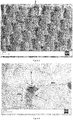
- Figures 1a-1c show SEM (Scanning Electron Microscope) images of the hierarchical structure.
- Figure 1a is a tilted SEM image showing the micrometre-sized square pillars 1 homogeneously distributed along a matrix of lines and columns.
- the pillars are identical and present a height H m of 40 ⁇ m and a width W m of 40 ⁇ m.
- the pillars are separated one from the others by a pitch D m (distance centre to centre) of 115 ⁇ m.
- Figure 1b is a magnified tilted SEM view of one pillar of Figure 1a : it illustrates nanometre-sized pillars 2 positioned at the upper surface of the micrometre-sized pillars 1. These nanometre-sized pillars are homogeneously distributed along a matrix of lines and columns. Next lines are offset one to the other. The pillars are identical.
- Figure 1c is a magnified photo of several nano-sized pillars of Figure 1b : the nano-sized pillars 2 present a round section with a height h n of 750 nm.
- the pillars are slightly conical, the round shape at the base stretching at the top of the pillars.
- the width w n at the base is of 500 nm.
- the pillars are separated one from the others at the base by a maximal pitch d n of 750 nm.
- the photo of Figure 1c shows the upper surface of the nano-sized pillars.
- the upper surface comprises nanometre-sized protrusions 3 : these nanometre-sized protrusions present irregular heights, yet these heights remain comprised between 100 and 400 nm.
- the density of these nanometre-sized protrusions at the upper surface of the pillars is of about 10 7 protrusions/mm 2 . These protrusions are positioned in a non-periodic, irregular pattern.
- Figure 2 is a photo showing a second micro- and nano-meter hierarchical patterned structure used as a hydrophobic liquid contact surface portion in the components of beverage dispensers according to the invention.
- Figure 2 is a magnified tilted SEM view of cylindrical micrometre-sized pillars 1 with cylindrical nano-sized pillars 2 rising from their top surface. These micrometre-sized pillars 1 are homogeneously distributed along a matrix of lines and columns. Next lines are offset one to the other. The pillars are identical.
- the nanometre-sized protrusions at the top of the nano-sized pillars 2 are not visible in the photo at this magnification, yet they are present. These nanometre-sized protrusions present the same features as those present in the structure of Figure 1c .
- the micrometre-sized cylindrical pillars 1 are homogeneously distributed along a matrix of lines and columns.
- the pillars 1 are identical and present a height H m of 20 ⁇ m and a width W m of 5 ⁇ m.
- the pillars are separated one from the others by a pitch D m (distance centre to centre) of 15 ⁇ m.
- the nanometre-sized cylindrical pillars 2 are homogeneously distributed along a matrix of lines and columns.
- the pillars 2 are identical and present a height h n of 750 nm and a width w m of 500 nm.
- the pillars are separated one from the others by a pitch d n (distance centre to centre) of 750 nm.
- Figure 3 is a photo showing a third micro- and nano-meter hierarchical patterned structure used as a hydrophobic liquid contact surface portion in the components of beverage dispensers according to the invention.
- Figure 3 is a magnified tilted SEM view of cylindrical micrometre-sized pillars 1 with slightly visible cylindrical nano-sized pillars 2 rising from their top surface. These micrometre-sized pillars 1 are homogeneously distributed along a matrix of lines and columns. Next lines are offset one to the other. The pillars are identical.
- the nanometre-sized protrusions at the top of the nano-sized pillars 2 are not visible in the photo at this magnification, yet they are present. These nanometre-sized protrusions present the same features as those present in the structure of Figure 1c .
- the micrometre-sized cylindrical pillars 1 are homogeneously distributed along a matrix of lines and columns.
- the pillars 1 are identical and have been manufactured from an Ni stamp presenting a reverse design to produce pillars 1 presenting a height Hm of 30 ⁇ m and a width Wm of 5 ⁇ m. Yet, during the step of removing the propylene foil from the Ni stamp, pillars 1 were stretched resulting in pillars with a slightly higher final height. Pillars are separated one from the others by a pitch Dm (distance centre to centre) of 15 ⁇ m.
- the nanometre-sized cylindrical pillars 2 are homogeneously distributed along a matrix of lines and columns.
- the pillars 2 are identical and, similarly to pillars 1 have been stretched during the manufacturing step ; the Ni stamp was configured to produce pillars 2 of a height hn of 750 nm and a width wm of 500 nm.
- the pillars are separated one from the others by a pitch dn (distance centre to centre) of 750 nm.
- Figure 4 is a photo showing a micro- and nano-meter hierarchical patterned structure used as a hydrophobic liquid contact surface portion according to the state of the art.
- Figure 4 is a tilted SEM image showing the micrometre-sized round pillars 1 homogeneously distributed along a matrix of lines and columns in an hexagonal array. All the pillars are identical and present a height H m of 16 ⁇ m and a diameter W m of 18 ⁇ m. The pillars are separated one from the others by a pitch D m of 50 ⁇ m.
- Nanometre-sized protrusions 3 at the top of the micro-sized pillars 1 are not visible in the illustrated figure at this magnification, yet they are present. Nanometre-sized protrusions presenting a height comprised between 200 and 400 nm at a density of 10 7 protrusions/mm 2 were measured. These protrusions are positioned in a non-periodic, irregular pattern.
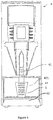
- FIG. 5 illustrates a beverage dispensing apparatus 4.
- This apparatus dispenses beverage from a dispensing nozzle 41 in a drinking container positioned on a cup holder 42 in a receiving area 47.
- drops of beverages may splash in this receiving area and on the cup holder. Beverage drops may also stay in in the dispensing nozzle 41.
- FIG. 6 illustrates a beverage preparation chamber 43 of the beverage dispensing apparatus 4.
- a dispensing nozzle 41 is attached to the outlet 431 of the chamber in order to dispense the beverage to the drinking container.
- This nozzle is difficult to clean on account of its small size. Yet it must be frequently cleaned since it is in contact with beverages which leave potential residues inside. It must be frequently replaced.
- a water supply tube 44 is provided at the top of the chamber. When hot water is supplied, scale deposit increased inside this tube requiring regular descaling. Scaling is increased by stagnation of hot water in the tube.
- Figure 7 illustrates mixing nozzles 45, 46 of a beverage dispensing apparatus. These nozzles provide hot water in a drinking cup comprising a soluble beverage ingredient. The nozzles can deliver a several jets of water or one flow of water. Whatever the form of the nozzle, the same issue of scaling exist as for the water supply tube 44 of Figure 6 .
- vertical walls 471 presenting hydrophobic liquid contact surface prevent drops of hot water and hot beverages from being pinned on : the drops flows down and are collected in the cup holder that is easily cleaned.
Landscapes
- Engineering & Computer Science (AREA)
- Manufacturing & Machinery (AREA)
- Mechanical Engineering (AREA)
- Food Science & Technology (AREA)
- Devices For Dispensing Beverages (AREA)
- Apparatus For Making Beverages (AREA)
- Detergent Compositions (AREA)
- Non-Alcoholic Beverages (AREA)
Abstract
- homogeneously distributed micrometre-sized pillars (1), and
- homogeneously distributed nanometre-sized pillars (2) at the upper surface of the micrometre-sized pillars, and
- nanometre-sized protrusions (3) at the upper surface of the nanometre-sized pillars, said protrusions being positioned in a non-periodic, irregular pattern.
Description
- The present invention relates to beverage dispensers, in particular dispensing hot beverages.
- Beverage dispensers are commonly used to dispense beverages like coffee, tea, chocolate, milk. The beverages can be simply stored in the dispenser and dispensed therefrom or in more complex machines, the beverage can be prepared inside the machine before being dispensed.
- Beverage dispensers must be regularly cleaned in order to avoid any hygiene issue and to provide an appealing aspect for consumers. Cleaning concerns internal parts of the dispenser and external parts of the dispenser as a part of dirtiness is due to the liquids circulating inside the dispenser and another part to liquids splashing outside the dispenser. The operation of cleaning beverage dispensers is time consuming and must be frequently repeated. During the cleaning, the dispenser cannot be operated and the presence of an operator is necessary.
- Different solutions have been proposed to facilitate cleaning operations. One consists in providing beverage dispensers with components presenting self-cleaning properties and/or water repellent property. Since beverages are usually essentially made of water, the water repellant property of beverage dispenser components in contact with liquids prevents liquids from adhering, stagnating and drying on the surfaces of the dispenser. Liquids flow easily without being retained and this source of dirtiness is reduced.
The water repellent or hydrophobic property of the components can be obtained through different technologies. Chemical coatings have been used but their use can be unhealthy. An interesting technology is nano-imprint lithography which consists in imprinting micro- and nanostructures on components surfaces.WO 2013/131525 describes such types of structures and a method to imprint them : surfaces of injection molded polymers with such structures present very good hydrophobic property, water drops rolling off these surfaces very easily.
It has been observed that these structures provide efficient hydrophobicity with water used at ambient or cold temperature, yet, if water is hot, the hydrophobicity property decreases, and if water is mixed with a fat component, such as milk or chocolate beverages do, the hydrophobicity decreases even more. As a result the self-cleaning advantage of these structures does not exist in machines dispensing hot beverages like coffee, tea, and even fat beverages like chocolate or milk. - There is a need for providing beverage dispenser components with surfaces presenting hydrophobic property whatever the temperature of the beverage in contact with the components, that is either cold, ambient or hot.
- In a first aspect of the invention, there is provided a component configured for handling a liquid and/or able to be contacted by a liquid for use in a beverage dispensing apparatus, said component comprising at least one hydrophobic liquid contact surface portion, wherein said hydrophobic liquid contact surface portion presents a micro- and nano-meter hierarchical patterned structure, said structure comprising :
- homogeneously distributed micrometre-sized pillars, and
- homogeneously distributed nanometre-sized pillars at the upper surface of the micrometre-sized pillars, and
- nanometre-sized protrusions at the upper surface of the nanometre-sized pillars, said protrusions being positioned in a non-periodic, irregular pattern.
- The beverage dispensing apparatus can be configured for storing a ready to drink beverage and dispense one single dose of this beverage.
Alternatively the beverage dispensing apparatus can be configured to prepare one single dose of beverage and to dispense it. The apparatus is not limited in term of type of beverage preparation.
The apparatus can prepare the beverage from beverage ingredient and can comprise a storing container for the ingredient and a dosing device of the ingredient. In one embodiment, this apparatus can comprise a chamber to mix a dose of ingredient with water before dispensing the resulting beverage. In another embodiment, this apparatus can comprise a mixing nozzle to introduce a jet of water in a cup containing a dose of ingredient. The apparatus can prepare the beverage from a single dose capsule comprising a beverage ingredient.
The apparatus can prepare a foamed beverage from a flat beverage, such as milk and can comprise a foaming device. - The component configured for handling a liquid can be a water tank and the hydrophobic liquid contact surface portion can be positioned at least on a lateral side wall of the tank.
- Consequently, any water drop at the lateral side wall, either internal or external wall, easily falls down from the wall. Traces due to dried water drops are avoided.
The component configured for handling a liquid can be a tube configured for dispensing water or beverage and at least a part of the internal surface of the tube presents a hydrophobic liquid contact surface. Any tube dispensing water from the water supply or dispensing beverage from a beverage mixing chamber, a brewing chamber or a capsule can be concerned. The tube can be a nozzle.
The component able to be contacted by a liquid can be an area configured for holding a drinking container. During dispensing of the beverage in the drinking container, drops of beverage can splash and fall on the surfaces of this cup holding area. - Whatever the function of the component, said component comprises at least one hydrophobic liquid contact surface portion.
Preferably, this portion with hydrophobic property corresponds to the part of the component in contact with liquid during the beverage preparation and/or dispensing. - The hydrophobic property is provided by the design of the surface of said liquid contact surface portion. Precisely, this surface presents a micro- and nano-meter hierarchical patterned structure with three levels of patterns.
- According to preferred embodiments, the micro- and nano-meter hierarchical patterned structure comprises :
- homogeneously distributed micrometre-sized pillars presenting a height of at least 3 µm, preferably comprised between 5 and 50 µm,
- homogeneously distributed nanometre-sized pillars at the upper surface of the micrometre-sized pillars presenting a height comprised between 500 nm and 1000 nm, preferably comprised between 600 and 800 nm, and
- nanometre-sized protrusions at the upper surface of the nanometre-sized pillars presenting a height comprised between 50 and 400 nm.
- The first level of the structure comprises micrometre-sized pillars.
These micrometre-sized pillars present a shape and an supper surface configured to define a support for the homogeneously distributed nanometre-sized pillars.
These micrometre-sized pillars usually present a relatively homogeneous cross section all along their height and the cross section can present any shape (round, oval, square, rectangular, hexagonal). Alternatively, the cross section of the pillars can vary along the height. For example the pillars can present the shape of half spheres, the cross section of the pillar decreasing from the base to the top.
Preferably the micrometre-sized pillars are parallelepipedic or round pillars.
These pillars are homogeneously distributed. Preferably they are homogeneously distributed along lines, two next lines being either aligned (array distribution) or offset (hexagonal distribution). Preferably the lines are aligned (array distribution).
These micrometre-sized pillars can present a width comprised between 3 and 70 µm, preferably between 10 and 60 µm. The width represents the length of the side in case of a square shape or the diameter in case of a cylindrical shape. Preferably, the width represents 1/3 to 1 time the height.
These micrometre-sized pillars can be separated one from the others by a pitch of at most 8 times the width of said pillar. The pitch is the distance from the centre of one pillar to the centre of the next pillar. - The second level of the structure comprises homogeneously distributed nanometre-sized pillars present at the upper surface of the micrometre-sized pillars.
These nanometre-sized pillars present a shape and an supper surface configured to define a support for the nanometre-sized protrusions.
These nanometre-sized pillars usually present a relatively homogeneous cross section all along their height and the cross section can present any shape (round, oval, square, rectangular, hexagonal). Alternatively, the cross section of the pillars can vary along the height. For example the pillars can present the shape of half spheres, the cross section of the pillar decreasing from the base to the top.
Preferably the nanometre-sized pillars are round pillars.
These pillars are homogeneously distributed. Preferably they are homogeneously distributed along lines, two next lines being either aligned (array distribution) or offset (hexagonal distribution). Preferably the lines are aligned (array distribution).
These nanometre-sized pillars can present a width comprised between 400 and 1000 nm, preferably between 400 and 700 nm. Preferably, the width represents 1/5 to 1 time the height.
These nanometre-sized pillars can be separated one from the others by a pitch of at most 6 times the width of said pillar. The pitch is the distance from the centre of one pillar to the centre of the next pillar. - The third level of the structure comprises nanometre-sized protrusions at the upper surface of the nanometre-sized pillars. Contrary to the nanometre-sized pillars, the protrusions do not present well defined shapes. These protrusions are positioned in a non-periodic, irregular pattern at the upper surface of the nanometre-sized pillars.
These nanometre-sized protrusions present heights comprised between 10 and 400 nm and said height is inferior to the height of the nanometre-sized pillars on which upper surface they protrude. The nanometre-sized protrusions present a minimum density of 105 protrusions/mm2, preferably within an interval of 105 to 108 protrusions/mm2.
Typically, the nanometer-sized protrusions may have an aspect ratio (A), i.e. height / width of structure on average, ofminimum maximum
It is to be understood that the density is calculated on an average basis as will be appreciated by a person working with micro-technologies. The concept of a non-period, irregular pattern is to be understood by the skilled person as seen on or viewed on a nanometer scale, e.g. using scanning electron microscopy (SEM) or an atomic force microscopy (AFM). Using for example a pixel size of approximately 2-20 nm in SEM, the master structure will be shown to have a protrusion distribution with such a pattern. - Preferably the component configured for handling a liquid and/or able to be contacted by a liquid is made of a plastic polymer and is produced by injection molding and the micro- and nano-meter hierarchical patterned structure is imprinted at the surface of the component during the injection molding operation.
- Generally the plastic polymer the component is made of is a plastic polymer not charged with fibres. Actually, the presence of fibres does not enable the molding of the patterned surface as desired. The polymer is preferably polypropylene or polyamide.
- In one embodiment, the component can be a water tank and at least one internal lateral side wall of the tank presents at least one hydrophobic liquid contact surface portion such as described above.
- In another embodiment, the component can be a tube and at least a part of the internal surface of the tube presents a hydrophobic liquid contact surface such as described above.
This tube can be configured for dispensing water, milk or any ready-to drink or just prepared beverage.
This tube can be a nozzle or needle.
This tube can be configured for dispensing a beverage prepared in an upstream mixing chamber or in an upstream beverage capsule. - This tube can be a mixing nozzle configured to receive and mix together a diluent and at least one concentrate before dispensing the mixture in a cup.
This tube can be a connector between different devices of a beverage apparatus such as liquid tank, pump, mixing chamber, capsule holder, cup holder, drip tray. - In another embodiment, the component can be a cup holder and at least a part of the external surface of the cup holder presents at least one hydrophobic liquid contact surface portion such as described above.
- In a second aspect, there is provided a beverage dispensing apparatus comprising at least one component such as described above.
- In a third aspect, there is provided a use of a hydrophobic liquid contact surface portion presenting a micro- and nano-meter hierarchical patterned structure in at least one component for handling a liquid and/or able to be contacted by a liquid of a beverage dispensing apparatus, said structure comprising :
- homogeneously distributed micrometre-sized pillars, and
- homogeneously distributed nanometre-sized pillars at the upper surface of the micrometre-sized pillars, and
- nanometre-sized protrusions at the upper surface of the nanometre-sized pillars, said protrusions being positioned in a non-periodic, irregular pattern.
- Preferably, the micro- and nano-meter hierarchical patterned structure comprises :
- homogeneously distributed micrometre-sized pillars presenting a height of at least 3 µm, preferably comprised between 5 and 50 µm,
- homogeneously distributed nanometre-sized pillars at the upper surface of the micrometre-sized pillars presenting a height comprised between 500 nm and 1000 nm, preferably comprised between 600 and 800 nm, and
- nanometre-sized protrusions at the upper surface of the nanometre-sized pillars presenting a height comprised between 50 and 400 nm.
- The hydrophobic liquid contact surface portion is used in at least one component for handling a hot liquid and/or able to be contacted by a hot liquid for use in a beverage dispensing apparatus.
The hot liquid can be hot water, coffee, tea chocolate, milk. - According to a fourth aspect, there is provided a plastic injection mold of a component such as described above comprising a patterned surface for moulding the hydrophobic liquid contact surface portion presenting the micro- and nano-meter hierarchical patterned structure.
- The above aspects of the invention may be combined in any suitable combination. Moreover, various features herein may be combined with one or more of the above aspects to provide combinations other than those specifically illustrated and described. Further objects and advantageous features of the invention will be apparent from the claims, from the detailed description, and annexed drawings.
- The characteristics and advantages of the invention will be better understood in relation to the following figures wherein :
-
Figures 1a-1c illustrates a first micro- and nano-meter hierarchical patterned structure used as a hydrophobic liquid contact surface portion according to the invention, -
Figure 2 illustrates a second micro- and nano-meter hierarchical patterned structure used as a hydrophobic liquid contact surface portion according to the invention, -
Figure 3 illustrates a third micro- and nano-meter hierarchical patterned structure used as a hydrophobic liquid contact surface portion according to the invention, -
Figure 4 illustrates a micro- and nano-meter hierarchical patterned structure used as a hydrophobic liquid contact surface portion according to the state of the art, -
Figure 5 illustrates a beverage dispensing apparatus comprising components configured for handling a liquid and/or able to be contacted by a liquid, -
Figure 6 illustrates a preparation chamber that can be used in the apparatus ofFigure 5 , -
Figure 7 illustrates water nozzles that can be used in the apparatus ofFigure 5 . -
Figures 1a-1c illustrate a first micro- and nano-meter hierarchical patterned structure used as a hydrophobic liquid contact surface portion in the components of beverage dispensing apparatuses according to the invention. In order to test the property of the structure, said structure was manufactured in polypropylene foil. Ni stamps presenting the reverse design were used for embossing the structure in the plastic foil. The process for manufacturing the Ni stamps and embossing polypropylene plastic is known and described inWO 2013/131525 .
Figures 1a-1c show SEM (Scanning Electron Microscope) images of the hierarchical structure. In these images, the view are tilted meaning that, depending on the angle taken for the view, the pillars and protrusions can appear slightly larger than in the reality or of smaller height than in the reality.
Figure 1a is a tilted SEM image showing the micrometre-sizedsquare pillars 1 homogeneously distributed along a matrix of lines and columns. The pillars are identical and present a height Hm of 40 µm and a width Wm of 40 µm. The pillars are separated one from the others by a pitch Dm (distance centre to centre) of 115 µm.
Figure 1b is a magnified tilted SEM view of one pillar ofFigure 1a : it illustrates nanometre-sized pillars 2 positioned at the upper surface of the micrometre-sized pillars 1. These nanometre-sized pillars are homogeneously distributed along a matrix of lines and columns. Next lines are offset one to the other. The pillars are identical.
Figure 1c is a magnified photo of several nano-sized pillars ofFigure 1b : the nano-sized pillars 2 present a round section with a height hn of 750 nm. The pillars are slightly conical, the round shape at the base stretching at the top of the pillars. The width wn at the base is of 500 nm. The pillars are separated one from the others at the base by a maximal pitch dn of 750 nm.
The photo ofFigure 1c shows the upper surface of the nano-sized pillars. The upper surface comprises nanometre-sized protrusions 3 : these nanometre-sized protrusions present irregular heights, yet these heights remain comprised between 100 and 400 nm. The density of these nanometre-sized protrusions at the upper surface of the pillars is of about 107 protrusions/mm2. These protrusions are positioned in a non-periodic, irregular pattern. -
Figure 2 is a photo showing a second micro- and nano-meter hierarchical patterned structure used as a hydrophobic liquid contact surface portion in the components of beverage dispensers according to the invention.
Figure 2 is a magnified tilted SEM view of cylindrical micrometre-sized pillars 1 with cylindrical nano-sized pillars 2 rising from their top surface. These micrometre-sized pillars 1 are homogeneously distributed along a matrix of lines and columns. Next lines are offset one to the other. The pillars are identical. The nanometre-sized protrusions at the top of the nano-sized pillars 2 are not visible in the photo at this magnification, yet they are present. These nanometre-sized protrusions present the same features as those present in the structure ofFigure 1c .
The micrometre-sizedcylindrical pillars 1 are homogeneously distributed along a matrix of lines and columns. Thepillars 1 are identical and present a height Hm of 20 µm and a width Wm of 5 µm. The pillars are separated one from the others by a pitch Dm (distance centre to centre) of 15 µm. - The nanometre-sized
cylindrical pillars 2 are homogeneously distributed along a matrix of lines and columns. Thepillars 2 are identical and present a height hn of 750 nm and a width wm of 500 nm. The pillars are separated one from the others by a pitch dn (distance centre to centre) of 750 nm. -
Figure 3 is a photo showing a third micro- and nano-meter hierarchical patterned structure used as a hydrophobic liquid contact surface portion in the components of beverage dispensers according to the invention.
Figure 3 is a magnified tilted SEM view of cylindrical micrometre-sized pillars 1 with slightly visible cylindrical nano-sized pillars 2 rising from their top surface. These micrometre-sized pillars 1 are homogeneously distributed along a matrix of lines and columns. Next lines are offset one to the other. The pillars are identical. The nanometre-sized protrusions at the top of the nano-sized pillars 2 are not visible in the photo at this magnification, yet they are present. These nanometre-sized protrusions present the same features as those present in the structure ofFigure 1c .
The micrometre-sizedcylindrical pillars 1 are homogeneously distributed along a matrix of lines and columns. Thepillars 1 are identical and have been manufactured from an Ni stamp presenting a reverse design to producepillars 1 presenting a height Hm of 30 µm and a width Wm of 5 µm. Yet, during the step of removing the propylene foil from the Ni stamp,pillars 1 were stretched resulting in pillars with a slightly higher final height. Pillars are separated one from the others by a pitch Dm (distance centre to centre) of 15 µm.
The nanometre-sizedcylindrical pillars 2 are homogeneously distributed along a matrix of lines and columns. Thepillars 2 are identical and, similarly topillars 1 have been stretched during the manufacturing step ; the Ni stamp was configured to producepillars 2 of a height hn of 750 nm and a width wm of 500 nm. The pillars are separated one from the others by a pitch dn (distance centre to centre) of 750 nm. -
Figure 4 is a photo showing a micro- and nano-meter hierarchical patterned structure used as a hydrophobic liquid contact surface portion according to the state of the art.
Figure 4 is a tilted SEM image showing the micrometre-sized round pillars 1 homogeneously distributed along a matrix of lines and columns in an hexagonal array. All the pillars are identical and present a height Hm of 16 µm and a diameter Wm of 18 µm. The pillars are separated one from the others by a pitch Dm of 50 µm.
Nanometre-sized protrusions 3 at the top of themicro-sized pillars 1 are not visible in the illustrated figure at this magnification, yet they are present. Nanometre-sized protrusions presenting a height comprised between 200 and 400 nm at a density of 107 protrusions/mm2 were measured. These protrusions are positioned in a non-periodic, irregular pattern. - The hydrophobic properties of the foils of plastic describes in
Figures 1a-1c ,2 ,3 and 4 were tested with hot beverages.
The procedure of the test consisted in : - cleaning the foil with ethanol and then deionized water,
- positioning the foil according to an inclined angle of 5° or 45° with horizontal, that is reproducing a very small inclination inside a component of a beverage dispenser,
- depositing manually a drop (volume of 50 µl) of hot beverage on the foil. The hot beverage presented a temperature of 70 °C and consisted in water, coffee, skimmed milk, fat milk or chocolate,
- observing the movement of the drop on the surface of the foil.
-
Figure 5 illustrates abeverage dispensing apparatus 4. This apparatus dispenses beverage from a dispensingnozzle 41 in a drinking container positioned on acup holder 42 in a receivingarea 47. During beverage dispensing, drops of beverages may splash in this receiving area and on the cup holder. Beverage drops may also stay in in the dispensingnozzle 41. -
Figure 6 illustrates abeverage preparation chamber 43 of thebeverage dispensing apparatus 4. A dispensingnozzle 41 is attached to theoutlet 431 of the chamber in order to dispense the beverage to the drinking container. This nozzle is difficult to clean on account of its small size. Yet it must be frequently cleaned since it is in contact with beverages which leave potential residues inside. It must be frequently replaced.
At the top of the chamber, awater supply tube 44 is provided. When hot water is supplied, scale deposit increased inside this tube requiring regular descaling. Scaling is increased by stagnation of hot water in the tube. -
Figure 7 illustrates mixingnozzles water supply tube 44 ofFigure 6 . - By providing hydrophobic liquid contact surface portion inside the different illustrated components, hot water and hot beverages are prevented from stagnating on the surface of the components and limit dirtiness and scaling. Theses liquids do not dry inside the components, they totally flow in the drinking container.
- In the receiving area,
vertical walls 471 presenting hydrophobic liquid contact surface prevent drops of hot water and hot beverages from being pinned on : the drops flows down and are collected in the cup holder that is easily cleaned. - The same principle applies in the water tank and its internal vertical walls 481.
- Although the invention has been described with reference to the above illustrated embodiments, it will be appreciated that the invention as claimed is not limited in any way by these illustrated embodiments.
Variations and modifications may be made without departing from the scope of the invention as defined in the claims. Furthermore, where known equivalents exist to specific features, such equivalents are incorporated as if specifically referred in this specification.
As used in this specification, the words "comprises", "comprising", and similar words, are not to be interpreted in an exclusive or exhaustive sense. In other words, they are intended to mean "including, but not limited to".List of references in the drawings : micro-sized pillar 1 nano- sized pillar 2 nanometre- sized protrusion 3 beverage dispensing apparatus 4 dispensing nozzle 41 cup holder 42 beverage preparation chamber 43 outlet 431 water supply tube 44 mixing nozzle 45, 46 receiving area 47 vertical wall 471 water tank 48 vertical wall 471 drinking cup 5
| Type of patterned structure | Result of the test |
| According to the invention | |
| micro + nano + nano-meter hierarchical patterned structure of | - drops of hot water rolled immediately from the foil inclined at 5°, |
| - drops of hot skimmed milk and fat milk rolled immediately from the foil if the foil was inclined by 45°. | |
| - drops of coffee and chocolate did not roll off even inclined at 45°. | |
| micro + nano + nano-meter hierarchical patterned structures of | - drops of hot water rolled immediately from the foil inclined at 5°, |
| - drops of hot skimmed milk, fat milk, coffee and chocolate rolled immediately from the foil if the foil was inclined by 45°. | |
| According to the prior art | |
| micro + nano-meter hierarchical patterned structure of | - drops of hot water rolled immediately from the foil inclined at 5°, |
| - drops of hot beverages did not roll off from the foil inclined by 45°. | |
Claims (16)
- A component (41, 42, 43, 15, 46, 47, 48) configured for handling a liquid and/or able to be contacted by a liquid for use in a beverage dispensing apparatus, said component comprising at least one hydrophobic liquid contact surface portion, wherein said hydrophobic liquid contact surface portion presents a micro- and nano-meter hierarchical patterned structure, said structure comprising :- homogeneously distributed micrometre-sized pillars (1), and- homogeneously distributed nanometre-sized pillars (2) at the upper surface of the micrometre-sized pillars, and- nanometre-sized protrusions (3) at the upper surface of the nanometre-sized pillars, said protrusions being positioned in a non-periodic, irregular pattern.
- A component according to Claim 1, wherein the micro- and nano-meter hierarchical patterned structure comprises :- homogeneously distributed micrometre-sized pillars (1) presenting a height of at least 3 µm, preferably comprised between 5 and 50 µm,- homogeneously distributed nanometre-sized pillars (2) at the upper surface of the micrometre-sized pillars presenting a height comprised between 500 nm and 1000 nm, preferably comprised between 600 and 800 nm, and- nanometre-sized protrusions (3) at the upper surface of the nanometre-sized pillars presenting a height comprised between 50 and 400 nm.
- A component according to Claim 1 or 2, wherein the micrometre-sized pillars (1) of the micro- and nano-meter hierarchical patterned structure present a width comprised between 3 and 70 µm, preferably between 10 and 60 µm.
- A component according to any one of the precedent claims, the micrometre-sized pillars (1) of the micro- and nano-meter hierarchical patterned structure are separated one from the others by a pitch of at most 8 times the width of said pillars (1).
- A component according to any one of the precedent claims, wherein the nanometre-sized pillars (2) of the micro- and nano-meter hierarchical patterned structure present a width comprised between 400 and 1000 nm, preferably between 400 and 700 nm.
- A beverage dispensing apparatus (4) according to any one of the precedent claims, the nanometre-sized pillars (2) of the micro- and nano-meter hierarchical patterned structure are separated one from the others by a pitch of at most 6 times the width of said pillars (2).
- A component according to any one of the precedent claims, wherein the micrometre-sized pillars (1) are parallelepipedic or round.
- A component according to any one of the precedent claims, wherein the nanometre-sized pillars (2) are round or truncated cones
- A component according to any one of the precedent claims, wherein the component is made of a plastic polymer and is produced by injection molding and the micro- and nano-meter hierarchical patterned structure is imprinted at the surface of the component during the injection molding operation.
- A component according to any one of the precedent claims, wherein said component is a water tank and at least one internal lateral side wall of the tank presents at least one hydrophobic liquid contact surface portion.
- A component according to any one of Claims 1 to 9, wherein said component is a tube (41, 431, 44, 45, 46) and at least a part of the internal surface of the tube presents a hydrophobic liquid contact surface.
- A component according to any one of Claims 1 to 9, wherein said component is a cup holder (42) and at least a part of the external surface of the cup holder presents at least one hydrophobic liquid contact surface portion.
- A beverage dispensing apparatus (4) comprising at least one component (41, 42, 43, 44, 45, 46, 47) according to any one of Claims 1 to 12.
- Use of a hydrophobic liquid contact surface portion presenting a micro- and nano-meter hierarchical patterned structure in at least one component for handling a liquid and/or able to be contacted by a liquid of a beverage dispensing apparatus, said structure comprising :- homogeneously distributed micrometre-sized pillars (1), and- homogeneously distributed nanometre-sized pillars (2) at the upper surface of the micrometre-sized pillars, and- nanometre-sized protrusions (3) at the upper surface of the nanometre-sized pillars, said protrusions being positioned in a non-periodic, irregular pattern.
- Use according to the precedent claim, wherein the micro- and nano-meter hierarchical patterned structure comprises :- homogeneously distributed micrometre-sized pillars (1) presenting a height of at least 3 µm, preferably comprised between 5 and 50 µm,- homogeneously distributed nanometre-sized pillars (2) at the upper surface of the micrometre-sized pillars presenting a height comprised between 500 nm and 1000 nm, preferably comprised between 600 and 800 nm, and- nanometre-sized protrusions (3) at the upper surface of the nanometre-sized pillars presenting a height comprised between 50 and 400 nm.
- Plastic injection mold of a component according to any one of Claims 1 to 12 comprising a patterned surface for moulding the hydrophobic liquid contact surface portion presenting the micro- and nano-meter hierarchical patterned structure.
Priority Applications (2)
| Application Number | Priority Date | Filing Date | Title |
|---|---|---|---|
| EP19153510.3A EP3685715B1 (en) | 2019-01-24 | 2019-01-24 | Beverage dispenser with self-cleaning components |
| ES19153510T ES2939117T3 (en) | 2019-01-24 | 2019-01-24 | Beverage dispenser with self-cleaning components |
Applications Claiming Priority (1)
| Application Number | Priority Date | Filing Date | Title |
|---|---|---|---|
| EP19153510.3A EP3685715B1 (en) | 2019-01-24 | 2019-01-24 | Beverage dispenser with self-cleaning components |
Publications (2)
| Publication Number | Publication Date |
|---|---|
| EP3685715A1 true EP3685715A1 (en) | 2020-07-29 |
| EP3685715B1 EP3685715B1 (en) | 2022-11-30 |
Family
ID=65228461
Family Applications (1)
| Application Number | Title | Priority Date | Filing Date |
|---|---|---|---|
| EP19153510.3A Active EP3685715B1 (en) | 2019-01-24 | 2019-01-24 | Beverage dispenser with self-cleaning components |
Country Status (2)
| Country | Link |
|---|---|
| EP (1) | EP3685715B1 (en) |
| ES (1) | ES2939117T3 (en) |
Citations (5)
| Publication number | Priority date | Publication date | Assignee | Title |
|---|---|---|---|---|
| WO2009028745A1 (en) * | 2007-08-28 | 2009-03-05 | Lg Electronics Inc. | Injection moldings, injection-molding apparatus and method thereof |
| WO2012048870A2 (en) * | 2010-10-13 | 2012-04-19 | Max-Planck-Gesellschaft Zur Foerderung Der Wissenschaften E.V | Process for producing highly ordered nanopillar or nanohole structures on large areas |
| WO2012061753A2 (en) * | 2010-11-05 | 2012-05-10 | Molecular Imprints, Inc. | Nanoimprint lithography formation of functional nanoparticles using dual release layers |
| WO2013131525A1 (en) | 2012-03-09 | 2013-09-12 | Danmarks Tekniske Universitet | A method for manufacturing a tool part for an injection molding process, a hot embossing process, a nano-imprint process, or an extrusion process |
| US20130330501A1 (en) * | 2010-07-19 | 2013-12-12 | Joanna Aizenberg | Hierarchical structured surfaces to control wetting characteristics |
-
2019
- 2019-01-24 ES ES19153510T patent/ES2939117T3/en active Active
- 2019-01-24 EP EP19153510.3A patent/EP3685715B1/en active Active
Patent Citations (5)
| Publication number | Priority date | Publication date | Assignee | Title |
|---|---|---|---|---|
| WO2009028745A1 (en) * | 2007-08-28 | 2009-03-05 | Lg Electronics Inc. | Injection moldings, injection-molding apparatus and method thereof |
| US20130330501A1 (en) * | 2010-07-19 | 2013-12-12 | Joanna Aizenberg | Hierarchical structured surfaces to control wetting characteristics |
| WO2012048870A2 (en) * | 2010-10-13 | 2012-04-19 | Max-Planck-Gesellschaft Zur Foerderung Der Wissenschaften E.V | Process for producing highly ordered nanopillar or nanohole structures on large areas |
| WO2012061753A2 (en) * | 2010-11-05 | 2012-05-10 | Molecular Imprints, Inc. | Nanoimprint lithography formation of functional nanoparticles using dual release layers |
| WO2013131525A1 (en) | 2012-03-09 | 2013-09-12 | Danmarks Tekniske Universitet | A method for manufacturing a tool part for an injection molding process, a hot embossing process, a nano-imprint process, or an extrusion process |
Also Published As
| Publication number | Publication date |
|---|---|
| EP3685715B1 (en) | 2022-11-30 |
| ES2939117T3 (en) | 2023-04-19 |
Similar Documents
| Publication | Publication Date | Title |
|---|---|---|
| CN105408031B (en) | Liquid-impregnated surface for enhanced durability | |
| JP2022008293A (en) | Equipment and processes for distributing measured quantities of liquid products | |
| US9801506B2 (en) | Wet/dry sheet dispenser with dispensing cup | |
| CN103517754B (en) | Method and device for homogenizing liquid | |
| DE69030380T2 (en) | DEVICE FOR PRODUCING OR DISTRIBUTING BEVERAGES | |
| DE20020254U1 (en) | Resealable fastener for connecting a container to a distribution device | |
| EP3685715B1 (en) | Beverage dispenser with self-cleaning components | |
| CN110418676A (en) | For generating the device and method of microfoam | |
| WO2017179684A1 (en) | Foam discharge device | |
| CN105307544A (en) | Mixing chamber for producing beverages | |
| JP2017193374A (en) | Foam discharge device | |
| DE29924728U1 (en) | Spray container for plant watering has water container with dispensing head having fill opening for water | |
| TWI736609B (en) | Foam spray device | |
| EP0953312A1 (en) | Dispensing unit | |
| US6155413A (en) | Carpet refurbishing kit | |
| DE102013013556B4 (en) | Holding device for a hand-operated foamer | |
| JP6622246B2 (en) | Foam discharge device | |
| JP7744117B2 (en) | Foam dispenser and foam container | |
| DE602005003120T2 (en) | APPARATUS FOR PRODUCING AT LEAST ONE DRINK BEAM AND BEVERAGE APPARATUS WITH SUCH A DEVICE | |
| DE10103269A1 (en) | Glass washing machine for bars and cafes, uses clean water reservoir to supply internal brush assembly and external jets with controlled flow to replace water in main sink | |
| KR101622367B1 (en) | Injection module for uniform distribution | |
| AT15778U1 (en) | Auxiliary for the preparation of layered cocktails | |
| AU2004284019B2 (en) | A dispensing unit for controlled discharge of metered volume | |
| EP3463676B1 (en) | Foam dispenser | |
| DE102019122556A1 (en) | Decoration module for decorating a surface of a beverage |
Legal Events
| Date | Code | Title | Description |
|---|---|---|---|
| PUAI | Public reference made under article 153(3) epc to a published international application that has entered the european phase |
Free format text: ORIGINAL CODE: 0009012 |
|
| STAA | Information on the status of an ep patent application or granted ep patent |
Free format text: STATUS: THE APPLICATION HAS BEEN PUBLISHED |
|
| AK | Designated contracting states |
Kind code of ref document: A1 Designated state(s): AL AT BE BG CH CY CZ DE DK EE ES FI FR GB GR HR HU IE IS IT LI LT LU LV MC MK MT NL NO PL PT RO RS SE SI SK SM TR |
|
| AX | Request for extension of the european patent |
Extension state: BA ME |
|
| STAA | Information on the status of an ep patent application or granted ep patent |
Free format text: STATUS: REQUEST FOR EXAMINATION WAS MADE |
|
| 17P | Request for examination filed |
Effective date: 20210129 |
|
| RBV | Designated contracting states (corrected) |
Designated state(s): AL AT BE BG CH CY CZ DE DK EE ES FI FR GB GR HR HU IE IS IT LI LT LU LV MC MK MT NL NO PL PT RO RS SE SI SK SM TR |
|
| RIC1 | Information provided on ipc code assigned before grant |
Ipc: B08B 17/06 20060101ALI20220524BHEP Ipc: B29C 33/42 20060101ALI20220524BHEP Ipc: B29C 45/37 20060101ALI20220524BHEP Ipc: A47J 31/44 20060101AFI20220524BHEP |
|
| GRAP | Despatch of communication of intention to grant a patent |
Free format text: ORIGINAL CODE: EPIDOSNIGR1 |
|
| STAA | Information on the status of an ep patent application or granted ep patent |
Free format text: STATUS: GRANT OF PATENT IS INTENDED |
|
| INTG | Intention to grant announced |
Effective date: 20220707 |
|
| GRAS | Grant fee paid |
Free format text: ORIGINAL CODE: EPIDOSNIGR3 |
|
| GRAA | (expected) grant |
Free format text: ORIGINAL CODE: 0009210 |
|
| STAA | Information on the status of an ep patent application or granted ep patent |
Free format text: STATUS: THE PATENT HAS BEEN GRANTED |
|
| AK | Designated contracting states |
Kind code of ref document: B1 Designated state(s): AL AT BE BG CH CY CZ DE DK EE ES FI FR GB GR HR HU IE IS IT LI LT LU LV MC MK MT NL NO PL PT RO RS SE SI SK SM TR |
|
| REG | Reference to a national code |
Ref country code: CH Ref legal event code: EP Ref country code: GB Ref legal event code: FG4D |
|
| REG | Reference to a national code |
Ref country code: AT Ref legal event code: REF Ref document number: 1533995 Country of ref document: AT Kind code of ref document: T Effective date: 20221215 Ref country code: DE Ref legal event code: R096 Ref document number: 602019022399 Country of ref document: DE |
|
| REG | Reference to a national code |
Ref country code: IE Ref legal event code: FG4D |
|
| REG | Reference to a national code |
Ref country code: NL Ref legal event code: FP |
|
| REG | Reference to a national code |
Ref country code: LT Ref legal event code: MG9D |
|
| REG | Reference to a national code |
Ref country code: ES Ref legal event code: FG2A Ref document number: 2939117 Country of ref document: ES Kind code of ref document: T3 Effective date: 20230419 |
|
| PG25 | Lapsed in a contracting state [announced via postgrant information from national office to epo] |
Ref country code: SE Free format text: LAPSE BECAUSE OF FAILURE TO SUBMIT A TRANSLATION OF THE DESCRIPTION OR TO PAY THE FEE WITHIN THE PRESCRIBED TIME-LIMIT Effective date: 20221130 Ref country code: PT Free format text: LAPSE BECAUSE OF FAILURE TO SUBMIT A TRANSLATION OF THE DESCRIPTION OR TO PAY THE FEE WITHIN THE PRESCRIBED TIME-LIMIT Effective date: 20230331 Ref country code: NO Free format text: LAPSE BECAUSE OF FAILURE TO SUBMIT A TRANSLATION OF THE DESCRIPTION OR TO PAY THE FEE WITHIN THE PRESCRIBED TIME-LIMIT Effective date: 20230228 Ref country code: LT Free format text: LAPSE BECAUSE OF FAILURE TO SUBMIT A TRANSLATION OF THE DESCRIPTION OR TO PAY THE FEE WITHIN THE PRESCRIBED TIME-LIMIT Effective date: 20221130 Ref country code: FI Free format text: LAPSE BECAUSE OF FAILURE TO SUBMIT A TRANSLATION OF THE DESCRIPTION OR TO PAY THE FEE WITHIN THE PRESCRIBED TIME-LIMIT Effective date: 20221130 |
|
| REG | Reference to a national code |
Ref country code: AT Ref legal event code: MK05 Ref document number: 1533995 Country of ref document: AT Kind code of ref document: T Effective date: 20221130 |
|
| PG25 | Lapsed in a contracting state [announced via postgrant information from national office to epo] |
Ref country code: RS Free format text: LAPSE BECAUSE OF FAILURE TO SUBMIT A TRANSLATION OF THE DESCRIPTION OR TO PAY THE FEE WITHIN THE PRESCRIBED TIME-LIMIT Effective date: 20221130 Ref country code: PL Free format text: LAPSE BECAUSE OF FAILURE TO SUBMIT A TRANSLATION OF THE DESCRIPTION OR TO PAY THE FEE WITHIN THE PRESCRIBED TIME-LIMIT Effective date: 20221130 Ref country code: LV Free format text: LAPSE BECAUSE OF FAILURE TO SUBMIT A TRANSLATION OF THE DESCRIPTION OR TO PAY THE FEE WITHIN THE PRESCRIBED TIME-LIMIT Effective date: 20221130 Ref country code: IS Free format text: LAPSE BECAUSE OF FAILURE TO SUBMIT A TRANSLATION OF THE DESCRIPTION OR TO PAY THE FEE WITHIN THE PRESCRIBED TIME-LIMIT Effective date: 20230330 Ref country code: HR Free format text: LAPSE BECAUSE OF FAILURE TO SUBMIT A TRANSLATION OF THE DESCRIPTION OR TO PAY THE FEE WITHIN THE PRESCRIBED TIME-LIMIT Effective date: 20221130 Ref country code: GR Free format text: LAPSE BECAUSE OF FAILURE TO SUBMIT A TRANSLATION OF THE DESCRIPTION OR TO PAY THE FEE WITHIN THE PRESCRIBED TIME-LIMIT Effective date: 20230301 |
|
| P01 | Opt-out of the competence of the unified patent court (upc) registered |
Effective date: 20230527 |
|
| PG25 | Lapsed in a contracting state [announced via postgrant information from national office to epo] |
Ref country code: SM Free format text: LAPSE BECAUSE OF FAILURE TO SUBMIT A TRANSLATION OF THE DESCRIPTION OR TO PAY THE FEE WITHIN THE PRESCRIBED TIME-LIMIT Effective date: 20221130 Ref country code: RO Free format text: LAPSE BECAUSE OF FAILURE TO SUBMIT A TRANSLATION OF THE DESCRIPTION OR TO PAY THE FEE WITHIN THE PRESCRIBED TIME-LIMIT Effective date: 20221130 Ref country code: EE Free format text: LAPSE BECAUSE OF FAILURE TO SUBMIT A TRANSLATION OF THE DESCRIPTION OR TO PAY THE FEE WITHIN THE PRESCRIBED TIME-LIMIT Effective date: 20221130 Ref country code: DK Free format text: LAPSE BECAUSE OF FAILURE TO SUBMIT A TRANSLATION OF THE DESCRIPTION OR TO PAY THE FEE WITHIN THE PRESCRIBED TIME-LIMIT Effective date: 20221130 Ref country code: CZ Free format text: LAPSE BECAUSE OF FAILURE TO SUBMIT A TRANSLATION OF THE DESCRIPTION OR TO PAY THE FEE WITHIN THE PRESCRIBED TIME-LIMIT Effective date: 20221130 Ref country code: AT Free format text: LAPSE BECAUSE OF FAILURE TO SUBMIT A TRANSLATION OF THE DESCRIPTION OR TO PAY THE FEE WITHIN THE PRESCRIBED TIME-LIMIT Effective date: 20221130 |
|
| PG25 | Lapsed in a contracting state [announced via postgrant information from national office to epo] |
Ref country code: SK Free format text: LAPSE BECAUSE OF FAILURE TO SUBMIT A TRANSLATION OF THE DESCRIPTION OR TO PAY THE FEE WITHIN THE PRESCRIBED TIME-LIMIT Effective date: 20221130 Ref country code: AL Free format text: LAPSE BECAUSE OF FAILURE TO SUBMIT A TRANSLATION OF THE DESCRIPTION OR TO PAY THE FEE WITHIN THE PRESCRIBED TIME-LIMIT Effective date: 20221130 |
|
| REG | Reference to a national code |
Ref country code: DE Ref legal event code: R097 Ref document number: 602019022399 Country of ref document: DE |
|
| PG25 | Lapsed in a contracting state [announced via postgrant information from national office to epo] |
Ref country code: LU Free format text: LAPSE BECAUSE OF NON-PAYMENT OF DUE FEES Effective date: 20230124 |
|
| REG | Reference to a national code |
Ref country code: BE Ref legal event code: MM Effective date: 20230131 |
|
| PLBE | No opposition filed within time limit |
Free format text: ORIGINAL CODE: 0009261 |
|
| STAA | Information on the status of an ep patent application or granted ep patent |
Free format text: STATUS: NO OPPOSITION FILED WITHIN TIME LIMIT |
|
| 26N | No opposition filed |
Effective date: 20230831 |
|
| PG25 | Lapsed in a contracting state [announced via postgrant information from national office to epo] |
Ref country code: SI Free format text: LAPSE BECAUSE OF FAILURE TO SUBMIT A TRANSLATION OF THE DESCRIPTION OR TO PAY THE FEE WITHIN THE PRESCRIBED TIME-LIMIT Effective date: 20221130 Ref country code: BE Free format text: LAPSE BECAUSE OF NON-PAYMENT OF DUE FEES Effective date: 20230131 |
|
| PG25 | Lapsed in a contracting state [announced via postgrant information from national office to epo] |
Ref country code: IE Free format text: LAPSE BECAUSE OF NON-PAYMENT OF DUE FEES Effective date: 20230124 |
|
| PG25 | Lapsed in a contracting state [announced via postgrant information from national office to epo] |
Ref country code: MC Free format text: LAPSE BECAUSE OF FAILURE TO SUBMIT A TRANSLATION OF THE DESCRIPTION OR TO PAY THE FEE WITHIN THE PRESCRIBED TIME-LIMIT Effective date: 20221130 |
|
| PG25 | Lapsed in a contracting state [announced via postgrant information from national office to epo] |
Ref country code: MC Free format text: LAPSE BECAUSE OF FAILURE TO SUBMIT A TRANSLATION OF THE DESCRIPTION OR TO PAY THE FEE WITHIN THE PRESCRIBED TIME-LIMIT Effective date: 20221130 |
|
| PG25 | Lapsed in a contracting state [announced via postgrant information from national office to epo] |
Ref country code: BG Free format text: LAPSE BECAUSE OF FAILURE TO SUBMIT A TRANSLATION OF THE DESCRIPTION OR TO PAY THE FEE WITHIN THE PRESCRIBED TIME-LIMIT Effective date: 20221130 |
|
| PG25 | Lapsed in a contracting state [announced via postgrant information from national office to epo] |
Ref country code: BG Free format text: LAPSE BECAUSE OF FAILURE TO SUBMIT A TRANSLATION OF THE DESCRIPTION OR TO PAY THE FEE WITHIN THE PRESCRIBED TIME-LIMIT Effective date: 20221130 |
|
| PG25 | Lapsed in a contracting state [announced via postgrant information from national office to epo] |
Ref country code: CY Free format text: LAPSE BECAUSE OF FAILURE TO SUBMIT A TRANSLATION OF THE DESCRIPTION OR TO PAY THE FEE WITHIN THE PRESCRIBED TIME-LIMIT; INVALID AB INITIO Effective date: 20190124 |
|
| PG25 | Lapsed in a contracting state [announced via postgrant information from national office to epo] |
Ref country code: HU Free format text: LAPSE BECAUSE OF FAILURE TO SUBMIT A TRANSLATION OF THE DESCRIPTION OR TO PAY THE FEE WITHIN THE PRESCRIBED TIME-LIMIT; INVALID AB INITIO Effective date: 20190124 |
|
| PG25 | Lapsed in a contracting state [announced via postgrant information from national office to epo] |
Ref country code: TR Free format text: LAPSE BECAUSE OF FAILURE TO SUBMIT A TRANSLATION OF THE DESCRIPTION OR TO PAY THE FEE WITHIN THE PRESCRIBED TIME-LIMIT Effective date: 20221130 |
|
| PGFP | Annual fee paid to national office [announced via postgrant information from national office to epo] |
Ref country code: GB Payment date: 20251204 Year of fee payment: 8 |
|
| PGFP | Annual fee paid to national office [announced via postgrant information from national office to epo] |
Ref country code: FR Payment date: 20251208 Year of fee payment: 8 Ref country code: NL Payment date: 20251215 Year of fee payment: 8 |
|
| REG | Reference to a national code |
Ref country code: CH Ref legal event code: U11 Free format text: ST27 STATUS EVENT CODE: U-0-0-U10-U11 (AS PROVIDED BY THE NATIONAL OFFICE) Effective date: 20260201 |
|
| PGFP | Annual fee paid to national office [announced via postgrant information from national office to epo] |
Ref country code: ES Payment date: 20260209 Year of fee payment: 8 |
|
| PGFP | Annual fee paid to national office [announced via postgrant information from national office to epo] |
Ref country code: DE Payment date: 20251203 Year of fee payment: 8 |
|
| PGFP | Annual fee paid to national office [announced via postgrant information from national office to epo] |
Ref country code: IT Payment date: 20251219 Year of fee payment: 8 |
|
| PGFP | Annual fee paid to national office [announced via postgrant information from national office to epo] |
Ref country code: CH Payment date: 20260201 Year of fee payment: 8 |