EP3684599B1 - Modular carriage assembly for the fusion of polyolefin pipes - Google Patents
Modular carriage assembly for the fusion of polyolefin pipes Download PDFInfo
- Publication number
- EP3684599B1 EP3684599B1 EP18826840.3A EP18826840A EP3684599B1 EP 3684599 B1 EP3684599 B1 EP 3684599B1 EP 18826840 A EP18826840 A EP 18826840A EP 3684599 B1 EP3684599 B1 EP 3684599B1
- Authority
- EP
- European Patent Office
- Prior art keywords
- carriage
- guide rod
- modular
- cylinder
- jaw
- Prior art date
- Legal status (The legal status is an assumption and is not a legal conclusion. Google has not performed a legal analysis and makes no representation as to the accuracy of the status listed.)
- Active
Links
Images






Classifications
-
- B—PERFORMING OPERATIONS; TRANSPORTING
- B29—WORKING OF PLASTICS; WORKING OF SUBSTANCES IN A PLASTIC STATE IN GENERAL
- B29C—SHAPING OR JOINING OF PLASTICS; SHAPING OF MATERIAL IN A PLASTIC STATE, NOT OTHERWISE PROVIDED FOR; AFTER-TREATMENT OF THE SHAPED PRODUCTS, e.g. REPAIRING
- B29C66/00—General aspects of processes or apparatus for joining preformed parts
- B29C66/50—General aspects of joining tubular articles; General aspects of joining long products, i.e. bars or profiled elements; General aspects of joining single elements to tubular articles, hollow articles or bars; General aspects of joining several hollow-preforms to form hollow or tubular articles
- B29C66/51—Joining tubular articles, profiled elements or bars; Joining single elements to tubular articles, hollow articles or bars; Joining several hollow-preforms to form hollow or tubular articles
- B29C66/52—Joining tubular articles, bars or profiled elements
- B29C66/522—Joining tubular articles
- B29C66/5221—Joining tubular articles for forming coaxial connections, i.e. the tubular articles to be joined forming a zero angle relative to each other
-
- B—PERFORMING OPERATIONS; TRANSPORTING
- B25—HAND TOOLS; PORTABLE POWER-DRIVEN TOOLS; MANIPULATORS
- B25B—TOOLS OR BENCH DEVICES NOT OTHERWISE PROVIDED FOR, FOR FASTENING, CONNECTING, DISENGAGING, OR HOLDING
- B25B5/00—Clamps
- B25B5/06—Arrangements for positively actuating jaws
- B25B5/061—Arrangements for positively actuating jaws with fluid drive
-
- B—PERFORMING OPERATIONS; TRANSPORTING
- B25—HAND TOOLS; PORTABLE POWER-DRIVEN TOOLS; MANIPULATORS
- B25B—TOOLS OR BENCH DEVICES NOT OTHERWISE PROVIDED FOR, FOR FASTENING, CONNECTING, DISENGAGING, OR HOLDING
- B25B5/00—Clamps
- B25B5/06—Arrangements for positively actuating jaws
- B25B5/061—Arrangements for positively actuating jaws with fluid drive
- B25B5/062—Arrangements for positively actuating jaws with fluid drive with clamping means pivoting around an axis parallel to the pressing direction
-
- B—PERFORMING OPERATIONS; TRANSPORTING
- B25—HAND TOOLS; PORTABLE POWER-DRIVEN TOOLS; MANIPULATORS
- B25B—TOOLS OR BENCH DEVICES NOT OTHERWISE PROVIDED FOR, FOR FASTENING, CONNECTING, DISENGAGING, OR HOLDING
- B25B5/00—Clamps
- B25B5/06—Arrangements for positively actuating jaws
- B25B5/061—Arrangements for positively actuating jaws with fluid drive
- B25B5/064—Arrangements for positively actuating jaws with fluid drive with clamping means pivoting around an axis perpendicular to the pressing direction
-
- B—PERFORMING OPERATIONS; TRANSPORTING
- B25—HAND TOOLS; PORTABLE POWER-DRIVEN TOOLS; MANIPULATORS
- B25B—TOOLS OR BENCH DEVICES NOT OTHERWISE PROVIDED FOR, FOR FASTENING, CONNECTING, DISENGAGING, OR HOLDING
- B25B5/00—Clamps
- B25B5/14—Clamps for work of special profile
- B25B5/147—Clamps for work of special profile for pipes
-
- B—PERFORMING OPERATIONS; TRANSPORTING
- B29—WORKING OF PLASTICS; WORKING OF SUBSTANCES IN A PLASTIC STATE IN GENERAL
- B29C—SHAPING OR JOINING OF PLASTICS; SHAPING OF MATERIAL IN A PLASTIC STATE, NOT OTHERWISE PROVIDED FOR; AFTER-TREATMENT OF THE SHAPED PRODUCTS, e.g. REPAIRING
- B29C65/00—Joining or sealing of preformed parts, e.g. welding of plastics materials; Apparatus therefor
- B29C65/02—Joining or sealing of preformed parts, e.g. welding of plastics materials; Apparatus therefor by heating, with or without pressure
-
- B—PERFORMING OPERATIONS; TRANSPORTING
- B29—WORKING OF PLASTICS; WORKING OF SUBSTANCES IN A PLASTIC STATE IN GENERAL
- B29C—SHAPING OR JOINING OF PLASTICS; SHAPING OF MATERIAL IN A PLASTIC STATE, NOT OTHERWISE PROVIDED FOR; AFTER-TREATMENT OF THE SHAPED PRODUCTS, e.g. REPAIRING
- B29C65/00—Joining or sealing of preformed parts, e.g. welding of plastics materials; Apparatus therefor
- B29C65/78—Means for handling the parts to be joined, e.g. for making containers or hollow articles, e.g. means for handling sheets, plates, web-like materials, tubular articles, hollow articles or elements to be joined therewith; Means for discharging the joined articles from the joining apparatus
- B29C65/7841—Holding or clamping means for handling purposes
-
- B—PERFORMING OPERATIONS; TRANSPORTING
- B29—WORKING OF PLASTICS; WORKING OF SUBSTANCES IN A PLASTIC STATE IN GENERAL
- B29C—SHAPING OR JOINING OF PLASTICS; SHAPING OF MATERIAL IN A PLASTIC STATE, NOT OTHERWISE PROVIDED FOR; AFTER-TREATMENT OF THE SHAPED PRODUCTS, e.g. REPAIRING
- B29C66/00—General aspects of processes or apparatus for joining preformed parts
- B29C66/01—General aspects dealing with the joint area or with the area to be joined
- B29C66/05—Particular design of joint configurations
- B29C66/10—Particular design of joint configurations particular design of the joint cross-sections
- B29C66/11—Joint cross-sections comprising a single joint-segment, i.e. one of the parts to be joined comprising a single joint-segment in the joint cross-section
- B29C66/114—Single butt joints
- B29C66/1142—Single butt to butt joints
-
- B—PERFORMING OPERATIONS; TRANSPORTING
- B29—WORKING OF PLASTICS; WORKING OF SUBSTANCES IN A PLASTIC STATE IN GENERAL
- B29C—SHAPING OR JOINING OF PLASTICS; SHAPING OF MATERIAL IN A PLASTIC STATE, NOT OTHERWISE PROVIDED FOR; AFTER-TREATMENT OF THE SHAPED PRODUCTS, e.g. REPAIRING
- B29C66/00—General aspects of processes or apparatus for joining preformed parts
- B29C66/70—General aspects of processes or apparatus for joining preformed parts characterised by the composition, physical properties or the structure of the material of the parts to be joined; Joining with non-plastics material
- B29C66/71—General aspects of processes or apparatus for joining preformed parts characterised by the composition, physical properties or the structure of the material of the parts to be joined; Joining with non-plastics material characterised by the composition of the plastics material of the parts to be joined
-
- B—PERFORMING OPERATIONS; TRANSPORTING
- B29—WORKING OF PLASTICS; WORKING OF SUBSTANCES IN A PLASTIC STATE IN GENERAL
- B29C—SHAPING OR JOINING OF PLASTICS; SHAPING OF MATERIAL IN A PLASTIC STATE, NOT OTHERWISE PROVIDED FOR; AFTER-TREATMENT OF THE SHAPED PRODUCTS, e.g. REPAIRING
- B29C66/00—General aspects of processes or apparatus for joining preformed parts
- B29C66/70—General aspects of processes or apparatus for joining preformed parts characterised by the composition, physical properties or the structure of the material of the parts to be joined; Joining with non-plastics material
- B29C66/73—General aspects of processes or apparatus for joining preformed parts characterised by the composition, physical properties or the structure of the material of the parts to be joined; Joining with non-plastics material characterised by the intensive physical properties of the material of the parts to be joined, by the optical properties of the material of the parts to be joined, by the extensive physical properties of the parts to be joined, by the state of the material of the parts to be joined or by the material of the parts to be joined being a thermoplastic or a thermoset
- B29C66/739—General aspects of processes or apparatus for joining preformed parts characterised by the composition, physical properties or the structure of the material of the parts to be joined; Joining with non-plastics material characterised by the intensive physical properties of the material of the parts to be joined, by the optical properties of the material of the parts to be joined, by the extensive physical properties of the parts to be joined, by the state of the material of the parts to be joined or by the material of the parts to be joined being a thermoplastic or a thermoset characterised by the material of the parts to be joined being a thermoplastic or a thermoset
- B29C66/7392—General aspects of processes or apparatus for joining preformed parts characterised by the composition, physical properties or the structure of the material of the parts to be joined; Joining with non-plastics material characterised by the intensive physical properties of the material of the parts to be joined, by the optical properties of the material of the parts to be joined, by the extensive physical properties of the parts to be joined, by the state of the material of the parts to be joined or by the material of the parts to be joined being a thermoplastic or a thermoset characterised by the material of the parts to be joined being a thermoplastic or a thermoset characterised by the material of at least one of the parts being a thermoplastic
- B29C66/73921—General aspects of processes or apparatus for joining preformed parts characterised by the composition, physical properties or the structure of the material of the parts to be joined; Joining with non-plastics material characterised by the intensive physical properties of the material of the parts to be joined, by the optical properties of the material of the parts to be joined, by the extensive physical properties of the parts to be joined, by the state of the material of the parts to be joined or by the material of the parts to be joined being a thermoplastic or a thermoset characterised by the material of the parts to be joined being a thermoplastic or a thermoset characterised by the material of at least one of the parts being a thermoplastic characterised by the materials of both parts being thermoplastics
-
- B—PERFORMING OPERATIONS; TRANSPORTING
- B29—WORKING OF PLASTICS; WORKING OF SUBSTANCES IN A PLASTIC STATE IN GENERAL
- B29C—SHAPING OR JOINING OF PLASTICS; SHAPING OF MATERIAL IN A PLASTIC STATE, NOT OTHERWISE PROVIDED FOR; AFTER-TREATMENT OF THE SHAPED PRODUCTS, e.g. REPAIRING
- B29C66/00—General aspects of processes or apparatus for joining preformed parts
- B29C66/80—General aspects of machine operations or constructions and parts thereof
- B29C66/82—Pressure application arrangements, e.g. transmission or actuating mechanisms for joining tools or clamps
- B29C66/824—Actuating mechanisms
- B29C66/8242—Pneumatic or hydraulic drives
-
- B—PERFORMING OPERATIONS; TRANSPORTING
- B29—WORKING OF PLASTICS; WORKING OF SUBSTANCES IN A PLASTIC STATE IN GENERAL
- B29L—INDEXING SCHEME ASSOCIATED WITH SUBCLASS B29C, RELATING TO PARTICULAR ARTICLES
- B29L2023/00—Tubular articles
- B29L2023/22—Tubes or pipes, i.e. rigid
-
- F—MECHANICAL ENGINEERING; LIGHTING; HEATING; WEAPONS; BLASTING
- F16—ENGINEERING ELEMENTS AND UNITS; GENERAL MEASURES FOR PRODUCING AND MAINTAINING EFFECTIVE FUNCTIONING OF MACHINES OR INSTALLATIONS; THERMAL INSULATION IN GENERAL
- F16L—PIPES; JOINTS OR FITTINGS FOR PIPES; SUPPORTS FOR PIPES, CABLES OR PROTECTIVE TUBING; MEANS FOR THERMAL INSULATION IN GENERAL
- F16L1/00—Laying or reclaiming pipes; Repairing or joining pipes on or under water
- F16L1/024—Laying or reclaiming pipes on land, e.g. above the ground
- F16L1/06—Accessories therefor, e.g. anchors
- F16L1/10—Accessories therefor, e.g. anchors for aligning
-
- F—MECHANICAL ENGINEERING; LIGHTING; HEATING; WEAPONS; BLASTING
- F16—ENGINEERING ELEMENTS AND UNITS; GENERAL MEASURES FOR PRODUCING AND MAINTAINING EFFECTIVE FUNCTIONING OF MACHINES OR INSTALLATIONS; THERMAL INSULATION IN GENERAL
- F16L—PIPES; JOINTS OR FITTINGS FOR PIPES; SUPPORTS FOR PIPES, CABLES OR PROTECTIVE TUBING; MEANS FOR THERMAL INSULATION IN GENERAL
- F16L47/00—Connecting arrangements or other fittings specially adapted to be made of plastics or to be used with pipes made of plastics
- F16L47/02—Welded joints; Adhesive joints
Definitions
- the present invention relates to carriage assemblies for fusing two ends of polymer pipe.
- the principle of heat fusion is to heat two pipe surfaces to a designated temperature, and then fuse them together by application of force. This develops pressure which causes flow of the melted materials. Flow of the melted materials, causes mixing and thus fusion.
- thermoplastic material is heated, the molecular structure is transformed into an amorphous condition.
- fusion pressure is applied, the molecules from each thermoplastic part mix. As the joint cools, the molecules return to their form, the original interfaces are gone, and the fitting and pipe have become one monolithic unit. A strong, fully leak tight connection is the result.
- Facing - the pipe ends are faced to establish clean, parallel mating surfaces perpendicular to the centerline of the pipes. Aligning - the pipe ends are aligned with each other to minimize mismatch of the pipe walls. Heating - a melt pattern that penetrates into the pipe is formed around both pipe ends. Fusing - the melt patterns are joined with a specified force, which is constant around the pipe interfacial area. Cooling - the fusion joint is held immobile with a specified force until adequately cooled. Inspecting - visually examining the entire circumference of the joint for compliance with the standard or fusion procedure used. Carriage devices for clamping and aligning the pipe pieces so that facing, heating, fusing, and cooling of the pipe can be accomplished are known in the art.
- a need therefore, exists for a carriage and clamping apparatus wherein its components can be separately carried to and/or positioned in a work site and put together quickly, at the fusion site without tools.
- a need exists for a modular carriage assembly which could be used for repairing a section of pipe located within a wall of a building.
- a modular carriage for varying spacing between ends of polymer pipe during fusion according to claim 1.
- the carriage of the present disclosure is part of a fusion system that is designed to be modular and light weight in order to easily use in tight spaces.
- the disclosure includes a modular carriage where the jaws are removable preferably without the requirement of tools in order to allow the carriage to be assembled on existing pipe that is in place in the rafters or running up a wall of a structure.
- the carriage of the present disclosure may be sized to accommodate six different sizes of pipe for which butt fusion is required: 1) 355mm; 2) 400mm; 3) 450mm; 4) 500mm; 5) 560mm; or 6) 630mm.
- Each of these exemplary sizes requires its own size jaws and guide rod support.
- the hydraulic cylinders and guide rods of the present disclosure are able to be used on all sizes of the carriage system for the above examples. This allows a cost reduction and increase in the flexibility of the fusion system. This increased flexibility is characterized by the ability to:
- Additional benefits of the modular carriage of the present disclosure include:
- the carriage of the present disclosure is configurable so that the right size tools for any specific fusion requirement are present on a job site, even when different sizes of pipes are presented.
- the carriage assembly of the present disclosure includes in one embodiment, generally, a fixed jaw; moveable inner jaw and moveable outer jaw, and a guide preferably for each size of pipe.
- a combined hydraulic carriage cylinder and associated guide rod may be included.
- the hydraulic carriage cylinder/guide rod; a guide rod cap, and a guide rod sleeve may also be provided and be the same and employed with all pipe and jaw sizes.
- a fourth, fixed jaw is added for increased stability.
- the modular carriage of the present disclosure is adaptable for varying spacing between ends of polymer pipe during fusion.
- the present modular design allows for many different sizes of pipe to be fused with the same fusion apparatus without the use of inserts.
- the modular carriage includes in a basic embodiment a fixed jaw; an inner and outer movable jaw; and a plurality of guide rods.
- the fixed jaw is adapted for tool free engagement with the plurality of guide rods.
- a carriage cylinder is associated with each of at least two of the guide rods.
- the carriage cylinder is mounted for reciprocal travel on its associated guide rod.
- Each movable jaw is adapted for tool free engagement with a cylinder for reciprocal travel therewith.
- Each moveable jaw is preferably adapted for engagement with at least two carriage cylinders for alignment and stability purposes.
- the guide rods each include a longitudinal axis.
- Each associate carriage cylinder also includes a longitudinal axis which is concentric with the longitudinal axis of its associated guide rod.
- a guide rod support is adapted for tool free engagement preferably with at least two of the plurality of guide rods.
- a latching assembly is operable to secure the guide rod support to the guide rods by tool free engagement.
- the movable jaws include at least two latching assemblies being operable to secure each movable jaw to at least two carriage cylinders by tool free engagement.
- the fixed jaw includes at least two latching assemblies being operable to secure the fixed jaw to at least two guide rods by tool free engagement.
- the plurality of guide rods are each substantially cylindrical with an external surface and an internal surface.
- the guide rods each include a first end and a second end.
- a guide rod sleeve is positioned at least partially over the external surface of each guide rod adjacent its first end.
- the fixed jaw is secured to the plurality of guide rods adjacent their first end.
- a guide rod cap is in contact with (threaded into) the internal surface at the first end.
- the fixed jaw is positioned between the guide rod sleeve and the guide rod cap and secured by the latching mechanism.
- Each guide rod sleeve may include a shoulder for retaining the guide rod sleeve adjacent the first end of its respective guide rod.
- Each carriage cylinder may be hydraulically actuated for reciprocal travel on its associated guide rod.
- Each of the plurality of guide rods has a length and each carriage cylinder has a length and two ends.
- Each carriage cylinder may surround its associated guide rod. The length of each carriage cylinder is less than the length of its associated guide rod so as to allow reciprocal hydraulic travel of each carriage cylinder along the length of its associated guide rod.
- Each carriage cylinder may include a rod gland at each end.
- Each rod gland is operable to hydraulically seal the carriage cylinder at each end.
- the rod gland surrounds its associated guide rod.
- Each rod gland includes a channel for receiving and supporting a movable jaw. As stated previously, in one embodiment there are two moveable jaws, an inner moveable jaw and an outer moveable jaw. In a preferred embodiment each moveable jaw is supported.
- a latching mechanism secures the moveable jaws.
- the movable jaw is secured in the channel by the latching mechanism.
- the latching mechanism is a lock over (also known as a cam over) clamp.
- the movable jaws are secured to the rod glands by tool free engagement.
- the rod glands are mounted on the carriage cylinder so as to maintain the first movable jaw and the second movable jaw in a parallel orientation.
- a movable jaw (inner or outer) is secured to a rod gland at each opposing end of each of at least two guide rods.
- two carriage cylinders, one of each of the at least two guide rods are positioned substantially parallel to one another.
- the carriage cylinder of the present invention may employ a cylinder assembly which may be of a known design.
- the cylinder may be powered in any known manner, such as pneumatically, or hydraulically.
- the cylinder includes in one embodiment a guide rod; cylinder tube; a rod gland on each end of the cylinder tube; and a plurality of the rods extending between the rod glands.
- the piston includes an internally ported body with machined in sealing features for proper hydraulic functions.
- the hydraulic cylinder tube is preferably a composite tube for encasing the hydraulic cylinder.
- the rod gland on each end of the cylinder tube seals on the cylinder rod and cylinder tube and seals the cylinder tube.
- the rod gland also pilots on the cylinder bore to properly align the carriage jaws.
- the tie rods connect the two rod glands at the ends of the cylinder tube.
- the guide rod of the present disclosure in one embodiment includes three separate elements that are preferably threaded together to form the guide rod/cylinder rod and piston. This split embodiment allows for the hydraulic functions of the carriage to be routed through the piston as a manifold in order to move the associated (required) hydraulic connections away from the outside of the cylinder where they are more susceptible to damage.
- the cylinder tube is adapted for reciprocal travel along a guide rod.
- hydraulic fluid flows into an annular area defined between the hydraulic cylinder tube and the split guide rod, the hydraulic cylinder tube and rod glands (with jaws attached) will reciprocate back and forth. This is accomplished because one hydraulic fluid chamber (and port therefor) is separated from a second hydraulic fluid chamber (and port therefor) via a seal to separate the first and second annular hydraulic fluid chambers of the cylinder.
- the combined hydraulic cylinder and guide rod of the present disclosure is self-contained and when adapted for the modular carriage described above, does not require bolts to be inserted through the jaws as is the case with certain prior art hydraulic cylinder designs.
- the present cylinders are attached to the moveable jaws with the clamp attachment assembly directly.
- Each carriage cylinder may be hydraulically actuated for reciprocal travel on its associated guide rod.
- Each of the plurality of guide rods has a length and each carriage cylinder has a length and two ends.
- Each carriage cylinder may surround its associated guide rod. The length of each carriage cylinder is less than the length of its associated guide rod so as to allow reciprocal hydraulic travel of each carriage cylinder along the length of its associated guide rod.
- Each carriage cylinder may include a rod gland at each end.
- Each rod gland is operable to hydraulically seal the carriage cylinder at each end.
- the rod gland surrounds its associated guide rod.
- Each rod gland includes a channel for receiving and supporting a movable jaw. As stated previously, in one embodiment there are two moveable jaws, an inner moveable jaw and an outer moveable jaw. In a preferred embodiment each moveable jaw is supported.
- a latching mechanism secures the moveable jaws.
- the movable jaw is secured in the channel by the latching mechanism.
- the latching mechanism is a lock over (also known as a cam over) clamp.
- the movable jaws are secured to the rod glands by tool free engagement.
- the rod glands are mounted on the carriage cylinder so as to maintain the first movable jaw and the second movable jaw in a parallel orientation.
- a movable jaw (inner or outer) is secured to a rod gland at each opposing end of each of at least two guide rods.
- two carriage cylinders, one of each of the at least two guide rods are positioned substantially parallel to one another.
- carriage cylinders of the carriage of the present disclosure described above may employ a cylinder assembly which may be of a known design.
- the cylinder may be powered in any known manner, such as pneumatically, or hydraulically.
- the cylinder tube is adapted for reciprocal travel along a guide rod.
- hydraulic fluid flows into an annular area defined between the hydraulic cylinder tube and the split guide rod, the hydraulic cylinder tube and rod glands (with jaws attached) will reciprocate back and forth. This is accomplished because one hydraulic fluid chamber (and port therefor) is separated from a second hydraulic fluid chamber (and port therefor) via a seal to separate the first and second annular hydraulic fluid chambers of the cylinder.
- the combined hydraulic cylinder and guide rod of the present disclosure is self-contained and when adapted for the modular carriage described above, does not require bolts to be inserted through the jaws as is the case with certain prior art hydraulic cylinder designs.
- the present cylinders are attached to the moveable jaws with the clamp attachment assembly directly.
- Some, non-limiting benefits of the present combined hydraulic cylinder/guide rod assembly designs include:
- a fourth jaw and a skid when used in conjunction with the three jaw skid, create a four jaw carriage that may be used when fusing on the ground in a traditional manner.
- the four jaw skid provides a stable base that allows precise alignment of pipe with minimum effort.
- the three jaw carriage and the outer fixed jaw attach to the skid in a tool less manner through the use of interlocking D-shaped cams.
- the outer fixed jaw (fourth jaw) is attached to the inner fixed jaw (third jaw) with the usage of two jaw braces.
- the skid is comprised of two sections that can be folded flat and pinned rigidly in the flat configuration with the use of four detent pins, or can be folded in half and latched in the closed position using the same D-shaped cams that latch the carriage into the skid.
- the folding of the skid allows for shipping the carriage in a compact manner.
- the ability to fold the skid allows the entire package to be packed into four foot shipping pallets.
- Benefits of the fourth jaw and skid include the following, without limitation:
- This present disclosure in one embodiment discloses the modular carriage assembly as a three jaw unit and including its modular components as well as general how the carriage assembles. It is the modular design that allows for many different sizes of pipe to be fused with the same fusion system without the use of inserts.
- a fourth jaw may be added as described below.
- the modular carriage assembly of the present disclosure 10 includes in one embodiment, generally, a fixed jaw 12; moveable inner jaw 14, moveable outer jaw 16, and a guide 18 preferably for each size of pipe.
- two combined hydraulic carriage cylinder/guide rod assemblies 20 and 22 may be included.
- Modular carriage 10 of the present disclosure is adaptable for varying spacing between ends of polymer (polyolefin) pipe during fusion.
- the present modular design of carriage 10 allows for many different sizes of pipe to be fused with the same fusion apparatus without the use of inserts.
- the modular carriage includes in a basic embodiment fixed jaw 12; an inner moveable jaw 14 and outer movable jaw 16; and two cylinder assemblies 20 and 22.
- the hydraulic cylinder assemblies 20 and 22 each include a guide rod 24 and 26.
- the fixed jaw is adapted for tool free engagement of first ends 25 and 27 of guide rods 24 and 26 using clamp/latch assemblies 28 and 30 (discussed further below).
- a carriage cylinder 32 and 34 is associated with each of the two guide rods 24 and 26, respectively.
- Carriage cylinders 32 and 34 are mounted for reciprocal travel along guide rod 24 and 26, respectively.
- Outer movable jaw 14 is adapted for tool free engagement with cylinders 32 and 34 for reciprocal travel therewith.
- inner moveable jaw 16 is adapted for tool free engagement with cylinders 32 and 34 for reciprocal travel therewith.
- Each moveable jaw 14 and 16 is adapted for engagement with carriage cylinders 32 and 34 for alignment and stability purposes.
- Guide rods 24 and 26 each include a longitudinal axis.
- Each associated carriage cylinder 32 and 34 also includes a longitudinal axis which is concentric with the longitudinal axis of its associated guide rod 24 and 26 (discussed further below).
- Guide rod support 18 is adapted for tool free engagement with second ends 36 and 38 of guide rods 24 and 26.
- Latching assemblies 40 and 42 are each operable to secure guide rod support 18 (and adjacent) to the second ends 36 and 38 of guide rods 24 and 26 by tool free engagement.
- Outer movable jaw 14 includes two latching assemblies 44 and 46 being operable to secure outer movable jaw 14 onto first ends 48 and 50 of carriage cylinders 32 and 34 respectively by tool free engagement.
- Inner jaw 16 includes two latching assemblies 52 and 54 operable to secure moveable inner jaw 16 onto second ends 56 and 58 of carriage cylinders 32 and 34 by tool free engagement.
- Guide rods 24 and 26 are each substantially cylindrical with an external surface and an internal surface. (Such as external surface 60 and internal surface 62 of guide rod 24 depicted in FIG. 5 ).
- a guide rod sleeve 64 and 66 is positioned at least partially over the external surface of each guide rod, 24 and 26 respectively, adjacent first ends 25 and 27.
- the fixed jaw is secured to the plurality of guide rods adjacent their first end.
- Guide rod caps 68 and 70 are in contact with (threaded into) the internal surface 62 at first ends 25 and 27.
- Fixed jaw 12 is positioned between guide rod sleeve 64 and 66 and guide rod caps 68 and 70 and secured by the latching mechanisms 28 and 30.
- Each guide rod sleeve such as sleeve 64 of FIG. 10 , may include a shoulder 72 for retaining the guide rod sleeve 64 adjacent the first end 25 of its respective guide rod 24.
- Carriage cylinders 32 and 34 may be hydraulically actuated for reciprocal travel on its associated guide rod 24 and 26.
- Latching mechanisms 44 and 46 secure moveable jaw 14. Movable jaw 14 is secured in a channel by the latching mechanism ( FIG. 11 ). In a preferred embodiment the latching mechanism is a lock over (also known as a cam over) clamp 28a ( Figure 12a ). Thus, movable jaw 14 is secured to the first ends 48 and 50 of cylinders 32 and 34 by tool free engagement.
- the latching mechanism is a lock over (also known as a cam over) clamp 28a ( Figure 12a ).
- movable jaw 14 is secured to the first ends 48 and 50 of cylinders 32 and 34 by tool free engagement.
- Latching mechanisms 52 and 54 secure inner moveable jaw 16 to the ends 56 and 58 of cylinders 32 and 34.
- Moveable jaw 16 is secured in a channel in the same way as jaw 14 of FIG. 11 and described above.
- Moveable jaw 16 is secured to second ends 56 and 58 of cylinders 32 by clamps 52 and 54 respectively.
- Sleeve 64 is secured over end 25 of guide rod 24.
- Sleeve 64 includes a shoulder 72 retaining sleeve 64 from being forced over end 25.
- Sleeve 64 includes a second wall 122.
- Fixed jaw 12 is then placed over sleeve 64.
- Cap 68 is then threaded inside surface 62 of end 25.
- Cap 68 includes a first wall 110.
- Sleeve 64 and cap 68 together define a channel 112 for receiving fixed jaw 12.
- Fixed jaw 12 is in contact with second wall 108 and adapted to transfer force to second wall 108.
- First wall 110 includes a tapered surface 116 which mates the taper of tapered surface 118 of a clamping segments 114 and 117 of clamp 113.
- Latching mechanism 102 includes clamp 136 adapted to exert a clamping force upon moveable jaw 100.
- Clamp 113 includes two clamp segments 138 and 139 each having a tapered interface 140 and 142 which is adapted to wedge against a tapered interface 131 of first wall 130.
- Tapered interfaces 140 and 142 further are adapted for receiving a clamping force exerted by clamp 136 and for transferring that force against tapered interface 131 of the first wall 130.
- Clamp segments 138 and 139 are positioned between first wall 130 and moveable jaw 100 and are adapted for transferring force from clamp 136 to moveable jaw 100.
- Application of clamping force by clamp 136 on clamp segments 138 and 139 forces their respective tapered interface 140 and 142 against the mating tapered interface 131 of first wall 130. This results in a force which translates from clamp segments 138 and 139, through moveable jaw 100, and against second wall 132 thereby securing moveable jaw 100, and clamp 136 within channel 134.
- FIG. 1 An identical latching mechanism 40 ( FIG. 1 ) secures guide 18 onto second end 36 in the same manner as fixed jaw 12.
- Second guide rod caps 69 and 71, second guide rod sleeves 65 and 67, and cam over clamps 52 and 54 are depicted in FIG. 2 .
- FIG. 11 an example latching mechanism 102 for securing an example moveable jaw 100 of carriage 10 is depicted in one embodiment employing the combination hydraulic cylinder tube/guide rod of the present disclosure and described below in relation to FIGs. 5-9 .
- cylinder tube 84 includes rod gland 86 onto which example moveable jaw 100 is secured.
- Rod gland 86 includes a first wall 130 and second wall 132 defining a channel 134 therebetween for receiving at least moveable jaw 100 and clamp 136 of latching mechanism 102.
- carriage cylinders 20 and 22 of the carriage of the present disclosure described above may employ a cylinder assembly which may be of a known design.
- the cylinder may be powered in any known manner, such as pneumatically, or hydraulically.
- Cylinder 80 includes in one embodiment a guide rod 82; cylinder tube 84; a rod gland 86 and 88 on each end of cylinder tube 84; and a plurality of tie rods collectively 90, extending between the rod glands 86 and 88. It should be understood that in the preferred embodiment of FIGs. 1-3 , combination hydraulic cylinder/guide rod is employed as cylinders 20 and 22.
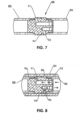
- the guide rod 82 of the present disclosure in one embodiment includes three separate (split) elements ( FIG. 5 ) that are preferably threaded together to form guide rod 82. These elements include a first guide rod segment 85, second guide rod segment 87 and a piston 88.
- This split embodiment allows for the hydraulic functions of cylinder 80 to be routed through piston 88 as a manifold in order to move the associated (required) hydraulic connections away from the outside of the cylinder where they are more susceptible to damage.
- Piston 88 includes an internally ported body with machined in sealing features for proper hydraulic functions.
- Hydraulic cylinder tube 84 is preferably a composite tube for encasing the hydraulic cylinder piston/guide rod.
- Rod gland 86 and 88 on each end of cylinder tube 84 seals on the cylinder rod and cylinder tube and seals the cylinder tube.
- the rod gland also pilots on the cylinder bore to properly align the carriage jaws.
- the tie rods connect the two rod glands at the ends of the cylinder tube.
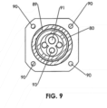
- Cylinder tube 84 is adapted for reciprocal travel along guide rod 82. As hydraulic fluid flows into an annular area defined between hydraulic cylinder tube 84 and guide rod 82, hydraulic cylinder tube 84 and rod glands 86, 88 (with jaws attached) will reciprocate back and forth. This is accomplished because first hydraulic fluid chamber 89 (and port 91 therefor) is separated from a second hydraulic fluid chamber 92 (and port 93 therefor) via a seal 94 to separate first 89 and second 90 annular hydraulic fluid chambers of the cylinder 80.
- the combined hydraulic cylinder and guide rod of the present disclosure is self-contained and when adapted for the modular carriage 10 described above with respect to FIGs. 1-3 , does not require bolts to be inserted through jaws 12, 14, and 16 as is the case with certain prior art hydraulic cylinder designs.
- the moveable jaws 14 and 16 are attached to rod glands 86 and 88, respectively, with latch mechanisms 44 and 52.
- FIG. 12 is an isometric view of the carriage assembly 10 of the present disclosure as depicted in FIG. 1 with the exception that clamps 28, 30, 40, 42, 44, 46, 52, and 54 of FIG. 1 have been replaced with a slightly modified embodiment clamps 28a, 30a, 40a, 42a, 44a, 46a, 52a, and 54a.
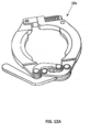
- new clamps 28a, (and 30a, 40a, 42a, 44a, 46a, 52a, and 54a) has been modified so as to provide a spring on the pivot end and a modified latch mechanism which does not protrude from the exterior of the clamp.
- FIG. 13 is the exploded view of FIG. 2 again modified to include modified clamps 28a, 30a, 40a, 42a, 44a, 46a, 52a, and 54a.
- FIG. 14 depicts a skid 150 configured to receive carriage assembly 10 of the present disclosure.
- Skid 150 is comprised of a substantially rectangular frame in a preferred embodiment.
- the frame includes stabilizer feet 174 and 176 separated by a plurality of longitudinal segments 162, 164, 166, and 168.
- Each of longitudinal segments 162, 164, 166, and 168 are secured to a respective foot 174 or 176 on one end and a joint, either joint 170 as in the case of longitudinal segments 162 and 166 or joint 172 as in the case of longitudinal segments 164 and 168.
- the skid 150 includes a plurality of cradles 156, 158, and 160 such that, in a preferred arrangement, cradle 156 is positioned over stabilizer foot 174 while cradle 160 is positioned over an adjacent stabilizer foot 176.
- Cradle 158 spans longitudinal segment 166 and 168 and is spaced a distance from cradle 160.
- Cradles 156, 158, and 160 are designed to receive skid interfaces 152 and 154 of FIG. 12 .
- Skid 150 is designed to pivot flat and pin rigidly with use of a plurality of detent pins, collectively 178.
- pins 178 can be removed from joints 170, 172 such that skid 150 can be folded over itself as depicted in FIGs. 15 and 16 .
- Cradles 156, 158, and 160 include a plurality of D-shaped cams, collectively 180, which are articulated through the use of respective rotation levers, collectively, 182 in order to secure carriage 10 of the present disclosure to provide a stable platform.
- FIG. 15 depicts skid 150 in a folded, shipping configuration.
- longitudinal segments 166 and 168 are pivoted over longitudinal segments 162 and 164 respectively at joints 170 and 172.
- pins 178 are removed from joints 170 and 172 and may be inserted into longitudinal segments 162, 164, 166 and 168 for safekeeping during transport.
- Longitudinal segments 166 and 168 are by design in a preferred arrangement slightly longer than longitudinal segments 162 and 164 such that when longitudinal segments 166 and 168 are folded over longitudinal segments 162 and 164 at joints 170 and 172, cradle 160 interlocks (nests) with cradle 156 and is secured therein.
- cradle 156 includes receiver segments 157, collectively, which receive pins 180 of cradle 160. Once D-shaped cams 180 are received in segments 157, levers 182 are rotated 180 degrees so as to secure and nest cradle 160 into cradle 156.
- FIG. 16 is a view of the folded cradle 150 of FIG. 15 rotated approximately 90 degrees in order to illustrate the unfolding procedure.
- rotation levers 182 are rotated 180 degrees so as to release D-shaped cams from nesting segments 157 ( FIG. 14 ).
- stabilizer foot 174, as well as longitudinal segments 166 and 167 may be rotated flat at joints 170 and 172 as depicted in FIG. 17 and arrow 186.
- detent pins 178 are once again inserted into joints 170, 172 and through respective longitudinal segments 162, 164, 166, or 168 so as to secure skid 150 in a flat or open position.
- carriage assembly 10 of the present disclosure may be secured to skid 150 by inserting skid interfaces 152 and 154 ( FIG. 12 ) into cradles 156, 158, respectively.
- Rotation levers 182 are then rotated so as to rotate D-shaped cams 180 to secure skid interface 152 with cradle 158 and skid interface 154 in cradle 156.
- a fourth jaw 190 having a skid interface 191 may be added for stability.
- Fourth jaw 190 may be inserted such that skid interface 191 is inserted into cradle 160 and secured therein via D-shaped cams 180 via rotation levers 182.
- the fourth jaw 190 may be used in conjunction with the carriage assembly 10 of the present disclosure to create a four jaw carriage which may be used when fusing pipe on the ground in a traditional manner.
- the fourth jaw 190 provides additional stability such that a four jaw skid allows a stable base that may allow more precise alignment of pipe than a three jaw configuration.
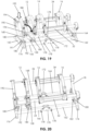
- a plurality of jaw braces 194 may bridge between fourth jaw 190 and jaw 12 and are secured as depicted in arrows 192 and 193.
- FIG. 21 is an enlarged view of fourth jaw 190 including its associated skid interface 191 positioned in cradle 160.
- FIG. 21 depicts D-shaped cam positioned in an unlocked state for insertion and removal of skid interface 191 into cradle 160.
- Rotation lever 182 is depicted to include a locking mechanism 196 to prevent unintentional unlocking.
- FIG. 22 depicts the opposite end of the assembly of FIG. 21 in a close up wherein a partial cutaway showing a cam slot 198 created in skid interface 191 into which D-shaped cam 180 is positioned.
- D-shaped cam 180 is in the unlocked position such that skid interface 191 may be lifted such that D-shaped cam is protracted out of cam slot 198.
- FIG. 23 depicts the close up view of the assembly of FIG. 21 except in a locked position such that rotation lever 182 is rotated approximately 180 degrees which in turn rotates D-shaped cam 180 within cam slot 198.
- FIG. 24 depicts the view of the assembly of FIG. 22 showing D-shaped cam 180 rotated into a locked position such that it is secured against an eccentric segment of cam slot 198. In this position, skid interface 191 cannot be pulled away from or separated from cradle 160.
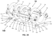
- FIG. 25 is an isometric view of the carriage assembly 10 of the present disclosure in a four jaw embodiment secured to a skid 150 as fully assembled. As shown, skid 150 is in an open or flat position so as to receive skid interfaces 152, 154, and 191.
- Methods of the present disclosure may be implemented by performing or completing manually, automatically, or a combination thereof, selected steps or tasks.
- method may refer to manners, means, techniques and procedures for accomplishing a given task including, but not limited to, those manners, means, techniques and procedures either known to, or readily developed from known manners, means, techniques and procedures by practitioners of the art.
- the term "at least” followed by a number is used herein to denote the start of a range beginning with that number (which may be a range having an upper limit or no upper limit, depending on the variable being defined). For example, “at least 1” means 1 or more than 1.
- the term “at most” followed by a number is used herein to denote the end of a range ending with that number (which may be a range having 1 or 0 as its lower limit, or a range having no lower limit, depending upon the variable being defined). For example, “at most 4" means 4 or less than 4, and "at most 40%” means 40% or less than 40%.
- a range is given as "(a first number) to (a second number)" or "(a first number) - (a second number)"
- 25 to 100 should be interpreted to mean a range whose lower limit is 25 and whose upper limit is 100.
- every possible subrange or interval within that range is also specifically intended unless the context indicates to the contrary.
- ranges for example, if the specification indicates a range of 25 to 100 such range is also intended to include subranges such as 26-100, 27-100, etc., 25-99, 25-98, etc., as well as any other possible combination of lower and upper values within the stated range, e.g., 33-47, 60-97, 41-45, 28-96, etc.
- integer range values have been used in this paragraph for purposes of illustration only and decimal and fractional values (e.g., 46.7 - 91.3) should also be understood to be intended as possible subrange endpoints unless specifically excluded.
Landscapes
- Engineering & Computer Science (AREA)
- Mechanical Engineering (AREA)
- Physics & Mathematics (AREA)
- Fluid Mechanics (AREA)
- Lining Or Joining Of Plastics Or The Like (AREA)
- Supports For Pipes And Cables (AREA)
- Earth Drilling (AREA)
Description
- The present invention relates to carriage assemblies for fusing two ends of polymer pipe.
- The principle of heat fusion is to heat two pipe surfaces to a designated temperature, and then fuse them together by application of force. This develops pressure which causes flow of the melted materials. Flow of the melted materials, causes mixing and thus fusion. When thermoplastic material is heated, the molecular structure is transformed into an amorphous condition. When fusion pressure is applied, the molecules from each thermoplastic part mix. As the joint cools, the molecules return to their form, the original interfaces are gone, and the fitting and pipe have become one monolithic unit. A strong, fully leak tight connection is the result. In general, there are considered to be seven principal operations. Clamping - the pipe pieces are held axially and radially to allow all subsequent operations to take place. Facing - the pipe ends are faced to establish clean, parallel mating surfaces perpendicular to the centerline of the pipes. Aligning - the pipe ends are aligned with each other to minimize mismatch of the pipe walls. Heating - a melt pattern that penetrates into the pipe is formed around both pipe ends. Fusing - the melt patterns are joined with a specified force, which is constant around the pipe interfacial area. Cooling - the fusion joint is held immobile with a specified force until adequately cooled. Inspecting - visually examining the entire circumference of the joint for compliance with the standard or fusion procedure used. Carriage devices for clamping and aligning the pipe pieces so that facing, heating, fusing, and cooling of the pipe can be accomplished are known in the art. Such devices are commonly large or mounted on a heavy frame. However, It is often the case that the work site is located in a very confined space, where a large, wheeled, assembled carriage cannot be manipulated. Existing pipe fusion apparatus such as that disclosed in
U.S. Patent No. 3,729,360 ,3,789,493 ,5,743,992 , and5,814,182 are large, wheeled, fixed mechanisms. The pipe clamps are fixed and are not capable of tool free engagement and removal. Each of these machines are not modular and cannot be disassembled without tools and reassembled in a confined work space. A need, therefore, exists for a carriage and clamping apparatus wherein its components can be separately carried to and/or positioned in a work site and put together quickly, at the fusion site without tools. For example, a need exists for a modular carriage assembly which could be used for repairing a section of pipe located within a wall of a building. - In a first aspect of the invention there is provided a modular carriage for varying spacing between ends of polymer pipe during fusion according to claim 1. The carriage of the present disclosure is part of a fusion system that is designed to be modular and light weight in order to easily use in tight spaces. The disclosure includes a modular carriage where the jaws are removable preferably without the requirement of tools in order to allow the carriage to be assembled on existing pipe that is in place in the rafters or running up a wall of a structure. For the purpose of exemplification, and not limitation, the carriage of the present disclosure may be sized to accommodate six different sizes of pipe for which butt fusion is required: 1) 355mm; 2) 400mm; 3) 450mm; 4) 500mm; 5) 560mm; or 6) 630mm.
- Each of these exemplary sizes requires its own size jaws and guide rod support. The hydraulic cylinders and guide rods of the present disclosure are able to be used on all sizes of the carriage system for the above examples. This allows a cost reduction and increase in the flexibility of the fusion system. This increased flexibility is characterized by the ability to:
- 1.) Break the unit down for easier storage and shipment;
- 2.) Customize the particular carriage assembly for a particular work space size and pipe size requirement;
- 3.) Customize the equipment sent to a job site in order to limit unnecessary parts;
- 4.) Move the carriage with ease in buildings and other structures;
- 5.) Assemble the carriage at the site of use of the carriage and particularly in work/pipe locations that are too tight for the use of a conventional fusion machine.
- Additional benefits of the modular carriage of the present disclosure include:
- 1.) Reduced weight of components that must be transported to/moved and/or lifted to the location of the pipe fusion;
- 2.) The modular design allows for the carriage of the present disclosure to be assembled directly on existing pipes that are already in place;
- 3.) Having a jaw for each size of pipe reduces the required spatial envelope for the carriage which allows the machine to fuse pipes that are spaced much closer to each other;
- 4.) Allows the possibility for reduced shipping size as the component (modular) parts are able to be disassembled and nested in shipping packaging.
- The carriage of the present disclosure is configurable so that the right size tools for any specific fusion requirement are present on a job site, even when different sizes of pipes are presented.
- The carriage assembly of the present disclosure includes in one embodiment, generally, a fixed jaw; moveable inner jaw and moveable outer jaw, and a guide preferably for each size of pipe. In addition, a combined hydraulic carriage cylinder and associated guide rod may be included. In this embodiment the hydraulic carriage cylinder/guide rod; a guide rod cap, and a guide rod sleeve may also be provided and be the same and employed with all pipe and jaw sizes. In an alternate preferred embodiment, a fourth, fixed jaw is added for increased stability.
- The modular carriage of the present disclosure is adaptable for varying spacing between ends of polymer pipe during fusion. The present modular design allows for many different sizes of pipe to be fused with the same fusion apparatus without the use of inserts. As set forth above, the modular carriage includes in a basic embodiment a fixed jaw; an inner and outer movable jaw; and a plurality of guide rods. The fixed jaw is adapted for tool free engagement with the plurality of guide rods. A carriage cylinder is associated with each of at least two of the guide rods. The carriage cylinder is mounted for reciprocal travel on its associated guide rod. Each movable jaw is adapted for tool free engagement with a cylinder for reciprocal travel therewith. Each moveable jaw is preferably adapted for engagement with at least two carriage cylinders for alignment and stability purposes.
- The guide rods each include a longitudinal axis. Each associate carriage cylinder also includes a longitudinal axis which is concentric with the longitudinal axis of its associated guide rod.
- A guide rod support is adapted for tool free engagement preferably with at least two of the plurality of guide rods. A latching assembly is operable to secure the guide rod support to the guide rods by tool free engagement. The movable jaws include at least two latching assemblies being operable to secure each movable jaw to at least two carriage cylinders by tool free engagement.
- The fixed jaw includes at least two latching assemblies being operable to secure the fixed jaw to at least two guide rods by tool free engagement.
- The plurality of guide rods are each substantially cylindrical with an external surface and an internal surface. The guide rods each include a first end and a second end. A guide rod sleeve is positioned at least partially over the external surface of each guide rod adjacent its first end. The fixed jaw is secured to the plurality of guide rods adjacent their first end. A guide rod cap is in contact with (threaded into) the internal surface at the first end. The fixed jaw is positioned between the guide rod sleeve and the guide rod cap and secured by the latching mechanism.
- Each guide rod sleeve may include a shoulder for retaining the guide rod sleeve adjacent the first end of its respective guide rod.
- Each carriage cylinder may be hydraulically actuated for reciprocal travel on its associated guide rod. Each of the plurality of guide rods has a length and each carriage cylinder has a length and two ends. Each carriage cylinder may surround its associated guide rod. The length of each carriage cylinder is less than the length of its associated guide rod so as to allow reciprocal hydraulic travel of each carriage cylinder along the length of its associated guide rod.
- Each carriage cylinder may include a rod gland at each end. Each rod gland is operable to hydraulically seal the carriage cylinder at each end. The rod gland surrounds its associated guide rod. Each rod gland includes a channel for receiving and supporting a movable jaw. As stated previously, in one embodiment there are two moveable jaws, an inner moveable jaw and an outer moveable jaw. In a preferred embodiment each moveable jaw is supported.
- A latching mechanism secures the moveable jaws. The movable jaw is secured in the channel by the latching mechanism. In a preferred arrangement the latching mechanism is a lock over (also known as a cam over) clamp. Thus, the movable jaws are secured to the rod glands by tool free engagement.
- The rod glands are mounted on the carriage cylinder so as to maintain the first movable jaw and the second movable jaw in a parallel orientation. A movable jaw (inner or outer) is secured to a rod gland at each opposing end of each of at least two guide rods. In one embodiment, two carriage cylinders, one of each of the at least two guide rods are positioned substantially parallel to one another.
- The carriage cylinder of the present invention may employ a cylinder assembly which may be of a known design. The cylinder may be powered in any known manner, such as pneumatically, or hydraulically.
- One particularly suited cylinder design, however, includes a combination hydraulic cylinder/guide rod of the present disclosure. The cylinder includes in one embodiment a guide rod; cylinder tube; a rod gland on each end of the cylinder tube; and a plurality of the rods extending between the rod glands.
- The piston includes an internally ported body with machined in sealing features for proper hydraulic functions.
- The hydraulic cylinder tube is preferably a composite tube for encasing the hydraulic cylinder. The rod gland on each end of the cylinder tube seals on the cylinder rod and cylinder tube and seals the cylinder tube. The rod gland also pilots on the cylinder bore to properly align the carriage jaws. The tie rods connect the two rod glands at the ends of the cylinder tube.
- The guide rod of the present disclosure in one embodiment includes three separate elements that are preferably threaded together to form the guide rod/cylinder rod and piston. This split embodiment allows for the hydraulic functions of the carriage to be routed through the piston as a manifold in order to move the associated (required) hydraulic connections away from the outside of the cylinder where they are more susceptible to damage.
- The cylinder tube is adapted for reciprocal travel along a guide rod. As hydraulic fluid flows into an annular area defined between the hydraulic cylinder tube and the split guide rod, the hydraulic cylinder tube and rod glands (with jaws attached) will reciprocate back and forth. This is accomplished because one hydraulic fluid chamber (and port therefor) is separated from a second hydraulic fluid chamber (and port therefor) via a seal to separate the first and second annular hydraulic fluid chambers of the cylinder.
- The combined hydraulic cylinder and guide rod of the present disclosure is self-contained and when adapted for the modular carriage described above, does not require bolts to be inserted through the jaws as is the case with certain prior art hydraulic cylinder designs. The present cylinders are attached to the moveable jaws with the clamp attachment assembly directly.
- Each carriage cylinder may be hydraulically actuated for reciprocal travel on its associated guide rod. Each of the plurality of guide rods has a length and each carriage cylinder has a length and two ends. Each carriage cylinder may surround its associated guide rod. The length of each carriage cylinder is less than the length of its associated guide rod so as to allow reciprocal hydraulic travel of each carriage cylinder along the length of its associated guide rod.
- Each carriage cylinder may include a rod gland at each end. Each rod gland is operable to hydraulically seal the carriage cylinder at each end. The rod gland surrounds its associated guide rod. Each rod gland includes a channel for receiving and supporting a movable jaw. As stated previously, in one embodiment there are two moveable jaws, an inner moveable jaw and an outer moveable jaw. In a preferred embodiment each moveable jaw is supported.
- A latching mechanism secures the moveable jaws. The movable jaw is secured in the channel by the latching mechanism. In a preferred arrangement the latching mechanism is a lock over (also known as a cam over) clamp. Thus, the movable jaws are secured to the rod glands by tool free engagement.
- The rod glands are mounted on the carriage cylinder so as to maintain the first movable jaw and the second movable jaw in a parallel orientation. A movable jaw (inner or outer) is secured to a rod gland at each opposing end of each of at least two guide rods. In one embodiment, two carriage cylinders, one of each of the at least two guide rods are positioned substantially parallel to one another.
- It should be understood that carriage cylinders of the carriage of the present disclosure described above may employ a cylinder assembly which may be of a known design. The cylinder may be powered in any known manner, such as pneumatically, or hydraulically.
- The cylinder tube is adapted for reciprocal travel along a guide rod. As hydraulic fluid flows into an annular area defined between the hydraulic cylinder tube and the split guide rod, the hydraulic cylinder tube and rod glands (with jaws attached) will reciprocate back and forth. This is accomplished because one hydraulic fluid chamber (and port therefor) is separated from a second hydraulic fluid chamber (and port therefor) via a seal to separate the first and second annular hydraulic fluid chambers of the cylinder.
- The combined hydraulic cylinder and guide rod of the present disclosure is self-contained and when adapted for the modular carriage described above, does not require bolts to be inserted through the jaws as is the case with certain prior art hydraulic cylinder designs. The present cylinders are attached to the moveable jaws with the clamp attachment assembly directly.
- Some, non-limiting benefits of the present combined hydraulic cylinder/guide rod assembly designs include:
- 1.) The combination cylinder/guide rod assembles in the carriage without the use of any hand or power tools;
- 2.) A self-contained design as described herein does not require the jaws (fixed and moveable) to be bolted to the ends to remain assembled.
- 3.) The design of the present disclosure allows for a small annular area for the cylinder (as compared to other known piston attachment methods which take up considerable space);
- 4.) A lower cost to manufacture is associated with the present design (lower cost than machining stock material down to add all of the piston features/required elements);
- 5.) The piston is able to be easily machine as a manifold allowing the hydraulic porting to be done through the hollow cylindrical guide rods;
- 6.) The hydraulic cylinder/guide rod assembly of the present disclosure includes features that ensure concentricity of the guide rod to provide jaw alignment for proper fusions and to reduce cylinder drag.
- A fourth jaw and a skid, when used in conjunction with the three jaw skid, create a four jaw carriage that may be used when fusing on the ground in a traditional manner. The four jaw skid provides a stable base that allows precise alignment of pipe with minimum effort. The three jaw carriage and the outer fixed jaw attach to the skid in a tool less manner through the use of interlocking D-shaped cams. The outer fixed jaw (fourth jaw) is attached to the inner fixed jaw (third jaw) with the usage of two jaw braces.
- The skid is comprised of two sections that can be folded flat and pinned rigidly in the flat configuration with the use of four detent pins, or can be folded in half and latched in the closed position using the same D-shaped cams that latch the carriage into the skid. The folding of the skid allows for shipping the carriage in a compact manner. The ability to fold the skid allows the entire package to be packed into four foot shipping pallets.
- Benefits of the fourth jaw and skid include the following, without limitation:
- 1.) A fourth jaw and a skid may be used in conjunction with a three jaw carriage.
- 2.) The assembly/connection of the jaws to the skid, the jaws to the guide rod(s) and/or jaw(s) to each other is toolless.
- 3.) The carriage, and particularly the carriage mounted to the skid, provides a stable base for conventional fusion of pipe.
- 4.) The addition of a fourth jaw eases alignment of one pipe to another through the use of two jaws per side.
- 5.) The carriage assembly, particularly with the additional fourth jaw, provides increased clamping force for retention of pipe during high force fusion.
- 6.) D-shaped cams connect the jaws to the skid.
- 7.) D-shaped cams lock the skid together when folded for shipping.
- 8.) A Folding skid allows for compact shipment of the carriage assembly package.
- 9.) A Folding skid can be pinned in a rigid configuration to provide a stable base for fusion.
- 10.) A Spring plunger is used to ensure the D-shaped cam does not disengage during use
-
-
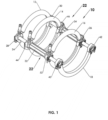
FIG. 1 depicts an isometric view of the carriage of the present disclosure. -
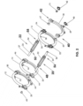
FIG. 2 depicts an exploded view of the carriage of the present disclosure. -
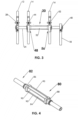
FIG. 3 depicts a side view of the carriage of the present disclosure. -
FIG. 4 depicts an isometric view of the combined hydraulic cylinder/guide rod of the present disclosure. -
FIG. 5 depicts a longitudinal cut-away side view of the guide rod assembly of the combined hydraulic cylinder/guide rod of the present disclosure. -
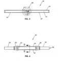
FIG. 6 depicts a side view of the combined hydraulic cylinder/guide rod of the present disclosure. -
FIG. 7 is an enlarged section detailed view 7 ofFIG. 5 . -
FIG. 8 is an enlarged partial view ofdetail 8 ofFIG. 5 depicting the combined hydraulic cylinder/guide rod of the present disclosure and specifically the hydraulic flow path through the piston. -
FIG. 9 is a cross-sectional view of the combined hydraulic cylinder/guide rod of the present disclosure taken along line 9-9 ofFIG. 6 . -
FIG. 10 is a cut-away side view of the latch assembly depicting attachment of a fixed jaw to an end of a guide rod. -
FIG. 11 is a cut-away side view of the latch assembly depicting attachment of a moveable jaw to a rod gland sealing an end of the hydraulic cylinder and surrounding the guide rod. -
FIG. 12 alternative embodiment isometric view of the carriage ofFIG. 1 depicting an alternate clamp design. -
FIG. 12A depicts the alternate clam design ofFIG. 12 . -
FIG. 13 depicts an exploded view of the alternate embodiment carriage ofFIG. 12 . -
FIG. 14 is an isometric view of the skid used to support the carriage of the present disclosure. -
FIG. 15 is an isometric view of the skid ofFIG. 14 in a folded configuration for packaging and shipment. -
FIG. 16 depicts the folded skid ofFIG. 14 oriented 90 degrees depicting the latches used to unfold the skid. -
FIG. 17 depicts the skid ofFIG. 14 unfolded in a flat configuration. -
FIG. 18 is an isometric view of the carriage assembly of the present disclosure inserted into the unfolded skid ofFIG. 16 . -
FIG. 19 is an isometric view of the carriage assembly inserted into a skid with a fourth jaw added. -
FIG. 20 is an isometric top view of the skid of the carriage assembly of the present disclosure inserted into a skid with a fourth jaw depicting the latching points. -
FIG. 21 is a close up view of the latching mechanism ofFIG. 20 depicting the D-shaped cam in an unlocked position for loading the fourth jaw into the skid. -
FIG. 22 is a close up view of the D-shaped cam ofFIG. 21 in an unlocked position. -
FIG. 23 is an isometric close up view of the latching mechanism in a locked position. -
FIG. 24 is the D-shaped cam ofFIGs. 23 and25 depicted in a locked position. -
FIG. 25 is an isometric view of the carriage of the present disclosure depicted with a fourth jaw and secured to a skid. - The embodiments herein and the various features and advantageous details thereof are explained more fully with reference to the non-limiting embodiments that are illustrated in the accompanying drawings and detailed in the following description. Descriptions of well-known components and processes and manufacturing techniques are omitted so as to not unnecessarily obscure the embodiments herein. The examples used herein are intended merely to facilitate an understanding of ways in which the invention herein may be practiced and to further enable those of skill in the art to practice the embodiments herein. Accordingly, the examples should not be construed as limiting the scope of the claimed invention.
- This present disclosure in one embodiment discloses the modular carriage assembly as a three jaw unit and including its modular components as well as general how the carriage assembles. It is the modular design that allows for many different sizes of pipe to be fused with the same fusion system without the use of inserts. In an alternate preferred embodiment, a fourth jaw may be added as described below.
- With reference to
FIGs. 1-3 , the modular carriage assembly of thepresent disclosure 10 includes in one embodiment, generally, a fixedjaw 12; moveableinner jaw 14, moveableouter jaw 16, and aguide 18 preferably for each size of pipe. In addition, two combined hydraulic carriage cylinder/guide rod assemblies -
Modular carriage 10 of the present disclosure is adaptable for varying spacing between ends of polymer (polyolefin) pipe during fusion. The present modular design ofcarriage 10 allows for many different sizes of pipe to be fused with the same fusion apparatus without the use of inserts. - With specific reference to
FIGs. 2 and3 , as set forth above, the modular carriage includes in a basic embodiment fixedjaw 12; an innermoveable jaw 14 and outermovable jaw 16; and twocylinder assemblies hydraulic cylinder assemblies guide rod guide rods latch assemblies 28 and 30 (discussed further below). Acarriage cylinder guide rods Carriage cylinders guide rod movable jaw 14 is adapted for tool free engagement withcylinders moveable jaw 16 is adapted for tool free engagement withcylinders moveable jaw carriage cylinders -
Guide rods carriage cylinder guide rod 24 and 26 (discussed further below). -
Guide rod support 18 is adapted for tool free engagement with second ends 36 and 38 ofguide rods assemblies guide rods movable jaw 14 includes twolatching assemblies movable jaw 14 onto first ends 48 and 50 ofcarriage cylinders Inner jaw 16 includes twolatching assemblies inner jaw 16 onto second ends 56 and 58 ofcarriage cylinders -
Guide rods external surface 60 andinternal surface 62 ofguide rod 24 depicted inFIG. 5 ). Aguide rod sleeve internal surface 62 at first ends 25 and 27. Fixedjaw 12 is positioned betweenguide rod sleeve mechanisms - Each guide rod sleeve such as
sleeve 64 ofFIG. 10 , may include ashoulder 72 for retaining theguide rod sleeve 64 adjacent thefirst end 25 of itsrespective guide rod 24.Carriage cylinders guide rod - Latching
mechanisms moveable jaw 14.Movable jaw 14 is secured in a channel by the latching mechanism (FIG. 11 ). In a preferred embodiment the latching mechanism is a lock over (also known as a cam over)clamp 28a (Figure 12a ). Thus,movable jaw 14 is secured to the first ends 48 and 50 ofcylinders - Latching
mechanisms moveable jaw 16 to theends cylinders Moveable jaw 16 is secured in a channel in the same way asjaw 14 ofFIG. 11 and described above.Moveable jaw 16 is secured to second ends 56 and 58 ofcylinders 32 byclamps - With reference to
FIG. 10 , anembodiment latching assembly 28 for securing fixedclamp 12 to theend 25 ofguide rod 24 by tool free engagement according to the present disclosure shall next be described.Sleeve 64 is secured overend 25 ofguide rod 24.Sleeve 64 includes ashoulder 72 retainingsleeve 64 from being forced overend 25.Sleeve 64 includes a second wall 122. Fixedjaw 12 is then placed oversleeve 64.Cap 68 is then threaded insidesurface 62 ofend 25.Cap 68 includes afirst wall 110.Sleeve 64 andcap 68 together define achannel 112 for receiving fixedjaw 12. Fixedjaw 12 is in contact withsecond wall 108 and adapted to transfer force tosecond wall 108.First wall 110 includes atapered surface 116 which mates the taper of taperedsurface 118 of a clampingsegments clamp 113. -
Latching mechanism 102 includes clamp 136 adapted to exert a clamping force uponmoveable jaw 100.Clamp 113 includes twoclamp segments interface tapered interface 131 offirst wall 130.Tapered interfaces interface 131 of thefirst wall 130. -
Clamp segments first wall 130 andmoveable jaw 100 and are adapted for transferring force from clamp 136 tomoveable jaw 100. Application of clamping force by clamp 136 onclamp segments tapered interface interface 131 offirst wall 130. This results in a force which translates fromclamp segments moveable jaw 100, and against second wall 132 thereby securingmoveable jaw 100, and clamp 136 withinchannel 134. - An identical latching mechanism 40 (
FIG. 1 ) securesguide 18 ontosecond end 36 in the same manner as fixedjaw 12. Second guide rod caps 69 and 71, secondguide rod sleeves FIG. 2 . - Next with reference to
FIG. 11 anexample latching mechanism 102 for securing an examplemoveable jaw 100 ofcarriage 10 is depicted in one embodiment employing the combination hydraulic cylinder tube/guide rod of the present disclosure and described below in relation toFIGs. 5-9 . As shown,cylinder tube 84 includesrod gland 86 onto which examplemoveable jaw 100 is secured.Rod gland 86 includes afirst wall 130 and second wall 132 defining achannel 134 therebetween for receiving at leastmoveable jaw 100 and clamp 136 of latchingmechanism 102. - It should be understood that
carriage cylinders - One particularly suited cylinder design in a preferred embodiment depicted in
FIGs. 4-9 , however, includes a novel combination hydraulic cylinder/guide rod which shall be next described.Cylinder 80 includes in one embodiment aguide rod 82;cylinder tube 84; arod gland cylinder tube 84; and a plurality of tie rods collectively 90, extending between therod glands FIGs. 1-3 , combination hydraulic cylinder/guide rod is employed ascylinders - The
guide rod 82 of the present disclosure in one embodiment includes three separate (split) elements (FIG. 5 ) that are preferably threaded together to formguide rod 82. These elements include a firstguide rod segment 85, secondguide rod segment 87 and apiston 88. This split embodiment allows for the hydraulic functions ofcylinder 80 to be routed throughpiston 88 as a manifold in order to move the associated (required) hydraulic connections away from the outside of the cylinder where they are more susceptible to damage.Piston 88 includes an internally ported body with machined in sealing features for proper hydraulic functions. -
Hydraulic cylinder tube 84 is preferably a composite tube for encasing the hydraulic cylinder piston/guide rod.Rod gland cylinder tube 84 seals on the cylinder rod and cylinder tube and seals the cylinder tube. The rod gland also pilots on the cylinder bore to properly align the carriage jaws. The tie rods connect the two rod glands at the ends of the cylinder tube. -
Cylinder tube 84 is adapted for reciprocal travel alongguide rod 82. As hydraulic fluid flows into an annular area defined betweenhydraulic cylinder tube 84 and guiderod 82,hydraulic cylinder tube 84 androd glands 86, 88 (with jaws attached) will reciprocate back and forth. This is accomplished because first hydraulic fluid chamber 89 (andport 91 therefor) is separated from a second hydraulic fluid chamber 92 (andport 93 therefor) via aseal 94 to separate first 89 and second 90 annular hydraulic fluid chambers of thecylinder 80. - The combined hydraulic cylinder and guide rod of the present disclosure is self-contained and when adapted for the
modular carriage 10 described above with respect toFIGs. 1-3 , does not require bolts to be inserted throughjaws moveable jaws rod glands latch mechanisms -
FIG. 12 is an isometric view of thecarriage assembly 10 of the present disclosure as depicted inFIG. 1 with the exception that clamps 28, 30, 40, 42, 44, 46, 52, and 54 ofFIG. 1 have been replaced with a slightly modified embodiment clamps 28a, 30a, 40a, 42a, 44a, 46a, 52a, and 54a. As depicted inFIG. 12A ,new clamps 28a, (and 30a, 40a, 42a, 44a, 46a, 52a, and 54a) has been modified so as to provide a spring on the pivot end and a modified latch mechanism which does not protrude from the exterior of the clamp.FIG. 13 is the exploded view ofFIG. 2 again modified to include modifiedclamps -
FIG. 14 depicts askid 150 configured to receivecarriage assembly 10 of the present disclosure.Skid 150 is comprised of a substantially rectangular frame in a preferred embodiment. The frame includesstabilizer feet longitudinal segments longitudinal segments respective foot longitudinal segments longitudinal segments skid 150 includes a plurality ofcradles cradle 156 is positioned overstabilizer foot 174 whilecradle 160 is positioned over anadjacent stabilizer foot 176.Cradle 158 spanslongitudinal segment cradle 160.Cradles skid interfaces FIG. 12 . -
Skid 150 is designed to pivot flat and pin rigidly with use of a plurality of detent pins, collectively 178. Alternatively, for the purpose of packaging and shipping in a compact arrangement, pins 178 can be removed fromjoints skid 150 can be folded over itself as depicted inFIGs. 15 and 16 . -
Cradles carriage 10 of the present disclosure to provide a stable platform. -
FIG. 15 depictsskid 150 in a folded, shipping configuration. As can be seen inFIG. 15 ,longitudinal segments longitudinal segments joints joints longitudinal segments Longitudinal segments longitudinal segments longitudinal segments longitudinal segments joints cradle 160 interlocks (nests) withcradle 156 and is secured therein. With reference back toFIG. 14 ,cradle 156 includesreceiver segments 157, collectively, which receivepins 180 ofcradle 160. Once D-shapedcams 180 are received insegments 157,levers 182 are rotated 180 degrees so as to secure andnest cradle 160 intocradle 156. -
FIG. 16 is a view of the foldedcradle 150 ofFIG. 15 rotated approximately 90 degrees in order to illustrate the unfolding procedure. As depicted, in order to unfoldskid 150 in a preferred arrangement, rotation levers 182 are rotated 180 degrees so as to release D-shaped cams from nesting segments 157 (FIG. 14 ). Once D-shapedcams 180 are released, or unlocked,stabilizer foot 174, as well aslongitudinal segments 166 and 167 may be rotated flat atjoints FIG. 17 andarrow 186. Once rotated flat, detent pins 178 are once again inserted intojoints longitudinal segments skid 150 in a flat or open position. - With reference to
FIG. 18 , onceskid 150 is positioned open or flat,carriage assembly 10 of the present disclosure may be secured to skid 150 by insertingskid interfaces 152 and 154 (FIG. 12 ) intocradles cams 180 to secureskid interface 152 withcradle 158 andskid interface 154 incradle 156. - With reference to
FIGs. 19 and 20 , in an alternate preferred embodiment, afourth jaw 190 having askid interface 191 may be added for stability.Fourth jaw 190 may be inserted such thatskid interface 191 is inserted intocradle 160 and secured therein via D-shapedcams 180 via rotation levers 182. Thefourth jaw 190 may be used in conjunction with thecarriage assembly 10 of the present disclosure to create a four jaw carriage which may be used when fusing pipe on the ground in a traditional manner. Thefourth jaw 190 provides additional stability such that a four jaw skid allows a stable base that may allow more precise alignment of pipe than a three jaw configuration. As depicted, a plurality of jaw braces 194 may bridge betweenfourth jaw 190 andjaw 12 and are secured as depicted inarrows -
FIG. 21 is an enlarged view offourth jaw 190 including its associatedskid interface 191 positioned incradle 160.FIG. 21 depicts D-shaped cam positioned in an unlocked state for insertion and removal ofskid interface 191 intocradle 160.Rotation lever 182 is depicted to include alocking mechanism 196 to prevent unintentional unlocking. -
FIG. 22 depicts the opposite end of the assembly ofFIG. 21 in a close up wherein a partial cutaway showing acam slot 198 created inskid interface 191 into which D-shapedcam 180 is positioned. As shown, D-shapedcam 180 is in the unlocked position such thatskid interface 191 may be lifted such that D-shaped cam is protracted out ofcam slot 198. -
FIG. 23 depicts the close up view of the assembly ofFIG. 21 except in a locked position such thatrotation lever 182 is rotated approximately 180 degrees which in turn rotates D-shapedcam 180 withincam slot 198. -
FIG. 24 depicts the view of the assembly ofFIG. 22 showing D-shapedcam 180 rotated into a locked position such that it is secured against an eccentric segment ofcam slot 198. In this position,skid interface 191 cannot be pulled away from or separated fromcradle 160. -
FIG. 25 is an isometric view of thecarriage assembly 10 of the present disclosure in a four jaw embodiment secured to askid 150 as fully assembled. As shown,skid 150 is in an open or flat position so as to receiveskid interfaces - It is to be understood that the terms "including", "comprising", "consisting" and grammatical variants thereof do not preclude the addition of one or more components, features, steps, or integers or groups thereof and that the terms are to be construed as specifying components, features, steps or integers.
- If the specification or claims refer to "an additional" element, that does not preclude there being more than one of the additional elements.
- It is to be understood that where the claims or specification refer to "a" or "an" element, such reference is not be construed that there is only one of that element.
- It is to be understood that where the specification states that a component, feature, structure, or characteristic "may", "might", "can" or "could" be included, that particular component, feature, structure, or characteristic is not required to be included.
- Methods of the present disclosure may be implemented by performing or completing manually, automatically, or a combination thereof, selected steps or tasks.
- The term "method" may refer to manners, means, techniques and procedures for accomplishing a given task including, but not limited to, those manners, means, techniques and procedures either known to, or readily developed from known manners, means, techniques and procedures by practitioners of the art.
- The term "at least" followed by a number is used herein to denote the start of a range beginning with that number (which may be a range having an upper limit or no upper limit, depending on the variable being defined). For example, "at least 1" means 1 or more than 1. The term "at most" followed by a number is used herein to denote the end of a range ending with that number (which may be a range having 1 or 0 as its lower limit, or a range having no lower limit, depending upon the variable being defined). For example, "at most 4" means 4 or less than 4, and "at most 40%" means 40% or less than 40%. Terms of approximation (e.g., "about", "substantially", "approximately", etc.) should be interpreted according to their ordinary and customary meanings as used in the associated art unless indicated otherwise. Absent a specific definition and absent ordinary and customary usage in the associated art, such terms should be interpreted to be ± 10% of the base value.
- When, in this document, a range is given as "(a first number) to (a second number)" or "(a first number) - (a second number)", this means a range whose lower limit is the first number and whose upper limit is the second number. For example, 25 to 100 should be interpreted to mean a range whose lower limit is 25 and whose upper limit is 100. Additionally, it should be noted that where a range is given, every possible subrange or interval within that range is also specifically intended unless the context indicates to the contrary. For example, if the specification indicates a range of 25 to 100 such range is also intended to include subranges such as 26-100, 27-100, etc., 25-99, 25-98, etc., as well as any other possible combination of lower and upper values within the stated range, e.g., 33-47, 60-97, 41-45, 28-96, etc. Note that integer range values have been used in this paragraph for purposes of illustration only and decimal and fractional values (e.g., 46.7 - 91.3) should also be understood to be intended as possible subrange endpoints unless specifically excluded.
- (0107)It should be noted that where reference is made herein to a method comprising two or more defined steps, the defined steps can be carried out in any order or simultaneously (except where context excludes that possibility), and the method can also include one or more other steps which are carried out before any of the defined steps, between two of the defined steps, or after all of the defined steps (except where context excludes that possibility).
- (0108)Thus, the present invention is well adapted to carry out the objects and attain the ends and advantages mentioned above as well as those inherent therein.
Claims (13)
- Modular carriage (10) for varying spacing between ends of polymer pipe during fusion, said modular carriage comprising:a fixed jaw (12);a movable jaw (14/16);a plurality of guide rods (24/26);said fixed jaw (12) being adapted for tool free engagement with and removal from said plurality of guide rods (24/26);a carriage cylinder (32/34) associated with at least two of said guide rods (24/26), said carriage cylinder (32/34) being mounted for reciprocal travel on its associated guide rod (24/26);said movable jaw (14/16) being adapted for tool free engagement with and removal from said at least one carriage cylinder (32/34) for reciprocal travel therewith, said guide rods (24/26) include a longitudinal axis and each said carriage cylinder (32/34) includes a longitudinal axis which is concentric with the longitudinal axis of its associated guide rod (24/26) and characterised in that said movable jaw (14/16) includes at least two latching assemblies (44/46/52/54) being operable to secure said movable jaw (14/16) to said carriage cylinders (32/34) by tool free engagement..
- The modular carriage (10) of claim 1 characterised by said modular carriage including a guide rod support (18) adapted for tool free engagement with said plurality of guide rods (24/26).
- The modular carriage (10) of claim 2 characterised by said modular carriage including a latching assembly (28) being operable to secure said guide rod (24/26) support to said plurality of guide rods (24/26) by tool free engagement.
- The modular carriage (10) of claim 1 characterised in that said fixed jaw (12) includes at least two latching assemblies being operable to secure said fixed jaw (12) to said plurality of guide rods (24/26) by tool free engagement.
- The modular carriage (10) of claim 4 characterised in that said plurality of guide rods (24/26) are each substantially cylindrical with an external surface (60) and an internal surface (62); and said plurality of guide rods (24/26) each include a first end (25/27) and a second end.
- The modular carriage (10) of claim 5 characterised in that said fixed jaw (12) is secured to said plurality of guide rods (24/26) adjacent their first end (25/27).
- The modular carriage (10) of claim 6 characterised by said modular carriage further including:a guide rod sleeve (64/66) positioned at least partially over said external surface (60) of each of said plurality of guide rods (24/26) adjacent said first end (25/27);a guide rod cap (68/70) in contact with said internal surface (62) at said first end (25/27); andsaid fixed jaw (12) being positioned between said guide rod sleeve (64/66) and said guide rod cap (68/70) and secured by said latching mechanism (28/30).
- The modular carriage (10) of claim 7 characterised in that each said guide rod sleeve (64/66) includes a shoulder (72) for retaining said guide rod sleeve (64) adjacent said first end (25) of its respective guide rod (24/26).
- The modular carriage (10) of claim 1 characterised in that each carriage cylinder (32/34) is in hydraulic communication with at least one hydraulic pump for reciprocal travel on its associated guide rod (24/26).
- The modular carriage (10) of claim 9 characterised by said modular carriage comprising:each of said plurality of guide rods (24/26) has a length and wherein each of said at least one carriage cylinder (32/34) has a length and two ends;each carriage cylinder (32/34) surrounds its associated guide rod (24/26);said length of each said at least one carriage cylinder (32/34) being less than the length of its associated guide rod (24/26) so as to allow reciprocal hydraulic reciprocal travel of each carriage cylinder (32/34) along the length of its associated guide rod (24/26).
- The modular carriage (10) of claim 10 characterised in that said carriage cylinder (32/34) includes a rod gland (86/88) at each end.
- The modular carriage (10) of claim 9 characterised by said modular carriage including a second movable jaw.
- The modular carriage (10) of claim 12 characterised by said modular carriage including two carriage cylinders positioned substantially parallel to one another.
Priority Applications (1)
| Application Number | Priority Date | Filing Date | Title |
|---|---|---|---|
| EP24172152.1A EP4424497A1 (en) | 2017-09-19 | 2018-09-19 | Modular carriage assembly for the fusion of polyolefin pipes |
Applications Claiming Priority (3)
| Application Number | Priority Date | Filing Date | Title |
|---|---|---|---|
| US201762560666P | 2017-09-19 | 2017-09-19 | |
| US201762561008P | 2017-09-20 | 2017-09-20 | |
| PCT/US2018/051747 WO2019060412A1 (en) | 2017-09-19 | 2018-09-19 | Modular carriage assembly for the fusion of polyolefin pipes |
Related Child Applications (2)
| Application Number | Title | Priority Date | Filing Date |
|---|---|---|---|
| EP24172152.1A Division-Into EP4424497A1 (en) | 2017-09-19 | 2018-09-19 | Modular carriage assembly for the fusion of polyolefin pipes |
| EP24172152.1A Division EP4424497A1 (en) | 2017-09-19 | 2018-09-19 | Modular carriage assembly for the fusion of polyolefin pipes |
Publications (2)
| Publication Number | Publication Date |
|---|---|
| EP3684599A1 EP3684599A1 (en) | 2020-07-29 |
| EP3684599B1 true EP3684599B1 (en) | 2024-06-05 |
Family
ID=64901058
Family Applications (2)
| Application Number | Title | Priority Date | Filing Date |
|---|---|---|---|
| EP24172152.1A Pending EP4424497A1 (en) | 2017-09-19 | 2018-09-19 | Modular carriage assembly for the fusion of polyolefin pipes |
| EP18826840.3A Active EP3684599B1 (en) | 2017-09-19 | 2018-09-19 | Modular carriage assembly for the fusion of polyolefin pipes |
Family Applications Before (1)
| Application Number | Title | Priority Date | Filing Date |
|---|---|---|---|
| EP24172152.1A Pending EP4424497A1 (en) | 2017-09-19 | 2018-09-19 | Modular carriage assembly for the fusion of polyolefin pipes |
Country Status (5)
| Country | Link |
|---|---|
| US (2) | US11312088B2 (en) |
| EP (2) | EP4424497A1 (en) |
| AU (2) | AU2018337819B2 (en) |
| CA (2) | CA3072815C (en) |
| WO (1) | WO2019060412A1 (en) |
Families Citing this family (10)
| Publication number | Priority date | Publication date | Assignee | Title |
|---|---|---|---|---|
| US10584808B1 (en) * | 2017-04-13 | 2020-03-10 | Jared Tanner | Pipe guide |
| CN110497619A (en) * | 2018-05-18 | 2019-11-26 | 中冶宝钢技术服务有限公司 | Plastic pipe hot-melt docking facilities and its operational method |
| TWI689386B (en) * | 2019-06-27 | 2020-04-01 | 和碩聯合科技股份有限公司 | Clamping device |
| CN111451956B (en) * | 2020-04-10 | 2021-09-10 | 山西远扬钢结构有限公司 | Manufacturing and processing method of pipe fitting steel structure |
| CN111497268A (en) * | 2020-04-30 | 2020-08-07 | 杨燕荷 | A hot-melt plastic pipe docking device suitable for multiple calibers |
| CN112606404B (en) * | 2020-12-30 | 2022-04-05 | 辽宁希泰科技有限公司 | Hot melt welding machine for corrugated pipe joint |
| CN112899814B (en) * | 2021-02-03 | 2022-12-06 | 广西大学 | A kind of bionic fiber functional material and its preparation method and application |
| CN112571806B (en) * | 2021-03-01 | 2021-05-07 | 烟台华港能源科技有限公司 | Butt joint fixing device for gas pipeline machining |
| CN114038662B (en) * | 2021-11-22 | 2024-11-05 | 中国南方电网有限责任公司超高压输电公司广州局 | Variable flow respirator replacement device |
| US20250297449A1 (en) * | 2024-03-22 | 2025-09-25 | Federal Signal Corporation | Digging lance with adjustable vavle handle & methods |
Citations (1)
| Publication number | Priority date | Publication date | Assignee | Title |
|---|---|---|---|---|
| DE2734910B1 (en) * | 1977-08-03 | 1978-09-28 | Dommer Soehne Widos | Device for butt welding of thermoplastic plastic pipes |
Family Cites Families (19)
| Publication number | Priority date | Publication date | Assignee | Title |
|---|---|---|---|---|
| US3729360A (en) * | 1971-03-08 | 1973-04-24 | A Mcelroy | Portable thermoplastic pipe fusion apparatus |
| US3789493A (en) | 1972-02-07 | 1974-02-05 | Ridge Tool Co | Hydraulic actuated fusion unit for plastic pipe |
| US4008118A (en) * | 1975-12-30 | 1977-02-15 | Emerson Electric Co. | Butt fusion machine |
| US4352708A (en) * | 1980-09-08 | 1982-10-05 | Mcelroy Arthur H | Defined force fusion machine for joining plastic pipe |
| US4990209A (en) * | 1986-06-27 | 1991-02-05 | Rakes George C | Self propelled pipe fusion machine |
| AU4254296A (en) * | 1994-11-21 | 1996-06-17 | Ulrike Richter | Butt-welding device for pipes made of thermoplastic materials |
| DE19601258A1 (en) * | 1995-01-17 | 1996-07-18 | Diebolt Int Inc | Turning journal fixing device for hydraulic cylinder |
| US5692285A (en) * | 1995-10-31 | 1997-12-02 | Workman Developments, Inc. | Butt fusion apparatus with means for changing quickly between straight pipe and pipe fitting attachment positions, and method |
| US5830312A (en) * | 1995-10-31 | 1998-11-03 | Hughes Supply, Inc. | Butt fusion apparatus with clamping jaws for clamping pipe to be fused without interference between the clamps and the pipe |
| US5743992A (en) * | 1995-10-31 | 1998-04-28 | Hughes Supply, Inc. | Butt fusion apparatus with constant pressure accumulator |
| US5770006A (en) * | 1997-01-13 | 1998-06-23 | Tdw Delaware, Inc. | Butt fusion machine for manufacturing full size segemented pipe turns |
| US5843271A (en) * | 1997-02-06 | 1998-12-01 | Tdw Delaware, Inc. | Plastic pipe butt fusion machine and cart assembly |
| US5814182A (en) * | 1997-09-19 | 1998-09-29 | Mcelroy Manufacturing, Inc. | Self-contained and self-propelled machine for heat fusing polyolefin pipes |
| US6550514B1 (en) * | 2000-03-29 | 2003-04-22 | Connectra Fusion Technologies, Llc | Indexer system for use with a plastic pipe butt-fusion machine |
| ITPD20070023A1 (en) * | 2007-01-29 | 2008-07-30 | Ritmo Spa | WAGON FOR THE TRANSPORT OF A WELDING MACHINE FOR WELDING HEAD OF PIPING PORTIONS |
| DE102010048612A1 (en) * | 2010-10-15 | 2012-04-19 | Rothenberger Ag | Method and device for welding pipe sections made of plastics to pipes |
| US9278441B2 (en) * | 2011-01-31 | 2016-03-08 | Lokring Technology, Llc | Installation tool for pipe fittings |
| US9242410B2 (en) * | 2013-09-17 | 2016-01-26 | Mcelroy Manufacturing, Inc. | Top-loading straddle-mounted pipe fusion machine |
| WO2017018961A2 (en) * | 2015-07-28 | 2017-02-02 | Ahmet Koyun | A butt welding machine with a cutter for a plastic pipe comprising a drive gear unit |
-
2018
- 2018-09-19 EP EP24172152.1A patent/EP4424497A1/en active Pending
- 2018-09-19 EP EP18826840.3A patent/EP3684599B1/en active Active
- 2018-09-19 CA CA3072815A patent/CA3072815C/en active Active
- 2018-09-19 US US16/135,306 patent/US11312088B2/en active Active
- 2018-09-19 AU AU2018337819A patent/AU2018337819B2/en active Active
- 2018-09-19 WO PCT/US2018/051747 patent/WO2019060412A1/en not_active Ceased
- 2018-09-19 CA CA3156481A patent/CA3156481A1/en active Pending
-
2022
- 2022-04-25 US US17/728,408 patent/US20220281179A1/en active Pending
-
2023
- 2023-07-12 AU AU2023204629A patent/AU2023204629A1/en not_active Abandoned
Patent Citations (1)
| Publication number | Priority date | Publication date | Assignee | Title |
|---|---|---|---|---|
| DE2734910B1 (en) * | 1977-08-03 | 1978-09-28 | Dommer Soehne Widos | Device for butt welding of thermoplastic plastic pipes |
Also Published As
| Publication number | Publication date |
|---|---|
| CA3072815C (en) | 2022-04-26 |
| EP3684599A1 (en) | 2020-07-29 |
| AU2018337819A1 (en) | 2020-03-05 |
| US20190210297A1 (en) | 2019-07-11 |
| US11312088B2 (en) | 2022-04-26 |
| AU2018337819B2 (en) | 2023-04-13 |
| CA3072815A1 (en) | 2019-03-28 |
| AU2023204629A1 (en) | 2023-08-03 |
| WO2019060412A1 (en) | 2019-03-28 |
| US20220281179A1 (en) | 2022-09-08 |
| CA3156481A1 (en) | 2019-03-28 |
| EP4424497A1 (en) | 2024-09-04 |
Similar Documents
| Publication | Publication Date | Title |
|---|---|---|
| CA3072815C (en) | Modular carriage assembly for the fusion of polyolefin pipes | |
| US11813804B2 (en) | Assembly and method of coupling pipes | |
| KR20210010838A (en) | Method and apparatus for precision manufacturing of moment joint assembly | |
| US3566505A (en) | Apparatus for aligning two sections of pipe | |
| US3920232A (en) | Apparatus for aligning pipe ends | |
| CZ138195A3 (en) | Press tool | |
| EP0852996B1 (en) | A butt fusion machine for manufacturing full size segmented pipe turns | |
| NO179052B (en) | Apparatus for centering a pipe part under a top drill for a drill | |
| EP0779465B1 (en) | Pipe repair clamp and method | |
| US20160356104A1 (en) | Apparatus to support a tubular member | |
| WO2018175566A2 (en) | Pipe repair system | |
| US20190301646A1 (en) | Apparatus and method for lined pipe welding | |
| US10151155B2 (en) | Modular carousel for a drilling rig | |
| CA2074189A1 (en) | Method/apparatus for detachably joining two members | |
| CN1705845A (en) | Quick connect and quick release safety connectors for pipes | |
| US10760723B2 (en) | Fluid system connection nozzle assembly | |
| CN108000043A (en) | A kind of pipeline welding gas protective device | |
| FI123807B (en) | Pipe joints and process for manufacturing a pipe joint | |
| US5464147A (en) | Method of connecting cylindrical members to each other using tandem type internal clamp | |
| KR200245809Y1 (en) | Jig of connection for pipe | |
| US4708330A (en) | Alignment and assembly tool for very large diameter cylinders | |
| JP3586329B2 (en) | Welding machine | |
| EP4069622B1 (en) | Spreader structures for lifting loads | |
| NO333634B1 (en) | Pipe connector for releasable connection of two connector parts in connection with gas-tight connection of risers to vessels | |
| GB2085347A (en) | Injection mould for coaxial cable jointing |
Legal Events
| Date | Code | Title | Description |
|---|---|---|---|
| STAA | Information on the status of an ep patent application or granted ep patent |
Free format text: STATUS: UNKNOWN |
|
| STAA | Information on the status of an ep patent application or granted ep patent |
Free format text: STATUS: THE INTERNATIONAL PUBLICATION HAS BEEN MADE |
|
| PUAI | Public reference made under article 153(3) epc to a published international application that has entered the european phase |
Free format text: ORIGINAL CODE: 0009012 |
|
| STAA | Information on the status of an ep patent application or granted ep patent |
Free format text: STATUS: REQUEST FOR EXAMINATION WAS MADE |
|
| 17P | Request for examination filed |
Effective date: 20200408 |
|
| AK | Designated contracting states |
Kind code of ref document: A1 Designated state(s): AL AT BE BG CH CY CZ DE DK EE ES FI FR GB GR HR HU IE IS IT LI LT LU LV MC MK MT NL NO PL PT RO RS SE SI SK SM TR |
|
| AX | Request for extension of the european patent |
Extension state: BA ME |
|
| DAV | Request for validation of the european patent (deleted) | ||
| STAA | Information on the status of an ep patent application or granted ep patent |
Free format text: STATUS: EXAMINATION IS IN PROGRESS |
|
| 17Q | First examination report despatched |
Effective date: 20210615 |
|
| P01 | Opt-out of the competence of the unified patent court (upc) registered |
Effective date: 20230522 |
|
| GRAP | Despatch of communication of intention to grant a patent |
Free format text: ORIGINAL CODE: EPIDOSNIGR1 |
|
| STAA | Information on the status of an ep patent application or granted ep patent |
Free format text: STATUS: GRANT OF PATENT IS INTENDED |
|
| RIC1 | Information provided on ipc code assigned before grant |
Ipc: F16L 47/02 20060101ALN20231212BHEP Ipc: F16L 1/10 20060101ALN20231212BHEP Ipc: B29L 23/00 20060101ALN20231212BHEP Ipc: B29K 23/00 20060101ALN20231212BHEP Ipc: B25B 5/14 20060101ALI20231212BHEP Ipc: B25B 5/06 20060101ALI20231212BHEP Ipc: B29C 65/78 20060101ALI20231212BHEP Ipc: B29C 65/02 20060101AFI20231212BHEP |
|
| INTG | Intention to grant announced |
Effective date: 20240102 |
|
| GRAS | Grant fee paid |
Free format text: ORIGINAL CODE: EPIDOSNIGR3 |
|
| GRAA | (expected) grant |
Free format text: ORIGINAL CODE: 0009210 |
|
| STAA | Information on the status of an ep patent application or granted ep patent |
Free format text: STATUS: THE PATENT HAS BEEN GRANTED |
|
| AK | Designated contracting states |
Kind code of ref document: B1 Designated state(s): AL AT BE BG CH CY CZ DE DK EE ES FI FR GB GR HR HU IE IS IT LI LT LU LV MC MK MT NL NO PL PT RO RS SE SI SK SM TR |
|
| REG | Reference to a national code |
Ref country code: CH Ref legal event code: EP |
|
| REG | Reference to a national code |
Ref country code: DE Ref legal event code: R096 Ref document number: 602018070360 Country of ref document: DE |
|
| REG | Reference to a national code |
Ref country code: IE Ref legal event code: FG4D |
|
| REG | Reference to a national code |
Ref country code: LT Ref legal event code: MG9D |
|
| PG25 | Lapsed in a contracting state [announced via postgrant information from national office to epo] |
Ref country code: BG Free format text: LAPSE BECAUSE OF FAILURE TO SUBMIT A TRANSLATION OF THE DESCRIPTION OR TO PAY THE FEE WITHIN THE PRESCRIBED TIME-LIMIT Effective date: 20240605 |
|
| REG | Reference to a national code |
Ref country code: NL Ref legal event code: MP Effective date: 20240605 |
|
| PG25 | Lapsed in a contracting state [announced via postgrant information from national office to epo] |
Ref country code: FI Free format text: LAPSE BECAUSE OF FAILURE TO SUBMIT A TRANSLATION OF THE DESCRIPTION OR TO PAY THE FEE WITHIN THE PRESCRIBED TIME-LIMIT Effective date: 20240605 Ref country code: HR Free format text: LAPSE BECAUSE OF FAILURE TO SUBMIT A TRANSLATION OF THE DESCRIPTION OR TO PAY THE FEE WITHIN THE PRESCRIBED TIME-LIMIT Effective date: 20240605 |
|
| PG25 | Lapsed in a contracting state [announced via postgrant information from national office to epo] |
Ref country code: GR Free format text: LAPSE BECAUSE OF FAILURE TO SUBMIT A TRANSLATION OF THE DESCRIPTION OR TO PAY THE FEE WITHIN THE PRESCRIBED TIME-LIMIT Effective date: 20240906 |
|
| PG25 | Lapsed in a contracting state [announced via postgrant information from national office to epo] |
Ref country code: ES Free format text: LAPSE BECAUSE OF FAILURE TO SUBMIT A TRANSLATION OF THE DESCRIPTION OR TO PAY THE FEE WITHIN THE PRESCRIBED TIME-LIMIT Effective date: 20240605 |
|
| PG25 | Lapsed in a contracting state [announced via postgrant information from national office to epo] |
Ref country code: LV Free format text: LAPSE BECAUSE OF FAILURE TO SUBMIT A TRANSLATION OF THE DESCRIPTION OR TO PAY THE FEE WITHIN THE PRESCRIBED TIME-LIMIT Effective date: 20240605 |
|
| PG25 | Lapsed in a contracting state [announced via postgrant information from national office to epo] |
Ref country code: NO Free format text: LAPSE BECAUSE OF FAILURE TO SUBMIT A TRANSLATION OF THE DESCRIPTION OR TO PAY THE FEE WITHIN THE PRESCRIBED TIME-LIMIT Effective date: 20240905 Ref country code: LV Free format text: LAPSE BECAUSE OF FAILURE TO SUBMIT A TRANSLATION OF THE DESCRIPTION OR TO PAY THE FEE WITHIN THE PRESCRIBED TIME-LIMIT Effective date: 20240605 Ref country code: HR Free format text: LAPSE BECAUSE OF FAILURE TO SUBMIT A TRANSLATION OF THE DESCRIPTION OR TO PAY THE FEE WITHIN THE PRESCRIBED TIME-LIMIT Effective date: 20240605 Ref country code: GR Free format text: LAPSE BECAUSE OF FAILURE TO SUBMIT A TRANSLATION OF THE DESCRIPTION OR TO PAY THE FEE WITHIN THE PRESCRIBED TIME-LIMIT Effective date: 20240906 Ref country code: FI Free format text: LAPSE BECAUSE OF FAILURE TO SUBMIT A TRANSLATION OF THE DESCRIPTION OR TO PAY THE FEE WITHIN THE PRESCRIBED TIME-LIMIT Effective date: 20240605 Ref country code: ES Free format text: LAPSE BECAUSE OF FAILURE TO SUBMIT A TRANSLATION OF THE DESCRIPTION OR TO PAY THE FEE WITHIN THE PRESCRIBED TIME-LIMIT Effective date: 20240605 Ref country code: BG Free format text: LAPSE BECAUSE OF FAILURE TO SUBMIT A TRANSLATION OF THE DESCRIPTION OR TO PAY THE FEE WITHIN THE PRESCRIBED TIME-LIMIT Effective date: 20240605 Ref country code: RS Free format text: LAPSE BECAUSE OF FAILURE TO SUBMIT A TRANSLATION OF THE DESCRIPTION OR TO PAY THE FEE WITHIN THE PRESCRIBED TIME-LIMIT Effective date: 20240905 |
|
| PG25 | Lapsed in a contracting state [announced via postgrant information from national office to epo] |
Ref country code: NL Free format text: LAPSE BECAUSE OF FAILURE TO SUBMIT A TRANSLATION OF THE DESCRIPTION OR TO PAY THE FEE WITHIN THE PRESCRIBED TIME-LIMIT Effective date: 20240605 |
|
| REG | Reference to a national code |
Ref country code: AT Ref legal event code: MK05 Ref document number: 1692160 Country of ref document: AT Kind code of ref document: T Effective date: 20240605 |
|
| PG25 | Lapsed in a contracting state [announced via postgrant information from national office to epo] |
Ref country code: NL Free format text: LAPSE BECAUSE OF FAILURE TO SUBMIT A TRANSLATION OF THE DESCRIPTION OR TO PAY THE FEE WITHIN THE PRESCRIBED TIME-LIMIT Effective date: 20240605 |
|
| PG25 | Lapsed in a contracting state [announced via postgrant information from national office to epo] |
Ref country code: PT Free format text: LAPSE BECAUSE OF FAILURE TO SUBMIT A TRANSLATION OF THE DESCRIPTION OR TO PAY THE FEE WITHIN THE PRESCRIBED TIME-LIMIT Effective date: 20241007 |
|
| PG25 | Lapsed in a contracting state [announced via postgrant information from national office to epo] |
Ref country code: PT Free format text: LAPSE BECAUSE OF FAILURE TO SUBMIT A TRANSLATION OF THE DESCRIPTION OR TO PAY THE FEE WITHIN THE PRESCRIBED TIME-LIMIT Effective date: 20241007 |
|
| PG25 | Lapsed in a contracting state [announced via postgrant information from national office to epo] |
Ref country code: PL Free format text: LAPSE BECAUSE OF FAILURE TO SUBMIT A TRANSLATION OF THE DESCRIPTION OR TO PAY THE FEE WITHIN THE PRESCRIBED TIME-LIMIT Effective date: 20240605 |
|
| PG25 | Lapsed in a contracting state [announced via postgrant information from national office to epo] |
Ref country code: EE Free format text: LAPSE BECAUSE OF FAILURE TO SUBMIT A TRANSLATION OF THE DESCRIPTION OR TO PAY THE FEE WITHIN THE PRESCRIBED TIME-LIMIT Effective date: 20240605 |
|
| PG25 | Lapsed in a contracting state [announced via postgrant information from national office to epo] |
Ref country code: AT Free format text: LAPSE BECAUSE OF FAILURE TO SUBMIT A TRANSLATION OF THE DESCRIPTION OR TO PAY THE FEE WITHIN THE PRESCRIBED TIME-LIMIT Effective date: 20240605 Ref country code: IS Free format text: LAPSE BECAUSE OF FAILURE TO SUBMIT A TRANSLATION OF THE DESCRIPTION OR TO PAY THE FEE WITHIN THE PRESCRIBED TIME-LIMIT Effective date: 20241005 |
|
| PG25 | Lapsed in a contracting state [announced via postgrant information from national office to epo] |
Ref country code: CZ Free format text: LAPSE BECAUSE OF FAILURE TO SUBMIT A TRANSLATION OF THE DESCRIPTION OR TO PAY THE FEE WITHIN THE PRESCRIBED TIME-LIMIT Effective date: 20240605 |
|
| PG25 | Lapsed in a contracting state [announced via postgrant information from national office to epo] |
Ref country code: RO Free format text: LAPSE BECAUSE OF FAILURE TO SUBMIT A TRANSLATION OF THE DESCRIPTION OR TO PAY THE FEE WITHIN THE PRESCRIBED TIME-LIMIT Effective date: 20240605 Ref country code: SK Free format text: LAPSE BECAUSE OF FAILURE TO SUBMIT A TRANSLATION OF THE DESCRIPTION OR TO PAY THE FEE WITHIN THE PRESCRIBED TIME-LIMIT Effective date: 20240605 |
|
| PG25 | Lapsed in a contracting state [announced via postgrant information from national office to epo] |
Ref country code: SM Free format text: LAPSE BECAUSE OF FAILURE TO SUBMIT A TRANSLATION OF THE DESCRIPTION OR TO PAY THE FEE WITHIN THE PRESCRIBED TIME-LIMIT Effective date: 20240605 |
|
| PG25 | Lapsed in a contracting state [announced via postgrant information from national office to epo] |
Ref country code: SM Free format text: LAPSE BECAUSE OF FAILURE TO SUBMIT A TRANSLATION OF THE DESCRIPTION OR TO PAY THE FEE WITHIN THE PRESCRIBED TIME-LIMIT Effective date: 20240605 Ref country code: SK Free format text: LAPSE BECAUSE OF FAILURE TO SUBMIT A TRANSLATION OF THE DESCRIPTION OR TO PAY THE FEE WITHIN THE PRESCRIBED TIME-LIMIT Effective date: 20240605 Ref country code: RO Free format text: LAPSE BECAUSE OF FAILURE TO SUBMIT A TRANSLATION OF THE DESCRIPTION OR TO PAY THE FEE WITHIN THE PRESCRIBED TIME-LIMIT Effective date: 20240605 Ref country code: PL Free format text: LAPSE BECAUSE OF FAILURE TO SUBMIT A TRANSLATION OF THE DESCRIPTION OR TO PAY THE FEE WITHIN THE PRESCRIBED TIME-LIMIT Effective date: 20240605 Ref country code: IS Free format text: LAPSE BECAUSE OF FAILURE TO SUBMIT A TRANSLATION OF THE DESCRIPTION OR TO PAY THE FEE WITHIN THE PRESCRIBED TIME-LIMIT Effective date: 20241005 Ref country code: EE Free format text: LAPSE BECAUSE OF FAILURE TO SUBMIT A TRANSLATION OF THE DESCRIPTION OR TO PAY THE FEE WITHIN THE PRESCRIBED TIME-LIMIT Effective date: 20240605 Ref country code: CZ Free format text: LAPSE BECAUSE OF FAILURE TO SUBMIT A TRANSLATION OF THE DESCRIPTION OR TO PAY THE FEE WITHIN THE PRESCRIBED TIME-LIMIT Effective date: 20240605 Ref country code: AT Free format text: LAPSE BECAUSE OF FAILURE TO SUBMIT A TRANSLATION OF THE DESCRIPTION OR TO PAY THE FEE WITHIN THE PRESCRIBED TIME-LIMIT Effective date: 20240605 |
|
| REG | Reference to a national code |
Ref country code: DE Ref legal event code: R097 Ref document number: 602018070360 Country of ref document: DE |
|
| PLBE | No opposition filed within time limit |
Free format text: ORIGINAL CODE: 0009261 |
|
| STAA | Information on the status of an ep patent application or granted ep patent |
Free format text: STATUS: NO OPPOSITION FILED WITHIN TIME LIMIT |
|
| PG25 | Lapsed in a contracting state [announced via postgrant information from national office to epo] |
Ref country code: DK Free format text: LAPSE BECAUSE OF FAILURE TO SUBMIT A TRANSLATION OF THE DESCRIPTION OR TO PAY THE FEE WITHIN THE PRESCRIBED TIME-LIMIT Effective date: 20240605 |
|
| PG25 | Lapsed in a contracting state [announced via postgrant information from national office to epo] |
Ref country code: MC Free format text: LAPSE BECAUSE OF FAILURE TO SUBMIT A TRANSLATION OF THE DESCRIPTION OR TO PAY THE FEE WITHIN THE PRESCRIBED TIME-LIMIT Effective date: 20240605 |
|
| REG | Reference to a national code |
Ref country code: CH Ref legal event code: PL |
|
| 26N | No opposition filed |
Effective date: 20250306 |
|
| PG25 | Lapsed in a contracting state [announced via postgrant information from national office to epo] |
Ref country code: LU Free format text: LAPSE BECAUSE OF NON-PAYMENT OF DUE FEES Effective date: 20240919 |
|
| REG | Reference to a national code |
Ref country code: BE Ref legal event code: MM Effective date: 20240930 |
|
| PG25 | Lapsed in a contracting state [announced via postgrant information from national office to epo] |
Ref country code: BE Free format text: LAPSE BECAUSE OF NON-PAYMENT OF DUE FEES Effective date: 20240930 |
|
| PG25 | Lapsed in a contracting state [announced via postgrant information from national office to epo] |
Ref country code: FR Free format text: LAPSE BECAUSE OF NON-PAYMENT OF DUE FEES Effective date: 20240930 |
|
| PG25 | Lapsed in a contracting state [announced via postgrant information from national office to epo] |
Ref country code: CH Free format text: LAPSE BECAUSE OF NON-PAYMENT OF DUE FEES Effective date: 20240930 |
|
| PG25 | Lapsed in a contracting state [announced via postgrant information from national office to epo] |
Ref country code: IE Free format text: LAPSE BECAUSE OF NON-PAYMENT OF DUE FEES Effective date: 20240919 |
|
| PG25 | Lapsed in a contracting state [announced via postgrant information from national office to epo] |
Ref country code: SE Free format text: LAPSE BECAUSE OF FAILURE TO SUBMIT A TRANSLATION OF THE DESCRIPTION OR TO PAY THE FEE WITHIN THE PRESCRIBED TIME-LIMIT Effective date: 20240605 |
|
| PGFP | Annual fee paid to national office [announced via postgrant information from national office to epo] |
Ref country code: DE Payment date: 20250813 Year of fee payment: 8 |
|
| PGFP | Annual fee paid to national office [announced via postgrant information from national office to epo] |
Ref country code: IT Payment date: 20250827 Year of fee payment: 8 |
|
| PGFP | Annual fee paid to national office [announced via postgrant information from national office to epo] |
Ref country code: GB Payment date: 20250812 Year of fee payment: 8 |
|
| PG25 | Lapsed in a contracting state [announced via postgrant information from national office to epo] |
Ref country code: CY Free format text: LAPSE BECAUSE OF FAILURE TO SUBMIT A TRANSLATION OF THE DESCRIPTION OR TO PAY THE FEE WITHIN THE PRESCRIBED TIME-LIMIT; INVALID AB INITIO Effective date: 20180919 |
|
| PG25 | Lapsed in a contracting state [announced via postgrant information from national office to epo] |
Ref country code: HU Free format text: LAPSE BECAUSE OF FAILURE TO SUBMIT A TRANSLATION OF THE DESCRIPTION OR TO PAY THE FEE WITHIN THE PRESCRIBED TIME-LIMIT; INVALID AB INITIO Effective date: 20180919 |