EP3684259B1 - Ergonomic chestpiece - Google Patents
Ergonomic chestpiece Download PDFInfo
- Publication number
- EP3684259B1 EP3684259B1 EP18858989.9A EP18858989A EP3684259B1 EP 3684259 B1 EP3684259 B1 EP 3684259B1 EP 18858989 A EP18858989 A EP 18858989A EP 3684259 B1 EP3684259 B1 EP 3684259B1
- Authority
- EP
- European Patent Office
- Prior art keywords
- chestpiece
- ergonomic
- radius
- axis
- indented gripping
- Prior art date
- Legal status (The legal status is an assumption and is not a legal conclusion. Google has not performed a legal analysis and makes no representation as to the accuracy of the status listed.)
- Active
Links
Images





Classifications
-
- A—HUMAN NECESSITIES
- A61—MEDICAL OR VETERINARY SCIENCE; HYGIENE
- A61B—DIAGNOSIS; SURGERY; IDENTIFICATION
- A61B7/00—Instruments for auscultation
- A61B7/02—Stethoscopes
Definitions
- Stethoscopes have long been used by physicians to monitor auscultatory sounds.
- stethoscopes have been comprised of a head or chestpiece, a sound transmission mechanism and a headset assembly.
- the chestpiece is adapted to be placed against the skin of a patient for gathering auscultatory sounds.
- the sound transmission mechanism transmits the gathered sound to the earpiece of the headset assembly where the physician may monitor the sound.
- stethoscopes have been designed primarily to optimize acoustic performance for the user and, secondarily, to provide an attractive design/color for personal use.
- Double-sided stethoscopes have a large acoustic sensor element on both the top and bottom surface of the "chestpiece” and forces the user to grip the chestpiece around these elements.
- Single-sided stethoscopes have a single acoustic element on the bottom surface and a top surface for the user to hold the chestpiece.
- Prior art document US 2010/155173 discloses an ergonomic chestpiece for a stethoscope according to the preamble of claim 1.
- Single-sided stethoscopes can often look "aesthetically pleasing” and have “apparent” grip features, but they may be suboptimal for holding the chestpiece, do not conform to the human hand anatomy, provide only limited grip positions, and do not necessarily allow the user to transition seamlessly between grip positions.
- the invention as defined in claim 1, relates to an ergonomic chestpiece for a stethoscope adapted to receive auscultatory sounds from a patient, comprising a bottom surface which is generally planar and adapted to be placed near the patient for receiving auscultatory sounds.
- the chestpiece includes a raised center portion defining first and second lateral indented gripping surfaces, the raised center portion having a top surface opposite the bottom surface.
- the chestpiece includes a stem portion extending distally from the raised center portion.
- the first lateral indented gripping surface is defined by a first wall comprising a first concave surface arcuate about a first axis and the second lateral indented gripping surface is defined by a second wall comprising a second concave surface arcuate about a second axis.
- the first axis and the second axis form a V-shape comprising an apex oriented in a direction of the stem portion.
- the first and second lateral indented gripping surfaces each comprise a protruding edge on the top surface, wherein a horizontal distance of the protruding edge relative to a median-most point of its respective concave surface is from 1 to 4mm measured along a plane parallel to a plane formed from the bottom surface.
- the chestpiece has a uniform wall thickness, and the raised centre portion is hollow. Claims 2 - 14 define preferred embodiments of the ergonomic chestpiece. Claim 15 relates in essence to a method of using the claimed chestpiece.
- the ergonomic features are configured to fit the way that a human hand grips objects and can allow a user to comfortably grip and transition between different handholds. The user does not actively grip the device, and can relax the hand muscles which can provide an intuitive "feel," reduce fatigue, and potential noise from muscle twitch, movement, or tremor from the user.
- the stethoscope 10 illustrated in FIG. 1 includes a chestpiece 13, or stethoscope head, a headset 14 and a connecting tubing 16.
- the headset 14 has two eartips 18 and 20, adapted to fit in the ear of a user, typically a physician or other medical professional.
- Tubing 22 and 24 generally acoustic tubing, couple eartips 18 and 20, respectively to connecting tubing 16, which in turn is coupled to chestpiece 13.
- the sound transmission system of stethoscope 10 may be acoustic as is known in the art. However, it is also contemplated that the sound transmission system of stethoscope 10 could also be electronic.
- the chestpiece 13 can couple to the connecting tubing 16 via a stem portion 38 that inserts into an opening formed in the connecting tubing 16.
- the connecting tubing 16 can surround the stem portion 38 and form a secure connection.
- the stem portion 38 can be releasably attached from the connecting tubing 16.
- the chestpiece 13 can also have a diaphragm 40 removably attached.
- the diaphragm 40 can be diaphragms such as those commercially available under the trade designation Littmann from 3M (St. Paul, MN).
- the diaphragm can transmit auscultatory vibrations from the skin of a patient and, optionally, through a layer of clothing.
- a kit may be formed that includes any component of the stethoscope 10.
- the chestpiece 13, diaphragm 40, a headset 14, a connecting tubing 16, or combinations thereof can be included in the kit.
- the kit can also include the stethoscope 10 and any corresponding packaging for the stethoscope 10.
- FIGS. 2A-2G illustrate an embodiment of a chestpiece 13 shown in FIG. 1 .
- the chestpiece 13 can generally be adapted to fit an adult patient.
- the (ergonomic) chestpiece 13 can be adapted to be placed near the source of auscultatory sound, or, in a preferred embodiment, to contact the skin of the patient.
- the chestpiece 13 can have a bottom surface 41 (discussed further herein) that can be adapted to be proximate the skin of a patient.
- the chestpiece 13 can have a bottom surface 41 that is an elliptical shape.
- the term elliptical shape can refer to a shape having elliptical properties.
- an elliptical shape can refer to an ellipse, an elliptical prism, a circle, a sphere, or a cylinder.
- An elliptical prism can comprise one or more ellipses.
- the bottom surface 41 is circular.
- the bottom surface 41 is configured to contact a diaphragm (which can contact the skin of the patient).
- the bottom surface 41 is configured to secure a removable diaphragm.
- the chestpiece 13 can further can have an outer perimeter 45 which is also shown in other figures herein (e.g., FIG. 2F ).
- the outer perimeter 45 is an edge of the chestpiece 13 and may be different than the bottom surface 41.
- the outer perimeter 45 is established from a lower portion 39 of the chestpiece 13 and is generally established within the same plane.
- the outer perimeter 45 can be an oval.
- the outer perimeter 45 can also be of various dimensions relative to a raised center portion 26 (described herein).
- the outer perimeter 45 can be at least 1.5 times the diameter of the raised center portion 26.
- the outer perimeter 45 is less than 1.5 times the diameter of the raised center portion 26.
- the bottom surface 41 of an ergonomic chestpiece of the present invention is generally planar.
- the term "generally” or “about” can mean plus or minus 5% variance.
- a generally planar (i.e., 180 degrees) bottom surface 41 can mean plus or minus 9 degrees.
- the bottom surface 41 can be adapted to mate with a diaphragm (e.g., 40 in FIG. 1 ) which contacts the patient.
- the bottom surface 41 can include a rim portion 43 that is configured to mate with or removably secure the diaphragm.
- the rim portion 43 can include a lip that is configured to removably secure the diaphragm (such as 40 in FIG. 1 ).
- the rim portion 43 can form a diaphragm opening that can lead into the bell cavity 75 of the chestpiece 13.
- the bell cavity 75 can be formed from the diaphragm opening formed from the rim portion 43, the interior 73 of a lower portion 39 (shown in FIG. 2A ) , and the interior 71 of a raised center portion 73 (described herein).
- the lower portion 39 of the bell has an upper surface 27.
- the upper surface 27 is opposite from the bottom surface 41 and a portion of the upper surface 27 can form bell cavity 75 (as shown in FIG. 2F ) with a portion of the bell (e.g., an upper surface).
- the chestpiece 13 can be oriented along axes 65 and 67.
- axis 67 can be the median axis and axis 65 can be a z-axis or a vertical axis.
- the raised center portion 26 can extend distally in the direction of axis 65 and the stem portion 38 can extend distally in the direction of axis 67.
- the chestpiece 13 of the present invention has a raised center portion 26 which has the ergonomic features discussed herein.
- the raised center portion 26 has at least two indented gripping surfaces or even at least three indented gripping surfaces.
- the indented gripping surfaces of the raised center portion 26 are adapted to easily, securely and comfortably engage the gripping appendages (as shown herein) of the user.
- indented gripping surfaces 28 and 30 are shown.
- Indented gripping surfaces 28 and 30 can be defined as lateral indented gripping surfaces.
- Indented gripping surfaces 28 and 30 are defined by walls which are arcuate about one or more axes. The one or more axes can be orthogonal or parallel to the bottom surface of chestpiece 13.
- the indented gripping surfaces 28 and 30 are arcuate about an axis generally parallel to the bottom surface of the chestpiece 13 to create an indented impression in the indented gripping surfaces 28 and 30 into which the thumb and/or fingers of the user can securely and comfortably fit.
- the indented gripping surface 30 can be defined by a wall comprising a second concave surface arcuate about axis 68.
- the axis 68 is generally parallel to the bottom surface 41 (which may be defined by the plane 79).
- the axis 68 can form an angle of no greater than 15 degrees with respect to the bottom surface 41 (e.g., plane 79) or, in other embodiments, relative to axis 66.
- the indented gripping surface 30 can have a radius of curvature defined by 64.
- the radius of curvature 64 is at least 6 mm, at least 7 mm, at least 8 mm, at least 9 mm, at least 10 mm, or even at least 11 mm. In at least one embodiment, the radius of curvature 64 can be no greater than 20 mm, no greater than 18 mm, or no greater than 15 mm.
- At least one of the indented gripping surfaces 28 and 30 can be arcuate about a elliptical shape such as a circle or an ellipse.
- the elliptical shape shown is primary circular but elliptical embodiments are contemplated.
- an elliptical prism can be oriented along axis 68 (meaning that the height dimension of the elliptical prism is oriented along the axis 68).
- the indented gripping surface 30 can be arcuate about the elliptical prism (i.e., a notional surface of the elliptical prism) or one or more ellipses defining the elliptical prism.
- the indented gripping surface 28 can be defined by a wall comprising a first concave surface arcuate about axis 66.
- the indented gripping surface 28 can have a radius of curvature 62 having similar or the same dimensions of radius of curvature 64 described herein.
- the indented gripping surface 28 can have a radius of curvature 62 that is different than radius of curvature 64.
- the radius of curvature 62 can be 10 mm while radius of curvature 64 is 9 mm to accommodate finger holds between the middle and index fingers of the user.
- the dimensions of the lateral indented gripping surfaces 28 and 30 and/or the front indented gripping surface can also be arcuate about an elliptical shape (similar to that of the embodiment in FIGS. 4A-4C ).
- the indented gripping surfaces 28 and 30 can have a concave surface that is continuous along an entire wall.
- the indented gripping surfaces 28 and 30 form a recess defined by a top surface 29 therein opposite the bottom surface 41.
- the top surface 29 is the topmost surface of the raised center portion 26.
- the top surface 29 differs from the upper surface 27 in that the top surface 29 can have a greater height relative to the bottom surface 41.
- the top surface 29 has a protruding edge 31 and 33 (shown in FIGS. 2A , 2E ) formed therein.
- the protruding edges 31 and 33 overhang off the intended gripping surfaces 28, and 30.
- the area formed by the indented impressions in the walls of indented gripping surfaces 28 and 30, and their respective protruding edges 31 and 33 define lateral recesses which are adapted to receive at least one finger of the user.
- the indented impressions of the lateral recesses formed into raised center portion 26 allow indented gripping surfaces 28 and 30 and the associated protruding edges 31 and 33 to allow comfortable placement and secure gripping of the chestpiece by the user.
- the protruding edges 31 and 33 on indented gripping surfaces 28 and 30 prevent the fingers or thumb of the user from slipping upward during use and reduces the possibility that the chestpiece will slip out of the user's grip during use.
- the protruding edges 31 and 33 can have a horizontal distance 11.
- the horizontal distance 11 of protruding edge 31 can be measured between axis 61 that contacts the distal-most point of the top surface 29 and the median-most point 12.
- the horizontal distance 11 of the protruding edge 31 can be measured relative to the median-most point 12 of the concave surface measured along a plane parallel to a plane 79.
- the horizontal distance 11 is between 1 and 4 mm (inclusive), even more preferably, the horizontal distance 11 is between 2 and 3 mm (inclusive).
- the chestpiece 13 can have a particular height 59.
- the height 59 can be defined from a portion of the top surface 29 to a portion of the bottom surface 41 (preferably within the same plane).
- the height 59 can be measured along a median plane (e.g., formed by axis 65 and 67 in FIG. 2A ) of the chestpiece 13. While many heights are possible, the preferred height 59 can be from 15 mm to 30 mm (inclusive), 15 mm to 25 mm (inclusive), 20 mm to 25 mm (inclusive), or 20 mm to 22 mm (inclusive).
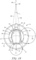
- the indented gripping surfaces 28 and 30 form a V-shape (when viewed elevationally from the top or bottom).
- the V-shape can allow for greater comfort of a user when holding between two fingers.
- the V-shape can follow the contours of the walls forming the gripping surfaces.
- FIG. 2B the V-shape is defined by axes 66 and 68.
- axis 66 defines the indented gripping surface 28 while axis 68 defines indented gripping surface 30.
- the two axes 66 and 68 meet at an apex 69.
- the apex 69 is oriented in the direction of the stem portion 38 (toward the rear of the chestpiece 13).
- the apex can correspond to the angle between fingers of a user in order to provide an ergonomic grip.
- the apex has an angle ⁇ of between 5 and 35 degrees (inclusive), between 5 and 30 degrees (inclusive) between 5 and 25 degrees (inclusive), between 5 and 20 degrees (inclusive), between 5 and 15 degrees (inclusive), between 10 and 15 degrees (inclusive), or preferably, between 12 and 14 degrees (inclusive).
- any portion of the chestpiece 13 can be concavely curved in two directions.
- a portion of the indented gripping surface 30 or top surface can be concavely curved in two directions; from the front toward the back, and from the top toward the bottom.
- the chestpiece 13 is shown as straight along the axes 66 and 68, thus the walls of the indented gripping surface 30 is arcuate along one axis (e.g., axis 68).
- the chestpiece 13 is shown with a protruding edge 31 being partially defined by an axis 57 that is orthogonal or normal to the bottom surface 41.
- a portion of the indented gripping surface 28 (such as the edge 31, which is considered part of the top surface 29 and the indented gripping surface 28 for the purpose of this example) can be arcuate to axis 57 (in addition to axis 66).
- the radius of curvature 63 can be defined based on the outer perimeter 45.
- the radius of curvature 63 of the indented gripping surface 28 can be at least one-fourth, or one-half of a radius of curvature of the chestpiece outer perimeter 45. In at least one embodiment, the radius of curvature 63 can be based on an dimension.
- the radius of curvature 63 of the indented gripping surface 30 (or 28) can be at least 5 mm, at least 7mm, or at least 10 mm.
- the raised center portion 26 can also include a indented gripping surface 74 (which may be referred to as a front indented gripping surface 74.
- the indented gripping surface 74 can defined in part by a front wall 72 (which is also shown on FIG. 2D ) comprising a third concave surface arcuate about axis 19.
- the front wall 72 can extend past the indented gripping surface 74 toward the top surface 29.
- the axis 19 can be normal to the bottom surface 41.
- the indented gripping surface 74 can be similar to indented gripping surfaces 28 and 30.
- the top surface 29 can further include an indented finger portion having a radius of curvature sufficient for a finger.
- the radius of curvature is no greater than 10 mm.
- the front wall 72 can have a radius of curvature no greater than 10 mm.
- the front wall 72 is an intermediate surface that blends the indented portions from the top surface 29 and the indented gripping surface 74.
- the indented gripping surface 74 is defined by axis 70 which is perpendicular to axis 67.
- the indented gripping surface 74 is adjacent to axis 70.
- the indented gripping surface 74 intersects axis 70 at at least two points.
- the axis 70, axis 66, and axis 68 can all form a triangle. In at least one embodiment, the triangle is non-equilateral.
- the indented gripping surface 74 can further have a radius of curvature 21 similar to the radius of curvatures 62, 64 described in FIG. 2D . In at least one embodiment, the radius of curvature 21 is less than the radius of curvature 63.
- any of the indented gripping surfaces can have a roughened texture.
- the indented gripping surfaces have a regularly scored surface.
- the walls of the indented gripping surfaces may be roughened, textured, or have ridges formed thereon.
- the roughened surface may be regular or irregular.
- the walls of the indented gripping surfaces 28 30 or 74 may be scored or impressed with a fish gill or knurled pattern, for example.
- a portion of the top surface 29 can be sloped with respect to said bottom surface 41.
- a portion of the top surface 29 can be closer to the bottom surface 41 at the front (i.e., opposite from the stem portion 38) of the chestpiece 13 than at the rear of the chestpiece 13 (i.e., in the direction of the stem portion 38).
- the top surface of raised center portion 26 preferably is sloped downward from rear to front of chestpiece 13 to form a surface which may be easily formed into the palm of the hand of the user.
- raised center portion 26 is taller at the rear of the chestpiece 13 than at the front of the chestpiece 13.
- the top surface 29 can include a finger recess 54 (as shown in FIG. 2A ).
- the finger recess 54 can be formed from a portion of the top surface 29.
- a finger recess can be located on at least one of the indented gripping surfaces. Finger recesses can provide rest positions for the user's fingers to enhance grip when in alternate positions. Finger recesses can also provide the user with tactile feedback concerning the location of finger hold positions. In at least one embodiment, finger recesses are distinguished from the indented grip portions by the overall width. For example, finger recesses can be dimensioned such that two or more fingers or more than one finger pad of the user will not fit within one finger recess.
- the chestpiece 13 can have a stem portion 38 disposed on a portion of the raised center portion 26.
- the stem portion 38 can be generally parallel (i.e., plus or minus 9 degrees) to the bottom surface 41 meaning that the stem portion 38 which is aligned with axis 81 which is further parallel to the bottom surface 41 (defined by plane 79).
- the stem portion 38 can be askew (meaning aligning with axis 83 and forming greater than a 9 degree angle) relative to the bottom surface 41 (defined by plane 79).
- the stem portion 38 can further include a hole 17 formed therein which opens into the bell cavity 75 such that the stem portion 38 is fluidically coupled to the bell cavity 75 (as shown in FIG. 2E, 2F , and 2G ).
- the chestpiece 13 can be disposable, meaning that the chestpiece 13 is designed to be disposed of after a single use.
- the chestpiece 13 can be made from a polymeric material to facilitate disposal.
- the chestpiece 13 can be made from a metal such as aluminum or steel.
- FIGS. 3A-3D illustrate various holding positions of a stethoscope 100.
- the stethoscope 100 can include the chestpiece 13 of FIGS. 2A-2G .
- the chestpiece 13 is attached to a tubing 102 which further facilitates the holding positions of a user's hand 101.
- FIG. 3A illustrates where an index finger of a hand 101 applies downward force in the direction of a patient at the finger recess on the top surface.
- the finger recess further secures the finger from lateral movements.
- the thumb and middle fingers can further secure the tubing 102 to stabilize the chestpiece 13.
- FIG. 3B illustrates where the lateral portions of two adjacent fingers (e.g., an index finger and middle finger) of a hand 101 apply pressure on the raised center portion and maintain an ergonomic angle.
- two adjacent fingers e.g., an index finger and middle finger
- chestpiece 13 has a raised center portion which is adapted to be grasped by the fingers of the user.
- the protruding edges facilitate the physical stop of the user's fingers from slipping upward.
- the lateral indented gripping surfaces are indented inwards (an in a V-shape) to fit the curve of the user's fingers, the user is provided with tactile feedback concerning the positioning of the chestpiece in the hand. This feedback allows the user to know, understand and adjust, if necessary, the positioning of the chestpiece in the hand without having to visually perceive the chestpiece.
- the lateral indented gripping surfaces can be further adapted to receive two lateral sides of two fingers of the user.
- the lower portion can form a physical stop for the two lateral sides of two fingers from contacting the patient.
- FIG. 3C illustrates where the thumb of the hand 101 contacts one of indented gripping surfaces (lateral), the index finger contacts the front indented gripping surface, and optionally, the ring finger contacts a lateral indented gripping surface.
- FIG. 3D illustrates where the thumb of the hand 101 contacts a first lateral indented gripping surface and the index finger contacts a second lateral indented gripping surface.
- FIGS. 4A-4C illustrate an embodiment of a chestpiece 200.
- the chestpiece 200 can be a pediatric chestpiece 200.
- the chestpiece 200 can have a raised center portion 226 similar to raised center portion 26 described in FIGS. 2A-2G herein.
- the raised center portion 226 can have a stem portion 238 disposed thereon.
- the chestpiece 200 can have an outer perimeter 243.
- the outer perimeter 243 can be an elliptical shape, preferably a circle.
- the raised center portion 226 can have a top surface 229.
- the top surface 229 can be defined by an elliptical shape 216 having a major radius of curvature 219 and a minor radius of curvature 217.
- An aspect of the chestpiece 200 is that the ratio of radius 220 of the outer perimeter 243 to the radius of curvature (in the case of an ellipse, measured from the minor radius 217) of the top surface 229 is no greater than 2.5, no greater than 2.3, no greater than 2.1, or no greater than 2.0.
- the ratio of the radius 220 to the radius 217 of the chestpiece 200 can be less than that of the comparable ratio of chestpiece 13.
- chestpiece 13 of FIG. 1 can have a ratio of between 3 and 2.4 (inclusive), or more preferably, between 2.5 and 2.7 (inclusive).
- the chestpiece 200 can also have a front indented gripping surface 274 similar to indented surface 74 discussed in FIGS. 2A-2G herein.
- the front indented surface 274 can be arcuate to an ellipse 215.
- the ellipse 215 can have a major radius 213 and a minor radius 214. Dimensions of the major radius and minor radius of the ellipse can be sufficient to conform to a finger of a user.
- the major radius can be between 5 to 15 mm (inclusive), or preferably, between 7 to 10 mm (inclusive) and the minor radius can be between 1 to 6 mm (inclusive) or preferably, between 2 mm to 4 mm (inclusive).
- the ellipse 215 shape can be parallel to the bottom surface 41. In at least one embodiment, the ellipse 215 is at least one portion of an elliptical prism wherein portions of the front indented gripping surface 274 are arcuate about one or more ellipses of the elliptical prism.
- the chestpiece 200 can have one or more lateral indented gripping surfaces, e.g., surface 228 which are similar to indented gripping surface 28 discussed herein.
- the indented gripping surface 228 can be defined by an ellipse 201 having a major radius 203 and a minor radius 202.
- the major radius 203 of such an ellipse can be oriented orthogonal to a plane formed by a bottom surface 241 and the minor radius can be oriented parallel to the plane formed by the bottom surface 241. Dimensions of the major radius and minor radius of the ellipse can be sufficient to conform to a finger of a user.
- the major radius can be between 5 to 9 mm (inclusive), or preferably, between 6 to 8 mm (inclusive) and the minor radius can be between 1 to 5 mm (inclusive) or preferably, between 3 mm to 4 mm (inclusive).
- the chestpiece 200 can be single-patient use.
- a method can be performed that includes contacting at least the chestpiece described herein with a patient to monitor for the auscultatory sounds. Before ever contacting the chestpiece with a second patient, the chestpiece is disposed. In at least one embodiment, disposing of the chestpiece means incineration or throwing the chestpiece in the garbage. A second chestpiece may be used with the second patient.
Landscapes
- Health & Medical Sciences (AREA)
- Life Sciences & Earth Sciences (AREA)
- Heart & Thoracic Surgery (AREA)
- Acoustics & Sound (AREA)
- Engineering & Computer Science (AREA)
- Biomedical Technology (AREA)
- Physics & Mathematics (AREA)
- Medical Informatics (AREA)
- Molecular Biology (AREA)
- Surgery (AREA)
- Animal Behavior & Ethology (AREA)
- General Health & Medical Sciences (AREA)
- Public Health (AREA)
- Veterinary Medicine (AREA)
- Dental Tools And Instruments Or Auxiliary Dental Instruments (AREA)
Description
- Stethoscopes have long been used by physicians to monitor auscultatory sounds. Typically, stethoscopes have been comprised of a head or chestpiece, a sound transmission mechanism and a headset assembly. The chestpiece is adapted to be placed against the skin of a patient for gathering auscultatory sounds. The sound transmission mechanism transmits the gathered sound to the earpiece of the headset assembly where the physician may monitor the sound.
- Traditionally, stethoscopes have been designed primarily to optimize acoustic performance for the user and, secondarily, to provide an attractive design/color for personal use. Double-sided stethoscopes have a large acoustic sensor element on both the top and bottom surface of the "chestpiece" and forces the user to grip the chestpiece around these elements. Single-sided stethoscopes have a single acoustic element on the bottom surface and a top surface for the user to hold the chestpiece. Prior art document
US 2010/155173 discloses an ergonomic chestpiece for a stethoscope according to the preamble of claim 1. - Single-sided stethoscopes can often look "aesthetically pleasing" and have "apparent" grip features, but they may be suboptimal for holding the chestpiece, do not conform to the human hand anatomy, provide only limited grip positions, and do not necessarily allow the user to transition seamlessly between grip positions.
- The invention, as defined in claim 1, relates to an ergonomic chestpiece for a stethoscope adapted to receive auscultatory sounds from a patient, comprising a bottom surface which is generally planar and adapted to be placed near the patient for receiving auscultatory sounds. The chestpiece includes a raised center portion defining first and second lateral indented gripping surfaces, the raised center portion having a top surface opposite the bottom surface. The chestpiece includes a stem portion extending distally from the raised center portion. The first lateral indented gripping surface is defined by a first wall comprising a first concave surface arcuate about a first axis and the second lateral indented gripping surface is defined by a second wall comprising a second concave surface arcuate about a second axis. The first axis and the second axis form a V-shape comprising an apex oriented in a direction of the stem portion. The first and second lateral indented gripping surfaces each comprise a protruding edge on the top surface, wherein a horizontal distance of the protruding edge relative to a median-most point of its respective concave surface is from 1 to 4mm measured along a plane parallel to a plane formed from the bottom surface. The chestpiece has a uniform wall thickness, and the raised centre portion is hollow. Claims 2 - 14 define preferred embodiments of the ergonomic chestpiece. Claim 15 relates in essence to a method of using the claimed chestpiece.
-
-
FIG. 1 is a top plan view illustrating a stethoscope incorporating the chestpiece according to one embodiment of the present disclosure. -
FIG. 2A is a perspective view of an illustrative embodiment of the chestpiece, according to various aspects of the present disclosure. -
FIG. 2B is a top view of the chestpiece ofFIG. 2A , according to various aspects of the present disclosure. -
FIG. 2C is a side view of the chestpiece ofFIGS. 2A-2B , according to various aspects of the present disclosure. -
FIG. 2D is a front view of the chestpiece ofFIGS. 2A-2C , according to various aspects of the present disclosure. -
FIG. 2E is a rear view of the chestpiece ofFIGS. 2A-2D , according to various aspects of the present disclosure. -
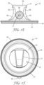
FIG. 2F is a bottom view of the chestpiece ofFIGS. 2A-2E , according to various aspects of the present disclosure. -
FIG. 2G is a bottom perspective view of the chestpiece ofFIGS. 2A-2F , according to various aspects of the present disclosure. -
FIGS. 3A-3D illustrate various finger hold positions of the chestpiece ofFIGS. 2A-2G , according to various aspects of the present disclosure. -
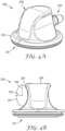
FIG. 4A is a perspective view of an illustrative embodiment of the chestpiece, according to various aspects of the present disclosure. -
FIG. 4B is a front view of an illustrative embodiment of the chestpiece ofFIG. 4A , according to various aspects of the present disclosure. -
FIG. 4C is a top elevational view of an illustrative embodiment of the chestpiece ofFIGS. 4A-4B , according to various aspects of the present disclosure. - Aspects of the present disclosure relate to a chestpiece having one or more ergonomic features. The ergonomic features are configured to fit the way that a human hand grips objects and can allow a user to comfortably grip and transition between different handholds. The user does not actively grip the device, and can relax the hand muscles which can provide an intuitive "feel," reduce fatigue, and potential noise from muscle twitch, movement, or tremor from the user. The
stethoscope 10 illustrated inFIG. 1 includes achestpiece 13, or stethoscope head, aheadset 14 and a connectingtubing 16. Theheadset 14 has twoeartips Tubing couple eartips tubing 16, which in turn is coupled tochestpiece 13. - The sound transmission system of
stethoscope 10 may be acoustic as is known in the art. However, it is also contemplated that the sound transmission system ofstethoscope 10 could also be electronic. Thechestpiece 13 can couple to the connectingtubing 16 via astem portion 38 that inserts into an opening formed in the connectingtubing 16. The connectingtubing 16 can surround thestem portion 38 and form a secure connection. In at least one embodiment, thestem portion 38 can be releasably attached from the connectingtubing 16. - The
chestpiece 13 can also have adiaphragm 40 removably attached. Thediaphragm 40 can be diaphragms such as those commercially available under the trade designation Littmann from 3M (St. Paul, MN). The diaphragm can transmit auscultatory vibrations from the skin of a patient and, optionally, through a layer of clothing. - A kit may be formed that includes any component of the
stethoscope 10. For example, thechestpiece 13,diaphragm 40, aheadset 14, a connectingtubing 16, or combinations thereof can be included in the kit. The kit can also include thestethoscope 10 and any corresponding packaging for thestethoscope 10. -
FIGS. 2A-2G illustrate an embodiment of achestpiece 13 shown inFIG. 1 . Thechestpiece 13 can generally be adapted to fit an adult patient. - In
FIG. 2A , the (ergonomic)chestpiece 13 can be adapted to be placed near the source of auscultatory sound, or, in a preferred embodiment, to contact the skin of the patient. For example, thechestpiece 13 can have a bottom surface 41 (discussed further herein) that can be adapted to be proximate the skin of a patient. - The
chestpiece 13 can have abottom surface 41 that is an elliptical shape. As used herein, the term elliptical shape can refer to a shape having elliptical properties. For example, an elliptical shape can refer to an ellipse, an elliptical prism, a circle, a sphere, or a cylinder. An elliptical prism can comprise one or more ellipses. In at least one embodiment, thebottom surface 41 is circular. Thebottom surface 41 is configured to contact a diaphragm (which can contact the skin of the patient). In some embodiments, thebottom surface 41 is configured to secure a removable diaphragm. - The
chestpiece 13 can further can have anouter perimeter 45 which is also shown in other figures herein (e.g.,FIG. 2F ). Theouter perimeter 45 is an edge of thechestpiece 13 and may be different than thebottom surface 41. In at least one embodiment, theouter perimeter 45 is established from alower portion 39 of thechestpiece 13 and is generally established within the same plane. In at least one embodiment, theouter perimeter 45 can be an oval. Theouter perimeter 45 can also be of various dimensions relative to a raised center portion 26 (described herein). For example, theouter perimeter 45 can be at least 1.5 times the diameter of the raisedcenter portion 26. In another example, (e.g., a pediatric embodiment described inFIG. 4 ) theouter perimeter 45 is less than 1.5 times the diameter of the raisedcenter portion 26. - Turning to
FIG. 2F , thebottom surface 41 of an ergonomic chestpiece of the present invention is generally planar. As used herein, the term "generally" or "about" can mean plus or minus 5% variance. For example, a generally planar (i.e., 180 degrees)bottom surface 41 can mean plus or minus 9 degrees. Thebottom surface 41 can be adapted to mate with a diaphragm (e.g., 40 inFIG. 1 ) which contacts the patient. Thebottom surface 41 can include arim portion 43 that is configured to mate with or removably secure the diaphragm. As shown, therim portion 43 can include a lip that is configured to removably secure the diaphragm (such as 40 inFIG. 1 ). Therim portion 43 can form a diaphragm opening that can lead into thebell cavity 75 of thechestpiece 13. Thebell cavity 75 can be formed from the diaphragm opening formed from therim portion 43, theinterior 73 of a lower portion 39 (shown inFIG. 2A ) , and the interior 71 of a raised center portion 73 (described herein). - Turning to
FIG. 2A , thelower portion 39 of the bell has anupper surface 27. Theupper surface 27 is opposite from thebottom surface 41 and a portion of theupper surface 27 can form bell cavity 75 (as shown inFIG. 2F ) with a portion of the bell (e.g., an upper surface). - The
chestpiece 13 can be oriented alongaxes axis 67 can be the median axis andaxis 65 can be a z-axis or a vertical axis. The raisedcenter portion 26 can extend distally in the direction ofaxis 65 and thestem portion 38 can extend distally in the direction ofaxis 67. - The
chestpiece 13 of the present invention has a raisedcenter portion 26 which has the ergonomic features discussed herein. The raisedcenter portion 26 has at least two indented gripping surfaces or even at least three indented gripping surfaces. The indented gripping surfaces of the raisedcenter portion 26 are adapted to easily, securely and comfortably engage the gripping appendages (as shown herein) of the user. - In
FIG. 2D , indented grippingsurfaces gripping surfaces gripping surfaces chestpiece 13. In at least one embodiment, the indentedgripping surfaces chestpiece 13 to create an indented impression in the indentedgripping surfaces - For example, the indented gripping
surface 30 can be defined by a wall comprising a second concave surface arcuate aboutaxis 68. In at least one embodiment, theaxis 68 is generally parallel to the bottom surface 41 (which may be defined by the plane 79). In at least one embodiment, theaxis 68 can form an angle of no greater than 15 degrees with respect to the bottom surface 41 (e.g., plane 79) or, in other embodiments, relative toaxis 66. The indentedgripping surface 30 can have a radius of curvature defined by 64. In at least one embodiment, the radius ofcurvature 64 is at least 6 mm, at least 7 mm, at least 8 mm, at least 9 mm, at least 10 mm, or even at least 11 mm. In at least one embodiment, the radius ofcurvature 64 can be no greater than 20 mm, no greater than 18 mm, or no greater than 15 mm. - In at least one embodiment, at least one of the indented
gripping surfaces gripping surface 30 can be arcuate about the elliptical prism (i.e., a notional surface of the elliptical prism) or one or more ellipses defining the elliptical prism. - Similarly, the indented gripping
surface 28 can be defined by a wall comprising a first concave surface arcuate aboutaxis 66. In at least one embodiment, the indented grippingsurface 28 can have a radius ofcurvature 62 having similar or the same dimensions of radius ofcurvature 64 described herein. In at least one embodiment, the indented grippingsurface 28 can have a radius ofcurvature 62 that is different than radius ofcurvature 64. For example, the radius ofcurvature 62 can be 10 mm while radius ofcurvature 64 is 9 mm to accommodate finger holds between the middle and index fingers of the user. - Although depicted as having a circular radius of curvature, the dimensions of the lateral indented gripping
surfaces FIGS. 4A-4C ).
In at least one embodiment, the indentedgripping surfaces - According to the invention, the indented
gripping surfaces top surface 29 therein opposite thebottom surface 41. Thetop surface 29 is the topmost surface of the raisedcenter portion 26. Thetop surface 29 differs from theupper surface 27 in that thetop surface 29 can have a greater height relative to thebottom surface 41. - The
top surface 29 has a protrudingedge 31 and 33 (shown inFIGS. 2A ,2E ) formed therein. The protruding edges 31 and 33 overhang off the intended grippingsurfaces gripping surfaces - In at least one embodiment, the indented impressions of the lateral recesses formed into raised
center portion 26 allow indentedgripping surfaces edges gripping surfaces - According to the invention, the protruding edges 31 and 33 can have a
horizontal distance 11. Thehorizontal distance 11 of protrudingedge 31 can be measured betweenaxis 61 that contacts the distal-most point of thetop surface 29 and themedian-most point 12. Thehorizontal distance 11 of the protrudingedge 31 can be measured relative to themedian-most point 12 of the concave surface measured along a plane parallel to aplane 79. In at least one embodiment, thehorizontal distance 11 is between 1 and 4 mm (inclusive), even more preferably, thehorizontal distance 11 is between 2 and 3 mm (inclusive). - The
chestpiece 13 can have aparticular height 59. In at least one embodiment, theheight 59 can be defined from a portion of thetop surface 29 to a portion of the bottom surface 41 (preferably within the same plane). For example, theheight 59 can be measured along a median plane (e.g., formed byaxis FIG. 2A ) of thechestpiece 13. While many heights are possible, thepreferred height 59 can be from 15 mm to 30 mm (inclusive), 15 mm to 25 mm (inclusive), 20 mm to 25 mm (inclusive), or 20 mm to 22 mm (inclusive). - The indented
gripping surfaces FIG. 2B , according to the invention the V-shape is defined byaxes axis 66 defines the indented grippingsurface 28 whileaxis 68 defines indented grippingsurface 30. The twoaxes - In at least one embodiment, any portion of the
chestpiece 13 can be concavely curved in two directions. In at least one embodiment, a portion of the indented grippingsurface 30 or top surface can be concavely curved in two directions; from the front toward the back, and from the top toward the bottom. - The
chestpiece 13 is shown as straight along theaxes surface 30 is arcuate along one axis (e.g., axis 68). Thechestpiece 13 is shown with a protrudingedge 31 being partially defined by anaxis 57 that is orthogonal or normal to thebottom surface 41. A portion of the indented gripping surface 28 (such as theedge 31, which is considered part of thetop surface 29 and the indented grippingsurface 28 for the purpose of this example) can be arcuate to axis 57 (in addition to axis 66). In at least one embodiment, the radius ofcurvature 63 can be defined based on theouter perimeter 45. For example, the radius ofcurvature 63 of the indented grippingsurface 28 can be at least one-fourth, or one-half of a radius of curvature of the chestpieceouter perimeter 45. In at least one embodiment, the radius ofcurvature 63 can be based on an dimension. For example, the radius ofcurvature 63 of the indented gripping surface 30 (or 28) can be at least 5 mm, at least 7mm, or at least 10 mm. - The raised
center portion 26 can also include a indented gripping surface 74 (which may be referred to as a front indented grippingsurface 74. The indentedgripping surface 74 can defined in part by a front wall 72 (which is also shown onFIG. 2D ) comprising a third concave surface arcuate aboutaxis 19. In at least one embodiment, thefront wall 72 can extend past the indented grippingsurface 74 toward thetop surface 29. Theaxis 19 can be normal to thebottom surface 41. The indentedgripping surface 74 can be similar to indentedgripping surfaces - Turning to
FIG. 2A , thetop surface 29 can further include an indented finger portion having a radius of curvature sufficient for a finger. In at least one embodiment, the radius of curvature is no greater than 10 mm. Thefront wall 72 can have a radius of curvature no greater than 10 mm. In at least one embodiment, thefront wall 72 is an intermediate surface that blends the indented portions from thetop surface 29 and the indented grippingsurface 74. - Returning to
FIG. 2B , in at least one embodiment, the indented grippingsurface 74 is defined byaxis 70 which is perpendicular toaxis 67. The indentedgripping surface 74 is adjacent toaxis 70. In at least one embodiment, the indented grippingsurface 74 intersectsaxis 70 at at least two points. Theaxis 70,axis 66, andaxis 68 can all form a triangle. In at least one embodiment, the triangle is non-equilateral. - The indented
gripping surface 74 can further have a radius ofcurvature 21 similar to the radius ofcurvatures FIG. 2D . In at least one embodiment, the radius ofcurvature 21 is less than the radius ofcurvature 63. - In at least one embodiment, any of the indented gripping surfaces (e.g., 28, 30 or 74) can have a roughened texture. The indented gripping surfaces have a regularly scored surface. For example, to further increase the security of the indented
gripping surfaces gripping surfaces 28 30 or 74 may be scored or impressed with a fish gill or knurled pattern, for example. By roughening or texturing the walls of the indentedgripping surfaces 28 30 or 74, the security of the chestpiece in the hand is improved. In addition, the ability of the user to adequately grip the chestpiece is improved, thus reducing the likelihood of thechestpiece 13 slipping out of the user's grip and allowing the user to reduce/minimize effort needed to hold device. - Turning to
FIG. 2C , a portion of thetop surface 29 can be sloped with respect to saidbottom surface 41. For example, a portion of thetop surface 29 can be closer to thebottom surface 41 at the front (i.e., opposite from the stem portion 38) of thechestpiece 13 than at the rear of the chestpiece 13 (i.e., in the direction of the stem portion 38). In at least one embodiment, the top surface of raisedcenter portion 26 preferably is sloped downward from rear to front ofchestpiece 13 to form a surface which may be easily formed into the palm of the hand of the user. Thus, raisedcenter portion 26 is taller at the rear of thechestpiece 13 than at the front of thechestpiece 13. In at least one embodiment, thetop surface 29 can include a finger recess 54 (as shown inFIG. 2A ). Thefinger recess 54 can be formed from a portion of thetop surface 29. - In at least one embodiment, a finger recess can be located on at least one of the indented gripping surfaces. Finger recesses can provide rest positions for the user's fingers to enhance grip when in alternate positions. Finger recesses can also provide the user with tactile feedback concerning the location of finger hold positions. In at least one embodiment, finger recesses are distinguished from the indented grip portions by the overall width. For example, finger recesses can be dimensioned such that two or more fingers or more than one finger pad of the user will not fit within one finger recess.
- The
chestpiece 13 can have astem portion 38 disposed on a portion of the raisedcenter portion 26. Thestem portion 38 can be generally parallel (i.e., plus or minus 9 degrees) to thebottom surface 41 meaning that thestem portion 38 which is aligned withaxis 81 which is further parallel to the bottom surface 41 (defined by plane 79). In at least one embodiment, thestem portion 38 can be askew (meaning aligning withaxis 83 and forming greater than a 9 degree angle) relative to the bottom surface 41 (defined by plane 79). Thestem portion 38 can further include ahole 17 formed therein which opens into thebell cavity 75 such that thestem portion 38 is fluidically coupled to the bell cavity 75 (as shown inFIG. 2E, 2F , and2G ). - In at least one embodiment, the
chestpiece 13 can be disposable, meaning that thechestpiece 13 is designed to be disposed of after a single use. Thechestpiece 13 can be made from a polymeric material to facilitate disposal. In at least one embodiment, thechestpiece 13 can be made from a metal such as aluminum or steel. -
FIGS. 3A-3D illustrate various holding positions of astethoscope 100. Thestethoscope 100 can include thechestpiece 13 ofFIGS. 2A-2G . Thechestpiece 13 is attached to atubing 102 which further facilitates the holding positions of a user'shand 101. -
FIG. 3A illustrates where an index finger of ahand 101 applies downward force in the direction of a patient at the finger recess on the top surface. The finger recess further secures the finger from lateral movements. The thumb and middle fingers can further secure thetubing 102 to stabilize thechestpiece 13. -
FIG. 3B illustrates where the lateral portions of two adjacent fingers (e.g., an index finger and middle finger) of ahand 101 apply pressure on the raised center portion and maintain an ergonomic angle. - For example,
chestpiece 13 has a raised center portion which is adapted to be grasped by the fingers of the user. The protruding edges facilitate the physical stop of the user's fingers from slipping upward. In addition, because the lateral indented gripping surfaces are indented inwards (an in a V-shape) to fit the curve of the user's fingers, the user is provided with tactile feedback concerning the positioning of the chestpiece in the hand. This feedback allows the user to know, understand and adjust, if necessary, the positioning of the chestpiece in the hand without having to visually perceive the chestpiece. - The lateral indented gripping surfaces can be further adapted to receive two lateral sides of two fingers of the user. For instance, the lower portion can form a physical stop for the two lateral sides of two fingers from contacting the patient.
-
FIG. 3C illustrates where the thumb of thehand 101 contacts one of indented gripping surfaces (lateral), the index finger contacts the front indented gripping surface, and optionally, the ring finger contacts a lateral indented gripping surface. -
FIG. 3D illustrates where the thumb of thehand 101 contacts a first lateral indented gripping surface and the index finger contacts a second lateral indented gripping surface. -
FIGS. 4A-4C illustrate an embodiment of achestpiece 200. Thechestpiece 200 can be apediatric chestpiece 200. Thechestpiece 200 can have a raisedcenter portion 226 similar to raisedcenter portion 26 described inFIGS. 2A-2G herein. The raisedcenter portion 226 can have astem portion 238 disposed thereon. Thechestpiece 200 can have anouter perimeter 243. In at least one embodiment, theouter perimeter 243 can be an elliptical shape, preferably a circle. The raisedcenter portion 226 can have atop surface 229. - The
top surface 229 can be defined by anelliptical shape 216 having a major radius ofcurvature 219 and a minor radius ofcurvature 217. An aspect of thechestpiece 200 is that the ratio ofradius 220 of theouter perimeter 243 to the radius of curvature (in the case of an ellipse, measured from the minor radius 217) of thetop surface 229 is no greater than 2.5, no greater than 2.3, no greater than 2.1, or no greater than 2.0. The ratio of theradius 220 to theradius 217 of thechestpiece 200 can be less than that of the comparable ratio ofchestpiece 13. For example, chestpiece 13 ofFIG. 1 can have a ratio of between 3 and 2.4 (inclusive), or more preferably, between 2.5 and 2.7 (inclusive). - The
chestpiece 200 can also have a front indentedgripping surface 274 similar toindented surface 74 discussed inFIGS. 2A-2G herein. The frontindented surface 274 can be arcuate to anellipse 215. Theellipse 215 can have amajor radius 213 and aminor radius 214. Dimensions of the major radius and minor radius of the ellipse can be sufficient to conform to a finger of a user. For example, the major radius can be between 5 to 15 mm (inclusive), or preferably, between 7 to 10 mm (inclusive) and the minor radius can be between 1 to 6 mm (inclusive) or preferably, between 2 mm to 4 mm (inclusive). In at least one embodiment, theellipse 215 shape can be parallel to thebottom surface 41. In at least one embodiment, theellipse 215 is at least one portion of an elliptical prism wherein portions of the front indented grippingsurface 274 are arcuate about one or more ellipses of the elliptical prism. - The
chestpiece 200 can have one or more lateral indented gripping surfaces, e.g.,surface 228 which are similar to indented grippingsurface 28 discussed herein. In at least one embodiment, the indentedgripping surface 228 can be defined by anellipse 201 having amajor radius 203 and aminor radius 202. In at least one embodiment, themajor radius 203 of such an ellipse can be oriented orthogonal to a plane formed by abottom surface 241 and the minor radius can be oriented parallel to the plane formed by thebottom surface 241. Dimensions of the major radius and minor radius of the ellipse can be sufficient to conform to a finger of a user. For example, the major radius can be between 5 to 9 mm (inclusive), or preferably, between 6 to 8 mm (inclusive) and the minor radius can be between 1 to 5 mm (inclusive) or preferably, between 3 mm to 4 mm (inclusive). - In at least one embodiment, the
chestpiece 200 can be single-patient use. For example, a method can be performed that includes contacting at least the chestpiece described herein with a patient to monitor for the auscultatory sounds. Before ever contacting the chestpiece with a second patient, the chestpiece is disposed. In at least one embodiment, disposing of the chestpiece means incineration or throwing the chestpiece in the garbage. A second chestpiece may be used with the second patient.
Claims (15)
- An ergonomic chestpiece (13, 200) for a stethoscope (10, 100) adapted to receive auscultatory sounds from a patient, comprising:a bottom surface (41, 241) which is generally planar adapted to be placed near the patient for receiving auscultatory sounds;a raised center portion (26, 226) defining first (28, 228) and second (30, 230) lateral indented gripping surfaces, the raised center portion having a top surface (29, 229) opposite the bottom surface; anda stem portion (38, 238) extending distally from the raised center portion;wherein the first lateral indented gripping surface is defined by a first wall comprising a first concave surface arcuate about a first axis (66),wherein the second lateral indented gripping surface is defined by a second wall comprising a second concave surface arcuate about a second axis (68),wherein the first axis and the second axis form a V-shape comprising an apex (69) oriented in a direction of the stem portion;characterised in that:the first and second lateral indented gripping surfaces each comprise a protruding edge (31, 33) on the top surface, wherein a horizontal distance (11) of the protruding edge relative to a median-most point (12) of its respective concave surface is from 1 to 4 mm (inclusive) measured along a plane parallel to a plane formed from the bottom surface;wherein the chestpiece has a uniform wall thickness and the raised center portion is hollow.
- The ergonomic chestpiece of claim 1, wherein the stem portion is generally parallel to the bottom surface.
- The ergonomic chestpiece of claim 1 or 2, wherein the V-shape comprises an angle of between 5 and 35 degrees.
- The ergonomic chestpiece of any of claims 1 to 3, wherein a concave surface is continuous along an entire wall.
- The ergonomic chestpiece of any of claims 1 to 4, wherein the first or second concave surface has a radius of curvature of no greater than 20 mm.
- The ergonomic chestpiece of any of claims 1 to 5, wherein the raised center portion further comprises a front indented gripping surface (74, 274) defined by a front wall, wherein a portion of the front wall comprises a third concave surface arcuate about a third axis (19), wherein the third axis is parallel to a plane formed by the bottom surface.
- The ergonomic chestpiece of claim 6, wherein the third axis, the second axis, and the first axis form a triangle.
- The ergonomic chestpiece of claim 7, wherein a radius of curvature of the first or second lateral indented gripping portion is at least one-fourth of a radius of curvature of an outer perimeter.
- The ergonomic chestpiece of any of claims 1 to 8, wherein the first concave surface is also arcuate about an elliptical shape, wherein the elliptical shape is an elliptical prism oriented along the first axis, wherein the elliptical prism comprises an ellipse, wherein the ellipse has a minor radius and a major radius, wherein the major radius has dimensions between 5 to 9 mm (inclusive), and the minor radius has dimension between 1 to 5 mm (inclusive).
- The ergonomic chestpiece of any of claims 1 to 9, wherein the top surface is an ellipse and the outer perimeter is circular.
- The ergonomic chestpiece of claim 10, wherein a ratio of a first radius of the outer perimeter of the chestpiece to a second radius of the top surface is at least 1:9, wherein the second radius is a minor radius.
- The ergonomic chestpiece of any of claims 6 to 11, wherein the third concave surface is arcuate about an elliptical prism oriented along the third axis.
- The ergonomic chestpiece of claim 12, wherein the elliptical prism comprises an ellipse and the major radius has dimensions between 5 to 9 mm (inclusive), and the minor radius has dimension between 1 to 5 mm (inclusive).
- A stethoscope (10, 100) comprising:the ergonomic chestpiece (13, 200) of any of claims 1 to 13;a diaphragm (40) removably attached to the ergonomic chestpiece;a headset (14); andtubing (16, 102) that couples the headset to the ergonomic chestpiece.
- A method comprising:contacting a portion of the ergonomic chestpiece or diaphragm thereon of any of claims 1 to 13 with a first patient,disposing of the ergonomic chestpiece without contacting the ergonomic chestpiece to a second patient.
Applications Claiming Priority (2)
| Application Number | Priority Date | Filing Date | Title |
|---|---|---|---|
| US201762560470P | 2017-09-19 | 2017-09-19 | |
| PCT/IB2018/056130 WO2019058191A1 (en) | 2017-09-19 | 2018-08-15 | Ergonomic chestpiece |
Publications (3)
| Publication Number | Publication Date |
|---|---|
| EP3684259A1 EP3684259A1 (en) | 2020-07-29 |
| EP3684259A4 EP3684259A4 (en) | 2021-06-02 |
| EP3684259B1 true EP3684259B1 (en) | 2025-04-02 |
Family
ID=65811088
Family Applications (1)
| Application Number | Title | Priority Date | Filing Date |
|---|---|---|---|
| EP18858989.9A Active EP3684259B1 (en) | 2017-09-19 | 2018-08-15 | Ergonomic chestpiece |
Country Status (3)
| Country | Link |
|---|---|
| US (1) | US11369336B2 (en) |
| EP (1) | EP3684259B1 (en) |
| WO (1) | WO2019058191A1 (en) |
Citations (2)
| Publication number | Priority date | Publication date | Assignee | Title |
|---|---|---|---|---|
| EP0094183A2 (en) * | 1982-05-12 | 1983-11-16 | Minnesota Mining And Manufacturing Company | Tunable stethoscope |
| US20140254814A1 (en) * | 2013-03-06 | 2014-09-11 | David A. Van Alstine | Electronic Stethoscope |
Family Cites Families (65)
| Publication number | Priority date | Publication date | Assignee | Title |
|---|---|---|---|---|
| US2513827A (en) | 1950-07-04 | Stethoscope with valved sound | ||
| US2858898A (en) | 1952-08-02 | 1958-11-04 | Cinquini | |
| US3339667A (en) * | 1966-08-02 | 1967-09-05 | Propper Mfg Company Inc | Stethoscope |
| USD256951S (en) | 1978-01-26 | 1980-09-16 | Allen Derek R | Dual stethoscope microphone |
| USD277890S (en) | 1982-05-12 | 1985-03-05 | Minnesota Mining And Manufacturing Company | Stethoscope head |
| DE8504877U1 (en) | 1985-02-21 | 1986-02-06 | Wilhelm Haselmeier Gmbh & Co, 7000 Stuttgart | Double tube stethoscope |
| US5111904A (en) | 1989-06-02 | 1992-05-12 | Minnesota Mining And Manufacturing Company | Molded article having elastomeric mold member used therewith |
| USD323394S (en) | 1989-07-28 | 1992-01-21 | Minnesota Mining And Manufacturing Company | Stethoscope chestpiece |
| DE4029122A1 (en) | 1990-09-13 | 1992-03-19 | Richard Kallmeyer Nachf | Stethoscope with breast piece - has at least one chamber limited on one external side by membrane, and two auscultatory tubes |
| BR9006529A (en) | 1990-12-17 | 1992-08-11 | Antonio Gebara Jose | PORTABLE ELECTRONIC STETHOSCOPE |
| USD337381S (en) | 1991-02-20 | 1993-07-13 | Minnesota Mining And Manufacturing Company | Ergonometric stethoscope chestpiece |
| US5204500A (en) * | 1991-02-20 | 1993-04-20 | Minnesota Mining And Manufacturing Company | Ergonometric stethoscope chestpiece |
| USD338269S (en) | 1992-11-06 | 1993-08-10 | Minnesota Mining And Manufacturing Company | Ergonometric stethoscope chestpiece |
| US5466897A (en) * | 1994-06-08 | 1995-11-14 | Modern Medical Devices | Stethoscope diaphragm dispenser and method |
| FR2722677A1 (en) | 1994-07-25 | 1996-01-26 | Berrehail Mohammed | Equipment for examining physiological sounds for medical purposes |
| USD373824S (en) | 1994-08-03 | 1996-09-17 | Minnesota Mining And Manufacturing Company | Stethoscope chestpiece |
| USD395509S (en) * | 1995-11-14 | 1998-06-23 | Minnesota Mining And Manufacturing Company | Stethoscope chestpiece |
| US6026170A (en) | 1995-11-27 | 2000-02-15 | Minnesota Mining And Manufacturing Company | Electronic stethoscope with idealized bell and idealized diaphragm modes |
| US5663532A (en) | 1995-11-27 | 1997-09-02 | Minnesota Mining And Manufacturing Company | Ergonometric stethoscope chestpiece |
| USD379512S (en) | 1996-01-11 | 1997-05-27 | Minnesota Mining And Manufacturing Company | Ergonometric stethoscope chestpiece |
| US5747752A (en) * | 1997-01-30 | 1998-05-05 | Graham-Field, Inc. | Stethoscope with disposable chestpiece |
| IL120170A0 (en) | 1997-02-06 | 1997-06-10 | Goldenberg Lion | Body sounds observation system |
| USD403065S (en) | 1997-03-03 | 1998-12-22 | Minnesota Mining And Manufacturing Company | Stethoscope component |
| CH691757A5 (en) | 1997-05-13 | 2001-10-15 | Artemio Granzotto | Stethoscope head. |
| GB2327353A (en) | 1997-07-22 | 1999-01-27 | Shieh Woei Kang | A Switch-Frequency Stethoscope |
| USD410285S (en) | 1997-11-06 | 1999-05-25 | Minnesota Mining And Manufacturing Company | Stethoscope chestpiece |
| US6340350B1 (en) | 2000-01-06 | 2002-01-22 | Juanita P. Simms | Transmitter/receiver stethoscope and holder therefor |
| US6520281B1 (en) * | 2000-08-18 | 2003-02-18 | Doctors Research Group | Elastomeric anti-microbial stethoscope diaphragm |
| US20030002685A1 (en) | 2001-06-27 | 2003-01-02 | Werblud Marc S. | Electronic stethoscope |
| US6691821B2 (en) * | 2001-09-07 | 2004-02-17 | 3M Innovative Properties Company | Customizable spilt stem stethoscope and a method for providing same |
| US6725966B2 (en) * | 2002-04-29 | 2004-04-27 | 3M Innovative Properties Company | Stethoscope |
| US6966400B1 (en) | 2002-06-27 | 2005-11-22 | Aaron Rollins | Method and device for utilization of a stethoscope as a neurological diagnostic tool and percussion tool |
| DE10320011A1 (en) | 2003-05-06 | 2004-12-02 | Iouri Charlot | Auscultation and percussion diagnosis unit for physical examination of patient, has sound absorbing unit having acoustic horn internally equipped with percussion device |
| DE20306950U1 (en) | 2003-05-06 | 2003-07-17 | Charlot, Iouri, 19063 Schwerin | Universal diagnostic tool also to be used for auscultatory percussion, comprising integrated percussion device |
| US20060098825A1 (en) * | 2004-11-05 | 2006-05-11 | Katz Hart V | Electronic adaption of acoustical stethoscope |
| WO2006071948A2 (en) | 2004-12-28 | 2006-07-06 | Melder Patrick C | Endoscopic imaging system |
| FR2887430B1 (en) | 2005-06-23 | 2007-08-31 | Olivier Bernard Bassee | WIRELESS STETHOSCOPE WITH PULSE INDICATOR FOR RESPIRATORY FREQUENCY AND TEMPERATURE |
| US9398891B2 (en) | 2005-10-20 | 2016-07-26 | Tiba Medical, Inc. | Multiple communication interface medical examination apparatus, system, and/or method |
| US8092396B2 (en) | 2005-10-20 | 2012-01-10 | Merat Bagha | Electronic auscultation device |
| US8024974B2 (en) | 2005-11-23 | 2011-09-27 | 3M Innovative Properties Company | Cantilevered bioacoustic sensor and method using same |
| US7998091B2 (en) | 2005-11-23 | 2011-08-16 | 3M Innovative Properties Company | Weighted bioacoustic sensor and method of using same |
| WO2007106804A2 (en) | 2006-03-15 | 2007-09-20 | Hill-Rom Services, Inc. | High frequency chest wall oscillation system |
| US7991165B2 (en) * | 2006-10-04 | 2011-08-02 | The United States Of America As Represented By The Secretary Of The Navy | Noise rejecting electronic stethoscope |
| US8594339B2 (en) | 2007-03-23 | 2013-11-26 | 3M Innovative Properties Company | Power management for medical sensing devices employing multiple sensor signal feature detection |
| US7516814B1 (en) | 2007-11-09 | 2009-04-14 | Joseph Berk | Dual-sensor anti-sepsis stethoscope and device |
| US7705325B2 (en) | 2008-02-21 | 2010-04-27 | Mark Vestal | Sterilization device for a stethoscope and associated apparatus |
| US20100155173A1 (en) | 2008-12-22 | 2010-06-24 | Boyd Stacy L | Stethoscope with built-in light |
| CN201409930Y (en) | 2009-06-08 | 2010-02-24 | 程协慧 | handle-type stethoscope |
| US20110048841A1 (en) * | 2009-08-27 | 2011-03-03 | Hasbun William M | Integrated stethoscope and reflex hammer and a method for use |
| JP2012055354A (en) | 2010-09-06 | 2012-03-22 | Univ Of Tsukuba | Diagnostic device |
| CN201759580U (en) | 2010-09-06 | 2011-03-16 | 李传新 | Stethoscope sound head |
| RU122867U1 (en) | 2011-02-02 | 2012-12-20 | Государственное образовательное учреждение высшего профессионального образования "Тульский государственный университет" (ТулГУ) | BINAURAL STETHOSCOPE |
| WO2013156999A1 (en) | 2012-04-19 | 2013-10-24 | Raz Nir | System & method for facilitating remote medical diagnosis and consultation |
| ES1079058Y (en) | 2013-04-08 | 2013-07-25 | Perez Ruben Lopez | WIRELESS ADJUSTMENT SYSTEM |
| US9770307B2 (en) | 2013-06-21 | 2017-09-26 | Jon Krupnick | Cover assembly for a stethoscope and a dispenser kit |
| JP2016538091A (en) | 2013-09-22 | 2016-12-08 | マムセンス・リミテッド | System and method for detecting infant swallowing |
| WO2015105730A1 (en) | 2014-01-07 | 2015-07-16 | Barbier Benjamin Arana | Hand sanitizing dispensing device |
| USD750241S1 (en) | 2014-03-25 | 2016-02-23 | Wuxi Kaishun Medical Device Manufacturing Co., Ltd. | Stethoscope head |
| EP2945084A1 (en) | 2014-05-12 | 2015-11-18 | Electrosalus Biyomedikal Sanayi ve Ticaret Anonim Sirketi | Auscultation data acquisition, communication and evaluation system incorporating mobile facilities |
| CN204192651U (en) | 2014-10-23 | 2015-03-11 | 陈键 | A kind of pediatric auscultation device |
| CN105581810A (en) | 2014-10-23 | 2016-05-18 | 陈键 | Auscultatory device for department of pediatrics |
| US20160287207A1 (en) | 2015-04-02 | 2016-10-06 | Yan Xue | Smart medical examination and communication apparatus |
| USD837979S1 (en) * | 2015-07-31 | 2019-01-08 | Wuxi Kaishun Medical Device Manufacturing Co., Ltd. | Stethoscope head |
| USD840028S1 (en) * | 2016-12-02 | 2019-02-05 | Wuxi Kaishun Medical Device Manufacturing Co., Ltd | Stethoscope head |
| USD858759S1 (en) | 2017-09-19 | 2019-09-03 | 3M Innovative Properties Company | Stethoscope chestpiece |
-
2018
- 2018-08-15 US US16/647,877 patent/US11369336B2/en active Active
- 2018-08-15 WO PCT/IB2018/056130 patent/WO2019058191A1/en not_active Ceased
- 2018-08-15 EP EP18858989.9A patent/EP3684259B1/en active Active
Patent Citations (2)
| Publication number | Priority date | Publication date | Assignee | Title |
|---|---|---|---|---|
| EP0094183A2 (en) * | 1982-05-12 | 1983-11-16 | Minnesota Mining And Manufacturing Company | Tunable stethoscope |
| US20140254814A1 (en) * | 2013-03-06 | 2014-09-11 | David A. Van Alstine | Electronic Stethoscope |
Also Published As
| Publication number | Publication date |
|---|---|
| US11369336B2 (en) | 2022-06-28 |
| EP3684259A1 (en) | 2020-07-29 |
| WO2019058191A1 (en) | 2019-03-28 |
| US20200214660A1 (en) | 2020-07-09 |
| EP3684259A4 (en) | 2021-06-02 |
Similar Documents
| Publication | Publication Date | Title |
|---|---|---|
| EP3047831B1 (en) | Oral cavity function training tool | |
| JP2002512569A (en) | Adaptable pressure writing instrument holder | |
| US11065518B2 (en) | Handle grip control device | |
| EP0957767B1 (en) | Ergonometric stethoscope chestpiece | |
| US10455961B2 (en) | Adaptive handcuff for progressive feeding utensils | |
| JP2020175246A5 (en) | ||
| WO2014069514A1 (en) | Implement for training facial muscle | |
| US11369336B2 (en) | Ergonomic chestpiece | |
| US5520624A (en) | Back support | |
| WO2017179731A1 (en) | Oral cavity function training implement | |
| JP4610921B2 (en) | Kitchen knife | |
| JP4851205B2 (en) | Finger movement aid | |
| JP4789038B2 (en) | Face wear device and band for face wear device | |
| JP6617896B1 (en) | Colposcope | |
| JP7202608B2 (en) | Myofascial release jig | |
| JP3157670U (en) | Drug application equipment | |
| US20210000639A1 (en) | Airflow inhibitor apparatus | |
| JP2003070876A (en) | grip | |
| CN223392489U (en) | Oral retractor set | |
| US20250262474A1 (en) | Grip assist device for athletic training weights and methods related thereto | |
| CN112137870A (en) | Fascia Gun | |
| US12150767B2 (en) | Patch stack-up | |
| CN214105161U (en) | Fascia gun | |
| CN215020778U (en) | A wheelchair table board and wheelchair for rehabilitation training | |
| JP3041340U (en) | Container with finger rest |
Legal Events
| Date | Code | Title | Description |
|---|---|---|---|
| STAA | Information on the status of an ep patent application or granted ep patent |
Free format text: STATUS: THE INTERNATIONAL PUBLICATION HAS BEEN MADE |
|
| PUAI | Public reference made under article 153(3) epc to a published international application that has entered the european phase |
Free format text: ORIGINAL CODE: 0009012 |
|
| STAA | Information on the status of an ep patent application or granted ep patent |
Free format text: STATUS: REQUEST FOR EXAMINATION WAS MADE |
|
| 17P | Request for examination filed |
Effective date: 20200319 |
|
| AK | Designated contracting states |
Kind code of ref document: A1 Designated state(s): AL AT BE BG CH CY CZ DE DK EE ES FI FR GB GR HR HU IE IS IT LI LT LU LV MC MK MT NL NO PL PT RO RS SE SI SK SM TR |
|
| AX | Request for extension of the european patent |
Extension state: BA ME |
|
| DAV | Request for validation of the european patent (deleted) | ||
| DAX | Request for extension of the european patent (deleted) | ||
| A4 | Supplementary search report drawn up and despatched |
Effective date: 20210506 |
|
| RIC1 | Information provided on ipc code assigned before grant |
Ipc: A61B 7/02 20060101AFI20210429BHEP |
|
| STAA | Information on the status of an ep patent application or granted ep patent |
Free format text: STATUS: EXAMINATION IS IN PROGRESS |
|
| 17Q | First examination report despatched |
Effective date: 20220209 |
|
| RAP1 | Party data changed (applicant data changed or rights of an application transferred) |
Owner name: SOLVENTUM INTELLECTUAL PROPERTIES COMPANY |
|
| GRAP | Despatch of communication of intention to grant a patent |
Free format text: ORIGINAL CODE: EPIDOSNIGR1 |
|
| STAA | Information on the status of an ep patent application or granted ep patent |
Free format text: STATUS: GRANT OF PATENT IS INTENDED |
|
| INTG | Intention to grant announced |
Effective date: 20241120 |
|
| GRAS | Grant fee paid |
Free format text: ORIGINAL CODE: EPIDOSNIGR3 |
|
| GRAA | (expected) grant |
Free format text: ORIGINAL CODE: 0009210 |
|
| STAA | Information on the status of an ep patent application or granted ep patent |
Free format text: STATUS: THE PATENT HAS BEEN GRANTED |
|
| AK | Designated contracting states |
Kind code of ref document: B1 Designated state(s): AL AT BE BG CH CY CZ DE DK EE ES FI FR GB GR HR HU IE IS IT LI LT LU LV MC MK MT NL NO PL PT RO RS SE SI SK SM TR |
|
| REG | Reference to a national code |
Ref country code: GB Ref legal event code: FG4D |
|
| REG | Reference to a national code |
Ref country code: CH Ref legal event code: EP |
|
| REG | Reference to a national code |
Ref country code: IE Ref legal event code: FG4D |
|
| REG | Reference to a national code |
Ref country code: DE Ref legal event code: R096 Ref document number: 602018080799 Country of ref document: DE |
|
| REG | Reference to a national code |
Ref country code: NL Ref legal event code: MP Effective date: 20250402 |
|
| PG25 | Lapsed in a contracting state [announced via postgrant information from national office to epo] |
Ref country code: NL Free format text: LAPSE BECAUSE OF FAILURE TO SUBMIT A TRANSLATION OF THE DESCRIPTION OR TO PAY THE FEE WITHIN THE PRESCRIBED TIME-LIMIT Effective date: 20250402 |
|
| REG | Reference to a national code |
Ref country code: AT Ref legal event code: MK05 Ref document number: 1780491 Country of ref document: AT Kind code of ref document: T Effective date: 20250402 |
|
| PG25 | Lapsed in a contracting state [announced via postgrant information from national office to epo] |
Ref country code: PT Free format text: LAPSE BECAUSE OF FAILURE TO SUBMIT A TRANSLATION OF THE DESCRIPTION OR TO PAY THE FEE WITHIN THE PRESCRIBED TIME-LIMIT Effective date: 20250804 Ref country code: ES Free format text: LAPSE BECAUSE OF FAILURE TO SUBMIT A TRANSLATION OF THE DESCRIPTION OR TO PAY THE FEE WITHIN THE PRESCRIBED TIME-LIMIT Effective date: 20250402 Ref country code: FI Free format text: LAPSE BECAUSE OF FAILURE TO SUBMIT A TRANSLATION OF THE DESCRIPTION OR TO PAY THE FEE WITHIN THE PRESCRIBED TIME-LIMIT Effective date: 20250402 |
|
| PGFP | Annual fee paid to national office [announced via postgrant information from national office to epo] |
Ref country code: DE Payment date: 20250724 Year of fee payment: 8 |
|
| REG | Reference to a national code |
Ref country code: LT Ref legal event code: MG9D |
|
| PG25 | Lapsed in a contracting state [announced via postgrant information from national office to epo] |
Ref country code: NO Free format text: LAPSE BECAUSE OF FAILURE TO SUBMIT A TRANSLATION OF THE DESCRIPTION OR TO PAY THE FEE WITHIN THE PRESCRIBED TIME-LIMIT Effective date: 20250702 Ref country code: GR Free format text: LAPSE BECAUSE OF FAILURE TO SUBMIT A TRANSLATION OF THE DESCRIPTION OR TO PAY THE FEE WITHIN THE PRESCRIBED TIME-LIMIT Effective date: 20250703 |
|
| PG25 | Lapsed in a contracting state [announced via postgrant information from national office to epo] |
Ref country code: PL Free format text: LAPSE BECAUSE OF FAILURE TO SUBMIT A TRANSLATION OF THE DESCRIPTION OR TO PAY THE FEE WITHIN THE PRESCRIBED TIME-LIMIT Effective date: 20250402 |
|
| PG25 | Lapsed in a contracting state [announced via postgrant information from national office to epo] |
Ref country code: BG Free format text: LAPSE BECAUSE OF FAILURE TO SUBMIT A TRANSLATION OF THE DESCRIPTION OR TO PAY THE FEE WITHIN THE PRESCRIBED TIME-LIMIT Effective date: 20250402 |
|
| PG25 | Lapsed in a contracting state [announced via postgrant information from national office to epo] |
Ref country code: HR Free format text: LAPSE BECAUSE OF FAILURE TO SUBMIT A TRANSLATION OF THE DESCRIPTION OR TO PAY THE FEE WITHIN THE PRESCRIBED TIME-LIMIT Effective date: 20250402 |
|
| PG25 | Lapsed in a contracting state [announced via postgrant information from national office to epo] |
Ref country code: AT Free format text: LAPSE BECAUSE OF FAILURE TO SUBMIT A TRANSLATION OF THE DESCRIPTION OR TO PAY THE FEE WITHIN THE PRESCRIBED TIME-LIMIT Effective date: 20250402 |
|
| PG25 | Lapsed in a contracting state [announced via postgrant information from national office to epo] |
Ref country code: RS Free format text: LAPSE BECAUSE OF FAILURE TO SUBMIT A TRANSLATION OF THE DESCRIPTION OR TO PAY THE FEE WITHIN THE PRESCRIBED TIME-LIMIT Effective date: 20250702 |
|
| PG25 | Lapsed in a contracting state [announced via postgrant information from national office to epo] |
Ref country code: IS Free format text: LAPSE BECAUSE OF FAILURE TO SUBMIT A TRANSLATION OF THE DESCRIPTION OR TO PAY THE FEE WITHIN THE PRESCRIBED TIME-LIMIT Effective date: 20250802 |
|
| PG25 | Lapsed in a contracting state [announced via postgrant information from national office to epo] |
Ref country code: LV Free format text: LAPSE BECAUSE OF FAILURE TO SUBMIT A TRANSLATION OF THE DESCRIPTION OR TO PAY THE FEE WITHIN THE PRESCRIBED TIME-LIMIT Effective date: 20250402 |
|
| REG | Reference to a national code |
Ref country code: DE Ref legal event code: R097 Ref document number: 602018080799 Country of ref document: DE |
|
| PG25 | Lapsed in a contracting state [announced via postgrant information from national office to epo] |
Ref country code: SM Free format text: LAPSE BECAUSE OF FAILURE TO SUBMIT A TRANSLATION OF THE DESCRIPTION OR TO PAY THE FEE WITHIN THE PRESCRIBED TIME-LIMIT Effective date: 20250402 Ref country code: DK Free format text: LAPSE BECAUSE OF FAILURE TO SUBMIT A TRANSLATION OF THE DESCRIPTION OR TO PAY THE FEE WITHIN THE PRESCRIBED TIME-LIMIT Effective date: 20250402 |
|
| PG25 | Lapsed in a contracting state [announced via postgrant information from national office to epo] |
Ref country code: CZ Free format text: LAPSE BECAUSE OF FAILURE TO SUBMIT A TRANSLATION OF THE DESCRIPTION OR TO PAY THE FEE WITHIN THE PRESCRIBED TIME-LIMIT Effective date: 20250402 |
|
| PG25 | Lapsed in a contracting state [announced via postgrant information from national office to epo] |
Ref country code: EE Free format text: LAPSE BECAUSE OF FAILURE TO SUBMIT A TRANSLATION OF THE DESCRIPTION OR TO PAY THE FEE WITHIN THE PRESCRIBED TIME-LIMIT Effective date: 20250402 |
|
| PG25 | Lapsed in a contracting state [announced via postgrant information from national office to epo] |
Ref country code: RO Free format text: LAPSE BECAUSE OF FAILURE TO SUBMIT A TRANSLATION OF THE DESCRIPTION OR TO PAY THE FEE WITHIN THE PRESCRIBED TIME-LIMIT Effective date: 20250402 Ref country code: SK Free format text: LAPSE BECAUSE OF FAILURE TO SUBMIT A TRANSLATION OF THE DESCRIPTION OR TO PAY THE FEE WITHIN THE PRESCRIBED TIME-LIMIT Effective date: 20250402 |
|
| PG25 | Lapsed in a contracting state [announced via postgrant information from national office to epo] |
Ref country code: IT Free format text: LAPSE BECAUSE OF FAILURE TO SUBMIT A TRANSLATION OF THE DESCRIPTION OR TO PAY THE FEE WITHIN THE PRESCRIBED TIME-LIMIT Effective date: 20250402 |
|
| PLBE | No opposition filed within time limit |
Free format text: ORIGINAL CODE: 0009261 |
|
| STAA | Information on the status of an ep patent application or granted ep patent |
Free format text: STATUS: NO OPPOSITION FILED WITHIN TIME LIMIT |
|
| REG | Reference to a national code |
Ref country code: CH Ref legal event code: L10 Free format text: ST27 STATUS EVENT CODE: U-0-0-L10-L00 (AS PROVIDED BY THE NATIONAL OFFICE) Effective date: 20260211 |
|
| 26N | No opposition filed |
Effective date: 20260105 |
|
| REG | Reference to a national code |
Ref country code: CH Ref legal event code: H13 Free format text: ST27 STATUS EVENT CODE: U-0-0-H10-H13 (AS PROVIDED BY THE NATIONAL OFFICE) Effective date: 20260324 |
|
| PG25 | Lapsed in a contracting state [announced via postgrant information from national office to epo] |
Ref country code: MC Free format text: LAPSE BECAUSE OF FAILURE TO SUBMIT A TRANSLATION OF THE DESCRIPTION OR TO PAY THE FEE WITHIN THE PRESCRIBED TIME-LIMIT Effective date: 20250402 |
|
| PG25 | Lapsed in a contracting state [announced via postgrant information from national office to epo] |
Ref country code: LU Free format text: LAPSE BECAUSE OF NON-PAYMENT OF DUE FEES Effective date: 20250815 |
|
| PG25 | Lapsed in a contracting state [announced via postgrant information from national office to epo] |
Ref country code: CH Free format text: LAPSE BECAUSE OF NON-PAYMENT OF DUE FEES Effective date: 20250831 |
|
| GBPC | Gb: european patent ceased through non-payment of renewal fee |
Effective date: 20250815 |
|
| REG | Reference to a national code |
Ref country code: BE Ref legal event code: MM Effective date: 20250831 |
|
| REG | Reference to a national code |
Ref country code: DE Ref legal event code: R081 Ref document number: 602018080799 Country of ref document: DE Owner name: SOLVENTUM INTELLECTUAL PROPERTIES COMPANY, EAG, US Free format text: FORMER OWNER: SOLVENTUM INTELLECTUAL PROPERTIES COMPANY, MAPLEWOOD, MN, US |
|
| PG25 | Lapsed in a contracting state [announced via postgrant information from national office to epo] |
Ref country code: LT Free format text: LAPSE BECAUSE OF FAILURE TO SUBMIT A TRANSLATION OF THE DESCRIPTION OR TO PAY THE FEE WITHIN THE PRESCRIBED TIME-LIMIT Effective date: 20250402 |
|
| PG25 | Lapsed in a contracting state [announced via postgrant information from national office to epo] |
Ref country code: GB Free format text: LAPSE BECAUSE OF NON-PAYMENT OF DUE FEES Effective date: 20250815 |
|
| PG25 | Lapsed in a contracting state [announced via postgrant information from national office to epo] |
Ref country code: BE Free format text: LAPSE BECAUSE OF NON-PAYMENT OF DUE FEES Effective date: 20250831 Ref country code: IE Free format text: LAPSE BECAUSE OF NON-PAYMENT OF DUE FEES Effective date: 20250815 |
|
| PG25 | Lapsed in a contracting state [announced via postgrant information from national office to epo] |
Ref country code: FR Free format text: LAPSE BECAUSE OF NON-PAYMENT OF DUE FEES Effective date: 20250831 |
|
| PG25 | Lapsed in a contracting state [announced via postgrant information from national office to epo] |
Ref country code: SE Free format text: LAPSE BECAUSE OF FAILURE TO SUBMIT A TRANSLATION OF THE DESCRIPTION OR TO PAY THE FEE WITHIN THE PRESCRIBED TIME-LIMIT Effective date: 20250402 |