EP3683975A1 - Method for enabling analog precoding and analog combining - Google Patents
Method for enabling analog precoding and analog combining Download PDFInfo
- Publication number
- EP3683975A1 EP3683975A1 EP19305056.4A EP19305056A EP3683975A1 EP 3683975 A1 EP3683975 A1 EP 3683975A1 EP 19305056 A EP19305056 A EP 19305056A EP 3683975 A1 EP3683975 A1 EP 3683975A1
- Authority
- EP
- European Patent Office
- Prior art keywords
- analog
- matrix
- analog precoding
- receivers
- receiver
- Prior art date
- Legal status (The legal status is an assumption and is not a legal conclusion. Google has not performed a legal analysis and makes no representation as to the accuracy of the status listed.)
- Withdrawn
Links
Images



Classifications
-
- H—ELECTRICITY
- H04—ELECTRIC COMMUNICATION TECHNIQUE
- H04B—TRANSMISSION
- H04B7/00—Radio transmission systems, i.e. using radiation field
- H04B7/02—Diversity systems; Multi-antenna system, i.e. transmission or reception using multiple antennas
- H04B7/04—Diversity systems; Multi-antenna system, i.e. transmission or reception using multiple antennas using two or more spaced independent antennas
- H04B7/0413—MIMO systems
- H04B7/0456—Selection of precoding matrices or codebooks, e.g. using matrices antenna weighting
-
- H—ELECTRICITY
- H04—ELECTRIC COMMUNICATION TECHNIQUE
- H04B—TRANSMISSION
- H04B7/00—Radio transmission systems, i.e. using radiation field
- H04B7/02—Diversity systems; Multi-antenna system, i.e. transmission or reception using multiple antennas
- H04B7/04—Diversity systems; Multi-antenna system, i.e. transmission or reception using multiple antennas using two or more spaced independent antennas
- H04B7/0413—MIMO systems
- H04B7/0452—Multi-user MIMO systems
-
- H—ELECTRICITY
- H04—ELECTRIC COMMUNICATION TECHNIQUE
- H04B—TRANSMISSION
- H04B7/00—Radio transmission systems, i.e. using radiation field
- H04B7/02—Diversity systems; Multi-antenna system, i.e. transmission or reception using multiple antennas
- H04B7/04—Diversity systems; Multi-antenna system, i.e. transmission or reception using multiple antennas using two or more spaced independent antennas
- H04B7/06—Diversity systems; Multi-antenna system, i.e. transmission or reception using multiple antennas using two or more spaced independent antennas at the transmitting station
- H04B7/0613—Diversity systems; Multi-antenna system, i.e. transmission or reception using multiple antennas using two or more spaced independent antennas at the transmitting station using simultaneous transmission
- H04B7/0615—Diversity systems; Multi-antenna system, i.e. transmission or reception using multiple antennas using two or more spaced independent antennas at the transmitting station using simultaneous transmission of weighted versions of same signal
- H04B7/0617—Diversity systems; Multi-antenna system, i.e. transmission or reception using multiple antennas using two or more spaced independent antennas at the transmitting station using simultaneous transmission of weighted versions of same signal for beam forming
-
- H—ELECTRICITY
- H04—ELECTRIC COMMUNICATION TECHNIQUE
- H04B—TRANSMISSION
- H04B7/00—Radio transmission systems, i.e. using radiation field
- H04B7/02—Diversity systems; Multi-antenna system, i.e. transmission or reception using multiple antennas
- H04B7/04—Diversity systems; Multi-antenna system, i.e. transmission or reception using multiple antennas using two or more spaced independent antennas
- H04B7/06—Diversity systems; Multi-antenna system, i.e. transmission or reception using multiple antennas using two or more spaced independent antennas at the transmitting station
- H04B7/0613—Diversity systems; Multi-antenna system, i.e. transmission or reception using multiple antennas using two or more spaced independent antennas at the transmitting station using simultaneous transmission
- H04B7/0615—Diversity systems; Multi-antenna system, i.e. transmission or reception using multiple antennas using two or more spaced independent antennas at the transmitting station using simultaneous transmission of weighted versions of same signal
- H04B7/0619—Diversity systems; Multi-antenna system, i.e. transmission or reception using multiple antennas using two or more spaced independent antennas at the transmitting station using simultaneous transmission of weighted versions of same signal using feedback from receiving side
- H04B7/0636—Feedback format
- H04B7/0639—Using selective indices, e.g. of a codebook, e.g. pre-distortion matrix index [PMI] or for beam selection
-
- H—ELECTRICITY
- H04—ELECTRIC COMMUNICATION TECHNIQUE
- H04B—TRANSMISSION
- H04B7/00—Radio transmission systems, i.e. using radiation field
- H04B7/02—Diversity systems; Multi-antenna system, i.e. transmission or reception using multiple antennas
- H04B7/04—Diversity systems; Multi-antenna system, i.e. transmission or reception using multiple antennas using two or more spaced independent antennas
- H04B7/06—Diversity systems; Multi-antenna system, i.e. transmission or reception using multiple antennas using two or more spaced independent antennas at the transmitting station
- H04B7/0613—Diversity systems; Multi-antenna system, i.e. transmission or reception using multiple antennas using two or more spaced independent antennas at the transmitting station using simultaneous transmission
- H04B7/0682—Diversity systems; Multi-antenna system, i.e. transmission or reception using multiple antennas using two or more spaced independent antennas at the transmitting station using simultaneous transmission using phase diversity (e.g. phase sweeping)
-
- H—ELECTRICITY
- H04—ELECTRIC COMMUNICATION TECHNIQUE
- H04B—TRANSMISSION
- H04B7/00—Radio transmission systems, i.e. using radiation field
- H04B7/02—Diversity systems; Multi-antenna system, i.e. transmission or reception using multiple antennas
- H04B7/04—Diversity systems; Multi-antenna system, i.e. transmission or reception using multiple antennas using two or more spaced independent antennas
- H04B7/08—Diversity systems; Multi-antenna system, i.e. transmission or reception using multiple antennas using two or more spaced independent antennas at the receiving station
- H04B7/0868—Hybrid systems, i.e. switching and combining
- H04B7/088—Hybrid systems, i.e. switching and combining using beam selection
Definitions
- the present invention relates to wireless communication and more specifically to techniques for radio resource management in a multi-user (MU) wideband millimeter wave (mmWave) system, for instance a wideband MU mmWave massive Multiple-Input/Multiple-Output (MIMO) system.
- MU multi-user
- mmWave wideband millimeter wave
- MIMO massive Multiple-Input/Multiple-Output
- Millimeter wave (mmWave) wireless communication which makes use of carrier frequencies going from 30 gigahertz (GHz) to 300 GHz, is expected to be a key feature, for instance, for future 5G cellular systems.
- GHz gigahertz
- a major benefit of using such high frequencies is the availability of much greater spectrum for higher data rates.
- Millimeter wave propagation is especially characterized by high path loss in free space, high penetration loss through building materials, weak diffraction, and vulnerability to blockage. Therefore, highly directional adaptive antenna arrays at both transmission and reception sides have to be used for compensating propagation impairments and enabling cellular coverage over distances of few hundred meters.
- Directional arrays are usually constructed using a very large number of antenna elements, for instance tens to several hundreds. In addition to high directional gain, the use of large antenna arrays enhances spatial multiplexing since narrower beams can be realized.
- the radio resource management in a wideband mmWave system is actually much more complicated than in a conventional system below 6 GHz.
- the number of Radio Frequency (RF) chains at the transceiver needs to be smaller than the number of antennas.
- RF Radio Frequency
- hybrid analog/digital beamforming architectures are generally used.
- hybrid architectures One of the advantages of hybrid architectures is that the additional digital processing can compensate the lack of precision (due, for instance, to phase shifters that only work with a finite phase resolution) of analog processing.
- analog RF or simply "RF”
- base band or simply "base band”
- the beamforming design i.e. the design of analog and digital beamformers for the radio resource management is much more complicate than in a narrow band mmWave system or a conventional LTE system operating below 6 GHz.
- UE User Equipments
- RB Resource Blocks
- Figure 1 represents a cell 101 served by a Base Station (BS) 103 (also referred to hereinafter as "transmitter”), comprising a plurality of active UEs 102a, 102b, 102c, 102d.
- BS Base Station
- a plurality 104 of active UEs among the active UEs 102a, 102b, 102c, 102d may be selected for transmission.
- the selected UEs also called scheduled UEs
- each scheduled UE may then be assigned to a certain frequency band for transmission during a resource allocation procedure.
- a plurality of users can be jointly served in a same time-frequency resource (i.e.
- a user grouping is performed to form multi-user groups 105a, 105b of UEs such that the UEs of a MU group occupy the same time-frequency resource 106a, 106b.
- K users with K ⁇ 1 being an integer
- Figures 2a and 2b represent examples of a transmitter and a receiver, respectively, in a hybrid wideband wireless system.
- the user ⁇ ( l , k ) is the k-th user on the l -th subcarrier.
- N s ( l ) data streams I 1 , ..., I N S ( l ) are processed by a base band precoder 201, 202 (or “base band precoding matrix”) F BB [ l ] followed by an RF precoder 203 (or "RF precoding matrix”) F RF .
- base band precoder 201, 202 may be different among different subcarriers, while the analog RF precoder 203 is the same for all subcarriers.
- the ⁇ ( l,k )-th receiver 210 ⁇ ( l, k ) (with 1 ⁇ k ⁇ K and 1 ⁇ l ⁇ L ) may be equipped with N r ⁇ ( l,k ) receiving and L r ⁇ ( l,k ) receiving RF chains.
- the ⁇ ( l,k )-th receiver 210 may receive N s ⁇ ( l,k ) data streams from the transmitter.
- the received data streams may be processed by a RF combiner 211 W RF, ⁇ ( l,k ) ⁇ C N r ⁇ l k ⁇ L r ⁇ l k , followed by a base band combiner 212 W BB, ⁇ ( l,k ) [ l ] ⁇ C L r ⁇ l k ⁇ N s ⁇ l k .
- the ⁇ ( l,k ) - th receiver 210 may output N s ⁇ ( l,k ) data streams O 1 , O 2 , ... , O N s ⁇ l k .
- the scheduled user ⁇ ( l,k ) on the l -th subcarrier might also be scheduled on other subcarriers l 2 , ..., l i .
- FIG. 2a and 2b is only an example of a hybrid wideband wireless system in which the present method may be performed. Other systems may be considered. For instance, at receivers, there may be only analog combiners instead of both analog and digital combiners.
- the global performance of such hybrid wideband wireless system may be quantified by a value, called "figure of merit", and it may be found that the figure of merit is function of the MU groups G l
- the figure of merit for the radio resource management is the average wideband sum rate of the downlink (DL) transmission according to a possible embodiment is provided below.
- K receivers are jointly served for multi-user transmission on each subcarrier.
- the number of receivers jointly served may be different for two distinct subcarriers.
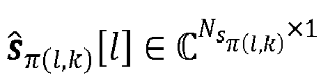
- s ⁇ l K H l H is the concatenation of the data symbols s ⁇ l k l ⁇ C N S ⁇ l k ⁇ 1 for all the K receivers scheduled on the l- th subcarrier, and n ⁇ ( l,k ) [ l ] is the noise vector for the ⁇ ( l , k )-th receiver.
- H ⁇ ( l,k ) ( l ) may denote the perfect CSIR if it is known, or it may denote an estimation of CSIR obtained by a dedicated method.
- n ⁇ ( l,k ) [ l ] is a Gaussian vector. For instance, n ⁇ l k l ⁇ C 0 , ⁇ 2 I N r ⁇ l k , where ⁇ 2 > 0.
- ⁇ F RF F BB l ⁇ F 2 P tot l , where P tot [ l ] is the total transmitting power on the l -th subcarrier and ⁇ M ⁇ F is a norm of a matrix M , for instance the Frobenius norm.
- the RF precoder/combiners of the hybrid architecture may be implemented by phase shifters, each transceiver being connected to each antenna through a network of phase shifters.
- ⁇ prec is the discrete set of the quantization phase for the phase shifters at transmitter and ⁇ comb ⁇ l k is the discrete set of the quantization phase for the phase shifters at receiver ⁇ ( l,k ) .
- minimum mean square error (MMSE) base band digital beamforming may be used at the receiver ⁇ ( l,k ) .
- the user scheduling i.e. the determination of the MU groups
- the RF beamforming design i.e. the determination of the RF beamforming matrices F RF , W RF, ⁇ ( l,k )
- these algorithms first determine the user groups based on a predefined scheduling criterion, and then determine the RF beamforming matrices F RF , W RF, ⁇ ( l,k ) based on a predefined RF beamforming criterion.
- the invention relates to a beamforming method implemented by a computer for enabling analog precoding in a millimeter wave communication system comprising a transmitter being able to serve a plurality of receivers over a plurality of subcarriers, the method comprising:
- millimeter wave systems are submitted to additional constraints with respect to the conventional communication systems (such as the RF precoding and combining codebooks, non-frequency selective property of the RF precoder and combiner, etc.). Therefore, for these mmWave systems, the precoder and scheduling design have to take into account these specific constraints, and the design is very different from conventional sub-6GHz systems.
- the present invention proposes to solve the problem of beamforming design under these specific constraints, with a multistage method based on a joint alternate optimization of the scheduling problem (step b/ of the method) and RF beamforming (step a/ of the method).
- /b/ may be performed after /a/.
- the multi-user groups may be obtained in a previous iteration of the joint determination, and in /b/ the value of the analog precoding matrix F RF may be obtained in a current iteration of /a/.
- /b/ may be performed before /a/.
- the multi-user groups may be obtained in a current iteration of /b/, and in /b/ the value of the analog precoding matrix F RF may be obtained in a previous iteration of the joint determination.
- the analog precoding may be performed by using a set of analog precoding codewords, and /a/ may comprise:
- the method may further comprise: determining at least one analog combining matrix W RF, ⁇ ( l,k ) ; wherein the beamforming function and the scheduling function may be further function of the at least one analog combining matrix W RF, ⁇ ( l,k ) ; wherein the optimization in /a/ may be a joint optimization of the beamforming function with respect to the analog precoding matrix F RF and the at least one analog combining matrix W RF, ⁇ ( l,k ) ; wherein the optimization in /b/ may be performed with a value of an analog combining matrix among the at least one analog combining matrix W RF ⁇ ( l,k ) being fixed; wherein at least one determined analog combining matrix W RF, ⁇ ( l,k ) may be further used for processing at least one signal to transmit to at least one receiver among the plurality of receivers on a subcarrier among the plurality of subcarriers.
- analog combining may be performed by using a set of analog combining codewords, wherein /a/ comprises:
- the method may further comprise:
- receiver sets also called “clustering procedure”
- clustering procedure solving the optimization of F RF and W RF, ⁇ ( l,k ) is transformed into solving K parallelizable optimization of F RF,k and W RF, ⁇ ( l,k ) , each problem having smaller problem dimension and reduced search space, while the sum rate performance degradation due to clustering is negligible.
- this clustering procedure is optional. However, in case such clustering is not performed, the search space (for scheduling design) for the centralized design at the BS is larger and the complexity (for RF precoder/combiner optimization) is increased due to the problem dimension.
- each transmitting matrix among the plurality of transmitting matrices may be an analog precoding codeword and may be associated to a respective subcarrier among the plurality of subcarriers and to a respective receiver among the plurality of receivers.
- each transmitting matrix may correspond to a respective significant communication path between the transmitter and the respective receiver on the respective subcarrier.
- the number of paths with significant gain is very small compared to the size of the channel matrix. Using only significant paths advantageously exploits the channel sparsity, therefore limiting the quantity of information to exchange between the BS and the UE.
- the plurality of receiver sets may be determined based on a similarity measure between at least two transmitting matrices among the plurality of transmitting matrices A T , ⁇ l k l .
- the transmitter may comprise:
- Yet another aspect of the invention relates to a millimeter wave communication system enabling analog precoding and analog combining, the system comprising a transmitter as defined above being able to serve a plurality of receivers over a plurality of subcarriers.
- Yet another aspect of the invention relates to a non-transitory computer readable storage medium, having stored thereon a computer program comprising program instructions, the computer program being loadable into a data-processing unit and adapted to cause the data-processing unit to carry out any one of the above methods when the computer program is run by the data-processing device.
- the analog precoding matrix F RF is selected from a finite-size RF precoding codebook and that the analog combining matrices W RF, ⁇ ( l,k ) are selected from a finite-size RF combining codebook .
- the RF combining codebook may be the same for all receivers, or may be different for the different receivers. Any types of codebooks may be chosen for and , for instance, Grassmannian or beamsteering codebooks. Elements of a codebook are referred to as codewords. A codeword of is referred to as "RF precoding codeword", and a codeword of is referred to "RF combining codeword”.
- the precoding codebook are based on an oversampled Discrete Fourier Transform, DFT, matrix, i.e. a matrix constructed by re-normalizing a sub-matrix selected from a DFT matrix.
- DFT Discrete Fourier Transform
- matrix i.e. a matrix constructed by re-normalizing a sub-matrix selected from a DFT matrix.
- DFT Discrete Fourier Transform
- N os is the oversampling ratio
- FFT(X) returns the discrete Fourier transform of X
- eye(sz) returns an array of size sz ⁇ sz with ones on the main diagonal and zeros elsewhere
- sqrt(x) returns the square root of a number x
- norm(A) returns a normalized matrix obtained from A (i.e., for each column of A, all coefficients of the column
- the final matrix W is a submatrix of W 2 obtained by selecting only the first 1 to N t rows, and the first 1 to N os * N t columns of W 2 .
- Each column of the resulting matrix W corresponds to a codeword of the precoding codebook.
- the codebook precoding has N os * N t codewords of size N t ⁇ 1 each.
- C prec c 1 ... c N os ⁇ N t
- each codeword in the codebook is a length N t vector, where the oversampling rate is N os > 1, is a N t ⁇ ( N os * N t ) matrix with each column serving as a precoding codeword.
- the base band beamforming design i.e. the determination of digital precoding and combining matrices
- any method may be used for determining the base band beamforming matrices.
- the present invention proposes a joint determination of G l
- Figure 3 is a flow chart describing a joint determination, at the transmitter, of MU groups G l
- l 1 L , RF precoder F RF and RF combiners W RF, ⁇ ( l,k ) in a possible embodiment of the invention.
- this determination may be performed by using an iterative procedure in which each iteration comprises two steps:
- l 1 L g ⁇ l k , F RF , W RF , ⁇ l k or G l
- l 1 L g ⁇ l k , F RF , W RF , ⁇ l k
- Another possible strategy may consist in choosing the users having the largest amount of packets in the UE buffer (for Uplink transmission) or the largest amount of dedicated packets in BS buffer (for Downlink transmission).
- Steps 1/ and 2/ may be alternatively repeated until a predefined convergence criterion 304 is met.
- This convergence criterion 304 may be, for instance, based on a mathematical distance between a matrix at a current iteration and the corresponding matrix at the previous iteration. If the distance is lower a predefined threshold, the convergence criterion is met, and G l
- l 1 L , F RF , W RF, ⁇ ( l,k ) are outputted 305.
- the optimization problem of step 1/ may be first solved without codebook constraints, i.e. by choosing F RF * and W RF , ⁇ l k * that optimize f F RF , W RF , ⁇ l k , G l
- l 1 L without supposing that they belong to RF precoding and combining codebooks and .
- the problem is then a quadratically constrained (due to power constraint) quadratic program, which may be solved for instance by a semidefinite relaxation and randomization procedure.
- F RF (resp. W RF, ⁇ ( l,k ) ) may be defined as being equal to the codeword of the RF precoding codebook (resp. the RF combining codebook ) that is the closest, according to a mathematical distance, to each column of F RF * (resp. W RF , ⁇ l k * ).
- steps 1/ and 2/ may be performed in a different order. In some embodiments, 2/ may be performed before 1/.
- the RF combiners W RF, ⁇ ( l,k ) may be decided and reported to the transmitter in the selected beam pairs. Actually, this may lead to performance degradation, but that case is more aligned with the 3GPP NR Rel. 15 specification. In that case, the RF combiner W RF, ⁇ ( l,k ) are not determined during the above joint optimization, which is only performed between G l
- l 1 L and F RF . Hence, the determination of W RF, ⁇ ( l , k ) may be dropped in some embodiments.
- Each scheduled UE k may then feedback the equivalent channel H k eq l .
- the transmitter may therefore calculate the base band precoder F BB [ l ] for each subcarrier l .
- the receiver UE can implement a base band receive filter W BB,k [ l ].
- the base band receive filter W BB,k [ l ] may be calculated by the transmitter and sent to the receiver by using downlink signaling.
- the channel matrices in angular domain between the BS and the UEs are expected to be "sparse", i.e. to have only a few non-zero entries compared to its size.
- a R , ⁇ l k , i l is a direction vector containing the angle of departure (AoD) (resp. the angle of Arrival (AoA)) information for the corresponding significant path i, and d b , ⁇ ( l,k ), i [ l ] is a complex coefficient indicating the strength of the corresponding significant path i.
- AoD angle of departure
- AoA angle of Arrival
- the AoD direction vectors a T , ⁇ l k , i l can be approximated by codewords of the precoding codebook and the AoA direction vectors a R , ⁇ l k , i l can be approximated by codewords of the combining codebook .
- N spars is a variable that can be determined or configured according to the channel sparsity, the channel estimation accuracy and the feedback capability.
- the beam management procedure comprises the following operations:
- the RF beamforming matrices F RF,k and W RF, ⁇ ( l,k ) can then be chosen, at the BS, based on the index (or the indices) of the selected beam pair(s) and the associated quality indicator(s).
- the UE may feedback the index (indices) in the corresponding codebooks C prec C comb , ⁇ l k of the beam pair(s) a R , ⁇ l k , i l a T , ⁇ l k , i l selected during the beam determination operation, together with the associated quality indicator(s).
- the transmitter may then perform a clustering of the active UEs ⁇ l k ⁇ J into K independent sets , based on all the LJ subspaces A T , ⁇ l k l .
- Such clustering makes it possible to limit the interference between the users in case of a random selection, from different sets, of UEs scheduled on the same subcarrier.
- This random selection can be performed during the initialization of the MU group. For example, if the initialization of the MU groups is based on a random draw, drawing each of the K users in different independent sets leads to lower interference as compared to a complete random selection of K users from the set of all active users.
- Performing the clustering based on the LJ received subspaces A T , ⁇ l k l advantageously exploits the sparsity of the communication channel in mmWave systems, because it uses only limited feedback information (that is, the selected beam pair(s)).
- a similarity or "affinity”
- the principle is that two subspaces associated to a high similarity measure belong to the same cluster, and two subspaces associated to a low similarity measure belong to different clusters.
- clustering may comprise the following steps:
- the above procedure outputs K sets . If A T , ⁇ l k l ⁇ S k , that means that, for the subcarrier l, the UE ⁇ ( l , k) is in the set .
- the present invention is not limited to the class of algorithms presented above. Other algorithms may be used.
- Figure 4 is a flow chart describing a joint determination of MU groups, RF precoder F RF and RF combiners W RF, ⁇ ( l,k ) based on the determined user sets in a possible embodiment of the invention.
- the transmitter may receive 401, from the UEs, the matrices A T , j l , A R , j l and D j [ l ], for all active users j ⁇ J of the cell.
- the joint determination procedure may then begin by initializing 403 the MU groups G l
- l 1 L , for instance by a random draw among all the K user sets .
- the first step 404 of the optimization procedure i.e.
- l 1 L , with the MU groups G l
- l 1 L being fixed.
- Step 405 corresponds to the second step of the optimization procedure presented above (i.e.
- step 303 of Figure 3 during which the MU groups G l
- l 1 L are determined by optimizing a predefined scheduling design criterion g ( ⁇ ( l,k ), F RF,k , W RF, ⁇ ( l,k ) ), the RF beamforming matrices W RF, ⁇ ( l,k ) and F RF , k being fixed.
- Steps 404 and 405 may be alternatively repeated until a predefined convergence criterion 406 is met.
- the determination of the RF precoder and combiner according to step 1/ of the procedure may thus be performed as follows:
- the initialization of the RF combiner W RF , ⁇ l k 0 for all scheduled users may be performed by a random selection of each column of W RF , ⁇ l k 0 in the RF combining codebook .
- rank constraints are satisfied if the ranks of the matrices F RF,k and W RF, ⁇ ( l,k ) are equal to L r ⁇ ( l,k ) . Indeed, in that case, the ranks of the optimal solutions X k opt and Y ⁇ l k opt are also equal to L r ⁇ ( l,k ) . It is considered that rank constraints are not satisfied if at least one of the matrices F RF,k and W RF, ⁇ ( l,k ) have a rank not equal to L r ⁇ ( l,k ) .
- the above optimization is a discrete optimization which can be solved by simple brute force full search or advanced methods such as genetic algorithm.
- the initialization of the RF combiner W RF , ⁇ l k 0 for all scheduled users may be performed as in the previous example.
- the rank constraints of the above procedure are similar to those of the previous example.
- the above optimization is a discrete optimization which can be solved by simple brute force full search or advanced methods such as genetic algorithm.
- Figure 5 is a possible embodiment for a device that enables the present invention.
- the device 500 comprise a computer, this computer comprising a memory 505 to store program instructions loadable into a circuit and adapted to cause circuit 504 to carry out the steps of the present invention when the program instructions are run by the circuit 504.
- the memory 505 may also store data and useful information for carrying the steps of the present invention as described above.
- the circuit 504 may be for instance:
- a screen 601 and a keyboard 602 may be provided and connected to the computer circuit 604.
- figure 3 can represent all or part of the steps of a program which may be executed by a processor located in the transmitter. As such, figure 3 may correspond to the flow chart of the general algorithm of a computer program within the meaning of the invention.
Landscapes
- Engineering & Computer Science (AREA)
- Computer Networks & Wireless Communication (AREA)
- Signal Processing (AREA)
- Physics & Mathematics (AREA)
- Mathematical Physics (AREA)
- Radio Transmission System (AREA)
- Mobile Radio Communication Systems (AREA)
Abstract
- jointly determining an analog precoding matrix F RF and a plurality of multi-user groups


- using the analog precoding matrix F RF for processing at least one signal to transmit;
characterized in that the joint determination comprises:
/a/ optimizing a beamforming function
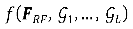

/b/ optimizing a scheduling function
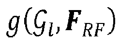

wherein /a/ and /b/ are iteratively repeated.
Description
- The present invention relates to wireless communication and more specifically to techniques for radio resource management in a multi-user (MU) wideband millimeter wave (mmWave) system, for instance a wideband MU mmWave massive Multiple-Input/Multiple-Output (MIMO) system.
- Millimeter wave (mmWave) wireless communication, which makes use of carrier frequencies going from 30 gigahertz (GHz) to 300 GHz, is expected to be a key feature, for instance, for future 5G cellular systems. A major benefit of using such high frequencies is the availability of much greater spectrum for higher data rates.
- Millimeter wave propagation is especially characterized by high path loss in free space, high penetration loss through building materials, weak diffraction, and vulnerability to blockage. Therefore, highly directional adaptive antenna arrays at both transmission and reception sides have to be used for compensating propagation impairments and enabling cellular coverage over distances of few hundred meters.
- Directional arrays are usually constructed using a very large number of antenna elements, for instance tens to several hundreds. In addition to high directional gain, the use of large antenna arrays enhances spatial multiplexing since narrower beams can be realized.
- The radio resource management in a wideband mmWave system is actually much more complicated than in a conventional system below 6 GHz. In the case of systems with large antenna arrays, since the high bandwidth mixed-signal components are expensive and consume lots of power, the number of Radio Frequency (RF) chains at the transceiver needs to be smaller than the number of antennas. In order to reduce the number of RF chains, hybrid analog/digital beamforming architectures are generally used.
- One of the advantages of hybrid architectures is that the additional digital processing can compensate the lack of precision (due, for instance, to phase shifters that only work with a finite phase resolution) of analog processing. However, in the case of a wideband mmWave system, since the analog RF (or simply "RF") beamforming of the wideband system is shared among all subcarriers while the digital base band (or simply "base band") beamforming can be different between subcarriers, the beamforming design (i.e. the design of analog and digital beamformers) for the radio resource management is much more complicate than in a narrow band mmWave system or a conventional LTE system operating below 6 GHz.
- In addition, in a Multi-User (MU) system, a plurality of User Equipments (UE, also referred to as "users", or "receivers" hereinafter) can be assigned to a same set of Resource Blocks (RB) for data transmission. Thus, the radio resource management must take into account both the problems of:
- User grouping to group UEs for MU scheduling; and
- Resource allocation to assign time and frequency resources to the groups of UEs.
- The principle of user scheduling, resource allocation and user grouping to the groups of UEs is represented in
Figure 1 . -
Figure 1 represents acell 101 served by a Base Station (BS) 103 (also referred to hereinafter as "transmitter"), comprising a plurality ofactive UEs plurality 104 of active UEs among theactive UEs Figure 1 . In the case of a wideband system, each scheduled UE may then be assigned to a certain frequency band for transmission during a resource allocation procedure. In the case of a multi-user transmission scheme, a plurality of users can be jointly served in a same time-frequency resource (i.e. a set of Resource Blocks, RBs). To that purpose, a user grouping is performed to formmulti-user groups frequency resource (with l = 1 ... L) may contain the K users that are jointly served on the l-th subcarrier.
-
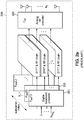
Figures 2a and2b represent examples of a transmitter and a receiver, respectively, in a hybrid wideband wireless system. - According to
figure 2a , thetransmitter 200 is equipped with Nt transmitting antennas and Lt transmitting RF chains. It operates on a wideband system with L subcarriers, and it is assumed that on each subcarrier l (with l = 1, ..., L), K users are jointly scheduled and served by thetransmitter 200. In the following, the indices of the scheduled users on a given subcarrier l are noted π(l, k) (with l = 1, ..., L and k = 1, ..., K). In other words, the user π(l, k) is the k-th user on the l-th subcarrier. - At the
transmitter 200, for each subcarrier l (with l = 1, ..., L), Ns (l) data streams I 1, ..., I NS(l ) are processed by abase band precoder 201, 202 (or "base band precoding matrix") F BB [l] followed by an RF precoder 203 (or "RF precoding matrix") F RF. It has to be noted that the digitalbase band precoders analog RF precoder 203 is the same for all subcarriers. - According to the embodiment represented in
Figure 2b , the π(l,k)-th receiver 210 π(l, k) (with 1 ≤ k ≤ K and 1 ≤ l ≤ L) may be equipped with N rπ(l,k) receiving and L rπ(l,k) receiving RF chains. The π(l,k)-th receiver 210 may receive N sπ(l,k) data streams from the transmitter. The received data streams may be processed by a RF combiner 211 W RF,π(l,k) ∈

th receiver 210 may output N sπ(l,k) data streams 
Figure 2b , there may be more than one base band combiner for the π(l,k)-th receiver. Indeed, the scheduled user π(l,k) on the l-th subcarrier might also be scheduled on other subcarriers l 2, ..., li. - Of course, the architecture represented in
figures 2a and2b is only an example of a hybrid wideband wireless system in which the present method may be performed. Other systems may be considered. For instance, at receivers, there may be only analog combiners instead of both analog and digital combiners. - The global performance of such hybrid wideband wireless system may be quantified by a value, called "figure of merit", and it may be found that the figure of merit is function of the MU groups

- As an example, the case where the figure of merit for the radio resource management is the average wideband sum rate of the downlink (DL) transmission according to a possible embodiment is provided below.
- In this embodiment, it is assumed that K receivers are jointly served for multi-user transmission on each subcarrier. In other embodiments, the number of receivers jointly served may be different for two distinct subcarriers. In the case where K receivers (with K ≥ 2) are jointly served on each subcarrier l (with l = 1, ..., L), the total number of streams transmitted by the transmitter on subcarrier l is equal to


- Furthermore, the following constraints may be assumed:

π(l,k) ≥ L rπ(l,k) ≥ N sπ(l,k) and
- The signal


- In case the user channel matrix (or "channel state information", CSI) H π(l,k)(l) is not perfectly known at the receiver, a channel estimation may be performed in order to estimate the CSI at the Receiver (CSIR). Any method of the state of the art for estimating the CSIR may be performed. In this disclosure, H π(l,k)(l) may denote the perfect CSIR if it is known, or it may denote an estimation of CSIR obtained by a dedicated method.
- It may be assumed that the power of data symbol vector satisfies
 denotes the statistical expectation and Isz denotes the identity matrix of size sz, and that n π(l,k)[l] is a Gaussian vector. For instance,


- The RF precoder/combiners of the hybrid architecture may be implemented by phase shifters, each transceiver being connected to each antenna through a network of phase shifters. In this case, the elements of matrices F RF and W RF,π(l,k) may satisfy:


where Φprec is the discrete set of the quantization phase for the phase shifters at transmitter and
- In one embodiment, minimum mean square error (MMSE) base band digital beamforming may be used at the receiver π(l,k). The base band precoder F BB [l] may be written as a concatenation of K sub-matrices F BB,π(l,k)[l] with k = 1, ..., K:



- The average wideband sum rate of the downlink (DL) transmission is:


- Jointly optimize a function of

- In algorithms of the prior art, the user scheduling, i.e. the determination of the MU groups, and the RF beamforming design, i.e. the determination of the RF beamforming matrices F RF,W RF,π(l,k) , are processed sequentially and independently of each other. More specifically, these algorithms first determine the user groups
 based on a predefined scheduling criterion, and then determine the RF beamforming matrices F RF, W RF,π(l,k) based on a predefined RF beamforming criterion. However, such sequential processing of both user scheduling and RF beamforming problems leads to performance degradations.
- There is thus a need for methods for user scheduling and RF beamforming design in a wideband multi-user massive MIMO system with good performances while avoiding high computational complexity and huge signaling overhead.
- The invention relates to a beamforming method implemented by a computer for enabling analog precoding in a millimeter wave communication system comprising a transmitter being able to serve a plurality of receivers over a plurality of subcarriers, the method comprising:
- jointly determining an analog precoding matrix F RF and a plurality of multi-user groups , each multi-user group
 being associated to a respective subcarrier l among the plurality of subcarriers, each multi-user group
 containing a plurality of receivers among the plurality of receivers to be jointly served for a data transmission on the respective subcarrier l; and
- using the analog precoding matrix F RF for processing at least one signal to transmit to at least one receiver among the plurality of receivers on a subcarrier among the plurality of subcarriers;
- /a/ optimizing a beamforming function
 with respect to the analog precoding matrix F RF , the multi-user groups
 being fixed;
- /b/ optimizing a scheduling function
 with respect to the multi-user groups
 , a value of the analog precoding matrix F RF being fixed;
- As mentioned above, millimeter wave systems are submitted to additional constraints with respect to the conventional communication systems (such as the RF precoding and combining codebooks, non-frequency selective property of the RF precoder and combiner, etc.). Therefore, for these mmWave systems, the precoder and scheduling design have to take into account these specific constraints, and the design is very different from conventional sub-6GHz systems. The present invention proposes to solve the problem of beamforming design under these specific constraints, with a multistage method based on a joint alternate optimization of the scheduling problem (step b/ of the method) and RF beamforming (step a/ of the method).
- In an embodiment, /b/ may be performed after /a/. In /a/ the multi-user groupsmay be obtained in a previous iteration of the joint determination, and in /b/ the value of the analog precoding matrix F RF may be obtained in a current iteration of /a/.

- It is meant by "previous" and "current" iteration two successive iterations of the method, the "previous" iteration designating the iteration just preceding the "current" iteration.
- In an alternative embodiment, /b/ may be performed before /a/. In /a/ the multi-user groupsmay be obtained in a current iteration of /b/, and in /b/ the value of the analog precoding matrix F RF may be obtained in a previous iteration of the joint determination.

- In one or several embodiments, the analog precoding may be performed by using a setof analog precoding codewords, and /a/ may comprise:

- determining a first matrix


 of analog precoding codewords;
- determining at least one analog precoding codewords, each determined analog precoding codeword minimizing a distance to a column of the first matrix

- determining the analog precoding matrix F RF whose columns are equal to the determined at least one analog precoding codewords.
- In addition the method may further comprise: determining at least one analog combining matrix W RF,π(l,k);
wherein the beamforming function and the scheduling function may be further function of the at least one analog combining matrix W RF,π(l,k);
wherein the optimization in /a/ may be a joint optimization of the beamforming function with respect to the analog precoding matrix F RF and the at least one analog combining matrix W RF,π(l,k);
wherein the optimization in /b/ may be performed with a value of an analog combining matrix among the at least one analog combining matrix W RFπ(l,k) being fixed;
wherein at least one determined analog combining matrix W RF,π(l,k) may be further used for processing at least one signal to transmit to at least one receiver among the plurality of receivers on a subcarrier among the plurality of subcarriers. - Furthermore, the analog combining may be performed by using a setof analog combining codewords, wherein /a/ comprises:

- determining a second matrix

 of analog combining codewords;
- determining at least one analog combining codewords, each determined analog combining codeword minimizing a distance to a column of the second matrix

- determining an analog combining matrix W RF,π(l,k) whose columns are equal to the determined at least one analog combining codewords.
- In one or several embodiments, the method may further comprise:
- receiving a plurality of transmitting matrices
 of analog precoding codewords;
- determining, based on the plurality of transmitting matrices
 , each receiver set
 comprising one or more receiver among the plurality of receivers, each receiver among the one or more receiver being associated to a subcarrier among the plurality of subcarriers;
- determining a plurality of analog precoding submatrices F RF,k, each analog precoding submatrix F RF,k corresponding to a part a the analog precoding matrix F RF associated to receivers of a respective receiver set .

- The determination of receiver sets (also called "clustering procedure") provides a better compromise complexity-performance. With this clustering procedure, solving the optimization of F RF and W RF,π(l,k) is transformed into solving K parallelizable optimization of F RF,k and W RF,π(l,k), each problem having smaller problem dimension and reduced search space, while the sum rate performance degradation due to clustering is negligible.
- It has to be understood that this clustering procedure is optional. However, in case such clustering is not performed, the search space (for scheduling design) for the centralized design at the BS is larger and the complexity (for RF precoder/combiner optimization) is increased due to the problem dimension.
- In an embodiment, each transmitting matrix among the plurality of transmitting matrices may be an analog precoding codeword and may be associated to a respective subcarrier among the plurality of subcarriers and to a respective receiver among the plurality of receivers.
- Furthermore, each transmitting matrix may correspond to a respective significant communication path between the transmitter and the respective receiver on the respective subcarrier.
- In mmWave communication systems, the number of paths with significant gain is very small compared to the size of the channel matrix. Using only significant paths advantageously exploits the channel sparsity, therefore limiting the quantity of information to exchange between the BS and the UE.
- Furthermore, the plurality of receiver setsmay be determined based on a similarity measure between at least two transmitting matrices among the plurality of transmitting matrices


- Another aspect of the invention relates to a transmitter in a millimeter wave communication system enabling analog precoding and analog combining, the transmitter being able to serve a plurality of receivers over a plurality of subcarriers. The transmitter may comprise:
- a circuit for jointly determine an analog precoding matrix F RF and a plurality of multi-user groups , each multi-user group
 being associated to a respective subcarrier l among the plurality of subcarriers, each multi-user group
 containing a plurality of receivers among the plurality of receivers to be jointly served for a data transmission on the respective subcarrier l; and
- a circuit for processing, by using the analog precoding matrix F RF, at least one signal to transmit to at least one receiver among the plurality of receivers on a subcarrier among the plurality of subcarriers; and
- /a/ optimizing a beamforming function
 with respect to the analog precoding matrix F RF, the multi-user groups
 being fixed;
- /b/ optimizing a scheduling function
 with respect to the multi-user groups
 , a value of the analog precoding matrix F RF being fixed;
- Yet another aspect of the invention relates to a millimeter wave communication system enabling analog precoding and analog combining, the system comprising a transmitter as defined above being able to serve a plurality of receivers over a plurality of subcarriers.
- Yet another aspect of the invention relates to a non-transitory computer readable storage medium, having stored thereon a computer program comprising program instructions, the computer program being loadable into a data-processing unit and adapted to cause the data-processing unit to carry out any one of the above methods when the computer program is run by the data-processing device.
- Other features and advantages of the method and apparatus disclosed herein will become apparent from the following description of non-limiting embodiments, with reference to the appended drawings.
- The present invention is illustrated by way of example, and not by way of limitation, in the figures of the accompanying drawings, in which like reference numerals refer to similar elements and in which:
-
Figure 1 represents user scheduling, resource allocation and user grouping in a wideband multi-user system; -
Figure 2a represents an example of a transmitter in a hybrid wideband wireless system; -
Figure 2b represents an example of a receiver in a hybrid wideband wireless system; -
Figure 3 is a flow chart describing a joint determination, at the transmitter, of MU groups, RF precoder F RF and RF combiners W RFπ(l,k) in a possible embodiment of the invention; -
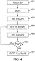
Figure 4 is a flow chart describing a joint determination of MU groups, RF precoder F RF and RF combiners W RFπ(l,k) based on the determined user setsin a possible embodiment of the invention;
-
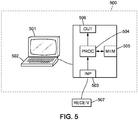
Figure 5 is a possible embodiment for a device that enables the present invention. - Expressions such as "comprise", "include", "incorporate", "contain", "is" and "have" are to be construed in a non-exclusive manner when interpreting the description and its associated claims, namely construed to allow for other items or components which are not explicitly defined also to be present. Reference to the singular is also to be construed in be a reference to the plural and vice versa.
- In the following, it is assumed that the analog precoding matrix F RF is selected from a finite-size RF precoding codebookand that the analog combining matrices W RF,π(l,k) are selected from a finite-size RF combining codebook
 . The RF combining codebook may be the same for all receivers, or may be different for the different receivers. Any types of codebooks may be chosen for
 and
and , for instance, Grassmannian or beamsteering codebooks. Elements of a codebook are referred to as codewords. A codeword of
 is referred to as "RF precoding codeword", and a codeword of
 is referred to "RF combining codeword".
- In one embodiment, the precoding codebookare based on an oversampled Discrete Fourier Transform, DFT, matrix, i.e. a matrix constructed by re-normalizing a sub-matrix selected from a DFT matrix. Such matrix may algorithmically be obtained as follows:


- Another example of a precoding codebookthat may be used in the present invention is given below:


- where the t-th component (with t = 1, ..., Nt ) of a codeword vector c i is equal to

- The beam direction for the i-th (for i = 1, ..., Nos * Nt ) codeword is

- In both case, each codeword in the codebook is a length Nt vector, where the oversampling rate is Nos > 1,is a Nt × (Nos * Nt ) matrix with each column serving as a precoding codeword.

- Of course, other precoding codebooks may be used.
- The present invention proposes to jointly perform user MU grouping (i.e. determining the MU groups


-
Figure 3 is a flow chart describing a joint determination, at the transmitter, of MU groups
- 1/ A
first step 302 during which the RF precoder F RF and the RF combining matrices W RF,π(l,k) are determined by optimizing a predefined RF beamforming design criterion

Such optimization may be a maximization or a minimization:

- 2/ A
second step 303 during which the MU groups
- Such optimization may be a maximization or a minimization:


- Before the first iteration of the above procedure, the MU groups
 . Another possible strategy may consist in choosing the users having the largest amount of packets in the UE buffer (for Uplink transmission) or the largest amount of dedicated packets in BS buffer (for Downlink transmission).
-
Steps 1/ and 2/ may be alternatively repeated until apredefined convergence criterion 304 is met. Thisconvergence criterion 304 may be, for instance, based on a mathematical distance between a matrix at a current iteration and the corresponding matrix at the previous iteration. If the distance is lower a predefined threshold, the convergence criterion is met, and
- For instance, the optimization problem of
step 1/ may be first solved without codebook constraints, i.e. by choosing

 and
and . The problem is then a quadratically constrained (due to power constraint) quadratic program, which may be solved for instance by a semidefinite relaxation and randomization procedure. Then, F RF (resp. W RF,π(l,k)) may be defined as being equal to the codeword of the RF precoding codebook
 (resp. the RF combining codebook
 ) that is the closest, according to a mathematical distance, to each column of


- Of course, steps 1/ and 2/ may be performed in a different order. In some embodiments, 2/ may be performed before 1/.
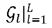
- It has to be noticed that the RF combiners W RF,π(l,k) may be decided and reported to the transmitter in the selected beam pairs. Actually, this may lead to performance degradation, but that case is more aligned with the 3GPP NR Rel. 15 specification. In that case, the RF combiner W RF,π(l,k) are not determined during the above joint optimization, which is only performed between
- In case where W RF,k is determined during the joint optimization procedure at transmitter's side, the transmitter may inform each scheduled UE k the subcarrier(s) it has been assigned and the indices of each column vector of the W RF,k in the RF combining codebook. Upon receiving these indices, each scheduled UE k may implement the RF combiner accordingly. The transmitter will implement the RF precoder F RF. Once the RF beamforming matrices at transmitter and receiver have been chosen, the transmitter may send RSs to estimate the equivalent channel


- Each scheduled UE k may then feedback the equivalent channel

- Some embodiments of the above joint determination procedure are now provided. These embodiments exploit the sparsity of the communication channel in mmWave systems. Indeed, in case of a mmWave system with large antenna arrays, many paths are highly attenuated, and the number Nspars of paths with significant gain is expected to be small compared to the size Nt × N r
π(l,k) of the channel matrix H π(l,k)[l]. By "significant gain", it is meant that the gain of the path is greater than a predefined threshold. If the gain is lower than this threshold, it is set to zero. Consequently, and due to the high directivity of antenna arrays, the channel matrices in angular domain between the BS and the UEs are expected to be "sparse", i.e. to have only a few non-zero entries compared to its size. - The channel matrix H π(l,k)[l] of the communication link between the BS and the UE π(l,k) on the l-th subcarrier may thus be described with a very small number of parameters:


- In one embodiment, the AoD direction vectors
 and the AoA direction vectors
 .
.
- It has to be noticed that Nspars is a variable that can be determined or configured according to the channel sparsity, the channel estimation accuracy and the feedback capability.
- The channel matrix H π(l,k)[l] may also be written:


- Several algorithms of the prior art have been developed for determining the above sparse representation of the channel matrix, and outputting for instance the set of parameters


EP16306171.6 - According to the 5G NR specification, the beam management procedure comprises the following operations:
- Beam sweeping: A spatial area is covered with a set of beams transmitted and received according to pre-specified intervals and directions;
- Beam measurement: Reference Signals (RSs) are transmitted from the BS to the UEs, for all possible BS/UE beam pairs (i.e. for all the possible pairs of a precoding matrix


- Beam determination: At least one beam pair is selected, at the UE, based on its performance metric. For instance, the beam pair(s) that maximize(s) the performance metric, or the P beam pairs (with P a predefined integer) having the P higher performance metrics, may be selected;
- Beam reporting: The UE may report, to the BS, the index (or the indices) of the selected beam pair(s) and the associated quality indicator(s).
- The RF beamforming matrices F RF,k and W RF,π(l,k) can then be chosen, at the BS, based on the index (or the indices) of the selected beam pair(s) and the associated quality indicator(s).
- In one embodiment of the invention, during the beam reporting operation described above, the UE may feedback the index (indices) in the corresponding codebooks


- The transmitter may therefore collect all the indices of the selected beam pair(s), or equivalently all the matrices (also called "subspaces" hereinafter)

 being the set of active UEs of the cell), and for all subcarriers l = 1, ..., L. The transmitter may then perform a clustering of the active UEs
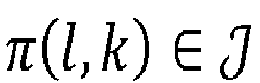 , based on all the LJ subspaces
 of all active users.
- Performing the clustering based on the LJ received subspaces

- In one embodiment, the clustering of all the active UEs of the cell and for all the subcarriers into K independent sets is based on a similarity (or "affinity") measure between the subspaces


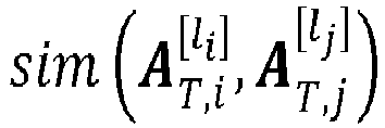
- Compute the similarity matrix M S of dimension LJ × LJ (J being the cardinality of ), whose (i,j)-th element (i being the row index and j being the column index) is equal to

- Let D be the diagonal matrix whose (i,i)-th element is equal to the sum of the elements of the i-th row of M S ; construct the matrix Z = D -1/2 M S D -1/2;
- Find the K largest eigenvalues of Z (the corresponding eigenvectors being chosen to be orthogonal to each other in case of repeated eigenvalues) and form the
matrix 
- Form the matrix M 2 from M 1 by normalizing each of the rows of M 1 to unit length;
- Considering each row of M 2 as a point in , cluster these rows into K clusters via a clustering algorithm that attempts to minimize distortion (for instance, the K-means algorithm); and

- Assign the original subspace

- In the above,


- The above procedure outputs K sets. If

 .
.
- Any mathematical similarity measure can be used. Two examples of similarity measures sim 1 and sim 2 between two subspaces S 1 and S 2 are given below:


- Of course, the present invention is not limited to the class of algorithms presented above. Other algorithms may be used. For instance, the sets may be formed by a random draw among the set of subspaces

- In one or several embodiments, the joint determination of MU groups
 .
.
Figure 4 is a flow chart describing a joint determination of MU groups, RF precoder FRF and RF combiners W RF,π(l,k) based on the determined user setsin a possible embodiment of the invention.
- In the following, the RF precoder F RF is viewed as a concatenation of K RF precoding submatrices F RF,k (for k = 1, ..., K), where F RF,k is the part of the RF precoder corresponding to the users of the clustering set: F RF = [ F RF,1 ... F RF,K ].

- As detailed above, the transmitter may receive 401, from the UEs, the matrices


clustering 402 of the subspaces . The joint determination procedure may then begin by initializing 403 the MU groups
 . Then, the
first step 404 of the optimization procedure (i.e.step 302 ofFigure 3 ) may comprise a determination of all the RF precoding submatrices F RF,k (for k = 1, ..., K) (and eventually the RF combining matrices W RF,π(l,k) for k = 1, ..., K and l = 1, ..., L) by optimizing a predefined RF beamforming design criterion

step 303 ofFigure 3 ), during which the MU groups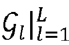
Steps predefined convergence criterion 406 is met. When theconvergence criterion 406 is met,
- A first example of such joint determination procedure is presented below, in the case of a maximization of the average wideband sum rate of the system. The user setsand the matrices


- Due to the information theory duality between an information theory broadcast channel and its dual multiple access channel, the sum rate of the downlink transmission across all the subcarriers may be lower bounded by its dual uplink transmission over all subcarriers with equal power allocation. Therefore, the capacity of the downlink transmission across all subcarriers can be lower bounded by:

- Assuming that the clustering reduces the multi-user interference between different cluster sets, we can write that

- Therefore the right-hand side of the above inequality may be approximated by:

- According to the sparse representation of the channel matrix, H π(l,k)[l] may be replaced by


- The RF beamforming design criterion may thus be written:

- The determination of the RF precoder and combiner according to
step 1/ of the procedure may thus be performed as follows: - Let
 be the set
 with all repeating elements removed. |
 | denotes the cardinality of
 . Define the mapping function:

 is the


- Initialize RF combiner

Let
- While a convergence criterion is not met, perform:
- ∘ For k = 1, ..., K, compute


- ∘ For


- ∘ t =
t + 1
- ∘ For k = 1, ..., K, compute
- If rank constraints are satisfied, then let


- If rank constraints are not satisfied, then perform the following randomization procedure, for k = 1, ..., K:
- ∘ Generate random Gaussian matrices V 1 and V 2, each component of V 1 and V 2 being independent and identically distributed (i.i.d.) according to a distribution

- ∘ Let


- ∘ Define:


- ∘ Normalize each column of F RF,k and W RF,π(l,k) such that they are unit vector.
- ∘ Repeat Nrand times the above steps of the randomization procedure (Nrand being a predefined integer number), and choose the one that yields to the largest value of the considered RF beamforming design criterion.
- ∘ Generate random Gaussian matrices V 1 and V 2, each component of V 1 and V 2 being independent and identically distributed (i.i.d.) according to a distribution
- Find the codewords in the respective codebooks and
 which minimize a distance with the columns of F RF,k and W RF,π(l,k).
- The initialization of the RF combiner

 .
.
- In the above procedure, it is considered that rank constraints are satisfied if the ranks of the matrices F RF,k and W RF,π(l,k) are equal to L r
π(l,k) . Indeed, in that case, the ranks of the optimal solutions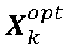

π(l,k) . It is considered that rank constraints are not satisfied if at least one of the matrices F RF,k and W RF,π(l,k) have a rank not equal to L rπ(l,k) . - It has to be noticed that the larger Nrand is, the more accurate the randomization procedure is.
- Always in the case of a maximization of the average wideband sum rate of the system, the scheduling design criterion to maximize may be:

- Knowing that the RF precoders and combiners are fixed during the MU grouping design, the above optimization is a discrete optimization which can be solved by simple brute force full search or advanced methods such as genetic algorithm.
- A second example of the optimization procedure is now provided, in the case of a maximization of the minimal receive equivalent channel gain. In that case, the RF beamforming design criterion may be written:

- The determination of the RF precoder and combiner according to
step 1/ of the above procedure may thus be performed as follows: - Let ,
 and
and

- Initialize RF combiner

- Let

- Initialize t = 0.
- While a convergence criterion is not met, perform:
- ∘ For k = 1, ..., K, compute


- ∘ For



- ∘ t =
t + 1
- ∘ For k = 1, ..., K, compute
- If rank constraints are satisfied, let


- If rank constraints are not satisfied, then perform the randomization procedure of the first example
- Find the codewords in the respective codebooks and
 which minimize a distance with the columns of F RF,k and W RF,π(l,k) .
- The initialization of the RF combiner

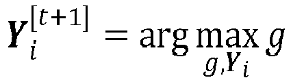
- Always in the case of a maximization of the minimal receive equivalent channel gain, the scheduling design criterion to maximize may be:

- Many other RF beamforming / scheduling design criteria may be used.
- For instance, in the context of wideband user scheduling (i.e. each scheduled user occupies all the subcarriers and no frequency multiplexing that allocates different users on different subcarriers is allowed), an example of scheduling design criterion to maximize is:

- In the context of fairness issue for scheduling, an example of scheduling design criterion to maximize is:

- By "in the context of fairness issue for scheduling", it is meant the following. By optimizing the scheduling criterion, UEs with potentially higher rate are more likely to be scheduled. This is not "fair" from the system operation point of view, because some potentially low rate UEs might never get the chance to transmit. In order to overcome this problem, many techniques can be applied. The above design criterion is an example of such techniques consists, as above, in introducing some positive weighting factors α π(l,k) to adjust the instantaneous rate of user. For example if one UE has not been scheduled for a long time, its weighting factor may be increased. In this case even if the user has lower rate, it is more likely to be scheduled after some time.
- Knowing that the RF precoders and combiners are fixed during the MU grouping design, the above optimization is a discrete optimization which can be solved by simple brute force full search or advanced methods such as genetic algorithm.
-
Figure 5 is a possible embodiment for a device that enables the present invention. - In this embodiment, the device 500 comprise a computer, this computer comprising a
memory 505 to store program instructions loadable into a circuit and adapted to causecircuit 504 to carry out the steps of the present invention when the program instructions are run by thecircuit 504. - The
memory 505 may also store data and useful information for carrying the steps of the present invention as described above. - The
circuit 504 may be for instance: - a processor or a processing unit adapted to interpret instructions in a computer language, the processor or the processing unit may comprise, may be associated with or be attached to a memory comprising the instructions, or
- the association of a processor / processing unit and a memory, the processor or the processing unit adapted to interpret instructions in a computer language, the memory comprising said instructions, or
- an electronic card wherein the steps of the invention are described within silicon, or
- a programmable electronic chip such as a FPGA chip (for « Field-Programmable Gate Array »).
- For instance, the device may be comprised in a transmitter, and the computer may comprise an
input interface 503 for the reception of channel information, for instance matrices


output interface 506 for providing the MU groups, and the RF precoding and combining matrices. - To ease the interaction with the computer, a screen 601 and a keyboard 602 may be provided and connected to the computer circuit 604.
- Furthermore, the flow chart represented in
figure 3 can represent all or part of the steps of a program which may be executed by a processor located in the transmitter. As such,figure 3 may correspond to the flow chart of the general algorithm of a computer program within the meaning of the invention. - A person skilled in the art will readily appreciate that various parameters disclosed in the description may be modified and that various embodiments disclosed may be combined without departing from the scope of the invention. Of course, the present invention is not limited to the embodiments described above as examples. It extends to other variants.


Claims (13)
- A beamforming method implemented by a computer for enabling analog precoding in a millimeter wave communication system comprising a transmitter (200) being able to serve a plurality of receivers (210) over a plurality of subcarriers, the method comprising:- jointly determining an analog precoding matrix (203) F RF and a plurality of multi-user groups, each multi-user group
 being associated to a respective subcarrier l among the plurality of subcarriers, each multi-user group
 containing a plurality of receivers (210) among the plurality of receivers (210) to be jointly served for a data transmission on the respective subcarrier l; and
 - using the analog precoding matrix (203) F RF for processing at least one signal to transmit to at least one receiver (210) among the plurality of receivers (210) on a subcarrier among the plurality of subcarriers;characterized in that the joint determination of the analog precoding matrix (203) F RF and the plurality of multi-user groupscomprises:
 /a/ optimizing (302, 404) a beamforming function
 with respect to the analog precoding matrix (203) F RF, the multi-user groups
 being fixed;
 /b/ optimizing (303, 405) a scheduling functionwherein /a/ and /b/ are iteratively repeated until a stopping criterion (304, 406) is met.
 with respect to the multi-user groups
 , a value of the analog precoding matrix (203) F RF being fixed;
- The method of claim 1, wherein /b/ is performed after /a/, wherein in /a/ the multi-user groupsare obtained in a previous iteration of the joint determination, and wherein in /b/ the value of the analog precoding matrix (203) F RF is obtained in a current iteration of /a/.

- The method of claim 1, wherein /b/ is performed before /a/, wherein in /a/ the multi-user groupsare obtained in a current iteration of /b/, and wherein in /b/ the value of the analog precoding matrix (203) F RF is obtained in a previous iteration of the joint determination.

- The method of any of the preceding claims, wherein the analog precoding is performed by using a setof analog precoding codewords, wherein /a/ comprises:
 - determining a first matrix

 of analog precoding codewords;
 - determining at least one analog precoding codewords, each determined analog precoding codeword minimizing a distance to a column of the first matrix
 - determining the analog precoding matrix (203) F RF whose columns are equal to the determined at least one analog precoding codewords.
 - The method of any of the preceding claims, further comprising determining at least one analog combining matrix (211) W RF,π(l,k);
wherein the beamforming function and the scheduling function are further function of the at least one analog combining matrix (211) W RF,π(l,k);
wherein the optimization in /a/ is a joint optimization of the beamforming function with respect to the analog precoding matrix (203) F RF and the at least one analog combining matrix (211) W RF,π(l,k);
wherein the optimization in /b/ is performed with a value of an analog combining matrix (211) among the at least one analog combining matrix (211) W RF,π(l,k) being fixed;
wherein at least one determined analog combining matrix (211) W RF,π(l,k) is further used for processing at least one signal to transmit to at least one receiver (210) among the plurality of receivers (210) on a subcarrier among the plurality of subcarriers. - The method of claim 5, wherein the analog combining is performed by using a setof analog combining codewords, wherein /a/ comprises:
 - determining a second matrix
 of analog combining codewords;
 - determining at least one analog combining codewords, each determined analog combining codeword minimizing a distance to a column of the second matrix
 - determining an analog combining matrix (211) W RF,π(l,k) whose columns are equal to the determined at least one analog combining codewords.
 - The method of any of claims 4 to 6, further comprising:- receiving a plurality of transmitting matrices
 of analog precoding codewords;
 - determining (402), based on the plurality of transmitting matriceswherein /a/ comprises:
 , each receiver set
 comprising one or more receiver (210) among the plurality of receivers, each receiver (210) among the one or more receiver (210) being associated to a subcarrier among the plurality of subcarriers;
 - determining a plurality of analog precoding submatrices F RF,k, each analog precoding submatrix F RF,k corresponding to a part a the analog precoding matrix (203) F RF associated to receivers (210) of a respective receiver set.
- The method of claim 7, wherein each transmitting matrix among the plurality of transmitting matrices is an analog precoding codeword and is associated to a respective subcarrier among the plurality of subcarriers and to a respective receiver (210) among the plurality of receivers (210).
- The method of claim 8, wherein each transmitting matrix corresponds to a respective significant communication path between the transmitter (200) and the respective receiver (210) on the respective subcarrier.
- The method of any of claims 7 to 9, wherein the plurality of receiver setsare determined based on a similarity measure between at least two transmitting matrices among the plurality of transmitting matrices


- A transmitter (200) of a millimeter wave communication system enabling analog precoding and analog combining, the transmitter (200) being able to serve a plurality of receivers (210) over a plurality of subcarriers, the transmitter (200) comprising:- a circuit for jointly determine an analog precoding matrix (203) F RF and a plurality of multi-user groups, each multi-user group
 being associated to a respective subcarrier l among the plurality of subcarriers, each multi-user group
 containing a plurality of receivers (210) among the plurality of receivers (210) to be jointly served for a data transmission on the respective subcarrier l; and
 - a circuit for processing, by using the analog precoding matrix (203) F RF, at least one signal to transmit to at least one receiver (210) among the plurality of receivers (210) on a subcarrier among the plurality of subcarriers; andcharacterized in that the joint determination of the analog precoding matrix (203) F RF and the plurality of multi-user groupscomprises:
 /a/ optimizing (302, 404) a beamforming function
 with respect to the analog precoding matrix (203) F RF , the multi-user groups
 being fixed;
 /b/ optimizing (303, 405) a scheduling functionwherein /a/ and /b/ are iteratively repeated until a stopping criterion (304, 406) is met.
 with respect to the multi-user groups
 , a value of the analog precoding matrix (203) F RF being fixed;
- A millimeter wave communication system enabling analog precoding and analog combining, the system comprising a transmitter (200) according to claim 11 being able to serve a plurality of receivers (210) over a plurality of subcarriers.
- A non-transitory computer readable storage medium, having stored thereon a computer program comprising program instructions, the computer program being loadable into a data-processing unit and adapted to cause the data-processing unit to carry out the method of any of claims 1 to 10 when the computer program is run by the data-processing device.
Priority Applications (6)
| Application Number | Priority Date | Filing Date | Title |
|---|---|---|---|
| EP19305056.4A EP3683975A1 (en) | 2019-01-17 | 2019-01-17 | Method for enabling analog precoding and analog combining |
| US17/298,495 US11374642B2 (en) | 2019-01-17 | 2020-01-16 | Method for enabling analog precoding and analog combining |
| JP2021523085A JP7170863B2 (en) | 2019-01-17 | 2020-01-16 | Method for enabling analog precoding and analog combining |
| KR1020217021826A KR102485536B1 (en) | 2019-01-17 | 2020-01-16 | How to enable analog precoding and analog combining |
| CN202080008914.6A CN113287265B (en) | 2019-01-17 | 2020-01-16 | Methods enabling analog precoding and analog combining |
| PCT/JP2020/002198 WO2020149422A1 (en) | 2019-01-17 | 2020-01-16 | Method for enabling analog precoding and analog combining |
Applications Claiming Priority (1)
| Application Number | Priority Date | Filing Date | Title |
|---|---|---|---|
| EP19305056.4A EP3683975A1 (en) | 2019-01-17 | 2019-01-17 | Method for enabling analog precoding and analog combining |
Publications (1)
| Publication Number | Publication Date |
|---|---|
| EP3683975A1 true EP3683975A1 (en) | 2020-07-22 |
Family
ID=65324305
Family Applications (1)
| Application Number | Title | Priority Date | Filing Date |
|---|---|---|---|
| EP19305056.4A Withdrawn EP3683975A1 (en) | 2019-01-17 | 2019-01-17 | Method for enabling analog precoding and analog combining |
Country Status (6)
| Country | Link |
|---|---|
| US (1) | US11374642B2 (en) |
| EP (1) | EP3683975A1 (en) |
| JP (1) | JP7170863B2 (en) |
| KR (1) | KR102485536B1 (en) |
| CN (1) | CN113287265B (en) |
| WO (1) | WO2020149422A1 (en) |
Cited By (2)
| Publication number | Priority date | Publication date | Assignee | Title |
|---|---|---|---|---|
| CN114567525A (en) * | 2022-01-14 | 2022-05-31 | 北京邮电大学 | Channel estimation method and device |
| CN116636155A (en) * | 2020-12-16 | 2023-08-22 | 大陆汽车科技有限公司 | Transceiver method between receiver (Rx) and transmitter (Tx) in overloaded communication channel |
Families Citing this family (5)
| Publication number | Priority date | Publication date | Assignee | Title |
|---|---|---|---|---|
| WO2020139811A1 (en) | 2018-12-28 | 2020-07-02 | Google Llc | User-equipment-coordination set for a wireless network |
| WO2020172022A1 (en) | 2019-02-21 | 2020-08-27 | Google Llc | User-equipment-coordination set for a wireless network using an unlicensed frequency band |
| EP3928436B1 (en) | 2019-03-12 | 2024-02-14 | Google LLC | User-equipment coordination set beam sweeping |
| US10893572B2 (en) * | 2019-05-22 | 2021-01-12 | Google Llc | User-equipment-coordination set for disengaged mode |
| TWI840074B (en) | 2023-01-05 | 2024-04-21 | 緯創資通股份有限公司 | Optimization method and communication device thereof |
Citations (4)
| Publication number | Priority date | Publication date | Assignee | Title |
|---|---|---|---|---|
| US20120170442A1 (en) * | 2011-01-05 | 2012-07-05 | Futurewei Technologies, Inc. | System and Method for Transceiver Design |
| US20130188751A1 (en) * | 2010-08-12 | 2013-07-25 | Telefonaktiebolaget L M Ericsson (Publ) | Precoding Technique |
| US20170230095A1 (en) * | 2012-06-22 | 2017-08-10 | Samsung Electronics Co., Ltd. | Communication method and apparatus using beamforming in a wireless communication system |
| US20170338873A1 (en) * | 2016-05-19 | 2017-11-23 | Futurewei Technologies, Inc. | Adaptively grouped user equipment multicasting and beamforming |
Family Cites Families (22)
| Publication number | Priority date | Publication date | Assignee | Title |
|---|---|---|---|---|
| US8059733B2 (en) * | 2006-12-20 | 2011-11-15 | Nec Laboratories America, Inc. | Multi-user downlink linear MIMO precoding systems |
| US8929473B2 (en) * | 2011-07-28 | 2015-01-06 | Samsung Electronics Co., Ltd. | Combining baseband processing and radio frequency beam steering in wireless communication systems |
| US9148780B2 (en) * | 2012-03-15 | 2015-09-29 | Lg Electronics Inc. | Method and apparatus for secure data transmission |
| JP2013201472A (en) | 2012-03-23 | 2013-10-03 | Sharp Corp | Radio transmitter device, radio receiver device, radio communication system and integrated circuit |
| JP5547771B2 (en) | 2012-04-03 | 2014-07-16 | 日本電信電話株式会社 | Base station apparatus, radio communication method, and radio communication system |
| KR102079590B1 (en) * | 2013-05-03 | 2020-02-21 | 삼성전자주식회사 | A method and apparatus for measuring channel information and feedback in a communication system using beamforming |
| CN105144600B (en) * | 2013-05-31 | 2018-11-02 | 英特尔Ip公司 | Hybrid digital and analog beamforming for large antenna arrays |
| KR102065696B1 (en) * | 2013-08-01 | 2020-01-14 | 삼성전자주식회사 | Apparatus and method for adaptive transmission power normalization in wireless communication system |
| US10519392B2 (en) * | 2013-10-25 | 2019-12-31 | Ruel Aaron Hux | Tire lubricant |
| US9647737B2 (en) * | 2014-02-21 | 2017-05-09 | Ntt Docomo, Inc. | Radio communication control method and radio communication system |
| US9893789B2 (en) * | 2014-04-10 | 2018-02-13 | Lg Electronics Inc. | Method of transmitting a reference signal in a wireless communication system and apparatus therefor |
| KR102345352B1 (en) * | 2014-08-24 | 2021-12-30 | 엘지전자 주식회사 | Method for determining weight for beamforming in wireless communication system and apparatus therefor |
| CN106033986B (en) * | 2015-03-19 | 2020-02-04 | 电信科学技术研究院 | Large-scale digital-analog hybrid antenna and channel state information feedback method and device |
| US11258495B2 (en) * | 2016-04-11 | 2022-02-22 | RF DSP Inc. | Hybrid beamforming method for wireless multi-antenna and frequency-division duplex systems |
| EP3297236A1 (en) * | 2016-09-15 | 2018-03-21 | Mitsubishi Electric R & D Centre Europe B.V. | Efficient sparse channel estimation based on compressed sensing |
| CN107888242A (en) * | 2016-09-30 | 2018-04-06 | 索尼公司 | Wireless communications method and radio communication device |
| US9967014B1 (en) * | 2016-11-09 | 2018-05-08 | Facebook, Inc. | Beamforming in antenna systems |
| EP3404843B1 (en) * | 2017-05-17 | 2022-12-07 | Mitsubishi Electric R&D Centre Europe B.V. | Method for enabling both analog and digital beamforming |
| CN109495152A (en) * | 2017-09-13 | 2019-03-19 | 索尼公司 | Electronic equipment and communication means |
| CN107809275B (en) * | 2017-11-30 | 2020-06-23 | 杭州电子科技大学 | A limited feedback hybrid precoding method based on mmWave MIMO system |
| CN108199753B (en) * | 2017-12-07 | 2021-09-07 | 南京邮电大学 | An Iterative Minimal Precoding Method in Millimeter-Wave Communication |
| US10707974B1 (en) * | 2019-10-14 | 2020-07-07 | Industrial Technology Research Institute | Transceiver using hybrid beamforming and performing an antenna calibration method |
-
2019
- 2019-01-17 EP EP19305056.4A patent/EP3683975A1/en not_active Withdrawn
-
2020
- 2020-01-16 JP JP2021523085A patent/JP7170863B2/en active Active
- 2020-01-16 WO PCT/JP2020/002198 patent/WO2020149422A1/en not_active Ceased
- 2020-01-16 KR KR1020217021826A patent/KR102485536B1/en active Active
- 2020-01-16 US US17/298,495 patent/US11374642B2/en active Active
- 2020-01-16 CN CN202080008914.6A patent/CN113287265B/en not_active Expired - Fee Related
Patent Citations (4)
| Publication number | Priority date | Publication date | Assignee | Title |
|---|---|---|---|---|
| US20130188751A1 (en) * | 2010-08-12 | 2013-07-25 | Telefonaktiebolaget L M Ericsson (Publ) | Precoding Technique |
| US20120170442A1 (en) * | 2011-01-05 | 2012-07-05 | Futurewei Technologies, Inc. | System and Method for Transceiver Design |
| US20170230095A1 (en) * | 2012-06-22 | 2017-08-10 | Samsung Electronics Co., Ltd. | Communication method and apparatus using beamforming in a wireless communication system |
| US20170338873A1 (en) * | 2016-05-19 | 2017-11-23 | Futurewei Technologies, Inc. | Adaptively grouped user equipment multicasting and beamforming |
Non-Patent Citations (2)
| Title |
|---|
| A. ALKHATEEB ET AL.: "Channel estimation and hybrid precoding for millimeter wave cellular systems", IEEE JOURNAL OF SELECTED TOPICS IN SIGNAL PROCESSING, vol. 8, no. 5, October 2014 (2014-10-01), pages 831 - 846, XP011558894, DOI: doi:10.1109/JSTSP.2014.2334278 |
| Z. MARZI ET AL.: "Compressive channel estimation and tracking for large arrays in mm wave picocells", IEEE JOURNAL OF SELECTED TOPICS IN SIGNAL PROCESSING, vol. 10, no. 3, April 2016 (2016-04-01), pages 514 - 527, XP011607046, DOI: doi:10.1109/JSTSP.2016.2520899 |
Cited By (3)
| Publication number | Priority date | Publication date | Assignee | Title |
|---|---|---|---|---|
| CN116636155A (en) * | 2020-12-16 | 2023-08-22 | 大陆汽车科技有限公司 | Transceiver method between receiver (Rx) and transmitter (Tx) in overloaded communication channel |
| CN114567525A (en) * | 2022-01-14 | 2022-05-31 | 北京邮电大学 | Channel estimation method and device |
| CN114567525B (en) * | 2022-01-14 | 2023-07-28 | 北京邮电大学 | Channel estimation method and device |
Also Published As
| Publication number | Publication date |
|---|---|
| US11374642B2 (en) | 2022-06-28 |
| WO2020149422A1 (en) | 2020-07-23 |
| JP7170863B2 (en) | 2022-11-14 |
| KR20210100710A (en) | 2021-08-17 |
| US20220052745A1 (en) | 2022-02-17 |
| CN113287265A (en) | 2021-08-20 |
| JP2022505983A (en) | 2022-01-14 |
| KR102485536B1 (en) | 2023-01-05 |
| CN113287265B (en) | 2024-01-12 |
Similar Documents
| Publication | Publication Date | Title |
|---|---|---|
| US11374642B2 (en) | Method for enabling analog precoding and analog combining | |
| US11152984B2 (en) | Receiver, communication system, and method implemented by computer for enabling both analog and digital beamforming in communication system | |
| US12413449B2 (en) | Wireless communication method and wireless communication device | |
| US10868587B2 (en) | Wireless communication method and wireless communication device | |
| US10567066B2 (en) | Apparatus and method for performing precoding in wireless communication system using massive antenna | |
| EP3504854B1 (en) | System and method for transmitting a sub-space selection | |
| US9912393B2 (en) | Radio frequency beamforming basis function feedback | |
| CN109075904B (en) | Precoding matrix indication feedback method and device | |
| US11258498B2 (en) | Hybrid beamforming in communication systems | |
| US8693441B2 (en) | Method and user equipment for feeding back multi-cell channel state information | |
| US11296759B2 (en) | Precoding matrix index reporting method, communications apparatus, and medium | |
| CN113508539A (en) | Channel estimation in MIMO systems | |
| WO2017152856A1 (en) | System and method for communicating in a wireless communications system with precoding | |
| EP2445288B1 (en) | Method and apparatus for obtaining channel state information | |
| CN113765549A (en) | Communication method and device | |
| US10547370B2 (en) | Efficient channel characteristics handling | |
| US12603693B2 (en) | Mixed digital and subarray-based beamformer | |
| Soleimani | Reduced-Complexity Transceiver Signal Processing Algorithms for Massive MIMO and mmWave Cellular Systems |
Legal Events
| Date | Code | Title | Description |
|---|---|---|---|
| STAA | Information on the status of an ep patent application or granted ep patent |
Free format text: STATUS: UNKNOWN |
|
| PUAI | Public reference made under article 153(3) epc to a published international application that has entered the european phase |
Free format text: ORIGINAL CODE: 0009012 |
|
| STAA | Information on the status of an ep patent application or granted ep patent |
Free format text: STATUS: THE APPLICATION HAS BEEN PUBLISHED |
|
| AK | Designated contracting states |
Kind code of ref document: A1 Designated state(s): AL AT BE BG CH CY CZ DE DK EE ES FI FR GB GR HR HU IE IS IT LI LT LU LV MC MK MT NL NO PL PT RO RS SE SI SK SM TR |
|
| AX | Request for extension of the european patent |
Extension state: BA ME |
|
| STAA | Information on the status of an ep patent application or granted ep patent |
Free format text: STATUS: REQUEST FOR EXAMINATION WAS MADE |
|
| RBV | Designated contracting states (corrected) |
Designated state(s): AL AT BE BG CH CY CZ DE DK EE ES FI FR GB GR HR HU IE IS IT LI LT LU LV MC MK MT NL NO PL PT RO RS SE SI SK SM TR |
|
| 17P | Request for examination filed |
Effective date: 20210110 |
|
| STAA | Information on the status of an ep patent application or granted ep patent |
Free format text: STATUS: EXAMINATION IS IN PROGRESS |
|
| 17Q | First examination report despatched |
Effective date: 20220808 |
|
| GRAP | Despatch of communication of intention to grant a patent |
Free format text: ORIGINAL CODE: EPIDOSNIGR1 |
|
| STAA | Information on the status of an ep patent application or granted ep patent |
Free format text: STATUS: GRANT OF PATENT IS INTENDED |
|
| INTG | Intention to grant announced |
Effective date: 20250103 |
|
| STAA | Information on the status of an ep patent application or granted ep patent |
Free format text: STATUS: THE APPLICATION IS DEEMED TO BE WITHDRAWN |
|
| 18D | Application deemed to be withdrawn |
Effective date: 20250507 |