EP3683864A1 - Liquid injection device - Google Patents
Liquid injection device Download PDFInfo
- Publication number
- EP3683864A1 EP3683864A1 EP17924852.1A EP17924852A EP3683864A1 EP 3683864 A1 EP3683864 A1 EP 3683864A1 EP 17924852 A EP17924852 A EP 17924852A EP 3683864 A1 EP3683864 A1 EP 3683864A1
- Authority
- EP
- European Patent Office
- Prior art keywords
- nozzle
- bag
- circumferential nozzle
- outer circumferential
- inner circumferential
- Prior art date
- Legal status (The legal status is an assumption and is not a legal conclusion. Google has not performed a legal analysis and makes no representation as to the accuracy of the status listed.)
- Withdrawn
Links
Images




Classifications
-
- H—ELECTRICITY
- H01—ELECTRIC ELEMENTS
- H01M—PROCESSES OR MEANS, e.g. BATTERIES, FOR THE DIRECT CONVERSION OF CHEMICAL ENERGY INTO ELECTRICAL ENERGY
- H01M50/00—Constructional details or processes of manufacture of the non-active parts of electrochemical cells other than fuel cells, e.g. hybrid cells
- H01M50/10—Primary casings; Jackets or wrappings
- H01M50/116—Primary casings; Jackets or wrappings characterised by the material
-
- H—ELECTRICITY
- H01—ELECTRIC ELEMENTS
- H01M—PROCESSES OR MEANS, e.g. BATTERIES, FOR THE DIRECT CONVERSION OF CHEMICAL ENERGY INTO ELECTRICAL ENERGY
- H01M50/00—Constructional details or processes of manufacture of the non-active parts of electrochemical cells other than fuel cells, e.g. hybrid cells
- H01M50/60—Arrangements or processes for filling or topping-up with liquids; Arrangements or processes for draining liquids from casings
- H01M50/609—Arrangements or processes for filling with liquid, e.g. electrolytes
-
- H—ELECTRICITY
- H01—ELECTRIC ELEMENTS
- H01M—PROCESSES OR MEANS, e.g. BATTERIES, FOR THE DIRECT CONVERSION OF CHEMICAL ENERGY INTO ELECTRICAL ENERGY
- H01M10/00—Secondary cells; Manufacture thereof
- H01M10/36—Accumulators not provided for in groups H01M10/05-H01M10/34
- H01M10/38—Construction or manufacture
-
- H—ELECTRICITY
- H01—ELECTRIC ELEMENTS
- H01M—PROCESSES OR MEANS, e.g. BATTERIES, FOR THE DIRECT CONVERSION OF CHEMICAL ENERGY INTO ELECTRICAL ENERGY
- H01M50/00—Constructional details or processes of manufacture of the non-active parts of electrochemical cells other than fuel cells, e.g. hybrid cells
- H01M50/60—Arrangements or processes for filling or topping-up with liquids; Arrangements or processes for draining liquids from casings
-
- Y—GENERAL TAGGING OF NEW TECHNOLOGICAL DEVELOPMENTS; GENERAL TAGGING OF CROSS-SECTIONAL TECHNOLOGIES SPANNING OVER SEVERAL SECTIONS OF THE IPC; TECHNICAL SUBJECTS COVERED BY FORMER USPC CROSS-REFERENCE ART COLLECTIONS [XRACs] AND DIGESTS
- Y02—TECHNOLOGIES OR APPLICATIONS FOR MITIGATION OR ADAPTATION AGAINST CLIMATE CHANGE
- Y02E—REDUCTION OF GREENHOUSE GAS [GHG] EMISSIONS, RELATED TO ENERGY GENERATION, TRANSMISSION OR DISTRIBUTION
- Y02E60/00—Enabling technologies; Technologies with a potential or indirect contribution to GHG emissions mitigation
- Y02E60/10—Energy storage using batteries
-
- Y—GENERAL TAGGING OF NEW TECHNOLOGICAL DEVELOPMENTS; GENERAL TAGGING OF CROSS-SECTIONAL TECHNOLOGIES SPANNING OVER SEVERAL SECTIONS OF THE IPC; TECHNICAL SUBJECTS COVERED BY FORMER USPC CROSS-REFERENCE ART COLLECTIONS [XRACs] AND DIGESTS
- Y02—TECHNOLOGIES OR APPLICATIONS FOR MITIGATION OR ADAPTATION AGAINST CLIMATE CHANGE
- Y02P—CLIMATE CHANGE MITIGATION TECHNOLOGIES IN THE PRODUCTION OR PROCESSING OF GOODS
- Y02P70/00—Climate change mitigation technologies in the production process for final industrial or consumer products
- Y02P70/50—Manufacturing or production processes characterised by the final manufactured product
Definitions
- the present invention relates to a liquid injection device including a nozzle to be inserted in a bag-shaped laminate film exterior, wherein gas inside the bag-shaped laminate film exterior is evacuated through the nozzle.
- Patent Document 1 discloses a liquid injection device including an evacuation nozzle to be inserted in an opening of a laminate sheet bag containing a generation element, for producing a vacuum in the laminate sheet bag.
- the liquid injection device includes the evacuation nozzle separately from a liquid injection nozzle. These nozzles are inserted in the opening of the laminate sheet bag.
- the liquid injection device may cause insufficient evacuation in the laminate sheet bag due to adhesion between laminate sheets in a region between the evacuation nozzle tip and the generation element.
- the laminate sheet bag may deteriorate in sealability because the evacuation nozzle after the evacuation needs to be extracted through a long distance with the evacuated nozzle pressed by a pair of seal blocks.
- Patent Document 1 JP 2012-64468 A
- an inner circumferential nozzle is structured to have a suction port open at a position protuberant with respect to a liquid injection port of an outer circumferential nozzle in an axial direction of the outer circumferential nozzle, in a state that the inner circumferential nozzle is expanded.
- the inner circumferential nozzle is expanded inside a bag-shaped film exterior. This serves to certainly evacuate gas inside the bag-shaped film exterior.
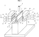
- FIG. 1 shows a liquid injection device 2 structured to inject electrolytic solution into a film exterior battery 1.
- the film exterior battery 1 is exemplarily a lithium ion secondary battery, and includes a generation element 3, a bag-shaped laminate film exterior 4, a cathode tab 5, and an anode tab 6 (see FIG. 2 ).
- the generation element 3 has a rectangle shape, and includes a stack of: a cathode and an anode being electrodes not shown; and a separator not shown which is interposed between the cathode and the anode.
- the bag-shaped laminate film exterior 4 is structured to contain the generation element 3 together with the electrolytic solution.
- Each of the cathode tab 5 and the anode tab 6 is connected to the bag-shaped laminate film exterior 4.
- the bag-shaped laminate film exterior 4 is formed by: superposing two rectangle laminate films to each other such that the cathode tab 5 and the anode tab 6 are led outside respectively from a side 4a and a side 4b parallel with the side 4a; and then heat-welding the side 4a, the side 4b, and a side 4c respectively.
- an opening 7 for the injection of electrolytic solution is formed at an upper side 4d.
- the electrolytic solution is to be injected via the opening 7, into the bag-shaped laminate film exterior 4 containing the generation element 3.
- the liquid injection device 2 includes a presser jig 8, a nozzle 9, a primary seal mechanism 10, a secondary seal mechanism 11, and a heat seal mechanism 12.
- the presser jig 8 is structured to hold the bag-shaped laminate film exterior 4 including the opening 7.
- the nozzle 9 is structured to be used in evacuation of the bag-shaped laminate film exterior 4 and in injection of the electrolytic solution into the bag-shaped laminate film exterior 4.
- the primary seal mechanism 10 is structured to press the opening 7 of the bag-shaped laminate film exterior 4 from both sides of the bag-shaped laminate film exterior 4, with the nozzle 9 inserted in the opening 7.
- the secondary seal mechanism 11 is structured to seal the opening 7 after the liquid injection of electrolytic solution.
- the heat seal mechanism 12 is structured to heat-seal the opening 7 after the liquid injection.
- the presser jig 8 is disposed below the primary seal mechanism 10, the secondary seal mechanism 11, and the heat seal mechanism 12, and is mounted on a presser jig fixing base 13.
- the presser jig 8 exemplarily has a cuboid shape, and includes an insertion hole 14 in which the bag-shaped laminate film exterior 4 is inserted in an attitude that the opening 7 opens upward. As shown in FIG. 1 , in a state that the bag-shaped laminate film exterior 4 is inserted in the insertion hole 14, the bag-shaped laminate film exterior 4 has an upper part projecting upward from an upper surface 8a of the presser jig 8.
- the primary seal mechanism 10, the secondary seal mechanism 11, and the heat seal mechanism 12 are structured to act on the upper part of the bag-shaped laminate film exterior 4.
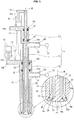
- the nozzle 9 is structured movable upward and downward, and, as shown in FIG. 3 , includes an outer circumferential nozzle 15, an inner circumferential nozzle 16, and a shaft 17.
- the outer circumferential nozzle 15 has a cylindrical tubular shape.
- the inner circumferential nozzle 16 similarly has a cylindrical tubular shape, and is structured expandable telescopically through the outer circumferential nozzle 15.
- the shaft 17 has a cylindrical shape, and is structured expandable telescopically through the inner circumferential nozzle 16.
- the outer circumferential nozzle 15, the inner circumferential nozzle 16, and the shaft 17 have a common central axis M shown as a dash-dot line in FIG. 3 .
- a direction of the central axis M is referred to as "axial direction” for convenience of explanation.
- a lower end side in the axial direction in FIG. 3 is referred to as "first end side in the axial direction”
- an upper end side in the axial direction in FIG. 3 is referred to as "second end side in the axial direction”.
- the outer circumferential nozzle 15 has an inner diameter greater than an outer diameter of the inner circumferential nozzle 16, so as to form an electrolytic solution passage 19 between the outer circumferential nozzle 15 and the inner circumferential nozzle 16 structured to expand and contract through the outer circumferential nozzle 15.
- the electrolytic solution passage 19 has an annular shape, through which the electrolytic solution flows. In a state that the inner circumferential nozzle 16 is expanded, the electrolytic solution passage 19 has an outlet in the first end side in the axial direction, namely, a liquid injection port 20.
- the liquid injection port 20 has an annular shape, and is formed between a tip of the outer circumferential nozzle 15 and an outer periphery of the inner circumferential nozzle 16.
- the inner circumferential nozzle 16 includes in its tip a diameter expansion portion 24 serving as a valve. Accordingly, the liquid injection port 20 is opened and closed due to relative move between the outer circumferential nozzle 15 and the inner circumferential nozzle 16.
- the inner circumferential nozzle 16 includes an electrolytic solution sealing member 26 that has an annular shape and is structured to, in a state that the liquid injection port 20 is closed as shown in FIG. 3 , fluid-tightly seal a gap between a slope 15a of the outer circumferential nozzle 15 and an outer peripheral slope 24a of the inner circumferential nozzle 16.
- the slope 15a is formed in the first end side in the axial direction, as a diameter expansion portion tapered in a conical shape.
- the outer peripheral slope 24a is formed in the diameter expansion portion 24 in the tip of the inner circumferential nozzle 16.
- the electrolytic solution sealing member 26 is made of elastic material such as rubber, and is disposed in an annular groove formed in the outer peripheral slope 24a.
- the electrolytic solution passage 19 extends from the liquid injection port 20 to the second end side in the axial direction, so as to communicate with an electrolytic solution supply passage 21.
- the electrolytic solution supply passage 21 is defined by a projection 15c having a tubular shape projecting from an outer periphery of the outer circumferential nozzle 15.
- the electrolytic solution supply passage 21 is connected to a liquid injection pump 22 serving as a supply source of the electrolytic solution.
- the outer circumferential nozzle 15 includes two annular grooves 15d formed in an inner periphery of the outer circumferential nozzle 15, in the second end side in the axial direction.
- Each of the annular grooves 15d contains a seal member 23 having an annular shape.
- the seal member 23 is made of elastic material such as rubber, and is structured to liquid-tightly seal a gap between the inner periphery of the outer circumferential nozzle 15 and the outer periphery of the inner circumferential nozzle 16 while securing sliding contact therebetween.
- the outer circumferential nozzle 15 further includes an overhang 15b in the second end side in the axial direction.
- the overhang 15b overhangs outward from the outer periphery of the outer circumferential nozzle 15, perpendicularly to the axial direction.
- the overhang 15b is structured to receive a pressing force from a rod 18a of a hydraulic actuator 18.
- the hydraulic actuator 18 is a linear reciprocation actuator connected to a hydraulic pump not shown. The pressing force from the hydraulic actuator 18 is exerted from the second end side in the axial direction, and causes the outer circumferential nozzle 15 to move downward together with the inner circumferential nozzle 16 and the shaft 17.
- the inner circumferential nozzle 16 has the cylindrical tubular shape longer than the outer circumferential nozzle 15.
- the inner circumferential nozzle 16 has an inner diameter greater than an outer diameter of the shaft 17, so as to form a decompression passage 28 between the inner circumferential nozzle 16 and the shaft 17 structured to expand and contract through the inner circumferential nozzle 16.
- the decompression passage 28 has an annular shape, through which gas flows during evacuation for producing a vacuum.
- the decompression passage 28 In a state that the shaft 17 is expanded, the decompression passage 28 has an inlet in the first end side in the axial direction, namely, a suction port 29.
- the suction port 29 has an annular shape, and is formed between the tip of the inner circumferential nozzle 16 and an outer periphery of the shaft 17.
- the shaft 17 includes in its tip a valve 25 having a truncated conical shape. Accordingly, the suction port 29 is opened and closed due to relative move between the inner circumferential nozzle 16 and the shaft 17.
- the shaft 17 includes a gas sealing member 33 that has an annular shape and is structured to, in a state that the suction port 29 is closed as shown in FIG. 3 , gas-tightly seal a gap between an inner peripheral slope 24b of the inner circumferential nozzle 16 and a tapered surface 25a of the shaft 17.
- the inner peripheral slope 24b is formed in the diameter expansion portion 24 of the inner circumferential nozzle 16.
- the tapered surface 25a is formed in the valve 25 in the tip of the shaft 17.
- the gas sealing member 33 is made of rubber similarly to the electrolytic solution sealing member 26, and is disposed in an annular groove formed in the valve 25.
- the decompression passage 28 extends from the suction port 29 to the second end side in the axial direction, so as to be longer than the electrolytic solution passage 19.
- the decompression passage 28 communicates with a gas discharging passage 30 defined by a projection 16 having a tubular shape projecting from the outer periphery of the inner circumferential nozzle 16.
- the gas discharging passage 30 is connected to a vacuum pump 31.
- the inner circumferential nozzle 16 includes two annular grooves 16c formed in an inner periphery of the inner circumferential nozzle 16, in the second end side in the axial direction.
- Each of the annular grooves 16c contains a seal member 32 having an annular shape.
- the seal member 32 is made of elastic material such as rubber, and is structured to gas-tightly seal a gap between the inner periphery of the inner circumferential nozzle 16 and the outer periphery of the shaft 17 so as to suppress an atmosphere from intruding into the decompression passage 28, while securing sliding contact between the inner circumferential nozzle 16 and the shaft 17.
- the inner circumferential nozzle 16 further includes an overhang 16a in the second end side in the axial direction.
- the overhang 16a overhangs outward in the same direction with the overhang 15b of the outer circumferential nozzle 15.
- the overhang 16a is connected to a rod 27a of a hydraulic actuator 27 that is a linear reciprocation actuator supported by the overhang 15b.
- the rod 27a of the hydraulic actuator 27 is driven to cause the inner circumferential nozzle 16 to move in the axial direction, relatively with respect to the outer circumferential nozzle 15.
- the shaft 17 has the cylindrical shape longer than the inner circumferential nozzle 16.
- the shaft 17 includes an overhang 17a formed similarly to the overhang 15b and the overhang 16a, in the second end side in the axial direction.
- the overhang 17a is connected to a rod 34a of a hydraulic actuator 34 that is a linear reciprocation actuator supported by the overhang 16a.
- the rod 34a of the hydraulic actuator 34 is driven to cause the shaft 17 to move in the axial direction, relatively with respect to the inner circumferential nozzle 16.
- the primary seal mechanism 10 is disposed below the heat seal mechanism 12 as shown in FIG. 1 , and is structured to establish sealing around the outer circumferential nozzle 15 by pressing the both sides of the bag-shaped laminate film exterior 4 in which the nozzle 9 is inserted.
- the primary seal mechanism 10 includes a pair of elastic bodies 35 and 36 structured to establish the sealing around the outer circumferential nozzle 15, and includes a pair of holders 37 and 38 structured to respectively hold the pair of elastic bodies 35 and 36.
- the elastic body 35 is disposed in a first side with respect to the bag-shaped laminate film exterior 4 (i.e. a right side in FIG. 4 ), and is structured to establish the sealing around the outer circumferential nozzle 15 along a seal line L1 (see FIG. 2 ) crossing the nozzle 9, by pressing the opening 7 together with the nozzle 9 from the both sides of the bag-shaped laminate film exterior 4 in cooperation with the elastic body 36.
- the elastic body 35 is made of rubber being elastic material, such as fluoro rubber.
- the elastic body 35 has a shape of slender rod with a circular cross section, and has a length enough to seal the opening 7 at the upper side 4d of the bag-shaped laminate film exterior 4. As shown in FIG.
- the elastic body 35 includes at its center a curve portion 39 having a semicircular shape curving to fit with the outer periphery of the outer circumferential nozzle 15 of the nozzle 9.
- the curve portion 39 has a size to appropriately press the outer circumferential nozzle 15 and a part of the bag-shaped laminate film exterior 4 around the outer circumferential nozzle 15, upon pressing the opening 7 together with the outer circumferential nozzle 15 from outside of the bag-shaped laminate film exterior 4.
- the holder 37 is exemplarily made of metal, and has a substantially U-shaped cross section as shown in FIG. 4 .
- the holder 37 includes a bottom wall 37a rising vertically, and a pair of side walls 37b, 37b extending horizontally from the bottom wall 37a, parallel with each other.
- the bottom wall 37a and the pair of side walls 37b, 37b define a recessed groove 37c formed to contain the elastic body 35.
- the elastic body 35 is heat-welded or glued to the holder 37.
- each of the pair of side walls 37b, 37b includes a cut-out portion 37d shaped in conformance with the curve portion 39 of the elastic body 35 as shown in FIG. 6 , so as to avoid interference with the outer circumferential nozzle 15.
- the elastic body 36 is disposed in a second side with respect to the bag-shaped laminate film exterior 4 (i.e. a left side in FIG. 4 ).
- the elastic body 36 is made of rubber harder than that for the elastic body 35, such as silicone rubber, and has a shape of flat sheet.
- the holder 38 is exemplarily made of metal, and has a cuboid shape as shown in FIG. 4 onto which the elastic body 36 is heat-welded or glued.
- the primary seal mechanism 10 is disposed along the seal line L1 shown in FIG. 2 , and includes hydraulic actuators 40 and 50.
- the hydraulic actuators 40 and 50 are structured to cause the elastic bodies 35 and 36 to linearly reciprocate independently of each other, with respect to the bag-shaped laminate film exterior 4.
- the hydraulic actuator 40 includes a rod 40a connected to the bottom wall 37a of the holder 37
- the hydraulic actuator 50 includes a rod 50a connected to the holder 38.
- the hydraulic actuators 40 and 50 are structured to work in coordination with each other so as to open and close the elastic bodies 35 and 36 disposed opposite to each other across the opening 7.
- the primary seal mechanism 10 corresponds to a first seal mechanism in the claims.
- the secondary seal mechanism 11 is disposed nearer to the generation element 3 than the primary seal mechanism 10, namely along the seal line L2 shown in FIG. 2 .
- the secondary seal mechanism 11 is structured to prevent leakage of the electrolytic solution and intrusion of the atmosphere, by sealing the opening 7 without interposing the nozzle 9 after a process for the liquid injection.
- the secondary seal mechanism 11 includes a pair of elastic bodies 41 and 42 and a pair of holders 43 and 44 structured to hold the pair of elastic bodies 41 and 42.
- the elastic body 41 is disposed in the first side with respect to the bag-shaped laminate film exterior 4 (i.e. the right side in FIG. 4 ) and below the elastic body 35, and is structured to seal the opening 7 along the seal line L2 (see FIG. 2 ) by pressing the opening 7 from the both sides of the bag-shaped laminate film exterior 4 in cooperation with the elastic body 42.
- the elastic body 41 is made of rubber same with the elastic body 35, such as the fluoro rubber, and has a hardness same with the elastic body 35.
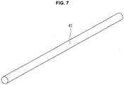
- the elastic body 41 has a slender cylindrical shape, and has a length enough to seal the opening 7 at the upper side 4d of the bag-shaped laminate film exterior 4, similarly to the elastic body 35.
- the holder 43 is exemplarily made of metal, and, as shown in FIG. 4 , has a substantially U-shaped cross section.
- the holder 43 is configured similarly to the holder 37, and includes a bottom wall 43a, a pair of side walls 43b, 43b, and a recessed groove 43c defined by the bottom wall 43a and the pair of side walls 43b, 43b.
- the recessed groove 43c contains the elastic body 41 that is heat-welded or glued to the recessed groove 43c.
- the elastic body 42 is made of rubber same with the elastic body 36, and has a shape of flat sheet.
- the holder 44 has a cuboid shape similar to the holder 38, onto which the elastic body 42 is heat-welded or glued.
- the secondary seal mechanism 11 includes hydraulic actuators 45 and 51.
- the hydraulic actuators 45 and 51 respectively include rods 45a and 51a (see FIG. 4 ) structured to open and close the elastic bodies 41 and 42 disposed opposite to each other across the opening 7.
- the secondary seal mechanism 11 corresponds to a second seal mechanism in the claims.
- the heat seal mechanism 12 includes a pair of seal heaters 46, 46 structured to heat-seal the opening 7 of the bag-shaped laminate film exterior 4 after the injection of electrolytic solution.
- the pair of seal heaters 46, 46 are configured substantially same with each other, and are disposed above the primary seal mechanism 10 as shown in FIG. 1 .
- each of the pair of seal heaters 46, 46 has a block-like shape, and is made of metal sufficient in thermal conductivity, and internally includes a heat source such as a hot wire.
- each of the pair of seal heaters 46, 46 is connected to an actuator not shown, in order to open and close interposing the opening 7.
- the tip of the nozzle 9 is caused to move downward due to action of the hydraulic actuator 18 and is inserted into the opening 7, with the bag-shaped laminate film exterior 4 inserted in the insertion hole 14 in the attitude that the opening 7 opens upward as shown in FIG. 1 .
- the pair of elastic bodies 35 and 36 are caused to approach each other due to action of the hydraulic actuators 40 and 50, so as to press from the both sides the bag-shaped laminate film exterior 4 in which the nozzle 9 is inserted.
- the elastic bodies 35 and 36 establish the sealing around the outer circumferential nozzle 15 together with the bag-shaped laminate film exterior 4.
- FIGs. 8A, 8B, and 8C the nozzle 9 is already inserted in the bag-shaped laminate film exterior 4.
- Each broken line in the drawings represents the pair of elastic bodies 35 and 36 pressing the bag-shaped laminate film exterior 4 from the both sides at a position of the seal line L1 (see FIG. 2 ) with the outer circumferential nozzle 15 inserted in the bag-shaped laminate film exterior 4.
- a dash-dot line represents the pair of elastic bodies 41 and 42 sealing the bag-shaped laminate film exterior 4 at a position of the seal line L2 (see FIG. 2 ).
- the inner circumferential nozzle 16 is caused to project to the first end side in the axial direction with respect to the outer circumferential nozzle 15, due to action of the hydraulic actuator 27.
- the annular liquid injection port 20 between the tip of the outer circumferential nozzle 15 and the outer periphery of the inner circumferential nozzle 16 is open.
- the diameter expansion portion 24 of the inner circumferential nozzle 16 is at a position protuberant to the first end side in the axial direction with respect to the liquid injection port 20.
- the shaft 17 is caused to project to the first end side in the axial direction with respect to the inner circumferential nozzle 16.
- the annular suction port 29 between the diameter expansion portion 24 and the outer periphery of the 17 is open.
- the valve 25 is at a position protuberant to the first end side in the axial direction with respect to the diameter expansion portion 24.
- the suction port 29 at the tip of the inner circumferential nozzle 16 opens in the bag-shaped laminate film exterior 4, at a position protuberant to the first end side in the axial direction with respect to the liquid injection port 20 of the outer circumferential nozzle 15.
- the valve 25 at the protuberant position is in a vicinity of an edge of the generation element 3.
- the vacuum pump 31 evacuates gas inside the bag-shaped laminate film exterior 4, i.e. produces a vacuum in the bag-shaped laminate film exterior 4, through the suction port 29 and the decompression passage 28.
- the shaft 17 is retracted upward with respect to the inner circumferential nozzle 16, due to action of the hydraulic actuator 34.
- the suction port 29 of the inner circumferential nozzle 16 is closed from outside by the valve 25, and the gap between the tapered surface 25a and the inner peripheral slope 24b is gas-tightly sealed by the gas sealing member 33.
- the electrolytic solution is injected into the bag-shaped laminate film exterior 4 through the electrolytic solution passage 19 and the liquid injection port 20, by operating the liquid injection pump 22 with the suction port 29 closed by the valve 25.
- the inner circumferential nozzle 16 is retracted upward together with the shaft 17 from the axial position shown in FIG. 8B , due to action of the hydraulic actuator 27.
- the retraction of the inner circumferential nozzle 16 causes the liquid injection port 20 of the outer circumferential nozzle 15 to be closed by the diameter expansion portion 24 of the inner circumferential nozzle 16 as shown in FIG. 8C , and causes the gap between the slope 15a and the outer peripheral slope 24a to be liquid-tightly sealed by the electrolytic solution sealing member 26.
- a heat seal process is implemented to heat the bag-shaped laminate film exterior 4 from the both sides at a position above the seal line L1 shown in FIG. 2 , by the pair of seal heaters 46, 46. This causes the bag-shaped laminate film exterior 4 to be heat-sealed along the upper side 4d shown in FIG. 2 .
- the present embodiment is configured such that during the evacuation in the bag-shaped laminate film exterior 4, the suction port 29 in the tip of the inner circumferential nozzle 16 is open inside the bag-shaped laminate film exterior 4, at the position protuberant in the axial direction with respect to the liquid injection port 20 of the outer circumferential nozzle 15.
- the inner circumferential nozzle 16 is inserted in the bag-shaped laminate film exterior 4 deeply to reach the vicinity of the generation element 3 such that the suction port 29 is positioned in the vicinity of the edge of the generation element 3.
- a nozzle is formed as a single pipe and is deeply inserted into a bag-shaped laminate film exterior upon evacuation, the bag-shaped laminate film exterior may be deteriorate in sealability because the nozzle needs to be extracted through a long distance after the evacuation.
- the outer circumferential nozzle 15, around which the seal is established by the elastic bodies 35 and 36, does not need to be deeply inserted into the bag-shaped laminate film exterior 4. This serves to suppress the bag-shaped laminate film exterior 4 from deteriorating in sealability due to the retraction of the nozzle 9.
- the suction port 29 of the inner circumferential nozzle 16 is opened and closed by the valve 25 disposed in the tip of the shaft 17, wherein the suction port 29 is closed by the valve 25 during the liquid injection. This serves to certainly insulate the decompression passage 28 from the electrolytic solution passage 19 during the liquid injection.
- the liquid injection device 2 includes two seal mechanisms: the primary seal mechanism 10 and the secondary seal mechanism 11.
- the nozzle 9 is extracted from the opening 7 of the bag-shaped laminate film exterior 4 subsequently to release of the seal of the pair of elastic bodies 35 and 36 while maintaining the pair of elastic bodies 41 and 42 sealing the opening 7. This serves to secure the bag-shaped laminate film exterior 4 in sealability by the pair of elastic bodies 41 and 42, and thereby suppress the bag-shaped laminate film exterior 4 from deteriorating in sealability due to the extraction of the nozzle 9.
- the elastic bodies 35 and 36 are configured to establish sealing around only one nozzle, i.e. around the outer circumferential nozzle 15. This serves to facilitate extracting the outer circumferential nozzle 15 in comparison with a case of extracting one liquid injection nozzle and one evacuation nozzle around which sealing is established by a pair of elastic bodies.
- the present invention may alternatively employ a bag-shaped film exterior formed by folding one rectangle laminate film in two and then respectively heat-welding two sides perpendicular to a folded side of the bag-shaped film exterior.
- the present invention may be applied in order to alternatively employ a film exterior battery 1 structured such that the cathode tab 5 and the anode tab 6 are led outside from a common one side.
- the bag-shaped laminate film exterior 4 may be disposed in another attitude.
Landscapes
- Chemical & Material Sciences (AREA)
- Chemical Kinetics & Catalysis (AREA)
- Electrochemistry (AREA)
- General Chemical & Material Sciences (AREA)
- Engineering & Computer Science (AREA)
- Manufacturing & Machinery (AREA)
- Filling, Topping-Up Batteries (AREA)
- Bag Frames (AREA)
Abstract


Description
- The present invention relates to a liquid injection device including a nozzle to be inserted in a bag-shaped laminate film exterior, wherein gas inside the bag-shaped laminate film exterior is evacuated through the nozzle.
-
Patent Document 1 discloses a liquid injection device including an evacuation nozzle to be inserted in an opening of a laminate sheet bag containing a generation element, for producing a vacuum in the laminate sheet bag. - The liquid injection device according to
Patent Document 1 includes the evacuation nozzle separately from a liquid injection nozzle. These nozzles are inserted in the opening of the laminate sheet bag. - In case that the evacuation is implemented with a tip of the evacuation nozzle relatively apart from the generation element, the liquid injection device may cause insufficient evacuation in the laminate sheet bag due to adhesion between laminate sheets in a region between the evacuation nozzle tip and the generation element.
- Alternatively, in case that the evacuation is implemented with the evacuation nozzle tip inserted deeply to reach a vicinity of the generation element, the laminate sheet bag may deteriorate in sealability because the evacuation nozzle after the evacuation needs to be extracted through a long distance with the evacuated nozzle pressed by a pair of seal blocks.
- In view of the foregoing problem, it is desirable to provide a liquid injection device structured to certainly evacuate gas inside a bag-shaped film exterior.
- Patent Document 1:
JP 2012-64468 A - According to one aspect of the present invention, an inner circumferential nozzle is structured to have a suction port open at a position protuberant with respect to a liquid injection port of an outer circumferential nozzle in an axial direction of the outer circumferential nozzle, in a state that the inner circumferential nozzle is expanded.
- According to one aspect of the present invention, the inner circumferential nozzle is expanded inside a bag-shaped film exterior. This serves to certainly evacuate gas inside the bag-shaped film exterior.
-
-
FIG. 1 is a perspective view of a liquid injection device according to an embodiment. -
FIG. 2 is an illustrative view of a bag-shaped laminate film exterior with a nozzle inserted therein. -
FIG. 3 is a longitudinal sectional view of the nozzle along its axis. -
FIG. 4 is an illustrative view of the liquid injection device viewed from a front side ofFIG. 1 . -
FIG. 5 is a perspective view of an elastic body employed in a primary seal mechanism. -
FIG. 6 is a cross sectional view of the liquid injection device along a line A-A shown inFIG. 1 . -
FIG. 7 is a perspective view of an elastic body employed in a secondary seal mechanism. -
FIG. 8A is an illustrative view of a process for evacuation in the bag-shaped laminate film exterior. -
FIG. 8B is an illustrative view of a process for liquid injection into the bag-shaped laminate film exterior. -
FIG. 8C is an illustrative view of a process for seal of the bag-shaped laminate film exterior after the liquid injection. - The following describes an embodiment of the present invention, with reference to the drawings.
-
FIG. 1 shows aliquid injection device 2 structured to inject electrolytic solution into a filmexterior battery 1. The filmexterior battery 1 is exemplarily a lithium ion secondary battery, and includes ageneration element 3, a bag-shaped laminate film exterior 4, acathode tab 5, and an anode tab 6 (seeFIG. 2 ). Thegeneration element 3 has a rectangle shape, and includes a stack of: a cathode and an anode being electrodes not shown; and a separator not shown which is interposed between the cathode and the anode. The bag-shapedlaminate film exterior 4 is structured to contain thegeneration element 3 together with the electrolytic solution. Each of thecathode tab 5 and theanode tab 6 is connected to the bag-shapedlaminate film exterior 4. - The following further describes the bag-shaped
laminate film exterior 4 to which liquid injection is implemented. As shown inFIG. 2 , the bag-shaped laminate film exterior 4 is formed by: superposing two rectangle laminate films to each other such that thecathode tab 5 and theanode tab 6 are led outside respectively from aside 4a and aside 4b parallel with theside 4a; and then heat-welding theside 4a, theside 4b, and aside 4c respectively. In this state that thesides opening 7 for the injection of electrolytic solution is formed at anupper side 4d. The electrolytic solution is to be injected via theopening 7, into the bag-shapedlaminate film exterior 4 containing thegeneration element 3. - The
liquid injection device 2 includes apresser jig 8, anozzle 9, aprimary seal mechanism 10, asecondary seal mechanism 11, and aheat seal mechanism 12. Thepresser jig 8 is structured to hold the bag-shapedlaminate film exterior 4 including the opening 7. Thenozzle 9 is structured to be used in evacuation of the bag-shapedlaminate film exterior 4 and in injection of the electrolytic solution into the bag-shapedlaminate film exterior 4. Theprimary seal mechanism 10 is structured to press the opening 7 of the bag-shapedlaminate film exterior 4 from both sides of the bag-shapedlaminate film exterior 4, with thenozzle 9 inserted in theopening 7. Thesecondary seal mechanism 11 is structured to seal the opening 7 after the liquid injection of electrolytic solution. Theheat seal mechanism 12 is structured to heat-seal the opening 7 after the liquid injection. - The
presser jig 8 is disposed below theprimary seal mechanism 10, thesecondary seal mechanism 11, and theheat seal mechanism 12, and is mounted on a presserjig fixing base 13. Thepresser jig 8 exemplarily has a cuboid shape, and includes aninsertion hole 14 in which the bag-shapedlaminate film exterior 4 is inserted in an attitude that the opening 7 opens upward. As shown inFIG. 1 , in a state that the bag-shaped laminate film exterior 4 is inserted in theinsertion hole 14, the bag-shapedlaminate film exterior 4 has an upper part projecting upward from anupper surface 8a of thepresser jig 8. Theprimary seal mechanism 10, thesecondary seal mechanism 11, and theheat seal mechanism 12 are structured to act on the upper part of the bag-shapedlaminate film exterior 4. - The
nozzle 9 is structured movable upward and downward, and, as shown inFIG. 3 , includes an outercircumferential nozzle 15, an innercircumferential nozzle 16, and ashaft 17. The outercircumferential nozzle 15 has a cylindrical tubular shape. The innercircumferential nozzle 16 similarly has a cylindrical tubular shape, and is structured expandable telescopically through the outercircumferential nozzle 15. Theshaft 17 has a cylindrical shape, and is structured expandable telescopically through the innercircumferential nozzle 16. - The outer
circumferential nozzle 15, the innercircumferential nozzle 16, and theshaft 17 have a common central axis M shown as a dash-dot line inFIG. 3 . In the following description, a direction of the central axis M is referred to as "axial direction" for convenience of explanation. Furthermore, a lower end side in the axial direction inFIG. 3 is referred to as "first end side in the axial direction", and an upper end side in the axial direction inFIG. 3 is referred to as "second end side in the axial direction". - The outer
circumferential nozzle 15 has an inner diameter greater than an outer diameter of the innercircumferential nozzle 16, so as to form anelectrolytic solution passage 19 between the outercircumferential nozzle 15 and the innercircumferential nozzle 16 structured to expand and contract through the outercircumferential nozzle 15. Theelectrolytic solution passage 19 has an annular shape, through which the electrolytic solution flows. In a state that the innercircumferential nozzle 16 is expanded, theelectrolytic solution passage 19 has an outlet in the first end side in the axial direction, namely, aliquid injection port 20. Theliquid injection port 20 has an annular shape, and is formed between a tip of the outercircumferential nozzle 15 and an outer periphery of the innercircumferential nozzle 16. The innercircumferential nozzle 16 includes in its tip adiameter expansion portion 24 serving as a valve. Accordingly, theliquid injection port 20 is opened and closed due to relative move between the outercircumferential nozzle 15 and the innercircumferential nozzle 16. The innercircumferential nozzle 16 includes an electrolyticsolution sealing member 26 that has an annular shape and is structured to, in a state that theliquid injection port 20 is closed as shown inFIG. 3 , fluid-tightly seal a gap between aslope 15a of the outercircumferential nozzle 15 and an outerperipheral slope 24a of the innercircumferential nozzle 16. Theslope 15a is formed in the first end side in the axial direction, as a diameter expansion portion tapered in a conical shape. The outerperipheral slope 24a is formed in thediameter expansion portion 24 in the tip of the innercircumferential nozzle 16. The electrolyticsolution sealing member 26 is made of elastic material such as rubber, and is disposed in an annular groove formed in the outerperipheral slope 24a. - The
electrolytic solution passage 19 extends from theliquid injection port 20 to the second end side in the axial direction, so as to communicate with an electrolyticsolution supply passage 21. The electrolyticsolution supply passage 21 is defined by aprojection 15c having a tubular shape projecting from an outer periphery of the outercircumferential nozzle 15. The electrolyticsolution supply passage 21 is connected to a liquid injection pump 22 serving as a supply source of the electrolytic solution. - The outer
circumferential nozzle 15 includes twoannular grooves 15d formed in an inner periphery of the outercircumferential nozzle 15, in the second end side in the axial direction. Each of theannular grooves 15d contains aseal member 23 having an annular shape. Theseal member 23 is made of elastic material such as rubber, and is structured to liquid-tightly seal a gap between the inner periphery of the outercircumferential nozzle 15 and the outer periphery of the innercircumferential nozzle 16 while securing sliding contact therebetween. - The outer
circumferential nozzle 15 further includes anoverhang 15b in the second end side in the axial direction. Theoverhang 15b overhangs outward from the outer periphery of the outercircumferential nozzle 15, perpendicularly to the axial direction. Theoverhang 15b is structured to receive a pressing force from arod 18a of ahydraulic actuator 18. Thehydraulic actuator 18 is a linear reciprocation actuator connected to a hydraulic pump not shown. The pressing force from thehydraulic actuator 18 is exerted from the second end side in the axial direction, and causes the outercircumferential nozzle 15 to move downward together with the innercircumferential nozzle 16 and theshaft 17. - The inner
circumferential nozzle 16 has the cylindrical tubular shape longer than the outercircumferential nozzle 15. The innercircumferential nozzle 16 has an inner diameter greater than an outer diameter of theshaft 17, so as to form adecompression passage 28 between the innercircumferential nozzle 16 and theshaft 17 structured to expand and contract through the innercircumferential nozzle 16. Thedecompression passage 28 has an annular shape, through which gas flows during evacuation for producing a vacuum. In a state that theshaft 17 is expanded, thedecompression passage 28 has an inlet in the first end side in the axial direction, namely, asuction port 29. Thesuction port 29 has an annular shape, and is formed between the tip of the innercircumferential nozzle 16 and an outer periphery of theshaft 17. Theshaft 17 includes in its tip avalve 25 having a truncated conical shape. Accordingly, thesuction port 29 is opened and closed due to relative move between the innercircumferential nozzle 16 and theshaft 17. Theshaft 17 includes agas sealing member 33 that has an annular shape and is structured to, in a state that thesuction port 29 is closed as shown inFIG. 3 , gas-tightly seal a gap between an innerperipheral slope 24b of the innercircumferential nozzle 16 and atapered surface 25a of theshaft 17. The innerperipheral slope 24b is formed in thediameter expansion portion 24 of the innercircumferential nozzle 16. Thetapered surface 25a is formed in thevalve 25 in the tip of theshaft 17. Thegas sealing member 33 is made of rubber similarly to the electrolyticsolution sealing member 26, and is disposed in an annular groove formed in thevalve 25. - The
decompression passage 28 extends from thesuction port 29 to the second end side in the axial direction, so as to be longer than theelectrolytic solution passage 19. Thedecompression passage 28 communicates with agas discharging passage 30 defined by aprojection 16 having a tubular shape projecting from the outer periphery of the innercircumferential nozzle 16. Thegas discharging passage 30 is connected to avacuum pump 31. - Similarly to the outer
circumferential nozzle 15, the innercircumferential nozzle 16 includes twoannular grooves 16c formed in an inner periphery of the innercircumferential nozzle 16, in the second end side in the axial direction. Each of theannular grooves 16c contains aseal member 32 having an annular shape. Theseal member 32 is made of elastic material such as rubber, and is structured to gas-tightly seal a gap between the inner periphery of the innercircumferential nozzle 16 and the outer periphery of theshaft 17 so as to suppress an atmosphere from intruding into thedecompression passage 28, while securing sliding contact between the innercircumferential nozzle 16 and theshaft 17. - The inner
circumferential nozzle 16 further includes anoverhang 16a in the second end side in the axial direction. Theoverhang 16a overhangs outward in the same direction with theoverhang 15b of the outercircumferential nozzle 15. Theoverhang 16a is connected to arod 27a of ahydraulic actuator 27 that is a linear reciprocation actuator supported by theoverhang 15b. Therod 27a of thehydraulic actuator 27 is driven to cause the innercircumferential nozzle 16 to move in the axial direction, relatively with respect to the outercircumferential nozzle 15. - The
shaft 17 has the cylindrical shape longer than the innercircumferential nozzle 16. Theshaft 17 includes anoverhang 17a formed similarly to theoverhang 15b and theoverhang 16a, in the second end side in the axial direction. Theoverhang 17a is connected to arod 34a of ahydraulic actuator 34 that is a linear reciprocation actuator supported by theoverhang 16a. Therod 34a of thehydraulic actuator 34 is driven to cause theshaft 17 to move in the axial direction, relatively with respect to the innercircumferential nozzle 16. - The
primary seal mechanism 10 is disposed below theheat seal mechanism 12 as shown inFIG. 1 , and is structured to establish sealing around the outercircumferential nozzle 15 by pressing the both sides of the bag-shapedlaminate film exterior 4 in which thenozzle 9 is inserted. Theprimary seal mechanism 10 includes a pair ofelastic bodies circumferential nozzle 15, and includes a pair ofholders elastic bodies - As shown in
FIG. 4 , theelastic body 35 is disposed in a first side with respect to the bag-shaped laminate film exterior 4 (i.e. a right side inFIG. 4 ), and is structured to establish the sealing around the outercircumferential nozzle 15 along a seal line L1 (seeFIG. 2 ) crossing thenozzle 9, by pressing theopening 7 together with thenozzle 9 from the both sides of the bag-shapedlaminate film exterior 4 in cooperation with theelastic body 36. Theelastic body 35 is made of rubber being elastic material, such as fluoro rubber. Theelastic body 35 has a shape of slender rod with a circular cross section, and has a length enough to seal theopening 7 at theupper side 4d of the bag-shapedlaminate film exterior 4. As shown inFIG. 5 , theelastic body 35 includes at its center acurve portion 39 having a semicircular shape curving to fit with the outer periphery of the outercircumferential nozzle 15 of thenozzle 9. As shown inFIG. 6 , thecurve portion 39 has a size to appropriately press the outercircumferential nozzle 15 and a part of the bag-shapedlaminate film exterior 4 around the outercircumferential nozzle 15, upon pressing theopening 7 together with the outercircumferential nozzle 15 from outside of the bag-shapedlaminate film exterior 4. - The
holder 37 is exemplarily made of metal, and has a substantially U-shaped cross section as shown inFIG. 4 . Theholder 37 includes abottom wall 37a rising vertically, and a pair ofside walls bottom wall 37a, parallel with each other. Thebottom wall 37a and the pair ofside walls groove 37c formed to contain theelastic body 35. Theelastic body 35 is heat-welded or glued to theholder 37. In addition, each of the pair ofside walls portion 37d shaped in conformance with thecurve portion 39 of theelastic body 35 as shown inFIG. 6 , so as to avoid interference with the outercircumferential nozzle 15. - As shown in in
FIG. 4 , theelastic body 36 is disposed in a second side with respect to the bag-shaped laminate film exterior 4 (i.e. a left side inFIG. 4 ). Theelastic body 36 is made of rubber harder than that for theelastic body 35, such as silicone rubber, and has a shape of flat sheet. - The
holder 38 is exemplarily made of metal, and has a cuboid shape as shown inFIG. 4 onto which theelastic body 36 is heat-welded or glued. - As shown in
FIG. 1 , theprimary seal mechanism 10 is disposed along the seal line L1 shown inFIG. 2 , and includeshydraulic actuators hydraulic actuators elastic bodies laminate film exterior 4. As shown inFIG. 4 , thehydraulic actuator 40 includes arod 40a connected to thebottom wall 37a of theholder 37, and thehydraulic actuator 50 includes arod 50a connected to theholder 38. Thehydraulic actuators elastic bodies opening 7. - The
primary seal mechanism 10 corresponds to a first seal mechanism in the claims. - The
secondary seal mechanism 11 is disposed nearer to thegeneration element 3 than theprimary seal mechanism 10, namely along the seal line L2 shown inFIG. 2 . Thesecondary seal mechanism 11 is structured to prevent leakage of the electrolytic solution and intrusion of the atmosphere, by sealing theopening 7 without interposing thenozzle 9 after a process for the liquid injection. Thesecondary seal mechanism 11 includes a pair ofelastic bodies holders elastic bodies - As shown in
FIG. 4 , theelastic body 41 is disposed in the first side with respect to the bag-shaped laminate film exterior 4 (i.e. the right side inFIG. 4 ) and below theelastic body 35, and is structured to seal theopening 7 along the seal line L2 (seeFIG. 2 ) by pressing theopening 7 from the both sides of the bag-shapedlaminate film exterior 4 in cooperation with theelastic body 42. Theelastic body 41 is made of rubber same with theelastic body 35, such as the fluoro rubber, and has a hardness same with theelastic body 35. As shown inFIG. 7 , theelastic body 41 has a slender cylindrical shape, and has a length enough to seal theopening 7 at theupper side 4d of the bag-shapedlaminate film exterior 4, similarly to theelastic body 35. - The
holder 43 is exemplarily made of metal, and, as shown inFIG. 4 , has a substantially U-shaped cross section. Theholder 43 is configured similarly to theholder 37, and includes abottom wall 43a, a pair ofside walls groove 43c defined by thebottom wall 43a and the pair ofside walls groove 43c contains theelastic body 41 that is heat-welded or glued to the recessedgroove 43c. - The
elastic body 42 is made of rubber same with theelastic body 36, and has a shape of flat sheet. - The
holder 44 has a cuboid shape similar to theholder 38, onto which theelastic body 42 is heat-welded or glued. - As shown in
FIG. 1 , thesecondary seal mechanism 11 includeshydraulic actuators hydraulic actuators rods FIG. 4 ) structured to open and close theelastic bodies opening 7. - The
secondary seal mechanism 11 corresponds to a second seal mechanism in the claims. - The
heat seal mechanism 12 includes a pair ofseal heaters opening 7 of the bag-shapedlaminate film exterior 4 after the injection of electrolytic solution. The pair ofseal heaters primary seal mechanism 10 as shown inFIG. 1 . For example, each of the pair ofseal heaters seal heaters opening 7. - Upon use of thus-configured
liquid injection device 2, the tip of thenozzle 9 is caused to move downward due to action of thehydraulic actuator 18 and is inserted into theopening 7, with the bag-shapedlaminate film exterior 4 inserted in theinsertion hole 14 in the attitude that theopening 7 opens upward as shown inFIG. 1 . Then, the pair ofelastic bodies hydraulic actuators laminate film exterior 4 in which thenozzle 9 is inserted. Thus, theelastic bodies circumferential nozzle 15 together with the bag-shapedlaminate film exterior 4. - Next, the following describes an evacuation process, a liquid injection process, and a seal process of the bag-shaped
laminate film exterior 4, with reference toFIGs. 8A, 8B, and 8C . - In
FIGs. 8A, 8B, and 8C , thenozzle 9 is already inserted in the bag-shapedlaminate film exterior 4. Each broken line in the drawings represents the pair ofelastic bodies laminate film exterior 4 from the both sides at a position of the seal line L1 (seeFIG. 2 ) with the outercircumferential nozzle 15 inserted in the bag-shapedlaminate film exterior 4. InFIG. 8C , a dash-dot line represents the pair ofelastic bodies laminate film exterior 4 at a position of the seal line L2 (seeFIG. 2 ). - As shown in
FIG. 8A , in the evacuation process, the innercircumferential nozzle 16 is caused to project to the first end side in the axial direction with respect to the outercircumferential nozzle 15, due to action of thehydraulic actuator 27. After the innercircumferential nozzle 16 has projected, as shown inFIG. 8A , the annularliquid injection port 20 between the tip of the outercircumferential nozzle 15 and the outer periphery of the innercircumferential nozzle 16 is open. Furthermore, thediameter expansion portion 24 of the innercircumferential nozzle 16 is at a position protuberant to the first end side in the axial direction with respect to theliquid injection port 20. - Then, while maintaining the
diameter expansion portion 24 protuberant to the first end side in the axial direction, theshaft 17 is caused to project to the first end side in the axial direction with respect to the innercircumferential nozzle 16. After theshaft 17 has projected, theannular suction port 29 between thediameter expansion portion 24 and the outer periphery of the 17 is open. Furthermore, thevalve 25 is at a position protuberant to the first end side in the axial direction with respect to thediameter expansion portion 24. Thus, thesuction port 29 at the tip of the innercircumferential nozzle 16 opens in the bag-shapedlaminate film exterior 4, at a position protuberant to the first end side in the axial direction with respect to theliquid injection port 20 of the outercircumferential nozzle 15. In addition, thevalve 25 at the protuberant position is in a vicinity of an edge of thegeneration element 3. - Next, as shown by arrows G in
FIG. 8A , thevacuum pump 31 evacuates gas inside the bag-shapedlaminate film exterior 4, i.e. produces a vacuum in the bag-shapedlaminate film exterior 4, through thesuction port 29 and thedecompression passage 28. - As shown in
FIG. 8B , in the liquid injection process subsequent to the evacuation process, theshaft 17 is retracted upward with respect to the innercircumferential nozzle 16, due to action of thehydraulic actuator 34. Thus, as shown inFIG. 8B , thesuction port 29 of the innercircumferential nozzle 16 is closed from outside by thevalve 25, and the gap between thetapered surface 25a and the innerperipheral slope 24b is gas-tightly sealed by thegas sealing member 33. - Then, as shown by arrows L in
FIG. 8B , the electrolytic solution is injected into the bag-shapedlaminate film exterior 4 through theelectrolytic solution passage 19 and theliquid injection port 20, by operating the liquid injection pump 22 with thesuction port 29 closed by thevalve 25. - As shown in
FIG. 8C , in the seal process subsequent to the liquid injection process, the innercircumferential nozzle 16 is retracted upward together with theshaft 17 from the axial position shown inFIG. 8B , due to action of thehydraulic actuator 27. The retraction of the innercircumferential nozzle 16 causes theliquid injection port 20 of the outercircumferential nozzle 15 to be closed by thediameter expansion portion 24 of the innercircumferential nozzle 16 as shown inFIG. 8C , and causes the gap between theslope 15a and the outerperipheral slope 24a to be liquid-tightly sealed by the electrolyticsolution sealing member 26. - Then, with the
liquid injection port 20 and thesuction port 29 closed, theopening 7 of the bag-shapedlaminate film exterior 4 is sealed at the position of the seal line L2 by the pair ofelastic bodies - Next, while maintaining the pair of
elastic bodies opening 7 of the bag-shapedlaminate film exterior 4, the pair ofelastic bodies laminate film exterior 4, and subsequently thenozzle 9 is extracted from theopening 7. - Subsequently to the seal process shown in
FIG. 8C , a heat seal process is implemented to heat the bag-shapedlaminate film exterior 4 from the both sides at a position above the seal line L1 shown inFIG. 2 , by the pair ofseal heaters laminate film exterior 4 to be heat-sealed along theupper side 4d shown inFIG. 2 . - As described above, the present embodiment is configured such that during the evacuation in the bag-shaped
laminate film exterior 4, thesuction port 29 in the tip of the innercircumferential nozzle 16 is open inside the bag-shapedlaminate film exterior 4, at the position protuberant in the axial direction with respect to theliquid injection port 20 of the outercircumferential nozzle 15. In other words, the innercircumferential nozzle 16 is inserted in the bag-shapedlaminate film exterior 4 deeply to reach the vicinity of thegeneration element 3 such that thesuction port 29 is positioned in the vicinity of the edge of thegeneration element 3. Since upon the evacuation the innercircumferential nozzle 16 is expanded inside of the bag-shapedlaminate film exterior 4 such that thesuction port 29 is positioned in the vicinity of the edge of thegeneration element 3, the evacuation in the bag-shapedlaminate film exterior 4 is certainly performed via thesuction port 29. - If a nozzle is formed as a single pipe and is deeply inserted into a bag-shaped laminate film exterior upon evacuation, the bag-shaped laminate film exterior may be deteriorate in sealability because the nozzle needs to be extracted through a long distance after the evacuation.
- In contrast, according to the present embodiment, the outer
circumferential nozzle 15, around which the seal is established by theelastic bodies laminate film exterior 4. This serves to suppress the bag-shapedlaminate film exterior 4 from deteriorating in sealability due to the retraction of thenozzle 9. - Moreover, according to the present embodiment, the
suction port 29 of the innercircumferential nozzle 16 is opened and closed by thevalve 25 disposed in the tip of theshaft 17, wherein thesuction port 29 is closed by thevalve 25 during the liquid injection. This serves to certainly insulate thedecompression passage 28 from theelectrolytic solution passage 19 during the liquid injection. - Furthermore, according to the present embodiment, the
liquid injection device 2 includes two seal mechanisms: theprimary seal mechanism 10 and thesecondary seal mechanism 11. After the evacuation, thenozzle 9 is extracted from theopening 7 of the bag-shapedlaminate film exterior 4 subsequently to release of the seal of the pair ofelastic bodies elastic bodies opening 7. This serves to secure the bag-shapedlaminate film exterior 4 in sealability by the pair ofelastic bodies laminate film exterior 4 from deteriorating in sealability due to the extraction of thenozzle 9. - Furthermore, according to the present embodiment, the
elastic bodies circumferential nozzle 15. This serves to facilitate extracting the outercircumferential nozzle 15 in comparison with a case of extracting one liquid injection nozzle and one evacuation nozzle around which sealing is established by a pair of elastic bodies. - In addition, although the above embodiment exemplarily employs the bag-shaped
laminate film exterior 4 formed by superposing two rectangle laminate films to each other and then respectively heat-welding three sides thereof, the present invention may alternatively employ a bag-shaped film exterior formed by folding one rectangle laminate film in two and then respectively heat-welding two sides perpendicular to a folded side of the bag-shaped film exterior. - Moreover, although the above embodiment exemplarily employs the
film exterior battery 1 structured such that thecathode tab 5 is led outside from theside 4a of the bag-shapedlaminate film exterior 4 and theanode tab 6 is led outside from theside 4b of the bag-shapedlaminate film exterior 4, the present invention may be applied in order to alternatively employ afilm exterior battery 1 structured such that thecathode tab 5 and theanode tab 6 are led outside from a common one side. - Furthermore, although the above embodiment is exemplarily configured to dispose the bag-shaped
laminate film exterior 4 in the attitude that theopening 7 of the bag-shapedlaminate film exterior 4 opens upward, the bag-shapedlaminate film exterior 4 may be disposed in another attitude. -
- 2
- liquid injection device
- 4
- bag-shaped laminate film exterior
- 9
- nozzle
- 10
- primary seal mechanism
- 11
- secondary seal mechanism
- 15
- outer circumferential nozzle
- 16
- inner circumferential nozzle
- 17
- shaft
- 19
- electrolytic solution passage
- 20
- liquid injection port
- 25
- valve
- 28
- decompression passage
- 29
- suction port
Claims (4)
- A liquid injection device for injection of electrolytic solution into a bag-shaped film exterior containing a generation element, the liquid injection device comprising:a nozzle structured such that the electrolytic solution is injected into the bag-shaped film exterior through the nozzle; anda first seal mechanism including a pair of elastic bodies structured to press the bag-shaped film exterior with the nozzle inserted in the bag-shaped film exterior, and thereby establish sealing around the nozzle;wherein:the nozzle includes an outer circumferential nozzle shaped tubular and structured such that the first seal mechanism establishes sealing around the outer circumferential nozzle, and includes an inner circumferential nozzle shaped tubular and structured expandable telescopically through the outer circumferential nozzle;the outer circumferential nozzle and the inner circumferential nozzle form therebetween an electrolytic solution passage structured such that the electrolytic solution flows through the electrolytic solution passage;the inner circumferential nozzle forms therein a decompression passage structured such that gas inside the bag-shaped film exterior is evacuated through the decompression passage;the outer circumferential nozzle includes a liquid injection port, and the inner circumferential nozzle includes a suction port; andin a state that the inner circumferential nozzle is expanded, the suction port opens at a position protuberant with respect to the liquid injection port in an axial direction of the outer circumferential nozzle.
- The liquid injection device as claimed in claim 1, wherein:the nozzle further includes a shaft structured expandable telescopically through the inner circumferential nozzle; andthe shaft includes at an end thereof a valve structured to open and close the suction port.
- The liquid injection device as claimed in claim 1 or 2, the liquid injection device further comprising:
a second seal mechanism that includes a pair of elastic bodies and is disposed nearer to the generation element than the first seal mechanism. - A liquid injection method for injection of electrolytic solution through a nozzle into a bag-shaped film exterior containing a generation element, wherein the nozzle includes an outer circumferential nozzle shaped tubular and an inner circumferential nozzle shaped tubular and structured expandable telescopically through the outer circumferential nozzle,
the liquid injection method comprising:inserting a tip of the outer circumferential nozzle into an opening of the bag-shaped film exterior;establishing sealing around the outer circumferential nozzle together with the bag-shaped film exterior by a seal mechanism;positioning a suction port of the inner circumferential nozzle to be protuberant with respect to a liquid injection port of the outer circumferential nozzle in an axial direction of the outer circumferential nozzle;evacuating gas inside the bag-shaped film exterior via the suction port of the inner circumferential nozzle, through a decompression passage formed in the inner circumferential nozzle; andinjecting the electrolytic solution into the bag-shaped film exterior via the liquid injection port of the outer circumferential nozzle, through an electrolytic solution passage formed between the outer circumferential nozzle and the inner circumferential nozzle.
Applications Claiming Priority (1)
| Application Number | Priority Date | Filing Date | Title |
|---|---|---|---|
| PCT/JP2017/033394 WO2019053867A1 (en) | 2017-09-15 | 2017-09-15 | Liquid injection device |
Publications (2)
| Publication Number | Publication Date |
|---|---|
| EP3683864A4 EP3683864A4 (en) | 2020-07-22 |
| EP3683864A1 true EP3683864A1 (en) | 2020-07-22 |
Family
ID=65722627
Family Applications (1)
| Application Number | Title | Priority Date | Filing Date |
|---|---|---|---|
| EP17924852.1A Withdrawn EP3683864A1 (en) | 2017-09-15 | 2017-09-15 | Liquid injection device |
Country Status (6)
| Country | Link |
|---|---|
| US (1) | US11799178B2 (en) |
| EP (1) | EP3683864A1 (en) |
| JP (1) | JP6800346B2 (en) |
| KR (1) | KR102403963B1 (en) |
| CN (1) | CN111316474B (en) |
| WO (1) | WO2019053867A1 (en) |
Families Citing this family (3)
| Publication number | Priority date | Publication date | Assignee | Title |
|---|---|---|---|---|
| KR102495887B1 (en) | 2019-04-16 | 2023-02-06 | 주식회사 엘지에너지솔루션 | The Apparatus And The Method For Manufacturing Secondary Battery |
| KR102516221B1 (en) | 2019-06-07 | 2023-03-30 | 주식회사 엘지에너지솔루션 | The Apparatus And The Method For Manufacturing Secondary Battery |
| CN113948832B (en) * | 2021-09-02 | 2024-03-19 | 东莞市诺源新材料科技有限公司 | Electrolyte raw material multi-control injection system |
Family Cites Families (8)
| Publication number | Priority date | Publication date | Assignee | Title |
|---|---|---|---|---|
| JP3834343B2 (en) | 1994-09-05 | 2006-10-18 | Fdk株式会社 | Cylindrical battery vacuum injection method and apparatus |
| JPH09167612A (en) * | 1995-12-18 | 1997-06-24 | Matsushita Electric Ind Co Ltd | Electrolyte injection device for batteries |
| US20040030294A1 (en) * | 2001-11-28 | 2004-02-12 | Mahurkar Sakharam D. | Retractable needle single use safety syringe |
| JP5188730B2 (en) * | 2007-02-16 | 2013-04-24 | 古河電池株式会社 | Electrolyte injection device for storage battery |
| CN201450055U (en) * | 2009-06-04 | 2010-05-05 | 江苏益茂纯电动汽车有限公司 | A vacuum liquid injection device |
| JP5437007B2 (en) * | 2009-09-30 | 2014-03-12 | 三洋電機株式会社 | Manufacturing method of sealed battery |
| JP2011134631A (en) * | 2009-12-25 | 2011-07-07 | Shibuya Kogyo Co Ltd | Method and device for filling battery container with electrolyte |
| JP5605115B2 (en) * | 2010-09-16 | 2014-10-15 | 日産自動車株式会社 | Electrolytic solution pouring method and electrolytic solution pouring device |
-
2017
- 2017-09-15 KR KR1020207006515A patent/KR102403963B1/en active Active
- 2017-09-15 US US16/644,716 patent/US11799178B2/en active Active
- 2017-09-15 CN CN201780094831.1A patent/CN111316474B/en active Active
- 2017-09-15 WO PCT/JP2017/033394 patent/WO2019053867A1/en not_active Ceased
- 2017-09-15 JP JP2019541588A patent/JP6800346B2/en active Active
- 2017-09-15 EP EP17924852.1A patent/EP3683864A1/en not_active Withdrawn
Also Published As
| Publication number | Publication date |
|---|---|
| JPWO2019053867A1 (en) | 2020-05-28 |
| US20200287198A1 (en) | 2020-09-10 |
| KR20200038969A (en) | 2020-04-14 |
| CN111316474A (en) | 2020-06-19 |
| CN111316474B (en) | 2022-04-12 |
| EP3683864A4 (en) | 2020-07-22 |
| WO2019053867A1 (en) | 2019-03-21 |
| JP6800346B2 (en) | 2020-12-16 |
| KR102403963B1 (en) | 2022-06-02 |
| US11799178B2 (en) | 2023-10-24 |
Similar Documents
| Publication | Publication Date | Title |
|---|---|---|
| JP7002631B2 (en) | Liquid injection device and liquid injection method | |
| EP3683864A1 (en) | Liquid injection device | |
| KR102693457B1 (en) | Pouch type secondary battery having a gas discharge tab and Degassing apparaus for the Pouch type secondary battery | |
| KR20190042801A (en) | Sealing Block to Prevent Crack of Pouch-Type Secondary Battery, Pouch-Type Battery Case and Sealing Method for Pouch-Type Battery Case Using thereof | |
| JP6390268B2 (en) | Electrolyte injection method | |
| JP7528408B2 (en) | Welding device for manufacturing secondary batteries and welding method using the same | |
| CN114175333B (en) | Method for manufacturing pouch-shaped battery cell using fixing jig and pouch-shaped battery cell manufactured using the same | |
| SE528619C2 (en) | Apparatus and method for gas filling a duct in a package | |
| CN113394524A (en) | Sealing assembly and battery negative pressure formation and secondary liquid supplementing method | |
| CN102484238B (en) | Process for making fill hole in a wall of an energy storage device | |
| CN205452450U (en) | Air extraction mechanism and air extraction device with the air extraction mechanism | |
| JP7063659B2 (en) | Liquid injection device and liquid injection method | |
| TWI638478B (en) | Degassing method for lithium battery cell | |
| JP2018063845A (en) | Liquid-injection device | |
| JP2013131378A (en) | Sealing method, sealed battery, and sealing apparatus | |
| CN109148787B (en) | Degassing method for lithium battery core | |
| JP6932492B2 (en) | Liquid injection device and liquid injection method | |
| JP2019121461A (en) | Liquid injection apparatus and manufacturing method of power storage module | |
| JP6769822B2 (en) | Liquid injection device | |
| JP2023509939A (en) | Gas removal device and gas removal method for secondary battery | |
| CN207967191U (en) | Battery apparatus for shaping | |
| JP2003257414A (en) | Sealed battery and method of manufacturing the same | |
| KR102740610B1 (en) | Gas Discharge Apparatus of Pouch Type Battery and Gas Discharge Method | |
| JP2005052950A (en) | Die forming-welding method of closed cross-sectional hollow metallic part and molding welding device | |
| US11097385B2 (en) | Method for producing a heat pipe |
Legal Events
| Date | Code | Title | Description |
|---|---|---|---|
| STAA | Information on the status of an ep patent application or granted ep patent |
Free format text: STATUS: THE INTERNATIONAL PUBLICATION HAS BEEN MADE |
|
| PUAI | Public reference made under article 153(3) epc to a published international application that has entered the european phase |
Free format text: ORIGINAL CODE: 0009012 |
|
| STAA | Information on the status of an ep patent application or granted ep patent |
Free format text: STATUS: REQUEST FOR EXAMINATION WAS MADE |
|
| 17P | Request for examination filed |
Effective date: 20200309 |
|
| A4 | Supplementary search report drawn up and despatched |
Effective date: 20200609 |
|
| AK | Designated contracting states |
Kind code of ref document: A1 Designated state(s): AL AT BE BG CH CY CZ DE DK EE ES FI FR GB GR HR HU IE IS IT LI LT LU LV MC MK MT NL NO PL PT RO RS SE SI SK SM TR |
|
| AX | Request for extension of the european patent |
Extension state: BA ME |
|
| RAP1 | Party data changed (applicant data changed or rights of an application transferred) |
Owner name: ENVISION AESC JAPAN LTD. |
|
| DAV | Request for validation of the european patent (deleted) | ||
| DAX | Request for extension of the european patent (deleted) | ||
| GRAP | Despatch of communication of intention to grant a patent |
Free format text: ORIGINAL CODE: EPIDOSNIGR1 |
|
| STAA | Information on the status of an ep patent application or granted ep patent |
Free format text: STATUS: GRANT OF PATENT IS INTENDED |
|
| INTG | Intention to grant announced |
Effective date: 20210113 |
|
| STAA | Information on the status of an ep patent application or granted ep patent |
Free format text: STATUS: THE APPLICATION IS DEEMED TO BE WITHDRAWN |
|
| 18D | Application deemed to be withdrawn |
Effective date: 20210526 |