EP3683803A1 - Electron beam irradiation device and method for manufacturing same - Google Patents
Electron beam irradiation device and method for manufacturing same Download PDFInfo
- Publication number
- EP3683803A1 EP3683803A1 EP18856749.9A EP18856749A EP3683803A1 EP 3683803 A1 EP3683803 A1 EP 3683803A1 EP 18856749 A EP18856749 A EP 18856749A EP 3683803 A1 EP3683803 A1 EP 3683803A1
- Authority
- EP
- European Patent Office
- Prior art keywords
- foil
- electron beam
- vacuum nozzle
- heat
- vacuum
- Prior art date
- Legal status (The legal status is an assumption and is not a legal conclusion. Google has not performed a legal analysis and makes no representation as to the accuracy of the status listed.)
- Withdrawn
Links
Images



Classifications
-
- G—PHYSICS
- G21—NUCLEAR PHYSICS; NUCLEAR ENGINEERING
- G21K—HANDLING OF PARTICLES OR IONISING RADIATION NOT OTHERWISE PROVIDED FOR; IRRADIATION DEVICES; GAMMA RAY OR X-RAY MICROSCOPES
- G21K5/00—Irradiation devices
- G21K5/04—Irradiation devices with beam-forming means
-
- H—ELECTRICITY
- H01—ELECTRIC ELEMENTS
- H01J—ELECTRIC DISCHARGE TUBES OR DISCHARGE LAMPS
- H01J33/00—Discharge tubes with provision for emergence of electrons or ions from the vessel; Lenard tubes
- H01J33/02—Details
- H01J33/04—Windows
-
- B—PERFORMING OPERATIONS; TRANSPORTING
- B01—PHYSICAL OR CHEMICAL PROCESSES OR APPARATUS IN GENERAL
- B01J—CHEMICAL OR PHYSICAL PROCESSES, e.g. CATALYSIS OR COLLOID CHEMISTRY; THEIR RELEVANT APPARATUS
- B01J19/00—Chemical, physical or physico-chemical processes in general; Their relevant apparatus
- B01J19/08—Processes employing the direct application of electric or wave energy, or particle radiation; Apparatus therefor
- B01J19/081—Processes employing the direct application of electric or wave energy, or particle radiation; Apparatus therefor employing particle radiation or gamma-radiation
- B01J19/085—Electron beams only
-
- G—PHYSICS
- G21—NUCLEAR PHYSICS; NUCLEAR ENGINEERING
- G21K—HANDLING OF PARTICLES OR IONISING RADIATION NOT OTHERWISE PROVIDED FOR; IRRADIATION DEVICES; GAMMA RAY OR X-RAY MICROSCOPES
- G21K5/00—Irradiation devices
-
- H—ELECTRICITY
- H01—ELECTRIC ELEMENTS
- H01J—ELECTRIC DISCHARGE TUBES OR DISCHARGE LAMPS
- H01J37/00—Discharge tubes with provision for introducing objects or material to be exposed to the discharge, e.g. for the purpose of examination or processing thereof
- H01J37/02—Details
- H01J37/04—Arrangements of electrodes and associated parts for generating or controlling the discharge, e.g. electron-optical arrangement or ion-optical arrangement
- H01J37/06—Electron sources; Electron guns
- H01J37/07—Eliminating deleterious effects due to thermal effects or electric or magnetic fields
-
- H—ELECTRICITY
- H01—ELECTRIC ELEMENTS
- H01J—ELECTRIC DISCHARGE TUBES OR DISCHARGE LAMPS
- H01J5/00—Details relating to vessels or to leading-in conductors common to two or more basic types of discharge tubes or lamps
- H01J5/02—Vessels; Containers; Shields associated therewith; Vacuum locks
- H01J5/18—Windows permeable to X-rays, gamma-rays, or particles
-
- A—HUMAN NECESSITIES
- A61—MEDICAL OR VETERINARY SCIENCE; HYGIENE
- A61L—METHODS OR APPARATUS FOR STERILISING MATERIALS OR OBJECTS IN GENERAL; DISINFECTION, STERILISATION OR DEODORISATION OF AIR; CHEMICAL ASPECTS OF BANDAGES, DRESSINGS, ABSORBENT PADS OR SURGICAL ARTICLES; MATERIALS FOR BANDAGES, DRESSINGS, ABSORBENT PADS OR SURGICAL ARTICLES
- A61L2/00—Disinfection or sterilisation of materials or objects, in general; Accessories therefor
- A61L2/02—Disinfection or sterilisation of materials or objects, in general; Accessories therefor using physical processes
- A61L2/08—Radiation
- A61L2/087—Particle radiation, e.g. electron-beam, alpha or beta radiation
-
- B—PERFORMING OPERATIONS; TRANSPORTING
- B65—CONVEYING; PACKING; STORING; HANDLING THIN OR FILAMENTARY MATERIAL
- B65B—MACHINES, APPARATUS OR DEVICES FOR, OR METHODS OF, PACKAGING ARTICLES OR MATERIALS; UNPACKING
- B65B55/00—Preserving, protecting or purifying packages or package contents in association with packaging
- B65B55/02—Sterilising, e.g. of complete packages
- B65B55/04—Sterilising wrappers or receptacles prior to, or during, packaging
- B65B55/08—Sterilising wrappers or receptacles prior to, or during, packaging by irradiation
-
- H—ELECTRICITY
- H01—ELECTRIC ELEMENTS
- H01J—ELECTRIC DISCHARGE TUBES OR DISCHARGE LAMPS
- H01J2237/00—Discharge tubes exposing object to beam, e.g. for analysis treatment, etching, imaging
- H01J2237/16—Vessels
- H01J2237/164—Particle-permeable windows
Definitions
- the present invention relates to an electron beam irradiation device that emits an electron beam from the tip of a vacuum nozzle, and a method for manufacturing the same.
- An electron beam irradiation device including a vacuum nozzle features electron beam irradiation from the tip of the vacuum nozzle.
- the vacuum nozzle is inserted into the opening of a container or the like and emits an electron beam, thereby sterilizing the inner surface of the container.
- Such an electron beam irradiation device is used for sterilizing containers for foods and beverages or medical containers.
- electron beam sterilization equipment for such sterilization typically includes a large number of electron beam irradiation devices (for example, see FIG. 11 in Patent Literature 1).
- electron beam irradiation generates toxic gas and electromagnetic waves, for example, ozone gas, nitric acid gas, and X-rays and thus apparatuses for treating such gas and electromagnetic waves are provided.
- electron beam sterilization equipment typically has a large size and a complicated configuration.
- Patent Literature 1 Japanese Patent No. 5753047
- an exit window 8 (hereinafter, will be referred to as a window foil) is supported by a support 26 (hereinafter, will be referred to as a grid).
- the grid interferes with electron beam irradiation, thereby reducing the yields of emitted electron beams.
- it is necessary to generate electron beams with high power. This also enhances heat generation on a window foil that allows the passage of electron beams with high power, so that a complicated cooling mechanism (see FIG. 1a in Patent Literature 1) that makes cooling gas impinge on the window foil directly is necessary for sufficiently cooling the window foil.
- An object of the present invention is to provide an electron beam irradiation device that has a simple configuration and eliminates the need for a complicated configuration for cooling a window foil.
- an electron beam irradiation device includes:
- An electron beam irradiation device according to a second invention, wherein the heat-conducting transmission foil in the electron beam irradiation device according to the first invention is made of beryllium, a carbon material, aluminum or silicon, or compounds thereof.
- An electron beam irradiation device according to a third invention, wherein in the electron beam irradiation device according to one of the first and second inventions, one of the window foil and the heat-conducting transmission foil with lower corrosion resistance is disposed near the vacuum nozzle.
- An electron beam irradiation device further includes, in the electron beam irradiation device according to one of the first to third inventions, an adhesive member between the tip of the vacuum nozzle and one of the heat-conducting transmission foil and the window foil.
- a method for manufacturing an electron beam irradiation device according to a fifth invention is a method of manufacturing the electron beam irradiation device according to any one of the first to fourth inventions, the method including:
- the window foil is sufficiently cooled, thereby eliminating the need for a complicated configuration for cooling the window foil. This can achieve a simple configuration.
- FIGS. 1 and 2 an electron beam irradiation device according to an embodiment of the present invention will be described below.
- an electron beam irradiation device 1 includes a vacuum chamber 2 in which an electron beam generator 21 is disposed, a vacuum nozzle 3 that is connected to the vacuum chamber 2 with airtightness so as to guide an electron beam E from the electron beam generator 21, and a window foil 4 that is disposed on the tip of the vacuum nozzle 3 and allows the transmission of the electron beam E from the inside of the vacuum nozzle 3 to the outside.
- the vacuum chamber 2 is evacuated in order to accelerate the electron beam E from the electron beam generator 21.
- Power for generating the electron beam E is supplied to the electron beam generator 21 from, for example, a power supply disposed outside the vacuum chamber 2.
- the power supply is not illustrated.
- the vacuum nozzle 3 is evacuated along with the vacuum chamber 2.
- the window foil 4 seals the tip of the vacuum nozzle 3 and radiates the transmitted electron beam E to the outside of the vacuum nozzle 3.
- the transmission of the electron beam E heats the window foil 4.
- the electron beam irradiation device 1 is configured as follows:
- the electron beam irradiation device 1 further includes an outer pipe 7 surrounding the outer surface of the vacuum nozzle 3, a cooling-gas supply unit 9 that supplies cooling gas C (e.g., air) into a coolant passage 8, that is, a clearance 8 between the vacuum nozzle 3 and the outer pipe 7, and a heat-conducting transmission foil 6 that is fit with a low density and a high thermal conductivity to the window foil 4 and is in contact with the tip of the vacuum nozzle 3.
- at least a tip part of the vacuum nozzle 3 is made of a thermal conductive material (a material having at least a thermal conductivity of copper).
- the electron beam irradiation device 1 heat from the window foil 4 is quickly transmitted to the tip part of the vacuum nozzle 3 by the heat-conducting transmission foil 6 and the transmitted heat is quickly transferred to the cooling gas C supplied into the clearance 8 between the vacuum nozzle 3 and the outer pipe 7.
- This configuration sufficiently cools the window foil 4 and thus eliminates the need for makeing the cooling gas C impinge on the window foil 4 directly through the outer pipe 7.
- the outer pipe 7 has a fixed internal diameter (including manufacturing errors such as a tolerance).
- the tip part of the vacuum nozzle 3 is made of the thermal conductive material (a material having at least a thermal conductivity of copper) and may have any length as long as heat from the window foil 4 is quickly transferred to the cooling gas C.
- the tip part is at least four times longer than the internal diameter of the vacuum nozzle 3. If the tip part is at least four times longer than the internal diameter of the vacuum nozzle 3, an area exposed to the cooling gas C on the tip part is at least 16 times larger than the area of the window foil 4 (to be accurate, the area of one side inside the vacuum nozzle 3), that is, the tip part is so wide that heat transmitted from the window foil 4 to the tip part is quickly transferred to the cooling gas C.
- the heat-conducting transmission foil 6 having a low density and a high thermal conductivity is foil made of a material having a value of at least 63 ⁇ 10 -3 , which is determined by dividing a thermal conductivity [W/(m ⁇ K)] by a density [kg/m 3 ].
- the material satisfies Expression (1) below.
- the heat-conducting transmission foil 6 In addition to quick heat transfer with a high thermal conductivity from the window foil 4 to the tip part of the vacuum nozzle 3, the heat-conducting transmission foil 6 hardly generates heat even when the electron beam E is transmitted due to the low density.
- specific materials of the heat-conducting transmission foil 6, that is, examples of materials satisfying Expression (1) include beryllium, carbon materials (e.g., graphite, graphene, or a carbon nanotube), aluminum or silicon, or compounds thereof.
- the window foil 4 and the heat-conducting transmission foil 6 fit onto the window foil 4 will be collectively referred to as a laminated foil 46.
- the tip of the vacuum nozzle 3 and the heat-conducting transmission foil 6 may be hardly bonded to each other depending on the materials of the vacuum nozzle 3 and the heat-conducting transmission foil 6.
- an adhesive member 36 that is highly adhesive to both of the tip of the vacuum nozzle 3 and the heat-conducting transmission foil 6 may be interposed therebetween.
- the adhesive member 36 is ring-shaped.
- the heat-conducting transmission foil 6 and the tip of the vacuum nozzle 3 are preferably brought into contact with each other in order to quickly transmit heat from the heat-conducting transmission foil 6 to the tip part of the vacuum nozzle 3.
- the adhesive member 36 highly adhesive to both of the tip of the vacuum nozzle 3 and the window foil 4 may be interposed so as to indirectly bond the tip of the vacuum nozzle 3 and the window foil 4.
- the contact surfaces of the heat-conducting transmission foil 6 and the tip of the vacuum nozzle 3 e.g., arithmetic mean roughness Ra ⁇ 0.4.
- the smoothed contact surfaces achieve connection with firmer air tightness as well as quick transfer of heat.
- the method for manufacturing the electron beam irradiation device 1 includes a laminated foil forming step in which the heat-conducting transmission foil 6 is fitted to the window foil 4 so as to form the laminated foil 46, a laminated foil placing step in which the laminated foil 46 is placed on the tip of the vacuum nozzle 3, and a connecting step in which the vacuum nozzle 3 is connected to the vacuum chamber 2.
- the laminated foil placing step follows the laminated foil forming step.
- the order of the connecting step is not limited.
- the window foil 4 and the heat-conducting transmission foil 6 are fitted to each other by pressure welding.
- pressure welding is a bonding method for applying heat and/or a pressure to the adjoining contact surfaces of the window foil 4 and the heat-conducting transmission foil 6 so as to metallically fuse the atoms of the window foil 4 and the heat-conducting transmission foil 6.
- the bonding method is, for example, diffusion bonding.
- the laminated foil 46 is formed by pressure welding, so that the window foil 4 and the heat-conducting transmission foil 6 are firmly fitted to each other. Thus, the laminated foil 46 is unlikely to be broken even under severe conditions such as a high pressure applied by sealing the evacuated vacuum nozzle 3 and heat generated by the transmitted electron beam E.
- the laminated foil placing step in order to place the formed laminated foil 46 on the tip of the vacuum nozzle 3, the laminated foil 46 is bonded to the tip of the vacuum nozzle 3 by, for example, brazing.
- the vacuum chamber 2 and the vacuum nozzle 3 are directly connected to each other or indirectly connected to each other via a flange or the like (not illustrated).
- the vacuum chamber 2 in the connecting step may contain necessary devices such as the electron beam generator 21 and a power supply or the necessary devices may be disposed in the vacuum chamber 2 after the connecting step.
- the electron beam generator 21 First, power is supplied to the electron beam generator 21 from the power supply (not illustrated), so that the electron beam E is generated from the electron beam generator 21 as illustrated in FIGS. 1 and 2 .
- the electron beam E is accelerated in the vacuum chamber 2 and the vacuum nozzle 3, is guided into the vacuum nozzle 3, and then passes through the laminated foil 46.
- Heat from the window foil 4 is immediately transmitted to the tip part of the vacuum nozzle 3 through the heat-conducting transmission foil 6.
- the transmitted heat is quickly transferred to the cooling gas C supplied to the clearance 8 between the vacuum nozzle 3 and the outer pipe 7.
- the window foil 4 is sufficiently cooled.
- the window foil 4 is sufficiently cooled in the electron beam irradiation device 1, thereby eliminating the need for a complicated configuration for cooling the window foil 4. This can achieve a simple configuration.
- the heat-conducting transmission foil 6 is made of the material that is easily obtained, such as beryllium, carbon materials, aluminum or silicon, or compounds thereof, achieving a simpler configuration.
- the adhesive member 36 placed as illustrated in FIG. 3 firmly bonds the heat-conducting transmission foil 6 to the tip of the vacuum nozzle 3, thereby improving the durability.
- the window foil 4 and the heat-conducting transmission foil 6 are firmly bonded to each other by contact bonding, thereby further improving durability.
- the tip part of the vacuum nozzle 3 is made of the thermal conductive material (a material having at least a thermal conductivity of copper).
- the thermal conductive material is used to transfer heat from the window foil 4 to the cooling gas C at least on the tip part of the vacuum nozzle 3.
- the part of the thermal conductive material (a material having at least a thermal conductivity of copper) in the vacuum nozzle 3 is preferably exposed as large an area as possible to the cooling gas C.
- the part of the thermal conductive material (a material having at least a thermal conductivity of copper) in the vacuum nozzle 3 preferably extends so as to be entirely surrounded by the outer pipe 7.
- the overall vacuum nozzle 3 is made of the conductive material (a material having at least a thermal conductivity of copper). This configuration is further preferable because heat is transferred from a part not surrounded by the outer pipe 7 in addition to the cooling gas C.
- the heat-conducting transmission foil 6 in the laminated foil 46 is illustrated near the vacuum nozzle 3.
- the window foil 4 may be disposed near the vacuum nozzle 3.
- the foil having lower corrosion resistance is disposed near the vacuum nozzle 3 and thus the laminated foil 46 becomes less corrosive, further improving the durability.
- the cooling-gas supply unit 9 supplies the cooling gas C.
- the cooling-gas supply unit 9 may supply and collect the cooling gas C (in other words, the cooling gas C is circulated).
- the cooling-gas supply unit 9 may be replaced with a cooling-liquid supply unit that supplies and circulates a cooling liquid (water or oil). This configuration is further preferable because the cooling liquid efficiently collects heat from the tip part.
- the tip part of the vacuum nozzle 3 has a flat outer surface.
- the outer surface of the tip part may have a large number of grooves so as to increase the area of the tip part exposed to the cooling gas C.
- the grooves are more preferably formed perpendicularly to the axis of the vacuum nozzle 3 (that is, a large number of circumferential grooves) because the cooling gas C efficiently collects heat from the tip part.
- the grooves may be replaced with a large number of projections.
- a cooling fin may be provided on the tip part.
- the shape and thickness of the heat-conducting transmission foil 6 were not specifically described.
- the heat-conducting transmission foil 6 may have any shape and thickness as long as heat is quickly transferred from the window foil 4 to the tip part of the vacuum nozzle 3 and heat is hardly generated even when the electron beam E is transmitted due to the low density.
- the heat-conducting transmission foil 6 is preferably so thick that heat other than heat transferred through the window foil 4 exposed to the atmosphere (other than convective heat transfer and thermal radiation) is completely transmitted to the tip part of the vacuum nozzle 3.
- the window foil 4 is a titanium foil having a thickness of 5 ⁇ m and the heat-conducting transmission foil 6 is an aluminum foil having a thickness of 8 ⁇ m
- at least about 99% of heat generated on the titanium foil by the transmission of the electron beam E is transmitted to the tip part of the vacuum nozzle 3 so as to cool the titanium foil.
- a temperature increase on the titanium foil is suppressed.
- the window foil 4 is a titanium foil having a thickness of 10 ⁇ m
- the window foil 4 is a titanium foil having a thickness of 10 ⁇ m
- the titanium foil and the aluminum foil had the thicknesses described in the embodiment
- the vacuum nozzle 3 had an internal diameter of 4 mm
- the electron beam E was generated so as to heat the tip and base of the vacuum nozzle 3 to temperatures of 700 K and 400 K, respectively.
- the titanium foil was cooled by no less than 7.6 W without forced air-cooling.
- the electron beam irradiation device 1 will be described below based on the accompanying drawings. Configurations omitted in the embodiment will be mainly discussed. The same configurations as those of the embodiment are indicated by the same reference numerals and the explanation thereof is omitted.
- the electron beam irradiation device 1 includes a vacuum pump 12 for evacuating the vacuum chamber 2 and the vacuum nozzle 3, and a vacuum L-shaped pipe 13 connecting the vacuum chamber 2 and the vacuum pump 12. Moreover, the electron beam irradiation device 1 includes an external flange 18 that fixes the vacuum nozzle 3 to the vacuum chamber 2 and guides the cooling gas C into the coolant passage 8, and a coolant pipe 19 connecting the external flange 18 and the cooling-gas supply unit 9.
- the vacuum chamber 2 includes an internal flange 22 for fixing the electron beam generator 21.
- the internal flange 22 is disposed on the opposite end of the vacuum chamber 2 from the vacuum nozzle 3.
- the vacuum nozzle 3 is made of a copper alloy.
- the vacuum pump 12 is capable of setting the interiors of the vacuum chamber 2 and the vacuum nozzle 3 at a degree of vacuum (high vacuum to ultrahigh vacuum) suitable for accelerating the electron beam E.
- the vacuum L-shaped pipe 13 is positioned so as to separate the vacuum pump 12 from the electron beam E in the vacuum chamber 2 while locating the axis of the vacuum pump 12 in parallel with the axis of the vacuum chamber 2. Thus, even if a magnetic field is generated by the vacuum pump 12, the influence of the magnetic field on the electron beam E can be reduced.
- the external flange 18 stably holds the vacuum nozzle 3 cantilevered from the vacuum chamber 2 and simplifies a structure from the coolant pipe 19 to the coolant passage 8, that is, a structure that guides the cooling gas C from the coolant pipe 19 to the coolant passage 8.
- the coolant pipe 19 is not particularly limited but is preferably short in length such that the cooling gas C does not collect heat other than heat from the vacuum nozzle 3, which is unnecessary heat.
- the window foil 4 is not limited as long as the window foil 4 allows the transmission of the electron beam E and is resistant to a high atmospheric pressure applied by sealing the evacuated vacuum nozzle 3.
- the window foil 4 is, for example, a titanium foil having a uniform thickness of about 1 ⁇ m to 10 ⁇ m (preferably about 3 ⁇ m to 5 ⁇ m).
- the heat-conducting transmission foil 6 is, for example, an aluminum foil similarly having a uniform thickness of about 2 ⁇ m to 20 ⁇ m (preferably about 5 ⁇ m to 15 ⁇ m).
- the laminated foil 46 including the window foil 4 and the heat-conducting transmission foil 6 (strictly speaking, also including a boundary layer 5) is quite thin and always receives a high atmospheric pressure and thus is easily broken by an unexpected collision or the like.
- the structure is formed such that the laminated foil 46 disposed on the tip of the vacuum nozzle 3 is sufficiently surrounded by the outer pipe 7, that is, the tip of the outer pipe 7 projects out of the tip of the vacuum nozzle 3.
- the projection has any length as long as the laminated foil 46 is protected by the outer pipe 7.
- the projection is not shorter than, for example, the internal diameter of the vacuum nozzle 3.
- the window foil 4 and the heat-conducting transmission foil 6 are fitted to each other by diffusion bonding.
- the boundary layer 5 is formed between the window foil 4 and the heat-conducting transmission foil 6 by chemical bonding between the material of the window foil 4 and the material of the heat-conducting transmission foil 6.
- the boundary layer 5 has any thickness as long as the window foil 4 and the heat-conducting transmission foil 6 are fitted to each other.
- the time for diffusion bonding is set such that the boundary layer 5 is sufficiently thick.
- the vacuum pump 12 evacuates the vacuum chamber 2 and the vacuum nozzle 3 to a degree of vacuum (high vacuum to ultrahigh vacuum) suitable for accelerating the electron beam E.
- power is supplied to the electron beam generator 21 from the power supply (not illustrated), so that the electron beam E is generated from the electron beam generator 21.
- the electron beam E is accelerated in the vacuum chamber 2 and the vacuum nozzle 3, is guided into the vacuum nozzle 3, and then passes through the laminated foil 46. This mainly heats the window foil 4. Heat from the window foil 4 is immediately transmitted to the tip part of the vacuum nozzle 3 through the heat-conducting transmission foil 6.
- the vacuum nozzle 3 is entirely made of a copper alloy, heat from the heat-conducting transmission foil 6 is transmitted over the vacuum nozzle 3. Most of the heat transmitted to the vacuum nozzle 3 is quickly transferred to the cooling gas C supplied into the clearance 8 between the vacuum nozzle 3 and the outer pipe 7. Thus, the window foil 4 is sufficiently cooled.
- the electron beam irradiation device 1 of the present example achieves the following effect:
- the durability is further improved for the following reasons. Firstly, as illustrated in FIG. 5 , the laminated foil 46 of the present example includes the boundary layer 5 firmly bonding the window foil 4 and the heat-conducting transmission foil 6 and is surrounded by the outer pipe 7. Secondly, as illustrated in FIG. 4 , the vacuum nozzle 3 is fixed to the external flange 18 so as to be connected to the vacuum chamber 2.
- the detail of the vacuum nozzle 3 was specifically determined and a simulation result was obtained as follows:
- the vacuum nozzle 3 was 150 mm in length, 4 mm in internal diameter, and 1 mm in thickness and was made of copper.
- the electron beam E was generated so as to heat the tip and base of the vacuum nozzle 3 to temperatures of 400 K and 300 K, respectively. In this case, a heat quantity of no less than 7.48 W was transferred and sufficient cooling was achieved.
- a heat quantity of 1.64 W was transferred and resulted in insufficient cooling.
Landscapes
- Engineering & Computer Science (AREA)
- Physics & Mathematics (AREA)
- Chemical & Material Sciences (AREA)
- High Energy & Nuclear Physics (AREA)
- General Engineering & Computer Science (AREA)
- Analytical Chemistry (AREA)
- Toxicology (AREA)
- Organic Chemistry (AREA)
- Chemical Kinetics & Catalysis (AREA)
- General Health & Medical Sciences (AREA)
- Health & Medical Sciences (AREA)
- Plasma & Fusion (AREA)
- Physical Or Chemical Processes And Apparatus (AREA)
- Apparatus For Disinfection Or Sterilisation (AREA)
Abstract
Description
- The present invention relates to an electron beam irradiation device that emits an electron beam from the tip of a vacuum nozzle, and a method for manufacturing the same.
- An electron beam irradiation device including a vacuum nozzle features electron beam irradiation from the tip of the vacuum nozzle. The vacuum nozzle is inserted into the opening of a container or the like and emits an electron beam, thereby sterilizing the inner surface of the container. Such an electron beam irradiation device is used for sterilizing containers for foods and beverages or medical containers.
- Containers for foods and beverages or medical containers are used in large quantity and thus high-volume sterilization is necessary. Hence, electron beam sterilization equipment for such sterilization typically includes a large number of electron beam irradiation devices (for example, see FIG. 11 in Patent Literature 1). In electron beam sterilization equipment, electron beam irradiation generates toxic gas and electromagnetic waves, for example, ozone gas, nitric acid gas, and X-rays and thus apparatuses for treating such gas and electromagnetic waves are provided. Thus, electron beam sterilization equipment typically has a large size and a complicated configuration.
- This leads to the need for simple electron beam sterilization equipment, so that electron beam irradiation devices serving as the main components of electron beam sterilization equipment need to have simple configurations.
- Patent Literature 1: Japanese Patent No.
5753047 - In an electron beam irradiation device described in
Patent Literature 1, an exit window 8 (hereinafter, will be referred to as a window foil) is supported by a support 26 (hereinafter, will be referred to as a grid). In this configuration, the grid interferes with electron beam irradiation, thereby reducing the yields of emitted electron beams. Hence, to obtain required electron beam irradiation in the electron beam irradiation device, it is necessary to generate electron beams with high power. This also enhances heat generation on a window foil that allows the passage of electron beams with high power, so that a complicated cooling mechanism (seeFIG. 1a in Patent Literature 1) that makes cooling gas impinge on the window foil directly is necessary for sufficiently cooling the window foil. - An object of the present invention is to provide an electron beam irradiation device that has a simple configuration and eliminates the need for a complicated configuration for cooling a window foil.
- In order to solve the problem, an electron beam irradiation device according to a first invention includes:
- a vacuum chamber;
- an electron beam generator disposed in the vacuum chamber;
- a vacuum nozzle connected to the vacuum chamber with air tightness so as to guide an electron beam from the electron beam generator;
- a window foil that is disposed on a tip of the vacuum nozzle and allows the transmission of the electron beam from inside to outside of the vacuum nozzle;
- an outer pipe surrounding an outer surface of the vacuum nozzle;
- a cooling-gas supply unit that supplies cooling gas into a coolant passage formed as a clearance between the vacuum nozzle and the outer pipe; and
- a heat-conducting transmission foil that is fitted to the window foil and is in contact with the tip of the vacuum nozzle,
- wherein the heat-conducting transmission foil is made of a material having a value of at least 63 × 10-3, which is determined by dividing a thermal conductivity [W/(m·K)] by a density [kg/m3], and
- at least a tip part of the vacuum nozzle is made of a material having at least a thermal conductivity of copper.
- An electron beam irradiation device according to a second invention, wherein the heat-conducting transmission foil in the electron beam irradiation device according to the first invention is made of beryllium, a carbon material, aluminum or silicon, or compounds thereof.
- An electron beam irradiation device according to a third invention, wherein in the electron beam irradiation device according to one of the first and second inventions, one of the window foil and the heat-conducting transmission foil with lower corrosion resistance is disposed near the vacuum nozzle.
- An electron beam irradiation device according to a fourth invention further includes, in the electron beam irradiation device according to one of the first to third inventions, an adhesive member between the tip of the vacuum nozzle and one of the heat-conducting transmission foil and the window foil.
- A method for manufacturing an electron beam irradiation device according to a fifth invention is a method of manufacturing the electron beam irradiation device according to any one of the first to fourth inventions, the method including:
- forming the laminated foil by fitting the heat-conducting transmission foil to the window foil;
- placing the laminated foil on the tip of the vacuum nozzle; and
- connecting the vacuum nozzle to the vacuum chamber,
- wherein in the formation of the laminated foil, the window foil and the heat-conducting transmission foil are fitted to each other by pressure welding.
- According to the electron beam irradiation device and the method for manufacturing the same, the window foil is sufficiently cooled, thereby eliminating the need for a complicated configuration for cooling the window foil. This can achieve a simple configuration.
-
- [
FIG. 1] FIG. 1 is a schematic longitudinal section illustrating an electron beam irradiation device according to an embodiment of the present invention. - [
FIG. 2] FIG. 2 is an enlarged view illustrating a principal part of the electron beam irradiation device. - [
FIG. 3] FIG. 3 is an exploded perspective view illustrating a longitudinal section of a laminated foil and an adhesive member in the electron beam irradiation device. - [
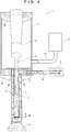
FIG. 4] FIG. 4 is a schematic longitudinal section illustrating the electron beam irradiation device according to an example of the present invention. - [
FIG. 5] FIG. 5 is an enlarged view illustrating a tip part of a vacuum nozzle as a principal part of the electron beam irradiation device. - Referring to
FIGS. 1 and2 , an electron beam irradiation device according to an embodiment of the present invention will be described below. - As illustrated in
FIG. 1 , an electronbeam irradiation device 1 includes avacuum chamber 2 in which anelectron beam generator 21 is disposed, avacuum nozzle 3 that is connected to thevacuum chamber 2 with airtightness so as to guide an electron beam E from theelectron beam generator 21, and awindow foil 4 that is disposed on the tip of thevacuum nozzle 3 and allows the transmission of the electron beam E from the inside of thevacuum nozzle 3 to the outside. - The
vacuum chamber 2 is evacuated in order to accelerate the electron beam E from theelectron beam generator 21. Power for generating the electron beam E is supplied to theelectron beam generator 21 from, for example, a power supply disposed outside thevacuum chamber 2. The power supply is not illustrated. Thevacuum nozzle 3 is evacuated along with thevacuum chamber 2. Thewindow foil 4 seals the tip of thevacuum nozzle 3 and radiates the transmitted electron beam E to the outside of thevacuum nozzle 3. The transmission of the electron beam E heats thewindow foil 4. For cooling thewindow foil 4, the electronbeam irradiation device 1 is configured as follows: - As illustrated in
FIG. 2 , the electronbeam irradiation device 1 further includes anouter pipe 7 surrounding the outer surface of thevacuum nozzle 3, a cooling-gas supply unit 9 that supplies cooling gas C (e.g., air) into acoolant passage 8, that is, aclearance 8 between thevacuum nozzle 3 and theouter pipe 7, and a heat-conductingtransmission foil 6 that is fit with a low density and a high thermal conductivity to thewindow foil 4 and is in contact with the tip of thevacuum nozzle 3. Additionally, at least a tip part of thevacuum nozzle 3 is made of a thermal conductive material (a material having at least a thermal conductivity of copper). In other words, in the electronbeam irradiation device 1, heat from thewindow foil 4 is quickly transmitted to the tip part of thevacuum nozzle 3 by the heat-conductingtransmission foil 6 and the transmitted heat is quickly transferred to the cooling gas C supplied into theclearance 8 between thevacuum nozzle 3 and theouter pipe 7. This configuration sufficiently cools thewindow foil 4 and thus eliminates the need for makeing the cooling gas C impinge on thewindow foil 4 directly through theouter pipe 7. Thus, theouter pipe 7 has a fixed internal diameter (including manufacturing errors such as a tolerance). The tip part of thevacuum nozzle 3 is made of the thermal conductive material (a material having at least a thermal conductivity of copper) and may have any length as long as heat from thewindow foil 4 is quickly transferred to the cooling gas C. For example, the tip part is at least four times longer than the internal diameter of thevacuum nozzle 3. If the tip part is at least four times longer than the internal diameter of thevacuum nozzle 3, an area exposed to the cooling gas C on the tip part is at least 16 times larger than the area of the window foil 4 (to be accurate, the area of one side inside the vacuum nozzle 3), that is, the tip part is so wide that heat transmitted from thewindow foil 4 to the tip part is quickly transferred to the cooling gas C. - The heat-conducting
transmission foil 6 having a low density and a high thermal conductivity is foil made of a material having a value of at least 63 × 10-3, which is determined by dividing a thermal conductivity [W/(m·K)] by a density [kg/m3]. The material satisfies Expression (1) below.
- In addition to quick heat transfer with a high thermal conductivity from the
window foil 4 to the tip part of thevacuum nozzle 3, the heat-conductingtransmission foil 6 hardly generates heat even when the electron beam E is transmitted due to the low density. Examples of specific materials of the heat-conductingtransmission foil 6, that is, examples of materials satisfying Expression (1) include beryllium, carbon materials (e.g., graphite, graphene, or a carbon nanotube), aluminum or silicon, or compounds thereof. Hereinafter, thewindow foil 4 and the heat-conductingtransmission foil 6 fit onto thewindow foil 4 will be collectively referred to as alaminated foil 46. - The tip of the
vacuum nozzle 3 and the heat-conductingtransmission foil 6 may be hardly bonded to each other depending on the materials of thevacuum nozzle 3 and the heat-conductingtransmission foil 6. In this case, as illustrated inFIG. 3 , an exploded perspective view of a longitudinal section, anadhesive member 36 that is highly adhesive to both of the tip of thevacuum nozzle 3 and the heat-conductingtransmission foil 6 may be interposed therebetween. In order not to hinder the passage of the electron beam E, theadhesive member 36 is ring-shaped. Also in the case where theadhesive member 36 is interposed, the heat-conductingtransmission foil 6 and the tip of thevacuum nozzle 3 are preferably brought into contact with each other in order to quickly transmit heat from the heat-conductingtransmission foil 6 to the tip part of thevacuum nozzle 3. In addition to the configuration ofFIG. 3 , theadhesive member 36 highly adhesive to both of the tip of thevacuum nozzle 3 and thewindow foil 4 may be interposed so as to indirectly bond the tip of thevacuum nozzle 3 and thewindow foil 4. - In view of quick transfer of heat from the heat-conducting
transmission foil 6 to the tip part of thevacuum nozzle 3, it is preferably smooth the contact surfaces of the heat-conductingtransmission foil 6 and the tip of the vacuum nozzle 3 (e.g., arithmetic mean roughness Ra ≤ 0.4). Naturally, the smoothed contact surfaces achieve connection with firmer air tightness as well as quick transfer of heat. - A method for manufacturing the electron
beam irradiation device 1 will be described below. - The method for manufacturing the electron
beam irradiation device 1 includes a laminated foil forming step in which the heat-conductingtransmission foil 6 is fitted to thewindow foil 4 so as to form thelaminated foil 46, a laminated foil placing step in which thelaminated foil 46 is placed on the tip of thevacuum nozzle 3, and a connecting step in which thevacuum nozzle 3 is connected to thevacuum chamber 2. In these steps, the laminated foil placing step follows the laminated foil forming step. The order of the connecting step is not limited. - In the laminated foil forming step, the
window foil 4 and the heat-conductingtransmission foil 6 are fitted to each other by pressure welding. In this case, pressure welding is a bonding method for applying heat and/or a pressure to the adjoining contact surfaces of thewindow foil 4 and the heat-conductingtransmission foil 6 so as to metallically fuse the atoms of thewindow foil 4 and the heat-conductingtransmission foil 6. The bonding method is, for example, diffusion bonding. Thelaminated foil 46 is formed by pressure welding, so that thewindow foil 4 and the heat-conductingtransmission foil 6 are firmly fitted to each other. Thus, thelaminated foil 46 is unlikely to be broken even under severe conditions such as a high pressure applied by sealing the evacuatedvacuum nozzle 3 and heat generated by the transmitted electron beam E. - In the laminated foil placing step, in order to place the formed
laminated foil 46 on the tip of thevacuum nozzle 3, thelaminated foil 46 is bonded to the tip of thevacuum nozzle 3 by, for example, brazing. - In the connecting step, the
vacuum chamber 2 and thevacuum nozzle 3 are directly connected to each other or indirectly connected to each other via a flange or the like (not illustrated). Thevacuum chamber 2 in the connecting step may contain necessary devices such as theelectron beam generator 21 and a power supply or the necessary devices may be disposed in thevacuum chamber 2 after the connecting step. - The operations of the electron
beam irradiation device 1 will be described below. - First, power is supplied to the
electron beam generator 21 from the power supply (not illustrated), so that the electron beam E is generated from theelectron beam generator 21 as illustrated inFIGS. 1 and2 . The electron beam E is accelerated in thevacuum chamber 2 and thevacuum nozzle 3, is guided into thevacuum nozzle 3, and then passes through thelaminated foil 46. This mainly heats thewindow foil 4. Heat from thewindow foil 4 is immediately transmitted to the tip part of thevacuum nozzle 3 through the heat-conductingtransmission foil 6. The transmitted heat is quickly transferred to the cooling gas C supplied to theclearance 8 between thevacuum nozzle 3 and theouter pipe 7. Thus, thewindow foil 4 is sufficiently cooled. - In this way, the
window foil 4 is sufficiently cooled in the electronbeam irradiation device 1, thereby eliminating the need for a complicated configuration for cooling thewindow foil 4. This can achieve a simple configuration. - Moreover, the heat-conducting
transmission foil 6 is made of the material that is easily obtained, such as beryllium, carbon materials, aluminum or silicon, or compounds thereof, achieving a simpler configuration. - Furthermore, the
adhesive member 36 placed as illustrated inFIG. 3 firmly bonds the heat-conductingtransmission foil 6 to the tip of thevacuum nozzle 3, thereby improving the durability. - Additionally, according to the method for manufacturing the electron
beam irradiation device 1, thewindow foil 4 and the heat-conductingtransmission foil 6 are firmly bonded to each other by contact bonding, thereby further improving durability. - In the present embodiment, at least the tip part of the
vacuum nozzle 3 is made of the thermal conductive material (a material having at least a thermal conductivity of copper). The thermal conductive material is used to transfer heat from thewindow foil 4 to the cooling gas C at least on the tip part of thevacuum nozzle 3. Thus, the part of the thermal conductive material (a material having at least a thermal conductivity of copper) in thevacuum nozzle 3 is preferably exposed as large an area as possible to the cooling gas C. In other words, the part of the thermal conductive material (a material having at least a thermal conductivity of copper) in thevacuum nozzle 3 preferably extends so as to be entirely surrounded by theouter pipe 7. As illustrated inFIGS. 1 and2 , theoverall vacuum nozzle 3 is made of the conductive material (a material having at least a thermal conductivity of copper). This configuration is further preferable because heat is transferred from a part not surrounded by theouter pipe 7 in addition to the cooling gas C. - In the embodiment, the heat-conducting
transmission foil 6 in thelaminated foil 46 is illustrated near thevacuum nozzle 3. Thewindow foil 4 may be disposed near thevacuum nozzle 3. In thelaminated foil 46, the foil having lower corrosion resistance is disposed near thevacuum nozzle 3 and thus thelaminated foil 46 becomes less corrosive, further improving the durability. - In the embodiment, the cooling-
gas supply unit 9 supplies the cooling gas C. The cooling-gas supply unit 9 may supply and collect the cooling gas C (in other words, the cooling gas C is circulated). The cooling-gas supply unit 9 may be replaced with a cooling-liquid supply unit that supplies and circulates a cooling liquid (water or oil). This configuration is further preferable because the cooling liquid efficiently collects heat from the tip part. - Additionally, in the embodiment, the tip part of the
vacuum nozzle 3 has a flat outer surface. The outer surface of the tip part may have a large number of grooves so as to increase the area of the tip part exposed to the cooling gas C. In particular, the grooves are more preferably formed perpendicularly to the axis of the vacuum nozzle 3 (that is, a large number of circumferential grooves) because the cooling gas C efficiently collects heat from the tip part. As a matter of course, the grooves may be replaced with a large number of projections. In order to more efficiently transfer heat from the tip part to the cooling gas C, a cooling fin may be provided on the tip part. - In the embodiment, the shape and thickness of the heat-conducting
transmission foil 6 were not specifically described. The heat-conductingtransmission foil 6 may have any shape and thickness as long as heat is quickly transferred from thewindow foil 4 to the tip part of thevacuum nozzle 3 and heat is hardly generated even when the electron beam E is transmitted due to the low density. For example, the heat-conductingtransmission foil 6 is preferably so thick that heat other than heat transferred through thewindow foil 4 exposed to the atmosphere (other than convective heat transfer and thermal radiation) is completely transmitted to the tip part of thevacuum nozzle 3. Specifically, if thewindow foil 4 is a titanium foil having a thickness of 5 µm and the heat-conductingtransmission foil 6 is an aluminum foil having a thickness of 8 µm, at least about 99% of heat generated on the titanium foil by the transmission of the electron beam E is transmitted to the tip part of thevacuum nozzle 3 so as to cool the titanium foil. This leaves only a small amount of heat on the titanium foil and thus the heat is sufficiently transferred through the titanium foil exposed to the atmosphere. Hence, a temperature increase on the titanium foil is suppressed. For comparison, in the related art where the heat-conductingtransmission foil 6 is not provided (in other words, only thewindow foil 4 is provided) and thewindow foil 4 is a titanium foil having a thickness of 10 µm, about 75% of heat generated on the titanium foil by the transmission of the electron beam E is transmitted to the tip part of thevacuum nozzle 3 so as to cool the titanium foil. This leaves a larger amount of heat on the titanium foil and thus the heat is not sufficiently transferred through the titanium foil exposed to the atmosphere. Hence, a temperature increase on the titanium foil is not suppressed. - A simulation was conducted to confirm the effect of the embodiment. First, conditions were set as follows: the titanium foil and the aluminum foil had the thicknesses described in the embodiment, the
vacuum nozzle 3 had an internal diameter of 4 mm, and the electron beam E was generated so as to heat the tip and base of thevacuum nozzle 3 to temperatures of 700 K and 400 K, respectively. As a result, in the case of a foil including a titanium foil (5 µm thick) and an aluminum foil (8 µm thick) on the tip of thevacuum nozzle 3, the titanium foil was cooled by no less than 7.6 W without forced air-cooling. In contrast, in the case of a foil only including a titanium foil (10 µm thick) on the tip of thevacuum nozzle 3, the titanium foil was cooled only by 1.2 W with forced air-cooling. Thus, it is assumed that the foil including thewindow foil 4 and the heat-conductingtransmission foil 6, that is, thelaminated foil 46 on the tip of thevacuum nozzle 3 is more resistant to the electron beam E having a large current. - According to a more specific example of the embodiment, the electron
beam irradiation device 1 will be described below based on the accompanying drawings. Configurations omitted in the embodiment will be mainly discussed. The same configurations as those of the embodiment are indicated by the same reference numerals and the explanation thereof is omitted. - As illustrated in
FIG. 4 , the electronbeam irradiation device 1 according to the example includes avacuum pump 12 for evacuating thevacuum chamber 2 and thevacuum nozzle 3, and a vacuum L-shapedpipe 13 connecting thevacuum chamber 2 and thevacuum pump 12. Moreover, the electronbeam irradiation device 1 includes anexternal flange 18 that fixes thevacuum nozzle 3 to thevacuum chamber 2 and guides the cooling gas C into thecoolant passage 8, and acoolant pipe 19 connecting theexternal flange 18 and the cooling-gas supply unit 9. - The
vacuum chamber 2 includes aninternal flange 22 for fixing theelectron beam generator 21. Theinternal flange 22 is disposed on the opposite end of thevacuum chamber 2 from thevacuum nozzle 3. Thevacuum nozzle 3 is made of a copper alloy. Thevacuum pump 12 is capable of setting the interiors of thevacuum chamber 2 and thevacuum nozzle 3 at a degree of vacuum (high vacuum to ultrahigh vacuum) suitable for accelerating the electron beam E. The vacuum L-shapedpipe 13 is positioned so as to separate thevacuum pump 12 from the electron beam E in thevacuum chamber 2 while locating the axis of thevacuum pump 12 in parallel with the axis of thevacuum chamber 2. Thus, even if a magnetic field is generated by thevacuum pump 12, the influence of the magnetic field on the electron beam E can be reduced. - The
external flange 18 stably holds thevacuum nozzle 3 cantilevered from thevacuum chamber 2 and simplifies a structure from thecoolant pipe 19 to thecoolant passage 8, that is, a structure that guides the cooling gas C from thecoolant pipe 19 to thecoolant passage 8. Thecoolant pipe 19 is not particularly limited but is preferably short in length such that the cooling gas C does not collect heat other than heat from thevacuum nozzle 3, which is unnecessary heat. - As illustrated in
FIG. 5 , thewindow foil 4 is not limited as long as thewindow foil 4 allows the transmission of the electron beam E and is resistant to a high atmospheric pressure applied by sealing the evacuatedvacuum nozzle 3. Thewindow foil 4 is, for example, a titanium foil having a uniform thickness of about 1 µm to 10 µm (preferably about 3 µm to 5 µm). The heat-conductingtransmission foil 6 is, for example, an aluminum foil similarly having a uniform thickness of about 2 µm to 20 µm (preferably about 5 µm to 15 µm). Thelaminated foil 46 including thewindow foil 4 and the heat-conducting transmission foil 6 (strictly speaking, also including a boundary layer 5) is quite thin and always receives a high atmospheric pressure and thus is easily broken by an unexpected collision or the like. Thus, the structure is formed such that thelaminated foil 46 disposed on the tip of thevacuum nozzle 3 is sufficiently surrounded by theouter pipe 7, that is, the tip of theouter pipe 7 projects out of the tip of thevacuum nozzle 3. The projection has any length as long as thelaminated foil 46 is protected by theouter pipe 7. The projection is not shorter than, for example, the internal diameter of thevacuum nozzle 3. - A method for manufacturing the electron
beam irradiation device 1 will be described below. - As the laminated foil forming step, the
window foil 4 and the heat-conductingtransmission foil 6 are fitted to each other by diffusion bonding. As illustrated inFIG. 5 , through the diffusion bonding, theboundary layer 5 is formed between thewindow foil 4 and the heat-conductingtransmission foil 6 by chemical bonding between the material of thewindow foil 4 and the material of the heat-conductingtransmission foil 6. Theboundary layer 5 has any thickness as long as thewindow foil 4 and the heat-conductingtransmission foil 6 are fitted to each other. Thus, the time for diffusion bonding is set such that theboundary layer 5 is sufficiently thick. - The operations of the electron
beam irradiation device 1 will be described below. - First, as illustrated in
FIG. 4 , thevacuum pump 12 evacuates thevacuum chamber 2 and thevacuum nozzle 3 to a degree of vacuum (high vacuum to ultrahigh vacuum) suitable for accelerating the electron beam E. Subsequently, power is supplied to theelectron beam generator 21 from the power supply (not illustrated), so that the electron beam E is generated from theelectron beam generator 21. The electron beam E is accelerated in thevacuum chamber 2 and thevacuum nozzle 3, is guided into thevacuum nozzle 3, and then passes through thelaminated foil 46. This mainly heats thewindow foil 4. Heat from thewindow foil 4 is immediately transmitted to the tip part of thevacuum nozzle 3 through the heat-conductingtransmission foil 6. Since thevacuum nozzle 3 is entirely made of a copper alloy, heat from the heat-conductingtransmission foil 6 is transmitted over thevacuum nozzle 3. Most of the heat transmitted to thevacuum nozzle 3 is quickly transferred to the cooling gas C supplied into theclearance 8 between thevacuum nozzle 3 and theouter pipe 7. Thus, thewindow foil 4 is sufficiently cooled. - In addition to the effect of the electron
beam irradiation device 1 according to the embodiment, the electronbeam irradiation device 1 of the present example achieves the following effect: The durability is further improved for the following reasons. Firstly, as illustrated inFIG. 5 , thelaminated foil 46 of the present example includes theboundary layer 5 firmly bonding thewindow foil 4 and the heat-conductingtransmission foil 6 and is surrounded by theouter pipe 7. Secondly, as illustrated inFIG. 4 , thevacuum nozzle 3 is fixed to theexternal flange 18 so as to be connected to thevacuum chamber 2. - In the example, the detail of the
vacuum nozzle 3 was specifically determined and a simulation result was obtained as follows: Thevacuum nozzle 3 was 150 mm in length, 4 mm in internal diameter, and 1 mm in thickness and was made of copper. The electron beam E was generated so as to heat the tip and base of thevacuum nozzle 3 to temperatures of 400 K and 300 K, respectively. In this case, a heat quantity of no less than 7.48 W was transferred and sufficient cooling was achieved. For comparison, under the same conditions except that thevacuum nozzle 3 was replaced with a stainless vacuum nozzle, only a heat quantity of 1.64 W was transferred and resulted in insufficient cooling. - The embodiment and the example are merely exemplary and are not restrictive in all the aspects. The scope of the present invention is not indicated by the foregoing description but the claims. The scope of the present invention is intended to include meanings equivalent to the claims and all changes in the scope. From among the configurations described in the embodiment and the example, the configurations other than that described as a first invention in "Solution to Problem" are optional and thus can be deleted and changed as appropriate.
Claims (5)
- An electron beam irradiation device comprising:a vacuum chamber;an electron beam generator disposed in the vacuum chamber;a vacuum nozzle connected to the vacuum chamber with air tightness so as to guide an electron beam from the electron beam generator;a window foil that is disposed on a tip of the vacuum nozzle and allows the transmission of the electron beam from inside to outside of the vacuum nozzle;an outer pipe surrounding an outer surface of the vacuum nozzle;a cooling-gas supply unit that supplies cooling gas into a coolant passage formed as a clearance between the vacuum nozzle and the outer pipe; anda heat-conducting transmission foil that is fitted to the window foil and is in contact with the tip of the vacuum nozzle,wherein the heat-conducting transmission foil is made of a material having a value of at least 63 × 10-3, which is determined by dividing a thermal conductivity [W/(m·K)] by a density [kg/m3], andat least a tip part of the vacuum nozzle is made of a material having at least a thermal conductivity of copper.
- The electron beam irradiation device according to claim 1, wherein the heat-conducting transmission foil is made of beryllium, a carbon material, aluminum or silicon, or compounds thereof.
- The electron beam irradiation device according to one of claims 1 and 2, wherein one of the window foil and the heat-conducting transmission foil with lower corrosion resistance is disposed near the vacuum nozzle.
- The electron beam irradiation device according to one of claims 1 and 2, further comprising an adhesive member between the tip of the vacuum nozzle and one of the heat-conducting transmission foil and the window foil.
- A method for manufacturing the electron beam irradiation device according to one of claims 1 and 2, comprising:forming the laminated foil by fitting the heat-conducting transmission foil to the window foil;placing the laminated foil on the tip of the vacuum nozzle; andconnecting the vacuum nozzle to the vacuum chamber,wherein in the formation of the laminated foil, the window foil and the heat-conducting transmission foil are fitted to each other by pressure welding.
Applications Claiming Priority (2)
| Application Number | Priority Date | Filing Date | Title |
|---|---|---|---|
| JP2017174435A JP6843023B2 (en) | 2017-09-12 | 2017-09-12 | Electron beam irradiation device and its manufacturing method |
| PCT/JP2018/032843 WO2019054245A1 (en) | 2017-09-12 | 2018-09-05 | Electron beam irradiation device and method for manufacturing same |
Publications (2)
| Publication Number | Publication Date |
|---|---|
| EP3683803A1 true EP3683803A1 (en) | 2020-07-22 |
| EP3683803A4 EP3683803A4 (en) | 2021-05-05 |
Family
ID=65722835
Family Applications (1)
| Application Number | Title | Priority Date | Filing Date |
|---|---|---|---|
| EP18856749.9A Withdrawn EP3683803A4 (en) | 2017-09-12 | 2018-09-05 | ELECTRON BEAM IRRADIATION DEVICE AND ITS MANUFACTURING PROCESS |
Country Status (4)
| Country | Link |
|---|---|
| US (1) | US20200273594A1 (en) |
| EP (1) | EP3683803A4 (en) |
| JP (1) | JP6843023B2 (en) |
| WO (1) | WO2019054245A1 (en) |
Families Citing this family (1)
| Publication number | Priority date | Publication date | Assignee | Title |
|---|---|---|---|---|
| CN117886057B (en) * | 2024-03-15 | 2024-06-04 | 天津蓝孚高能物理技术有限公司 | Conveying device for irradiation sterilization of electron accelerator |
Family Cites Families (8)
| Publication number | Priority date | Publication date | Assignee | Title |
|---|---|---|---|---|
| JPS5526845A (en) | 1978-08-15 | 1980-02-26 | Matsushita Electric Works Ltd | Domestic smoking device |
| DE3108006A1 (en) * | 1981-03-03 | 1982-09-16 | Siemens AG, 1000 Berlin und 8000 München | RADIATION EXIT WINDOW |
| WO2007095205A2 (en) * | 2006-02-14 | 2007-08-23 | Advanced Electron Beams, Inc. | Electron beam emitter |
| EP1982920A1 (en) * | 2007-04-19 | 2008-10-22 | Krones AG | Device for sterilising containers |
| CN103229269B (en) * | 2010-12-02 | 2016-09-07 | 利乐拉瓦尔集团及财务有限公司 | Electron exit window foil |
| JP6373262B2 (en) * | 2013-04-26 | 2018-08-15 | 日立造船株式会社 | Electron beam irradiation device |
| WO2015125414A1 (en) * | 2014-02-19 | 2015-08-27 | Hitachi Zosen Corporation | Electron beam irradiator with enhanced cooling efficiency of the transmission window |
| JP6068693B1 (en) * | 2016-01-08 | 2017-01-25 | 浜松ホトニクス株式会社 | Electron beam irradiation device |
-
2017
- 2017-09-12 JP JP2017174435A patent/JP6843023B2/en active Active
-
2018
- 2018-09-05 EP EP18856749.9A patent/EP3683803A4/en not_active Withdrawn
- 2018-09-05 WO PCT/JP2018/032843 patent/WO2019054245A1/en not_active Ceased
- 2018-09-05 US US16/646,382 patent/US20200273594A1/en not_active Abandoned
Also Published As
| Publication number | Publication date |
|---|---|
| US20200273594A1 (en) | 2020-08-27 |
| JP6843023B2 (en) | 2021-03-17 |
| JP2019049499A (en) | 2019-03-28 |
| EP3683803A4 (en) | 2021-05-05 |
| WO2019054245A1 (en) | 2019-03-21 |
Similar Documents
| Publication | Publication Date | Title |
|---|---|---|
| JP6039282B2 (en) | Radiation generator and radiation imaging apparatus | |
| US6307916B1 (en) | Heat pipe assisted cooling of rotating anode x-ray tubes | |
| US6263046B1 (en) | Heat pipe assisted cooling of x-ray windows in x-ray tubes | |
| EP2816584A1 (en) | Device for generating x-rays having a liquid metal anode | |
| US9281158B2 (en) | X-ray emitting target and X-ray emitting device | |
| EP2740331B1 (en) | Radiation generating apparatus and radiation imaging apparatus | |
| US5052034A (en) | X-ray generator | |
| US9425021B2 (en) | X-ray generation apparatus and X-ray radiographic apparatus | |
| US20170133192A1 (en) | X-ray generator and x-ray imaging apparatus | |
| JP2013157269A (en) | Target structure and radiation generator equipped with the same | |
| JP6640401B1 (en) | heatsink | |
| US9648710B2 (en) | High power X-ray tube housing | |
| US20140126701A1 (en) | X-ray emitting target and x-ray emitting device | |
| US6304631B1 (en) | X-ray tube vapor chamber target | |
| US20200273594A1 (en) | Electron beam irradiation device and method for manufacturing same | |
| US7042981B2 (en) | X-ray tube window and surrounding enclosure cooling apparatuses | |
| US8565381B2 (en) | Radiation source and method for the generation of X-radiation | |
| CN107195516A (en) | X-ray target and the X-ray generator for possessing the x-ray target | |
| US8130910B2 (en) | Liquid-cooled aperture body in an x-ray tube | |
| US20110038461A1 (en) | Evacuated enclosure window cooling | |
| US9589760B2 (en) | X-ray generator | |
| JP2016211850A (en) | Electron beam irradiation device | |
| KR102195101B1 (en) | X-ray tube | |
| JP2014149932A (en) | Radiation generator and radiographic system | |
| JP5797037B2 (en) | Electron beam irradiation device |
Legal Events
| Date | Code | Title | Description |
|---|---|---|---|
| PUAI | Public reference made under article 153(3) epc to a published international application that has entered the european phase |
Free format text: ORIGINAL CODE: 0009012 |
|
| STAA | Information on the status of an ep patent application or granted ep patent |
Free format text: STATUS: REQUEST FOR EXAMINATION WAS MADE |
|
| 17P | Request for examination filed |
Effective date: 20200307 |
|
| AK | Designated contracting states |
Kind code of ref document: A1 Designated state(s): AL AT BE BG CH CY CZ DE DK EE ES FI FR GB GR HR HU IE IS IT LI LT LU LV MC MK MT NL NO PL PT RO RS SE SI SK SM TR |
|
| AX | Request for extension of the european patent |
Extension state: BA ME |
|
| DAV | Request for validation of the european patent (deleted) | ||
| DAX | Request for extension of the european patent (deleted) | ||
| 18W | Application withdrawn |
Effective date: 20210401 |
|
| A4 | Supplementary search report drawn up and despatched |
Effective date: 20210408 |
|
| RIC1 | Information provided on ipc code assigned before grant |
Ipc: G21K 5/00 20060101AFI20210331BHEP Ipc: G21K 5/04 20060101ALI20210331BHEP Ipc: A61L 2/08 20060101ALI20210331BHEP Ipc: B01J 19/12 20060101ALI20210331BHEP Ipc: H01J 33/04 20060101ALI20210331BHEP Ipc: H01J 5/18 20060101ALI20210331BHEP Ipc: B65B 55/08 20060101ALN20210331BHEP |