EP3683642A1 - Method for measuring fatigue for mechanical components of an aircraft - Google Patents
Method for measuring fatigue for mechanical components of an aircraft Download PDFInfo
- Publication number
- EP3683642A1 EP3683642A1 EP20152073.1A EP20152073A EP3683642A1 EP 3683642 A1 EP3683642 A1 EP 3683642A1 EP 20152073 A EP20152073 A EP 20152073A EP 3683642 A1 EP3683642 A1 EP 3683642A1
- Authority
- EP
- European Patent Office
- Prior art keywords
- data
- mechanical components
- ignitions
- glss
- operating life
- Prior art date
- Legal status (The legal status is an assumption and is not a legal conclusion. Google has not performed a legal analysis and makes no representation as to the accuracy of the status listed.)
- Granted
Links
Images



Classifications
-
- G—PHYSICS
- G05—CONTROLLING; REGULATING
- G05B—CONTROL OR REGULATING SYSTEMS IN GENERAL; FUNCTIONAL ELEMENTS OF SUCH SYSTEMS; MONITORING OR TESTING ARRANGEMENTS FOR SUCH SYSTEMS OR ELEMENTS
- G05B23/00—Testing or monitoring of control systems or parts thereof
- G05B23/02—Electric testing or monitoring
- G05B23/0205—Electric testing or monitoring by means of a monitoring system capable of detecting and responding to faults
- G05B23/0259—Electric testing or monitoring by means of a monitoring system capable of detecting and responding to faults characterized by the response to fault detection
- G05B23/0283—Predictive maintenance, e.g. involving the monitoring of a system and, based on the monitoring results, taking decisions on the maintenance schedule of the monitored system; Estimating remaining useful life [RUL]
-
- G—PHYSICS
- G07—CHECKING-DEVICES
- G07C—TIME OR ATTENDANCE REGISTERS; REGISTERING OR INDICATING THE WORKING OF MACHINES; GENERATING RANDOM NUMBERS; VOTING OR LOTTERY APPARATUS; ARRANGEMENTS, SYSTEMS OR APPARATUS FOR CHECKING NOT PROVIDED FOR ELSEWHERE
- G07C5/00—Registering or indicating the working of vehicles
- G07C5/008—Registering or indicating the working of vehicles communicating information to a remotely located station
-
- G—PHYSICS
- G05—CONTROLLING; REGULATING
- G05B—CONTROL OR REGULATING SYSTEMS IN GENERAL; FUNCTIONAL ELEMENTS OF SUCH SYSTEMS; MONITORING OR TESTING ARRANGEMENTS FOR SUCH SYSTEMS OR ELEMENTS
- G05B2219/00—Program-control systems
- G05B2219/20—Pc systems
- G05B2219/26—Pc applications
- G05B2219/2637—Vehicle, car, auto, wheelchair
Definitions
- the present invention relates to a method for verifying the integrity of operating life data of mechanical components of a system subject to fatigue.
- an aircraft comprises a set of mechanical components, in particular of the rotary type, like, for example gearboxes (GB), turbines and compressors.
- GB gearboxes
- turbines turbines
- compressors compressors
- each flight session comprises one or more flight operations, like for example, take-off, landing, cruising, test flight and/or emergency flight.
- flight operations like for example, take-off, landing, cruising, test flight and/or emergency flight.
- the aircraft carries out a single flight session, the latter comprising different flight operations.
- one or more rotary mechanical components are activated for respective one or more operating periods, i.e. time periods (measured, for example, in hours) that lapse between the ignition and the shutting down of the respective rotary mechanical component; in particular, each operating period is defined as fatigue cycle.
- each fatigue cycle depends on different factors, like, for example, the type of flight operation carried out, the environmental conditions (for example air pressure and temperature) and the interactions between the rotary mechanical components of the flight configuration during the performance of the one or more flight operations.
- Each rotary mechanical component can be activated many times in a single flight operation; therefore, each rotary mechanical component can carry out many fatigue cycles in a single flight operation of the flight session of the aircraft.
- each rotary mechanical component has accumulated many hours of operation and, therefore, many fatigue cycles; in particular, the total number of hours of operation accumulated by each rotary mechanical component at the end of the flight session contributes to defining an operating life for each rotary mechanical component.
- the operating life of a rotary mechanical component is the number of hours of operation elapsed during the aforementioned flight session (and, therefore, the one or more flight operations) relative to the aforementioned rotary mechanical component; in greater detail, the operating life of a rotary mechanical component is an indicator of the number of fatigue cycles carried out in the aforementioned flight session of the aircraft.
- Each rotary mechanical component is capable of operating for a maximum number of hours of operation, i.e. a maximum number of fatigue cycles, beyond which the aforementioned rotary mechanical component must be replaced for safety reasons. Therefore, the rotary mechanical component has a maximum operating life.
- FIG 1 schematically shows a flight apparatus 1 comprising a ground logistic-support system (GLSS) 3 and an aircraft 5.
- GLSS ground logistic-support system
- the aircraft 5 comprises: a flight configuration 9, which, for the sake of simplicity, comprises only m rotary mechanical components Ci (for example, five shown in figure 1 and indicated hereinafter with reference symbols C 1 -C 5 ), in which i is an integer comprised between 1 and m.
- a flight configuration 9 which, for the sake of simplicity, comprises only m rotary mechanical components Ci (for example, five shown in figure 1 and indicated hereinafter with reference symbols C 1 -C 5 ), in which i is an integer comprised between 1 and m.
- the aircraft 5 also comprises an on-board computer (OBC) 8, coupled to the flight configuration 9; in particular, the OBC 8 is adapted for controlling the flight configuration 9 (in particular, the rotary mechanical components C 1 -C 5 ) during one or more flight operations carried out in one or more flight sessions of the aircraft 5. Moreover, the OBC 8 is adapted for determining and storing flight data relative to the rotary mechanical components C 1 -C 5 after having carried out one or more flight sessions; in detail, the flight data comprise, for example: the hours of operation relative to each rotary mechanical component C 1 -C 5 ; and a number of ignitions N of the aircraft 5.
- OBC on-board computer
- the number of ignitions N represents the number of times in which the aircraft 5 is controlled to carry out any flight operation; in other words, the number of ignitions N is an indicator of the total number of flight operations carried out by the aircraft 5.
- the aircraft 5 can operate in normal mode for a number of ignitions N a ; in test mode for a number of ignitions N t ; and in emergency mode for a number of ignitions N e . Consequently, the aircraft 5 carries out N a flight operations in normal mode, N t flight operations in test mode and N e flight operations in emergency mode.
- the number of ignitions N is defined as the sum of the number of ignitions N a , N t and N e ; in addition, the number of ignitions N, as well as the ignition numbers N a , N t and N e increases after each flight operation carried out by the aircraft 5.
- the GLSS 3 comprises many data storage modules, adapted for receiving and storing data relative to the rotary mechanical components C 1 -C 5 of the aircraft 5; in particular, the GLSS 3 of figure 1 includes: an aircraft configuration module 10, comprising identifying data (for example, part number, serial number, hours of operation and maximum number of fatigue cycles) relative to the rotary mechanical components C 1 -C 5 ; a data downloading module 12 adapted for receiving and decoding the flight data relative to the flight configuration 9 after every flight session carried out by the aircraft 5; and a maintenance module 14, adapted for storing maintenance data (for example, serial number and hours of operation) of replaced rotary mechanical components that, when mounted instead of the corresponding rotary mechanical components C 1 -C 5 in maintenance step, modify the flight configuration 9.
- an aircraft configuration module 10 comprising identifying data (for example, part number, serial number, hours of operation and maximum number of fatigue cycles) relative to the rotary mechanical components C 1 -C 5
- a data downloading module 12 adapted for receiving and decoding the flight data relative to the flight configuration
- a Portable Maintenance Data Storage (PMDS) 20 can be coupled to the data downloading module 12 of the GLSS 3 and to the OBC 8 of the aircraft 5; for example, the PMDS 20 is a cassette storage device. Moreover, the PMDS 20 is adapted for storing the identifying data of the rotary mechanical components C 1 -C 5 and the relative flight data after the one or more flight sessions, as well as transmitting such flight data to the GLSS 3 (in particular, to the data downloading module 12).
- the PMDS 20 is initialized according to the method illustrated in figure 2 and described hereinafter.
- the PMDS 20 is connected to a processor (not shown), through which a user (for example, a maintenance worker) inserts the identifying data relative to the rotary mechanical components C 1 -C 5 of the flight configuration 9 (block 30).
- a user for example, a maintenance worker
- the identifying data relative to each rotary mechanical component Ci comprise fixed data and variable data.
- the fixed data comprise, for example: a part number P/N j (in which j is an integer comprised between 1 and k, where k is an integer, less than m), indicating a category (or series) to which the aforementioned rotary mechanical component Ci belongs; a serial number S/N i , indicating a number identifying the aforementioned rotary mechanical component Ci; and maximum number of fatigue cycles N Cmax, i .
- the variable data comprise an initial operating life datum Tv 0, i (if present, like, for example, in the case of reconditioned rotary mechanical components), indicating the hours of operation elapsed of the relative rotary mechanical component Ci.
- the maintenance worker associates one or more serial numbers S/N i to each part number P/N j ; in particular, rotary mechanical components Ci of the same category have the same part number P/N j but a different serial number S/N i . Therefore, a part number P/N j and one or more serial numbers S/N i relative to one or more rotary mechanical components Ci of the same category directly correspond to one another.
- the maintenance worker uniquely associates each serial number S/N i with data relative to the operation of each rotary mechanical component Ci, in particular initial operating life data Tv 0, i and maximum number of fatigue cycles N Cmax, i .
- each rotary mechanical component Ci is identified with a relative part number P/N j , a relative serial number S/N i , relative initial operating life data Tv 0 , i and relative number of fatigue cycles N Cmax,i .
- each rotary mechanical component C 1 -C 5 is characterised by respective part numbers P/N 1 -P/N 3 , respective serial numbers S/N 1 -S/N 5 , respective initial operating life data Tv 0, 1 - Tv 0, 5 and respective maximum numbers of fatigue cycles N Cmax, 1 -N Cmax, 5 .
- the flight configuration module 10 stores such identifying data for example in table format, as shown schematically in figure 4A .
- the PMDS 20 has stored the identifying data (in particular, the hours of operation) relative to the flight configuration 9 of the aircraft 5.
- the PDMS 20 is disconnected from the GLSS 3 and connected to the OBC 8 of the aircraft 5.
- the PDMS 20 transmits the identifying data of the flight configuration 9 to the OBC 8, which receives them and stores them in an internal memory (not shown).
- Such identifying data stored in the OBC 8 constitute the starting data for the subsequent operations of the initialisation method, described hereinafter.
- the maintenance worker carries out one or more ground tests of the aircraft 5.
- the one or more ground tests are followed for some rotary mechanical components C 1 -C 5 , for example the rotary mechanical components C 1 -C 4 , defined hereinafter as rotary mechanical components under examination C 1 -C 4 ; in greater detail, as an example, the rotary mechanical components under examination C 1 -C 4 are, respectively, the right Air Turbine Starter Motor (ATSM) C 1 , the right GB C 2 , the left ATSM C 3 and the left GB C 4 .
- ATSM Air Turbine Starter Motor
- the right ATSM Ci and the right GB C 2 form a first pair and operate jointly when the right motor is started; similarly, the left ATSM C 3 and the left GB C 4 form a second pair and operate jointly when the aforementioned left motor is started.
- the one or more ground tests are, for example, carried out for the first pair C 1 -C 2 .
- the maintenance worker interacts with the OBC 8, so that the latter sends an activation command to the right motor of the aircraft 5; thereafter, the maintenance worker tests the first pair Ci-C 2 carrying out one or more ground tests, so as to verify that it operates correctly.
- the maintenance worker interacts with the OBC 8 so as to send a deactivation command to the right motor.
- the right motor is deactivated through a command coming from the OBC 8 and the maintenance worker takes care of replacing both of the rotary mechanical components under examination C 1 , C 2 of the first pair C 1 -C 2 .
- the maintenance worker replaces the defective rotary mechanical component.
- the maintenance worker carries out one or more ground tests for the second pair C 3 -C 4 .
- the maintenance worker interacts with the OBC 8, so that the latter sends an activation command to the left motor of the aircraft 5; thereafter, the maintenance worker tests the second pair C 3 -C 4 carrying out one or more ground tests, so as to verify that it operates correctly.
- the maintenance worker interacts with the OBC 8 so as to send a deactivation command to the left motor.
- the right motor is deactivated through a command coming from the OBC 8 and the maintenance worker takes care of replacing both of the rotary mechanical components under examination C 3 , C 4 of the second pair C 3 -C 4 .
- the maintenance worker replaced the defective rotary mechanical component.
- the maintenance worker has been able to verify whether the rotary mechanical components under examination C 1 -C 4 operate correctly in the activation step.
- Such a verifying operation can be extended, without any loss of generality, also to the rotary mechanical component C 5 of the flight configuration 9, so that it is also tested before the actual use of the aircraft 5.
- the one or more ground tests are aimed at testing the operation of single rotary mechanical components C 1 -C 5 o, in some cases, of groups of rotary mechanical components C 1 -C 5 belonging to the flight configuration 9, so as to verify the correct operation thereof.
- each rotary mechanical component C 1 -C 5 carries out one or more fatigue cycles, which are monitored by the OBC 8 and contribute to increasing the number of hours of operation, as well as the initial operating life data Tv 0, 1 -Tv 0, 5 of the respective rotary mechanical component C 1 -C 5 .
- the OBC 8 updates the initial operating life data Tv 0, 1 -Tv 0, 5 based on the one or more fatigue cycles carried out in the previous block.
- the OBC 8 has stored first operating life data Tv i, a , which are determined based on the hours of operation elapsed in the previous block; in detail, for the flight configuration 9, there are first operating life data Tv 1, a -Tv 5, a ., forming part of the variable data of the identifying data of the components C 1 -C 5 .
- the first operating life data Tv 1, a -Tv 5, a comprise operating life data relative to different operating modes of the aircraft 5; therefore, for example, the first operating life data Tv 1, a -Tv 5 , a comprise operating life data in normal, test and emergency conditions.
- the first operating life data Tv 1, a -Tv 5, a comprise operating life data relative to different operating conditions of the aircraft 5, like, for example, operating life data in normal and high-temperature conditions.
- the first operating life data Tv 1 , a -Tv 5 , a are transmitted from the OBC 8 to the PMDS 20 (block 60) . Therefore, the first operating life data Tv 1 , a -Tv 5 , a are stored in the PDMS 20; in this way, the initial operating life data Tv 0, 1 - Tv 0, 5 , previously stored in the PMDS 20 in the step illustrated in block 30, are overwritten with the first operating life data Tv 1, a -Tv 5, a . Then, the PDMS 20 is disconnected from the OBC 8.
- the aircraft 5 and the PMDS 20, containing the updated identifying data (in particular, the first operating life data Tv 1, a -Tv 5 , a ) relative to the flight configuration 9, mounted on the aircraft 5, can be delivered to a user that uses the aircraft 5.
- Figure 3 schematically shows a block diagram of an updating method of the identifying data (in particular, of the first operating life data Tv 1, a -Tv 5, a ) stored in the PMDS 20 after a flight session carried out by the aircraft 5.
- the steps shown in the block diagram of figure 3 are carried out after the initialization method of the PMDS 20 shown earlier in figure 2 ; therefore, the block diagram of figure 3 shows steps in which the aircraft 5 is used for the first time by the user that uses it and for a single flight session, the latter comprising one or more flight tests.
- the PMDS 20 is connected to the GLSS 3, in particular at the data downloading module 12.
- the PMDS 20 transmits the identifying data (in particular, the updated operating life data Tv 1, a -Tv 5 , a ) relative to the flight configuration 9 to the GLSS 3; in particular, the GLSS 3 acquires such identifying data at the data downloading module 12. Thereafter, the identifying data thus received are transmitted to the flight configuration module 10, where they are stored.
- the identifying data are stored in the flight configuration module 10, for example, in tabular format, as shown for example in figure 4B .
- the PMDS 20 After the storage of the initial data in the GLSS 3, block 80, the PMDS 20 is disconnected from the GLSS 3 and subsequently connected to the OBC 8 of the aircraft 5. In particular, similarly to what has been described at block 70, the PMDS 20 transmits the initial data to the OBC 8, which stores them in the internal memory (not shown).
- the internal memory of the OBC 8, similarly to the GLSS 3, can store the initial data, for example, in tabular format as shown in figure 4B .
- the aircraft 5 is actuated so as to carry out the one or more flight operations in the flight session.
- the aircraft 5 is activated for the number of ignitions N; therefore, for example, for the number of ignitions N t to carry out test flights, for the number of ignitions N a to carry out flights in normal conditions and for the number of ignitions N e to carry out emergency flights; relative to each flight operation, the OBC 8 monitors the hours of operation of each rotary mechanical component C 1 -C 5 activated during the aforementioned flight operations.
- the monitoring of the hours of operation of the rotary mechanical components C 1 -C 5 is carried out through a plurality of sensors (not shown), like, for example phonic wheels adapted for providing a signal in frequency proportional to the rotation speed, forming part of the aircraft 5.
- the OBC 8 records the number of ignitions N of the different flight operations of the aircraft 5 through relative counters (not shown), also forming part of the aircraft 5; for example, the OBC 8 records: the number of ignitions N a in normal mode; the number of ignitions N t in test mode; and the number of ignitions N e in emergency mode.
- the OBC 8 determines the total number of hours of operation of each rotary mechanical component C 1 -C 5 and stores it; moreover, the OBC 8 stores the number of ignitions N (and, therefore, the numbers of ignitions N a , N t and N e ).
- the first operating life data Tv i, a are overwritten with second operating life data Tv i, b , obtained after the one or more flight operations of block 90 and forming part of the variable data of the aforementioned identifying data of the components C i .
- second operating life data Tv 1, b -Tv 5, b there are second operating life data Tv 1, b -Tv 5, b . Therefore, the OBC 8 stores updated identifying data (hereinafter defined as updated data), comprising the second operating life data Tv 1, b -Tv 5, b .
- the second operating life data Tv 1, b -Tv 5, b also comprise data relative to the rotary mechanical components Ci in different operating conditions of the aircraft 5; therefore, for example, the second operating life data Tv 1 , b -Tv 5, b are given by the sum of operating life data in normal mode Tv norm, 1 -Tv norm, 5 , operating life data in test mode Tv t, 1 -Tv t, 5 and operating life data in emergency mode Tv e, 1 -TV e, 5 .
- the updated data are transmitted to the PMDS 20, so that, once received by the PMDS 20, the updated data, calculated by the OBC 8, overwrite the initial data stored in the PMDS 20.
- the initial data in particular, the first operating life data Tv 1, a -Tv 5, a
- the updated data in particular, the second operating life data Tv 1, b -Tv 5, b ).
- the PMDS 20 is disconnected from the OBC 8 of the aircraft 5 and subsequently connected to the GLSS 3.
- the PMDS 20 transmits the updated data, received in the previous block, to the GLSS 3 (in particular, at the data downloading module 12); once received, the data downloading module 12 transmits the aforementioned updated data to the flight configuration module 10.
- the identifying data relative to the rotary mechanical components C 1 -C 5 , stored earlier in the GLSS 3 (i.e. the initial data), and the identifying data received by the data downloading module 12 (i.e. the updated data) are present in the flight configuration module 10; for example, the updated data are stored in the GLSS 3 in tabular format, as shown schematically in figure 4C .
- the first and the second operating life data Tv 1, a -Tv 5, a , Tv 1, b -Tv 5, b are represented in graph form, for example with curvilinear graphs.
- the GLSS 3 stores each second operating life datum Tv 1, b -Tv 5, b of each rotary mechanical component C 1 -C 5 , associating it uniquely to the remaining identifying data relative to the same rotary mechanical component C 1 -C 5 (in particular, between part number P/N 1 -P/N 3 , serial number S/N 1 -S/N 5 and the first operating life data Tv 1, a -Tv 5, a ) ; indeed, the relationship between the identifying data is maintained.
- the GLSS 3 comprises a data history, containing the initial data (in particular, the first operating life data Tv 1, a -Tv 5, a ) and the data relative to the first use of the aircraft 5 (in particular, the second operating life data Tv 1, b -TV 5, b ).
- the second operating life data Tv 1, b -Tv 5, b constitute the new initial data from which to start for a subsequent flight session; therefore, the method illustrated in figure 3 is repeated (in particular, steps 80-120) for every flight session of the aircraft 5. Consequently, at every flight session of the aircraft 5, the identifying data (in particular, the second operating life data Tv 1, b -Tv 5, b ) of the rotary mechanical components C 1 -C 5 are updated at every iteration; such a procedure is repeated until the maximum number of fatigue cycles N Cmax, 1 -N Cmax, 5 of the one or more rotary mechanical components C 1 -C 5 is reached.
- the GLSS 3 generates a maintenance warning message; in particular, the maintenance warning message warns the user of the need to replace one or more rotary mechanical components C 1 -C 5 of the flight configuration 9, in particular indicating which of the rotary mechanical components C 1 -C 5 must be replaced.
- Figure 5 schematically shows a maintenance method carried out by a maintenance worker after the generation of a maintenance warning message by the GLSS 3.
- the maintenance warning message notifies the user that uses the aircraft 5 of the need to replace one or more rotary mechanical components C i , due to the relative maximum numbers of fatigue cycles N Cmax, 1 -N Cmax, 5 having been exceeded; in particular, the warning takes place, for example, through a display (not shown), forming part of the GLSS 3.
- the maintenance worker takes care of replacing the one or more rotary mechanical components Ci indicated in the maintenance warning message of the GLSS 3 with one or more replacement rotary mechanical components Csi; in detail, in the case of the flight configuration 9 of figure 1 , there are one or more replacement components C S1 -C S5 .
- the one or more replacement rotary components C S1 -C S5 share the same part number P/N 1 -P/N 3 as the rotary mechanical components C 1 -C 5 to be replaced.
- the maintenance worker will mount a rotary mechanical component Csi, the part number P/N 1 remains unchanged; differently, the one or more replacement rotary mechanical components C S1 -C S5 have relative serial numbers S/N S1 -S/N S5 , initial operating life data Tv S0, 1 -TV S0, 5 and number of fatigue cycles N Cmax, s1 -N Cmax, S5 .
- the maintenance worker takes care of inserting the data relative to the one or more replacement rotary mechanical components C S1 -C S5 in the maintenance module 14 of the GLSS 3.
- the GLSS 3 takes care of updating the data stored in the flight configuration module 10 based on the data stored in the maintenance module 14, so as to integrate the data relative to the one or more replacement rotary mechanical components C S1 -C S5 .
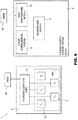
- the maintenance module 14 transmits the identifying data relative to the one or more replacement mechanical components C S1 -C S5 to the flight configuration module 10. Thereafter, the flight configuration module 10 stores the data received by the maintenance module 14, so as to store the data relative to a new flight configuration (shown schematically in figure 6 and indicated with reference numeral 169) mounted on the aircraft 5.
- figures 6 and 7 show, respectively, the flight system 1 with the new flight configuration 169 and the relative table stored in the flight configuration module 10 of the GLSS 3; in particular, in figures 6 and 7 it is considered that the rotary mechanical component Ci has been replaced with the replacement mechanical component Csi and that the relative identifying data have been stored, for example, in tabular format in the GLSS 3 ( figure 7 ).
- the PMDS 20 is connected to the data downloading module 12 of the GLSS 3, so as to be able to receive the data relative to the new flight configuration 169; thereafter, the PMDS 20 is updated by the GLSS 3.
- the GLSS 3 transmits and overwrites the identifying data of the flight configuration 9 with the data relative to the new flight configuration 169.
- steps 80-120 of the process illustrated in figure 3 are repeated every time the aircraft 5 operates.
- the initial data from which the OBC 8 starts are the identifying data relative to the one or more replacement mechanical components C S1 -C S5 .
- the present flight system 1 has critical elements.
- the identifying data in particular the first and second operating life data Tv 1, a -Tv 5, a , Tv 1, b -Tv 5, b , of the rotary mechanical components C 1 -C 5 , stored in the PMDS 20, can be corrupted or suffer from errors of various kinds.
- the identifying data of one or more rotary mechanical components C 1 -C 5 can be incorrect due to data transmission problems between the PDMS 20 and the OBC 8 or between the PMDS 20 and the GLSS 3.
- the OBC 8 will provide the PMDS 20 with incorrect second operating life data Tv 1, b -Tv 5, b (block 100 of figure 3 ).
- the second operating life data Tv 1 , b -Tv 5, b calculated by the OBC 8, already intrinsically incorrect, can be further corrupted in the transmission from the OBC 8 to the PMDS 20.
- the PMDS 20 transmits the aforementioned second operating life data Tv 1, b -Tv 5, b to the GLSS 3 for storage (block 110 of figure 3 ), the GLSS 3 will receive incorrect data and, therefore, can generate maintenance warning messages.
- the OBC 8 at the moment when it receives and processes the aforementioned identifying data (in particular the first or the second operating life data Tv 1 , a -Tv 5 , a , Tv 1, b -Tv 5, b ), will operate on incorrect data.
- the initialization process shown in figure 2 can also be subject to error.
- the ground tests of the rotary mechanical components C 1 -C 5 are sectorial (i.e. one or more rotary mechanical components C 1 -C 5 are activated)
- the OBC 8 of the aircraft 5 is not capable of providing totally correct first operating life data Tv 1, a -Tv 5, a
- the maintenance worker carries out an estimation of the aforementioned first operating life data Tv 1, a -Tv 5 , a . It derives from this that the rotary mechanical components C 1 -C 5 can have overestimated or underestimated first operating life data Tv 1, a -Tv 5, a with respect to their real values.
- a further error source is the storage error of the identifying data of the replacement rotary mechanical components C S1 -C S5 in the maintenance step.
- the maintenance worker can insert the aforementioned identifying data incorrectly into the maintenance module of the GLSS 3; for example, the maintenance worker may not insert the serial number of the replacement rotary mechanical component C S1 -C S5 or get the order of insertion of the aforementioned identifying data wrong.
- malfunctions in the feeding network of the aircraft 5, especially in the initialization or use step of the aircraft 5 itself, can introduce further errors.
- such malfunctions can, in some cases, lead to a reset of the OBC 8 for a certain time period; in such a time period, the OBC 8 is not capable of monitoring the first or the updated second operating life data Tv 1, a -Tv 5, a , Tv 1, b -Tv 5, b of the rotary mechanical components C 1 -C 5 or the number of ignitions N of the aircraft 5; therefore, the OBC 8 records a "dead" period, in which no data is acquired. Therefore, the initial or updated data recorded by the OBC 8 at the end of the initialization step or of the updating step of the data of the GLSS 3 (respectively, methods illustrated in figures 2 and 3 ) are incomplete.
- the errors listed above can lead to the GLSS 3 generating a premature maintenance warning message or, in some cases, a delayed one; moreover, if the errors in the data stored by the GLSS 3 are not identified and corrected, the GLSS 3 can generate further maintenance warning messages.
- the flight system 1 must be subjected to more frequent maintenance checks, in which it is necessary to verify the actual need to replace the one or more rotary mechanical components C 1 -C 5 imputed.
- the purpose of the present invention is to provide a method that at least partially overcomes the drawbacks of the prior art.
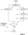
- Figure 8 schematically shows a block diagram of the present integrity verification method; in particular, the present integrity verification method is described in reference to the flight system 1 shown in figure 1 , assuming that the initialization method described earlier with reference to figure 2 has been carried out.
- the present method makes it possible to identify and correct errors in the data history of the ground logistic-support system (GLSS) 3, stored at the end of the updating method described with reference to figure 3 ; for the sake of simplicity of description and without any loss of generality, the present method is described with reference to the data history stored in the GLSS 3 at the end of the updating method described with reference to figure 3 .
- GLSS ground logistic-support system
- the data history of the GLSS 3 comprises the identifying data relative to each rotary mechanical component C 1 -C 5 , in particular the first and second operating life data Tv 1, b -Tv 5, b , Tv 1, b -Tv 5, b ; moreover, the data history of the GLSS 3 comprises the number of ignitions N of the aircraft 5 after a flight session (block 90 of figure 3 ), the latter comprising one or more flight operations (for example, flights in normal mode, flights in test mode and flights in emergency mode).
- the number of ignitions N is an indicator of the total number of flight operations carried out in the flight session considered; for example, as stated earlier, the number of ignitions N comprises the number of ignitions N a in normal mode, the number of ignitions N t in test mode and the number of ignitions N e in emergency mode.
- the present integrity verification method is preferably activated after the emission of a maintenance warning message of the GLSS 3 in order to verify whether such a warning is premature, delayed or appropriate; in particular, such an emergency procedure is carried out by a software installed on the GLSS 3.
- the aforementioned maintenance warning message has been generated after receiving and storing the second operating life data Tv 1, b -Tv 5, b (block 120 of figure 3 ) .
- the data history relative to the rotary mechanical components C 1 -C 5 mounted on the aircraft 5 is decoded by the present method.
- the data history is stored in the flight configuration module 10.
- the identifying data relative to each rotary mechanical component C 1 -C 5 are extracted, i.e. the part number P/N 1 -P/N 5 , the serial number S/N 1 -S/N 5 , the associated first and second operating life data Tv 1, a -Tv 5 , a , Tv 1, b -Tv 5, b and the maximum number of fatigue cycles N Cmax, 1 -N Cmax, 5 .
- the present method makes it possible to extract, for each rotary mechanical component C 1 -C 5 mounted on the aircraft 5, the second operating life data Tv 1, b -Tv 5, b , which have highlighted the need for a maintenance intervention since they have led to the generation of a maintenance warning message, from the data history previously decoded in block 200.
- the present method carries out the steps schematically indicated in blocks 204-208 of figure 8 and described hereinafter.
- block 204 starting from the data history decoded in block 200, makes it possible to extract the number of ignitions N, detected during the updating method of figure 3 from the OBC 8, from the data history of the GLSS 3.
- the numbers of ignitions N a , N e and N t are extracted.
- the plausible lifetime data T p1 -T p5 were previously introduced by a user and were determined through previous theoretical/practical experience (for example, system operation analysis); moreover, the plausible lifetime data T p1 -T p5 represent simulated operating life data, which are an indicator of an average activation time for each rotary mechanical component C 1 -C 5 relative to respective flight operations carried out by the aircraft 5. In other words, the plausible operating life data T p1 -T p5 represent average operating life data for each flight operation carried out in a flight session of the aircraft 5.
- the relative plausible operating life data T p1 -T p5 for each rotary mechanical component C i are: plausible operating life data in normal mode T pa1 -T pa5 ; plausible operating life data in test mode T pt1 -T pt5 ; and plausible operating life data in emergency mode T pe1 -T pe5 .
- a target operating life datum Tv ti is obtained from the total number of ignitions N and from the plausible operating life data T pi , obtained, respectively, in blocks 204 and 206.
- Tv ti target operating life datum
- the target operating life Tv t1 -Tv t5 is an estimation that suffers from errors deriving from the fact that the plausible lifetime data T p1 -T p5 are theoretical data.
- the estimation error is low, for example equal to a few hours (for example about ten hours, considering that each rotary mechanical component C 1 -C 5 can operate for a few thousand hours), and in any case is less than the error or the errors that may have modified or corrupted the identifying data stored in the data history of the GLSS 3.
- the present correction method carries out a comparison between the second operating life data Tv 1, b - Tv 5, b and the target operating life data Tv t1 -Tv t5 calculated in the previous block for every single rotary mechanical component C 1 -C 5 .
- the relative second updated operating life datum Tv 3, b and the target operating life datum Tv t, 3 are compared, so as to verify whether the second updated operating life datum Tv 3, b is plausible and, therefore, whether the intervention of a maintenance worker is actually required.
- the integrity verification method establishes that the data history relative to the rotary mechanical component C 1 -C 5 considered does not suffer from errors and, therefore, warns the user that the maintenance warning message generated both by the OBC 8 and by the GLSS 3 indicates an actual need to replace the aforementioned mechanical component C 1 -C 5 considered.
- the comparison gives a negative outcome; in particular, considering the flight configuration 9, there are divergences ⁇ Tv 1 - ⁇ Tv 5 relative to the rotary mechanical components C 1 -C 5 .
- the correction method establishes that the data history relative to the rotary mechanical component C 1 -C 5 considered suffers from one or more errors, and therefore the maintenance warning message is not reliable.
- the test carried out by the Applicant have highlighted that, although, as highlighted above, the target operating life data Tv t1 -Tv t5 suffers from an estimation error, such an estimation error is less than the divergence ⁇ Tv 1 - ⁇ Tv 5 , relative to each rotary mechanical component C 1 -C 5 , due to the error or the errors present in the data history of the GLSS 3.
- the divergence ⁇ Tv 1 - ⁇ Tv 5 is greater by an order of magnitude with respect to the estimation error.
- the present method can be applied in an analogous manner also in the case in which there are errors in the data history of the GLSS 3 due to errors in the insertion of the maintenance data of the replacement rotary mechanical components Csi mounted on the aircraft 5 after the maintenance process shown schematically in figure 5 .
- the present method is independent from the kind of error (or errors) that has afflicted the flight system 1; therefore, the present method is aimed at identifying and, subsequently, correcting the error (or the errors) present in the data history of the flight system 1.
- the present integrity verification method has many advantages.
- the present integrity verification method makes it possible to identify and correct one or more errors, due to different kinds of problems, which afflict the data history, in particular one or more identifying data (in detail, operating life data) relative to one or more rotary mechanical components mounted on the aircraft, stored in the GLSS and that have caused the generation of a maintenance warning message.
- the present method makes it possible to overwrite such operating life data with empirical operating life data, suffering from a lower estimation error with respect to the error or errors that afflict the data history of the GLSS; moreover, the present method makes it possible to verify whether the maintenance warning message is correct, notifying the user of the actual need to carry out a maintenance intervention on the one or more rotary mechanical components of the present aircraft.
- the present method makes it possible to resolve such errors in short time periods, limiting the idle time of the aircraft.
- the present method makes it possible to verify that it is actually necessary to carry out maintenance operations of the aircraft, the present method therefore makes it possible to limit the costs due to maintenance and to the replacement rotary mechanical components, as well as to limit the use of stored replacement rotary mechanical components.
- the present integrity verification method can be applied for any system subject to fatigue (for example, mechanical transmission systems).
- the input data, the integrity verification control logic components and the plausible values vary as a function of the type of system considered.
Landscapes
- Physics & Mathematics (AREA)
- General Physics & Mathematics (AREA)
- Engineering & Computer Science (AREA)
- Automation & Control Theory (AREA)
- Investigating Strength Of Materials By Application Of Mechanical Stress (AREA)
- Testing Of Devices, Machine Parts, Or Other Structures Thereof (AREA)
Abstract
Description
- This patent application claims priority from Italian patent application no.
102019000000617 filed on 15/01/2019 - The present invention relates to a method for verifying the integrity of operating life data of mechanical components of a system subject to fatigue. In particular, hereinafter reference will be made to rotary mechanical components of an aircraft, without however losing generality.
- As known, an aircraft comprises a set of mechanical components, in particular of the rotary type, like, for example gearboxes (GB), turbines and compressors.
- In use, the aircraft is actuated to carry out different flight sessions; in particular, each flight session comprises one or more flight operations, like for example, take-off, landing, cruising, test flight and/or emergency flight. Hereinafter, for the sake of simplicity and without any loss of generality, it will be considered that the aircraft carries out a single flight session, the latter comprising different flight operations.
- In each flight operation of the flight session, one or more rotary mechanical components are activated for respective one or more operating periods, i.e. time periods (measured, for example, in hours) that lapse between the ignition and the shutting down of the respective rotary mechanical component; in particular, each operating period is defined as fatigue cycle.
- In detail, each fatigue cycle depends on different factors, like, for example, the type of flight operation carried out, the environmental conditions (for example air pressure and temperature) and the interactions between the rotary mechanical components of the flight configuration during the performance of the one or more flight operations.
- Each rotary mechanical component can be activated many times in a single flight operation; therefore, each rotary mechanical component can carry out many fatigue cycles in a single flight operation of the flight session of the aircraft.
- At the end of the flight session, each rotary mechanical component has accumulated many hours of operation and, therefore, many fatigue cycles; in particular, the total number of hours of operation accumulated by each rotary mechanical component at the end of the flight session contributes to defining an operating life for each rotary mechanical component. In particular, the operating life of a rotary mechanical component is the number of hours of operation elapsed during the aforementioned flight session (and, therefore, the one or more flight operations) relative to the aforementioned rotary mechanical component; in greater detail, the operating life of a rotary mechanical component is an indicator of the number of fatigue cycles carried out in the aforementioned flight session of the aircraft.
- Since the aircraft is subjected to many flight sessions of the type described earlier, the number of hours of operation (and, therefore, the number of fatigue cycles and the operating life) of each rotary mechanical component of the flight configuration increases in every flight session.
- Each rotary mechanical component is capable of operating for a maximum number of hours of operation, i.e. a maximum number of fatigue cycles, beyond which the aforementioned rotary mechanical component must be replaced for safety reasons. Therefore, the rotary mechanical component has a maximum operating life.
-
Figure 1 schematically shows aflight apparatus 1 comprising a ground logistic-support system (GLSS) 3 and anaircraft 5. - In particular, the
aircraft 5 comprises: aflight configuration 9, which, for the sake of simplicity, comprises only m rotary mechanical components Ci (for example, five shown infigure 1 and indicated hereinafter with reference symbols C1-C5), in which i is an integer comprised between 1 and m. - The
aircraft 5 also comprises an on-board computer (OBC) 8, coupled to theflight configuration 9; in particular, the OBC 8 is adapted for controlling the flight configuration 9 (in particular, the rotary mechanical components C1-C5) during one or more flight operations carried out in one or more flight sessions of theaircraft 5. Moreover, the OBC 8 is adapted for determining and storing flight data relative to the rotary mechanical components C1-C5 after having carried out one or more flight sessions; in detail, the flight data comprise, for example: the hours of operation relative to each rotary mechanical component C1-C5; and a number of ignitions N of theaircraft 5. - In particular, the number of ignitions N represents the number of times in which the
aircraft 5 is controlled to carry out any flight operation; in other words, the number of ignitions N is an indicator of the total number of flight operations carried out by theaircraft 5. For example, theaircraft 5 can operate in normal mode for a number of ignitions Na; in test mode for a number of ignitions Nt; and in emergency mode for a number of ignitions Ne. Consequently, theaircraft 5 carries out Na flight operations in normal mode, Nt flight operations in test mode and Ne flight operations in emergency mode. Moreover, the number of ignitions N is defined as the sum of the number of ignitions Na, Nt and Ne; in addition, the number of ignitions N, as well as the ignition numbers Na, Nt and Ne increases after each flight operation carried out by theaircraft 5. - The GLSS 3 comprises many data storage modules, adapted for receiving and storing data relative to the rotary mechanical components C1-C5 of the
aircraft 5; in particular, the GLSS 3 offigure 1 includes: anaircraft configuration module 10, comprising identifying data (for example, part number, serial number, hours of operation and maximum number of fatigue cycles) relative to the rotary mechanical components C1-C5; adata downloading module 12 adapted for receiving and decoding the flight data relative to theflight configuration 9 after every flight session carried out by theaircraft 5; and amaintenance module 14, adapted for storing maintenance data (for example, serial number and hours of operation) of replaced rotary mechanical components that, when mounted instead of the corresponding rotary mechanical components C1-C5 in maintenance step, modify theflight configuration 9. - A Portable Maintenance Data Storage (PMDS) 20 can be coupled to the
data downloading module 12 of the GLSS 3 and to the OBC 8 of theaircraft 5; for example, the PMDS 20 is a cassette storage device. Moreover, the PMDS 20 is adapted for storing the identifying data of the rotary mechanical components C1-C5 and the relative flight data after the one or more flight sessions, as well as transmitting such flight data to the GLSS 3 (in particular, to the data downloading module 12). - In greater detail, the
PMDS 20 is initialized according to the method illustrated infigure 2 and described hereinafter. - Once the
flight configuration 9 is installed on theaircraft 5, the PMDS 20 is connected to a processor (not shown), through which a user (for example, a maintenance worker) inserts the identifying data relative to the rotary mechanical components C1-C5 of the flight configuration 9 (block 30). - In general, the identifying data relative to each rotary mechanical component Ci comprise fixed data and variable data. In particular, the fixed data comprise, for example: a part number P/Nj (in which j is an integer comprised between 1 and k, where k is an integer, less than m), indicating a category (or series) to which the aforementioned rotary mechanical component Ci belongs; a serial number S/Ni, indicating a number identifying the aforementioned rotary mechanical component Ci; and maximum number of fatigue cycles NCmax, i. Moreover, the variable data comprise an initial operating life datum Tv0, i (if present, like, for example, in the case of reconditioned rotary mechanical components), indicating the hours of operation elapsed of the relative rotary mechanical component Ci.
- In greater detail, in the insertion step of the identifying data, the maintenance worker associates one or more serial numbers S/Ni to each part number P/Nj; in particular, rotary mechanical components Ci of the same category have the same part number P/Nj but a different serial number S/Ni. Therefore, a part number P/Nj and one or more serial numbers S/Ni relative to one or more rotary mechanical components Ci of the same category directly correspond to one another.
- Moreover, the maintenance worker uniquely associates each serial number S/Ni with data relative to the operation of each rotary mechanical component Ci, in particular initial operating life data Tv0, i and maximum number of fatigue cycles NCmax, i.
- Therefore, at the end of the insertion step of the identifying data, each rotary mechanical component Ci is identified with a relative part number P/Nj, a relative serial number S/Ni, relative initial operating life data Tv0, i and relative number of fatigue cycles NCmax,i.
- Consequently, with reference to
figure 1 , each rotary mechanical component C1-C5 is characterised by respective part numbers P/N1-P/N3, respective serial numbers S/N1-S/N5, respective initial operating life data Tv0, 1- Tv0, 5 and respective maximum numbers of fatigue cycles NCmax, 1-NCmax, 5. Moreover, theflight configuration module 10 stores such identifying data for example in table format, as shown schematically infigure 4A . - At the end of the step described with reference to
block 30, the PMDS 20 has stored the identifying data (in particular, the hours of operation) relative to theflight configuration 9 of theaircraft 5. - Thereafter,
block 40, the PDMS 20 is disconnected from the GLSS 3 and connected to the OBC 8 of theaircraft 5. Here, the PDMS 20 transmits the identifying data of theflight configuration 9 to the OBC 8, which receives them and stores them in an internal memory (not shown). Such identifying data stored in the OBC 8 constitute the starting data for the subsequent operations of the initialisation method, described hereinafter. - In particular,
block 50, the maintenance worker carries out one or more ground tests of theaircraft 5. In particular, hereinafter, it will be considered that the one or more ground tests are followed for some rotary mechanical components C1-C5, for example the rotary mechanical components C1-C4, defined hereinafter as rotary mechanical components under examination C1-C4; in greater detail, as an example, the rotary mechanical components under examination C1-C4 are, respectively, the right Air Turbine Starter Motor (ATSM) C1, the right GB C2, the left ATSM C3 and the left GB C4. Moreover, it should be noted that, in the example considered, the right ATSM Ci and the right GB C2 form a first pair and operate jointly when the right motor is started; similarly, the left ATSM C3 and the left GB C4 form a second pair and operate jointly when the aforementioned left motor is started. - Again with reference to
block 50, in a first step, the one or more ground tests are, for example, carried out for the first pair C1-C2. In particular, the maintenance worker interacts with the OBC 8, so that the latter sends an activation command to the right motor of theaircraft 5; thereafter, the maintenance worker tests the first pair Ci-C2 carrying out one or more ground tests, so as to verify that it operates correctly. - If the first pair C1-C2 has operated correctly, the maintenance worker interacts with the OBC 8 so as to send a deactivation command to the right motor. Differently, if the maintenance worker has encountered an anomaly in the operation of the first pair C1-C2, the right motor is deactivated through a command coming from the OBC 8 and the maintenance worker takes care of replacing both of the rotary mechanical components under examination C1, C2 of the first pair C1-C2. Alternatively, if only one of the rotary mechanical components C1, C2 of the first pair C1-C2 is not operating, the maintenance worker replaces the defective rotary mechanical component.
- Subsequently, in an analogous way to what has been described earlier, the maintenance worker carries out one or more ground tests for the second pair C3-C4. In particular, the maintenance worker interacts with the OBC 8, so that the latter sends an activation command to the left motor of the
aircraft 5; thereafter, the maintenance worker tests the second pair C3-C4 carrying out one or more ground tests, so as to verify that it operates correctly. - In a manner similar to what has been discussed with reference to the first pair C1-C2, if the second pair C3-C4 has operated correctly, the maintenance worker interacts with the
OBC 8 so as to send a deactivation command to the left motor. Differently, if the maintenance worker has encountered an anomaly in the operation of the second pair C3-C4, the right motor is deactivated through a command coming from the OBC 8 and the maintenance worker takes care of replacing both of the rotary mechanical components under examination C3, C4 of the second pair C3-C4. Alternatively, if only one of the rotary mechanical components C3, C4 of the second pair C3-C4 is not operating, the maintenance worker replaced the defective rotary mechanical component. - At the end of the first and second step, the maintenance worker has been able to verify whether the rotary mechanical components under examination C1-C4 operate correctly in the activation step. Such a verifying operation can be extended, without any loss of generality, also to the rotary mechanical component C5 of the
flight configuration 9, so that it is also tested before the actual use of theaircraft 5. - Therefore, in general, the one or more ground tests are aimed at testing the operation of single rotary mechanical components C1-C5 o, in some cases, of groups of rotary mechanical components C1-C5 belonging to the
flight configuration 9, so as to verify the correct operation thereof. - Moreover, during the one or more ground tests, each rotary mechanical component C1-C5 carries out one or more fatigue cycles, which are monitored by the OBC 8 and contribute to increasing the number of hours of operation, as well as the initial operating life data Tv0, 1-Tv0, 5 of the respective rotary mechanical component C1-C5.
- At the end of the one or more ground tests,
block 60, the OBC 8 updates the initial operating life data Tv0, 1-Tv0, 5 based on the one or more fatigue cycles carried out in the previous block. At the end of the flight operations, the OBC 8 has stored first operating life data Tvi, a, which are determined based on the hours of operation elapsed in the previous block; in detail, for theflight configuration 9, there are first operating life data Tv1, a-Tv5, a., forming part of the variable data of the identifying data of the components C1-C5. In particular, the first operating life data Tv1, a-Tv5, a comprise operating life data relative to different operating modes of theaircraft 5; therefore, for example, the first operating life data Tv1, a-Tv5, a comprise operating life data in normal, test and emergency conditions. Moreover, the first operating life data Tv1, a-Tv5, a comprise operating life data relative to different operating conditions of theaircraft 5, like, for example, operating life data in normal and high-temperature conditions. - Thereafter, the first operating life data Tv1, a-Tv5, a are transmitted from the OBC 8 to the PMDS 20 (block 60) . Therefore, the first operating life data Tv1, a-Tv5, a are stored in the PDMS 20; in this way, the initial operating life data Tv0, 1- Tv0, 5, previously stored in the PMDS 20 in the step illustrated in
block 30, are overwritten with the first operating life data Tv1, a-Tv5, a. Then, the PDMS 20 is disconnected from the OBC 8. - At the end of the process shown in
figure 2 , theaircraft 5 and the PMDS 20, containing the updated identifying data (in particular, the first operating life data Tv1, a-Tv5, a) relative to theflight configuration 9, mounted on theaircraft 5, can be delivered to a user that uses theaircraft 5. -
Figure 3 schematically shows a block diagram of an updating method of the identifying data (in particular, of the first operating life data Tv1, a-Tv5, a) stored in the PMDS 20 after a flight session carried out by theaircraft 5. In particular, the steps shown in the block diagram offigure 3 are carried out after the initialization method of thePMDS 20 shown earlier infigure 2 ; therefore, the block diagram offigure 3 shows steps in which theaircraft 5 is used for the first time by the user that uses it and for a single flight session, the latter comprising one or more flight tests. - Initially,
block 70, the PMDS 20 is connected to the GLSS 3, in particular at thedata downloading module 12. Here, the PMDS 20 transmits the identifying data (in particular, the updated operating life data Tv1, a-Tv5, a) relative to theflight configuration 9 to the GLSS 3; in particular, the GLSS 3 acquires such identifying data at thedata downloading module 12. Thereafter, the identifying data thus received are transmitted to theflight configuration module 10, where they are stored. - In particular, the identifying data are stored in the
flight configuration module 10, for example, in tabular format, as shown for example infigure 4B . - Hereinafter, reference will be made to such identifying data, in particular the first operating life data Tv1, a-Tv5, a, as initial data.
- After the storage of the initial data in the
GLSS 3, block 80, thePMDS 20 is disconnected from theGLSS 3 and subsequently connected to theOBC 8 of theaircraft 5. In particular, similarly to what has been described atblock 70, thePMDS 20 transmits the initial data to theOBC 8, which stores them in the internal memory (not shown). The internal memory of theOBC 8, similarly to theGLSS 3, can store the initial data, for example, in tabular format as shown infigure 4B . - Thereafter, block 90, the
aircraft 5 is actuated so as to carry out the one or more flight operations in the flight session. - In particular, the
aircraft 5 is activated for the number of ignitions N; therefore, for example, for the number of ignitions Nt to carry out test flights, for the number of ignitions Na to carry out flights in normal conditions and for the number of ignitions Ne to carry out emergency flights; relative to each flight operation, theOBC 8 monitors the hours of operation of each rotary mechanical component C1-C5 activated during the aforementioned flight operations. In particular, the monitoring of the hours of operation of the rotary mechanical components C1-C5 is carried out through a plurality of sensors (not shown), like, for example phonic wheels adapted for providing a signal in frequency proportional to the rotation speed, forming part of theaircraft 5. - Moreover, the
OBC 8 records the number of ignitions N of the different flight operations of theaircraft 5 through relative counters (not shown), also forming part of theaircraft 5; for example, theOBC 8 records: the number of ignitions Na in normal mode; the number of ignitions Nt in test mode; and the number of ignitions Ne in emergency mode. - At the end of the flight operations, block 100, the
OBC 8 determines the total number of hours of operation of each rotary mechanical component C1-C5 and stores it; moreover, theOBC 8 stores the number of ignitions N (and, therefore, the numbers of ignitions Na, Nt and Ne). - In other words, at the end of the flight session of
block 90, the first operating life data Tvi, a are overwritten with second operating life data Tvi, b, obtained after the one or more flight operations ofblock 90 and forming part of the variable data of the aforementioned identifying data of the components Ci. In particular, for theflight configuration 9, there are second operating life data Tv1, b-Tv5, b. Therefore, theOBC 8 stores updated identifying data (hereinafter defined as updated data), comprising the second operating life data Tv1, b-Tv5, b. - Similarly to what has been discussed earlier, the second operating life data Tv1, b-Tv5, b also comprise data relative to the rotary mechanical components Ci in different operating conditions of the
aircraft 5; therefore, for example, the second operating life data Tv1, b-Tv5, b are given by the sum of operating life data in normal mode Tvnorm, 1-Tvnorm, 5, operating life data in test mode Tvt, 1-Tvt, 5 and operating life data in emergency mode Tve, 1-TVe, 5. - Thereafter, the updated data are transmitted to the
PMDS 20, so that, once received by thePMDS 20, the updated data, calculated by theOBC 8, overwrite the initial data stored in thePMDS 20. In other words, the initial data (in particular, the first operating life data Tv1, a-Tv5, a) in thePMDS 20 are overwritten with the updated data (in particular, the second operating life data Tv1, b-Tv5, b). - Thereafter, block 110, the
PMDS 20 is disconnected from theOBC 8 of theaircraft 5 and subsequently connected to theGLSS 3. In particular, thePMDS 20 transmits the updated data, received in the previous block, to the GLSS 3 (in particular, at the data downloading module 12); once received, thedata downloading module 12 transmits the aforementioned updated data to theflight configuration module 10. - Then, block 120, the identifying data relative to the rotary mechanical components C1-C5, stored earlier in the GLSS 3 (i.e. the initial data), and the identifying data received by the data downloading module 12 (i.e. the updated data) are present in the
flight configuration module 10; for example, the updated data are stored in theGLSS 3 in tabular format, as shown schematically infigure 4C . Alternatively, in particular the first and the second operating life data Tv1, a-Tv5, a, Tv1, b-Tv5, b are represented in graph form, for example with curvilinear graphs. Moreover, similarly to the first operating life data Tv1, a-Tv5, a, theGLSS 3 stores each second operating life datum Tv1, b-Tv5, b of each rotary mechanical component C1-C5, associating it uniquely to the remaining identifying data relative to the same rotary mechanical component C1-C5 (in particular, between part number P/N1-P/N3, serial number S/N1-S/N5 and the first operating life data Tv1, a-Tv5, a) ; indeed, the relationship between the identifying data is maintained. - At the end of the process illustrated in
figure 3 , theGLSS 3 comprises a data history, containing the initial data (in particular, the first operating life data Tv1, a-Tv5, a) and the data relative to the first use of the aircraft 5 (in particular, the second operating life data Tv1, b-TV5, b). - In addition, the second operating life data Tv1, b-Tv5, b constitute the new initial data from which to start for a subsequent flight session; therefore, the method illustrated in
figure 3 is repeated (in particular, steps 80-120) for every flight session of theaircraft 5. Consequently, at every flight session of theaircraft 5, the identifying data (in particular, the second operating life data Tv1, b-Tv5, b) of the rotary mechanical components C1-C5 are updated at every iteration; such a procedure is repeated until the maximum number of fatigue cycles NCmax, 1-NCmax, 5 of the one or more rotary mechanical components C1-C5 is reached. Once the maximum number of fatigue cycles NCmax, 1-NCmax, 5 has been reached, theGLSS 3 generates a maintenance warning message; in particular, the maintenance warning message warns the user of the need to replace one or more rotary mechanical components C1-C5 of theflight configuration 9, in particular indicating which of the rotary mechanical components C1-C5 must be replaced. -
Figure 5 schematically shows a maintenance method carried out by a maintenance worker after the generation of a maintenance warning message by theGLSS 3. In particular, the maintenance warning message notifies the user that uses theaircraft 5 of the need to replace one or more rotary mechanical components Ci, due to the relative maximum numbers of fatigue cycles NCmax, 1-NCmax, 5 having been exceeded; in particular, the warning takes place, for example, through a display (not shown), forming part of theGLSS 3. - In particular, block 130, the maintenance worker takes care of replacing the one or more rotary mechanical components Ci indicated in the maintenance warning message of the
GLSS 3 with one or more replacement rotary mechanical components Csi; in detail, in the case of theflight configuration 9 offigure 1 , there are one or more replacement components CS1-CS5. In particular, the one or more replacement rotary components CS1-CS5 share the same part number P/N1-P/N3 as the rotary mechanical components C1-C5 to be replaced. For example, if the rotary mechanical component Ci must be replaced, the maintenance worker will mount a rotary mechanical component Csi, the part number P/N1 remains unchanged; differently, the one or more replacement rotary mechanical components CS1-CS5 have relative serial numbers S/NS1-S/NS5, initial operating life data TvS0, 1-TVS0, 5 and number of fatigue cycles NCmax, s1-NCmax, S5. - Thereafter, block 140, the maintenance worker takes care of inserting the data relative to the one or more replacement rotary mechanical components CS1-CS5 in the
maintenance module 14 of theGLSS 3. After the insertion of such data, theGLSS 3 takes care of updating the data stored in theflight configuration module 10 based on the data stored in themaintenance module 14, so as to integrate the data relative to the one or more replacement rotary mechanical components CS1-CS5. - In particular, the
maintenance module 14 transmits the identifying data relative to the one or more replacement mechanical components CS1-CS5 to theflight configuration module 10. Thereafter, theflight configuration module 10 stores the data received by themaintenance module 14, so as to store the data relative to a new flight configuration (shown schematically infigure 6 and indicated with reference numeral 169) mounted on theaircraft 5. In particular,figures 6 and7 show, respectively, theflight system 1 with thenew flight configuration 169 and the relative table stored in theflight configuration module 10 of theGLSS 3; in particular, infigures 6 and7 it is considered that the rotary mechanical component Ci has been replaced with the replacement mechanical component Csi and that the relative identifying data have been stored, for example, in tabular format in the GLSS 3 (figure 7 ). - Thereafter, block 150, the
PMDS 20 is connected to thedata downloading module 12 of theGLSS 3, so as to be able to receive the data relative to thenew flight configuration 169; thereafter, thePMDS 20 is updated by theGLSS 3. In particular, theGLSS 3 transmits and overwrites the identifying data of theflight configuration 9 with the data relative to thenew flight configuration 169. - At the end of the maintenance procedure indicated above, steps 80-120 of the process illustrated in
figure 3 are repeated every time theaircraft 5 operates. In particular, after the replacement of one or more rotary mechanical components C1-C5, the initial data from which theOBC 8 starts are the identifying data relative to the one or more replacement mechanical components CS1-CS5. - However, the
present flight system 1 has critical elements. - In detail, the identifying data, in particular the first and second operating life data Tv1, a-Tv5, a, Tv1, b-Tv5, b, of the rotary mechanical components C1-C5, stored in the
PMDS 20, can be corrupted or suffer from errors of various kinds. - In particular, the identifying data of one or more rotary mechanical components C1-C5 can be incorrect due to data transmission problems between the
PDMS 20 and theOBC 8 or between thePMDS 20 and theGLSS 3. - In greater detail, if the data transmission error occurs between the
PMDS 20 and theOBC 8 before the flight operations are carried out (block 80 offigure 3 ), the initial data used by theOBC 8 for monitoring the rotary mechanical components C1-C5 on theaircraft 5 suffer from such a transmission error; therefore, at the end of the flight operations, theOBC 8 will provide thePMDS 20 with incorrect second operating life data Tv1, b-Tv5, b (block 100 offigure 3 ). Moreover, the second operating life data Tv1, b-Tv5, b calculated by theOBC 8, already intrinsically incorrect, can be further corrupted in the transmission from theOBC 8 to thePMDS 20. - Consequently, when the
PMDS 20 transmits the aforementioned second operating life data Tv1, b-Tv5, b to theGLSS 3 for storage (block 110 offigure 3 ), theGLSS 3 will receive incorrect data and, therefore, can generate maintenance warning messages. - Similarly, if the data transmission error occurs between the
PMDS 20 and theGLSS 3 before the flight operations are carried out (blocks 70 or 110 offigure 3 ), the identifying data stored in thePMDS 20 suffer from error; therefore, theOBC 8, at the moment when it receives and processes the aforementioned identifying data (in particular the first or the second operating life data Tv1, a-Tv5, a, Tv1, b-Tv5, b), will operate on incorrect data. - In addition, the initialization process shown in
figure 2 can also be subject to error. In particular, since the ground tests of the rotary mechanical components C1-C5 are sectorial (i.e. one or more rotary mechanical components C1-C5 are activated), theOBC 8 of theaircraft 5 is not capable of providing totally correct first operating life data Tv1, a-Tv5, a, since only part of theaircraft 5 is activated in order to ensure the operation of the rotary mechanical component C1-C5 to be tested; therefore, the maintenance worker carries out an estimation of the aforementioned first operating life data Tv1, a-Tv5, a. It derives from this that the rotary mechanical components C1-C5 can have overestimated or underestimated first operating life data Tv1, a-Tv5, a with respect to their real values. - Moreover, a further error source is the storage error of the identifying data of the replacement rotary mechanical components CS1-CS5 in the maintenance step. In particular, the maintenance worker can insert the aforementioned identifying data incorrectly into the maintenance module of the
GLSS 3; for example, the maintenance worker may not insert the serial number of the replacement rotary mechanical component CS1-CS5 or get the order of insertion of the aforementioned identifying data wrong. - In addition, malfunctions in the feeding network of the
aircraft 5, especially in the initialization or use step of theaircraft 5 itself, can introduce further errors. In particular, such malfunctions can, in some cases, lead to a reset of theOBC 8 for a certain time period; in such a time period, theOBC 8 is not capable of monitoring the first or the updated second operating life data Tv1, a-Tv5, a, Tv1, b-Tv5, b of the rotary mechanical components C1-C5 or the number of ignitions N of theaircraft 5; therefore, theOBC 8 records a "dead" period, in which no data is acquired. Therefore, the initial or updated data recorded by theOBC 8 at the end of the initialization step or of the updating step of the data of the GLSS 3 (respectively, methods illustrated infigures 2 and 3 ) are incomplete. - The errors listed above can lead to the
GLSS 3 generating a premature maintenance warning message or, in some cases, a delayed one; moreover, if the errors in the data stored by theGLSS 3 are not identified and corrected, theGLSS 3 can generate further maintenance warning messages. In other words, theflight system 1 must be subjected to more frequent maintenance checks, in which it is necessary to verify the actual need to replace the one or more rotary mechanical components C1-C5 imputed. - The purpose of the present invention is to provide a method that at least partially overcomes the drawbacks of the prior art.
- According to the present invention a method for verifying the integrity of operating life data of mechanical components of a system subject to fatigue is made, as defined in the attached claims.
- For better understanding of the present invention, a preferred embodiment thereof is now described, purely as a non-limiting example, with reference to the attached drawings, in which:
-
figure 1 schematically shows a flight system; -
figure 2 schematically shows a block diagram of an initialization method of a memory element of the system offigure 1 ; -
figure 3 schematically shows a block diagram of a data updating method of the flight system offigure 1 ; -
figures 4A-4C show a portion of the flight system offigure 1 in different operating stages, as an example; -
figure 5 schematically shows a block diagram of a maintenance method of an aircraft of the flight system offigure 1 ; and -
figure 6 schematically shows the flight system offigure 1 with flight configuration modified according to the method offigure 5 ; -
figure 7 shows a portion of the flight system offigure 6 , as an example; and -
figure 8 schematically shows a block diagram of the present error correction method. -
Figure 8 schematically shows a block diagram of the present integrity verification method; in particular, the present integrity verification method is described in reference to theflight system 1 shown infigure 1 , assuming that the initialization method described earlier with reference tofigure 2 has been carried out. - Moreover, the present method makes it possible to identify and correct errors in the data history of the ground logistic-support system (GLSS) 3, stored at the end of the updating method described with reference to
figure 3 ; for the sake of simplicity of description and without any loss of generality, the present method is described with reference to the data history stored in theGLSS 3 at the end of the updating method described with reference tofigure 3 . In particular, as described earlier, the data history of theGLSS 3 comprises the identifying data relative to each rotary mechanical component C1-C5, in particular the first and second operating life data Tv1, b-Tv5, b, Tv1, b-Tv5, b; moreover, the data history of theGLSS 3 comprises the number of ignitions N of theaircraft 5 after a flight session (block 90 offigure 3 ), the latter comprising one or more flight operations (for example, flights in normal mode, flights in test mode and flights in emergency mode). In particular, the number of ignitions N is an indicator of the total number of flight operations carried out in the flight session considered; for example, as stated earlier, the number of ignitions N comprises the number of ignitions Na in normal mode, the number of ignitions Nt in test mode and the number of ignitions Ne in emergency mode. - In addition, the present integrity verification method is preferably activated after the emission of a maintenance warning message of the
GLSS 3 in order to verify whether such a warning is premature, delayed or appropriate; in particular, such an emergency procedure is carried out by a software installed on theGLSS 3. Moreover, in order to facilitate the understanding of the present invention, it is considered that the aforementioned maintenance warning message has been generated after receiving and storing the second operating life data Tv1, b-Tv5, b (block 120 offigure 3 ) . - Initially, block 200, the data history relative to the rotary mechanical components C1-C5 mounted on the
aircraft 5 is decoded by the present method. In particular, the data history is stored in theflight configuration module 10. After the decoding operations, the identifying data relative to each rotary mechanical component C1-C5 are extracted, i.e. the part number P/N1-P/N5, the serial number S/N1-S/N5, the associated first and second operating life data Tv1, a-Tv5, a, Tv1, b-Tv5, b and the maximum number of fatigue cycles NCmax, 1-NCmax, 5. - Thereafter, in block 202 the present method makes it possible to extract, for each rotary mechanical component C1-C5 mounted on the
aircraft 5, the second operating life data Tv1, b-Tv5, b, which have highlighted the need for a maintenance intervention since they have led to the generation of a maintenance warning message, from the data history previously decoded inblock 200. - At the same time as the step of block 202, the present method carries out the steps schematically indicated in blocks 204-208 of
figure 8 and described hereinafter. - In particular, block 204, starting from the data history decoded in
block 200, makes it possible to extract the number of ignitions N, detected during the updating method offigure 3 from theOBC 8, from the data history of theGLSS 3. - As an example, the numbers of ignitions Na, Ne and Nt, respectively relative to flight operations in normal mode, emergency mode and test mode, are extracted.
- Thereafter, block 206, plausible operating life data Tpi, relative to the rotary mechanical components Ci and stored in the
GLSS 3 are selected; in particular, for theflight configuration 9 offigure 1 , there are plausible lifetime data Tp1-Tp5. - In greater detail, the plausible lifetime data Tp1-Tp5 were previously introduced by a user and were determined through previous theoretical/practical experience (for example, system operation analysis); moreover, the plausible lifetime data Tp1-Tp5 represent simulated operating life data, which are an indicator of an average activation time for each rotary mechanical component C1-C5 relative to respective flight operations carried out by the
aircraft 5. In other words, the plausible operating life data Tp1-Tp5 represent average operating life data for each flight operation carried out in a flight session of theaircraft 5. For example, supposing that theaircraft 5 carries out flight operations in normal mode, in test mode and in emergency mode, the relative plausible operating life data Tp1-Tp5 for each rotary mechanical component Ci are: plausible operating life data in normal mode Tpa1-Tpa5; plausible operating life data in test mode Tpt1-Tpt5; and plausible operating life data in emergency mode Tpe1-Tpe5. - Thereafter, block 208, a target operating life datum Tvti, relative to each rotary mechanical component Ci under examination, is obtained from the total number of ignitions N and from the plausible operating life data Tpi, obtained, respectively, in
blocks flight configuration 9, there are target operating life data Tvt1-Tvt5. - In particular, the target operating life datum Tvti is calculated according to the equation (1):

aircraft 5; and i is an integer comprised between 1 and m, relative to the rotary mechanical components Ci. Therefore, relative to theflight configuration 9, the indicator r comprises the identifiers a, e, t relative to the normal, test and emergency flight modes; and the indicator i is comprised between 1 and 5, so as to identify the rotary mechanical components C1-C5. - In greater detail, the target operating life Tvt1-Tvt5 is an estimation that suffers from errors deriving from the fact that the plausible lifetime data Tp1-Tp5 are theoretical data. In any case, based on the tests carried out by the Applicant, the estimation error is low, for example equal to a few hours (for example about ten hours, considering that each rotary mechanical component C1-C5 can operate for a few thousand hours), and in any case is less than the error or the errors that may have modified or corrupted the identifying data stored in the data history of the
GLSS 3. - With reference to block 210, the present correction method carries out a comparison between the second operating life data Tv1, b- Tv5, b and the target operating life data Tvt1-Tvt5 calculated in the previous block for every single rotary mechanical component C1-C5. In other words, for example, for the rotary mechanical component C3, the relative second updated operating life datum Tv3, b and the target operating life datum Tvt, 3 are compared, so as to verify whether the second updated operating life datum Tv3, b is plausible and, therefore, whether the intervention of a maintenance worker is actually required.
- In detail, if the second operating life data Tv1, b-Tv5, b and the target operating life data Tvt1-Tvt5 are roughly equal (for example, the absolute value of the divergence ΔTvi, relative to each rotary mechanical component Ci, is less than a limit value), the integrity verification method establishes that the data history relative to the rotary mechanical component C1-C5 considered does not suffer from errors and, therefore, warns the user that the maintenance warning message generated both by the
OBC 8 and by theGLSS 3 indicates an actual need to replace the aforementioned mechanical component C1-C5 considered. - Alternatively, if the second operating life data Tv1, b- Tv5, b and the target operating life data Tvt1-Tvt5 are much different from one another (for example, the absolute value of the divergence ΔTvi, relative to each rotary mechanical component Ci, is above a limit value), the comparison gives a negative outcome; in particular, considering the
flight configuration 9, there are divergences ΔTv1- ΔTv5 relative to the rotary mechanical components C1-C5. In this case, the correction method establishes that the data history relative to the rotary mechanical component C1-C5 considered suffers from one or more errors, and therefore the maintenance warning message is not reliable. - After the comparison of
block 210, in the case of comparison with negative outcome, block 212, the second operating life datum Tv1, b- Tv5, b relative to the rotary mechanical component C1-C5 considered in the previous comparison (block 210) is replaced (for example, overwritten) with the target operating life datum Tvt1-Tvt5 previously calculated based on what is stated above. - The tests carried out by the Applicant have highlighted that, although, as highlighted above, the target operating life data Tvt1-Tvt5 suffers from an estimation error, such an estimation error is less than the divergence ΔTv1- ΔTv5, relative to each rotary mechanical component C1-C5, due to the error or the errors present in the data history of the
GLSS 3. For example, in some cases, the divergence ΔTv1- ΔTv5 is greater by an order of magnitude with respect to the estimation error. - The method described above is thus repeated for all of the rotary mechanical components C1-C5 of the flight configuration 9 (in particular, steps 202-212 of
figure 8 are repeated); in this way, once all of the rotary mechanical components C1-C5 have been verified and possible divergences ΔTv1- ΔTv5 have been eliminated (block 212), a user is capable of precisely discerning which among the rotary mechanical components C1-C5 indicated need a maintenance intervention. - The present method can be applied in an analogous manner also in the case in which there are errors in the data history of the
GLSS 3 due to errors in the insertion of the maintenance data of the replacement rotary mechanical components Csi mounted on theaircraft 5 after the maintenance process shown schematically infigure 5 . - The present method is independent from the kind of error (or errors) that has afflicted the
flight system 1; therefore, the present method is aimed at identifying and, subsequently, correcting the error (or the errors) present in the data history of theflight system 1. - The present integrity verification method has many advantages.
- In particular, the present integrity verification method makes it possible to identify and correct one or more errors, due to different kinds of problems, which afflict the data history, in particular one or more identifying data (in detail, operating life data) relative to one or more rotary mechanical components mounted on the aircraft, stored in the GLSS and that have caused the generation of a maintenance warning message. In particular, the present method makes it possible to overwrite such operating life data with empirical operating life data, suffering from a lower estimation error with respect to the error or errors that afflict the data history of the GLSS; moreover, the present method makes it possible to verify whether the maintenance warning message is correct, notifying the user of the actual need to carry out a maintenance intervention on the one or more rotary mechanical components of the present aircraft.
- Moreover, the present method makes it possible to resolve such errors in short time periods, limiting the idle time of the aircraft.
- In addition, since the present method makes it possible to verify that it is actually necessary to carry out maintenance operations of the aircraft, the present method therefore makes it possible to limit the costs due to maintenance and to the replacement rotary mechanical components, as well as to limit the use of stored replacement rotary mechanical components.
- Finally, it is clear that modifications and variants can be brought to the relative method described and illustrated here, without for this reason departing from the scope of protection of the present invention, as defined in the attached claims.
- For example, the present integrity verification method can be applied for any system subject to fatigue (for example, mechanical transmission systems). In this case, the input data, the integrity verification control logic components and the plausible values vary as a function of the type of system considered.
Claims (12)
- A method for verifying the integrity of operating life data of mechanical components (Ci, C1-C5, CS1-CS5) of a system subject to fatigue (5), said system subject to fatigue comprising an on-board computer, OBC, (8), configured to control said mechanical components, said system subject to fatigue being configured to carry out a set of operations comprising the steps of:receiving (80), from a portable memory device, PMDS - Portable Maintenance Data Storage, (20), which can be coupled to the on-board computer, OBC, first identifying data (S/Ni, P/Nj, NCmax, i, Tv1, a) relative to each of said mechanical components of the system subject to fatigue, wherein said first identifying data comprise fixed data (S/Ni, P/Nj, NCmax, i, Tv0, i) and first variable data (Tvi, a), said fixed data being associated with said first variable data and comprising maximum life data (NCmax, i) ;carrying out (90) at least one first operating session, said at least one operating session comprising at least one first operation;determining a first number of ignitions (N, Na, Nt, Ne) indicative of said at least one first operating session;determining, starting from said at least one first operating session, second identifying data (S/Ni, P/Nj, NCmax, i, Tv1, b) relative to each of said mechanical components of the system subject to fatigue, said second identifying data comprising said fixed data and second variable data (Tvi, b) determined following upon said at least one first operating session; andsending (100) said second identifying data and said first number of ignitions to said portable memory device , PMDS, (20) from said on-board computer, OBC,the method comprising the steps of:sending (110) said second identifying data and said first number of ignitions to a ground logistic-support system ,GLSS, (3) from said portable memory device, PMDS, which can be coupled to said ground logistic-support system ,GLSS, said ground logistic-support system, GLSS, comprising said first identifying data;storing (120), starting from said second identifying data, said second variable data and said first number of ignitions in said ground logistic-support system, GLSS, so as to determine a first data history; anddetermining that, if said second variable data are higher than said maximum life data, said first data history presents an error,the method being characterized in that it comprises the steps of:decoding (200), starting from said ground logistic-support system, GLSS, (3), said first data history regarding said mechanical components;acquiring (202), starting from said first data history decoded and for each of said mechanical components, said second variable data;acquiring (204), starting from said ground logistic-support system, GLSS, said first number of ignitions;determining reference data (Tp, i), indicative of each of said mechanical components and of said at least one first operation;determining (208), starting from said first number of ignitions and from said reference data (Tp, i), target operating life data (Tvt, i) for each of said mechanical components; andcomparing (210) said second variable data and said target operating life data for each of said mechanical components, wherein the present method further comprises the step of:determining that, if said second variable data and said target operating life data are comparable within a confidence interval, said second variable data and said first data history are correct;or the steps of:determining that, if said second variable data and said target operating life data are not comparable within said confidence interval, said second variable data and said first data history present an error; andoverwriting (212) said second variable data with said target operating life data in said first data history of said ground logistic-support system, GLSS.
- The method according to Claim 1, wherein said set of operations is carried out at least once.
- The method according to Claim 1, wherein said reference data (Tp, i) are average life data for each of said mechanical components (Ci, C1-C5, CS1-CS5) .
- The method according to Claim 3, wherein said data of target life (Tvt, i) are determined as product of said first number of ignitions (N, Na, Nt, Ne) and said reference data (Tp, i).
- The method according to Claim 1, wherein, prior to said step of receiving said first identifying data (S/Ni, P/Nj, NCmax, i, Tv0, i, Tvi, a), the method further comprises the steps of:storing (30), in said portable memory device, PMDS, (20), said fixed data (S/Ni, P/Nj, NCmax, i, Tv0, i) regarding said mechanical components (Ci, C1-C5, CS1-CS5) ;sending (40), from said portable memory device, PMDS, said fixed data to said on-board computer, OBC, (8); andstoring in said system subject to fatigue said fixed data that have been sent.
- The method according to Claim 5, wherein said system subject to fatigue is configured to carry out a second set of operations comprising the steps of:carrying out (50) at least one second operating session, said at least one second operating session comprising at least one second operation;determining, following said at least one second operating session, said first identifying data (S/Ni, P/Nj, NCmax, i, Tv0, i, Tvi, a) ;determining a second number of ignitions (N, Na, Nt, Ne) indicative of said at least one second operating session; andstoring (60) said first identifying data and said second number of ignitions in said system subject to fatigue.
- The method according to Claim 6, wherein said method further comprises the steps of:sending said first identifying data and said second number of ignitions to said portable memory device, PMDS, from said on-board computer, OBC, (8);storing said first identifying data and said second number of ignitions in said portable memory device, PMDS;sending (70), starting from said portable memory device, PMDS, said first identifying data (S/Ni, P/Nj, NCmax, i, Tv0, i, Tvi, a) and said second number of ignitions (N, Na, Nt, Ne) to said ground logistic-support system , GLSS, (3); and storing said first identifying data and said second number of ignitions in said ground logistic-support system, GLSS, so as to determine a second data history.
- The method according to Claim 7, wherein said first number of ignitions comprises said second number of ignitions.
- The method according to Claim 7, wherein said first data history of said ground logistic-support system, GLSS, (3) comprises said second data history.
- The method according to any one of the preceding claims, wherein said system subject to fatigue (5) is an aircraft.
- The method according to any one of the preceding claims, wherein said mechanical components (Ci, C1-C5, CS1-CS5) are rotary mechanical components.
- The method according to Claim 11, wherein said mechanical components (Ci, C1-C5, CS1-CS5) are air-turbine starting motors, ATSMs, and gearboxes, GBs.
Applications Claiming Priority (1)
| Application Number | Priority Date | Filing Date | Title |
|---|---|---|---|
| IT102019000000617A IT201900000617A1 (en) | 2019-01-15 | 2019-01-15 | METHOD FOR VERIFYING THE INTEGRITY OF OPERATIONAL LIFE DATA OF MECHANICAL COMPONENTS OF A SYSTEM SUBJECT TO FATIGUE |
Publications (2)
| Publication Number | Publication Date |
|---|---|
| EP3683642A1 true EP3683642A1 (en) | 2020-07-22 |
| EP3683642B1 EP3683642B1 (en) | 2023-03-01 |
Family
ID=66286591
Family Applications (1)
| Application Number | Title | Priority Date | Filing Date |
|---|---|---|---|
| EP20152073.1A Active EP3683642B1 (en) | 2019-01-15 | 2020-01-15 | Method for measuring fatigue for mechanical components of an aircraft |
Country Status (3)
| Country | Link |
|---|---|
| EP (1) | EP3683642B1 (en) |
| ES (1) | ES2942909T3 (en) |
| IT (1) | IT201900000617A1 (en) |
Citations (2)
| Publication number | Priority date | Publication date | Assignee | Title |
|---|---|---|---|---|
| US20090306909A1 (en) * | 2005-04-20 | 2009-12-10 | Johannes Mattes | Method for evaluating measured values for identifying a material fatigue |
| US9260200B1 (en) * | 2014-11-07 | 2016-02-16 | International Business Machines Corporation | Metal fatigue analytics and alert systems |
-
2019
- 2019-01-15 IT IT102019000000617A patent/IT201900000617A1/en unknown
-
2020
- 2020-01-15 EP EP20152073.1A patent/EP3683642B1/en active Active
- 2020-01-15 ES ES20152073T patent/ES2942909T3/en active Active
Patent Citations (2)
| Publication number | Priority date | Publication date | Assignee | Title |
|---|---|---|---|---|
| US20090306909A1 (en) * | 2005-04-20 | 2009-12-10 | Johannes Mattes | Method for evaluating measured values for identifying a material fatigue |
| US9260200B1 (en) * | 2014-11-07 | 2016-02-16 | International Business Machines Corporation | Metal fatigue analytics and alert systems |
Also Published As
| Publication number | Publication date |
|---|---|
| EP3683642B1 (en) | 2023-03-01 |
| ES2942909T3 (en) | 2023-06-07 |
| IT201900000617A1 (en) | 2020-07-15 |
Similar Documents
| Publication | Publication Date | Title |
|---|---|---|
| JP4482206B2 (en) | Embedded engine diagnostic system | |
| CN110023862B (en) | Diagnostic device, diagnostic method, and computer-readable recording medium | |
| EP2287449B1 (en) | Gas turbine engine oil consumption monitoring system and method | |
| CN105593118B (en) | Method for diagnosing faults in auxiliary power units | |
| US20040176879A1 (en) | Transient fault detection system and method using Hidden Markov Models | |
| US7877636B2 (en) | System and method for detecting temporal relationships uniquely associated with an underlying root cause | |
| US10725463B1 (en) | High frequency sensor data analysis and integration with low frequency sensor data used for parametric data modeling for model based reasoners | |
| EP2390742B1 (en) | Monitoring engine usage | |
| CN111634160B (en) | Method for establishing communication connection with tire pressure monitoring system, device and electronic equipment thereof | |
| EP2384971A1 (en) | Method of determining a maneuver performed by an aircraft | |
| US20110004369A1 (en) | Method and System for Generating Electronic Documentation for Maintenance | |
| CN103154693A (en) | System for monitoring an engine test bed | |
| JP2015522747A (en) | Method and system for determining lifetime consumption of machine parts | |
| WO2013155161A1 (en) | Efficient health management, diagnosis and prognosis of a machine | |
| US10551818B2 (en) | Fault detection methods and systems | |
| US5689066A (en) | Method and apparatus for analyzing gas turbine pneumatic fuel system | |
| US20020194536A1 (en) | Printer diagnostics method | |
| EP3683642B1 (en) | Method for measuring fatigue for mechanical components of an aircraft | |
| EP3742359B1 (en) | Systems and methods for auxiliary power unit health indicator computation | |
| US20160332750A1 (en) | Aircraft active history memory module | |
| US20170038281A1 (en) | Method of predicting life of component of machine | |
| US20240262138A1 (en) | Tire internal pressure management device, tire internal pressure management program, and tire internal pressure management method | |
| CN111608804B (en) | Diagnostic test method and system for engine crankshaft/camshaft synchronous signal | |
| EP3303835B1 (en) | Method for windmill farm monitoring | |
| CN108803581B (en) | Fault remote diagnosis method based on expert template |
Legal Events
| Date | Code | Title | Description |
|---|---|---|---|
| PUAI | Public reference made under article 153(3) epc to a published international application that has entered the european phase |
Free format text: ORIGINAL CODE: 0009012 |
|
| STAA | Information on the status of an ep patent application or granted ep patent |
Free format text: STATUS: THE APPLICATION HAS BEEN PUBLISHED |
|
| AK | Designated contracting states |
Kind code of ref document: A1 Designated state(s): AL AT BE BG CH CY CZ DE DK EE ES FI FR GB GR HR HU IE IS IT LI LT LU LV MC MK MT NL NO PL PT RO RS SE SI SK SM TR |
|
| AX | Request for extension of the european patent |
Extension state: BA ME |
|
| STAA | Information on the status of an ep patent application or granted ep patent |
Free format text: STATUS: REQUEST FOR EXAMINATION WAS MADE |
|
| 17P | Request for examination filed |
Effective date: 20210121 |
|
| RBV | Designated contracting states (corrected) |
Designated state(s): AL AT BE BG CH CY CZ DE DK EE ES FI FR GB GR HR HU IE IS IT LI LT LU LV MC MK MT NL NO PL PT RO RS SE SI SK SM TR |
|
| GRAP | Despatch of communication of intention to grant a patent |
Free format text: ORIGINAL CODE: EPIDOSNIGR1 |
|
| STAA | Information on the status of an ep patent application or granted ep patent |
Free format text: STATUS: GRANT OF PATENT IS INTENDED |
|
| INTG | Intention to grant announced |
Effective date: 20220812 |
|
| GRAS | Grant fee paid |
Free format text: ORIGINAL CODE: EPIDOSNIGR3 |
|
| GRAA | (expected) grant |
Free format text: ORIGINAL CODE: 0009210 |
|
| STAA | Information on the status of an ep patent application or granted ep patent |
Free format text: STATUS: THE PATENT HAS BEEN GRANTED |
|
| AK | Designated contracting states |
Kind code of ref document: B1 Designated state(s): AL AT BE BG CH CY CZ DE DK EE ES FI FR GB GR HR HU IE IS IT LI LT LU LV MC MK MT NL NO PL PT RO RS SE SI SK SM TR |
|
| REG | Reference to a national code |
Ref country code: GB Ref legal event code: FG4D |
|
| REG | Reference to a national code |
Ref country code: CH Ref legal event code: EP Ref country code: AT Ref legal event code: REF Ref document number: 1551421 Country of ref document: AT Kind code of ref document: T Effective date: 20230315 |
|
| REG | Reference to a national code |
Ref country code: DE Ref legal event code: R096 Ref document number: 602020008350 Country of ref document: DE |
|
| REG | Reference to a national code |
Ref country code: IE Ref legal event code: FG4D |
|
| REG | Reference to a national code |
Ref country code: ES Ref legal event code: FG2A Ref document number: 2942909 Country of ref document: ES Kind code of ref document: T3 Effective date: 20230607 |
|
| REG | Reference to a national code |
Ref country code: LT Ref legal event code: MG9D |
|
| REG | Reference to a national code |
Ref country code: NL Ref legal event code: MP Effective date: 20230301 |
|
| PG25 | Lapsed in a contracting state [announced via postgrant information from national office to epo] |
Ref country code: RS Free format text: LAPSE BECAUSE OF FAILURE TO SUBMIT A TRANSLATION OF THE DESCRIPTION OR TO PAY THE FEE WITHIN THE PRESCRIBED TIME-LIMIT Effective date: 20230301 Ref country code: NO Free format text: LAPSE BECAUSE OF FAILURE TO SUBMIT A TRANSLATION OF THE DESCRIPTION OR TO PAY THE FEE WITHIN THE PRESCRIBED TIME-LIMIT Effective date: 20230601 Ref country code: LV Free format text: LAPSE BECAUSE OF FAILURE TO SUBMIT A TRANSLATION OF THE DESCRIPTION OR TO PAY THE FEE WITHIN THE PRESCRIBED TIME-LIMIT Effective date: 20230301 Ref country code: LT Free format text: LAPSE BECAUSE OF FAILURE TO SUBMIT A TRANSLATION OF THE DESCRIPTION OR TO PAY THE FEE WITHIN THE PRESCRIBED TIME-LIMIT Effective date: 20230301 Ref country code: HR Free format text: LAPSE BECAUSE OF FAILURE TO SUBMIT A TRANSLATION OF THE DESCRIPTION OR TO PAY THE FEE WITHIN THE PRESCRIBED TIME-LIMIT Effective date: 20230301 |
|
| REG | Reference to a national code |
Ref country code: AT Ref legal event code: MK05 Ref document number: 1551421 Country of ref document: AT Kind code of ref document: T Effective date: 20230301 |
|
| PG25 | Lapsed in a contracting state [announced via postgrant information from national office to epo] |
Ref country code: SE Free format text: LAPSE BECAUSE OF FAILURE TO SUBMIT A TRANSLATION OF THE DESCRIPTION OR TO PAY THE FEE WITHIN THE PRESCRIBED TIME-LIMIT Effective date: 20230301 Ref country code: PL Free format text: LAPSE BECAUSE OF FAILURE TO SUBMIT A TRANSLATION OF THE DESCRIPTION OR TO PAY THE FEE WITHIN THE PRESCRIBED TIME-LIMIT Effective date: 20230301 Ref country code: NL Free format text: LAPSE BECAUSE OF FAILURE TO SUBMIT A TRANSLATION OF THE DESCRIPTION OR TO PAY THE FEE WITHIN THE PRESCRIBED TIME-LIMIT Effective date: 20230301 Ref country code: GR Free format text: LAPSE BECAUSE OF FAILURE TO SUBMIT A TRANSLATION OF THE DESCRIPTION OR TO PAY THE FEE WITHIN THE PRESCRIBED TIME-LIMIT Effective date: 20230602 Ref country code: FI Free format text: LAPSE BECAUSE OF FAILURE TO SUBMIT A TRANSLATION OF THE DESCRIPTION OR TO PAY THE FEE WITHIN THE PRESCRIBED TIME-LIMIT Effective date: 20230301 |
|
| PG25 | Lapsed in a contracting state [announced via postgrant information from national office to epo] |
Ref country code: SM Free format text: LAPSE BECAUSE OF FAILURE TO SUBMIT A TRANSLATION OF THE DESCRIPTION OR TO PAY THE FEE WITHIN THE PRESCRIBED TIME-LIMIT Effective date: 20230301 Ref country code: RO Free format text: LAPSE BECAUSE OF FAILURE TO SUBMIT A TRANSLATION OF THE DESCRIPTION OR TO PAY THE FEE WITHIN THE PRESCRIBED TIME-LIMIT Effective date: 20230301 Ref country code: PT Free format text: LAPSE BECAUSE OF FAILURE TO SUBMIT A TRANSLATION OF THE DESCRIPTION OR TO PAY THE FEE WITHIN THE PRESCRIBED TIME-LIMIT Effective date: 20230703 Ref country code: EE Free format text: LAPSE BECAUSE OF FAILURE TO SUBMIT A TRANSLATION OF THE DESCRIPTION OR TO PAY THE FEE WITHIN THE PRESCRIBED TIME-LIMIT Effective date: 20230301 Ref country code: CZ Free format text: LAPSE BECAUSE OF FAILURE TO SUBMIT A TRANSLATION OF THE DESCRIPTION OR TO PAY THE FEE WITHIN THE PRESCRIBED TIME-LIMIT Effective date: 20230301 Ref country code: AT Free format text: LAPSE BECAUSE OF FAILURE TO SUBMIT A TRANSLATION OF THE DESCRIPTION OR TO PAY THE FEE WITHIN THE PRESCRIBED TIME-LIMIT Effective date: 20230301 |
|
| PG25 | Lapsed in a contracting state [announced via postgrant information from national office to epo] |
Ref country code: SK Free format text: LAPSE BECAUSE OF FAILURE TO SUBMIT A TRANSLATION OF THE DESCRIPTION OR TO PAY THE FEE WITHIN THE PRESCRIBED TIME-LIMIT Effective date: 20230301 Ref country code: IS Free format text: LAPSE BECAUSE OF FAILURE TO SUBMIT A TRANSLATION OF THE DESCRIPTION OR TO PAY THE FEE WITHIN THE PRESCRIBED TIME-LIMIT Effective date: 20230701 |
|
| REG | Reference to a national code |
Ref country code: DE Ref legal event code: R097 Ref document number: 602020008350 Country of ref document: DE |
|
| PLBE | No opposition filed within time limit |
Free format text: ORIGINAL CODE: 0009261 |
|
| STAA | Information on the status of an ep patent application or granted ep patent |
Free format text: STATUS: NO OPPOSITION FILED WITHIN TIME LIMIT |
|
| PG25 | Lapsed in a contracting state [announced via postgrant information from national office to epo] |
Ref country code: SI Free format text: LAPSE BECAUSE OF FAILURE TO SUBMIT A TRANSLATION OF THE DESCRIPTION OR TO PAY THE FEE WITHIN THE PRESCRIBED TIME-LIMIT Effective date: 20230301 Ref country code: DK Free format text: LAPSE BECAUSE OF FAILURE TO SUBMIT A TRANSLATION OF THE DESCRIPTION OR TO PAY THE FEE WITHIN THE PRESCRIBED TIME-LIMIT Effective date: 20230301 |
|
| 26N | No opposition filed |
Effective date: 20231204 |
|
| PG25 | Lapsed in a contracting state [announced via postgrant information from national office to epo] |
Ref country code: IT Free format text: LAPSE BECAUSE OF FAILURE TO SUBMIT A TRANSLATION OF THE DESCRIPTION OR TO PAY THE FEE WITHIN THE PRESCRIBED TIME-LIMIT Effective date: 20230301 |
|
| PG25 | Lapsed in a contracting state [announced via postgrant information from national office to epo] |
Ref country code: MC Free format text: LAPSE BECAUSE OF FAILURE TO SUBMIT A TRANSLATION OF THE DESCRIPTION OR TO PAY THE FEE WITHIN THE PRESCRIBED TIME-LIMIT Effective date: 20230301 |
|
| PG25 | Lapsed in a contracting state [announced via postgrant information from national office to epo] |
Ref country code: MC Free format text: LAPSE BECAUSE OF FAILURE TO SUBMIT A TRANSLATION OF THE DESCRIPTION OR TO PAY THE FEE WITHIN THE PRESCRIBED TIME-LIMIT Effective date: 20230301 |
|
| REG | Reference to a national code |
Ref country code: CH Ref legal event code: PL |
|
| PG25 | Lapsed in a contracting state [announced via postgrant information from national office to epo] |
Ref country code: LU Free format text: LAPSE BECAUSE OF NON-PAYMENT OF DUE FEES Effective date: 20240115 |
|
| PG25 | Lapsed in a contracting state [announced via postgrant information from national office to epo] |
Ref country code: LU Free format text: LAPSE BECAUSE OF NON-PAYMENT OF DUE FEES Effective date: 20240115 |
|
| PG25 | Lapsed in a contracting state [announced via postgrant information from national office to epo] |
Ref country code: BE Free format text: LAPSE BECAUSE OF NON-PAYMENT OF DUE FEES Effective date: 20240131 |
|
| PG25 | Lapsed in a contracting state [announced via postgrant information from national office to epo] |
Ref country code: CH Free format text: LAPSE BECAUSE OF NON-PAYMENT OF DUE FEES Effective date: 20240131 |
|
| PG25 | Lapsed in a contracting state [announced via postgrant information from national office to epo] |
Ref country code: CH Free format text: LAPSE BECAUSE OF NON-PAYMENT OF DUE FEES Effective date: 20240131 Ref country code: BE Free format text: LAPSE BECAUSE OF NON-PAYMENT OF DUE FEES Effective date: 20240131 |
|
| REG | Reference to a national code |
Ref country code: BE Ref legal event code: MM Effective date: 20240131 |
|
| PG25 | Lapsed in a contracting state [announced via postgrant information from national office to epo] |
Ref country code: BG Free format text: LAPSE BECAUSE OF FAILURE TO SUBMIT A TRANSLATION OF THE DESCRIPTION OR TO PAY THE FEE WITHIN THE PRESCRIBED TIME-LIMIT Effective date: 20230301 |
|
| PG25 | Lapsed in a contracting state [announced via postgrant information from national office to epo] |
Ref country code: BG Free format text: LAPSE BECAUSE OF FAILURE TO SUBMIT A TRANSLATION OF THE DESCRIPTION OR TO PAY THE FEE WITHIN THE PRESCRIBED TIME-LIMIT Effective date: 20230301 |
|
| PG25 | Lapsed in a contracting state [announced via postgrant information from national office to epo] |
Ref country code: IE Free format text: LAPSE BECAUSE OF NON-PAYMENT OF DUE FEES Effective date: 20240115 |
|
| PG25 | Lapsed in a contracting state [announced via postgrant information from national office to epo] |
Ref country code: IE Free format text: LAPSE BECAUSE OF NON-PAYMENT OF DUE FEES Effective date: 20240115 |
|
| PG25 | Lapsed in a contracting state [announced via postgrant information from national office to epo] |
Ref country code: CY Free format text: LAPSE BECAUSE OF FAILURE TO SUBMIT A TRANSLATION OF THE DESCRIPTION OR TO PAY THE FEE WITHIN THE PRESCRIBED TIME-LIMIT; INVALID AB INITIO Effective date: 20200115 |
|
| PG25 | Lapsed in a contracting state [announced via postgrant information from national office to epo] |
Ref country code: HU Free format text: LAPSE BECAUSE OF FAILURE TO SUBMIT A TRANSLATION OF THE DESCRIPTION OR TO PAY THE FEE WITHIN THE PRESCRIBED TIME-LIMIT; INVALID AB INITIO Effective date: 20200115 |
|
| PG25 | Lapsed in a contracting state [announced via postgrant information from national office to epo] |
Ref country code: TR Free format text: LAPSE BECAUSE OF FAILURE TO SUBMIT A TRANSLATION OF THE DESCRIPTION OR TO PAY THE FEE WITHIN THE PRESCRIBED TIME-LIMIT Effective date: 20230301 |
|
| PGFP | Annual fee paid to national office [announced via postgrant information from national office to epo] |
Ref country code: GB Payment date: 20260127 Year of fee payment: 7 |
|
| PGFP | Annual fee paid to national office [announced via postgrant information from national office to epo] |
Ref country code: ES Payment date: 20260202 Year of fee payment: 7 |
|
| PGFP | Annual fee paid to national office [announced via postgrant information from national office to epo] |
Ref country code: DE Payment date: 20260128 Year of fee payment: 7 |
|
| PGFP | Annual fee paid to national office [announced via postgrant information from national office to epo] |
Ref country code: FR Payment date: 20260126 Year of fee payment: 7 |