EP3683609A1 - Sheathed optical ribbon cable assembly - Google Patents
Sheathed optical ribbon cable assembly Download PDFInfo
- Publication number
- EP3683609A1 EP3683609A1 EP20152117.6A EP20152117A EP3683609A1 EP 3683609 A1 EP3683609 A1 EP 3683609A1 EP 20152117 A EP20152117 A EP 20152117A EP 3683609 A1 EP3683609 A1 EP 3683609A1
- Authority
- EP
- European Patent Office
- Prior art keywords
- sheathing
- ferrule
- ribbon cable
- cable
- cable assembly
- Prior art date
- Legal status (The legal status is an assumption and is not a legal conclusion. Google has not performed a legal analysis and makes no representation as to the accuracy of the status listed.)
- Granted
Links
Images


Classifications
-
- G—PHYSICS
- G02—OPTICS
- G02B—OPTICAL ELEMENTS, SYSTEMS OR APPARATUS
- G02B6/00—Light guides; Structural details of arrangements comprising light guides and other optical elements, e.g. couplings
- G02B6/24—Coupling light guides
- G02B6/36—Mechanical coupling means
- G02B6/38—Mechanical coupling means having fibre to fibre mating means
- G02B6/3807—Dismountable connectors, i.e. comprising plugs
- G02B6/3873—Connectors using guide surfaces for aligning ferrule ends, e.g. tubes, sleeves, V-grooves, rods, pins, balls
- G02B6/3885—Multicore or multichannel optical connectors, i.e. one single ferrule containing more than one fibre, e.g. ribbon type
-
- G—PHYSICS
- G02—OPTICS
- G02B—OPTICAL ELEMENTS, SYSTEMS OR APPARATUS
- G02B6/00—Light guides; Structural details of arrangements comprising light guides and other optical elements, e.g. couplings
- G02B6/24—Coupling light guides
- G02B6/245—Removing protective coverings of light guides before coupling
-
- G—PHYSICS
- G02—OPTICS
- G02B—OPTICAL ELEMENTS, SYSTEMS OR APPARATUS
- G02B6/00—Light guides; Structural details of arrangements comprising light guides and other optical elements, e.g. couplings
- G02B6/24—Coupling light guides
- G02B6/36—Mechanical coupling means
- G02B6/38—Mechanical coupling means having fibre to fibre mating means
- G02B6/3807—Dismountable connectors, i.e. comprising plugs
- G02B6/3833—Details of mounting fibres in ferrules; Assembly methods; Manufacture
- G02B6/3855—Details of mounting fibres in ferrules; Assembly methods; Manufacture characterised by the method of anchoring or fixing the fibre within the ferrule
- G02B6/3861—Adhesive bonding
-
- G—PHYSICS
- G02—OPTICS
- G02B—OPTICAL ELEMENTS, SYSTEMS OR APPARATUS
- G02B6/00—Light guides; Structural details of arrangements comprising light guides and other optical elements, e.g. couplings
- G02B6/24—Coupling light guides
- G02B6/36—Mechanical coupling means
- G02B6/40—Mechanical coupling means having fibre bundle mating means
- G02B6/403—Mechanical coupling means having fibre bundle mating means of the ferrule type, connecting a pair of ferrules
-
- G—PHYSICS
- G02—OPTICS
- G02B—OPTICAL ELEMENTS, SYSTEMS OR APPARATUS
- G02B6/00—Light guides; Structural details of arrangements comprising light guides and other optical elements, e.g. couplings
- G02B6/44—Mechanical structures for providing tensile strength and external protection for fibres, e.g. optical transmission cables
- G02B6/4401—Optical cables
- G02B6/4403—Optical cables with ribbon structure
Definitions
- the present invention relates, generally, to optical ribbon cable, and, more specifically, to a sheathed optical ribbon cable terminated with a ferrule, which is abrasion and/or chemical/heat resistant.
- Optical ribbon cable is used commonly to connect optical components together and is a convenient solution for applications having space and weight limitations.
- a conventional ribbon comprises optical fibers, which are placed side-by-side and encapsulated with a coating or a tape, for example, Mylar, to form a strip of optical fibers.
- a single ribbon may contain, for example, 4, 8, 12, or more optical fibers.
- ribbon fiber cables resides in the ability to achieve a much higher density in a patch panel, cable routing/ducting, and device connection environments, without compromising the quality or quantity of the connection. Because the ribbon contains only coated optical fibers, this type of cable takes up much less space than individually buffered optical fibers. As a result, ribbon cables are denser than any other cable design. They are ideal for applications where limited space is available, such as in an existing conduit that has very little room left for an additional cable.
- ribbon cable is a good solution for high density optical applications, the absence of a buffer makes them susceptibility to abrasion, which necessitates taking certain precautions that complicate the assembly/installation process. Specifically, ribbon cable cannot rub against other objects, and, thus, in environments involving vibration, the cable must be secured with tiedowns and other mechanical means to prevent it from rubbing against other objects. The need for such tiedowns not only introduces additional steps/expense in the installation process, but also often presents challenges because a purchase point for a tiedown is not often available. Accordingly, the applicant has identified the need for an abrasion resistant ribbon cable that minimizes the need for tiedowns and other mechanical restraints. Furthermore, as the use of ribbon cables becomes more prevalent in rugged and demanding applications, such as aerospace, the applicant has also identified the need for a ribbon cable that is chemically and thermally resistant. The present invention fulfills these needs, among others.
- a cable assembly comprising: (a) a ribbon cable having a plurality of optical fibers having endfaces; (b) an elastomeric sheathing being disposed over at least a portion of the ribbon cable and terminating in a sheathing end near the endfaces such that the endfaces protrude beyond the sheathing end; (c) a ferrule having an mating surface presenting the endfaces, and a rear end having a rear opening through which the optical fibers pass, the rear end contacting the sheathing end to form an adhesive tight seal sufficient to prevent liquid adhesive in the ferrule from flowing out of the rear opening; and (d) adhesive disposed in the ferrule to secure the optical fibers to the ferrule.
- the invention also provides a method of preparing a cable assembly comprising: (a) disposing the elastomeric sheathing over a ribbon cable having a plurality of optical fibers; (b) stripping the optical fibers and the sheathing to form stripped optical fibers that protrude beyond an end of the sheathing; (c) inserting the stripped optical fibers through a rear opening at a rear of a ferrule such that (i) endfaces of the stripped optical fibers protrude beyond a mating face of the ferrule, and (ii) the end of the sheathing contacts the rear to form an adhesive-tight seal between the ferrule and the sheathing; (d) disposing liquid adhesive in the ferrule; and (e) causing the liquid adhesive to cure.
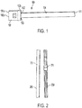
- the cable assembly 100 comprises a ribbon cable 101, comprising a plurality of optical fibers (not shown) having fiber endfaces 101a, and an elastomeric sheathing 104 being disposed over at least a portion of the ribbon cable and terminating at a sheathing end 103, short of the endfaces 101a such that the endfaces 101a protrude beyond the sheathing end 103.
- the cable assembly 100 also comprises a ferrule 102 having a mating surface 102a presenting the endfaces 101a, and a rear end 102b defining a rear opening 112 through which the optical fibers pass.
- the cable assembly 100 comprises cured adhesive disposed in the ferrule to secure the optical fibers to the ferrule.
- the elastomeric material comprises a halogen-based material, such as, for example, a fluoropolymer, such as polyvinylidene fluoride or polyvinylidene difluoride (PVDF), fluorinated ethylene propylene (FEP), perfluoroalkoxy polymer (PFA), or polytetrafluoroethylene (PTFE).
- a fluoropolymer such as polyvinylidene fluoride or polyvinylidene difluoride (PVDF), fluorinated ethylene propylene (FEP), perfluoroalkoxy polymer (PFA), or polytetrafluoroethylene (PTFE).
- the elastomeric material comprises a silicon-based rubber or other rubber.
- the elastomeric material is a heat shrink material, such as, for example, VersafitTM tubing, commercially available through Raychem, TE Conductivity.
- Versafit tubing is made from a crosslinked polyolefin to provide high flame retardance (VW-1), excellent flexibility, and a low shrink temperature (to reduce installation time).
- VW-1 high flame retardance
- Versafit tubing is free of polybrominated biphenyls (PBBs) and polybrominated biphenyl oxides and ethers (PBBOs/PBBEs). In Europe, these chemicals are classified as environmentally hazardous substances.
- the elastomeric sheathing has flexibility, abrasion resistance and flame retardance at least that of Versafit tubing as described on this webpage.
- the elastomeric material has one or more of the following properties in any combination (tested under ASTM D 2671): a Secant modulus of 1x10 4 - 2.5x10 4 psi, an ultimate elongation of 150-200%, eccentricity (recovered) of 20-40%, tensile strength of 1000 to 1500 psi, heat resistance (7 days at 158°C/316°F), Corrosive effect no corrosion (7 days at 158°C/316°F), and copper stability no brittleness, glazing, cracking, no pitting or blackening of copper, followed by test for ultimate elongation percent 90-100%.
- the elastomeric material has one or more of the following properties in any combination (tested under UL 224): low-temperature flexibility no cracking (I hour at -45°C/-49°F), heat shock no cracking UL 224 (1 hour at 136°C/277°F), Tensile strength psi 50-70%, ultimate elongation 90-100%, and flexibility no cracking. Additionally, in one embodiment, the elastomeric material has passes UL 224, VW-I flammability test.
- the sheathing may be disposed about the ribbon cable in various ways. For example, in one embodiment, discrete sections of the sheathing are slipped over the ribbon cable, and overlapping joints are formed, which are sealed, for example, through heat shrinking. In another embodiment, the ribbon cable is pulled through a long length of sheathing, which is then heat shrunk around the ribbon cable. In yet another embodiment, the sheathing is extruded around the ribbon cable in a continuous process. Still other methods for disposing the sheathing around the ribbon cable will be obvious to those of skill in the art in light of this disclosure.
- a method of preparing the cable assembly 100 is shown.
- An important aspect of this embodiment of preparing the cable assembly is that the sheathed ribbon cable of the present invention may be terminated with a ferrule using the same tools and methods as a standard ribbon cable.
- the termination of the sheathed ribbon cable with a ferrule is described herein relative to the termination of a conventional ribbon cable.
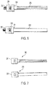
- a ribbon cable 200 sheathed by the elastomeric sheathing 201 is shown beside a conventional ribbon cable 250 and the boot 251, which, as described below, is needed in the prior art to prevent adhesive from flowing out of the ferrule during the cable assembly process.
- the boot acts as a plug.
- the cable assembly of the present invention does not require a plug.
- the conventional ribbon cable 250 shown in Fig. 2 is placed in a conventional stripping device 301, such as, for example, the Fujikura HJS-02 Hot Stripper.
- a conventional stripping device 301 such as, for example, the Fujikura HJS-02 Hot Stripper.
- Fig. 3a shows the fiber 250 being disposed in the device 301 prior to stripping.
- Fig. 3b shows the ribbon cable 250 stripped to define a stripped portion 252 at the end of the ribbon cable 250.
- the sheathed ribbon cable 200 is placed in the same device 301, which is actuated to strip a portion of the sheathed cable 200 to define a stripped portion 202.
- the coating of the ribbon cable not only was the coating of the ribbon cable removed (as was done to the conventional ribbon fiber 250 in Figs. 3a and 3b ), but also a portion of the sheathing covering the stripped portion 202 was also removed. No recalibration or alteration of device 301 was needed. This is an important benefit of the present invention--the sheathed ribbon cable of the present invention is terminated using the same techniques and tools as used in terminating a conventional ribbon cable.
- the sheathed ribbon cable 200 and the conventional ribbon cable 250 both define essentially the same stripped portions 202 and 252, respectively.
- ferrules are well known and, accordingly, they will not be described herein in detail. Suffice to say that certain ferrules are commonly used for ribbon cable, such as, for example, MT ferrules. Suitable ferrules are configured with a front face, also known as a mating face, which is adapted to mate with another optical component such as, for example, a mating face of a transceiver, transmitter, receiver, or other passive or active optical component. Ferrules also have a rear end, essentially opposite that of the mating face, which defines an opening/orifice to receive the fibers such that the fibers can pass through the ferrule to the mating face.
- ferrules define a cavity for receiving adhesive such as an epoxy or other well-known adhesive for securing fibers to the ferrule.
- adhesive such as an epoxy or other well-known adhesive for securing fibers to the ferrule.
- the ferrule comprises a window through which adhesive is injected into the ferrule such that the adhesive flows around the fibers to ensure the fibers are secured to the ferrule. This is a well-known technique and will not be discussed further herein.
- the sheathing around the ribbon cable contacts the rear end of the ferrule to form an adhesive tight seal that prevents the adhesive from flowing out of the rear opening.
- the configuration of the sheathing contacting the rear end of the ferrule may vary.
- the sheathing is received within the rear opening such that the physical contact between the sheathing and the rear opening prevents adhesive from leaking out.
- the sheathing may butt up against the rear of the ferrule to achieve physical contact sufficient to prevent adhesive from leaking out.
- the rear end may have a protrusion/nipple, which is received in the sheathing with sufficient physical contact to prevent adhesive from leaking out.
- the cable assembly the present invention does not comprise a boot.
- a significant benefit of the sheathed ribbon cable of the present invention is not only the abrasion resistance/durability that the sheathing provides, but also the simplicity in terminating a ferrule by eliminating the need for a boot.
- the adhesive is applied to the ferrules 203 and 253 to secure the fibers to the ferrules in a known and conventional way.
- a syringe is used to inject adhesive through the window in the ferrule into the body of the ferrule such that the adhesive flows around the fibers.
- the fibers are "pistoned" in the ferrule by sliding the ferrule up and down the stripped fibers. Such a motion serves to ensure that a coating of adhesive is applied around the fibers throughout the ferrule. Again, such technique is known in the art.
- the assembly is subjected to conditions to facilitate curing of the adhesive.
- conditions can vary according to the application.
- the ferrule is heated to cure the adhesive.
- the adhesive may be a UV-cured type adhesive, in which case, UV light is applied to the ferrule. Still other methods and techniques for curing adhesive will be known to those of skill in the art in light of this disclosure.
- FIG. 6 a side-by-side comparison of the ferrule of the almost completed cable assemblies 200 and 250 of the present invention and conventional art, respectively, are shown with a portion of the strip fibers extending from the mating face of the ferrule. It is important to understand that essentially no extra steps or different tools are used to terminate the ferrule on the sheathed ribbon cable of the present invention or the conventional ribbon cable. Moreover, as mentioned above, the sheathed ribbon cable of the present invention eliminates the need for a boot. Thus, the ferrule termination process is actually simplified.
- the stripped fibers are cleaved, and the mating face of the ferrule is polished.
- the protruding stripped fibers may be removed through laser cleaving or other technique which does not involve polishing. Again, such techniques are known in the art will not to be discussed herein in detail.
- the cable assembly is further encapsulated in a second sheathing such as a convoluted tubing or spiral rigid tubing such as Convalex® tubing or similar material.
- a second sheathing such as a convoluted tubing or spiral rigid tubing such as Convalex® tubing or similar material.
- Convalex tubing will be obvious of those of skill in the art in the light of this disclosure.
Landscapes
- Physics & Mathematics (AREA)
- General Physics & Mathematics (AREA)
- Optics & Photonics (AREA)
- Mechanical Coupling Of Light Guides (AREA)
Abstract
Description
- The present invention relates, generally, to optical ribbon cable, and, more specifically, to a sheathed optical ribbon cable terminated with a ferrule, which is abrasion and/or chemical/heat resistant.
- Optical ribbon cable is used commonly to connect optical components together and is a convenient solution for applications having space and weight limitations. A conventional ribbon comprises optical fibers, which are placed side-by-side and encapsulated with a coating or a tape, for example, Mylar, to form a strip of optical fibers. A single ribbon may contain, for example, 4, 8, 12, or more optical fibers.
- The advantage of utilizing ribbon fiber cables resides in the ability to achieve a much higher density in a patch panel, cable routing/ducting, and device connection environments, without compromising the quality or quantity of the connection. Because the ribbon contains only coated optical fibers, this type of cable takes up much less space than individually buffered optical fibers. As a result, ribbon cables are denser than any other cable design. They are ideal for applications where limited space is available, such as in an existing conduit that has very little room left for an additional cable.
- Although ribbon cable is a good solution for high density optical applications, the absence of a buffer makes them susceptibility to abrasion, which necessitates taking certain precautions that complicate the assembly/installation process. Specifically, ribbon cable cannot rub against other objects, and, thus, in environments involving vibration, the cable must be secured with tiedowns and other mechanical means to prevent it from rubbing against other objects. The need for such tiedowns not only introduces additional steps/expense in the installation process, but also often presents challenges because a purchase point for a tiedown is not often available. Accordingly, the applicant has identified the need for an abrasion resistant ribbon cable that minimizes the need for tiedowns and other mechanical restraints. Furthermore, as the use of ribbon cables becomes more prevalent in rugged and demanding applications, such as aerospace, the applicant has also identified the need for a ribbon cable that is chemically and thermally resistant. The present invention fulfills these needs, among others.
- The solution is provided by a cable assembly comprising: (a) a ribbon cable having a plurality of optical fibers having endfaces; (b) an elastomeric sheathing being disposed over at least a portion of the ribbon cable and terminating in a sheathing end near the endfaces such that the endfaces protrude beyond the sheathing end; (c) a ferrule having an mating surface presenting the endfaces, and a rear end having a rear opening through which the optical fibers pass, the rear end contacting the sheathing end to form an adhesive tight seal sufficient to prevent liquid adhesive in the ferrule from flowing out of the rear opening; and (d) adhesive disposed in the ferrule to secure the optical fibers to the ferrule.
- Furthermore, the invention also provides a method of preparing a cable assembly comprising: (a) disposing the elastomeric sheathing over a ribbon cable having a plurality of optical fibers; (b) stripping the optical fibers and the sheathing to form stripped optical fibers that protrude beyond an end of the sheathing; (c) inserting the stripped optical fibers through a rear opening at a rear of a ferrule such that (i) endfaces of the stripped optical fibers protrude beyond a mating face of the ferrule, and (ii) the end of the sheathing contacts the rear to form an adhesive-tight seal between the ferrule and the sheathing; (d) disposing liquid adhesive in the ferrule; and (e) causing the liquid adhesive to cure.
-
Fig. 1 shows one embodiment of the ribbon cable assembly of the present invention. -
Fig. 2 shows a side-by-side comparison of the sheathed ribbon cable of the present invention (prior to termination of a ferrule) compared to conventional ribbon cable having a boot (also prior to termination of a ferrule). -
Figs. 3a - 3d show various steps of the process of stripping a conventional ribbon cable and stripping the sheathed ribbon cable of the present invention for termination of a ferrule. -
Fig. 4 shows a side-by-side comparison of the stripped sheathed ribbon cable of the present invention and a stripped conventional ribbon cable. -
Figs. 5a - 5b show a side-by-side comparison of applying adhesive to a ferrule attached to the sheathed ribbon cable the present invention and to a ferrule attached to a conventional ribbon cable. -
Fig. 6 shows a side-by-side comparison of the almost complete cable assemblies of a conventional ribbon cable terminated with a ferrule and the sheathed ribbon cable of the present invention terminated with a ferrule, with stripped fibers protruding from the mating face of each ferrule. -
Fig. 7 shows a side-by-side comparison of the completed cable assembly of a traditional ferrule terminated ribbon cable and a ferrule terminated sheathed ribbon cable of the present invention. - The invention will now be described by way of example with reference to the accompanying drawings in which:
- Referring to
Fig. 1 , one embodiment of thecable assembly 100 of the present invention is shown. In this embodiment, thecable assembly 100 comprises aribbon cable 101, comprising a plurality of optical fibers (not shown) havingfiber endfaces 101a, and anelastomeric sheathing 104 being disposed over at least a portion of the ribbon cable and terminating at a sheathingend 103, short of theendfaces 101a such that theendfaces 101a protrude beyond the sheathingend 103. Thecable assembly 100 also comprises aferrule 102 having amating surface 102a presenting theendfaces 101a, and arear end 102b defining arear opening 112 through which the optical fibers pass. Therear end 102b contacts the sheathingend 103 to form a liquid adhesive tight seal sufficient to prevent liquid adhesive in the ferrule from flowing out of the rear end. In its final form, thecable assembly 100 comprises cured adhesive disposed in the ferrule to secure the optical fibers to the ferrule. - An important aspect of the claimed invention is the elastomeric sheathing surrounding the ribbon cable to provide abrasion and/or chemical and/or heat resistance. Suitable elastomeric materials will be obvious to those of skill in the art in light of this disclosure. In one embodiment, the elastomeric material comprises a halogen-based material, such as, for example, a fluoropolymer, such as polyvinylidene fluoride or polyvinylidene difluoride (PVDF), fluorinated ethylene propylene (FEP), perfluoroalkoxy polymer (PFA), or polytetrafluoroethylene (PTFE). In another embodiment, the elastomeric material comprises a silicon-based rubber or other rubber. In one embodiment, the elastomeric material is a heat shrink material, such as, for example, Versafit™ tubing, commercially available through Raychem, TE Conductivity. Versafit tubing is made from a crosslinked polyolefin to provide high flame retardance (VW-1), excellent flexibility, and a low shrink temperature (to reduce installation time). Unlike other typical flame-retardant tubing, Versafit tubing is free of polybrominated biphenyls (PBBs) and polybrominated biphenyl oxides and ethers (PBBOs/PBBEs). In Europe, these chemicals are classified as environmentally hazardous substances. See for example: https://www.te.com/commerce/DocumentDelivery/DDEController?Action-showdoc&DocId= Data+Sheet%7FVERSAFIT%7F404%7Fpdf%7FEnglish%7FENG DS_VERSAFIT_404.pdf %7F5562734018, hereby incorporated by reference. In one embodiment, the elastomeric sheathing has flexibility, abrasion resistance and flame retardance at least that of Versafit tubing as described on this webpage.
- In one embodiment, the elastomeric material has one or more of the following properties in any combination (tested under ASTM D 2671): a Secant modulus of 1x10⁴ - 2.5x10⁴ psi, an ultimate elongation of 150-200%, eccentricity (recovered) of 20-40%, tensile strength of 1000 to 1500 psi, heat resistance (7 days at 158°C/316°F), Corrosive effect no corrosion (7 days at 158°C/316°F), and copper stability no brittleness, glazing, cracking, no pitting or blackening of copper, followed by test for ultimate elongation percent 90-100%. Additionally, in one embodiment, the elastomeric material has one or more of the following properties in any combination (tested under UL 224): low-temperature flexibility no cracking (I hour at -45°C/-49°F), heat shock no cracking UL 224 (1 hour at 136°C/277°F), Tensile strength psi 50-70%, ultimate elongation 90-100%, and flexibility no cracking. Additionally, in one embodiment, the elastomeric material has passes UL 224, VW-I flammability test.
- The sheathing may be disposed about the ribbon cable in various ways. For example, in one embodiment, discrete sections of the sheathing are slipped over the ribbon cable, and overlapping joints are formed, which are sealed, for example, through heat shrinking. In another embodiment, the ribbon cable is pulled through a long length of sheathing, which is then heat shrunk around the ribbon cable. In yet another embodiment, the sheathing is extruded around the ribbon cable in a continuous process. Still other methods for disposing the sheathing around the ribbon cable will be obvious to those of skill in the art in light of this disclosure.
- Referring to
Figs. 2 through 7 , one embodiment of a method of preparing thecable assembly 100 is shown. An important aspect of this embodiment of preparing the cable assembly is that the sheathed ribbon cable of the present invention may be terminated with a ferrule using the same tools and methods as a standard ribbon cable. In this respect, the termination of the sheathed ribbon cable with a ferrule is described herein relative to the termination of a conventional ribbon cable. - Referring to
Fig. 2 , aribbon cable 200 sheathed by theelastomeric sheathing 201 is shown beside aconventional ribbon cable 250 and theboot 251, which, as described below, is needed in the prior art to prevent adhesive from flowing out of the ferrule during the cable assembly process. In other words, the boot acts as a plug. The cable assembly of the present invention does not require a plug. - Referring to
Figs. 3a and 3b , theconventional ribbon cable 250 shown inFig. 2 is placed in aconventional stripping device 301, such as, for example, the Fujikura HJS-02 Hot Stripper. Such devices are well-known and commercially available.Fig. 3a shows thefiber 250 being disposed in thedevice 301 prior to stripping.Fig. 3b shows theribbon cable 250 stripped to define a strippedportion 252 at the end of theribbon cable 250. - Similarly, in
Figs. 3c and 3d , thesheathed ribbon cable 200 is placed in thesame device 301, which is actuated to strip a portion of thesheathed cable 200 to define a strippedportion 202. It should be noted that, during the stripping operation, not only was the coating of the ribbon cable removed (as was done to theconventional ribbon fiber 250 inFigs. 3a and 3b ), but also a portion of the sheathing covering the strippedportion 202 was also removed. No recalibration or alteration ofdevice 301 was needed. This is an important benefit of the present invention--the sheathed ribbon cable of the present invention is terminated using the same techniques and tools as used in terminating a conventional ribbon cable. - Thus, as shown in
Fig. 4 , at the end of the identical stripping operation, the sheathedribbon cable 200 and theconventional ribbon cable 250 both define essentially the same strippedportions - Next, the stripped portion of the optical fibers are inserted through a conventional ferrule. Ferrules are well known and, accordingly, they will not be described herein in detail. Suffice to say that certain ferrules are commonly used for ribbon cable, such as, for example, MT ferrules. Suitable ferrules are configured with a front face, also known as a mating face, which is adapted to mate with another optical component such as, for example, a mating face of a transceiver, transmitter, receiver, or other passive or active optical component. Ferrules also have a rear end, essentially opposite that of the mating face, which defines an opening/orifice to receive the fibers such that the fibers can pass through the ferrule to the mating face. Additionally, most ferrules define a cavity for receiving adhesive such as an epoxy or other well-known adhesive for securing fibers to the ferrule. In one embodiment, as described below, the ferrule comprises a window through which adhesive is injected into the ferrule such that the adhesive flows around the fibers to ensure the fibers are secured to the ferrule. This is a well-known technique and will not be discussed further herein.
- An important aspect of the invention is that the sheathing around the ribbon cable contacts the rear end of the ferrule to form an adhesive tight seal that prevents the adhesive from flowing out of the rear opening. The configuration of the sheathing contacting the rear end of the ferrule may vary. In one embodiment, the sheathing is received within the rear opening such that the physical contact between the sheathing and the rear opening prevents adhesive from leaking out. Alternatively, the sheathing may butt up against the rear of the ferrule to achieve physical contact sufficient to prevent adhesive from leaking out. In still another embodiment, the rear end may have a protrusion/nipple, which is received in the sheathing with sufficient physical contact to prevent adhesive from leaking out. Still other embodiments will be obvious to those of skill in the art in light of this disclosure. Conversely, in the prior art, a
boot 251 is necessary to essentially plug the rear opening of the ferrule to prevent adhesive from leaking out. Thus, in one embodiment, the cable assembly the present invention does not comprise a boot. Thus, a significant benefit of the sheathed ribbon cable of the present invention is not only the abrasion resistance/durability that the sheathing provides, but also the simplicity in terminating a ferrule by eliminating the need for a boot. - Next, as shown in
Figs. 5 a and 5B, the adhesive is applied to theferrules - Once the liquid adhesive is applied to the ferrule, the assembly is subjected to conditions to facilitate curing of the adhesive. Such conditions can vary according to the application. For example, in one embodiment, the ferrule is heated to cure the adhesive. Alternatively, the adhesive may be a UV-cured type adhesive, in which case, UV light is applied to the ferrule. Still other methods and techniques for curing adhesive will be known to those of skill in the art in light of this disclosure.
- Referring to
Fig. 6 , a side-by-side comparison of the ferrule of the almost completedcable assemblies - Next, a portion of the stripped fiber extending from the mating faces 255 and 205 of the ferrules is removed to form completed
cable assemblies - In one embodiment, the cable assembly is further encapsulated in a second sheathing such as a convoluted tubing or spiral rigid tubing such as Convalex® tubing or similar material. The applications of Convalex tubing will be obvious of those of skill in the art in the light of this disclosure.
Claims (15)
- A cable assembly (100) comprising:a ribbon cable (101) comprising a plurality of optical fibers having endfaces (101a);an elastomeric sheathing (104) being disposed over at least a portion of said ribbon cable (101) and terminating at a sheathing end (103) short of said endfaces (101a) such that said endfaces (101a) protrude beyond said sheathing end (103);a ferrule (102) having a mating surface (102a) presenting said endfaces (101a), and a rear end (102b) having a rear opening (112) through which said optical fibers pass, said rear end (102b) contacting said sheathing end (103) to form an adhesive-tight seal sufficient to prevent liquid adhesive in said ferrule (102) from flowing out of said rear opening (112); andcured adhesive disposed in said ferrule (102) to secure said optical fibers to said ferrule (102).
- The cable assembly (100) of claim 1, wherein said cable assembly (100) does not have a boot.
- The cable assembly (100) of claim 1 or 2, wherein said elastomeric sheathing (104) is a halogen-based material.
- The cable assembly (100) of any preceding claim, wherein said elastomeric sheathing (104) is a fluoropolymer material.
- The cable assembly (100) of any preceding claim, wherein said is elastomeric sheathing (104) is one of polyvinylidene fluoride or polyvinylidene difluoride (PVDF), fluorinated ethylene propylene (FEP), perfluoroalkoxy polymer (PFA), or polytetrafluoroethylene (PTFE).
- The cable assembly (100) of claim 1 or 2, wherein said elastomeric sheathing (104) is a silicone-based rubber material.
- The cable assembly (100) of any preceding claim, wherein the elastomeric sheathing (104) is a heat shrink material.
- The cable assembly (100) of any preceding claim, wherein said elastomeric sheathing (104) is extruded over said ribbon cable (101).
- The cable assembly (100) of any preceding claim, wherein said ferrule (102) is an MT ferrule
- The cable assembly (100) of any preceding claim, further comprising a convoluted tubing around said elastomeric sheathing (104).
- A method of preparing a cable assembly (100), said method comprising
disposing elastomeric sheathing (104) over a ribbon cable (101) having a plurality of optical fibers;
stripping said optical fibers and said sheathing (104) to form stripped optical fibers (202) that protrude beyond an end (103) of said sheathing (104);
inserting said stripped optical fibers (202) through a rear opening (112) at a rear (102b) of a ferrule (102) such that (a) endfaces (101a) of said stripped optical fibers (202) protrude beyond a mating face (102a) of said ferrule (102), and (b) said end (103) of said sheathing (104) contacts said rear (102b) of said ferrule (102) to form an adhesive-tight seal between said ferrule (102) and said sheathing (104);
disposing liquid adhesive in said ferrule (102); and
causing said liquid adhesive to cure. - The method of claim 11, wherein disposing said sheathing (104) around said ribbon cable (101) comprises heat shrinking said sheathing (104) around said ribbon cable (101).
- The method of claim 11 or 12, wherein disposing said sheathing (104) around said ribbon cable (101) comprises slipping sections of said sheathing (104) over the ribbon cable (101) to form overlapping joints between said sections, and then sealing said overlapping joints.
- The method of claim 11, 12 or 13 wherein disposing said sheathing (104) around said ribbon cable (101) comprises pulling a length of said sheathing (104) over the ribbon cable (101).
- The method of claim 11, wherein disposing said sheathing (104) around said ribbon cable (101) comprises extruding said sheathing (104) around said ribbon cable (101).
Applications Claiming Priority (1)
| Application Number | Priority Date | Filing Date | Title |
|---|---|---|---|
| US16/249,810 US10969551B2 (en) | 2019-01-16 | 2019-01-16 | Sheathed optical ribbon cable assembly |
Publications (2)
| Publication Number | Publication Date |
|---|---|
| EP3683609A1 true EP3683609A1 (en) | 2020-07-22 |
| EP3683609B1 EP3683609B1 (en) | 2026-05-13 |
Family
ID=69182469
Family Applications (1)
| Application Number | Title | Priority Date | Filing Date |
|---|---|---|---|
| EP20152117.6A Active EP3683609B1 (en) | 2019-01-16 | 2020-01-16 | Sheathed optical ribbon cable assembly |
Country Status (3)
| Country | Link |
|---|---|
| US (1) | US10969551B2 (en) |
| EP (1) | EP3683609B1 (en) |
| CA (1) | CA3068221A1 (en) |
Families Citing this family (2)
| Publication number | Priority date | Publication date | Assignee | Title |
|---|---|---|---|---|
| US11927823B2 (en) * | 2021-02-26 | 2024-03-12 | Te Connectivity Solutions Gmbh | Cable assembly |
| JP7737887B2 (en) * | 2021-12-17 | 2025-09-11 | 株式会社白山 | Ferrule, optical connector, and method of manufacturing the optical connector |
Citations (5)
| Publication number | Priority date | Publication date | Assignee | Title |
|---|---|---|---|---|
| US4261643A (en) * | 1979-02-05 | 1981-04-14 | Sea-Log Corporation | Method and apparatus for joining the ends of two fiber optic cables |
| JPH0743560A (en) * | 1992-03-30 | 1995-02-14 | Ngk Insulators Ltd | Fixed structure for multi-core optical fiber |
| US20030152350A1 (en) * | 1999-09-21 | 2003-08-14 | The Furukawa Electric Co., Ltd | Optical fiber unit |
| US20090154884A1 (en) * | 2005-04-04 | 2009-06-18 | Wenzong Chen | Multifiber MT-Type Connector and Ferrule Comprising V-Groove Lens Array and Method of Manufacture |
| US20090251697A1 (en) * | 2007-12-17 | 2009-10-08 | Serge Cutillas | Laser emitter modules and methods of assembly |
Family Cites Families (11)
| Publication number | Priority date | Publication date | Assignee | Title |
|---|---|---|---|---|
| JP2699242B2 (en) * | 1992-05-26 | 1998-01-19 | 株式会社フジクラ | Optical fiber connector |
| US5764835A (en) * | 1996-05-07 | 1998-06-09 | W. L. Gore & Associates, Inc. | Fluoropolymer fiber reinforced integral composite cable jacket and tubing |
| US5815621A (en) * | 1996-05-23 | 1998-09-29 | Sumitomo Electric Industries, Ltd. | Optical fiber connector ferrule with die and method of manufacturing same |
| US6062740A (en) * | 1997-08-25 | 2000-05-16 | Sumitomo Electric Industries, Ltd. | Optical connector and method of making the same |
| US6565265B2 (en) * | 2000-03-23 | 2003-05-20 | Sumitomo Electric Industries, Ltd. | Optical connector and method of assembling optical connector |
| US20030202766A1 (en) * | 2002-04-29 | 2003-10-30 | Lynx Photonic Networks Inc. | Sealed package for optical component |
| US7314317B2 (en) * | 2004-03-25 | 2008-01-01 | Kabushiki Kaisha Toshiba | Optical fiber connector and connecting method |
| US7289704B1 (en) * | 2006-10-31 | 2007-10-30 | Corning Cable Systems Llc | Fiber optic cables that kink with small bend radii |
| US7364375B1 (en) * | 2006-12-18 | 2008-04-29 | Lockheed Martin Corporation | Method and apparatus for splicing a fiber optic cable |
| JP5736490B1 (en) * | 2014-05-29 | 2015-06-17 | 株式会社フジクラ | Optical fiber unit with connector, optical connector boot |
| WO2016200860A1 (en) * | 2015-06-09 | 2016-12-15 | Commscope Technologies Llc | Device for transitioning from trunk cable to jumper cable |
-
2019
- 2019-01-16 US US16/249,810 patent/US10969551B2/en active Active
-
2020
- 2020-01-16 EP EP20152117.6A patent/EP3683609B1/en active Active
- 2020-01-16 CA CA3068221A patent/CA3068221A1/en active Pending
Patent Citations (5)
| Publication number | Priority date | Publication date | Assignee | Title |
|---|---|---|---|---|
| US4261643A (en) * | 1979-02-05 | 1981-04-14 | Sea-Log Corporation | Method and apparatus for joining the ends of two fiber optic cables |
| JPH0743560A (en) * | 1992-03-30 | 1995-02-14 | Ngk Insulators Ltd | Fixed structure for multi-core optical fiber |
| US20030152350A1 (en) * | 1999-09-21 | 2003-08-14 | The Furukawa Electric Co., Ltd | Optical fiber unit |
| US20090154884A1 (en) * | 2005-04-04 | 2009-06-18 | Wenzong Chen | Multifiber MT-Type Connector and Ferrule Comprising V-Groove Lens Array and Method of Manufacture |
| US20090251697A1 (en) * | 2007-12-17 | 2009-10-08 | Serge Cutillas | Laser emitter modules and methods of assembly |
Also Published As
| Publication number | Publication date |
|---|---|
| EP3683609B1 (en) | 2026-05-13 |
| US10969551B2 (en) | 2021-04-06 |
| US20200225431A1 (en) | 2020-07-16 |
| CA3068221A1 (en) | 2020-07-16 |
Similar Documents
| Publication | Publication Date | Title |
|---|---|---|
| US8050527B2 (en) | Self healing optical fiber cable assembly and method of making the same | |
| US10036859B2 (en) | Cable termination assembly and method for connectors | |
| US8132969B2 (en) | Fiber optic connector assembly and method for venting gas inside a fiber optic connector sub-assembly | |
| US8885998B2 (en) | Splice enclosure arrangement for fiber optic cables | |
| US6295401B1 (en) | Optical fiber ribbon cables | |
| US6438299B1 (en) | Assembly and method for furcating optical fibers | |
| CA2987357C (en) | Optical fiber cord and method of manufacturing optical fiber cord | |
| US7410308B2 (en) | Fiber optic cable splice | |
| US9239435B2 (en) | Optical fiber cable having connector and assembling method thereof | |
| WO2018146470A4 (en) | Pre-terminated optical fibre cable assembly, methods of manufacture and installation thereof | |
| CN103345019A (en) | Optical fiber connector and optical fiber assembly method | |
| US7494289B1 (en) | Optical fibre splice protector | |
| US20080138026A1 (en) | Furcation tubing and fanout furcation kit | |
| EP3683609B1 (en) | Sheathed optical ribbon cable assembly | |
| US7187829B2 (en) | Low smoke, low toxicity fiber optic cable | |
| US20200400897A1 (en) | Fiber optic connector assembly with crimp tube subassembly and method of use | |
| CN103718075B (en) | Cable assembly including the connector with stable fiber length in it | |
| US20220137296A1 (en) | Multi-fiber splice protector and cable assembly with intra-connector splices, and fabrication method | |
| US7192194B2 (en) | Universal adapter for fiber optic connectors | |
| US11886009B2 (en) | Coating fusion spliced optical fibers and subsequent processing methods thereof | |
| US12019281B2 (en) | Sealed optical cable assemblies and methods of fabricating the same | |
| GB2140930A (en) | Protected fibre optic cable and coupler therefor | |
| US20230221515A1 (en) | Optical fiber cable with embedded strength members | |
| CN213659033U (en) | Optical cable suitable for leading-in cable application | |
| CA2639818C (en) | Optical fiber cables |
Legal Events
| Date | Code | Title | Description |
|---|---|---|---|
| PUAI | Public reference made under article 153(3) epc to a published international application that has entered the european phase |
Free format text: ORIGINAL CODE: 0009012 |
|
| STAA | Information on the status of an ep patent application or granted ep patent |
Free format text: STATUS: THE APPLICATION HAS BEEN PUBLISHED |
|
| AK | Designated contracting states |
Kind code of ref document: A1 Designated state(s): AL AT BE BG CH CY CZ DE DK EE ES FI FR GB GR HR HU IE IS IT LI LT LU LV MC MK MT NL NO PL PT RO RS SE SI SK SM TR |
|
| AX | Request for extension of the european patent |
Extension state: BA ME |
|
| STAA | Information on the status of an ep patent application or granted ep patent |
Free format text: STATUS: REQUEST FOR EXAMINATION WAS MADE |
|
| 17P | Request for examination filed |
Effective date: 20210115 |
|
| RBV | Designated contracting states (corrected) |
Designated state(s): AL AT BE BG CH CY CZ DE DK EE ES FI FR GB GR HR HU IE IS IT LI LT LU LV MC MK MT NL NO PL PT RO RS SE SI SK SM TR |
|
| STAA | Information on the status of an ep patent application or granted ep patent |
Free format text: STATUS: EXAMINATION IS IN PROGRESS |
|
| 17Q | First examination report despatched |
Effective date: 20220131 |
|
| RAP1 | Party data changed (applicant data changed or rights of an application transferred) |
Owner name: TYCO ELECTRONICS UK LTD Owner name: TE CONNECTIVITY SOLUTIONS GMBH |
|
| GRAP | Despatch of communication of intention to grant a patent |
Free format text: ORIGINAL CODE: EPIDOSNIGR1 |
|
| STAA | Information on the status of an ep patent application or granted ep patent |
Free format text: STATUS: GRANT OF PATENT IS INTENDED |
|
| INTG | Intention to grant announced |
Effective date: 20260113 |
|
| GRAS | Grant fee paid |
Free format text: ORIGINAL CODE: EPIDOSNIGR3 |
|
| GRAA | (expected) grant |
Free format text: ORIGINAL CODE: 0009210 |
|
| STAA | Information on the status of an ep patent application or granted ep patent |
Free format text: STATUS: THE PATENT HAS BEEN GRANTED |
|
| AK | Designated contracting states |
Kind code of ref document: B1 Designated state(s): AL AT BE BG CH CY CZ DE DK EE ES FI FR GB GR HR HU IE IS IT LI LT LU LV MC MK MT NL NO PL PT RO RS SE SI SK SM TR |
|
| REG | Reference to a national code |
Ref country code: CH Ref legal event code: F10 Free format text: ST27 STATUS EVENT CODE: U-0-0-F10-F00 (AS PROVIDED BY THE NATIONAL OFFICE) Effective date: 20260513 |