EP3683587A1 - Power supply control circuits for brushless dc (bldc) motors - Google Patents
Power supply control circuits for brushless dc (bldc) motors Download PDFInfo
- Publication number
- EP3683587A1 EP3683587A1 EP19382023.0A EP19382023A EP3683587A1 EP 3683587 A1 EP3683587 A1 EP 3683587A1 EP 19382023 A EP19382023 A EP 19382023A EP 3683587 A1 EP3683587 A1 EP 3683587A1
- Authority
- EP
- European Patent Office
- Prior art keywords
- shunt
- bldc
- voltage
- control circuit
- total
- Prior art date
- Legal status (The legal status is an assumption and is not a legal conclusion. Google has not performed a legal analysis and makes no representation as to the accuracy of the status listed.)
- Withdrawn
Links
Images



Classifications
-
- G—PHYSICS
- G01—MEASURING; TESTING
- G01R—MEASURING ELECTRIC VARIABLES; MEASURING MAGNETIC VARIABLES
- G01R19/00—Arrangements for measuring currents or voltages or for indicating presence or sign thereof
- G01R19/0092—Measuring current only
-
- H—ELECTRICITY
- H02—GENERATION; CONVERSION OR DISTRIBUTION OF ELECTRIC POWER
- H02P—CONTROL OR REGULATION OF ELECTRIC MOTORS, ELECTRIC GENERATORS OR DYNAMO-ELECTRIC CONVERTERS; CONTROLLING TRANSFORMERS, REACTORS OR CHOKE COILS
- H02P6/00—Arrangements for controlling synchronous motors or other dynamo-electric motors using electronic commutation dependent on the rotor position; Electronic commutators therefor
- H02P6/14—Electronic commutators
-
- G—PHYSICS
- G01—MEASURING; TESTING
- G01R—MEASURING ELECTRIC VARIABLES; MEASURING MAGNETIC VARIABLES
- G01R19/00—Arrangements for measuring currents or voltages or for indicating presence or sign thereof
- G01R19/25—Arrangements for measuring currents or voltages or for indicating presence or sign thereof using digital measurement techniques
- G01R19/2513—Arrangements for monitoring electric power systems, e.g. power lines or loads; Logging
-
- H—ELECTRICITY
- H02—GENERATION; CONVERSION OR DISTRIBUTION OF ELECTRIC POWER
- H02P—CONTROL OR REGULATION OF ELECTRIC MOTORS, ELECTRIC GENERATORS OR DYNAMO-ELECTRIC CONVERTERS; CONTROLLING TRANSFORMERS, REACTORS OR CHOKE COILS
- H02P27/00—Arrangements or methods for the control of AC motors characterised by the kind of supply voltage
- H02P27/04—Arrangements or methods for the control of AC motors characterised by the kind of supply voltage using variable-frequency supply voltage, e.g. inverter or converter supply voltage
- H02P27/06—Arrangements or methods for the control of AC motors characterised by the kind of supply voltage using variable-frequency supply voltage, e.g. inverter or converter supply voltage using DC to AC converters or inverters
Definitions
- the present invention refers to power supply control circuits for BLDC motors having means to calculate a DC current consumption of the BLDC motor based on the processing of a phase current signal of the BLDC motor.
- the BLDC motor is becoming increasingly popular in sectors such as automotive (particularly electric vehicles (EV)), heating, ventilation, and air conditioning (HVAC), in white goods and industrial goods because it does away with the mechanical brush used in traditional motors. This characteristic makes the BLDC motors more reliable and increases its service life.
- EV electric vehicles
- HVAC heating, ventilation, and air conditioning
- BLDC motor Another advantage of a BLDC motor is that it can be made smaller and lighter than a brush type motor with the same power output, making the BLDC motors suitable for applications where space is tight.
- the microcontroller of the control circuit of the BLDC motor may be configured to energize the stator coils of the BLDC at the correct moment by implementing a control algorithm. Precise timing allows for accurate speed and torque control, as well as ensuring the BLDC motor runs at peak efficiency.
- the microcontroller may receive system current values as inputs and signals from position sensors (as e.g. hall sensors that indicate the position of the motor rotor) to implement the control algorithm.
- Precise motor control performed by the control circuit of the BLDC represents a very significant condition for the correct performance of the BLDC motor. Whether for electronic power steering, electronic stability control, automatic braking systems, or for the self-driving vehicle, precise motor control may be required to ensure safe and efficient operation. Hence, currents can be measured to collect information primarily on the motor torque as the current measurements can be directly proportional to the motor torque.
- Current measurements may be used to detect when an overcurrent condition occurs allowing the system to take action to prevent a potential damage in the BLDC motor.
- Current brushless DC motor control circuits may include 1 to 3 shunt resistors to measure the phase current that can be used as input for the control algorithm implemented by the microcontroller. Some algorithms may require the measurement of the DC current consumption I S .
- an additional shunt (101, 102) can be included either in the positive battery input (A) or in the battery return (B) (i.e. in the DC link) as shown in figure 1 that represents a conventional power supply control circuit (100) of a BLDC motor.
- the type of shunt resistors (101, 102) imply additional unwanted power consumption and heat dissipation in the system.
- the power supply control circuit (100) of figure 1 can comprise a DC source (105), an input AC filter (103), in particular a LC filter, a microcontroller/PWM block (110) that represents a pulse width modulation (PWM) generator that generates a PWM signal to a three-phase inverter (120) and a microcontroller implementing a control algorithm that controls the input current in the brushless DC motor (130).
- the three-phase inverter (120) comprises six switches for high-power switching to feed current to the DC motor (130).
- the output from the block (110) comprises pulse width modulated (PWM) signals that determine the average voltage and average current applied to the three coils of the BLDC motor having a "Y" formation as shown in figure 1 in order to control motor speed and motor torque.
- PWM pulse width modulated
- the BLDC motor (130) may use three hall-effect sensors not shown in the figure to indicate rotor position.
- the rotor itself uses several pairs of permanent magnets to generate the magnetic flux.
- a power supply control circuit for a BLDC that uses a procedure for measuring the input DC current consumption I S for the control algorithm other than using shunt resistors in the DC link and thus avoids additional power consumption and heat dissipation and maximizes the performance of the motor-control system is desired.
- the present invention proposes BLDC power supply control circuit that can measure the DC current consumption of the motor I S without the requirement of establishing shunt resistors (101, 102) in the DC link of the power supply in contrast to current implementations.
- shunt resistor (101) the addition of complex circuitry to measure a differential voltage value can also be avoided.
- getting rid of the shunt resistors (101, 102) may permit to ease the routing of conductive traces on a PCB supporting the control circuit.
- a power supply control circuit for a three-phase brushless DC (BLDC) comprising means for calculating a DC current consumption I S based on a phase current signal I shunt of the BLDC motor.
- the calculated DC current consumption I S may be used by a control algorithm for controlling the BLDC motor control or reported to a master controller for performing additional actions as e.g. overcurrent protection.
- the means for calculating a DC current consumption I S in the power supply control circuit comprises a shunt resistor R shunt for phase current sensing having a voltage V shunt that corresponds to a total phase current signal I shunt of the three phase BLDC motor across the shunt resistor R shunt .
- the shunt resistor R shunt can be used to perform low-side phase current sensing as shown in figures 2 and 3 .
- low-side phase sensing allows for easier determination of the motor phase currents, but it is not an exact equivalent, an error is potentially introduced relative to the true phase current.
- Low-side phase sensing also introduces a ground variation of the motor relative to system ground.
- the means for calculating a DC current consumption I S in the power supply control circuit comprises an amplifier to amplify the input voltage V shunt and perform an offset correction of the input voltage V shunt .
- the power supply control circuit also comprises a low pass filter to filter the amplified voltage signal V shunt to obtain a filtered output voltage V O .
- the filtered output voltage V O may be fed into an analogue to digital converter (ADC) (which may or may not be included into the microcontroller itself) to calculate the input DC current consumption I S from the voltage V O . value.
- ADC analogue to digital converter
- Gain is the amplification factor of the amplifier to amplify the input voltage V shunt .
- a power supply control circuit for a BLDC comprising means for calculating a DC current consumption I S according to the present disclosure.
- the power supply control circuit uses means for performing phase current sensing.
- the means comprises three shunt resistors, e.g. R Sh1 , R Sh2 and R Sh3 .
- the means of the power supply control circuit also comprises means for shunt signal amplification and offset correction, means for summation of the three shunt signals and low-pass signal filter.
- an alternative BLDC motor power supply control circuit comprising means for calculating the DC current consumption I S based on three phase current signals I Sh 1 I Sh 2 and I Sh 3 of the BLDC motor.
- the means of the power supply control circuit comprises three shunt resistors R Sh1 R Sh2 and R Sh 3 for the three phases of the BLDC motor. Furthermore, the means of the power supply control circuit comprises three amplifiers to amplify three measured voltage signals V Sh 1 , V Sh 2 and V Sh 3 corresponding to the phase current signals I Sh 1 , I Sh 2 and I Sh 3 of the BLDC motor across the shunt resistors R Sh1 R Sh2 and R Sh3 , respectively and perform an offset correction of the voltages V Sh 1 V Sh 2 and V Sh 3 .
- the Gain Total represents the total amplification factor of the three amplifiers to amplify three measured voltage signals V Sh 1 , V Sh 2 and V Sh 3 .
- the power supply control circuit comprises an AC filter comprising a capacitor and an inductance as shown in the figures.
- a method for calculating a DC current consumption I S of a three phase brushless DC (BLDC) motor the method performed by the motor microcontroller of the power supply control circuit.
- the method comprises a step for amplifying a voltage signal V shunt corresponding to a total phase current signal I shunt of the BLDC motor across a shunt resistor R shunt .
- the shunt resistor R shunt can measure low-side phase current.
- the method comprises a step for performing an offset correction of the voltage signal V shunt .
- the method further comprises a step for obtaining an output voltage V O by low-pass filtering the amplified voltage signal V shunt .
- the method comprises a step for obtaining the DC current consumption I S based on the output voltage V O and according to equation 1.
- the motor microcontroller can be configured to implement a control algorithm for controlling the BLDC motor based at least on the calculated I S .
- a master controller may use the calculated I S for performing e.g. overcurrent protection.
- a second method for calculating a DC current consumption I S of a three phase brushless DC (BLDC) motor the method is also performed by the motor microcontroller of the power supply control circuit.
- the method comprises a step for amplifying three voltage signals V Sh 1 V Sh 2 and V Sh 3 corresponding to three phase current signals I Sh 1 I Sh 2 I Sh 3 of the BLDC motor across shunt resistors R Sh1 , R Sh 2 and R Sh 3 , respectively.
- the shunt resistors can measure low-side phase currents.
- the method comprises a step for performing offset correction of the three voltage signals V Sh 1 V Sh 2 and V Sh 3 .
- the method comprises obtaining a total tension V ShT by summing the three voltage signals V Sh 1 V Sh 2 and V Sh 3 and obtaining a filtered voltage V O by low-pass filtering the total tension V ShT . Finally the DC current consumption I S is obtained based on the output voltage V O and according to the equation 2.
- FIG. 2 shows a power supply control circuit (200) for a BLDC (130) having a "Y" formation.
- the BLDC (130) can have a "Delta” formation.
- the advantages of the configuration of the power supply control circuit (200) are cost reduction, the PCB area for placement of the control circuit is smaller compared to other configurations. Furthermore, one single ADC converters is needed.
- the control circuit (200) comprises a microcontroller/PWM control block (210) that generates a PWM signal for a power inverter (120) which produces an AC electric current that feeds the BLDC motor (130).
- the microcontroller/PWM block (210) controls current in the brushless DC motor (130) based on a control algorithm implemented by the microcontroller.
- the control circuit (200) comprises means for calculating a DC current consumption I S based on a phase current signal I shunt of the BLDC motor, the means comprises a R shunt (215) for measuring low-side current sensing and an input AC filter (103).
- the voltage V shunt corresponding to the current I Shunt across R shunt (215) is measured, amplified, offset corrected and filtered as shown in figure 4 .
- the DC current consumption I S is calculated according to equation 1.
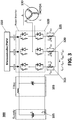
- FIG. 3 shows a power supply control circuit (300) for the BLDC (130).
- the advantages of the configuration of the power supply control circuit (300) are that this configuration can obtain more precise phase currents readings and involve less acoustic noise and less total harmonic distortion (THD). Hence, the control algorithm can be improved when calculated DC current consumption I S is used to implement the control algorithm.
- the control circuit (300) comprises a microcontroller/PWM generator control block (310) that generates six PWM signals for the power inverter (120) that feeds the DC motor (130).
- the microcontroller/PWM generator block (310) controls current in the brushless DC motor (130) based on the control algorithm.
- the DC current consumption I S of the BLDC motor (130) can be used as input to the control algorithm.
- the control circuit (300) comprises means for calculating the DC current consumption I S based on a phase current signal I ShT , the means comprises a three shunt resistors R Sh 1 , R Sh2 and R Sh 3 for measuring each phase current and an input AC filter (103).
- the DC current consumption I S three voltages V Sh 1 V Sh 2 and V Sh 3 are measured that correspond to the currents I Sh 1, I Sh2 and I Sh 3 across the three shunt resistors R Sh1 R Sh2 and R Sh 3 , respectively.
- the three voltages V Sh 1 V Sh 2 and V Sh 3 are amplified, offset corrected, summed and filtered as shown in figure 5 .
- the DC current consumption I S is calculated according to equation 2.
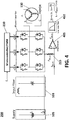
- Figure 4 shows the control circuit (200) previously shown in figure 2 comprising means for calculating a DC current consumption I S , the means comprises signal processing elements to obtain the DC current consumption I S of the BLDC motor (130).
- the DC current consumption I S can be used as input for the microcontroller/PWM block (210) as shown in the figure.
- These signal processing elements comprise an amplifier (405) to amplify the voltage V shunt and perform an offset correction and a low pass filter (410) to filter the voltage signal V shunt from the amplifier (405).
- an output voltage V O is obtained from the low pass filter (410) and the DC current consumption of the BLDC motor I S is obtained based on said voltage V O and according to the equation 1.
- Figure 5 shows the control circuit (300) previously shown in figure 3 further comprising means for calculating a DC current consumption I S , the means comprises signal processing elements to obtain the DC current consumption I S of the BLDC motor (130).
- the DC current consumption I S can also be used as input for the microcontroller/PWM block (310) as in figure 4 .
- the means for calculating a DC current consumption I S comprises three shunt resistors R Sh 1, R Sh2 and R Sh 3 .
- the signal processing elements comprise three amplifiers (505, 510, 515) to amplify three measured voltage levels V Sh 1 V Sh 2 and V Sh 3 corresponding to the shunts resistors R Sh1 , R Sh2 and R Sh 3 , respectively and to perform an offset correction of the voltage levels.
- a low pass filter is also included as part of the control circuit (300) to filter the total voltage V ShT in order to obtain an output voltage V O .
- the DC current consumption of the BLDC motor I S is obtained based on said voltage V O and according to the equation 2.
Landscapes
- Engineering & Computer Science (AREA)
- Power Engineering (AREA)
- Physics & Mathematics (AREA)
- General Physics & Mathematics (AREA)
- Control Of Motors That Do Not Use Commutators (AREA)
Abstract
Description
- The present invention refers to power supply control circuits for BLDC motors having means to calculate a DC current consumption of the BLDC motor based on the processing of a phase current signal of the BLDC motor.
- The BLDC motor is becoming increasingly popular in sectors such as automotive (particularly electric vehicles (EV)), heating, ventilation, and air conditioning (HVAC), in white goods and industrial goods because it does away with the mechanical brush used in traditional motors. This characteristic makes the BLDC motors more reliable and increases its service life.
- Another advantage of a BLDC motor is that it can be made smaller and lighter than a brush type motor with the same power output, making the BLDC motors suitable for applications where space is tight.
- The microcontroller of the control circuit of the BLDC motor may be configured to energize the stator coils of the BLDC at the correct moment by implementing a control algorithm. Precise timing allows for accurate speed and torque control, as well as ensuring the BLDC motor runs at peak efficiency. In this respect, the microcontroller may receive system current values as inputs and signals from position sensors (as e.g. hall sensors that indicate the position of the motor rotor) to implement the control algorithm.
- Current values can be measured and used as input for the control algorithm implemented by the microcontroller: Precise motor control performed by the control circuit of the BLDC represents a very significant condition for the correct performance of the BLDC motor. Whether for electronic power steering, electronic stability control, automatic braking systems, or for the self-driving vehicle, precise motor control may be required to ensure safe and efficient operation. Hence, currents can be measured to collect information primarily on the motor torque as the current measurements can be directly proportional to the motor torque.
- Current measurements can also be used to determine the speed at which the motor is turning. Such speed information can be calculated by understanding how the control algorithm affects the current level applied in the BLDC motor. In this respect, the measurement of phase motor currents may be required as an input variable for the control algorithm implemented by the microcontroller. Therefore, the precise measurement of the phase motor currents can improve the motor control solution.
- Furthermore, currents can be measured for fault protection: Current measurements may be used to detect when an overcurrent condition occurs allowing the system to take action to prevent a potential damage in the BLDC motor.
- Current brushless DC motor control circuits may include 1 to 3 shunt resistors to measure the phase current that can be used as input for the control algorithm implemented by the microcontroller. Some algorithms may require the measurement of the DC current consumption IS. In order to measure the current IS , an additional shunt (101, 102) can be included either in the positive battery input (A) or in the battery return (B) (i.e. in the DC link) as shown in
figure 1 that represents a conventional power supply control circuit (100) of a BLDC motor. However, the type of shunt resistors (101, 102) imply additional unwanted power consumption and heat dissipation in the system. - Furthermore, the power supply control circuit (100) of
figure 1 can comprise a DC source (105), an input AC filter (103), in particular a LC filter, a microcontroller/PWM block (110) that represents a pulse width modulation (PWM) generator that generates a PWM signal to a three-phase inverter (120) and a microcontroller implementing a control algorithm that controls the input current in the brushless DC motor (130). The three-phase inverter (120) comprises six switches for high-power switching to feed current to the DC motor (130). Hence, the output from the block (110) comprises pulse width modulated (PWM) signals that determine the average voltage and average current applied to the three coils of the BLDC motor having a "Y" formation as shown infigure 1 in order to control motor speed and motor torque. Furthermore, the BLDC motor (130) may use three hall-effect sensors not shown in the figure to indicate rotor position. The rotor itself uses several pairs of permanent magnets to generate the magnetic flux. - Hence, a power supply control circuit for a BLDC that uses a procedure for measuring the input DC current consumption IS for the control algorithm other than using shunt resistors in the DC link and thus avoids additional power consumption and heat dissipation and maximizes the performance of the motor-control system is desired.
- The present invention proposes BLDC power supply control circuit that can measure the DC current consumption of the motor IS without the requirement of establishing shunt resistors (101, 102) in the DC link of the power supply in contrast to current implementations. In this respect, a measured phase current signal can be adequately processed in order to obtain the desired DC current consumption that can be used as input for a control algorithm implemented by a microcontroller of the power supply control circuit. Therefore, the proposed control circuit avoids additional power consumption
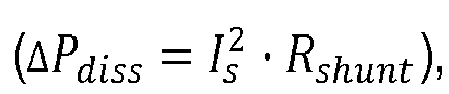
- Hence, in a main aspect of the present invention, it is proposed a power supply control circuit for a three-phase brushless DC (BLDC) comprising means for calculating a DC current consumption IS based on a phase current signal Ishunt of the BLDC motor. The calculated DC current consumption IS may be used by a control algorithm for controlling the BLDC motor control or reported to a master controller for performing additional actions as e.g. overcurrent protection.
- Hence, the means for calculating a DC current consumption IS in the power supply control circuit comprises a shunt resistor Rshunt for phase current sensing having a voltage Vshunt that corresponds to a total phase current signal Ishunt of the three phase BLDC motor across the shunt resistor Rshunt . In particular, the shunt resistor Rshunt can be used to perform low-side phase current sensing as shown in
figures 2 and3 . In this regard, low-side phase sensing allows for easier determination of the motor phase currents, but it is not an exact equivalent, an error is potentially introduced relative to the true phase current. Low-side phase sensing also introduces a ground variation of the motor relative to system ground. - Furthermore, the means for calculating a DC current consumption IS in the power supply control circuit comprises an amplifier to amplify the input voltage Vshunt and perform an offset correction of the input voltage Vshunt .The power supply control circuit also comprises a low pass filter to filter the amplified voltage signal Vshunt to obtain a filtered output voltage VO. The filtered output voltage VO. may be fed into an analogue to digital converter (ADC) (which may or may not be included into the microcontroller itself) to calculate the input DC current consumption IS from the voltage VO . value.
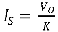
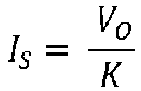
- Hence, the DC current consumption of the BLDC motor IS can be obtained according to the following equation:

- Where Gain is the amplification factor of the amplifier to amplify the input voltage Vshunt.
Thus, shunt resistors (101, 102) used to measure the DC current consumption of the BLDC motor IS as shown infigure 1 are avoided. - In another aspect of the present invention, it is proposed a further example of a power supply control circuit for a BLDC comprising means for calculating a DC current consumption IS according to the present disclosure. The power supply control circuit uses means for performing phase current sensing. The means comprises three shunt resistors, e.g. RSh1 , RSh2 and RSh3 . The means of the power supply control circuit also comprises means for shunt signal amplification and offset correction, means for summation of the three shunt signals and low-pass signal filter.
- Hence, it is proposed an alternative BLDC motor power supply control circuit comprising means for calculating the DC current consumption IS based on three phase current signals I Sh1 I Sh2 and I Sh3 of the BLDC motor.
- Hence, the means of the power supply control circuit according to the second aspect of the present invention comprises three shunt resistors RSh1 RSh2 and R Sh3 for the three phases of the BLDC motor. Furthermore, the means of the power supply control circuit comprises three amplifiers to amplify three measured voltage signals V Sh1, V Sh2 and V Sh3 corresponding to the phase current signals I Sh1, I Sh2 and I Sh3 of the BLDC motor across the shunt resistors RSh1 RSh2 and R Sh3, respectively and perform an offset correction of the voltages V Sh1 V Sh2 and V Sh3. The total phase current signal can be calculated as IShT = I sh1 + I sh2 + I sh3.
- The means of the power supply control circuit further comprises a summing amplifier to sum the three voltage signals V Sh1 V Sh2 and V Sh3 and a low pass filter that filters VShT and obtains an output voltage VO. Therefore VShT = V Sh1 + V Sh2 + V Sh3.
- Hence, the DC current consumption of the BLDC motor IS can be obtained according to the following equation:

- The GainTotal represents the total amplification factor of the three amplifiers to amplify three measured voltage signals V Sh1, V Sh2 and V Sh3.
The RTotal is the equivalent resistance of RSh1 , RSh2 and R Sh3 :
- In some examples, the power supply control circuit comprises an AC filter comprising a capacitor and an inductance as shown in the figures.
- In another aspect, it is proposed a method for calculating a DC current consumption IS of a three phase brushless DC (BLDC) motor, the method performed by the motor microcontroller of the power supply control circuit. The method comprises a step for amplifying a voltage signal Vshunt corresponding to a total phase current signal Ishunt of the BLDC motor across a shunt resistor Rshunt . The shunt resistor Rshunt can measure low-side phase current. The method comprises a step for performing an offset correction of the voltage signal Vshunt. The method further comprises a step for obtaining an output voltage VO by low-pass filtering the amplified voltage signal Vshunt . Finally, the method comprises a step for obtaining the DC current consumption IS based on the output voltage VO and according to
equation 1. In an example, the motor microcontroller can be configured to implement a control algorithm for controlling the BLDC motor based at least on the calculated IS . In another example, a master controller may use the calculated IS for performing e.g. overcurrent protection. - In another aspect, it is proposed a second method for calculating a DC current consumption IS of a three phase brushless DC (BLDC) motor, the method is also performed by the motor microcontroller of the power supply control circuit. The method comprises a step for amplifying three voltage signals V Sh1 V Sh2 and V Sh3 corresponding to three phase current signals I Sh1 I Sh2 I Sh3 of the BLDC motor across shunt resistors RSh1 , R Sh2 and R Sh3, respectively. In particular, the shunt resistors can measure low-side phase currents. The method comprises a step for performing offset correction of the three voltage signals V Sh1 V Sh2 and V Sh3. The method comprises obtaining a total tension VShT by summing the three voltage signals V Sh1 V Sh2 and V Sh3 and obtaining a filtered voltage VO by low-pass filtering the total tension VShT. Finally the DC current consumption IS is obtained based on the output voltage VO and according to the equation 2.
- For a better understanding the above explanation and for the sole purpose of providing an example, some non-limiting drawings are included that schematically depict a practical embodiment.
-
Figure 1 shows a conventional BLDC power supply control circuit. -
Figure 2 shows a first example of a BLDC power supply control circuit according to the present disclosure. -
Figure 3 shows a second example of a BLDC power supply control circuit according to the present disclosure. -
Figure 4 shows the first example of a BLDC power supply control circuit according to the present disclosure. -
Figures 5 shows the second example of a BLDC power supply control circuit according to the present disclosure. -
Figure 2 shows a power supply control circuit (200) for a BLDC (130) having a "Y" formation. In another example, the BLDC (130) can have a "Delta" formation. The advantages of the configuration of the power supply control circuit (200) are cost reduction, the PCB area for placement of the control circuit is smaller compared to other configurations. Furthermore, one single ADC converters is needed. The control circuit (200) comprises a microcontroller/PWM control block (210) that generates a PWM signal for a power inverter (120) which produces an AC electric current that feeds the BLDC motor (130). The microcontroller/PWM block (210) controls current in the brushless DC motor (130) based on a control algorithm implemented by the microcontroller. The control circuit (200) comprises means for calculating a DC current consumption IS based on a phase current signal Ishunt of the BLDC motor, the means comprises a Rshunt (215) for measuring low-side current sensing and an input AC filter (103). In order to obtain the DC current consumption IS , the voltage Vshunt corresponding to the current IShunt across Rshunt (215) is measured, amplified, offset corrected and filtered as shown infigure 4 . The DC current consumption IS is calculated according toequation 1. -
Figure 3 shows a power supply control circuit (300) for the BLDC (130). The advantages of the configuration of the power supply control circuit (300) are that this configuration can obtain more precise phase currents readings and involve less acoustic noise and less total harmonic distortion (THD). Hence, the control algorithm can be improved when calculated DC current consumption IS is used to implement the control algorithm. The control circuit (300) comprises a microcontroller/PWM generator control block (310) that generates six PWM signals for the power inverter (120) that feeds the DC motor (130). The microcontroller/PWM generator block (310) controls current in the brushless DC motor (130) based on the control algorithm. In some examples, the DC current consumption IS of the BLDC motor (130) can be used as input to the control algorithm. The control circuit (300) comprises means for calculating the DC current consumption IS based on a phase current signal IShT, the means comprises a three shunt resistors R Sh1, RSh2 and R Sh3 for measuring each phase current and an input AC filter (103). In order to obtain the DC current consumption IS , three voltages V Sh1 V Sh2 and V Sh3 are measured that correspond to the currents I Sh1, ISh2 and I Sh3 across the three shunt resistors RSh1 RSh2 and R Sh3, respectively. The total phase current signal can be calculated as IShT = I sh1 + I sh2 + I sh3. Furthermore, the three voltages V Sh1 V Sh2 and V Sh3 are amplified, offset corrected, summed and filtered as shown infigure 5 . The DC current consumption IS is calculated according to equation 2. -
Figure 4 shows the control circuit (200) previously shown infigure 2 comprising means for calculating a DC current consumption IS , the means comprises signal processing elements to obtain the DC current consumption IS of the BLDC motor (130). In this example, the DC current consumption IS can be used as input for the microcontroller/PWM block (210) as shown in the figure. These signal processing elements comprise an amplifier (405) to amplify the voltage Vshunt and perform an offset correction and a low pass filter (410) to filter the voltage signal Vshunt from the amplifier (405). Hence, an output voltage VO is obtained from the low pass filter (410) and the DC current consumption of the BLDC motor IS is obtained based on said voltage VO and according to theequation 1. -
Figure 5 shows the control circuit (300) previously shown infigure 3 further comprising means for calculating a DC current consumption IS , the means comprises signal processing elements to obtain the DC current consumption IS of the BLDC motor (130). In this example, the DC current consumption IS can also be used as input for the microcontroller/PWM block (310) as infigure 4 . As previously mentioned, the means for calculating a DC current consumption IS comprises three shunt resistors R Sh1, RSh2 and R Sh3. The signal processing elements comprise three amplifiers (505, 510, 515) to amplify three measured voltage levels V Sh1 V Sh2 and V Sh3 corresponding to the shunts resistors RSh1 , RSh2 and R Sh3, respectively and to perform an offset correction of the voltage levels. Furthermore, the signal processing elementscomprise a summation module as e.g. a summing amplifier (not drawn in the figure) but represented by reference (520) to obtain a total voltage VShT = V Sh1 + V Sh2 + V Sh3. A low pass filter is also included as part of the control circuit (300) to filter the total voltage VShT in order to obtain an output voltage VO. Finally, the DC current consumption of the BLDC motor IS is obtained based on said voltage VO and according to the equation 2. - Even though reference has been made to a specific embodiment of the invention, it is obvious for a person skilled in the art that the BLDC power supply control circuit architectures described herein are susceptible to numerous variations and modifications, and that all the details mentioned can be substituted for other technically equivalent ones without departing from the scope of protection defined by the attached claims.
Claims (7)
- A power supply control circuit (200) of a three-phase brushless DC (BLDC) motor (130), characterized in that the control circuit (200) comprises means for calculating the DC current consumption IS based on a phase current signal Ishunt of the BLDC motor (130), the means comprising:a shunt resistor (215) Rshunt ;an amplifier (405); anda low pass filter (410),wherein the amplifier (405) is configured to amplify and perform an offset correction of a voltage Vshunt that corresponds to the current Ishunt across the resistor (215) Rshunt ;wherein the low pass filter (410) is configured to provide a filtered voltage VO of the voltage Vshunt , andwherein the DC current IS is calculated according to the following equation:

- A power supply control circuit (300) of a three-phase brushless DC (BLDC) motor (130) characterized in that the control circuit (300) comprises means for calculating the DC current consumption IS based on three phase current signals I Sh1 I Sh2 and I Sh3 of the BLDC motor (130), the means comprising:three shunt resistors (315, 320, 325) RSh1 , RSh2 and R Sh3 ;three amplifiers (505, 510, 515);a summing amplifier (520); anda low pass filter (525)wherein the three amplifiers (505, 510, 515) are configured to amplify and perform an offset correction of voltages V Sh1, V Sh2 and V Sh3 that correspond to the currents I Sh1 I Sh2 and I Sh3 across the three shunt resistors (315, 320, 325) RSh1 , RSh2 and R Sh3; wherein the summing amplifier (520) is configured to provide a summed voltage VShT ; wherein the low pass filter (525) is configured to provide a filtered voltage VO of the voltage VShT , andwherein the DC current consumption of the BLDC motor IS is calculated according to the following equation:
- The power supply control circuit according to any of the preceding claims further comprising an AC filter.
- A method for calculating a DC current consumption IS of a three phase brushless DC (BLDC), the method performed by a microcontroller of a power supply control circuit of the BLDC motor, the method comprising:amplifying a voltage signal Vshunt corresponding to a phase current signal Ishunt of the BLDC motor across a shunt resistor Rshunt for phase current sensing;performing offset correction of the voltage signal Vshunt;obtaining an output voltage VO by low-pass filtering the amplified voltage signal Vshunt; andcalculating the DC current consumption IS according to the following equation:
- The method according to claim 4, further comprising implementing a control algorithm for controlling the BLDC motor based at least on the calculated IS .
- A method for calculating a DC current consumption IS of a three phase brushless DC (BLDC) motor, the method performed by a microcontroller of a power supply control circuit of the BLDC motor, the method comprising:amplifying three voltage signals V Sh1, V Sh2 and V Sh3 corresponding to three phase current signals I Sh1 , I Sh2 and I Sh3 of the BLDC motor across three shunt resistors RSh1, R Sh2 and R Sh3 for phase current sensing, respectively;performing an offset correction of the three voltage signals V Sh1, V Sh2 and V Sh3; obtaining a total tension VShT by summing the three voltage signals V Sh1, V Sh2 and V Sh3;obtaining a filtered voltage VO by low-pass filtering the total tension VShT ; andcalculating the DC current consumption IS according to the following equation:
 wherein K = RTotal * GainTotal ,wherein RTotal is the equivalent resistance of RSh1 , RSh2 and R Sh3 and GainTotal is the total amplification factor of the three amplifiers (505, 510, 515).
 - The method according to claim 6, further comprising implementing a control algorithm for controlling the BLDC motor based at least on the calculated IS .
Priority Applications (4)
| Application Number | Priority Date | Filing Date | Title |
|---|---|---|---|
| EP19382023.0A EP3683587A1 (en) | 2019-01-15 | 2019-01-15 | Power supply control circuits for brushless dc (bldc) motors |
| CN202080009288.2A CN113302504A (en) | 2019-01-15 | 2020-01-10 | Power supply control circuit for brushless DC (BLDC) motor |
| PCT/EP2020/050495 WO2020148173A1 (en) | 2019-01-15 | 2020-01-10 | Power supply control circuits for brushless dc (bldc) motors |
| US17/377,156 US11863106B2 (en) | 2019-01-15 | 2021-07-15 | Power supply control circuits for brushless DC (BLDC) motors |
Applications Claiming Priority (1)
| Application Number | Priority Date | Filing Date | Title |
|---|---|---|---|
| EP19382023.0A EP3683587A1 (en) | 2019-01-15 | 2019-01-15 | Power supply control circuits for brushless dc (bldc) motors |
Publications (1)
| Publication Number | Publication Date |
|---|---|
| EP3683587A1 true EP3683587A1 (en) | 2020-07-22 |
Family
ID=65228487
Family Applications (1)
| Application Number | Title | Priority Date | Filing Date |
|---|---|---|---|
| EP19382023.0A Withdrawn EP3683587A1 (en) | 2019-01-15 | 2019-01-15 | Power supply control circuits for brushless dc (bldc) motors |
Country Status (4)
| Country | Link |
|---|---|
| US (1) | US11863106B2 (en) |
| EP (1) | EP3683587A1 (en) |
| CN (1) | CN113302504A (en) |
| WO (1) | WO2020148173A1 (en) |
Families Citing this family (2)
| Publication number | Priority date | Publication date | Assignee | Title |
|---|---|---|---|---|
| US20250334620A1 (en) * | 2024-04-29 | 2025-10-30 | Spellman High-Voltage Electronics Corporation | Measurement of load capacitance or impedance in high-voltage dc power supplies |
| CN120315048B (en) * | 2025-06-16 | 2025-09-19 | 吉林大学 | Aviation electromagnetic emission current measurement system |
Citations (2)
| Publication number | Priority date | Publication date | Assignee | Title |
|---|---|---|---|---|
| EP2420850A1 (en) * | 2009-04-17 | 2012-02-22 | Daikin Industries, Ltd. | Current-sensing circuit and air-conditioning device provided therewith |
| US20120163046A1 (en) * | 2009-09-28 | 2012-06-28 | Hiroshi Hibino | Phase current detection device and power conversion device using the same |
Family Cites Families (8)
| Publication number | Priority date | Publication date | Assignee | Title |
|---|---|---|---|---|
| JP5170208B2 (en) | 2010-10-22 | 2013-03-27 | 富士電機株式会社 | Current detection circuit for power semiconductor devices |
| CN202260404U (en) * | 2011-09-28 | 2012-05-30 | 上海大全赛奥法电气科技有限公司 | A low-voltage motor protection controller |
| US9263982B2 (en) | 2013-03-15 | 2016-02-16 | Steering Solutions Ip Holding Corporation | Motor control system having common-mode voltage compensation |
| JP6366738B2 (en) * | 2015-01-05 | 2018-08-01 | 三菱電機株式会社 | Power converter |
| KR20170067934A (en) * | 2015-12-08 | 2017-06-19 | 현대자동차주식회사 | Device for controlling motor |
| KR102441606B1 (en) | 2017-05-25 | 2022-09-07 | 현대모비스 주식회사 | Motor control system and method therefor |
| US10374533B2 (en) * | 2017-11-21 | 2019-08-06 | Infineon Technologies Austria Ag | Block commutation to reduce inverter losses for BLDC drives |
| KR102014185B1 (en) | 2018-03-27 | 2019-08-26 | 엘에스산전 주식회사 | Apparatus for determining peak current in inverter |
-
2019
- 2019-01-15 EP EP19382023.0A patent/EP3683587A1/en not_active Withdrawn
-
2020
- 2020-01-10 WO PCT/EP2020/050495 patent/WO2020148173A1/en not_active Ceased
- 2020-01-10 CN CN202080009288.2A patent/CN113302504A/en active Pending
-
2021
- 2021-07-15 US US17/377,156 patent/US11863106B2/en active Active
Patent Citations (2)
| Publication number | Priority date | Publication date | Assignee | Title |
|---|---|---|---|---|
| EP2420850A1 (en) * | 2009-04-17 | 2012-02-22 | Daikin Industries, Ltd. | Current-sensing circuit and air-conditioning device provided therewith |
| US20120163046A1 (en) * | 2009-09-28 | 2012-06-28 | Hiroshi Hibino | Phase current detection device and power conversion device using the same |
Also Published As
| Publication number | Publication date |
|---|---|
| US20210344290A1 (en) | 2021-11-04 |
| US11863106B2 (en) | 2024-01-02 |
| CN113302504A (en) | 2021-08-24 |
| WO2020148173A1 (en) | 2020-07-23 |
Similar Documents
| Publication | Publication Date | Title |
|---|---|---|
| US7956561B2 (en) | Rotor position sensing system of brushless motor | |
| JP5055246B2 (en) | Control device for rotating electrical machine | |
| US11863106B2 (en) | Power supply control circuits for brushless DC (BLDC) motors | |
| EP3118990A1 (en) | Motor control device, electric power steering device using same, and vehicle | |
| JP4517793B2 (en) | Permanent magnet synchronous motor control device and module | |
| CN104079229B (en) | Motor control system having common-mode voltage compensation | |
| JP5844365B2 (en) | Measurement circuit | |
| EP3950403A1 (en) | Drive device for permanent-magnet synchronous machine, torque compensation method for permanent-magnet synchronous machine, and electric vehicle | |
| EP2420850B1 (en) | Current-sensing circuit and air-conditioning device provided therewith | |
| US10906580B2 (en) | Method for detecting a torque control defect of an electric motor of a power-steering system of a motor vehicle | |
| US10988033B2 (en) | Control system for a vehicle | |
| JP5189627B2 (en) | Power converter | |
| JP4259219B2 (en) | Motor drive device and automobile equipped with the same | |
| EP4175153A1 (en) | Inverter device | |
| US10547265B2 (en) | System and method for controlling motor | |
| JP2003324985A (en) | Motor control device | |
| JP5525405B2 (en) | Current detection circuit, motor drive device | |
| US20200007066A1 (en) | Power conversion device for electric vehicle | |
| WO2021148308A1 (en) | Power supply control circuits with shunt resistors for synchronous motors | |
| JP2006345683A (en) | Current detector | |
| KR102795621B1 (en) | A method for measuring the power consumption of a three-phase power electronics system, and a circuit for this purpose | |
| JP3329673B2 (en) | Induction motor control device | |
| US20130134963A1 (en) | Motor Control Circuitry | |
| JP2010063210A (en) | Current detecting circuit for ac motor, and driving circuit for linear motor |
Legal Events
| Date | Code | Title | Description |
|---|---|---|---|
| PUAI | Public reference made under article 153(3) epc to a published international application that has entered the european phase |
Free format text: ORIGINAL CODE: 0009012 |
|
| STAA | Information on the status of an ep patent application or granted ep patent |
Free format text: STATUS: THE APPLICATION HAS BEEN PUBLISHED |
|
| AK | Designated contracting states |
Kind code of ref document: A1 Designated state(s): AL AT BE BG CH CY CZ DE DK EE ES FI FR GB GR HR HU IE IS IT LI LT LU LV MC MK MT NL NO PL PT RO RS SE SI SK SM TR |
|
| AX | Request for extension of the european patent |
Extension state: BA ME |
|
| STAA | Information on the status of an ep patent application or granted ep patent |
Free format text: STATUS: REQUEST FOR EXAMINATION WAS MADE |
|
| 17P | Request for examination filed |
Effective date: 20210119 |
|
| RBV | Designated contracting states (corrected) |
Designated state(s): AL AT BE BG CH CY CZ DE DK EE ES FI FR GB GR HR HU IE IS IT LI LT LU LV MC MK MT NL NO PL PT RO RS SE SI SK SM TR |
|
| STAA | Information on the status of an ep patent application or granted ep patent |
Free format text: STATUS: EXAMINATION IS IN PROGRESS |
|
| 17Q | First examination report despatched |
Effective date: 20220128 |
|
| STAA | Information on the status of an ep patent application or granted ep patent |
Free format text: STATUS: THE APPLICATION IS DEEMED TO BE WITHDRAWN |
|
| 18D | Application deemed to be withdrawn |
Effective date: 20220809 |