EP3683461A1 - Drive shafts with enhanced bending flexibility - Google Patents
Drive shafts with enhanced bending flexibility Download PDFInfo
- Publication number
- EP3683461A1 EP3683461A1 EP19207528.1A EP19207528A EP3683461A1 EP 3683461 A1 EP3683461 A1 EP 3683461A1 EP 19207528 A EP19207528 A EP 19207528A EP 3683461 A1 EP3683461 A1 EP 3683461A1
- Authority
- EP
- European Patent Office
- Prior art keywords
- deformations
- drive shaft
- set forth
- grooves
- spaced
- Prior art date
- Legal status (The legal status is an assumption and is not a legal conclusion. Google has not performed a legal analysis and makes no representation as to the accuracy of the status listed.)
- Granted
Links
Images




Classifications
-
- F—MECHANICAL ENGINEERING; LIGHTING; HEATING; WEAPONS; BLASTING
- F16—ENGINEERING ELEMENTS AND UNITS; GENERAL MEASURES FOR PRODUCING AND MAINTAINING EFFECTIVE FUNCTIONING OF MACHINES OR INSTALLATIONS; THERMAL INSULATION IN GENERAL
- F16C—SHAFTS; FLEXIBLE SHAFTS; ELEMENTS OR CRANKSHAFT MECHANISMS; ROTARY BODIES OTHER THAN GEARING ELEMENTS; BEARINGS
- F16C1/00—Flexible shafts; Mechanical means for transmitting movement in a flexible sheathing
- F16C1/02—Flexible shafts; Mechanical means for transmitting movement in a flexible sheathing for conveying rotary movements
-
- F—MECHANICAL ENGINEERING; LIGHTING; HEATING; WEAPONS; BLASTING
- F16—ENGINEERING ELEMENTS AND UNITS; GENERAL MEASURES FOR PRODUCING AND MAINTAINING EFFECTIVE FUNCTIONING OF MACHINES OR INSTALLATIONS; THERMAL INSULATION IN GENERAL
- F16C—SHAFTS; FLEXIBLE SHAFTS; ELEMENTS OR CRANKSHAFT MECHANISMS; ROTARY BODIES OTHER THAN GEARING ELEMENTS; BEARINGS
- F16C3/00—Shafts; Axles; Cranks; Eccentrics
- F16C3/02—Shafts; Axles
- F16C3/026—Shafts made of fibre reinforced resin
-
- B—PERFORMING OPERATIONS; TRANSPORTING
- B64—AIRCRAFT; AVIATION; COSMONAUTICS
- B64C—AEROPLANES; HELICOPTERS
- B64C27/00—Rotorcraft; Rotors peculiar thereto
- B64C27/04—Helicopters
- B64C27/12—Rotor drives
-
- B—PERFORMING OPERATIONS; TRANSPORTING
- B64—AIRCRAFT; AVIATION; COSMONAUTICS
- B64C—AEROPLANES; HELICOPTERS
- B64C27/00—Rotorcraft; Rotors peculiar thereto
- B64C27/04—Helicopters
- B64C27/12—Rotor drives
- B64C27/14—Direct drive between power plant and rotor hub
-
- F—MECHANICAL ENGINEERING; LIGHTING; HEATING; WEAPONS; BLASTING
- F16—ENGINEERING ELEMENTS AND UNITS; GENERAL MEASURES FOR PRODUCING AND MAINTAINING EFFECTIVE FUNCTIONING OF MACHINES OR INSTALLATIONS; THERMAL INSULATION IN GENERAL
- F16C—SHAFTS; FLEXIBLE SHAFTS; ELEMENTS OR CRANKSHAFT MECHANISMS; ROTARY BODIES OTHER THAN GEARING ELEMENTS; BEARINGS
- F16C3/00—Shafts; Axles; Cranks; Eccentrics
- F16C3/02—Shafts; Axles
-
- F—MECHANICAL ENGINEERING; LIGHTING; HEATING; WEAPONS; BLASTING
- F16—ENGINEERING ELEMENTS AND UNITS; GENERAL MEASURES FOR PRODUCING AND MAINTAINING EFFECTIVE FUNCTIONING OF MACHINES OR INSTALLATIONS; THERMAL INSULATION IN GENERAL
- F16C—SHAFTS; FLEXIBLE SHAFTS; ELEMENTS OR CRANKSHAFT MECHANISMS; ROTARY BODIES OTHER THAN GEARING ELEMENTS; BEARINGS
- F16C2208/00—Plastics; Synthetic resins, e.g. rubbers
- F16C2208/02—Plastics; Synthetic resins, e.g. rubbers comprising fillers, fibres
-
- F—MECHANICAL ENGINEERING; LIGHTING; HEATING; WEAPONS; BLASTING
- F16—ENGINEERING ELEMENTS AND UNITS; GENERAL MEASURES FOR PRODUCING AND MAINTAINING EFFECTIVE FUNCTIONING OF MACHINES OR INSTALLATIONS; THERMAL INSULATION IN GENERAL
- F16C—SHAFTS; FLEXIBLE SHAFTS; ELEMENTS OR CRANKSHAFT MECHANISMS; ROTARY BODIES OTHER THAN GEARING ELEMENTS; BEARINGS
- F16C2208/00—Plastics; Synthetic resins, e.g. rubbers
- F16C2208/20—Thermoplastic resins
-
- F—MECHANICAL ENGINEERING; LIGHTING; HEATING; WEAPONS; BLASTING
- F16—ENGINEERING ELEMENTS AND UNITS; GENERAL MEASURES FOR PRODUCING AND MAINTAINING EFFECTIVE FUNCTIONING OF MACHINES OR INSTALLATIONS; THERMAL INSULATION IN GENERAL
- F16C—SHAFTS; FLEXIBLE SHAFTS; ELEMENTS OR CRANKSHAFT MECHANISMS; ROTARY BODIES OTHER THAN GEARING ELEMENTS; BEARINGS
- F16C2208/00—Plastics; Synthetic resins, e.g. rubbers
- F16C2208/80—Thermosetting resins
- F16C2208/82—Composites, i.e. fibre reinforced thermosetting resins
-
- F—MECHANICAL ENGINEERING; LIGHTING; HEATING; WEAPONS; BLASTING
- F16—ENGINEERING ELEMENTS AND UNITS; GENERAL MEASURES FOR PRODUCING AND MAINTAINING EFFECTIVE FUNCTIONING OF MACHINES OR INSTALLATIONS; THERMAL INSULATION IN GENERAL
- F16C—SHAFTS; FLEXIBLE SHAFTS; ELEMENTS OR CRANKSHAFT MECHANISMS; ROTARY BODIES OTHER THAN GEARING ELEMENTS; BEARINGS
- F16C2240/00—Specified values or numerical ranges of parameters; Relations between them
- F16C2240/40—Linear dimensions, e.g. length, radius, thickness, gap
- F16C2240/60—Thickness, e.g. thickness of coatings
-
- F—MECHANICAL ENGINEERING; LIGHTING; HEATING; WEAPONS; BLASTING
- F16—ENGINEERING ELEMENTS AND UNITS; GENERAL MEASURES FOR PRODUCING AND MAINTAINING EFFECTIVE FUNCTIONING OF MACHINES OR INSTALLATIONS; THERMAL INSULATION IN GENERAL
- F16C—SHAFTS; FLEXIBLE SHAFTS; ELEMENTS OR CRANKSHAFT MECHANISMS; ROTARY BODIES OTHER THAN GEARING ELEMENTS; BEARINGS
- F16C2326/00—Articles relating to transporting
- F16C2326/01—Parts of vehicles in general
- F16C2326/06—Drive shafts
-
- F—MECHANICAL ENGINEERING; LIGHTING; HEATING; WEAPONS; BLASTING
- F16—ENGINEERING ELEMENTS AND UNITS; GENERAL MEASURES FOR PRODUCING AND MAINTAINING EFFECTIVE FUNCTIONING OF MACHINES OR INSTALLATIONS; THERMAL INSULATION IN GENERAL
- F16C—SHAFTS; FLEXIBLE SHAFTS; ELEMENTS OR CRANKSHAFT MECHANISMS; ROTARY BODIES OTHER THAN GEARING ELEMENTS; BEARINGS
- F16C2326/00—Articles relating to transporting
- F16C2326/43—Aeroplanes; Helicopters
Definitions
- This application relates to drive shafts with enhanced flexibility.
- Drive shafts are utilized in any number of applications. Typically, a drive shaft connects a source of drive to an item to be driven. Drive shafts are utilized in aerospace applications. One particular application is to drive propellers such as are associated with a helicopter. It is known that the drive shaft input might become misaligned with the drive shaft output during operation. Thus, some flexibility is desirable along the drive shaft.
- Drive shafts have historically been provided as a single tubular member with flexible diaphragms at each end to allow for some flexibility between the input and the output.
- a drive shaft has a tubular portion extending between axial ends and is hollow. There are deformations on the tubular portions. The deformations extend for a circumferential extent that is less than 180° about a central axis of the tubular portion.
- Figure 1 shows a drive arrangement 20, which drives a component 22 through a drive input 24, and having a drive shaft 26 connecting the input 24 to the output 22.
- a plurality of grooves or detents 28 and 30 are formed on an outer peripheral surface of a shaft portion 26.
- the grooves 28 and 30 extend for a limited circumferential length about an axis of rotation Z of the drive shaft 26. In fact, the grooves 28 and 30 extend for less than 180° about the axis of rotation Z.
- Figure 2A shows a tubular portion 31 of the shaft 26 having the grooves or detents 28 and 30. While grooves are specifically disclosed with regard to the apparatus features of this disclosure, bumps 17 such as mentioned above which extend radially outwardly can be substituted for the grooves in all embodiments.
- Figure 2B is a cross-sectional view through space portions of the repeated grooves 28.
- Figure 2C is a cross-sectional view through the grooves 30.
- groove sets are positioned in general alignment, but spaced axially from each other.
- the circumferential extent of the grooves 30 extends across a space between ends 19 of spaced grooves 28.
- the grooves 28 also extend through a space between the ends 19 of the grooves 30.
- the ends 19 of the grooves 30 may extend circumferentially beyond the ends 19 of the grooves 28, and vice versa.
- the ends 19 of the grooves 30 and the ends 19 of the grooves 28 may end before the circumferential location of the other ends 19.
- the deformations include at least two axially spaced deformation sets, with a first set having deformations between first set circumferential ends and a second set extending between second set circumferential ends. Deformations in the second set extend at least partially into a circumferential space between the first circumferential ends
- the grooves deform a wall of the preform, but do not cut, or extend, through to an inner surface.
- the grooves or detents 28 (although this is also true of the detents 30, and the other detents to be disclosed below) also deform an inner peripheral surface 13 of the tubular portion 31.
- the groove 28 is showing having an inwardly extending portion 15 deformed into the inner surface 13.
- the deformations need not extend through the entire thickness of the tubular portion 31, and do not deform, say, the inner surface 13.
- Figure 3A shows diametric cross-section with an embodiment of a groove 28 that is relatively flat at an outer surface 29.
- Figure 3B shows a similar shape to the outer surface 29 of the groove 30.
- Figure 3C shows diametric cross-section with a more complex shape for a groove 128 on a drive shaft 126.
- shape 128 has as an outermost position 129 extending to circumferential ends 131.
- the deformations are formed to have a central location 129 which extends radially further away from the central axis, and the circumferential ends 131 extend in a circumferential direction toward each other.
- Figure 3D has a similar shape for a groove 130.
- Figure 4A shows a first embodiment wherein there is a drive shaft 200 having a portion 203 in a central location that is generally without grooves. Portions adjacent ends 204 have groove sets 202. There are at least a plurality of grooves 202 adjacent the ends 204 spaced by a distance d 1 .
- the spacing distances d 1 can be either the same or variable in the grooved areas. It could be said that a spacing distance d 1 between the grooves 202 at the end portions is greater than a distance d 2 between grooves across the non-groove section 203 having fewer grooves.
- Figure 4B shows a drive shaft embodiment 210 wherein a pair of non-groove portions 203 and 206 extend between the ends 204 of the drive shaft.
- An area with grooves 202 is shown at an intermediate location.
- a distance d 1 between a plurality of grooves in the grooved area is less than a distance between grooves in the non-grooved areas 210.
- the distance d 2 here is also greater than d 1 .
- Figure 4C shows a drive shaft 212 having non-grooved areas 201 with end groove portions 900 and a central groove portion 900.
- a distance between a plurality of grooves in each of the grooved portions 900 is less than a distance between grooves across the portions 201.
- Figure 4D shows a drive shaft 220 wherein the grooves 202 are formed by uniform or variable spacing across an axial length of the drive shaft and between the axial ends 204.
- Figure 5A shows another potential feature wherein a drive shaft 230 has a central portion 236 which is relatively small, and end portions 232 having grooves 234 such as disclosed above. Portions 232 are either radially larger or/and thicker than the central portion 236.
- this may be accomplished by either simply having the outer diameter of the portion 234 be larger than the outer diameter of the portion 236 while keeping the inner diameter 998 of the portions 236 and 234 constant.
- a thickness t 1 of the portion 234 is greater than a radial thickness t 2 of the portion 236. This will provide reinforcement to the area with grooves to mitigate stress concentrations due to the grooves.
- the groove or detent 234 is omitted from this view to simplify the section and better illustrate the relative diameters and/or thicknesses.
- Figure 5C shows another embodiment wherein the thickness t 1 and t 2 of the sections 234' and 236' may be different and their inner diameters 998' and 998" are also different. It should be understood that the inner diameter 998 between the two sections will change in a linear or non-linear fashion as one moves from the two cross-sections of Figure 5B . That is, in the section 999 as shown in Figure 5A , the inner diameter will slope to accommodate the differences between the two sections 234' and 236'.
- Figures 6A and 6B show an embodiment 240 much like that illustrated above with regard to Figure 1 wherein an embodiment 240 much like that illustrated in Figure 1 wherein there are two groove sets 242 and 244.
- Figure 6A shows the first groove set 242 on the shaft 240 wherein the grooves 242 are centered on the axis 243.
- Figure 6B shows the second groove set 244 on the shaft 240 wherein the grooves 244 are centered on an axis 245.
- An angle A is defined between the axes 243 and 245, and the angle A may be approximately 90°.
- Figure 6C shows a drive shaft embodiment 250 having a pair of grooves 252 centered on an axis 254.
- embodiment 250 there are not two axially spaced sets of grooves, but rather three.
- Figure 6D shows grooves 256 centered on axis 258.
- An angle B is defined between axes 254 and 258, and the angle B may be approximately 60°.
- Figure 6E shows another axially spaced cross-section of the drive shaft 250 wherein there are grooves 260 centered on an axis 262.
- Axis 262 is spaced from axis 243 by an angle C.
- Angle C may be approximately 120°, i.e., approximately twice larger than the angle B.
- Embodiments with more than three sets of grooves may be used.
- Figure 7A shows a first embodiment shaft 300 wherein there are two grooves 302 at each axial location in each groove set.
- Figure 7B shows an alternative drive shaft embodiment 304 wherein there are three circumferentially spaced grooves 306 in each groove set.
- Figure 7C shows a drive shaft embodiment 308 wherein there are four circumferentially spaced grooves 310 at each axial location in each groove set.
- the arrangement of grooves circumferentially about a shaft axis Z is similar to the arrangement when only two grooves per the section are used. For example if there are two uniformly positioned grooves shown in Figure 7A , a diametric complimentary cross-section ( Figure 3B ) a rotated at approximately 90°. Similarly in case of three the same, uniformly positioned grooves ( Figure 7B ), there is a corresponding cross-section rotated at 60°. In case of four ( Figure 7C ), uniformly positioned grooves, there is a similar rotation at 45°, and so on. More complex, but similar mutual arrangements can be defined if there are more than two complimentary sets of grooves, for example of a case shown in Figures 6C-6E for three complimentary sets.
- Figure 8A shows a first cross-sectional shape 320 for an individual groove presented in an axial cross-section of the shaft (that is, similar to the Figure 2B section).
- Cross-sectional shape 320 has a generally uniform or non-uniform but concave shape and constant or variable radius R 1 .
- Figure 8B shows an alternative shape 322 wherein there is a central concave portion 321 formed about a constant or variable radius R 2 . There are also convex portions 324 on each side of the portion 321. These convex segments 324 spaced on each end of the concave portion.
- Figure 8C shows another alternative groove shape 330 having a flat portion 326, convex end portions 328 at each end of the groove, and concave portions 327.
- a drive shaft could be said to comprise a tubular portion extending between axial ends and being hollow. Deformations are formed from an outer peripheral surface of the cylindrical shaft portion. The deformations extend for a circumferential extent that is less than 180° about a central axis of the tubular portion.
- the shafts as disclosed above may be formed of the same or different fiber-reinforced polymer matrix composite materials.
- the matrix can be a thermoplastic polymer.
- the matrix can be a thermoset polymer composite.
- Different types of reinforcing fibers such as, for example, carbon fibers, glass fibers, organic fibers, inorganic material (e.g. ceramic) fibers, or their combinations can be used in different embodiments.
- the same or different fabrication processes such as for example, automated fiber placement, filament winding, braiding, wrapping, etc. can be used to make separate composite tubes and diaphragms. Alternatively, this disclosure would also extend to metal shafts.
- Figure 9A shows a tubular portion formed of a thermoplastic shaft preform. Heated molds 402 are brought into contact with compression against the tubular preform 400 to form the grooves 404.
- heated molds are disclosed, with certain materials the molds need not be heated. As an example if a thermoplastic is used heated molds may be used. The molds need not be heated when a thermoset or metal is used. As an example, a mold may be brought into contact with a partially curved thermoset polymer composite preform shaft.
- the molds are generally cylindrical.
- the several shapes of the grooves or detents, as disclosed above, could inform the shape of the molds.
- Figure 9B shows diametric cross-sectional view of a shaft 406 having the grooves 408 formed to be generally flat and extending between circumferentially spaced curved ends 409. This embodiment would be similar to that illustrated in Figures 3A and 3B .
- Figure 10A shows a shaft preform 420 receiving molds 424, which have a curvature to them, and which form the groove areas 422.
- Figure 11 is a flowchart of the methods as disclosed.
- molds are heated at step 500. Those molds are brought into contact with external surfaces of a shaft preform at step 502.
- Compression is applied to the mold or molds at step 504.
- the molds are removed at step 506.
- Portions of the mold may be rotated and/or moved axially to a new position at step 508. The method then returns to step 502 and is repeated as many times as necessary at step 510.
- Figure 12A shows optional additional details of a mold embodiment as a diametric cross-sectional view.
- the molds 524 are the external heated molds such as described above. While generally cylindrical and straight molds are illustrated here, the methods to be described would also apply to the more curved molds such as shown in Figure 10A .
- the shaft preform 520 receives an internal molding support 522.
- Support 522 has radially outer extending portions 525 with intermediate spaces 523.
- the portions 525 are axially and circumferentially aligned with an area where it is desirable to form the grooves from the heated molds 524.
- the internal support 522 actually has spaced parts 521 and 519 having internal faces 527 to deform an internal space 529. A control for the mold would move the internal support 522 such that space 529 is axially aligned with the molds 524.
- Figure 12D shows an axial cross-sectional view of a subsequent step.
- the internal support 522 may be rotated circumferentially such that the spaces or areas 523 are now aligned with the grooves 530 and 529. This allows the mold to be moved axially as shown in Figure 12E , and such that the portions 525 now extend into and out of the plane of Figure 12E .
- Molds 524 can be moved or arranged to be aligned circumferentially with the location of the enlarged portions 525 such that a second group of grooves can be formed.
- method step 12C may form, say the groove pairs 28, whereas method 12E may form the groove pairs 30.
- method step 12E may form the groove pairs 30.
- more than two sets of grooves are formed, more than two steps and rotations will be utilized.
- a motor 600 is shown schematically to rotate and move the support 522 axially. Alternatively, the preform could be moved.
- An appropriate control can operate to control the support 522 and the heated molds in cooperation to form the grooves.
- Figures 13A-13C show diametric cross-sectional views.
- Figure 13A shows a method embodiment wherein there are two heated molds 700 spaced about a tubular preform 701.
- Figure 13B shows an embodiment wherein there are three heated molds 702 spaced circumferentially about a preform 701.
- Figure 13C shows an embodiment wherein there are four heated molds 703 spaced about a preform 701. It should be understood that the embodiments of Figures 13A, 13B, or 13C may also form a groove which extends about the entire 360° in the circumferential direction if needed.
- Figures 14A and 14B show axial cross-sectional views.
- Figure 14A shows a non-cylindrical component 710 which may be made with the methods as described above. Grooves are formed into an outer surface 711 by heated molds 712 in a manner similar to that disclosed above.
- the component 710 could be any number of aerospace components, or could be components for other applications.
- Figure 14B shows a non-cylindrical component 714 with curved segments. Heated molds 716 and 718 are applied to form grooves into an outer peripheral surface 715, again according to methods as described above.
- a drive shaft could be said to include a tubular portion extending between axial ends and being hollow.
- Deformations in one of the axially spaced extents extend between first circumferential ends and deformations in a second of the axially spaced groove sets extend between second circumferential ends and the deformations in the second axially spaced sets extend at least partially in a circumferential space between the first circumferential ends.
Landscapes
- Engineering & Computer Science (AREA)
- General Engineering & Computer Science (AREA)
- Mechanical Engineering (AREA)
- Ocean & Marine Engineering (AREA)
- Aviation & Aerospace Engineering (AREA)
- Health & Medical Sciences (AREA)
- Oral & Maxillofacial Surgery (AREA)
- Shafts, Cranks, Connecting Bars, And Related Bearings (AREA)
Abstract
Description
- This application relates to drive shafts with enhanced flexibility.
- Drive shafts are utilized in any number of applications. Typically, a drive shaft connects a source of drive to an item to be driven. Drive shafts are utilized in aerospace applications. One particular application is to drive propellers such as are associated with a helicopter. It is known that the drive shaft input might become misaligned with the drive shaft output during operation. Thus, some flexibility is desirable along the drive shaft.
- Drive shafts have historically been provided as a single tubular member with flexible diaphragms at each end to allow for some flexibility between the input and the output.
- It is also known, as an alternative (or in addition) to the use of diaphragms, to utilize grooves which extend across 360° on the shaft to provide for the flexibility. A similar concept has been utilized from outwardly extending bump on the drive shaft.
- A drive shaft has a tubular portion extending between axial ends and is hollow. There are deformations on the tubular portions. The deformations extend for a circumferential extent that is less than 180° about a central axis of the tubular portion.
- These and other features may be best understood from the following drawings and specification.
-
-
Figure 1 shows a drive shaft in an application somewhat schematically. -
Figure 2A shows a three-dimensional view of a drive shaft portion. -
Figure 2B is an axial cross-sectional view through a portion of theFigure 2A drive shaft. -
Figure 2C is an axial cross-sectional view through a distinct portion of theFigure 2A drive shaft. -
Figure 3A is a diametric cross-sectional view along section B-B from theFigure 2B location. -
Figure 3B is a diametric cross-sectional view along section C-C from theFigure 2C location. -
Figure 3C is an alternative view similar to that ofFigure 3A . -
Figure 3D is an alternative view similar to that ofFigure 3B . -
Figure 4A shows one alternative distribution of grooves or detents along a tube axis Z. -
Figure 4B shows a second alternative distribution of grooves or detents along a tube axis Z. -
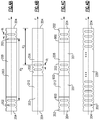
Figure 4C shows a third alternative distribution of grooves or detents along a tube axis Z. -
Figure 4D shows yet another alternative distribution of grooves or detents along a tube axis Z. -
Figure 5A shows an optional feature. -
Figure 5B is a diametric cross-sectional view alongsection 5B-5B fromFigure 5A . -
Figure 5C is another alternative view similar to that ofFigure 5B . -
Figure 6A shows one option in a diametric cross-sectional view -
Figure 6B shows an option associated withFigure 6A . -
Figure 6C shows another option in a diametric cross-sectional view. -
Figure 6D shows an option associated withFigure 6C . -
Figure 6E shows another part of theFigures 6C and 6D option. -
Figure 7A shows one embodiment of an arrangement of grooves or detents along a hoop direction in a representative diametric cross-section. -
Figure 7B shows an alternative feature of an arrangement of grooves or detents along a hoop direction in a representative diametric cross-section. -
Figure 7C shows yet another alternative of an arrangement of grooves or detents along the hoop direction in a representative diametric cross-section. -
Figure 8A shows one potential embodiment of a groove or detent cross-sectional shape. -
Figure 8B shows an alternative embodiment of a groove or detent cross-sectional shape. -
Figure 8C shows yet another alternative embodiment of a groove or detent cross-sectional shape. -
Figure 9A shows a three-dimensional view of a fabrication step. -
Figure 9B shows a diametric cross-sectional view with grooves formed by the fabrication method schematically illustrated inFigure 9A . -
Figure 10A shows an alternative three-dimensional view of a fabrication step. -
Figure 10B shows a diametric cross-sectional view with grooves or detents formed by the fabrication method schematically illustrated inFigure 10A . -
Figure 11 is a flowchart. -
Figure 12A shows a diametric cross-section of the first arrangement. -
Figure 12B shows an axial cross-sectional view of a first step in a method of forming a drive shaft. -
Figure 12C shows a subsequent step. -
Figure 12D shows yet another subsequent step. -
Figure 12E shows yet another subsequent step. -
Figure 13A shows a first heated mold option. -
Figure 13B shows an alternative heated mold option. -
Figure 13C shows yet a third heated mold option. -
Figure 14A show a component which may be formed by the methods disclosed in this application which may be for a use other than a drive shaft. -
Figure 14B shows yet another component which may be formed by the methods of this application. -
Figure 1 shows adrive arrangement 20, which drives acomponent 22 through adrive input 24, and having adrive shaft 26 connecting theinput 24 to theoutput 22. A plurality of grooves ordetents shaft portion 26. Thegrooves drive shaft 26. In fact, thegrooves -
Figure 2A shows a tubular portion 31 of theshaft 26 having the grooves or detents 28 and 30. While grooves are specifically disclosed with regard to the apparatus features of this disclosure,bumps 17 such as mentioned above which extend radially outwardly can be substituted for the grooves in all embodiments. -
Figure 2B is a cross-sectional view through space portions of the repeatedgrooves 28.Figure 2C is a cross-sectional view through thegrooves 30. As can be appreciated fromFigures 2A-2C , groove sets are positioned in general alignment, but spaced axially from each other. Thus, as one can see fromFigures 2A-2C , the circumferential extent of thegrooves 30 extends across a space between ends 19 of spacedgrooves 28. Thegrooves 28 also extend through a space between theends 19 of thegrooves 30. In some embodiments, the ends 19 of thegrooves 30 may extend circumferentially beyond theends 19 of thegrooves 28, and vice versa. In other embodiments, the ends 19 of thegrooves 30 and theends 19 of thegrooves 28 may end before the circumferential location of the other ends 19. - As shown, it could be said the deformations include at least two axially spaced deformation sets, with a first set having deformations between first set circumferential ends and a second set extending between second set circumferential ends. Deformations in the second set extend at least partially into a circumferential space between the first circumferential ends
- As is clear the grooves deform a wall of the preform, but do not cut, or extend, through to an inner surface. As is clear from
Figure 2B , the grooves or detents 28 (although this is also true of thedetents 30, and the other detents to be disclosed below) also deform an innerperipheral surface 13 of the tubular portion 31. Thegroove 28 is showing having an inwardly extendingportion 15 deformed into theinner surface 13. On the other hand, it may be that the deformations need not extend through the entire thickness of the tubular portion 31, and do not deform, say, theinner surface 13. -
Figure 3A shows diametric cross-section with an embodiment of agroove 28 that is relatively flat at anouter surface 29.Figure 3B shows a similar shape to theouter surface 29 of thegroove 30. -
Figure 3C shows diametric cross-section with a more complex shape for agroove 128 on adrive shaft 126. Here,shape 128 has as anoutermost position 129 extending to circumferential ends 131. As is clear, the deformations are formed to have acentral location 129 which extends radially further away from the central axis, and the circumferential ends 131 extend in a circumferential direction toward each other. -
Figure 3D has a similar shape for agroove 130. -
Figure 4A shows a first embodiment wherein there is adrive shaft 200 having aportion 203 in a central location that is generally without grooves. Portions adjacent ends 204 have groove sets 202. There are at least a plurality ofgrooves 202 adjacent theends 204 spaced by a distance d1. The spacing distances d1 can be either the same or variable in the grooved areas. It could be said that a spacing distance d1 between thegrooves 202 at the end portions is greater than a distance d2 between grooves across thenon-groove section 203 having fewer grooves. -
Figure 4B shows adrive shaft embodiment 210 wherein a pair ofnon-groove portions ends 204 of the drive shaft. An area withgrooves 202 is shown at an intermediate location. Here again, a distance d1 between a plurality of grooves in the grooved area is less than a distance between grooves in thenon-grooved areas 210. The distance d2 here is also greater than d1. -
Figure 4C shows a drive shaft 212 having non-grooved areas 201 withend groove portions 900 and acentral groove portion 900. Here again, a distance between a plurality of grooves in each of thegrooved portions 900 is less than a distance between grooves across the portions 201. -
Figure 4D shows a drive shaft 220 wherein thegrooves 202 are formed by uniform or variable spacing across an axial length of the drive shaft and between the axial ends 204. -
Figure 5A shows another potential feature wherein adrive shaft 230 has acentral portion 236 which is relatively small, and endportions 232 havinggrooves 234 such as disclosed above.Portions 232 are either radially larger or/and thicker than thecentral portion 236. - As shown in
Figure 5B , this may be accomplished by either simply having the outer diameter of theportion 234 be larger than the outer diameter of theportion 236 while keeping theinner diameter 998 of theportions portion 234 is greater than a radial thickness t2 of theportion 236. This will provide reinforcement to the area with grooves to mitigate stress concentrations due to the grooves. The groove ordetent 234 is omitted from this view to simplify the section and better illustrate the relative diameters and/or thicknesses. -
Figure 5C shows another embodiment wherein the thickness t1 and t2 of the sections 234' and 236' may be different and theirinner diameters 998' and 998" are also different. It should be understood that theinner diameter 998 between the two sections will change in a linear or non-linear fashion as one moves from the two cross-sections ofFigure 5B . That is, in thesection 999 as shown inFigure 5A , the inner diameter will slope to accommodate the differences between the two sections 234' and 236'. -
Figures 6A and 6B show anembodiment 240 much like that illustrated above with regard toFigure 1 wherein anembodiment 240 much like that illustrated inFigure 1 wherein there are two groove sets 242 and 244. -
Figure 6A shows the first groove set 242 on theshaft 240 wherein thegrooves 242 are centered on theaxis 243. -
Figure 6B shows the second groove set 244 on theshaft 240 wherein thegrooves 244 are centered on anaxis 245. An angle A is defined between theaxes -
Figure 6C shows adrive shaft embodiment 250 having a pair ofgrooves 252 centered on anaxis 254. Inembodiment 250, there are not two axially spaced sets of grooves, but rather three. -
Figure 6D showsgrooves 256 centered onaxis 258. An angle B is defined betweenaxes -
Figure 6E shows another axially spaced cross-section of thedrive shaft 250 wherein there aregrooves 260 centered on anaxis 262.Axis 262 is spaced fromaxis 243 by an angle C. Angle C may be approximately 120°, i.e., approximately twice larger than the angle B. - Embodiments with more than three sets of grooves may be used.
-
Figure 7A shows afirst embodiment shaft 300 wherein there are twogrooves 302 at each axial location in each groove set. -
Figure 7B shows an alternativedrive shaft embodiment 304 wherein there are three circumferentially spacedgrooves 306 in each groove set. -
Figure 7C shows adrive shaft embodiment 308 wherein there are four circumferentially spacedgrooves 310 at each axial location in each groove set. - Of course more than four circumferentially spaced grooves could be used in each axially spaced deformation set.
- The arrangement of grooves circumferentially about a shaft axis Z is similar to the arrangement when only two grooves per the section are used. For example if there are two uniformly positioned grooves shown in
Figure 7A , a diametric complimentary cross-section (Figure 3B ) a rotated at approximately 90°. Similarly in case of three the same, uniformly positioned grooves (Figure 7B ), there is a corresponding cross-section rotated at 60°. In case of four (Figure 7C ), uniformly positioned grooves, there is a similar rotation at 45°, and so on. More complex, but similar mutual arrangements can be defined if there are more than two complimentary sets of grooves, for example of a case shown inFigures 6C-6E for three complimentary sets. -
Figure 8A shows a firstcross-sectional shape 320 for an individual groove presented in an axial cross-section of the shaft (that is, similar to theFigure 2B section).Cross-sectional shape 320 has a generally uniform or non-uniform but concave shape and constant or variable radius R1. -
Figure 8B shows analternative shape 322 wherein there is a centralconcave portion 321 formed about a constant or variable radius R2. There are alsoconvex portions 324 on each side of theportion 321. Theseconvex segments 324 spaced on each end of the concave portion. -
Figure 8C shows anotheralternative groove shape 330 having aflat portion 326,convex end portions 328 at each end of the groove, andconcave portions 327. - A drive shaft could be said to comprise a tubular portion extending between axial ends and being hollow. Deformations are formed from an outer peripheral surface of the cylindrical shaft portion. The deformations extend for a circumferential extent that is less than 180° about a central axis of the tubular portion.
- The shafts as disclosed above may be formed of the same or different fiber-reinforced polymer matrix composite materials. In one embodiment, the matrix can be a thermoplastic polymer. In another embodiment, the matrix can be a thermoset polymer composite. Different types of reinforcing fibers, such as, for example, carbon fibers, glass fibers, organic fibers, inorganic material (e.g. ceramic) fibers, or their combinations can be used in different embodiments. In different embodiments, the same or different fabrication processes, such as for example, automated fiber placement, filament winding, braiding, wrapping, etc. can be used to make separate composite tubes and diaphragms. Alternatively, this disclosure would also extend to metal shafts.
- A method of forming such shafts is now disclosed.
-
Figure 9A shows a tubular portion formed of a thermoplastic shaft preform.Heated molds 402 are brought into contact with compression against thetubular preform 400 to form thegrooves 404. Although heated molds are disclosed, with certain materials the molds need not be heated. As an example if a thermoplastic is used heated molds may be used. The molds need not be heated when a thermoset or metal is used. As an example, a mold may be brought into contact with a partially curved thermoset polymer composite preform shaft. - As shown in this embodiment, the molds are generally cylindrical. However, in particular and as an example only, the several shapes of the grooves or detents, as disclosed above, could inform the shape of the molds.
-
Figure 9B shows diametric cross-sectional view of ashaft 406 having thegrooves 408 formed to be generally flat and extending between circumferentially spaced curved ends 409. This embodiment would be similar to that illustrated inFigures 3A and 3B . -
Figure 10A shows ashaft preform 420 receivingmolds 424, which have a curvature to them, and which form thegroove areas 422. - As shown in
Figure 10B for a diametric cross-sectional view of ashaft 420, thegrooves 430 on the formedshaft 428 extend between cylindrical ends 434. This embodiment would be similar to that illustrated inFigures 3C and 3D . -
Figure 11 is a flowchart of the methods as disclosed. - In an initial step, molds are heated at
step 500. Those molds are brought into contact with external surfaces of a shaft preform atstep 502. - Compression is applied to the mold or molds at
step 504. - Upon specified deformation being achieved, the molds are removed at
step 506. - Portions of the mold may be rotated and/or moved axially to a new position at
step 508. The method then returns to step 502 and is repeated as many times as necessary atstep 510. -
Figure 12A shows optional additional details of a mold embodiment as a diametric cross-sectional view. Themolds 524 are the external heated molds such as described above. While generally cylindrical and straight molds are illustrated here, the methods to be described would also apply to the more curved molds such as shown inFigure 10A . - The
shaft preform 520 receives aninternal molding support 522.Support 522 has radially outer extendingportions 525 withintermediate spaces 523. - In a step illustrated in
Figure 12B as an axial cross-sectional view, theportions 525 are axially and circumferentially aligned with an area where it is desirable to form the grooves from theheated molds 524. As can be appreciated in this view, theinternal support 522 actually has spacedparts internal faces 527 to deform aninternal space 529. A control for the mold would move theinternal support 522 such thatspace 529 is axially aligned with themolds 524. - As shown in the step of
Figure 12C as an axial cross-sectional view, compression is then applied to theheated mold portions 524 andgrooves shaft preform 520, with the molds deforming the preform intogrooves -
Figure 12D shows an axial cross-sectional view of a subsequent step. After thegrooves internal support 522 may be rotated circumferentially such that the spaces orareas 523 are now aligned with thegrooves Figure 12E , and such that theportions 525 now extend into and out of the plane ofFigure 12E .Molds 524 can be moved or arranged to be aligned circumferentially with the location of theenlarged portions 525 such that a second group of grooves can be formed. - As an example and returning to
Figure 1 , method step 12C may form, say the groove pairs 28, whereas method 12E may form the groove pairs 30. Of course, if more than two sets of grooves are formed, more than two steps and rotations will be utilized. - A
motor 600 is shown schematically to rotate and move thesupport 522 axially. Alternatively, the preform could be moved. An appropriate control can operate to control thesupport 522 and the heated molds in cooperation to form the grooves. -
Figures 13A-13C show diametric cross-sectional views.Figure 13A shows a method embodiment wherein there are twoheated molds 700 spaced about atubular preform 701. -
Figure 13B shows an embodiment wherein there are threeheated molds 702 spaced circumferentially about apreform 701. -
Figure 13C shows an embodiment wherein there are fourheated molds 703 spaced about apreform 701. It should be understood that the embodiments ofFigures 13A, 13B, or 13C may also form a groove which extends about the entire 360° in the circumferential direction if needed. -
Figures 14A and 14B show axial cross-sectional views.Figure 14A shows anon-cylindrical component 710 which may be made with the methods as described above. Grooves are formed into anouter surface 711 byheated molds 712 in a manner similar to that disclosed above. Thecomponent 710 could be any number of aerospace components, or could be components for other applications. -
Figure 14B shows anon-cylindrical component 714 with curved segments.Heated molds peripheral surface 715, again according to methods as described above. - A drive shaft could be said to include a tubular portion extending between axial ends and being hollow. There are
deformations 28/30/17 extending from an outer peripheral surface of the cylindrical shaft portion. The deformations extend for a circumferential extent that is less than 180° about a central axis of the tubular portion. Deformations in one of the axially spaced extents extend between first circumferential ends and deformations in a second of the axially spaced groove sets extend between second circumferential ends and the deformations in the second axially spaced sets extend at least partially in a circumferential space between the first circumferential ends. - Methods, such as disclosed above, are claimed in co-pending United States Patent Application Serial No.
16/247928 - Although an embodiment of this invention has been disclosed, a worker of ordinary skill in this art would recognize that certain modifications would come within the scope of this disclosure. For that reason, the following claims should be studied to determine the true scope and content of this disclosure.
Claims (15)
- A drive shaft (26) comprising:
a tubular portion (31) extending between axial ends and being hollow, and there being deformations on the tubular portions (31), said deformations extending for a circumferential extent that is less than 180° about a central axis of said tubular portion (31). - The drive shaft of claim 1, wherein said deformations are detents.
- The drive shaft as set forth in claim 1, wherein said deformations include at least two axially spaced deformation sets, with a first of said axially spaced deformation sets having deformations extending between first set circumferential ends and said deformations in a second of said axially spaced deformation sets extending between second set circumferential ends and said deformations in said second axially spaced deformation sets extend at least partially in a circumferential space between said first circumferential ends.
- The drive shaft as set forth in claim 3, wherein there are two circumferentially spaced ones of said deformations in each of said axially spaced deformation sets, and preferably wherein there are three or more circumferentially spaced deformations in each of said axially spaced sets.
- The drive shaft as set forth in claim 3, wherein there are at least three of said axially spaced deformation sets having deformations extending through a common circumferential extent.
- The drive shaft as set forth in claim 1, wherein said deformations are formed to be generally tangent to a radius from said central axis.
- The drive shaft as set forth in claim 1, wherein said deformations are formed to have a central location which extends radially further away from said central axis.
- The drive shaft as set forth in claim 1, wherein said deformations are spaced by a first distance across an axial length of said tubular portion (31) between said first and second ends.
- The drive shaft as set forth in claim 1, wherein there are first deformation sets in at least one axial location between said axial ends of said tubular portion (31), with a plurality of deformations spaced by a first distance.
- The drive shaft as set forth in claim 9, wherein there is at least one lesser deformation portion wherein said deformations are spaced by a distance greater than said first axial distance.
- The drive shaft as set forth in claim 9, wherein said first deformation sets are formed in a thicker portion, and said at least one lesser deformation portion is formed at a thinner portion.
- The drive shaft as set forth in claim 11, wherein said thicker portion has a greater radius to an outer peripheral surface than does said thinner portion; or
wherein said thinner portion has a first wall thickness to a hollow interior and said thicker portion has a second wall thickness and said second wall thickness is greater than said first wall thickness. - The drive shaft as set forth in claim 1, wherein there are axially spaced deformation sets and there are at least two circumferentially spaced deformations in each of said axially spaced deformation sets, and preferably wherein there are at least three of said deformations in each of said axially spaced deformation sets.
- The drive shaft as set forth in claim 1, wherein said deformations are detents with a generally concave shape formed about a single radius in a cross-section taken through a diameter of said tubular portion, and preferably
wherein said detents have a generally concave shape through a plane taken through a diameter of said tubular portion (31), and wherein there are convex segments spaced on each end of said concave portion. - The drive shaft as set forth in claim 1, wherein said deformations are detents having a generally linear surface in a plane taken through a diameter of said tubular portion with shapes at each axial end of said generally linear portion which are at least one of convex and concave shapes; or
wherein said deformations extend radially outwardly of said outer peripheral surface.
Applications Claiming Priority (1)
| Application Number | Priority Date | Filing Date | Title |
|---|---|---|---|
| US16/247,856 US12253107B2 (en) | 2019-01-15 | 2019-01-15 | Drive shafts with enhanced bending flexibility |
Publications (2)
| Publication Number | Publication Date |
|---|---|
| EP3683461A1 true EP3683461A1 (en) | 2020-07-22 |
| EP3683461B1 EP3683461B1 (en) | 2022-04-06 |
Family
ID=68470436
Family Applications (1)
| Application Number | Title | Priority Date | Filing Date |
|---|---|---|---|
| EP19207528.1A Active EP3683461B1 (en) | 2019-01-15 | 2019-11-06 | Drive shafts with enhanced bending flexibility |
Country Status (2)
| Country | Link |
|---|---|
| US (1) | US12253107B2 (en) |
| EP (1) | EP3683461B1 (en) |
Cited By (1)
| Publication number | Priority date | Publication date | Assignee | Title |
|---|---|---|---|---|
| EP3809003A1 (en) * | 2019-10-17 | 2021-04-21 | Hamilton Sundstrand Corporation | Drive shafts made of composite materials and methods of making such shafts |
Citations (6)
| Publication number | Priority date | Publication date | Assignee | Title |
|---|---|---|---|---|
| FR2660713A1 (en) * | 1990-04-04 | 1991-10-11 | Gkn Automotive Ag | DRIVE SHAFT. |
| US5429574A (en) * | 1991-04-09 | 1995-07-04 | Murakami; Yukiyoshi | Shaft member for business machines and the like and its manufacturing method |
| FR2755042A1 (en) * | 1996-10-24 | 1998-04-30 | Lemforder Nacam Sa | PROCESS FOR OBTAINING SPLINES ON A TREE |
| US20140137700A1 (en) * | 2011-06-22 | 2014-05-22 | Mt Aerospace Ag | Component for absorbing and/or transmitting mechanical forces and/or moments, method for producing same and use thereof |
| WO2014127352A1 (en) * | 2013-02-18 | 2014-08-21 | Szuba Consulting, Inc. | Collapsible shaft assembly with flanged slots |
| US20160247928A1 (en) | 2015-02-20 | 2016-08-25 | Semiconductor Energy Laboratory Co., Ltd. | Semiconductor device and fabrication method thereof |
Family Cites Families (11)
| Publication number | Priority date | Publication date | Assignee | Title |
|---|---|---|---|---|
| US4173128A (en) | 1978-05-23 | 1979-11-06 | Grumman Aerospace Corporation | Composite drive shaft |
| US4330142A (en) * | 1980-01-10 | 1982-05-18 | Fayette Tubular Products | Formed hose couplings |
| IT231394Y1 (en) * | 1993-05-21 | 1999-08-03 | Italiana Serrature Torino | FLEXIBLE HOSE WITH TEMPERATURE AND / OR PRESSURE TIGHTNESS FEATURES |
| US6015350A (en) * | 1997-12-03 | 2000-01-18 | Dana Corporation | Collapsible vehicle driveshaft |
| SE517177C2 (en) | 2000-03-09 | 2002-04-23 | Volvo Lastvagnar Ab | Shaft coupling |
| MXPA06007158A (en) * | 2005-06-30 | 2007-01-19 | Schlumberger Technology Bv | Coiled tubing dimple connection. |
| WO2007083491A1 (en) * | 2006-01-19 | 2007-07-26 | Ntn Corporation | Shaft member for dynamic pressure bearing device |
| US7878911B2 (en) * | 2007-11-09 | 2011-02-01 | GM Global Technology Operations LLC | Fluid transfer tube |
| US9458958B2 (en) * | 2009-03-03 | 2016-10-04 | Neoperl Gmbh | Hose coupling |
| US20120283029A1 (en) | 2009-12-29 | 2012-11-08 | Lawrie Duncan J | High torque density flexible composite driveshaft |
| US9909624B2 (en) | 2015-09-22 | 2018-03-06 | Rohr, Inc. | Composite driveshaft for a rotary system |
-
2019
- 2019-01-15 US US16/247,856 patent/US12253107B2/en active Active
- 2019-11-06 EP EP19207528.1A patent/EP3683461B1/en active Active
Patent Citations (6)
| Publication number | Priority date | Publication date | Assignee | Title |
|---|---|---|---|---|
| FR2660713A1 (en) * | 1990-04-04 | 1991-10-11 | Gkn Automotive Ag | DRIVE SHAFT. |
| US5429574A (en) * | 1991-04-09 | 1995-07-04 | Murakami; Yukiyoshi | Shaft member for business machines and the like and its manufacturing method |
| FR2755042A1 (en) * | 1996-10-24 | 1998-04-30 | Lemforder Nacam Sa | PROCESS FOR OBTAINING SPLINES ON A TREE |
| US20140137700A1 (en) * | 2011-06-22 | 2014-05-22 | Mt Aerospace Ag | Component for absorbing and/or transmitting mechanical forces and/or moments, method for producing same and use thereof |
| WO2014127352A1 (en) * | 2013-02-18 | 2014-08-21 | Szuba Consulting, Inc. | Collapsible shaft assembly with flanged slots |
| US20160247928A1 (en) | 2015-02-20 | 2016-08-25 | Semiconductor Energy Laboratory Co., Ltd. | Semiconductor device and fabrication method thereof |
Cited By (2)
| Publication number | Priority date | Publication date | Assignee | Title |
|---|---|---|---|---|
| EP3809003A1 (en) * | 2019-10-17 | 2021-04-21 | Hamilton Sundstrand Corporation | Drive shafts made of composite materials and methods of making such shafts |
| US11859665B2 (en) | 2019-10-17 | 2024-01-02 | Hamilton Sundstrand Corporation | Drive shafts made of composite materials and methods of making such shafts |
Also Published As
| Publication number | Publication date |
|---|---|
| US20200224710A1 (en) | 2020-07-16 |
| US12253107B2 (en) | 2025-03-18 |
| EP3683461B1 (en) | 2022-04-06 |
Similar Documents
| Publication | Publication Date | Title |
|---|---|---|
| RU2541032C2 (en) | Method of making composite connecting link and connecting link made using said method | |
| EP3194093B1 (en) | Method of manufacturing a hollow rack bar | |
| TWI862676B (en) | Method for producing a positive-locking load application for tension-compression rod, and tension-compression rod | |
| EP3295047B1 (en) | Fibre reinforced polymer matrix composite torque tubes or shafts | |
| EP3683037B1 (en) | Methods of making components | |
| EP3854572B1 (en) | Flexible thermoplastic composite coupling and method of manufacture | |
| KR101509103B1 (en) | Composite pipe, composite roller, composite pipe manufacturing method and composite roller manufacturing method using the composite pipe | |
| US12320387B2 (en) | Drive shaft with non-cylindrical shape | |
| EP3683461B1 (en) | Drive shafts with enhanced bending flexibility | |
| EP3711932B1 (en) | Manufacturing methods for composite driveshafts | |
| US12305704B2 (en) | Method for manufacturing by molding elongate and hollow workpieces made from composite material, molding device for implementing the method and workpieces obtained | |
| JP5297801B2 (en) | Applicable blade | |
| EP3594515B1 (en) | Linear guide and process to produce such a linear guide | |
| US20240369096A1 (en) | Integrated composite drive shafts | |
| EP4345325B1 (en) | Drive shaft with non-cylindrical shape and spaced reinforcements | |
| JP2023136190A (en) | Method for manufacturing mandrel and fiber-reinforced resin tube body | |
| EP4438914A1 (en) | Integrated composite drive shafts | |
| US9869341B2 (en) | Internally grooved components | |
| JPH03281232A (en) | Mandrel for molding tubular body having different diameter part on inner surface thereof and molding method using the same |
Legal Events
| Date | Code | Title | Description |
|---|---|---|---|
| PUAI | Public reference made under article 153(3) epc to a published international application that has entered the european phase |
Free format text: ORIGINAL CODE: 0009012 |
|
| STAA | Information on the status of an ep patent application or granted ep patent |
Free format text: STATUS: THE APPLICATION HAS BEEN PUBLISHED |
|
| AK | Designated contracting states |
Kind code of ref document: A1 Designated state(s): AL AT BE BG CH CY CZ DE DK EE ES FI FR GB GR HR HU IE IS IT LI LT LU LV MC MK MT NL NO PL PT RO RS SE SI SK SM TR |
|
| AX | Request for extension of the european patent |
Extension state: BA ME |
|
| STAA | Information on the status of an ep patent application or granted ep patent |
Free format text: STATUS: REQUEST FOR EXAMINATION WAS MADE |
|
| 17P | Request for examination filed |
Effective date: 20210119 |
|
| RBV | Designated contracting states (corrected) |
Designated state(s): AL AT BE BG CH CY CZ DE DK EE ES FI FR GB GR HR HU IE IS IT LI LT LU LV MC MK MT NL NO PL PT RO RS SE SI SK SM TR |
|
| STAA | Information on the status of an ep patent application or granted ep patent |
Free format text: STATUS: EXAMINATION IS IN PROGRESS |
|
| 17Q | First examination report despatched |
Effective date: 20210224 |
|
| GRAP | Despatch of communication of intention to grant a patent |
Free format text: ORIGINAL CODE: EPIDOSNIGR1 |
|
| STAA | Information on the status of an ep patent application or granted ep patent |
Free format text: STATUS: GRANT OF PATENT IS INTENDED |
|
| INTG | Intention to grant announced |
Effective date: 20211115 |
|
| GRAS | Grant fee paid |
Free format text: ORIGINAL CODE: EPIDOSNIGR3 |
|
| GRAA | (expected) grant |
Free format text: ORIGINAL CODE: 0009210 |
|
| STAA | Information on the status of an ep patent application or granted ep patent |
Free format text: STATUS: THE PATENT HAS BEEN GRANTED |
|
| AK | Designated contracting states |
Kind code of ref document: B1 Designated state(s): AL AT BE BG CH CY CZ DE DK EE ES FI FR GB GR HR HU IE IS IT LI LT LU LV MC MK MT NL NO PL PT RO RS SE SI SK SM TR |
|
| REG | Reference to a national code |
Ref country code: GB Ref legal event code: FG4D |
|
| REG | Reference to a national code |
Ref country code: CH Ref legal event code: EP |
|
| REG | Reference to a national code |
Ref country code: AT Ref legal event code: REF Ref document number: 1481606 Country of ref document: AT Kind code of ref document: T Effective date: 20220415 |
|
| REG | Reference to a national code |
Ref country code: IE Ref legal event code: FG4D |
|
| REG | Reference to a national code |
Ref country code: DE Ref legal event code: R096 Ref document number: 602019013358 Country of ref document: DE |
|
| REG | Reference to a national code |
Ref country code: LT Ref legal event code: MG9D |
|
| REG | Reference to a national code |
Ref country code: NL Ref legal event code: MP Effective date: 20220406 |
|
| REG | Reference to a national code |
Ref country code: AT Ref legal event code: MK05 Ref document number: 1481606 Country of ref document: AT Kind code of ref document: T Effective date: 20220406 |
|
| PG25 | Lapsed in a contracting state [announced via postgrant information from national office to epo] |
Ref country code: NL Free format text: LAPSE BECAUSE OF FAILURE TO SUBMIT A TRANSLATION OF THE DESCRIPTION OR TO PAY THE FEE WITHIN THE PRESCRIBED TIME-LIMIT Effective date: 20220406 |
|
| PG25 | Lapsed in a contracting state [announced via postgrant information from national office to epo] |
Ref country code: SE Free format text: LAPSE BECAUSE OF FAILURE TO SUBMIT A TRANSLATION OF THE DESCRIPTION OR TO PAY THE FEE WITHIN THE PRESCRIBED TIME-LIMIT Effective date: 20220406 Ref country code: PT Free format text: LAPSE BECAUSE OF FAILURE TO SUBMIT A TRANSLATION OF THE DESCRIPTION OR TO PAY THE FEE WITHIN THE PRESCRIBED TIME-LIMIT Effective date: 20220808 Ref country code: NO Free format text: LAPSE BECAUSE OF FAILURE TO SUBMIT A TRANSLATION OF THE DESCRIPTION OR TO PAY THE FEE WITHIN THE PRESCRIBED TIME-LIMIT Effective date: 20220706 Ref country code: LT Free format text: LAPSE BECAUSE OF FAILURE TO SUBMIT A TRANSLATION OF THE DESCRIPTION OR TO PAY THE FEE WITHIN THE PRESCRIBED TIME-LIMIT Effective date: 20220406 Ref country code: HR Free format text: LAPSE BECAUSE OF FAILURE TO SUBMIT A TRANSLATION OF THE DESCRIPTION OR TO PAY THE FEE WITHIN THE PRESCRIBED TIME-LIMIT Effective date: 20220406 Ref country code: GR Free format text: LAPSE BECAUSE OF FAILURE TO SUBMIT A TRANSLATION OF THE DESCRIPTION OR TO PAY THE FEE WITHIN THE PRESCRIBED TIME-LIMIT Effective date: 20220707 Ref country code: FI Free format text: LAPSE BECAUSE OF FAILURE TO SUBMIT A TRANSLATION OF THE DESCRIPTION OR TO PAY THE FEE WITHIN THE PRESCRIBED TIME-LIMIT Effective date: 20220406 Ref country code: ES Free format text: LAPSE BECAUSE OF FAILURE TO SUBMIT A TRANSLATION OF THE DESCRIPTION OR TO PAY THE FEE WITHIN THE PRESCRIBED TIME-LIMIT Effective date: 20220406 Ref country code: BG Free format text: LAPSE BECAUSE OF FAILURE TO SUBMIT A TRANSLATION OF THE DESCRIPTION OR TO PAY THE FEE WITHIN THE PRESCRIBED TIME-LIMIT Effective date: 20220706 Ref country code: AT Free format text: LAPSE BECAUSE OF FAILURE TO SUBMIT A TRANSLATION OF THE DESCRIPTION OR TO PAY THE FEE WITHIN THE PRESCRIBED TIME-LIMIT Effective date: 20220406 |
|
| PG25 | Lapsed in a contracting state [announced via postgrant information from national office to epo] |
Ref country code: RS Free format text: LAPSE BECAUSE OF FAILURE TO SUBMIT A TRANSLATION OF THE DESCRIPTION OR TO PAY THE FEE WITHIN THE PRESCRIBED TIME-LIMIT Effective date: 20220406 Ref country code: PL Free format text: LAPSE BECAUSE OF FAILURE TO SUBMIT A TRANSLATION OF THE DESCRIPTION OR TO PAY THE FEE WITHIN THE PRESCRIBED TIME-LIMIT Effective date: 20220406 Ref country code: LV Free format text: LAPSE BECAUSE OF FAILURE TO SUBMIT A TRANSLATION OF THE DESCRIPTION OR TO PAY THE FEE WITHIN THE PRESCRIBED TIME-LIMIT Effective date: 20220406 Ref country code: IS Free format text: LAPSE BECAUSE OF FAILURE TO SUBMIT A TRANSLATION OF THE DESCRIPTION OR TO PAY THE FEE WITHIN THE PRESCRIBED TIME-LIMIT Effective date: 20220806 |
|
| REG | Reference to a national code |
Ref country code: DE Ref legal event code: R097 Ref document number: 602019013358 Country of ref document: DE |
|
| PG25 | Lapsed in a contracting state [announced via postgrant information from national office to epo] |
Ref country code: SM Free format text: LAPSE BECAUSE OF FAILURE TO SUBMIT A TRANSLATION OF THE DESCRIPTION OR TO PAY THE FEE WITHIN THE PRESCRIBED TIME-LIMIT Effective date: 20220406 Ref country code: SK Free format text: LAPSE BECAUSE OF FAILURE TO SUBMIT A TRANSLATION OF THE DESCRIPTION OR TO PAY THE FEE WITHIN THE PRESCRIBED TIME-LIMIT Effective date: 20220406 Ref country code: RO Free format text: LAPSE BECAUSE OF FAILURE TO SUBMIT A TRANSLATION OF THE DESCRIPTION OR TO PAY THE FEE WITHIN THE PRESCRIBED TIME-LIMIT Effective date: 20220406 Ref country code: EE Free format text: LAPSE BECAUSE OF FAILURE TO SUBMIT A TRANSLATION OF THE DESCRIPTION OR TO PAY THE FEE WITHIN THE PRESCRIBED TIME-LIMIT Effective date: 20220406 Ref country code: DK Free format text: LAPSE BECAUSE OF FAILURE TO SUBMIT A TRANSLATION OF THE DESCRIPTION OR TO PAY THE FEE WITHIN THE PRESCRIBED TIME-LIMIT Effective date: 20220406 Ref country code: CZ Free format text: LAPSE BECAUSE OF FAILURE TO SUBMIT A TRANSLATION OF THE DESCRIPTION OR TO PAY THE FEE WITHIN THE PRESCRIBED TIME-LIMIT Effective date: 20220406 |
|
| PLBE | No opposition filed within time limit |
Free format text: ORIGINAL CODE: 0009261 |
|
| STAA | Information on the status of an ep patent application or granted ep patent |
Free format text: STATUS: NO OPPOSITION FILED WITHIN TIME LIMIT |
|
| 26N | No opposition filed |
Effective date: 20230110 |
|
| PG25 | Lapsed in a contracting state [announced via postgrant information from national office to epo] |
Ref country code: AL Free format text: LAPSE BECAUSE OF FAILURE TO SUBMIT A TRANSLATION OF THE DESCRIPTION OR TO PAY THE FEE WITHIN THE PRESCRIBED TIME-LIMIT Effective date: 20220406 |
|
| PG25 | Lapsed in a contracting state [announced via postgrant information from national office to epo] |
Ref country code: SI Free format text: LAPSE BECAUSE OF FAILURE TO SUBMIT A TRANSLATION OF THE DESCRIPTION OR TO PAY THE FEE WITHIN THE PRESCRIBED TIME-LIMIT Effective date: 20220406 |
|
| PG25 | Lapsed in a contracting state [announced via postgrant information from national office to epo] |
Ref country code: MC Free format text: LAPSE BECAUSE OF FAILURE TO SUBMIT A TRANSLATION OF THE DESCRIPTION OR TO PAY THE FEE WITHIN THE PRESCRIBED TIME-LIMIT Effective date: 20220406 |
|
| REG | Reference to a national code |
Ref country code: CH Ref legal event code: PL |
|
| P01 | Opt-out of the competence of the unified patent court (upc) registered |
Effective date: 20230603 |
|
| REG | Reference to a national code |
Ref country code: BE Ref legal event code: MM Effective date: 20221130 |
|
| PG25 | Lapsed in a contracting state [announced via postgrant information from national office to epo] |
Ref country code: LI Free format text: LAPSE BECAUSE OF NON-PAYMENT OF DUE FEES Effective date: 20221130 Ref country code: CH Free format text: LAPSE BECAUSE OF NON-PAYMENT OF DUE FEES Effective date: 20221130 |
|
| PG25 | Lapsed in a contracting state [announced via postgrant information from national office to epo] |
Ref country code: LU Free format text: LAPSE BECAUSE OF NON-PAYMENT OF DUE FEES Effective date: 20221106 |
|
| PG25 | Lapsed in a contracting state [announced via postgrant information from national office to epo] |
Ref country code: IE Free format text: LAPSE BECAUSE OF NON-PAYMENT OF DUE FEES Effective date: 20221106 |
|
| PG25 | Lapsed in a contracting state [announced via postgrant information from national office to epo] |
Ref country code: BE Free format text: LAPSE BECAUSE OF NON-PAYMENT OF DUE FEES Effective date: 20221130 |
|
| PG25 | Lapsed in a contracting state [announced via postgrant information from national office to epo] |
Ref country code: IT Free format text: LAPSE BECAUSE OF FAILURE TO SUBMIT A TRANSLATION OF THE DESCRIPTION OR TO PAY THE FEE WITHIN THE PRESCRIBED TIME-LIMIT Effective date: 20220406 |
|
| PG25 | Lapsed in a contracting state [announced via postgrant information from national office to epo] |
Ref country code: HU Free format text: LAPSE BECAUSE OF FAILURE TO SUBMIT A TRANSLATION OF THE DESCRIPTION OR TO PAY THE FEE WITHIN THE PRESCRIBED TIME-LIMIT; INVALID AB INITIO Effective date: 20191106 |
|
| PG25 | Lapsed in a contracting state [announced via postgrant information from national office to epo] |
Ref country code: CY Free format text: LAPSE BECAUSE OF FAILURE TO SUBMIT A TRANSLATION OF THE DESCRIPTION OR TO PAY THE FEE WITHIN THE PRESCRIBED TIME-LIMIT Effective date: 20220406 |
|
| PG25 | Lapsed in a contracting state [announced via postgrant information from national office to epo] |
Ref country code: MK Free format text: LAPSE BECAUSE OF FAILURE TO SUBMIT A TRANSLATION OF THE DESCRIPTION OR TO PAY THE FEE WITHIN THE PRESCRIBED TIME-LIMIT Effective date: 20220406 |
|
| PG25 | Lapsed in a contracting state [announced via postgrant information from national office to epo] |
Ref country code: TR Free format text: LAPSE BECAUSE OF FAILURE TO SUBMIT A TRANSLATION OF THE DESCRIPTION OR TO PAY THE FEE WITHIN THE PRESCRIBED TIME-LIMIT Effective date: 20220406 |
|
| PG25 | Lapsed in a contracting state [announced via postgrant information from national office to epo] |
Ref country code: MT Free format text: LAPSE BECAUSE OF FAILURE TO SUBMIT A TRANSLATION OF THE DESCRIPTION OR TO PAY THE FEE WITHIN THE PRESCRIBED TIME-LIMIT Effective date: 20220406 |
|
| PG25 | Lapsed in a contracting state [announced via postgrant information from national office to epo] |
Ref country code: BG Free format text: LAPSE BECAUSE OF FAILURE TO SUBMIT A TRANSLATION OF THE DESCRIPTION OR TO PAY THE FEE WITHIN THE PRESCRIBED TIME-LIMIT Effective date: 20220406 |
|
| PG25 | Lapsed in a contracting state [announced via postgrant information from national office to epo] |
Ref country code: BG Free format text: LAPSE BECAUSE OF FAILURE TO SUBMIT A TRANSLATION OF THE DESCRIPTION OR TO PAY THE FEE WITHIN THE PRESCRIBED TIME-LIMIT Effective date: 20220406 |
|
| PGFP | Annual fee paid to national office [announced via postgrant information from national office to epo] |
Ref country code: DE Payment date: 20251022 Year of fee payment: 7 |
|
| PGFP | Annual fee paid to national office [announced via postgrant information from national office to epo] |
Ref country code: GB Payment date: 20251023 Year of fee payment: 7 |
|
| PGFP | Annual fee paid to national office [announced via postgrant information from national office to epo] |
Ref country code: FR Payment date: 20251023 Year of fee payment: 7 |