EP3683446A1 - Ducted fan assembly with curved stators - Google Patents
Ducted fan assembly with curved stators Download PDFInfo
- Publication number
- EP3683446A1 EP3683446A1 EP20151927.9A EP20151927A EP3683446A1 EP 3683446 A1 EP3683446 A1 EP 3683446A1 EP 20151927 A EP20151927 A EP 20151927A EP 3683446 A1 EP3683446 A1 EP 3683446A1
- Authority
- EP
- European Patent Office
- Prior art keywords
- stator
- coupled
- wall
- hub
- fan
- Prior art date
- Legal status (The legal status is an assumption and is not a legal conclusion. Google has not performed a legal analysis and makes no representation as to the accuracy of the status listed.)
- Granted
Links
Images


Classifications
-
- B—PERFORMING OPERATIONS; TRANSPORTING
- B64—AIRCRAFT; AVIATION; COSMONAUTICS
- B64C—AEROPLANES; HELICOPTERS
- B64C11/00—Propellers, e.g. of ducted type; Features common to propellers and rotors for rotorcraft
- B64C11/001—Shrouded propellers
-
- F—MECHANICAL ENGINEERING; LIGHTING; HEATING; WEAPONS; BLASTING
- F04—POSITIVE - DISPLACEMENT MACHINES FOR LIQUIDS; PUMPS FOR LIQUIDS OR ELASTIC FLUIDS
- F04D—NON-POSITIVE-DISPLACEMENT PUMPS
- F04D29/00—Details, component parts, or accessories
- F04D29/40—Casings; Connections of working fluid
- F04D29/52—Casings; Connections of working fluid for axial pumps
- F04D29/54—Fluid-guiding means, e.g. diffusers
- F04D29/541—Specially adapted for elastic fluid pumps
- F04D29/545—Ducts
-
- B—PERFORMING OPERATIONS; TRANSPORTING
- B64—AIRCRAFT; AVIATION; COSMONAUTICS
- B64C—AEROPLANES; HELICOPTERS
- B64C11/00—Propellers, e.g. of ducted type; Features common to propellers and rotors for rotorcraft
- B64C11/46—Arrangements of, or constructional features peculiar to, multiple propellers
-
- B—PERFORMING OPERATIONS; TRANSPORTING
- B64—AIRCRAFT; AVIATION; COSMONAUTICS
- B64C—AEROPLANES; HELICOPTERS
- B64C29/00—Aircraft capable of landing or taking-off vertically, e.g. vertical take-off and landing [VTOL] aircraft
- B64C29/0008—Aircraft capable of landing or taking-off vertically, e.g. vertical take-off and landing [VTOL] aircraft having its flight directional axis horizontal when grounded
- B64C29/0016—Aircraft capable of landing or taking-off vertically, e.g. vertical take-off and landing [VTOL] aircraft having its flight directional axis horizontal when grounded the lift during taking-off being created by free or ducted propellers or by blowers
- B64C29/0033—Aircraft capable of landing or taking-off vertically, e.g. vertical take-off and landing [VTOL] aircraft having its flight directional axis horizontal when grounded the lift during taking-off being created by free or ducted propellers or by blowers the propellers being tiltable relative to the fuselage
-
- F—MECHANICAL ENGINEERING; LIGHTING; HEATING; WEAPONS; BLASTING
- F04—POSITIVE - DISPLACEMENT MACHINES FOR LIQUIDS; PUMPS FOR LIQUIDS OR ELASTIC FLUIDS
- F04D—NON-POSITIVE-DISPLACEMENT PUMPS
- F04D19/00—Axial-flow pumps
-
- F—MECHANICAL ENGINEERING; LIGHTING; HEATING; WEAPONS; BLASTING
- F04—POSITIVE - DISPLACEMENT MACHINES FOR LIQUIDS; PUMPS FOR LIQUIDS OR ELASTIC FLUIDS
- F04D—NON-POSITIVE-DISPLACEMENT PUMPS
- F04D29/00—Details, component parts, or accessories
- F04D29/40—Casings; Connections of working fluid
- F04D29/52—Casings; Connections of working fluid for axial pumps
- F04D29/54—Fluid-guiding means, e.g. diffusers
- F04D29/541—Specially adapted for elastic fluid pumps
- F04D29/542—Bladed diffusers
-
- F—MECHANICAL ENGINEERING; LIGHTING; HEATING; WEAPONS; BLASTING
- F04—POSITIVE - DISPLACEMENT MACHINES FOR LIQUIDS; PUMPS FOR LIQUIDS OR ELASTIC FLUIDS
- F04D—NON-POSITIVE-DISPLACEMENT PUMPS
- F04D29/00—Details, component parts, or accessories
- F04D29/40—Casings; Connections of working fluid
- F04D29/52—Casings; Connections of working fluid for axial pumps
- F04D29/54—Fluid-guiding means, e.g. diffusers
- F04D29/541—Specially adapted for elastic fluid pumps
- F04D29/542—Bladed diffusers
- F04D29/544—Blade shapes
-
- F—MECHANICAL ENGINEERING; LIGHTING; HEATING; WEAPONS; BLASTING
- F04—POSITIVE - DISPLACEMENT MACHINES FOR LIQUIDS; PUMPS FOR LIQUIDS OR ELASTIC FLUIDS
- F04D—NON-POSITIVE-DISPLACEMENT PUMPS
- F04D19/00—Axial-flow pumps
- F04D19/002—Axial flow fans
-
- F—MECHANICAL ENGINEERING; LIGHTING; HEATING; WEAPONS; BLASTING
- F05—INDEXING SCHEMES RELATING TO ENGINES OR PUMPS IN VARIOUS SUBCLASSES OF CLASSES F01-F04
- F05D—INDEXING SCHEME FOR ASPECTS RELATING TO NON-POSITIVE-DISPLACEMENT MACHINES OR ENGINES, GAS-TURBINES OR JET-PROPULSION PLANTS
- F05D2250/00—Geometry
- F05D2250/70—Shape
- F05D2250/71—Shape curved
Definitions
- a ducted fan is a propulsive apparatus in which a plurality of propulsive fan blades are disposed within a duct.
- Multiple vehicles use ducted fans to generate propulsion and perform a multitude of functions. Such functions include generating forward thrust, generating lift, and generating antitorque.
- air and sea vehicles like the Bell X-22 and the Landing Craft Air Cushion (LCAC), respectively, use ducted fans to generate forward thrust.
- LCAC Landing Craft Air Cushion
- VTOL vertical take off and landing
- helicopter models use ducted fans, in some cases in the form of fenestrons, to generate antitorque and yaw moments during operations.
- Conventional ducted fans generally comprise a duct that houses a mechanical fan at its center. During operations, the mechanical fan generates a propulsive force by using a power source to spin a plurality of propulsive fan blades. Because the mechanical fan functions within the confines of the duct, the mechanical fan must be secured in place to prevent the fan blades from striking the walls of the duct.
- Conventional ducted fans use stators to provide structural support to the mechanical fan and hold it in place relative to the duct.
- Conventional stators are generally straight, long, narrow, and fixed at their ends to both the mechanical fan and the duct.
- Conventional stators tend to be radially oriented about the center of the duct but can alternatively be radially offset.
- the conventional stators are disposed behind the fan blades and are usually aerodynamically shaped to allow easy passage of the airflow generated by the mechanical fan.
- FIGS. 1A and 1B are illustrative examples of a Vertical Takeoff and Lift (VTOL) aircraft 101 comprising a fuselage 103, an empennage 105, and two ducted fan assemblies 201a and 201b that selectively pivot about a wing 109.
- VTOL Vertical Takeoff and Lift
- FIG. 1A shows the VTOL aircraft 101 comprising ducted fan assemblies 201a and 201b that are oriented to generate a lifting force.
- the generated lifting force is used to overcome the weight of the VTOL aircraft 101 and bring it into a hover above the ground.
- FIG. 1B shows the VTOL aircraft 101 comprising ducted fan assemblies 201a and 201b that are oriented to generate forward thrust. Once the VTOL aircraft 101 is in a hover, ducted fan assemblies 201 produce thrust that propels the VTOL aircraft 101 forward into forward flight.
- FIGS. 2A-2D a ducted fan assembly 201 comprising curved stators 203a and 203b is schematically illustrated.
- FIGS. 2A and 2B show oblique views of the ducted fan assembly 201.
- FIGS. 2C and 2D show a top and bottom view, respectively, of the ducted fan assembly 201.
- the ducted fan assembly 201 comprises a duct 207.
- the duct 207 comprises an inner wall 213 and an outer wall 211.
- the remaining structure of the ducted fan assembly 201 is housed within a substantially cylindrical space defined by the duct 207.
- a fan hub 217 is disposed at least partially along the central axis 205.
- the fan hub 217 is coupled to five fan blades 215a, 215b, 215c, 215d, and 215e and can comprise a motor or power source to rotate the fan blades 215a, 215b, 215c, 215d, 215e.
- the fan blades 215a, 215b, 215c, 215d, 215e each generally extend radially relative to the central axis 205 and are disposed in an evenly distributed angular array so that adjacent blades are substantially similarly angularly offset from each other.
- the ducted fan assembly 201 further comprises two curved stators 203a and 203b that are coupled to the inner wall 213.
- the curved stators 203a and 203b are also coupled to the fan hub 217 and are used to hold the fan hub 217 in place, relative to the duct 207.
- the curved stators 203a and 203b are located downstream relative to the fan blades 215a, 215b, 215c, 215d, 215e, and within the airflow generated by the spinning fan blades 215a, 215b, 215c, 215d, 215e during operation.
- the curved stator 203a comprises a substantially straight inboard portion 204a, a substantially straight outboard portion 204b, and a curved portion 204c that joins the inboard portion 204a to the outboard portion 204b.
- the curved stator 203b comprises a substantially straight inboard portion 206a, a substantially straight outboard portion 206b, and a curved portion 206c that joins the inboard portion 206a to the outboard portion 206b.
- Each of the curved portions 204c and 206c comprise an inflection point 227a at which a curved profile of the curved portions 204c, 206c transition from sloping upward (+) to sloping downward (-) or vice versa.
- the entire body of a curved stator may comprise a curved profile, without substantially straight portions, which nonetheless comprises a point of inflection that demarks a general change in curvature direction of a body of the curved stator 203a.
- the curved stator 203a curves angularly at a 112-degree angle. More generally, the curved stator 203a can be described as being coupled to the fan hub 217 at a hub interface 238a of the curved stator 203a, the hub interface 238a being located between the first end 219a and the second end 221a. In some cases, the hub interface can be associated with an overall lengthwise midpoint along the length of the curved stator 203a.
- the curved stator 203b can be described as being coupled to the fan hub 217 at a hub interface 238b of the curved stator 203b, the hub interface 238b being located between the first end 219b and the second end 221b.
- the hub interface can be associated with an overall lengthwise midpoint along the length of the curved stator 203b.
- the curved stators 203a and 203b are bilaterally symmetrical to one another about the central axis 205.
- the ducted fan assembly 201 is identical about a plane 230 that is coincident with the central axis 205.
- Two vanes 209a and 209b are located behind the two curved stators 203a and 203b, respectively.
- the vanes 209a and 209b are configured to selectively pivot about their axes, as shown in FIGS. 2A-2D , to perturb and direct airflow downstream of the fan blades 215a, 215b, 215c, 215d, 215e.
- the vanes 209a and 209b are rigidly coupled to the fan hub 217 and extend outward towards the inner wall 213.
- the vanes 209a and 209b extend along a portion of the length of and are coupled to the curved stators 203a and 203b, respectively, as shown in FIGS. 2A-2D .
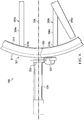
- FIG. 3 a close-up view of the curved stator 203a is shown that details how the curved stator 203a (and by extension the curved stator 203b) is coupled to the inner wall 213 and the fan hub 217. For clarity, fan blades 215a, 215b, 215c, 215d, 215e and the vanes 209a and 209b are omitted.
- a first end 219a of the curved stator 203a is coupled to the inner wall 213.
- the first end 219a is coupled to the inner wall 213 using a mechanical fastener.
- the first end 219a and the inner wall 213 can be coupled using bolt assemblies, snap-fit assemblies, adhesive bonds, other common bonding methods, or in any other suitable manner.
- the second end 221a of the curved stator 203a is also coupled to the inner wall 213. Like with the first end 219a, there are multiple suitable alternative means by which the second end 221a can be coupled to the inner wall 213.
- the curved stator 203a is coupled to the fan hub 217 along the length of the curved portion 204c.
- the connection of the curved stator 203a to the fan hub 217 can be substantially centered about the inflection point 227a.
- the curved stator 203a is coupled to the fan hub 217 using a mechanical fastener.
- the curved stator 203a and the fan hub 217 can be coupled using bolt assemblies, snap-fit assemblies, adhesive bonds, other common bonding methods, or in any other suitable manner.
- the curved stator 203a and the fan hub 217 are coupled proximate to the curved stator's inflection point 227a, the curved stator 203a can effectively transfer forces and moments generated by the fan hub 217 away from the fan hub 217 to the surrounding structure.
- the curved stators 203a, 203b are situated to allow easy assembly and disassembly of the fan hub 217. More specifically, the fan hub 217 can be disassembled from the ducted fan assembly 201 by simply decoupling the fan hub 217 from the curved stators 203a, 203b. The fan hub 217 can then be repaired or replaced without disassembling the curved stators 203a, 203b from the ducted fan assembly 201. Instead, for example, the curved stator 203a can remain coupled to the inner wall 213 at the first end 219a and the second end 221a. The fan hub 217 can then be reassembled by recoupling the fan hub 217 with the curved stators 203a, 203b.
- FIG. 4 illustrates a side view of the ducted fan assembly 201, wherein the duct 207 has been omitted for clarity.
- the curved stator 203b and vane 209b are also blocked from view.
- a vertical plane 231 runs through the center of the fan hub 217, proximate to the inflection points 227a and 227b of curved stators 203a and 203b, respectively.
- the curved stators 203a and 203b both have 5-degrees of taper measured respectively from the inflection points 227a and 227b to the first ends 219a and 219b.
- the curved stators 203a and 203b both have 5-degrees of taper measured respectively from the inflection points 227a and 227b to the second ends 221a and 221b.
- the curved stators' 203a and 203b profiles are aerodynamically shaped to better accommodate the airflow during operations.
- curved stators can comprise airfoils comprising cambered profiles.
- FIG. 5 illustrates a wing assembly 300 comprising a wing 331 and a ducted fan assembly 301 with curved stators 303a and 303b.
- the ducted fan assembly 301 comprises a duct 307 comprising an inner wall 313 and an outer wall 311. The remaining structure of the ducted fan assembly 301 is disposed within a substantially cylindrical space defined by the duct 307.
- the ducted fan assembly 301 comprises a central axis 305.
- the ducted fan assembly 301 also comprises a fan hub 317 and five fan blades 315a, 315b, 315c, 315d, and 315e.
- the fan hub 317 is disposed substantially coaxially with the central axis 305 and is coupled to the five fan blades 315a, 315b, 315c, 315d, 315e.
- the fan blades 315a, 315b, 315c, 315d, 315e each generally extend radially relative to the central axis 305 and are disposed in an evenly distributed angular array so that adjacent blades are substantially similarly angularly offset from each other.
- the ducted fan assembly 301 further comprises two curved stators 303a and 303b that are coupled to the inner wall 313.
- the curved stators 303a and 303b are also coupled to the fan hub 317 and are used to hold the fan hub 317 in place, relative to the duct 307.
- the curved stators 303a and 303b are located downstream relative to the fan blades 315a, 315b, 315c, 315d, 315e, and within the airflow generated by the spinning fan blades 315a, 315b, 315c, 315d, 315e during operation.
- the curved stator 303a comprises a substantially straight inboard portion 304a, a substantially straight outboard portion 304b, and a curved portion 304c that joins the inboard portion 304a to the outboard portion 304b.
- the curved stator 303b comprises a substantially straight inboard portion 306a, a substantially straight outboard portion 306b, and a curved portion 306c that joins the inboard portion 306a to the outboard portion 306b.
- Each of the curved portions 304c and 306c comprise an inflection point 337a at which a curved profile of the curved portions 304c, 306c transition from sloping upward (+) to sloping downward (-) or vice versa.
- the entire body of a curved stator may comprise a curved profile, without substantially straight portions, which nonetheless comprises a point of inflection that demarks a general change in curvature direction of a body of the curved stator 303a.
- a curved stator can comprise a plurality of straight portions that, while the portions are individually substantially straight, the straight portions nonetheless collectively provide a curvature to the overall profile of the curved stator.
- a first end 319a of the curved stator 303a is coupled to the inner wall 313.
- the first end 319a is coupled to the inner wall 313 using a mechanical fastener.
- the first end 319a and the inner wall 313 can be coupled using bold assemblies, snap-fit assemblies, adhesive bonds, other common bonding methods, or in any other suitable manner.
- the second end 321a of the curved stator 303a is also coupled to the inner wall 313 using a mechanical fastener. Like with the first end 319a, there are multiple suitable alternative means by which the second end 321a can be coupled to the inner wall 313.
- the curved stator 303a is coupled to the fan hub 317 along the length of the curved portion 304c.
- the connection of the curved stator 303a to the fan hub 317 can be substantially centered about the inflection point 337a.
- the curved stator 303a is coupled to the fan hub 317 using a mechanical fastener.
- the curved stator 303a and the fan hub 317 can be coupled using bolt assemblies, snap-fit assemblies, adhesive bonds, other common bonding methods, or in any other suitable manner.
- the curved stator 303a can effectively transfer forces and moments generated by the fan hub 217 away from the fan 317 to the surrounding structure. More generally, the curved stator 303a can be described as being coupled to the fan hub 317 at a hub interface 338a of the curved stator 303a, the hub interface 338a being located between the first end 319a and the second end 321a. In some cases, the hub interface can be associated with an overall lengthwise midpoint along the length of the curved stator 303a.
- the curved stator 303b can be described as being coupled to the fan hub 317 at a hub interface 338b of the curved stator 303b, the hub interface 338b being located between the first end 319b and the second end 321b.
- the hub interface can be associated with an overall lengthwise midpoint along the length of the curved stator 303b.
- a close-up view of a pivot joint 335 is provided.
- the pivot joint 335 is used to couple the outer wall 311 with a wing tip 333.
- the pivot joint 335 allows the ducted fan assembly 301 to selectively rotate about a pivot joint axis 339.
- the pivot joint axis 339 extends through the center of the pivot joint 335 and intersects the central axis 305.
- the ducted fan assembly 301 is configured to produce forward thrust force; but the pivot joint 335 allows the ducted fan assembly 301 to pivot about the pivot joint axis 339 to produce a lifting force, or a combination thereof.
- the pivot joint 335 is attached to an actuator 337 that is used to mechanically pivot the ducted fan assembly 301 about the pivot joint axis 339.
- the pivot joint 335 is coupled to the outer wall 311 at an angular location along the outer wall 311 adjacent to and between the curved stators' first ends 319a and 319b, so that the curved stators 303a and 303b are bilaterally symmetric about the pivot joint axis 339.
- R l a numerical range with a lower limit, R l , and an upper limit, R u .
- R l any number falling within the range is specifically disclosed.
- any numerical range defined by two R numbers as defined in the above is also specifically disclosed.
Landscapes
- Engineering & Computer Science (AREA)
- Aviation & Aerospace Engineering (AREA)
- Mechanical Engineering (AREA)
- General Engineering & Computer Science (AREA)
- Physics & Mathematics (AREA)
- Geometry (AREA)
- Structures Of Non-Positive Displacement Pumps (AREA)
Abstract
Description
- A ducted fan is a propulsive apparatus in which a plurality of propulsive fan blades are disposed within a duct. Multiple vehicles use ducted fans to generate propulsion and perform a multitude of functions. Such functions include generating forward thrust, generating lift, and generating antitorque. For example, air and sea vehicles, like the Bell X-22 and the Landing Craft Air Cushion (LCAC), respectively, use ducted fans to generate forward thrust. In some cases, vertical take off and landing (VTOL) aircraft and other air vehicles, like the Martin Jetpack, use ducted fans to generate lift. Also, several helicopter models use ducted fans, in some cases in the form of fenestrons, to generate antitorque and yaw moments during operations.
- Conventional ducted fans generally comprise a duct that houses a mechanical fan at its center. During operations, the mechanical fan generates a propulsive force by using a power source to spin a plurality of propulsive fan blades. Because the mechanical fan functions within the confines of the duct, the mechanical fan must be secured in place to prevent the fan blades from striking the walls of the duct.
- Conventional ducted fans use stators to provide structural support to the mechanical fan and hold it in place relative to the duct. Conventional stators are generally straight, long, narrow, and fixed at their ends to both the mechanical fan and the duct. Conventional stators tend to be radially oriented about the center of the duct but can alternatively be radially offset. The conventional stators are disposed behind the fan blades and are usually aerodynamically shaped to allow easy passage of the airflow generated by the mechanical fan.
-
-
FIGS. 1A-1B show a vertical take off and landing (VTOL) aircraft with ducted fans that are oriented to primarily generate lift and forward thrust, respectively. -
FIGS. 2A-2B are oblique views of a ducted fan assembly of VTOL aircraft ofFIG. 1 . -
FIG. 2C is a top view of the ducted fan assembly ofFIG. 2A . -
FIG. 2D is a bottom view of the ducted fan assembly ofFIG. 2A . -
FIG. 3 is a close-up top view of the ducted fan assembly ofFIG. 2A , showing the ducted fan assembly isolated from the fan blades and vanes for clarity. -
FIG. 4 is a side view of the ducted fan assembly ofFIG. 2A , showing the ducted fan assembly isolated from the duct for clarity. -
FIG. 5 is a schematic top view of a wing assembly of the present disclosure, showing a wing coupled with a ducted fan assembly. -
FIG. 6 is a close-up top view of the wing assembly ofFIG. 5 . - While the making and using of various embodiments of this disclosure are discussed in detail below, it should be appreciated that this disclosure provides many applicable inventive concepts, which can be embodied in a wide variety of specific contexts. The specific embodiments discussed herein are merely illustrative and do not limit the scope of this disclosure. In the interest of clarity, not all features of an actual implementation may be described in this disclosure. It will of course be appreciated that in the development of any such actual embodiment, numerous implementation-specific decisions must be made to achieve the developer's specific goals, such as compliance with system-related and business-related constraints, which will vary from one implementation to another.
- In this disclosure, reference may be made to the spatial relationships between various components and to the spatial orientation of various aspects of components as the devices are depicted in the attached drawings. However, as will be recognized by those skilled in the art after a complete reading of this disclosure, the devices, members, apparatuses, etc. described herein may be positioned in any desired orientation. Thus, the use of terms such as "above," "below," "upper," "lower," or other like terms to describe a spatial relationship between various components or to describe the spatial orientation of aspects of such components should be understood to describe a relative relationship between the components or a spatial orientation of aspects of such components, respectively, as the device described herein may be oriented in any desired direction. In addition, the use of the term "coupled" throughout this disclosure may mean directly or indirectly connected, moreover, "coupled" may also mean permanently or removably connected, unless otherwise stated.
-
FIGS. 1A and1B are illustrative examples of a Vertical Takeoff and Lift (VTOL)aircraft 101 comprising afuselage 103, anempennage 105, and two ductedfan assemblies wing 109. -
FIG. 1A shows theVTOL aircraft 101 comprising ductedfan assemblies VTOL aircraft 101 and bring it into a hover above the ground. -
FIG. 1B shows theVTOL aircraft 101 comprising ductedfan assemblies aircraft 101 is in a hover, ductedfan assemblies 201 produce thrust that propels the VTOLaircraft 101 forward into forward flight. - Referring now to
FIGS 2A-2D , a ductedfan assembly 201 comprisingcurved stators FIGS. 2A and2B show oblique views of the ductedfan assembly 201.FIGS. 2C and2D show a top and bottom view, respectively, of the ductedfan assembly 201. - Referring to
FIGS. 2A-2D , theducted fan assembly 201 comprises aduct 207. Theduct 207 comprises aninner wall 213 and anouter wall 211. In this embodiment, the remaining structure of theducted fan assembly 201 is housed within a substantially cylindrical space defined by theduct 207. - A
fan hub 217 is disposed at least partially along thecentral axis 205. Thefan hub 217 is coupled to fivefan blades fan blades fan blades central axis 205 and are disposed in an evenly distributed angular array so that adjacent blades are substantially similarly angularly offset from each other. - The ducted
fan assembly 201 further comprises twocurved stators inner wall 213. Thecurved stators fan hub 217 and are used to hold thefan hub 217 in place, relative to theduct 207. Thecurved stators fan blades fan blades - In this embodiment, the
curved stator 203a comprises a substantially straightinboard portion 204a, a substantiallystraight outboard portion 204b, and acurved portion 204c that joins theinboard portion 204a to theoutboard portion 204b. Similarly, thecurved stator 203b comprises a substantially straightinboard portion 206a, a substantiallystraight outboard portion 206b, and acurved portion 206c that joins theinboard portion 206a to theoutboard portion 206b. Each of thecurved portions inflection point 227a at which a curved profile of thecurved portions curved stator 203a. In the embodiment pictured inFIG. 3 , thecurved stator 203a curves angularly at a 112-degree angle. More generally, thecurved stator 203a can be described as being coupled to thefan hub 217 at a hub interface 238a of thecurved stator 203a, the hub interface 238a being located between thefirst end 219a and thesecond end 221a. In some cases, the hub interface can be associated with an overall lengthwise midpoint along the length of thecurved stator 203a. Similarly, thecurved stator 203b can be described as being coupled to thefan hub 217 at a hub interface 238b of thecurved stator 203b, the hub interface 238b being located between the first end 219b and the second end 221b. In some cases, the hub interface can be associated with an overall lengthwise midpoint along the length of thecurved stator 203b. - In the embodiment pictured in
FIGS. 2A-2D , thecurved stators central axis 205. In other words, theducted fan assembly 201 is identical about aplane 230 that is coincident with thecentral axis 205. - Two
vanes curved stators vanes FIGS. 2A-2D , to perturb and direct airflow downstream of thefan blades vanes fan hub 217 and extend outward towards theinner wall 213. Thevanes curved stators FIGS. 2A-2D . - Referring to
FIG. 3 , a close-up view of thecurved stator 203a is shown that details how thecurved stator 203a (and by extension thecurved stator 203b) is coupled to theinner wall 213 and thefan hub 217. For clarity,fan blades vanes - A
first end 219a of thecurved stator 203a is coupled to theinner wall 213. In this embodiment, thefirst end 219a is coupled to theinner wall 213 using a mechanical fastener. However, in alternative embodiments, thefirst end 219a and theinner wall 213 can be coupled using bolt assemblies, snap-fit assemblies, adhesive bonds, other common bonding methods, or in any other suitable manner. Thesecond end 221a of thecurved stator 203a is also coupled to theinner wall 213. Like with thefirst end 219a, there are multiple suitable alternative means by which thesecond end 221a can be coupled to theinner wall 213. - In this embodiment, the
curved stator 203a is coupled to thefan hub 217 along the length of thecurved portion 204c. In some embodiments, the connection of thecurved stator 203a to thefan hub 217 can be substantially centered about theinflection point 227a. In this embodiment, thecurved stator 203a is coupled to thefan hub 217 using a mechanical fastener. However, in alternative embodiments, thecurved stator 203a and thefan hub 217 can be coupled using bolt assemblies, snap-fit assemblies, adhesive bonds, other common bonding methods, or in any other suitable manner. In part because thecurved stator 203a and thefan hub 217 are coupled proximate to the curved stator'sinflection point 227a, thecurved stator 203a can effectively transfer forces and moments generated by thefan hub 217 away from thefan hub 217 to the surrounding structure. - In addition to transferring forces and moments generated by the
fan hub 217, thecurved stators fan hub 217. More specifically, thefan hub 217 can be disassembled from theducted fan assembly 201 by simply decoupling thefan hub 217 from thecurved stators fan hub 217 can then be repaired or replaced without disassembling thecurved stators ducted fan assembly 201. Instead, for example, thecurved stator 203a can remain coupled to theinner wall 213 at thefirst end 219a and thesecond end 221a. Thefan hub 217 can then be reassembled by recoupling thefan hub 217 with thecurved stators -
FIG. 4 illustrates a side view of theducted fan assembly 201, wherein theduct 207 has been omitted for clarity. Thecurved stator 203b andvane 209b are also blocked from view. Avertical plane 231 runs through the center of thefan hub 217, proximate to theinflection points 227a and 227b ofcurved stators curved stators inflection points 227a and 227b to the first ends 219a and 219b. Likewise, thecurved stators inflection points 227a and 227b to the second ends 221a and 221b. The curved stators' 203a and 203b profiles are aerodynamically shaped to better accommodate the airflow during operations. In alternative embodiments, curved stators can comprise airfoils comprising cambered profiles. -
FIG. 5 illustrates awing assembly 300 comprising awing 331 and aducted fan assembly 301 withcurved stators ducted fan assembly 301 comprises aduct 307 comprising aninner wall 313 and anouter wall 311. The remaining structure of theducted fan assembly 301 is disposed within a substantially cylindrical space defined by theduct 307. - The
ducted fan assembly 301 comprises acentral axis 305. Theducted fan assembly 301 also comprises a fan hub 317 and fivefan blades central axis 305 and is coupled to the fivefan blades fan blades central axis 305 and are disposed in an evenly distributed angular array so that adjacent blades are substantially similarly angularly offset from each other. - The
ducted fan assembly 301 further comprises twocurved stators inner wall 313. Thecurved stators duct 307. Thecurved stators fan blades fan blades - In this embodiment, the
curved stator 303a comprises a substantially straightinboard portion 304a, a substantially straightoutboard portion 304b, and acurved portion 304c that joins theinboard portion 304a to theoutboard portion 304b. Similarly, thecurved stator 303b comprises a substantially straightinboard portion 306a, a substantially straightoutboard portion 306b, and acurved portion 306c that joins theinboard portion 306a to theoutboard portion 306b. Each of thecurved portions curved portions curved stator 303a. In yet other alternative embodiments, a curved stator can comprise a plurality of straight portions that, while the portions are individually substantially straight, the straight portions nonetheless collectively provide a curvature to the overall profile of the curved stator. - A
first end 319a of thecurved stator 303a is coupled to theinner wall 313. In this embodiment, thefirst end 319a is coupled to theinner wall 313 using a mechanical fastener. However, in alternative embodiments, thefirst end 319a and theinner wall 313 can be coupled using bold assemblies, snap-fit assemblies, adhesive bonds, other common bonding methods, or in any other suitable manner. The second end 321a of thecurved stator 303a is also coupled to theinner wall 313 using a mechanical fastener. Like with thefirst end 319a, there are multiple suitable alternative means by which the second end 321a can be coupled to theinner wall 313. - In this embodiment, the
curved stator 303a is coupled to the fan hub 317 along the length of thecurved portion 304c. In some embodiments, the connection of thecurved stator 303a to the fan hub 317 can be substantially centered about the inflection point 337a. In this embodiment, thecurved stator 303a is coupled to the fan hub 317 using a mechanical fastener. However, in alternative embodiments, thecurved stator 303a and the fan hub 317 can be coupled using bolt assemblies, snap-fit assemblies, adhesive bonds, other common bonding methods, or in any other suitable manner. In part because thecurved stator 303a and the fan hub 317 are coupled proximate to the curved stator's point of inflection 327a, thecurved stator 303a can effectively transfer forces and moments generated by thefan hub 217 away from the fan 317 to the surrounding structure. More generally, thecurved stator 303a can be described as being coupled to the fan hub 317 at a hub interface 338a of thecurved stator 303a, the hub interface 338a being located between thefirst end 319a and the second end 321a. In some cases, the hub interface can be associated with an overall lengthwise midpoint along the length of thecurved stator 303a. More generally, thecurved stator 303b can be described as being coupled to the fan hub 317 at a hub interface 338b of thecurved stator 303b, the hub interface 338b being located between thefirst end 319b and the second end 321b. In some cases, the hub interface can be associated with an overall lengthwise midpoint along the length of thecurved stator 303b. - Referring to
FIG. 6 , a close-up view of a pivot joint 335 is provided. The pivot joint 335 is used to couple theouter wall 311 with awing tip 333. The pivot joint 335 allows theducted fan assembly 301 to selectively rotate about a pivotjoint axis 339. The pivotjoint axis 339 extends through the center of the pivot joint 335 and intersects thecentral axis 305. As shown inFIG.5 , theducted fan assembly 301 is configured to produce forward thrust force; but the pivot joint 335 allows theducted fan assembly 301 to pivot about the pivotjoint axis 339 to produce a lifting force, or a combination thereof. - Still referring to
FIG. 6 , the pivot joint 335 is attached to anactuator 337 that is used to mechanically pivot theducted fan assembly 301 about the pivotjoint axis 339. The pivot joint 335 is coupled to theouter wall 311 at an angular location along theouter wall 311 adjacent to and between the curved stators' first ends 319a and 319b, so that thecurved stators joint axis 339. - At least one embodiment is disclosed, and variations, combinations, and/or modifications of the embodiment(s) and/or features of the embodiment(s) made by a person having ordinary skill in the art are within the scope of the disclosure. Alternative embodiments that result from combining, integrating, and/or omitting features of the embodiment(s) are also within the scope of the disclosure. Where numerical ranges or limitations are expressly stated, such express ranges or limitations should be understood to include iterative ranges or limitations of like magnitude falling within the expressly stated ranges or limitations (e.g., from about 1 to about 10 includes, 2, 3, 4, etc.; greater than 0.10 includes 0.11, 0.12, 0.13, etc.). For example, whenever a numerical range with a lower limit, Rl, and an upper limit, Ru, is disclosed, any number falling within the range is specifically disclosed. In particular, the following numbers within the range are specifically disclosed: R=Rl +k * (Ru-Rl), wherein k is a variable ranging from 1 percent to 100 percent with a 1 percent increment, i.e., k is 1 percent, 2 percent, 3 percent, 4 percent, 5 percent,... 50 percent, 51 percent, 52 percent,..., 95 percent, 96 percent, 95 percent, 98 percent, 99 percent, or 100 percent. Moreover, any numerical range defined by two R numbers as defined in the above is also specifically disclosed. Use of the term "optionally" with respect to any element of a claim means that the element is required, or alternatively, the element is not required, both alternatives being within the scope of the claim. Use of broader terms such as comprises, includes, and having should be understood to provide support for narrower terms such as consisting of, consisting essentially of, and comprised substantially of. Accordingly, the scope of protection is not limited by the description set out above but is defined by the claims that follow, that scope including all equivalents of the subject matter of the claims. Each and every claim is incorporated as further disclosure into the specification and the claims are embodiment(s) of the present invention. Also, the phrases "at least one of A, B, and C" and "A and/or B and/or C" should each be interpreted to include only A, only B, only C, or any combination of A, B, and C.
Claims (15)
- A ducted fan assembly, comprising:a central axis;a duct, the duct comprising:an outer wall; andan inner wall;a fan hub at least partially disposed on the central axis;a plurality of fan blades coupled to the fan hub; anda first stator, the first stator comprising:a first end coupled to the inner wall;a second end coupled to the inner wall; anda hub interface disposed between the first end and the second end,wherein the hub interface is coupled to the fan hub.
- The ducted fan assembly according to claim 1, wherein the first stator comprises a curved portion that comprises the hub interface.
- The ducted fan assembly according to claim 1, further comprising:
a second stator, the second stator comprising:a first end coupled to the inner wall;a second end coupled to the inner wall; anda hub interface disposed between the first end of the second stator and the second end of the second stator, wherein the hub interface of the second stator is coupled to the fan hub. - The ducted fan assembly according to claim 3, wherein the first stator and the second stator are bilaterally symmetrical to one another about a plane through the central axis.
- The ducted fan assembly according to claim 4, wherein the second stator comprises a curved portion that comprises the hub interface.
- The ducted fan assembly according to any preceding claim, wherein a vane is coupled to the fan hub and extends radially outward toward the inner wall, and optionally or preferably, wherein the vane is coupled to and runs partially along a length of the first stator.
- The ducted fan assembly according to claim 2, wherein the curved portion of the first stator angularly curves in an obtuse angle, and optionally or preferably, wherein the curved portion of the first stator angularly curves at a 112-degree angle.
- The ducted fan assembly according to any preceding claim, wherein the first stator is tapered from the first end to a lengthwise midpoint and is tapered from the second end to the midpoint, and optionally or preferably, wherein the first stator comprises 5 degrees of taper from the first end to the midpoint and 5 degrees of taper from the second end to the midpoint.
- The ducted fan assembly according to any preceding claim, wherein the ducted fan assembly comprises five fan blades, and optionally or preferably, wherein each of the five fan blades are angularly spaced evenly apart from one another.
- A method for assembling and disassembling a fan hub from a ducted fan assembly, the method comprising:providing a ducted fan assembly, comprising:a central axis;a duct, the duct comprising:an outer wall; andan inner wall;a fan hub at least partially disposed on the central axis;a plurality of fan blades coupled to the fan hub; anda first stator, the first stator comprising:a first end coupled to the inner wall;a second end coupled to the inner wall; anda hub interface disposed between the first end and the second end,wherein the hub interface is coupled to the fan hub; andcoupling or decoupling the fan hub relative to the hub interface without decoupling the first stator from the inner wall.
- The method of claim 10, wherein hub interface is disposed on a curved portion of the first stator and wherein the fan hub is coupled or decoupled from the curved portion without decoupling the first end from the inner wall and without decoupling the second end from the inner wall.
- A wing assembly, comprising:a wing comprising a wing tip; anda ducted fan assembly coupled to the wing, the ducted fan assembly comprising:a central axis;a duct, the duct comprising:an outer wall; andan inner wall;a fan hub at least partially disposed on the central axis;a plurality of fan blades coupled to the fan hub; anda first stator, the first stator comprising:a first end coupled to the inner wall;a second end coupled to the inner wall; anda hub interface disposed between the first end and the second end, wherein the hub interface is coupled to the fan hub.
- The wing assembly according to claim 12, wherein the wing tip is coupled to the outer wall of the duct.
- The wing assembly according to claim 13, wherein the wing tip is coupled to the outer wall of the duct with a pivot joint that allows the ducted fan assembly to selectively rotate about a pivot joint axis.
- The wing assembly according to claim 14, the ducted fan assembly further comprising:
a second stator, the second stator comprising:a first end coupled to the inner wall;a second end coupled to the inner wall; anda hub interface disposed between the first end of the second stator and the second end of the second stator, wherein the hub interface of the second stator is coupled to the fan hub, and optionally or preferably, wherein the first stator and the second stator are bilaterally symmetrical to one another about a plane through the pivot joint axis and the central axis.
Applications Claiming Priority (1)
| Application Number | Priority Date | Filing Date | Title |
|---|---|---|---|
| US16/247,726 US11673648B2 (en) | 2019-01-15 | 2019-01-15 | Ducted fan assembly with curved stators |
Publications (2)
| Publication Number | Publication Date |
|---|---|
| EP3683446A1 true EP3683446A1 (en) | 2020-07-22 |
| EP3683446B1 EP3683446B1 (en) | 2022-08-03 |
Family
ID=69172665
Family Applications (1)
| Application Number | Title | Priority Date | Filing Date |
|---|---|---|---|
| EP20151927.9A Active EP3683446B1 (en) | 2019-01-15 | 2020-01-15 | Ducted fan assembly with curved stators |
Country Status (2)
| Country | Link |
|---|---|
| US (1) | US11673648B2 (en) |
| EP (1) | EP3683446B1 (en) |
Families Citing this family (12)
| Publication number | Priority date | Publication date | Assignee | Title |
|---|---|---|---|---|
| CN118083115A (en) | 2017-08-10 | 2024-05-28 | 保罗·奈瑟 | Device and method for fluid manipulation |
| US12570391B2 (en) | 2017-08-10 | 2026-03-10 | Paul NEISER | Apparatus and method for fluid manipulation |
| US12270301B2 (en) * | 2017-08-10 | 2025-04-08 | Paul NEISER | System and method for fluid manipulation |
| US11267564B2 (en) * | 2019-10-22 | 2022-03-08 | Textron Innovations Inc. | Aircraft with rotating ducted fan |
| USD919548S1 (en) * | 2020-01-03 | 2021-05-18 | Bell Textron Inc. | Ducted rotor |
| USD919547S1 (en) * | 2020-01-03 | 2021-05-18 | Bell Textron Inc. | Aircraft fuselage |
| USD920213S1 (en) * | 2020-01-03 | 2021-05-25 | Bell Textron Inc. | Aircraft |
| USD966170S1 (en) * | 2020-10-28 | 2022-10-11 | Manta Aircraft SA | Aircraft |
| US11827344B2 (en) * | 2020-12-09 | 2023-11-28 | Textron Innovations Inc. | Low noise ducted fan |
| DE102021132911A1 (en) * | 2021-12-14 | 2023-06-15 | Dr. Ing. H.C. F. Porsche Aktiengesellschaft | Lift unit for an aircraft and aircraft with such a lift unit |
| US12145753B2 (en) * | 2022-08-09 | 2024-11-19 | Pete Bitar | Compact and lightweight drone delivery device called an ArcSpear electric jet drone system having an electric ducted air propulsion system and being relatively difficult to track in flight |
| CN122161757A (en) * | 2023-11-09 | 2026-06-05 | 阿罗菲克斯公司 | Thrust vectoring thruster |
Citations (4)
| Publication number | Priority date | Publication date | Assignee | Title |
|---|---|---|---|---|
| EP0661206A1 (en) * | 1992-12-28 | 1995-07-05 | Hughes Missile Systems Company | An unmanned vertical take-off and landing, horizontal cruise, air vehicle |
| EP1384662A1 (en) * | 2002-07-26 | 2004-01-28 | C.R.F. Società Consortile per Azioni | Vtol micro-aircraft |
| US20150023791A1 (en) * | 2012-03-06 | 2015-01-22 | Ziehl-Abegg Se | Axial Fan |
| EP3290336A1 (en) * | 2016-08-31 | 2018-03-07 | Bell Helicopter Textron Inc. | Tilting ducted fan aircraft generating a pitch control moment |
Family Cites Families (3)
| Publication number | Priority date | Publication date | Assignee | Title |
|---|---|---|---|---|
| US6170778B1 (en) * | 1999-04-22 | 2001-01-09 | Sikorsky Aircraft Corporation | Method of reducing a nose-up pitching moment on a ducted unmanned aerial vehicle |
| US20040200924A1 (en) * | 2003-01-29 | 2004-10-14 | Clark Leonard R. | Radio-controlled flying toy |
| US8109802B2 (en) * | 2007-09-15 | 2012-02-07 | Mattel, Inc. | Toy helicopter having a stabilizing bumper |
-
2019
- 2019-01-15 US US16/247,726 patent/US11673648B2/en active Active
-
2020
- 2020-01-15 EP EP20151927.9A patent/EP3683446B1/en active Active
Patent Citations (4)
| Publication number | Priority date | Publication date | Assignee | Title |
|---|---|---|---|---|
| EP0661206A1 (en) * | 1992-12-28 | 1995-07-05 | Hughes Missile Systems Company | An unmanned vertical take-off and landing, horizontal cruise, air vehicle |
| EP1384662A1 (en) * | 2002-07-26 | 2004-01-28 | C.R.F. Società Consortile per Azioni | Vtol micro-aircraft |
| US20150023791A1 (en) * | 2012-03-06 | 2015-01-22 | Ziehl-Abegg Se | Axial Fan |
| EP3290336A1 (en) * | 2016-08-31 | 2018-03-07 | Bell Helicopter Textron Inc. | Tilting ducted fan aircraft generating a pitch control moment |
Also Published As
| Publication number | Publication date |
|---|---|
| US20200223530A1 (en) | 2020-07-16 |
| US11673648B2 (en) | 2023-06-13 |
| EP3683446B1 (en) | 2022-08-03 |
Similar Documents
| Publication | Publication Date | Title |
|---|---|---|
| EP3683446B1 (en) | Ducted fan assembly with curved stators | |
| EP3483064B1 (en) | Tilting proprotor with segmented duct | |
| US10577091B2 (en) | Vertical take-off and landing aircraft | |
| US10457380B2 (en) | Articulated rotor systems with pitch independent damping | |
| US10518868B2 (en) | Soft-in-plane proprotor systems | |
| US11480072B2 (en) | Stator and duct ring structural fittings | |
| US10793254B2 (en) | Soft-in-plane proprotor systems | |
| AU2019200047B2 (en) | Composite fan blades with integral attachment mechanism | |
| WO2019203673A4 (en) | Personal flight apparatus with vertical take-off and landing | |
| US11472533B2 (en) | Stators located aft of duct ring | |
| US11827344B2 (en) | Low noise ducted fan | |
| US20200391859A1 (en) | Vtol aircraft with leading edge tilting ducted fans | |
| US12017761B2 (en) | Rotor centrifugal force retention device | |
| US11548630B2 (en) | Conversion spindle with dual ducted tiltrotors | |
| US20180162526A1 (en) | Proprotor Systems for Tiltrotor Aircraft | |
| US10518867B2 (en) | Loop yoke for proprotor systems | |
| US11702196B2 (en) | Rotor system with reconfigurable duct | |
| US20210139139A1 (en) | Bonded skins for ducted-rotor aircraft | |
| US11242139B2 (en) | Spindle to primary duct stator attachment | |
| CN114056556B (en) | aircraft | |
| JP7684980B2 (en) | Rib mounting flange for unmanned aerial vehicles | |
| CN107108020B (en) | Rotorcraft with streamlined outer profile | |
| US11643186B2 (en) | Duct for ducted-rotor aircraft | |
| KR102130467B1 (en) | Braced wing aircraft | |
| US11845534B2 (en) | Slanted duct stators |
Legal Events
| Date | Code | Title | Description |
|---|---|---|---|
| STAA | Information on the status of an ep patent application or granted ep patent |
Free format text: STATUS: EXAMINATION IS IN PROGRESS |
|
| PUAI | Public reference made under article 153(3) epc to a published international application that has entered the european phase |
Free format text: ORIGINAL CODE: 0009012 |
|
| 17P | Request for examination filed |
Effective date: 20200115 |
|
| AK | Designated contracting states |
Kind code of ref document: A1 Designated state(s): AL AT BE BG CH CY CZ DE DK EE ES FI FR GB GR HR HU IE IS IT LI LT LU LV MC MK MT NL NO PL PT RO RS SE SI SK SM TR |
|
| GRAP | Despatch of communication of intention to grant a patent |
Free format text: ORIGINAL CODE: EPIDOSNIGR1 |
|
| STAA | Information on the status of an ep patent application or granted ep patent |
Free format text: STATUS: GRANT OF PATENT IS INTENDED |
|
| INTG | Intention to grant announced |
Effective date: 20220218 |
|
| RIN1 | Information on inventor provided before grant (corrected) |
Inventor name: AMANTE, WILLIAM A. Inventor name: CARPENTER JR., RICHARD JOSEPH |
|
| GRAS | Grant fee paid |
Free format text: ORIGINAL CODE: EPIDOSNIGR3 |
|
| GRAA | (expected) grant |
Free format text: ORIGINAL CODE: 0009210 |
|
| STAA | Information on the status of an ep patent application or granted ep patent |
Free format text: STATUS: THE PATENT HAS BEEN GRANTED |
|
| RAP1 | Party data changed (applicant data changed or rights of an application transferred) |
Owner name: TEXTRON INNOVATIONS INC. |
|
| AK | Designated contracting states |
Kind code of ref document: B1 Designated state(s): AL AT BE BG CH CY CZ DE DK EE ES FI FR GB GR HR HU IE IS IT LI LT LU LV MC MK MT NL NO PL PT RO RS SE SI SK SM TR |
|
| REG | Reference to a national code |
Ref country code: AT Ref legal event code: REF Ref document number: 1508954 Country of ref document: AT Kind code of ref document: T Effective date: 20220815 Ref country code: CH Ref legal event code: EP |
|
| REG | Reference to a national code |
Ref country code: DE Ref legal event code: R096 Ref document number: 602020004248 Country of ref document: DE |
|
| REG | Reference to a national code |
Ref country code: IE Ref legal event code: FG4D |
|
| REG | Reference to a national code |
Ref country code: LT Ref legal event code: MG9D |
|
| REG | Reference to a national code |
Ref country code: NL Ref legal event code: MP Effective date: 20220803 |
|
| PG25 | Lapsed in a contracting state [announced via postgrant information from national office to epo] |
Ref country code: SE Free format text: LAPSE BECAUSE OF FAILURE TO SUBMIT A TRANSLATION OF THE DESCRIPTION OR TO PAY THE FEE WITHIN THE PRESCRIBED TIME-LIMIT Effective date: 20220803 Ref country code: RS Free format text: LAPSE BECAUSE OF FAILURE TO SUBMIT A TRANSLATION OF THE DESCRIPTION OR TO PAY THE FEE WITHIN THE PRESCRIBED TIME-LIMIT Effective date: 20220803 Ref country code: PT Free format text: LAPSE BECAUSE OF FAILURE TO SUBMIT A TRANSLATION OF THE DESCRIPTION OR TO PAY THE FEE WITHIN THE PRESCRIBED TIME-LIMIT Effective date: 20221205 Ref country code: NO Free format text: LAPSE BECAUSE OF FAILURE TO SUBMIT A TRANSLATION OF THE DESCRIPTION OR TO PAY THE FEE WITHIN THE PRESCRIBED TIME-LIMIT Effective date: 20221103 Ref country code: NL Free format text: LAPSE BECAUSE OF FAILURE TO SUBMIT A TRANSLATION OF THE DESCRIPTION OR TO PAY THE FEE WITHIN THE PRESCRIBED TIME-LIMIT Effective date: 20220803 Ref country code: LV Free format text: LAPSE BECAUSE OF FAILURE TO SUBMIT A TRANSLATION OF THE DESCRIPTION OR TO PAY THE FEE WITHIN THE PRESCRIBED TIME-LIMIT Effective date: 20220803 Ref country code: LT Free format text: LAPSE BECAUSE OF FAILURE TO SUBMIT A TRANSLATION OF THE DESCRIPTION OR TO PAY THE FEE WITHIN THE PRESCRIBED TIME-LIMIT Effective date: 20220803 Ref country code: FI Free format text: LAPSE BECAUSE OF FAILURE TO SUBMIT A TRANSLATION OF THE DESCRIPTION OR TO PAY THE FEE WITHIN THE PRESCRIBED TIME-LIMIT Effective date: 20220803 Ref country code: ES Free format text: LAPSE BECAUSE OF FAILURE TO SUBMIT A TRANSLATION OF THE DESCRIPTION OR TO PAY THE FEE WITHIN THE PRESCRIBED TIME-LIMIT Effective date: 20220803 |
|
| REG | Reference to a national code |
Ref country code: AT Ref legal event code: MK05 Ref document number: 1508954 Country of ref document: AT Kind code of ref document: T Effective date: 20220803 |
|
| PG25 | Lapsed in a contracting state [announced via postgrant information from national office to epo] |
Ref country code: PL Free format text: LAPSE BECAUSE OF FAILURE TO SUBMIT A TRANSLATION OF THE DESCRIPTION OR TO PAY THE FEE WITHIN THE PRESCRIBED TIME-LIMIT Effective date: 20220803 Ref country code: IS Free format text: LAPSE BECAUSE OF FAILURE TO SUBMIT A TRANSLATION OF THE DESCRIPTION OR TO PAY THE FEE WITHIN THE PRESCRIBED TIME-LIMIT Effective date: 20221203 Ref country code: HR Free format text: LAPSE BECAUSE OF FAILURE TO SUBMIT A TRANSLATION OF THE DESCRIPTION OR TO PAY THE FEE WITHIN THE PRESCRIBED TIME-LIMIT Effective date: 20220803 Ref country code: GR Free format text: LAPSE BECAUSE OF FAILURE TO SUBMIT A TRANSLATION OF THE DESCRIPTION OR TO PAY THE FEE WITHIN THE PRESCRIBED TIME-LIMIT Effective date: 20221104 |
|
| PG25 | Lapsed in a contracting state [announced via postgrant information from national office to epo] |
Ref country code: SM Free format text: LAPSE BECAUSE OF FAILURE TO SUBMIT A TRANSLATION OF THE DESCRIPTION OR TO PAY THE FEE WITHIN THE PRESCRIBED TIME-LIMIT Effective date: 20220803 Ref country code: RO Free format text: LAPSE BECAUSE OF FAILURE TO SUBMIT A TRANSLATION OF THE DESCRIPTION OR TO PAY THE FEE WITHIN THE PRESCRIBED TIME-LIMIT Effective date: 20220803 Ref country code: DK Free format text: LAPSE BECAUSE OF FAILURE TO SUBMIT A TRANSLATION OF THE DESCRIPTION OR TO PAY THE FEE WITHIN THE PRESCRIBED TIME-LIMIT Effective date: 20220803 Ref country code: CZ Free format text: LAPSE BECAUSE OF FAILURE TO SUBMIT A TRANSLATION OF THE DESCRIPTION OR TO PAY THE FEE WITHIN THE PRESCRIBED TIME-LIMIT Effective date: 20220803 Ref country code: AT Free format text: LAPSE BECAUSE OF FAILURE TO SUBMIT A TRANSLATION OF THE DESCRIPTION OR TO PAY THE FEE WITHIN THE PRESCRIBED TIME-LIMIT Effective date: 20220803 |
|
| REG | Reference to a national code |
Ref country code: DE Ref legal event code: R097 Ref document number: 602020004248 Country of ref document: DE |
|
| PG25 | Lapsed in a contracting state [announced via postgrant information from national office to epo] |
Ref country code: SK Free format text: LAPSE BECAUSE OF FAILURE TO SUBMIT A TRANSLATION OF THE DESCRIPTION OR TO PAY THE FEE WITHIN THE PRESCRIBED TIME-LIMIT Effective date: 20220803 Ref country code: EE Free format text: LAPSE BECAUSE OF FAILURE TO SUBMIT A TRANSLATION OF THE DESCRIPTION OR TO PAY THE FEE WITHIN THE PRESCRIBED TIME-LIMIT Effective date: 20220803 |
|
| PLBE | No opposition filed within time limit |
Free format text: ORIGINAL CODE: 0009261 |
|
| STAA | Information on the status of an ep patent application or granted ep patent |
Free format text: STATUS: NO OPPOSITION FILED WITHIN TIME LIMIT |
|
| PG25 | Lapsed in a contracting state [announced via postgrant information from national office to epo] |
Ref country code: AL Free format text: LAPSE BECAUSE OF FAILURE TO SUBMIT A TRANSLATION OF THE DESCRIPTION OR TO PAY THE FEE WITHIN THE PRESCRIBED TIME-LIMIT Effective date: 20220803 |
|
| 26N | No opposition filed |
Effective date: 20230504 |
|
| P01 | Opt-out of the competence of the unified patent court (upc) registered |
Effective date: 20230602 |
|
| PG25 | Lapsed in a contracting state [announced via postgrant information from national office to epo] |
Ref country code: SI Free format text: LAPSE BECAUSE OF FAILURE TO SUBMIT A TRANSLATION OF THE DESCRIPTION OR TO PAY THE FEE WITHIN THE PRESCRIBED TIME-LIMIT Effective date: 20220803 |
|
| REG | Reference to a national code |
Ref country code: CH Ref legal event code: PL |
|
| PG25 | Lapsed in a contracting state [announced via postgrant information from national office to epo] |
Ref country code: LU Free format text: LAPSE BECAUSE OF NON-PAYMENT OF DUE FEES Effective date: 20230115 |
|
| REG | Reference to a national code |
Ref country code: BE Ref legal event code: MM Effective date: 20230131 |
|
| PG25 | Lapsed in a contracting state [announced via postgrant information from national office to epo] |
Ref country code: LI Free format text: LAPSE BECAUSE OF NON-PAYMENT OF DUE FEES Effective date: 20230131 Ref country code: CH Free format text: LAPSE BECAUSE OF NON-PAYMENT OF DUE FEES Effective date: 20230131 |
|
| PG25 | Lapsed in a contracting state [announced via postgrant information from national office to epo] |
Ref country code: BE Free format text: LAPSE BECAUSE OF NON-PAYMENT OF DUE FEES Effective date: 20230131 |
|
| PG25 | Lapsed in a contracting state [announced via postgrant information from national office to epo] |
Ref country code: IE Free format text: LAPSE BECAUSE OF NON-PAYMENT OF DUE FEES Effective date: 20230115 |
|
| PG25 | Lapsed in a contracting state [announced via postgrant information from national office to epo] |
Ref country code: MC Free format text: LAPSE BECAUSE OF FAILURE TO SUBMIT A TRANSLATION OF THE DESCRIPTION OR TO PAY THE FEE WITHIN THE PRESCRIBED TIME-LIMIT Effective date: 20220803 |
|
| PG25 | Lapsed in a contracting state [announced via postgrant information from national office to epo] |
Ref country code: MC Free format text: LAPSE BECAUSE OF FAILURE TO SUBMIT A TRANSLATION OF THE DESCRIPTION OR TO PAY THE FEE WITHIN THE PRESCRIBED TIME-LIMIT Effective date: 20220803 |
|
| PG25 | Lapsed in a contracting state [announced via postgrant information from national office to epo] |
Ref country code: BG Free format text: LAPSE BECAUSE OF FAILURE TO SUBMIT A TRANSLATION OF THE DESCRIPTION OR TO PAY THE FEE WITHIN THE PRESCRIBED TIME-LIMIT Effective date: 20220803 |
|
| PG25 | Lapsed in a contracting state [announced via postgrant information from national office to epo] |
Ref country code: BG Free format text: LAPSE BECAUSE OF FAILURE TO SUBMIT A TRANSLATION OF THE DESCRIPTION OR TO PAY THE FEE WITHIN THE PRESCRIBED TIME-LIMIT Effective date: 20220803 |
|
| PG25 | Lapsed in a contracting state [announced via postgrant information from national office to epo] |
Ref country code: CY Free format text: LAPSE BECAUSE OF FAILURE TO SUBMIT A TRANSLATION OF THE DESCRIPTION OR TO PAY THE FEE WITHIN THE PRESCRIBED TIME-LIMIT; INVALID AB INITIO Effective date: 20200115 |
|
| PG25 | Lapsed in a contracting state [announced via postgrant information from national office to epo] |
Ref country code: HU Free format text: LAPSE BECAUSE OF FAILURE TO SUBMIT A TRANSLATION OF THE DESCRIPTION OR TO PAY THE FEE WITHIN THE PRESCRIBED TIME-LIMIT; INVALID AB INITIO Effective date: 20200115 |
|
| PG25 | Lapsed in a contracting state [announced via postgrant information from national office to epo] |
Ref country code: TR Free format text: LAPSE BECAUSE OF FAILURE TO SUBMIT A TRANSLATION OF THE DESCRIPTION OR TO PAY THE FEE WITHIN THE PRESCRIBED TIME-LIMIT Effective date: 20220803 |
|
| PGFP | Annual fee paid to national office [announced via postgrant information from national office to epo] |
Ref country code: GB Payment date: 20260127 Year of fee payment: 7 |
|
| PGFP | Annual fee paid to national office [announced via postgrant information from national office to epo] |
Ref country code: DE Payment date: 20260128 Year of fee payment: 7 |
|
| PGFP | Annual fee paid to national office [announced via postgrant information from national office to epo] |
Ref country code: IT Payment date: 20260121 Year of fee payment: 7 |
|
| PGFP | Annual fee paid to national office [announced via postgrant information from national office to epo] |
Ref country code: FR Payment date: 20260126 Year of fee payment: 7 |