EP3683432A1 - Fuel evaporative gas emission suppressing device - Google Patents
Fuel evaporative gas emission suppressing device Download PDFInfo
- Publication number
- EP3683432A1 EP3683432A1 EP18856733.3A EP18856733A EP3683432A1 EP 3683432 A1 EP3683432 A1 EP 3683432A1 EP 18856733 A EP18856733 A EP 18856733A EP 3683432 A1 EP3683432 A1 EP 3683432A1
- Authority
- EP
- European Patent Office
- Prior art keywords
- pressure
- canister
- opening
- evaporative gas
- closing section
- Prior art date
- Legal status (The legal status is an assumption and is not a legal conclusion. Google has not performed a legal analysis and makes no representation as to the accuracy of the status listed.)
- Granted
Links
Images



Classifications
-
- F—MECHANICAL ENGINEERING; LIGHTING; HEATING; WEAPONS; BLASTING
- F02—COMBUSTION ENGINES; HOT-GAS OR COMBUSTION-PRODUCT ENGINE PLANTS
- F02M—SUPPLYING COMBUSTION ENGINES IN GENERAL WITH COMBUSTIBLE MIXTURES OR CONSTITUENTS THEREOF
- F02M25/00—Engine-pertinent apparatus for adding non-fuel substances or small quantities of secondary fuel to combustion-air, main fuel or fuel-air mixture
- F02M25/08—Engine-pertinent apparatus for adding non-fuel substances or small quantities of secondary fuel to combustion-air, main fuel or fuel-air mixture adding fuel vapours drawn from engine fuel reservoir
- F02M25/0809—Judging failure of purge control system
-
- F—MECHANICAL ENGINEERING; LIGHTING; HEATING; WEAPONS; BLASTING
- F02—COMBUSTION ENGINES; HOT-GAS OR COMBUSTION-PRODUCT ENGINE PLANTS
- F02M—SUPPLYING COMBUSTION ENGINES IN GENERAL WITH COMBUSTIBLE MIXTURES OR CONSTITUENTS THEREOF
- F02M25/00—Engine-pertinent apparatus for adding non-fuel substances or small quantities of secondary fuel to combustion-air, main fuel or fuel-air mixture
- F02M25/08—Engine-pertinent apparatus for adding non-fuel substances or small quantities of secondary fuel to combustion-air, main fuel or fuel-air mixture adding fuel vapours drawn from engine fuel reservoir
-
- F—MECHANICAL ENGINEERING; LIGHTING; HEATING; WEAPONS; BLASTING
- F02—COMBUSTION ENGINES; HOT-GAS OR COMBUSTION-PRODUCT ENGINE PLANTS
- F02M—SUPPLYING COMBUSTION ENGINES IN GENERAL WITH COMBUSTIBLE MIXTURES OR CONSTITUENTS THEREOF
- F02M25/00—Engine-pertinent apparatus for adding non-fuel substances or small quantities of secondary fuel to combustion-air, main fuel or fuel-air mixture
- F02M25/08—Engine-pertinent apparatus for adding non-fuel substances or small quantities of secondary fuel to combustion-air, main fuel or fuel-air mixture adding fuel vapours drawn from engine fuel reservoir
- F02M25/0836—Arrangement of valves controlling the admission of fuel vapour to an engine, e.g. valve being disposed between fuel tank or absorption canister and intake manifold
-
- F—MECHANICAL ENGINEERING; LIGHTING; HEATING; WEAPONS; BLASTING
- F02—COMBUSTION ENGINES; HOT-GAS OR COMBUSTION-PRODUCT ENGINE PLANTS
- F02D—CONTROLLING COMBUSTION ENGINES
- F02D41/00—Electrical control of supply of combustible mixture or its constituents
- F02D41/22—Safety or indicating devices for abnormal conditions
- F02D2041/224—Diagnosis of the fuel system
- F02D2041/225—Leakage detection
-
- F—MECHANICAL ENGINEERING; LIGHTING; HEATING; WEAPONS; BLASTING
- F02—COMBUSTION ENGINES; HOT-GAS OR COMBUSTION-PRODUCT ENGINE PLANTS
- F02D—CONTROLLING COMBUSTION ENGINES
- F02D2200/00—Input parameters for engine control
- F02D2200/02—Input parameters for engine control the parameters being related to the engine
- F02D2200/06—Fuel or fuel supply system parameters
- F02D2200/0602—Fuel pressure
-
- F—MECHANICAL ENGINEERING; LIGHTING; HEATING; WEAPONS; BLASTING
- F02—COMBUSTION ENGINES; HOT-GAS OR COMBUSTION-PRODUCT ENGINE PLANTS
- F02M—SUPPLYING COMBUSTION ENGINES IN GENERAL WITH COMBUSTIBLE MIXTURES OR CONSTITUENTS THEREOF
- F02M25/00—Engine-pertinent apparatus for adding non-fuel substances or small quantities of secondary fuel to combustion-air, main fuel or fuel-air mixture
- F02M25/08—Engine-pertinent apparatus for adding non-fuel substances or small quantities of secondary fuel to combustion-air, main fuel or fuel-air mixture adding fuel vapours drawn from engine fuel reservoir
- F02M2025/0845—Electromagnetic valves
-
- F—MECHANICAL ENGINEERING; LIGHTING; HEATING; WEAPONS; BLASTING
- F02—COMBUSTION ENGINES; HOT-GAS OR COMBUSTION-PRODUCT ENGINE PLANTS
- F02M—SUPPLYING COMBUSTION ENGINES IN GENERAL WITH COMBUSTIBLE MIXTURES OR CONSTITUENTS THEREOF
- F02M25/00—Engine-pertinent apparatus for adding non-fuel substances or small quantities of secondary fuel to combustion-air, main fuel or fuel-air mixture
- F02M25/08—Engine-pertinent apparatus for adding non-fuel substances or small quantities of secondary fuel to combustion-air, main fuel or fuel-air mixture adding fuel vapours drawn from engine fuel reservoir
- F02M25/0854—Details of the absorption canister
Definitions
- This disclosure relates to a fuel evaporative gas emission suppressing device which introduces a fuel evaporative gas within a fuel tank into an air intake system of an engine to suppress its emission into the atmosphere.
- the disclosure relates, in particular, to a technology for detecting a fuel evaporative gas leak.
- a fuel evaporative gas generated within a fuel tank presents a cause of air pollution.
- a vehicle loaded with an engine generally has a fuel evaporative gas treating device installed therein for suppressing the emission of the fuel evaporative gas into the atmosphere.
- the fuel evaporative gas treating device is configured, for example, to connect the fuel tank with an air intake system of the engine by a purge pipeline equipped with a canister, allow a fuel evaporative gas generated in the fuel tank to be once adsorbed to activated carbon within the canister, and introduce the activated carbon-adsorbed fuel into the air intake system of the engine in accordance with the negative pressure of intake air in the engine, thereby burning the fuel together with fresh air.
- PHEV plug-in hybrid electric vehicle
- HEV hybrid electric vehicle
- a so-called closed fuel evaporative gas emission suppressing device a device having a sealing valve provided between the fuel tank and the canister for bringing the sealing valve to a closed state during stoppage of the engine, is under development.
- closed fuel evaporative gas emission suppressing devices is one designed, for example, to provide an opening/closing valve near the inlet of the canister so that when the opening/closing valve is closed, a fuel evaporative gas is not introduced into the canister, but directly introduced into the air intake system of the engine.
- a device for example, in which with a canister space including a canister and a purge passage being closed, the internal pressure of the canister space is changed and, based on a change in the internal pressure of the canister space on this occasion, leakage diagnosis (detection of whether or not there is a leak) of the canister space is made (see Patent Document 1).
- Patent Document 1 Japanese Patent No. 3849584
- An aspect of the present invention has been accomplished in the light of the above-described circumstances. It is an object of an aspect of the invention to provide a fuel evaporative gas emission suppressing device which can determine the presence or absence of a fuel evaporative gas leak and which makes it easy to pinpoint the location of the leak.
- An aspect of the present invention resides in a fuel evaporative gas emission suppressing device comprising: a first communication path for bringing an intake air passage of an engine of a vehicle and a canister into communication; a second communication path branching off from a bifurcation provided in the first communication path, and communicating with a fuel tank; a third communication path for bringing the canister and outside air into communication; a first opening/closing section provided in the first communication path between the intake air passage and the bifurcation for opening up and cutting off the communication to the intake air passage; a second opening/closing section provided in the second communication path for opening up and cutting off the communication to the fuel tank; a third opening/closing section provided in the first communication path between the bifurcation and the canister for opening up and cutting off the communication to the canister; a fourth opening/closing section provided in the third communication path for opening up and cutting off the communication to the outside air; a pressure generating section disposed in the third communication path for generating a pressure in the can
- the leak determination unit determines the presence or absence of the fuel evaporative gas leak based on a first pressure change amount which is a difference between an initial pressure of the canister and the first pressure, and a second pressure change amount which is a difference between the initial pressure and the second pressure.
- the leak determination unit preferably determines that the fuel evaporative gas leak is present in a closed space of the communication paths closed by the first opening/closing section, the second opening/closing section, and the third opening/closing section, on condition that the ratio of the second pressure change amount to the first pressure change amount is equal to or higher than a preset determination threshold value.
- the leak determination unit determines that the fuel evaporative gas leak is absent in the closed space of the communication paths, on condition that the ratio of the second pressure change amount to the first pressure change amount is lower than the determination threshold value, and further determines the presence or absence of the fuel evaporative gas leak based on a third pressure change amount which is a difference between the initial pressure and a reference pressure of the canister detected after detection of the second pressure.
- the leak determination unit preferably determines that the fuel evaporative gas leak is present in the canister, if the second pressure change amount is equal to or smaller than the third pressure change amount.
- the reference pressure refers, concretely, to the pressure inside the canister in a state where the third opening/closing section and the fourth opening/closing section are opened after the lapse of the second predetermined period.
- the presence or absence of a fuel evaporative gas leak in the fuel evaporative gas emission suppressing device can be determined properly, and the location of the leak is easy to pinpoint.
- a fuel evaporative gas emission suppressing device 10 is a device which is loaded on a vehicle of an automobile or the like for suppressing the emission, into the atmosphere, of a fuel evaporative gas (vapor) generated within a fuel tank 101 for storing fuel to be supplied to an engine 100.
- the fuel evaporative gas emission suppressing device 10 is equipped with a canister 12 having activated carbon sealed therein.
- the canister 12, the fuel tank 101, and an intake air passage 102 of the engine 100 are connected together by connecting piping 13.
- the connecting piping 13 includes purge piping (first communication path) 14 for bringing the intake air passage 102 of the engine 100 and the canister 12 into communication, vapor piping (second communication path) 16 branching off from a bifurcation 14a provided in the purge piping 14 and communicating with the fuel tank 101, and vent piping (third communication path) 24 for bringing the canister 12 and the atmosphere into communication.
- the canister 12 communicates with the intake air passage 102 of the engine 100 via the purge piping (first communication path) 14.
- the fuel tank 101 communicates with the bifurcation 14a of the purge piping 14 via the vapor piping (second communication path) 16.
- the vapor piping 16 is provided with a tank pressure sensor (tank pressure detecting section) 17 for detecting the pressure inside the fuel tank 101.
- the purge piping 14 is provided with a purge valve (first opening/closing section) 18 for opening and closing the flow of a fuel evaporative gas to the intake air passage 102 (communication between the intake air passage 102 and the canister 12).
- the open and closed states of the purge valve 18 are switched as appropriate, whereby the state of supply of fuel (fuel evaporative gas) adsorbed by the canister 12 to the intake air passage 102 is controlled.
- the purge valve 18 is driven, for example, by an electromagnetic solenoid.
- the purge valve 18 is a so-called normally closed type electromagnetic valve which is closed when the electromagnetic solenoid is not energized, but is opened when the electromagnetic solenoid is energized.
- the vapor piping 16 namely, its portion branching off from the purge piping 14 and located beside the fuel tank 101 with respect to the bifurcation 14a, is provided with a sealing valve (second opening/closing section) 20 which becomes open and closed for sealing the fuel tank 101. Furthermore, a portion of the purge piping 14 beside the canister 12 with respect to the bifurcation 14a is provided with a bypass valve (third opening/closing section) 22.
- the sealing valve 20 is a so-called normally closed type electromagnetic valve like the purge valve 18, while the bypass valve 22 is a so-called normally open type electromagnetic valve unlike the purge valve 18.
- the vent piping (third communication path) 24 is connected to the canister 12, and the canister 12 communicates with the outside via the vent piping 24.
- Halfway through the vent piping 24 is provided an evaporative leak check module (ELCM) 26 for detecting a leak of the fuel evaporative gas from the fuel tank 101, the canister 12, and the connecting piping 13 including the purge piping 14 and the vapor piping 16 linked to these components.
- ELCM evaporative leak check module
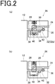
- the ELCM 26 as shown in Figs. 2(a), 2(b) , is equipped with a first flow path 28 communicating with the canister 12, a second flow path 30 open to the atmosphere via the vent piping 24, and a third flow path 32 connected halfway between the first flow path 28 and the second flow path 30.
- a switching valve (fourth opening/closing section) 34 is provided between the first flow path 28 and the second flow path 30/third flow path 32.
- the connection between the first flow path 28 and the second flow path 30 or the third flow path 32 is adapted to be switchable by the switching valve 34.
- the switching valve 34 allows the first flow path 28 and the second flow path 30 to communicate in a state where the electromagnetic solenoid is not energized, but allows the first flow path 28 and the third flow path 32 to communicate in a state where the electromagnetic solenoid is energized.
- the third flow path 32 is provided with a negative pressure pump 36 which generates a negative pressure within the canister 12.
- the first flow path 28 and the third flow path 32 have a fourth flow path 38 provided astride the switching valve 34.
- the fourth flow path 38 is provided with a reference orifice 40, for example, with a diameter of 0.45 mm, and a canister pressure sensor (canister pressure detecting section) 42 for detecting the pressure inside the canister 12 is provided beside the second flow path 30 with respect to the reference orifice 40.
- canister pressure canister pressure detecting section
- the above-mentioned negative pressure pump (pressure generating section) 36 and switching valve 34 constituting the ELCM 26, and the purge valve 18, sealing valve 20, and bypass valve 22 mentioned above are controlled based on control signals from an ECU (control section) 50.
- the control section 50 may be provided independently for each of the purge valve 18, sealing valve 20, and bypass valve 22.
- the ECU 50 is equipped with a leak determination unit 51.
- the leak determination unit 51 executes the leak determination of a fuel evaporative gas in the canister 12 and the connecting piping 13. Concretely, while operating the negative pressure pump 36 to reduce the pressure inside the canister 12, the ECU 50 switches the sealing valve 20 from a closed state to an open state and, based on a pressure change in the canister 12, determines the presence or absence of a leak in the canister 12 and the connecting piping 13, or determines where a leak is occurring.
- the canister 12, the target for leak determination means the closed space of the canister 12 closed by the bypass valve 22.
- the connecting piping 13 for which leak determination is performed means the closed space of the communication paths (purge piping 14 and vapor piping 16) closed by the purge valve 18, sealing valve 20 and bypass valve 22.
- the leak determination unit 51 If it is determined by the leak determination unit 51 that there is a leak of a fuel evaporative gas, the driver is warned, for example, by lighting a warning lamp for leak indication which is provided near the driver's seat.
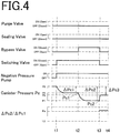
- Figs. 3 to 5 are timing charts showing chronologically the operating states of each valve and the negative pressure pump, canister pressure, etc. in leak determination.
- the pressure inside the canister 12 is first brought to an initial value (e.g., atmospheric pressure) P0, then at a time t1, the purge valve 18 and the sealing valve 20 are closed, the bypass valve 22 is opened, and the switching valve 34 is closed. In this state, the negative pressure pump 36 is actuated.
- the purge valve 18 and the sealing valve 20 are not operated, while the switching valve 34, a normally open type electromagnetic valve, is actuated to be switched from an open state to a closed state, and the negative pressure pump 36 is operated.
- a first pressure P c 1 the canister pressure P c at a time t2, has the first value P1.
- the canister pressure P c does not decrease to the first value P1, but as shown in Figs. 4 and 5 , decreases only to a second value P2 (>P1).
- the first pressure P c 1 the canister pressure P c at the time t2, has the second value P2.
- the bypass valve 22 is switched from the open state to the closed state. That is, at a timing when after a lapse of a preset first predetermined period (t1-t2), the change (decrease) in the canister pressure P c settles, the bypass valve 22 is operated to be switched from the open state to the closed state. In this state, the operation of the negative pressure pump 36 is continued to a time t3 to reduce the pressure within the canister 12. A change in the canister pressure P c is detected by the canister pressure sensor 42.
- the pressure inside the canister 12 decreases to the first value P1.
- a second pressure P c 2 the canister pressure P c at the time t3, has the first value P1.
- the canister pressure P c (first pressure P c 1) reaches the first value P1, for example, the canister pressure P c is maintained at the first value P1 at a time later than the time t2, and the canister pressure P c detected at the time t3 (second pressure P c 2) is also held at the first value P1, as shown in Fig. 3 .
- the canister pressure P c at the time t2 (first pressure P c 1) takes the second value P2 (failing to reach the first value P1), on the other hand, the canister pressure P c decreases to the first value P1 at a time later than the time t2, as shown in Fig. 4 . Therefore, the canister pressure P c detected at the time t3 (second pressure P c 2) takes the first value P1.
- the canister pressure P c is maintained at the pressure existent at the point in time of the time t2.
- first pressure P c 1 first pressure P2
- second pressure P c 2 second pressure P3
- the canister pressure P c does not lower to the first value P1, but changes stepwise, although this is not shown. If the canister pressure P c detected at the time t2 (first pressure P c 1) has the second value P2, for example, the canister pressure P c detected at the time t3 (second pressure P c 2) takes a third value which is higher than the first value P1 and lower than the second value P2.
- the operation of the bypass valve 22 and the switching valve 34 is stopped to switch their status from the closed state to the open state. That is, at a timing when a preset second predetermined period (t2-t3) has passed, and the change (decrease) in the canister pressure P c settles, the bypass valve 22 and the switching valve 34 are switched from the closed state to the open state.
- the operation of the negative pressure pump 36 is continued.
- the reference pressure P b of the canister pressure P c is detected. If, at the time t3, the bypass valve 22 and the switching valve 34 are switched from the closed state to the open state, for example, a negative pressure is generated only in a space 32a (see Fig. 2(a) ) between the negative pressure pump 36 on the third flow path 32 and the reference orifice 40. Then, at a timing when changes in the canister pressure P c settle (e.g., at a time t4), the pressure in the space 32a is detected as the reference pressure P b of the canister pressure P c .
- the canister pressure P c detected at the time t3 (second pressure P c 2) is lower than the reference pressure P b , the canister pressure P c rises at a time later than the time t3 (see Fig. 3 ).
- the canister pressure P c (second pressure P c 2) is lower than the reference pressure P b at the time t3.
- the canister pressure P c detected at the time t3 (second pressure P c 2) is higher than the reference pressure P b (see, for example, Fig. 5 ), on the other hand, the canister pressure P c further decreases at a time later than the time t3.
- the canister pressure P c (second pressure P c 2) is higher than the reference pressure P b at the point in time of the time t3.
- the leak determination unit 51 determines the presence or absence of a leak in the canister 12 and the connecting piping 13 based on the canister pressure P c changing as above. In the present embodiment, the leak determination unit 51 determines the presence or absence of a leak in the connecting piping 13 at the timing of the time t3, and determines the presence or absence of a leak in the canister 12 at the timing of the time t4.
- the leak determination unit 51 determines the presence or absence of a leak of a fuel evaporative gas based on the first pressure P C 1 which is the canister pressure P c at the time t2, and the second pressure P c 2 which is the canister pressure P c at the time t3.
- the leak determination unit 51 first determines whether or not there is a leak hole in the connecting piping 13, based on a first pressure change amount ⁇ P c 1 which is the difference (pressure decrease amount) between the initial pressure (atmospheric pressure) P0 and the first pressure P c 1 of the canister pressure P c , and a second pressure change amount ⁇ P c 2 which is the difference (pressure decrease amount) between the initial pressure P0 and the second pressure P c 2 of the canister pressure P c .
- a first pressure change amount ⁇ P c 1 which is the difference (pressure decrease amount) between the initial pressure (atmospheric pressure) P0 and the first pressure P c 1 of the canister pressure P c
- ⁇ P c 2 which is the difference (pressure decrease amount) between the initial pressure P0 and the second pressure P c 2 of the canister pressure P c .
- the leak determination unit 51 determines whether or not there is a leak hole in the connecting piping 13, based on the first pressure change amount ⁇ P c 1 and the second pressure change amount ⁇ P c 2 which are the decrease amounts of the canister pressure P c .
- the leak determination unit 51 determines that a leak hole is present in the connecting piping 13, if the ratio ( ⁇ P c 2/ ⁇ P c 1) of the second pressure change amount ⁇ P c 2 to the first pressure change amount ⁇ P c 1 is equal to or higher than a preset determination threshold value P a (>1). The driver is informed of this fact for warning.
- the lead determination unit 51 determines that a leak hole exists in the connecting piping 13.
- the leak determination unit 51 determines that a fuel evaporative gas leak is absent (there is no leak hole) in the connecting piping (first to third communication paths) 13, and then determines the presence or absence of a fuel evaporative gas leak in the canister 12.
- the leak determination unit 51 determines the presence or absence of a leak in the canister 12, based on the reference pressure P b of the canister pressure P c . Concretely, if the second pressure change amount ⁇ P c 2 detected at the time t3 is equal to or smaller than a third pressure change amount ⁇ P c 3 which is the difference between the initial pressure (atmospheric pressure) P0 and the reference pressure P b of the canister 12, the leak determination unit 51 determines that a leak in the canister 12 is present, and warns the driver of this fact.
- the leak determination unit 51 determines that a leak in the canister 12 is present, and warns the driver of this fact.
- the leak determination unit 51 determines that there is no leak in the canister 12. In other words, if the reference pressure P b is higher than the canister pressure P c at the time t3 (second pressure P c 2), the leak determination unit 51 determines that there is no leak in the canister 12. That is, if no leak hole exists in the canister 12, or the diameter of the leak hole, if any, is smaller than the reference orifice 40, the leak determination unit 51 determines that there is no leak in the canister 12.
- the leak determination unit 51 executes leak determination to determine the presence or absence of a fuel evaporative gas leak in the canister 12 and the connecting piping 13. This feature makes it possible to determine appropriately the presence or absence of a fuel evaporative gas leak, and to specify the location of leak to some extent.
- the configuration having the negative pressure pump for generating a negative pressure in the canister is illustrated as the pressure generating section.
- a booster pump for pressurizing (generating a positive pressure in) the canister may be provided as the pressure generating section. That is, leak determination can be executed, with the canister pressure being brought to a positive pressure.
- the presence or absence of a leak is determined based on the ratio of the second pressure change amount to the first pressure change amount.
- the leak determination according to the aspect of the present invention may be performed based on the first pressure and the second pressure serving as the canister pressure. For example, leak determination can be made based on a deviation between the first pressure change amount and the second pressure change amount.
Landscapes
- Engineering & Computer Science (AREA)
- Chemical & Material Sciences (AREA)
- Combustion & Propulsion (AREA)
- Mechanical Engineering (AREA)
- General Engineering & Computer Science (AREA)
- Supplying Secondary Fuel Or The Like To Fuel, Air Or Fuel-Air Mixtures (AREA)
- Examining Or Testing Airtightness (AREA)
Abstract
Description
- This disclosure relates to a fuel evaporative gas emission suppressing device which introduces a fuel evaporative gas within a fuel tank into an air intake system of an engine to suppress its emission into the atmosphere. The disclosure relates, in particular, to a technology for detecting a fuel evaporative gas leak.
- A fuel evaporative gas generated within a fuel tank presents a cause of air pollution. Thus, a vehicle loaded with an engine generally has a fuel evaporative gas treating device installed therein for suppressing the emission of the fuel evaporative gas into the atmosphere. The fuel evaporative gas treating device is configured, for example, to connect the fuel tank with an air intake system of the engine by a purge pipeline equipped with a canister, allow a fuel evaporative gas generated in the fuel tank to be once adsorbed to activated carbon within the canister, and introduce the activated carbon-adsorbed fuel into the air intake system of the engine in accordance with the negative pressure of intake air in the engine, thereby burning the fuel together with fresh air.
- In recent years, vehicles provided with a traveling motor along with an engine, for example, a plug-in hybrid electric vehicle (PHEV) and a hybrid electric vehicle (HEV), have found practical use. In such a vehicle with a traveling motor, a period during which the engine is stopped, namely, a period in which no fuel can be introduced from the canister into the air intake system of the engine, may last for a relatively long time.
- Hence, a so-called closed fuel evaporative gas emission suppressing device, a device having a sealing valve provided between the fuel tank and the canister for bringing the sealing valve to a closed state during stoppage of the engine, is under development. Among such closed fuel evaporative gas emission suppressing devices is one designed, for example, to provide an opening/closing valve near the inlet of the canister so that when the opening/closing valve is closed, a fuel evaporative gas is not introduced into the canister, but directly introduced into the air intake system of the engine.
- In the above-mentioned fuel evaporative gas emission suppressing device, leakage of a fuel evaporative gas due to a certain trouble directly leads to air pollution. In the United States, etc., therefore, it is legally obligated to detect a fuel evaporative gas leak. Under the legal regulations of the United States, in particular, if a failure self-diagnosis (OBD: On-Board Diagnosis) for detecting such a fuel evaporative gas leak is made and the leak is detected, it is obligated to inform the driver, for example, by lighting a warning lamp. Needless to say, in a closed fuel evaporative gas emission suppressing device as well, it is required to perform leak detection similarly.
- To fulfill such a requirement, a device is available, for example, in which with a canister space including a canister and a purge passage being closed, the internal pressure of the canister space is changed and, based on a change in the internal pressure of the canister space on this occasion, leakage diagnosis (detection of whether or not there is a leak) of the canister space is made (see Patent Document 1).
- Patent Document 1: Japanese Patent No.
3849584 - With the device described in Patent Document 1, it is possible to determine the presence or absence of a leak in the canister space, with the fuel tank being cut off from the canister. The device, however, poses the problem that a fuel evaporative gas leak in a place other than the fuel tank, that is, in the canister space, can be detected, but the location of leakage in the canister space is difficult to pinpoint.
- An aspect of the present invention has been accomplished in the light of the above-described circumstances. It is an object of an aspect of the invention to provide a fuel evaporative gas emission suppressing device which can determine the presence or absence of a fuel evaporative gas leak and which makes it easy to pinpoint the location of the leak.
- An aspect of the present invention resides in a fuel evaporative gas emission suppressing device comprising: a first communication path for bringing an intake air passage of an engine of a vehicle and a canister into communication; a second communication path branching off from a bifurcation provided in the first communication path, and communicating with a fuel tank; a third communication path for bringing the canister and outside air into communication; a first opening/closing section provided in the first communication path between the intake air passage and the bifurcation for opening up and cutting off the communication to the intake air passage; a second opening/closing section provided in the second communication path for opening up and cutting off the communication to the fuel tank; a third opening/closing section provided in the first communication path between the bifurcation and the canister for opening up and cutting off the communication to the canister; a fourth opening/closing section provided in the third communication path for opening up and cutting off the communication to the outside air; a pressure generating section disposed in the third communication path for generating a pressure in the canister; a canister pressure detecting section for detecting the pressure of the canister; and a control section for controlling opening and closing of the first opening/closing section, the second opening/closing section, the third opening/closing section, and the fourth opening/closing section, wherein the control section has a leak determination unit for determining presence or absence of a fuel evaporative gas leak in the fuel evaporative gas emission suppressing device, based on a first pressure which is the pressure of the canister when a first predetermined period has elapsed in a state where the first opening/closing section and the second opening/closing section are closed, the third opening/closing section is opened, the fourth opening/closing section is closed, and the pressure generating section is operated; and a second pressure which is the pressure within the canister when, after a lapse of the first predetermined period, a second predetermined period has elapsed in a state where the third opening/closing section is closed.
- Preferably, the leak determination unit determines the presence or absence of the fuel evaporative gas leak based on a first pressure change amount which is a difference between an initial pressure of the canister and the first pressure, and a second pressure change amount which is a difference between the initial pressure and the second pressure.
- The leak determination unit preferably determines that the fuel evaporative gas leak is present in a closed space of the communication paths closed by the first opening/closing section, the second opening/closing section, and the third opening/closing section, on condition that the ratio of the second pressure change amount to the first pressure change amount is equal to or higher than a preset determination threshold value.
- Preferably, the leak determination unit determines that the fuel evaporative gas leak is absent in the closed space of the communication paths, on condition that the ratio of the second pressure change amount to the first pressure change amount is lower than the determination threshold value, and further determines the presence or absence of the fuel evaporative gas leak based on a third pressure change amount which is a difference between the initial pressure and a reference pressure of the canister detected after detection of the second pressure.
- The leak determination unit preferably determines that the fuel evaporative gas leak is present in the canister, if the second pressure change amount is equal to or smaller than the third pressure change amount.
- The reference pressure refers, concretely, to the pressure inside the canister in a state where the third opening/closing section and the fourth opening/closing section are opened after the lapse of the second predetermined period.
- According to the aspect of the present invention described above, the presence or absence of a fuel evaporative gas leak in the fuel evaporative gas emission suppressing device can be determined properly, and the location of the leak is easy to pinpoint.
-
- [
Fig. 1 ] is a view showing the schematic configuration of a fuel evaporative gas emission suppressing device according to an embodiment of the present invention. - [
Figs. 2(a), 2(b) ] are views showing the schematic configuration of an evaporative leak check module in according with an embodiment. - [
Fig. 3 ] is a timing chart showing the operating state of each valve and so on in leak determination in according with an embodiment. - [
Fig. 4 ] is a timing chart showing the operating state of each valve and so on in leak determination in according with an embodiment. - [
Fig. 5 ] is a timing chart showing the operating state of each valve and so on in leak determination in according with an embodiment. - An embodiment of the present invention will be described in detail below by reference to the accompanying drawings.
- As shown in
Fig. 1 , a fuel evaporative gasemission suppressing device 10 according to the present embodiment is a device which is loaded on a vehicle of an automobile or the like for suppressing the emission, into the atmosphere, of a fuel evaporative gas (vapor) generated within afuel tank 101 for storing fuel to be supplied to anengine 100. - The fuel evaporative gas
emission suppressing device 10 is equipped with acanister 12 having activated carbon sealed therein. Thecanister 12, thefuel tank 101, and anintake air passage 102 of theengine 100 are connected together by connectingpiping 13. - In detail, the connecting
piping 13 includes purge piping (first communication path) 14 for bringing theintake air passage 102 of theengine 100 and thecanister 12 into communication, vapor piping (second communication path) 16 branching off from abifurcation 14a provided in thepurge piping 14 and communicating with thefuel tank 101, and vent piping (third communication path) 24 for bringing thecanister 12 and the atmosphere into communication. - The
canister 12 communicates with theintake air passage 102 of theengine 100 via the purge piping (first communication path) 14. Thefuel tank 101 communicates with thebifurcation 14a of thepurge piping 14 via the vapor piping (second communication path) 16. Thevapor piping 16 is provided with a tank pressure sensor (tank pressure detecting section) 17 for detecting the pressure inside thefuel tank 101. - The
purge piping 14 is provided with a purge valve (first opening/closing section) 18 for opening and closing the flow of a fuel evaporative gas to the intake air passage 102 (communication between theintake air passage 102 and the canister 12). The open and closed states of thepurge valve 18 are switched as appropriate, whereby the state of supply of fuel (fuel evaporative gas) adsorbed by thecanister 12 to theintake air passage 102 is controlled. Thepurge valve 18 is driven, for example, by an electromagnetic solenoid. Thepurge valve 18 is a so-called normally closed type electromagnetic valve which is closed when the electromagnetic solenoid is not energized, but is opened when the electromagnetic solenoid is energized. - The
vapor piping 16, namely, its portion branching off from thepurge piping 14 and located beside thefuel tank 101 with respect to thebifurcation 14a, is provided with a sealing valve (second opening/closing section) 20 which becomes open and closed for sealing thefuel tank 101. Furthermore, a portion of thepurge piping 14 beside thecanister 12 with respect to thebifurcation 14a is provided with a bypass valve (third opening/closing section) 22. Thesealing valve 20 is a so-called normally closed type electromagnetic valve like thepurge valve 18, while thebypass valve 22 is a so-called normally open type electromagnetic valve unlike thepurge valve 18. - The vent piping (third communication path) 24 is connected to the
canister 12, and thecanister 12 communicates with the outside via thevent piping 24. Halfway through thevent piping 24 is provided an evaporative leak check module (ELCM) 26 for detecting a leak of the fuel evaporative gas from thefuel tank 101, thecanister 12, and the connectingpiping 13 including thepurge piping 14 and thevapor piping 16 linked to these components. - The
ELCM 26, as shown inFigs. 2(a), 2(b) , is equipped with afirst flow path 28 communicating with thecanister 12, asecond flow path 30 open to the atmosphere via thevent piping 24, and athird flow path 32 connected halfway between thefirst flow path 28 and thesecond flow path 30. A switching valve (fourth opening/closing section) 34 is provided between thefirst flow path 28 and thesecond flow path 30/third flow path 32. - The connection between the
first flow path 28 and thesecond flow path 30 or thethird flow path 32 is adapted to be switchable by theswitching valve 34. Theswitching valve 34, for example, allows thefirst flow path 28 and thesecond flow path 30 to communicate in a state where the electromagnetic solenoid is not energized, but allows thefirst flow path 28 and thethird flow path 32 to communicate in a state where the electromagnetic solenoid is energized. - The
third flow path 32 is provided with anegative pressure pump 36 which generates a negative pressure within thecanister 12. Thefirst flow path 28 and thethird flow path 32 have afourth flow path 38 provided astride theswitching valve 34. Thefourth flow path 38 is provided with areference orifice 40, for example, with a diameter of 0.45 mm, and a canister pressure sensor (canister pressure detecting section) 42 for detecting the pressure inside thecanister 12 is provided beside thesecond flow path 30 with respect to thereference orifice 40. Hereinafter, the pressure detected by thecanister pressure sensor 42 is referred to simply as "canister pressure". - The above-mentioned negative pressure pump (pressure generating section) 36 and switching
valve 34 constituting theELCM 26, and thepurge valve 18,sealing valve 20, andbypass valve 22 mentioned above are controlled based on control signals from an ECU (control section) 50. Thecontrol section 50 may be provided independently for each of thepurge valve 18,sealing valve 20, andbypass valve 22. - The ECU 50 is equipped with a
leak determination unit 51. Theleak determination unit 51 executes the leak determination of a fuel evaporative gas in thecanister 12 and the connectingpiping 13. Concretely, while operating thenegative pressure pump 36 to reduce the pressure inside thecanister 12, theECU 50 switches the sealingvalve 20 from a closed state to an open state and, based on a pressure change in thecanister 12, determines the presence or absence of a leak in thecanister 12 and the connectingpiping 13, or determines where a leak is occurring. Thecanister 12, the target for leak determination, means the closed space of thecanister 12 closed by thebypass valve 22. The connectingpiping 13 for which leak determination is performed means the closed space of the communication paths (purgepiping 14 and vapor piping 16) closed by thepurge valve 18, sealingvalve 20 andbypass valve 22. - If it is determined by the
leak determination unit 51 that there is a leak of a fuel evaporative gas, the driver is warned, for example, by lighting a warning lamp for leak indication which is provided near the driver's seat. - The procedure for leak determination by the
leak determination unit 51 will be described below by reference toFigs. 3 to 5. Figs. 3 to 5 are timing charts showing chronologically the operating states of each valve and the negative pressure pump, canister pressure, etc. in leak determination. - When the
leak determination unit 51 starts leak determination, the pressure inside thecanister 12 is first brought to an initial value (e.g., atmospheric pressure) P0, then at a time t1, thepurge valve 18 and the sealingvalve 20 are closed, thebypass valve 22 is opened, and the switchingvalve 34 is closed. In this state, thenegative pressure pump 36 is actuated. Actually, thepurge valve 18 and the sealingvalve 20 are not operated, while the switchingvalve 34, a normally open type electromagnetic valve, is actuated to be switched from an open state to a closed state, and thenegative pressure pump 36 is operated. - By this action, a negative pressure is generated within the
canister 12 and the connecting piping 13 (in the space beside thecanister 12 with respect to thepurge valve 18 and the sealing valve 20). A change in the canister pressure Pc is detected by thecanister pressure sensor 42. - If, on this occasion, no leak hole leading to the outside exists in the
canister 12 and the connectingpiping 13 and there is no fuel evaporative gas leak, the pressure inside thecanister 12 and the connecting piping 13 (canister pressure Pc detected by the canister pressure sensor 42) decreases from the initial value (atmospheric pressure) P0 to a first value P1, the lowest value, as shown inFig. 3 . In short, a first pressure Pc1, the canister pressure Pc at a time t2, has the first value P1. - If there is a leak hole in the
canister 12 or the connectingpiping 13, on the other hand, the canister pressure Pc does not decrease to the first value P1, but as shown inFigs. 4 and5 , decreases only to a second value P2 (>P1). In short, the first pressure Pc1, the canister pressure Pc at the time t2, has the second value P2. - Then, at the time t2, the
bypass valve 22 is switched from the open state to the closed state. That is, at a timing when after a lapse of a preset first predetermined period (t1-t2), the change (decrease) in the canister pressure Pc settles, thebypass valve 22 is operated to be switched from the open state to the closed state. In this state, the operation of thenegative pressure pump 36 is continued to a time t3 to reduce the pressure within thecanister 12. A change in the canister pressure Pc is detected by thecanister pressure sensor 42. - If, on this occasion, there is no leak hole in the
canister 12 and no leak of the fuel evaporative gas occurs, the pressure inside the canister 12 (canister pressure Pc) decreases to the first value P1. In short, a second pressure Pc2, the canister pressure Pc at the time t3, has the first value P1. - If, at the time t2, the canister pressure Pc (first pressure Pc1) reaches the first value P1, for example, the canister pressure Pc is maintained at the first value P1 at a time later than the time t2, and the canister pressure Pc detected at the time t3 (second pressure Pc2) is also held at the first value P1, as shown in
Fig. 3 . If the canister pressure Pc at the time t2 (first pressure Pc1) takes the second value P2 (failing to reach the first value P1), on the other hand, the canister pressure Pc decreases to the first value P1 at a time later than the time t2, as shown inFig. 4 . Therefore, the canister pressure Pc detected at the time t3 (second pressure Pc2) takes the first value P1. - If there is no leak hole in the connecting
piping 13, but there is a leak hole in thecanister 12, then the canister pressure Pc is maintained at the pressure existent at the point in time of the time t2. For example, if the canister pressure Pc detected at the time t2 (first pressure Pc1) is of the second value P2, the canister pressure Pc is maintained at the second value P2 at a time later than the time t2, as shown inFig. 5 . That is, the canister pressure Pc detected at the time t3 (second pressure Pc2) also has the second value P2. - If a leak hole exists in each of the
canister 12 and the connectingpiping 13, the canister pressure Pc does not lower to the first value P1, but changes stepwise, although this is not shown. If the canister pressure Pc detected at the time t2 (first pressure Pc1) has the second value P2, for example, the canister pressure Pc detected at the time t3 (second pressure Pc2) takes a third value which is higher than the first value P1 and lower than the second value P2. - Then, at the time t3, the operation of the
bypass valve 22 and the switchingvalve 34 is stopped to switch their status from the closed state to the open state. That is, at a timing when a preset second predetermined period (t2-t3) has passed, and the change (decrease) in the canister pressure Pc settles, thebypass valve 22 and the switchingvalve 34 are switched from the closed state to the open state. - Even in this state, the operation of the
negative pressure pump 36 is continued. By so doing, the reference pressure Pb of the canister pressure Pc is detected. If, at the time t3, thebypass valve 22 and the switchingvalve 34 are switched from the closed state to the open state, for example, a negative pressure is generated only in aspace 32a (seeFig. 2(a) ) between thenegative pressure pump 36 on thethird flow path 32 and thereference orifice 40. Then, at a timing when changes in the canister pressure Pc settle (e.g., at a time t4), the pressure in thespace 32a is detected as the reference pressure Pb of the canister pressure Pc. - If, on this occasion, the canister pressure Pc detected at the time t3 (second pressure Pc2) is lower than the reference pressure Pb, the canister pressure Pc rises at a time later than the time t3 (see
Fig. 3 ). In a case where no leak hole exists in thecanister 12, or the diameter (opening area) of the leak hole, if any, is smaller than thereference orifice 40, the canister pressure Pc (second pressure Pc2) is lower than the reference pressure Pb at the time t3. - If the canister pressure Pc detected at the time t3 (second pressure Pc2) is higher than the reference pressure Pb (see, for example,
Fig. 5 ), on the other hand, the canister pressure Pc further decreases at a time later than the time t3. In a case where there is a leak hole in thecanister 12, and the diameter of the leak hole is larger than thereference orifice 40, the canister pressure Pc (second pressure Pc2) is higher than the reference pressure Pb at the point in time of the time t3. - The
leak determination unit 51 determines the presence or absence of a leak in thecanister 12 and the connectingpiping 13 based on the canister pressure Pc changing as above. In the present embodiment, theleak determination unit 51 determines the presence or absence of a leak in the connectingpiping 13 at the timing of the time t3, and determines the presence or absence of a leak in thecanister 12 at the timing of the time t4. - Concretely, the
leak determination unit 51 determines the presence or absence of a leak of a fuel evaporative gas based on the first pressure PC1 which is the canister pressure Pc at the time t2, and the second pressure Pc2 which is the canister pressure Pc at the time t3. - In the present embodiment, the
leak determination unit 51 first determines whether or not there is a leak hole in the connectingpiping 13, based on a first pressure change amount ΔPc1 which is the difference (pressure decrease amount) between the initial pressure (atmospheric pressure) P0 and the first pressure Pc1 of the canister pressure Pc, and a second pressure change amount ΔPc2 which is the difference (pressure decrease amount) between the initial pressure P0 and the second pressure Pc2 of the canister pressure Pc. - Depending on whether or not there is a leak hole in the connecting
piping 13, as mentioned above, the first pressure change amount ΔPc1 and the second pressure change amount ΔPc2, which are the decrease amounts of the canister pressure Pc in the period (time t1-time t3), undergo changes. Thus, theleak determination unit 51 determines whether or not there is a leak hole in the connectingpiping 13, based on the first pressure change amount ΔPc1 and the second pressure change amount ΔPc2 which are the decrease amounts of the canister pressure Pc. - In detail, the
leak determination unit 51 determines that a leak hole is present in the connectingpiping 13, if the ratio (ΔPc2/ΔPc1) of the second pressure change amount ΔPc2 to the first pressure change amount ΔPc1 is equal to or higher than a preset determination threshold value Pa (>1). The driver is informed of this fact for warning. - If, for example, the canister pressure Pc at the time t2 (the first pressure Pc1) has the second value P2, then the canister pressure Pc decreases, and the canister pressure Pc at the time t3 (the second pressure Pc2) comes to the first value P1, as shown in
Fig. 4 , thelead determination unit 51 determines that a leak hole exists in the connectingpiping 13. - If the ratio (ΔPc2/ΔPc1) of the second pressure change amount ΔPc2 to the first pressure change amount ΔPc1 is lower than the preset determination threshold value Pa (>1), on the other hand, the
leak determination unit 51 determines that a fuel evaporative gas leak is absent (there is no leak hole) in the connecting piping (first to third communication paths) 13, and then determines the presence or absence of a fuel evaporative gas leak in thecanister 12. - Situations where the ratio (ΔPc2/ΔPc1) of the second pressure change amount ΔPc2 to the first pressure change amount ΔPc1 is lower than the determination threshold value Pa include a case in which the canister pressure Pc is maintained at the first value P1 during the period (t2-t3) as shown in
Fig. 4 , and another case in which the canister pressure Pc is maintained at the second value P2 as shown inFig. 5 . Thus, theleak determination unit 51 then determines the presence or absence of a fuel evaporative gas leak in thecanister 12. - In the present embodiment, the
leak determination unit 51 determines the presence or absence of a leak in thecanister 12, based on the reference pressure Pb of the canister pressure Pc. Concretely, if the second pressure change amount ΔPc2 detected at the time t3 is equal to or smaller than a third pressure change amount ΔPc3 which is the difference between the initial pressure (atmospheric pressure) P0 and the reference pressure Pb of thecanister 12, theleak determination unit 51 determines that a leak in thecanister 12 is present, and warns the driver of this fact. In other words, if the reference pressure Pb is equal to or smaller than the canister pressure Pc at the time t3 (second pressure Pc2), theleak determination unit 51 determines that a leak in thecanister 12 is present, and warns the driver of this fact. - If the second pressure change amount ΔPc2 detected at the time t3 is larger than the third pressure change amount ΔPc3 which is the difference between the initial pressure (atmospheric pressure) P0 and the reference pressure Pb of the
canister 12, on the other hand, theleak determination unit 51 determines that there is no leak in thecanister 12. In other words, if the reference pressure Pb is higher than the canister pressure Pc at the time t3 (second pressure Pc2), theleak determination unit 51 determines that there is no leak in thecanister 12. That is, if no leak hole exists in thecanister 12, or the diameter of the leak hole, if any, is smaller than thereference orifice 40, theleak determination unit 51 determines that there is no leak in thecanister 12. - With the aspect of the present invention, as described above, the
leak determination unit 51 executes leak determination to determine the presence or absence of a fuel evaporative gas leak in thecanister 12 and the connectingpiping 13. This feature makes it possible to determine appropriately the presence or absence of a fuel evaporative gas leak, and to specify the location of leak to some extent. - The one embodiment of the present invention has been described above, but the aspect of the invention is not limited to the foregoing embodiment. The invention can be changed or modified, as appropriate, without departing from the spirit of the invention.
- In the above-described embodiment, for example, the configuration having the negative pressure pump for generating a negative pressure in the canister is illustrated as the pressure generating section. However, a booster pump for pressurizing (generating a positive pressure in) the canister may be provided as the pressure generating section. That is, leak determination can be executed, with the canister pressure being brought to a positive pressure.
- In the above embodiment, moreover, the presence or absence of a leak is determined based on the ratio of the second pressure change amount to the first pressure change amount. The leak determination according to the aspect of the present invention, however, may be performed based on the first pressure and the second pressure serving as the canister pressure. For example, leak determination can be made based on a deviation between the first pressure change amount and the second pressure change amount.
-
- 10 Fuel evaporative gas emission suppressing device
- 12 Canister
- 13 Connecting piping
- 14 Purge piping (first communication path)
- 14a Bifurcation
- 16 Vapor piping (second communication path)
- 17 Tank pressure sensor (tank pressure detecting section)
- 18 Purge valve (first opening/closing section)
- 20 Sealing valve (second opening/closing section)
- 22 Bypass valve (third opening/closing section)
- 24 Vent piping (third communication path)
- 26 Evaporative leak check module (ELCM)
- 28 First flow path
- 30 Second flow path
- 32 Third flow path
- 32a Space
- 34 Switching valve (fourth opening/closing section)
- 36 Negative pressure pump (pressure generating section)
- 38 Fourth flow path
- 40 Reference orifice
- 42 Canister pressure sensor (canister pressure detecting section)
- 50 ECU (control section)
- 51 Leak determination unit
- 100 Engine
- 101 Fuel tank
- 102 Intake air passage
Claims (6)
- A fuel evaporative gas emission suppressing device, comprising:a first communication path for bringing an intake air passage of an engine of a vehicle and a canister into communication;a second communication path branching off from a bifurcation provided in the first communication path, and communicating with a fuel tank;a third communication path for bringing the canister and outside air into communication;a first opening/closing section provided in the first communication path between the intake air passage and the bifurcation for opening up and cutting off the communication to the intake air passage;a second opening/closing section provided in the second communication path for opening up and cutting off communication to the fuel tank;a third opening/closing section provided in the first communication path between the bifurcation and the canister for opening up and cutting off the communication to the canister;a fourth opening/closing section provided in the third communication path for opening up and cutting off the communication to the outside air;a pressure generating section disposed in the third communication path for generating a pressure in the canister;a canister pressure detecting section for detecting the pressure of the canister; anda control section for controlling opening and closing of the first opening/closing section, the second opening/closing section, the third opening/closing section, and the fourth opening/closing section,wherein the control section has a leak determination unit for determining presence or absence of a fuel evaporative gas leak in the fuel evaporative gas emission suppressing device, based on a first pressure which is the pressure of the canister when a first predetermined period has elapsed in a state where the first opening/closing section and the second opening/closing section are closed, the third opening/closing section is opened, the fourth opening/closing section is closed, and the pressure generating section is operated; and a second pressure which is the pressure within the canister when, after a lapse of the first predetermined period, a second predetermined period has elapsed in a state where the third opening/closing section is closed.
- The fuel evaporative gas emission suppressing device according to claim 1, wherein
the leak determination unit determines the presence or absence of the fuel evaporative gas leak based on a first pressure change amount which is a difference between an initial pressure of the canister and the first pressure, and a second pressure change amount which is a difference between the initial pressure and the second pressure. - The fuel evaporative gas emission suppressing device according to claim 2, wherein
the leak determination unit determines that the fuel evaporative gas leak is present in a closed space of the communication paths closed by the first opening/closing section, the second opening/closing section, and the third opening/closing section, on condition that a ratio of the second pressure change amount to the first pressure change amount is equal to or higher than a preset determination threshold value. - The fuel evaporative gas emission suppressing device according to claim 3, wherein
the leak determination unit determines that the fuel evaporative gas leak is absent in the closed space of the communication paths, on condition that the ratio of the second pressure change amount to the first pressure change amount is lower than the determination threshold value, and
the leak determination unit further determines the presence or absence of the fuel evaporative gas leak based on a third pressure change amount which is a difference between the initial pressure and a reference pressure of the canister detected after detection of the second pressure. - The fuel evaporative gas emission suppressing device according to claim 4, wherein
the leak determination unit determines that the fuel evaporative gas leak is present in the canister, if the second pressure change amount is equal to or smaller than the third pressure change amount. - The fuel evaporative gas emission suppressing device according to claim 4 or 5, wherein
the reference pressure is the pressure inside the canister in a state where the third opening/closing section and the fourth opening/closing section are opened after a lapse of the second predetermined period.
Applications Claiming Priority (2)
| Application Number | Priority Date | Filing Date | Title |
|---|---|---|---|
| JP2017178229 | 2017-09-15 | ||
| PCT/JP2018/006990 WO2019053918A1 (en) | 2017-09-15 | 2018-02-26 | Fuel evaporative gas emission suppressing device |
Publications (3)
| Publication Number | Publication Date |
|---|---|
| EP3683432A1 true EP3683432A1 (en) | 2020-07-22 |
| EP3683432A4 EP3683432A4 (en) | 2020-08-26 |
| EP3683432B1 EP3683432B1 (en) | 2026-04-01 |
Family
ID=65722591
Family Applications (1)
| Application Number | Title | Priority Date | Filing Date |
|---|---|---|---|
| EP18856733.3A Active EP3683432B1 (en) | 2017-09-15 | 2018-02-26 | Fuel evaporative gas emission suppressing device |
Country Status (5)
| Country | Link |
|---|---|
| US (1) | US10927795B2 (en) |
| EP (1) | EP3683432B1 (en) |
| JP (1) | JP6711465B2 (en) |
| CN (1) | CN111094732B (en) |
| WO (1) | WO2019053918A1 (en) |
Cited By (1)
| Publication number | Priority date | Publication date | Assignee | Title |
|---|---|---|---|---|
| CN114215664A (en) * | 2021-12-24 | 2022-03-22 | 安徽江淮汽车集团股份有限公司 | Method and system for diagnosing leakage of evaporation system for fuel vehicle |
Families Citing this family (2)
| Publication number | Priority date | Publication date | Assignee | Title |
|---|---|---|---|---|
| WO2021020487A1 (en) * | 2019-07-30 | 2021-02-04 | 三菱自動車工業株式会社 | Fuel tank system |
| US11815041B2 (en) * | 2021-09-17 | 2023-11-14 | Ford Global Technologies, Llc | Bleed canister of a vehicle evaporative emissions control system |
Family Cites Families (18)
| Publication number | Priority date | Publication date | Assignee | Title |
|---|---|---|---|---|
| US5437257A (en) * | 1994-02-28 | 1995-08-01 | General Motors Corporation | Evaporative emission control system with vent valve |
| JP4022982B2 (en) * | 1998-04-20 | 2007-12-19 | 日産自動車株式会社 | Evaporative fuel processor diagnostic device |
| JP2000291498A (en) * | 1999-02-05 | 2000-10-17 | Honda Motor Co Ltd | Evaporative fuel processing equipment |
| JP3849584B2 (en) * | 2002-06-07 | 2006-11-22 | トヨタ自動車株式会社 | Evaporative fuel processing equipment |
| JP2004092510A (en) | 2002-08-30 | 2004-03-25 | Fuji Heavy Ind Ltd | Fuel supply device |
| JP2005117599A (en) | 2003-10-08 | 2005-04-28 | Hiroshi Suzuki | High frequency amplifier |
| JP2005188448A (en) * | 2003-12-26 | 2005-07-14 | Hitachi Ltd | Fuel supply system control device for internal combustion engine |
| JP5280296B2 (en) * | 2009-05-18 | 2013-09-04 | 愛三工業株式会社 | Leakage inspection apparatus and leakage inspection method for evaporated fuel processing apparatus |
| US8019525B2 (en) * | 2010-05-28 | 2011-09-13 | Ford Global Technologies, Llc | Method and system for fuel vapor control |
| JP2012149592A (en) * | 2011-01-20 | 2012-08-09 | Toyota Motor Corp | Evaporation system leakage diagnostic apparatus |
| JP5772483B2 (en) * | 2011-10-14 | 2015-09-02 | トヨタ自動車株式会社 | Evaporative fuel treatment mechanism leak diagnosis device |
| JP6015935B2 (en) * | 2012-12-26 | 2016-10-26 | 三菱自動車工業株式会社 | Fuel evaporative emission control device |
| JP6015936B2 (en) * | 2012-12-26 | 2016-10-26 | 三菱自動車工業株式会社 | Fuel evaporative emission control device |
| JP6269929B2 (en) * | 2013-11-15 | 2018-01-31 | 三菱自動車工業株式会社 | Vehicle fuel system |
| JP6172459B2 (en) * | 2013-12-17 | 2017-08-02 | 三菱自動車工業株式会社 | Fuel evaporative emission control device |
| US9669705B2 (en) * | 2014-01-14 | 2017-06-06 | Ford Global Technologies, Llc | Systems and methods for determining the integrity of a vehicle fuel system |
| CN107709745B (en) * | 2015-06-23 | 2018-12-28 | 日产自动车株式会社 | Diagnostics for Evaporative Fuel Processing Units |
| JP2018162762A (en) * | 2017-03-27 | 2018-10-18 | 三菱自動車工業株式会社 | Fuel evaporative gas emission inhibition device |
-
2018
- 2018-02-26 WO PCT/JP2018/006990 patent/WO2019053918A1/en not_active Ceased
- 2018-02-26 JP JP2019541624A patent/JP6711465B2/en active Active
- 2018-02-26 EP EP18856733.3A patent/EP3683432B1/en active Active
- 2018-02-26 US US16/638,871 patent/US10927795B2/en active Active
- 2018-02-26 CN CN201880059298.XA patent/CN111094732B/en active Active
Cited By (1)
| Publication number | Priority date | Publication date | Assignee | Title |
|---|---|---|---|---|
| CN114215664A (en) * | 2021-12-24 | 2022-03-22 | 安徽江淮汽车集团股份有限公司 | Method and system for diagnosing leakage of evaporation system for fuel vehicle |
Also Published As
| Publication number | Publication date |
|---|---|
| JPWO2019053918A1 (en) | 2020-04-02 |
| EP3683432B1 (en) | 2026-04-01 |
| WO2019053918A1 (en) | 2019-03-21 |
| US10927795B2 (en) | 2021-02-23 |
| EP3683432A4 (en) | 2020-08-26 |
| CN111094732A (en) | 2020-05-01 |
| JP6711465B2 (en) | 2020-06-17 |
| US20200191097A1 (en) | 2020-06-18 |
| CN111094732B (en) | 2021-11-02 |
Similar Documents
| Publication | Publication Date | Title |
|---|---|---|
| US9689349B2 (en) | Fuel evaporative emission control apparatus | |
| US9797346B2 (en) | Fuel evaporative emission processing system | |
| US7213450B2 (en) | Evaporated fuel treatment device for internal combustion engine | |
| US9151251B2 (en) | Evaporative emission control device for an internal combustion engine | |
| US9097216B2 (en) | Fuel vapor purge device | |
| CN111692021A (en) | System and method for diagnosing dual path extraction engine system injector system degradation | |
| US20130008415A1 (en) | Evaporative emission control device for an internal combustion engine | |
| EP3683432B1 (en) | Fuel evaporative gas emission suppressing device | |
| EP3382190A1 (en) | Fuel evaporative gas emission suppressor | |
| US6679111B2 (en) | Malfunction diagnostic apparatus for evaporated fuel purge system | |
| JP6315187B2 (en) | Fuel evaporative emission control device | |
| US10350993B2 (en) | Fuel system having multiplex director | |
| US9670885B2 (en) | Fuel apparatus for vehicle | |
| JP6233591B2 (en) | Fuel evaporative emission control device | |
| JP2005030334A (en) | Evaporative gas purge system leak diagnosis device | |
| KR102719105B1 (en) | System of leak diagnosis of fuel supply system for vehicle and method of leak diagnosis thereof | |
| JP2005069103A (en) | Fuel vapor leak inspection module | |
| RU2697348C2 (en) | Fuel drops holding system and method | |
| JP4164868B2 (en) | Fuel vapor leak inspection module | |
| WO2022209414A1 (en) | Fuel tank system | |
| JP2006291728A (en) | Evaporative gas purge system leak diagnosis device |
Legal Events
| Date | Code | Title | Description |
|---|---|---|---|
| STAA | Information on the status of an ep patent application or granted ep patent |
Free format text: STATUS: THE INTERNATIONAL PUBLICATION HAS BEEN MADE |
|
| PUAI | Public reference made under article 153(3) epc to a published international application that has entered the european phase |
Free format text: ORIGINAL CODE: 0009012 |
|
| STAA | Information on the status of an ep patent application or granted ep patent |
Free format text: STATUS: REQUEST FOR EXAMINATION WAS MADE |
|
| 17P | Request for examination filed |
Effective date: 20200331 |
|
| AK | Designated contracting states |
Kind code of ref document: A1 Designated state(s): AL AT BE BG CH CY CZ DE DK EE ES FI FR GB GR HR HU IE IS IT LI LT LU LV MC MK MT NL NO PL PT RO RS SE SI SK SM TR |
|
| AX | Request for extension of the european patent |
Extension state: BA ME |
|
| A4 | Supplementary search report drawn up and despatched |
Effective date: 20200724 |
|
| RIC1 | Information provided on ipc code assigned before grant |
Ipc: F02D 19/02 20060101ALI20200720BHEP Ipc: F02M 25/08 20060101AFI20200720BHEP |
|
| DAV | Request for validation of the european patent (deleted) | ||
| DAX | Request for extension of the european patent (deleted) | ||
| STAA | Information on the status of an ep patent application or granted ep patent |
Free format text: STATUS: EXAMINATION IS IN PROGRESS |
|
| 17Q | First examination report despatched |
Effective date: 20230104 |
|
| GRAP | Despatch of communication of intention to grant a patent |
Free format text: ORIGINAL CODE: EPIDOSNIGR1 |
|
| STAA | Information on the status of an ep patent application or granted ep patent |
Free format text: STATUS: GRANT OF PATENT IS INTENDED |
|
| INTG | Intention to grant announced |
Effective date: 20251008 |
|
| GRAS | Grant fee paid |
Free format text: ORIGINAL CODE: EPIDOSNIGR3 |
|
| GRAA | (expected) grant |
Free format text: ORIGINAL CODE: 0009210 |
|
| STAA | Information on the status of an ep patent application or granted ep patent |
Free format text: STATUS: THE PATENT HAS BEEN GRANTED |
|
| AK | Designated contracting states |
Kind code of ref document: B1 Designated state(s): AL AT BE BG CH CY CZ DE DK EE ES FI FR GB GR HR HU IE IS IT LI LT LU LV MC MK MT NL NO PL PT RO RS SE SI SK SM TR |
|
| REG | Reference to a national code |
Ref country code: CH Ref legal event code: F10 Free format text: ST27 STATUS EVENT CODE: U-0-0-F10-F00 (AS PROVIDED BY THE NATIONAL OFFICE) Effective date: 20260401 Ref country code: GB Ref legal event code: FG4D |
|
| REG | Reference to a national code |
Ref country code: IE Ref legal event code: FG4D |
|
| REG | Reference to a national code |
Ref country code: DE Ref legal event code: R096 Ref document number: 602018090291 Country of ref document: DE |