EP3683409B1 - Thermally compensated synchronization ring of a variable stator vane assembly - Google Patents
Thermally compensated synchronization ring of a variable stator vane assembly Download PDFInfo
- Publication number
- EP3683409B1 EP3683409B1 EP19210738.1A EP19210738A EP3683409B1 EP 3683409 B1 EP3683409 B1 EP 3683409B1 EP 19210738 A EP19210738 A EP 19210738A EP 3683409 B1 EP3683409 B1 EP 3683409B1
- Authority
- EP
- European Patent Office
- Prior art keywords
- vane
- variable
- synchronization ring
- case
- vane assembly
- Prior art date
- Legal status (The legal status is an assumption and is not a legal conclusion. Google has not performed a legal analysis and makes no representation as to the accuracy of the status listed.)
- Active
Links
Images


Classifications
-
- F—MECHANICAL ENGINEERING; LIGHTING; HEATING; WEAPONS; BLASTING
- F01—MACHINES OR ENGINES IN GENERAL; ENGINE PLANTS IN GENERAL; STEAM ENGINES
- F01D—NON-POSITIVE DISPLACEMENT MACHINES OR ENGINES, e.g. STEAM TURBINES
- F01D9/00—Stators
- F01D9/02—Nozzles; Nozzle boxes; Stator blades; Guide conduits, e.g. individual nozzles
- F01D9/04—Nozzles; Nozzle boxes; Stator blades; Guide conduits, e.g. individual nozzles forming ring or sector
- F01D9/041—Nozzles; Nozzle boxes; Stator blades; Guide conduits, e.g. individual nozzles forming ring or sector using blades
-
- F—MECHANICAL ENGINEERING; LIGHTING; HEATING; WEAPONS; BLASTING
- F01—MACHINES OR ENGINES IN GENERAL; ENGINE PLANTS IN GENERAL; STEAM ENGINES
- F01D—NON-POSITIVE DISPLACEMENT MACHINES OR ENGINES, e.g. STEAM TURBINES
- F01D17/00—Regulating or controlling by varying flow
- F01D17/10—Final actuators
- F01D17/12—Final actuators arranged in stator parts
- F01D17/14—Final actuators arranged in stator parts varying effective cross-sectional area of nozzles or guide conduits
- F01D17/16—Final actuators arranged in stator parts varying effective cross-sectional area of nozzles or guide conduits by means of nozzle vanes
- F01D17/162—Final actuators arranged in stator parts varying effective cross-sectional area of nozzles or guide conduits by means of nozzle vanes for axial flow, i.e. the vanes turning around axes which are essentially perpendicular to the rotor centre line
-
- F—MECHANICAL ENGINEERING; LIGHTING; HEATING; WEAPONS; BLASTING
- F01—MACHINES OR ENGINES IN GENERAL; ENGINE PLANTS IN GENERAL; STEAM ENGINES
- F01D—NON-POSITIVE DISPLACEMENT MACHINES OR ENGINES, e.g. STEAM TURBINES
- F01D17/00—Regulating or controlling by varying flow
- F01D17/10—Final actuators
- F01D17/12—Final actuators arranged in stator parts
- F01D17/14—Final actuators arranged in stator parts varying effective cross-sectional area of nozzles or guide conduits
- F01D17/16—Final actuators arranged in stator parts varying effective cross-sectional area of nozzles or guide conduits by means of nozzle vanes
- F01D17/167—Final actuators arranged in stator parts varying effective cross-sectional area of nozzles or guide conduits by means of nozzle vanes of vanes moving in translation
-
- F—MECHANICAL ENGINEERING; LIGHTING; HEATING; WEAPONS; BLASTING
- F02—COMBUSTION ENGINES; HOT-GAS OR COMBUSTION-PRODUCT ENGINE PLANTS
- F02C—GAS-TURBINE PLANTS; AIR INTAKES FOR JET-PROPULSION PLANTS; CONTROLLING FUEL SUPPLY IN AIR-BREATHING JET-PROPULSION PLANTS
- F02C9/00—Controlling gas-turbine plants; Controlling fuel supply in air- breathing jet-propulsion plants
- F02C9/16—Control of working fluid flow
- F02C9/20—Control of working fluid flow by throttling; by adjusting vanes
- F02C9/22—Control of working fluid flow by throttling; by adjusting vanes by adjusting turbine vanes
-
- F—MECHANICAL ENGINEERING; LIGHTING; HEATING; WEAPONS; BLASTING
- F05—INDEXING SCHEMES RELATING TO ENGINES OR PUMPS IN VARIOUS SUBCLASSES OF CLASSES F01-F04
- F05D—INDEXING SCHEME FOR ASPECTS RELATING TO NON-POSITIVE-DISPLACEMENT MACHINES OR ENGINES, GAS-TURBINES OR JET-PROPULSION PLANTS
- F05D2220/00—Application
- F05D2220/30—Application in turbines
- F05D2220/32—Application in turbines in gas turbines
-
- F—MECHANICAL ENGINEERING; LIGHTING; HEATING; WEAPONS; BLASTING
- F05—INDEXING SCHEMES RELATING TO ENGINES OR PUMPS IN VARIOUS SUBCLASSES OF CLASSES F01-F04
- F05D—INDEXING SCHEME FOR ASPECTS RELATING TO NON-POSITIVE-DISPLACEMENT MACHINES OR ENGINES, GAS-TURBINES OR JET-PROPULSION PLANTS
- F05D2240/00—Components
- F05D2240/10—Stators
- F05D2240/12—Fluid guiding means, e.g. vanes
-
- F—MECHANICAL ENGINEERING; LIGHTING; HEATING; WEAPONS; BLASTING
- F05—INDEXING SCHEMES RELATING TO ENGINES OR PUMPS IN VARIOUS SUBCLASSES OF CLASSES F01-F04
- F05D—INDEXING SCHEME FOR ASPECTS RELATING TO NON-POSITIVE-DISPLACEMENT MACHINES OR ENGINES, GAS-TURBINES OR JET-PROPULSION PLANTS
- F05D2250/00—Geometry
- F05D2250/90—Variable geometry
-
- F—MECHANICAL ENGINEERING; LIGHTING; HEATING; WEAPONS; BLASTING
- F05—INDEXING SCHEMES RELATING TO ENGINES OR PUMPS IN VARIOUS SUBCLASSES OF CLASSES F01-F04
- F05D—INDEXING SCHEME FOR ASPECTS RELATING TO NON-POSITIVE-DISPLACEMENT MACHINES OR ENGINES, GAS-TURBINES OR JET-PROPULSION PLANTS
- F05D2260/00—Function
- F05D2260/50—Kinematic linkage, i.e. transmission of position
Definitions
- the present invention pertains to the art of gas turbine engines and, more particularly, to a thermally compensate synchronization ring of a variable stator vane assembly.
- Some turbine engines include a plurality of engine sections such as, for example, a fan section, a compressor section, a combustor section and a turbine section.
- the turbine engine may also include a variable area vane arrangement.
- Such a vane arrangement may be configured to guide and/or adjust the flow of gas into a respective one of the engine sections.
- the vane arrangement may be configured to guide and/or adjust the flow of gas between adjacent stages of a respective one of the engine sections.
- Some variable area vane arrangements include a plurality of adjustable stator vanes that are rotatably connected to an inner and outer vane platforms, or engine casing walls. Each of the stator vanes may be rotated about a respective axis using a vane arm.
- a vane arm may be a sheet metal or machined piece that transmits load from a synchronizing ring to a variable vane stem.
- Variable vane accuracy is a challenge that directly impacts the stall margin of an engine's fan and compressor. Accuracy is directly impacted by thermal differences between an actuation system's synchronization ring and the case it is mounted on because these thermal differences impact the positioning of the synchronization ring. Active thermal compensation solutions are typically avoided due to the significant weight impact.
- US 2012/0076641 A1 discloses a variable vane assembly including a synchronizing ring, a plurality of attachment studs secured to the synchronizing ring and a plurality of lever arms attached to the vanes at one end and rotational attachment devices configured to rotatably couple the second end of each lever arm to one of the attachment studs.
- variable vane assembly is provided as described by claim 1.
- variable stator vane may be a buttonless stator vane.
- the gas redirected to the synchronization ring may reduce a temperature difference between the synchronization ring and the case.
- the case may comprise a bumper pad extending radially outwardly from the case, the synchronization ring axially aligned with the bumper pad.
- variable vane assembly may include a bushing disposed within the port of the case.
- the bushing may be press fit to the port wall.
- the case may at least partially define a main flow gaspath.
- the synchronization ring may be radially spaced from the case to define a gap therebetween.
- variable vane assembly may include a plurality of variable stator vanes disposed in the main flow gaspath and circumferentially spaced from each other.
- the variable vane assembly may include a plurality of said vane arms, each of the vane arms operatively coupled to the synchronization ring and to one of the plurality of variable stator vanes, each of the variable stator vanes having a vane stem extending through a port of the case, the port defined by a port wall, a clearance defined by the vane stem and a port wall to allow gas from the main flow gaspath to pass therethrough.
- the vane arm may be shaped to redirect gas from the main flow gaspath to the synchronization ring.
- a gas turbine engine is provided as described by claim 12.
- the gas redirected to the synchronization ring may reduce a temperature difference between the synchronization ring and the case.
- variable vane assembly may be located proximate an inlet of the compressor section.
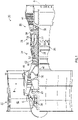
- FIG. 1 schematically illustrates a gas turbine engine 20.
- the gas turbine engine 20 is disclosed herein as a two-spool turbofan that generally incorporates a fan section 22, a compressor section 24, a combustor section 26 and a turbine section 28.
- Alternative engines might include other systems or features.
- the fan section 22 drives air along a bypass flow path B in a bypass duct, while the compressor section 24 drives air along a core flow path C for compression and communication into the combustor section 26 then expansion through the turbine section 28.
- the exemplary engine 20 generally includes a low speed spool 30 and a high speed spool 32 mounted for rotation about an engine central longitudinal axis A relative to an engine static structure 36 via several bearing systems 38. It should be understood that various bearing systems 38 at various locations may alternatively or additionally be provided, and the location of bearing systems 38 may be varied as appropriate to the application.
- the low speed spool 30 generally includes an inner shaft 40 that interconnects a fan 42, a low pressure compressor 44 and a low pressure turbine 46.
- the inner shaft 40 is connected to the fan 42.
- the high speed spool 32 includes an outer shaft 50 that interconnects a high pressure compressor 52 and high pressure turbine 54.
- a combustor 56 is arranged in exemplary gas turbine 20 between the high pressure compressor 52 and the high pressure turbine 54.
- An engine static structure 36 is arranged generally between the high pressure turbine 54 and the low pressure turbine 46.
- the engine static structure 36 further supports bearing systems 38 in the turbine section 28.
- the inner shaft 40 and the outer shaft 50 are concentric and rotate via bearing systems 38 about the engine central longitudinal axis A which is collinear with their longitudinal axes.
- the core airflow is compressed by the low pressure compressor 44 then the high pressure compressor 52, mixed and burned with fuel in the combustor 56, then expanded over the high pressure turbine 54 and low pressure turbine 46.
- the turbines 46, 54 rotationally drive the respective low speed spool 30 and high speed spool 32 in response to the expansion. It will be appreciated that each of the positions of the fan section 22, compressor section 24, combustor section 26, and turbine section 28 may be varied.
- the engine 20 also includes one or more variable area vane assemblies; e.g., vane assemblies 60, 62, etc.
- the vane assemblies direct gas for a respective engine section.
- vane assembly 60 guides and/or adjusts the flow of the core air into the compressor section 24.
- Vane assembly 62 guides and/or adjusts the flow of the core air through the HPC section 24; e.g., between adjacent HPC rotor stages.
- each assembly includes one or more adjustable stator vanes that are arranged circumferentially around the central axis. Each of the stator vanes may be rotated about its respective axis by pivoting a respective vane arm assembly 100 with an actuator (not shown).
- the vane arm assembly 100 is illustrated in greater detail.
- the vane arm assembly includes a vane arm 102.
- the vane arm 102 is operatively coupled to the actuator with a pin 104 proximate a first end 106 of the vane arm 102.
- the pin is part of, or operatively coupled to, a synchronization ring 108 that synchronizes the movement of a plurality of circumferentially spaced stator vanes 110 ( FIG. 2 ).
- the vane arm 102 is coupled to a vane stem 111 of one of the stator vanes 110 proximate a second end 112 of the vane arm 102.
- FIG. 3 shows a single stator vane and vane arm, but it is to be appreciated that some or all of the additional stator vanes may include the features described herein.
- a single stator vane 110 and a single vane arm 102 are described herein.
- the stator vane 110 is disposed within a main flow gaspath 114 to adjust the gas flow therethrough.
- the vane stem 111 extends radially outwardly from the main portion of the stator vane 110 through a port 116 of a case 118 that at least partially defines the main flow gaspath 114.
- the port 116 is defined by a port wall 120 and has a circular cross-section in some embodiments.
- a bushing 122 is disposed at least partially within the port 116.
- the stator vane 110 is referred to as a "buttonless" stator vane. This term describes a vane that does not include a structural feature that engages the case 118.
- the structural feature which may be referred to as a button impedes, or fully blocks, main flow gaspath gas from readily escaping the main flow gaspath to enter a plenum or engine bay that is located radially outward of the case 118.
- the buttonless stator vane 110 disclosed herein results in a clearance 124 between the vane stem 111 and a surrounding structure (e.g., port wall 120, bushing 122, etc.).
- the clearance 124 fluidly couples the main flow gaspath 114 and the engine bay via redirection by the vane arm 102, as described herein.
- the gas naturally tends to flow through the clearance 124 due to the pressure differential between the main flow gaspath 114 (i.e., high) and the engine bay (i.e., lower).
- the gas escaping through the clearance 124 is effectively a jet of gas flowing radially outwardly.
- the vane arm 102 is shaped or contoured to direct the gas toward a structural component that is to be thermally effected by the hot gas leaving the main flow gaspath 114.
- the vane arm 102 includes one or more channels 126 that are formed therein to effect the desired redirection and may have an outer surface that is curved to effect the desired redirection .
- the gas is redirected to contact the synchronization ring 108.
- the synchronization ring 108 is axially aligned with a portion of the case 118 that protrudes radially outward. This portion of the case 118 is referred to as a bumper pad 128.
- the synchronization ring 108 is radially spaced from the bumper pad 128 to define a gap 130.
- the gap 130 is designed to accommodate a maximum relative deflection of the synchronization ring 108 and the bumper pad 128 that occurs due to a temperature difference between the synchronization ring 108 and the bumper pad 128.
- the larger temperature difference that occurs during operation requires a larger gap between the synchronization ring 108 and the bumper pad 128.
- the larger gap that is required inherently reduces the achievable accuracy of the synchronization ring 108 which is the largest contributor to variable vane positional error.
- the redirected gas that is flowed into contact with the synchronization ring 108 reduces the temperature difference between the synchronization ring 108 and the case 118 since the temperature of the synchronization ring 108 is being directly influenced by the temperature of the gas being extracted directly from the main flow gaspath 114. This allows a reduction in the necessary design gap, thereby improving the accuracy at both the worst case condition (i.e., maximum temperature difference), as well as all other thermal conditions.
Landscapes
- Engineering & Computer Science (AREA)
- Mechanical Engineering (AREA)
- General Engineering & Computer Science (AREA)
- Chemical & Material Sciences (AREA)
- Combustion & Propulsion (AREA)
- Physics & Mathematics (AREA)
- Fluid Mechanics (AREA)
- Structures Of Non-Positive Displacement Pumps (AREA)
Description
- The present invention pertains to the art of gas turbine engines and, more particularly, to a thermally compensate synchronization ring of a variable stator vane assembly.
- Some turbine engines include a plurality of engine sections such as, for example, a fan section, a compressor section, a combustor section and a turbine section. The turbine engine may also include a variable area vane arrangement. Such a vane arrangement may be configured to guide and/or adjust the flow of gas into a respective one of the engine sections. Alternatively, the vane arrangement may be configured to guide and/or adjust the flow of gas between adjacent stages of a respective one of the engine sections. Some variable area vane arrangements include a plurality of adjustable stator vanes that are rotatably connected to an inner and outer vane platforms, or engine casing walls. Each of the stator vanes may be rotated about a respective axis using a vane arm. A vane arm may be a sheet metal or machined piece that transmits load from a synchronizing ring to a variable vane stem.
- Variable vane accuracy is a challenge that directly impacts the stall margin of an engine's fan and compressor. Accuracy is directly impacted by thermal differences between an actuation system's synchronization ring and the case it is mounted on because these thermal differences impact the positioning of the synchronization ring. Active thermal compensation solutions are typically avoided due to the significant weight impact.
-
US 2012/0076641 A1 discloses a variable vane assembly including a synchronizing ring, a plurality of attachment studs secured to the synchronizing ring and a plurality of lever arms attached to the vanes at one end and rotational attachment devices configured to rotatably couple the second end of each lever arm to one of the attachment studs. - According to a first aspect of the invention a variable vane assembly is provided as described by claim 1.
- The variable stator vane may be a buttonless stator vane.
- The gas redirected to the synchronization ring may reduce a temperature difference between the synchronization ring and the case.
- The case may comprise a bumper pad extending radially outwardly from the case, the synchronization ring axially aligned with the bumper pad.
- The variable vane assembly may include a bushing disposed within the port of the case.
- The bushing may be press fit to the port wall.
- The case may at least partially define a main flow gaspath.
- The synchronization ring may be radially spaced from the case to define a gap therebetween.
- The variable vane assembly may include a plurality of variable stator vanes disposed in the main flow gaspath and circumferentially spaced from each other.
- The variable vane assembly may include a plurality of said vane arms, each of the vane arms operatively coupled to the synchronization ring and to one of the plurality of variable stator vanes, each of the variable stator vanes having a vane stem extending through a port of the case, the port defined by a port wall, a clearance defined by the vane stem and a port wall to allow gas from the main flow gaspath to pass therethrough.
- The vane arm may be shaped to redirect gas from the main flow gaspath to the synchronization ring.
- According to a second aspect of the invention a gas turbine engine is provided as described by claim 12.
- The gas redirected to the synchronization ring may reduce a temperature difference between the synchronization ring and the case.
- The variable vane assembly may be located proximate an inlet of the compressor section.
- The following descriptions are provided by way of example only and should not be considered limiting in any way. With reference to the accompanying drawings, like elements are numbered alike:
-
FIG. 1 is a side, partial cross-sectional view of a gas turbine engine; -
FIG. 2 is a perspective view of a variable vane assembly of the gas turbine engine; and -
FIG. 3 is a cross-sectional view of a vane arm assembly of the variable vane assembly. - A detailed description of one or more embodiments of the disclosed apparatus and method are presented herein by way of exemplification and not limitation with reference to the Figures.
-
FIG. 1 schematically illustrates agas turbine engine 20. Thegas turbine engine 20 is disclosed herein as a two-spool turbofan that generally incorporates afan section 22, acompressor section 24, acombustor section 26 and aturbine section 28. Alternative engines might include other systems or features. Thefan section 22 drives air along a bypass flow path B in a bypass duct, while thecompressor section 24 drives air along a core flow path C for compression and communication into thecombustor section 26 then expansion through theturbine section 28. - The
exemplary engine 20 generally includes alow speed spool 30 and ahigh speed spool 32 mounted for rotation about an engine central longitudinal axis A relative to an enginestatic structure 36 viaseveral bearing systems 38. It should be understood thatvarious bearing systems 38 at various locations may alternatively or additionally be provided, and the location ofbearing systems 38 may be varied as appropriate to the application. Thelow speed spool 30 generally includes aninner shaft 40 that interconnects afan 42, alow pressure compressor 44 and alow pressure turbine 46. Theinner shaft 40 is connected to thefan 42. Thehigh speed spool 32 includes anouter shaft 50 that interconnects ahigh pressure compressor 52 andhigh pressure turbine 54. Acombustor 56 is arranged inexemplary gas turbine 20 between thehigh pressure compressor 52 and thehigh pressure turbine 54. An enginestatic structure 36 is arranged generally between thehigh pressure turbine 54 and thelow pressure turbine 46. The enginestatic structure 36 further supports bearingsystems 38 in theturbine section 28. Theinner shaft 40 and theouter shaft 50 are concentric and rotate viabearing systems 38 about the engine central longitudinal axis A which is collinear with their longitudinal axes. - The core airflow is compressed by the
low pressure compressor 44 then thehigh pressure compressor 52, mixed and burned with fuel in thecombustor 56, then expanded over thehigh pressure turbine 54 andlow pressure turbine 46. Theturbines low speed spool 30 andhigh speed spool 32 in response to the expansion. It will be appreciated that each of the positions of thefan section 22,compressor section 24,combustor section 26, andturbine section 28 may be varied. - With continued reference to
FIG. 1 , theengine 20 also includes one or more variable area vane assemblies; e.g.,vane assemblies vane assembly 60 guides and/or adjusts the flow of the core air into thecompressor section 24.Vane assembly 62 guides and/or adjusts the flow of the core air through theHPC section 24; e.g., between adjacent HPC rotor stages. - Referring now to
FIG. 2 , threevane assemblies vane arm assembly 100 with an actuator (not shown). - Referring to
FIG. 3 , thevane arm assembly 100 is illustrated in greater detail. The vane arm assembly includes avane arm 102. Thevane arm 102 is operatively coupled to the actuator with apin 104 proximate afirst end 106 of thevane arm 102. The pin is part of, or operatively coupled to, asynchronization ring 108 that synchronizes the movement of a plurality of circumferentially spaced stator vanes 110 (FIG. 2 ). Thevane arm 102 is coupled to avane stem 111 of one of the stator vanes 110 proximate asecond end 112 of thevane arm 102. -
FIG. 3 shows a single stator vane and vane arm, but it is to be appreciated that some or all of the additional stator vanes may include the features described herein. For brevity of discussion, asingle stator vane 110 and asingle vane arm 102 are described herein. As shown, thestator vane 110 is disposed within amain flow gaspath 114 to adjust the gas flow therethrough. The vane stem 111 extends radially outwardly from the main portion of thestator vane 110 through aport 116 of acase 118 that at least partially defines themain flow gaspath 114. Theport 116 is defined by aport wall 120 and has a circular cross-section in some embodiments. Abushing 122 is disposed at least partially within theport 116. - The
stator vane 110 is referred to as a "buttonless" stator vane. This term describes a vane that does not include a structural feature that engages thecase 118. The structural feature, which may be referred to as a button impedes, or fully blocks, main flow gaspath gas from readily escaping the main flow gaspath to enter a plenum or engine bay that is located radially outward of thecase 118. Thebuttonless stator vane 110 disclosed herein results in aclearance 124 between thevane stem 111 and a surrounding structure (e.g.,port wall 120,bushing 122, etc.). Theclearance 124 fluidly couples themain flow gaspath 114 and the engine bay via redirection by thevane arm 102, as described herein. The gas naturally tends to flow through theclearance 124 due to the pressure differential between the main flow gaspath 114 (i.e., high) and the engine bay (i.e., lower). - The gas escaping through the
clearance 124 is effectively a jet of gas flowing radially outwardly. To redirect the jet of gas, thevane arm 102 is shaped or contoured to direct the gas toward a structural component that is to be thermally effected by the hot gas leaving themain flow gaspath 114. Thevane arm 102 includes one ormore channels 126 that are formed therein to effect the desired redirection and may have an outer surface that is curved to effect the desired redirection . - In the illustrated embodiment, the gas is redirected to contact the
synchronization ring 108. Thesynchronization ring 108 is axially aligned with a portion of thecase 118 that protrudes radially outward. This portion of thecase 118 is referred to as abumper pad 128. Thesynchronization ring 108 is radially spaced from thebumper pad 128 to define agap 130. Thegap 130 is designed to accommodate a maximum relative deflection of thesynchronization ring 108 and thebumper pad 128 that occurs due to a temperature difference between thesynchronization ring 108 and thebumper pad 128. The larger temperature difference that occurs during operation requires a larger gap between thesynchronization ring 108 and thebumper pad 128. The larger gap that is required inherently reduces the achievable accuracy of thesynchronization ring 108 which is the largest contributor to variable vane positional error. - In operation, the redirected gas that is flowed into contact with the
synchronization ring 108 reduces the temperature difference between thesynchronization ring 108 and thecase 118 since the temperature of thesynchronization ring 108 is being directly influenced by the temperature of the gas being extracted directly from themain flow gaspath 114. This allows a reduction in the necessary design gap, thereby improving the accuracy at both the worst case condition (i.e., maximum temperature difference), as well as all other thermal conditions. - The term "about" is intended to include the degree of error associated with measurement of the particular quantity based upon the equipment available at the time of filing the application. For example, "about" can include a range of ± 8% or 5%, or 2% of a given value.
- The terminology used herein is for the purpose of describing particular embodiments only and is not intended to be limiting of the present disclosure. As used herein, the singular forms "a", "an" and "the" are intended to include the plural forms as well, unless the context clearly indicates otherwise. It will be further understood that the terms "comprises" and/or "comprising," when used in this specification, specify the presence of stated features, integers, steps, operations, elements, and/or components, but do not preclude the presence or addition of one or more other features, integers, steps, operations, element components, and/or groups thereof.
- While the present invention has been described with reference to an exemplary embodiment or embodiments, it will be understood by those skilled in the art that various changes may be made and equivalents may be substituted for elements thereof without departing from the scope of the present invention as defined by the appended claims.
- Therefore, it is intended that the present invention not be limited to the particular embodiment disclosed as the best mode contemplated for carrying out this present disclosure, but that the present invention will include all embodiments falling within the scope of the claims.
Claims (14)
- A variable vane assembly (60; 62; 64) comprising:a variable stator vane (110) disposed in a main flow gaspath (114), the variable stator vane having a vane stem (111);a case (118) located at a radially outward location of the variable stator vane, the vane stem extending through a port (116) of the case, the port defined by a port wall (120);a synchronization ring (108) spaced from the case to define a gap (130); anda vane arm (102) operatively coupled to a synchronization ring and to the vane stem,characterized by: a clearance (124) defined by the vane stem and a port wall to allow gas from the main flow gaspath to pass therethrough; the vane arm redirecting gas from the main flow gaspath to the synchronization ring, and the vane arm (102) comprising at least one channel (126) to redirect gas from the main flow gaspath (114) to the synchronization ring (108).
- The variable vane assembly (60; 62; 64) of claim 1, wherein the vane arm (102) is shaped to redirect gas from the main flow gaspath (114) to the synchronization ring (108).
- The variable vane assembly (60; 62; 64) of claim 1 or 2, wherein the variable stator vane (110) is a buttonless stator vane.
- The variable vane assembly (60; 62; 64) of any preceding claim, wherein the gas redirected to the synchronization ring (108) reduces a temperature difference between the synchronization ring and the case (118).
- The variable vane assembly (60; 62; 64) of any preceding claim, the case (118) comprising a bumper pad (128) extending radially outwardly from the case, the synchronization ring (108) axially aligned with the bumper pad.
- The variable vane assembly (60; 62; 64) of any preceding claim, further comprising a bushing (122) disposed within the port (116) of the case (118).
- The variable vane assembly (60; 62; 64) of claim 6, wherein the bushing (122) is press fit to the port wall (120).
- The variable vane assembly (60; 62; 64) of any preceding claim wherein the case (118) at least partially defines a main flow gaspath (114).
- The variable vane assembly (60; 62; 64) of any preceding claim wherein the synchronization ring (108) is radially spaced from the case to define the gap (130) therebetween.
- The variable vane assembly (60; 62; 64) of any preceding claim wherein the variable vane assembly comprises a plurality of variable stator vanes (110) disposed in the main flow gaspath and circumferentially spaced from each other.
- The variable vane assembly (60; 62; 64) of claim 10, further comprising:
a plurality of said vane arms (102), each of the vane arms operatively coupled to the synchronization ring (108) and to one of the plurality of variable stator vanes (110), each of the variable stator vanes having a vane stem (111) extending through a port of the case (116), the port defined by a port wall (120), a clearance (124) defined by the vane stem and a port wall to allow gas from the main flow gaspath to pass therethrough. - A gas turbine engine (20) comprising:a compressor section (24);a combustor section (26);a turbine section (28); anda variable vane assembly (60; 62; 64) as claimed in any preceding claim.
- The gas turbine engine (20) of claim 12, wherein the gas redirected to the synchronization ring (108) reduces a temperature difference between the synchronization ring and the case (118).
- The gas turbine engine (20) of claim 12 or 13, wherein the variable vane assembly (60; 62; 64) is located proximate an inlet of the compressor section (24).
Applications Claiming Priority (1)
| Application Number | Priority Date | Filing Date | Title |
|---|---|---|---|
| US16/252,976 US11002142B2 (en) | 2019-01-21 | 2019-01-21 | Thermally compensated synchronization ring of a variable stator vane assembly |
Publications (2)
| Publication Number | Publication Date |
|---|---|
| EP3683409A1 EP3683409A1 (en) | 2020-07-22 |
| EP3683409B1 true EP3683409B1 (en) | 2022-07-13 |
Family
ID=68653401
Family Applications (1)
| Application Number | Title | Priority Date | Filing Date |
|---|---|---|---|
| EP19210738.1A Active EP3683409B1 (en) | 2019-01-21 | 2019-11-21 | Thermally compensated synchronization ring of a variable stator vane assembly |
Country Status (2)
| Country | Link |
|---|---|
| US (1) | US11002142B2 (en) |
| EP (1) | EP3683409B1 (en) |
Family Cites Families (8)
| Publication number | Priority date | Publication date | Assignee | Title |
|---|---|---|---|---|
| US5622473A (en) | 1995-11-17 | 1997-04-22 | General Electric Company | Variable stator vane assembly |
| US5601401A (en) | 1995-12-21 | 1997-02-11 | United Technologies Corporation | Variable stage vane actuating apparatus |
| US7413401B2 (en) | 2006-01-17 | 2008-08-19 | General Electric Company | Methods and apparatus for controlling variable stator vanes |
| US8297918B2 (en) * | 2009-01-06 | 2012-10-30 | General Electric Company | Variable position guide vane actuation system and method |
| US8714916B2 (en) | 2010-09-28 | 2014-05-06 | General Electric Company | Variable vane assembly for a turbine compressor |
| US9988926B2 (en) | 2013-03-13 | 2018-06-05 | United Technologies Corporation | Machined vane arm of a variable vane actuation system |
| EP2787182B1 (en) * | 2013-04-02 | 2018-06-06 | MTU Aero Engines AG | Guide blade for a fluid flow engine, guide blade grid and method for the production of a guide blade or a guide blade grid |
| US10227888B2 (en) * | 2015-02-16 | 2019-03-12 | United Technologies Corporation | Variable vane systems |
-
2019
- 2019-01-21 US US16/252,976 patent/US11002142B2/en active Active
- 2019-11-21 EP EP19210738.1A patent/EP3683409B1/en active Active
Also Published As
| Publication number | Publication date |
|---|---|
| EP3683409A1 (en) | 2020-07-22 |
| US20200232335A1 (en) | 2020-07-23 |
| US11002142B2 (en) | 2021-05-11 |
Similar Documents
| Publication | Publication Date | Title |
|---|---|---|
| EP4239166B1 (en) | Seal assembly for a gas turbine engine and corresponding method of sealing | |
| EP2964960B1 (en) | Gas turbine engine centrifugal compressor with seal between two diffuser parts | |
| EP3862539B1 (en) | Flow diverter for mid-turbine frame cooling air delivery | |
| EP3144479A1 (en) | Stator component cooling | |
| US20170204734A1 (en) | Cooled CMC Wall Contouring | |
| EP3533973B1 (en) | Self-retaining vane arm assembly for gas turbine engine | |
| JP5491693B2 (en) | Equipment that facilitates loss reduction in turbine engines | |
| EP2948642B1 (en) | Multi-segment adjustable stator vane for a variable area vane arrangement | |
| US10221767B2 (en) | Actively cooled blade outer air seal | |
| EP3012405A2 (en) | Coolant flow redirection component | |
| EP3073061A1 (en) | System for cooling a turbine shroud | |
| US10495107B2 (en) | Guide vane assembly with compensation device | |
| EP3633153B1 (en) | Bell crank and bar assembly | |
| EP3047111B1 (en) | Component for a gas turbine engine, corresponding gas turbine engine and method of cooling | |
| US20160258306A1 (en) | Baffle inserts | |
| US10563539B2 (en) | Turbine engine with bearing assembly | |
| EP3715655B1 (en) | Bearing assembly | |
| US11002142B2 (en) | Thermally compensated synchronization ring of a variable stator vane assembly | |
| EP2946081B1 (en) | Variable area vane arrangement for a turbine engine | |
| EP3623581B1 (en) | Integral vane stage | |
| EP4328419B1 (en) | Exhaust assembly for purging a nacelle cavity of a propulsion system | |
| CN114144573B (en) | Turbomachinery rectifier stage with cooling air leakage channel having a variable cross section depending on the orientation of the blades | |
| EP4613980A1 (en) | Turbine vane with leading edge cooling | |
| EP3502417B1 (en) | Platform flow turning elements for gas turbine engine components | |
| EP3067521B1 (en) | Turbine vane with baffles having tolerance resistance coverplates |
Legal Events
| Date | Code | Title | Description |
|---|---|---|---|
| PUAI | Public reference made under article 153(3) epc to a published international application that has entered the european phase |
Free format text: ORIGINAL CODE: 0009012 |
|
| STAA | Information on the status of an ep patent application or granted ep patent |
Free format text: STATUS: THE APPLICATION HAS BEEN PUBLISHED |
|
| AK | Designated contracting states |
Kind code of ref document: A1 Designated state(s): AL AT BE BG CH CY CZ DE DK EE ES FI FR GB GR HR HU IE IS IT LI LT LU LV MC MK MT NL NO PL PT RO RS SE SI SK SM TR |
|
| AX | Request for extension of the european patent |
Extension state: BA ME |
|
| STAA | Information on the status of an ep patent application or granted ep patent |
Free format text: STATUS: REQUEST FOR EXAMINATION WAS MADE |
|
| 17P | Request for examination filed |
Effective date: 20210122 |
|
| RBV | Designated contracting states (corrected) |
Designated state(s): AL AT BE BG CH CY CZ DE DK EE ES FI FR GB GR HR HU IE IS IT LI LT LU LV MC MK MT NL NO PL PT RO RS SE SI SK SM TR |
|
| RAP1 | Party data changed (applicant data changed or rights of an application transferred) |
Owner name: RAYTHEON TECHNOLOGIES CORPORATION |
|
| GRAP | Despatch of communication of intention to grant a patent |
Free format text: ORIGINAL CODE: EPIDOSNIGR1 |
|
| STAA | Information on the status of an ep patent application or granted ep patent |
Free format text: STATUS: GRANT OF PATENT IS INTENDED |
|
| INTG | Intention to grant announced |
Effective date: 20220201 |
|
| GRAS | Grant fee paid |
Free format text: ORIGINAL CODE: EPIDOSNIGR3 |
|
| GRAA | (expected) grant |
Free format text: ORIGINAL CODE: 0009210 |
|
| STAA | Information on the status of an ep patent application or granted ep patent |
Free format text: STATUS: THE PATENT HAS BEEN GRANTED |
|
| AK | Designated contracting states |
Kind code of ref document: B1 Designated state(s): AL AT BE BG CH CY CZ DE DK EE ES FI FR GB GR HR HU IE IS IT LI LT LU LV MC MK MT NL NO PL PT RO RS SE SI SK SM TR |
|
| REG | Reference to a national code |
Ref country code: CH Ref legal event code: EP |
|
| REG | Reference to a national code |
Ref country code: DE Ref legal event code: R096 Ref document number: 602019016935 Country of ref document: DE |
|
| REG | Reference to a national code |
Ref country code: AT Ref legal event code: REF Ref document number: 1504400 Country of ref document: AT Kind code of ref document: T Effective date: 20220815 |
|
| REG | Reference to a national code |
Ref country code: IE Ref legal event code: FG4D |
|
| REG | Reference to a national code |
Ref country code: LT Ref legal event code: MG9D |
|
| REG | Reference to a national code |
Ref country code: NL Ref legal event code: MP Effective date: 20220713 |
|
| PG25 | Lapsed in a contracting state [announced via postgrant information from national office to epo] |
Ref country code: SE Free format text: LAPSE BECAUSE OF FAILURE TO SUBMIT A TRANSLATION OF THE DESCRIPTION OR TO PAY THE FEE WITHIN THE PRESCRIBED TIME-LIMIT Effective date: 20220713 Ref country code: RS Free format text: LAPSE BECAUSE OF FAILURE TO SUBMIT A TRANSLATION OF THE DESCRIPTION OR TO PAY THE FEE WITHIN THE PRESCRIBED TIME-LIMIT Effective date: 20220713 Ref country code: PT Free format text: LAPSE BECAUSE OF FAILURE TO SUBMIT A TRANSLATION OF THE DESCRIPTION OR TO PAY THE FEE WITHIN THE PRESCRIBED TIME-LIMIT Effective date: 20221114 Ref country code: NO Free format text: LAPSE BECAUSE OF FAILURE TO SUBMIT A TRANSLATION OF THE DESCRIPTION OR TO PAY THE FEE WITHIN THE PRESCRIBED TIME-LIMIT Effective date: 20221013 Ref country code: NL Free format text: LAPSE BECAUSE OF FAILURE TO SUBMIT A TRANSLATION OF THE DESCRIPTION OR TO PAY THE FEE WITHIN THE PRESCRIBED TIME-LIMIT Effective date: 20220713 Ref country code: LV Free format text: LAPSE BECAUSE OF FAILURE TO SUBMIT A TRANSLATION OF THE DESCRIPTION OR TO PAY THE FEE WITHIN THE PRESCRIBED TIME-LIMIT Effective date: 20220713 Ref country code: LT Free format text: LAPSE BECAUSE OF FAILURE TO SUBMIT A TRANSLATION OF THE DESCRIPTION OR TO PAY THE FEE WITHIN THE PRESCRIBED TIME-LIMIT Effective date: 20220713 Ref country code: FI Free format text: LAPSE BECAUSE OF FAILURE TO SUBMIT A TRANSLATION OF THE DESCRIPTION OR TO PAY THE FEE WITHIN THE PRESCRIBED TIME-LIMIT Effective date: 20220713 Ref country code: ES Free format text: LAPSE BECAUSE OF FAILURE TO SUBMIT A TRANSLATION OF THE DESCRIPTION OR TO PAY THE FEE WITHIN THE PRESCRIBED TIME-LIMIT Effective date: 20220713 |
|
| REG | Reference to a national code |
Ref country code: AT Ref legal event code: MK05 Ref document number: 1504400 Country of ref document: AT Kind code of ref document: T Effective date: 20220713 |
|
| PG25 | Lapsed in a contracting state [announced via postgrant information from national office to epo] |
Ref country code: PL Free format text: LAPSE BECAUSE OF FAILURE TO SUBMIT A TRANSLATION OF THE DESCRIPTION OR TO PAY THE FEE WITHIN THE PRESCRIBED TIME-LIMIT Effective date: 20220713 Ref country code: IS Free format text: LAPSE BECAUSE OF FAILURE TO SUBMIT A TRANSLATION OF THE DESCRIPTION OR TO PAY THE FEE WITHIN THE PRESCRIBED TIME-LIMIT Effective date: 20221113 Ref country code: HR Free format text: LAPSE BECAUSE OF FAILURE TO SUBMIT A TRANSLATION OF THE DESCRIPTION OR TO PAY THE FEE WITHIN THE PRESCRIBED TIME-LIMIT Effective date: 20220713 Ref country code: GR Free format text: LAPSE BECAUSE OF FAILURE TO SUBMIT A TRANSLATION OF THE DESCRIPTION OR TO PAY THE FEE WITHIN THE PRESCRIBED TIME-LIMIT Effective date: 20221014 |
|
| REG | Reference to a national code |
Ref country code: DE Ref legal event code: R097 Ref document number: 602019016935 Country of ref document: DE |
|
| PG25 | Lapsed in a contracting state [announced via postgrant information from national office to epo] |
Ref country code: SM Free format text: LAPSE BECAUSE OF FAILURE TO SUBMIT A TRANSLATION OF THE DESCRIPTION OR TO PAY THE FEE WITHIN THE PRESCRIBED TIME-LIMIT Effective date: 20220713 Ref country code: RO Free format text: LAPSE BECAUSE OF FAILURE TO SUBMIT A TRANSLATION OF THE DESCRIPTION OR TO PAY THE FEE WITHIN THE PRESCRIBED TIME-LIMIT Effective date: 20220713 Ref country code: DK Free format text: LAPSE BECAUSE OF FAILURE TO SUBMIT A TRANSLATION OF THE DESCRIPTION OR TO PAY THE FEE WITHIN THE PRESCRIBED TIME-LIMIT Effective date: 20220713 Ref country code: CZ Free format text: LAPSE BECAUSE OF FAILURE TO SUBMIT A TRANSLATION OF THE DESCRIPTION OR TO PAY THE FEE WITHIN THE PRESCRIBED TIME-LIMIT Effective date: 20220713 Ref country code: AT Free format text: LAPSE BECAUSE OF FAILURE TO SUBMIT A TRANSLATION OF THE DESCRIPTION OR TO PAY THE FEE WITHIN THE PRESCRIBED TIME-LIMIT Effective date: 20220713 |
|
| PLBE | No opposition filed within time limit |
Free format text: ORIGINAL CODE: 0009261 |
|
| STAA | Information on the status of an ep patent application or granted ep patent |
Free format text: STATUS: NO OPPOSITION FILED WITHIN TIME LIMIT |
|
| PG25 | Lapsed in a contracting state [announced via postgrant information from national office to epo] |
Ref country code: SK Free format text: LAPSE BECAUSE OF FAILURE TO SUBMIT A TRANSLATION OF THE DESCRIPTION OR TO PAY THE FEE WITHIN THE PRESCRIBED TIME-LIMIT Effective date: 20220713 Ref country code: EE Free format text: LAPSE BECAUSE OF FAILURE TO SUBMIT A TRANSLATION OF THE DESCRIPTION OR TO PAY THE FEE WITHIN THE PRESCRIBED TIME-LIMIT Effective date: 20220713 |
|
| 26N | No opposition filed |
Effective date: 20230414 |
|
| P01 | Opt-out of the competence of the unified patent court (upc) registered |
Effective date: 20230521 |
|
| PG25 | Lapsed in a contracting state [announced via postgrant information from national office to epo] |
Ref country code: MC Free format text: LAPSE BECAUSE OF FAILURE TO SUBMIT A TRANSLATION OF THE DESCRIPTION OR TO PAY THE FEE WITHIN THE PRESCRIBED TIME-LIMIT Effective date: 20220713 Ref country code: AL Free format text: LAPSE BECAUSE OF FAILURE TO SUBMIT A TRANSLATION OF THE DESCRIPTION OR TO PAY THE FEE WITHIN THE PRESCRIBED TIME-LIMIT Effective date: 20220713 |
|
| REG | Reference to a national code |
Ref country code: CH Ref legal event code: PL |
|
| REG | Reference to a national code |
Ref country code: BE Ref legal event code: MM Effective date: 20221130 |
|
| PG25 | Lapsed in a contracting state [announced via postgrant information from national office to epo] |
Ref country code: LI Free format text: LAPSE BECAUSE OF NON-PAYMENT OF DUE FEES Effective date: 20221130 Ref country code: CH Free format text: LAPSE BECAUSE OF NON-PAYMENT OF DUE FEES Effective date: 20221130 |
|
| PG25 | Lapsed in a contracting state [announced via postgrant information from national office to epo] |
Ref country code: SI Free format text: LAPSE BECAUSE OF FAILURE TO SUBMIT A TRANSLATION OF THE DESCRIPTION OR TO PAY THE FEE WITHIN THE PRESCRIBED TIME-LIMIT Effective date: 20220713 Ref country code: LU Free format text: LAPSE BECAUSE OF NON-PAYMENT OF DUE FEES Effective date: 20221121 |
|
| PG25 | Lapsed in a contracting state [announced via postgrant information from national office to epo] |
Ref country code: IE Free format text: LAPSE BECAUSE OF NON-PAYMENT OF DUE FEES Effective date: 20221121 |
|
| PG25 | Lapsed in a contracting state [announced via postgrant information from national office to epo] |
Ref country code: BE Free format text: LAPSE BECAUSE OF NON-PAYMENT OF DUE FEES Effective date: 20221130 |
|
| PG25 | Lapsed in a contracting state [announced via postgrant information from national office to epo] |
Ref country code: IT Free format text: LAPSE BECAUSE OF FAILURE TO SUBMIT A TRANSLATION OF THE DESCRIPTION OR TO PAY THE FEE WITHIN THE PRESCRIBED TIME-LIMIT Effective date: 20220713 |
|
| PG25 | Lapsed in a contracting state [announced via postgrant information from national office to epo] |
Ref country code: HU Free format text: LAPSE BECAUSE OF FAILURE TO SUBMIT A TRANSLATION OF THE DESCRIPTION OR TO PAY THE FEE WITHIN THE PRESCRIBED TIME-LIMIT; INVALID AB INITIO Effective date: 20191121 |
|
| PG25 | Lapsed in a contracting state [announced via postgrant information from national office to epo] |
Ref country code: CY Free format text: LAPSE BECAUSE OF FAILURE TO SUBMIT A TRANSLATION OF THE DESCRIPTION OR TO PAY THE FEE WITHIN THE PRESCRIBED TIME-LIMIT Effective date: 20220713 |
|
| PG25 | Lapsed in a contracting state [announced via postgrant information from national office to epo] |
Ref country code: MK Free format text: LAPSE BECAUSE OF FAILURE TO SUBMIT A TRANSLATION OF THE DESCRIPTION OR TO PAY THE FEE WITHIN THE PRESCRIBED TIME-LIMIT Effective date: 20220713 |
|
| PG25 | Lapsed in a contracting state [announced via postgrant information from national office to epo] |
Ref country code: TR Free format text: LAPSE BECAUSE OF FAILURE TO SUBMIT A TRANSLATION OF THE DESCRIPTION OR TO PAY THE FEE WITHIN THE PRESCRIBED TIME-LIMIT Effective date: 20220713 |
|
| PG25 | Lapsed in a contracting state [announced via postgrant information from national office to epo] |
Ref country code: BG Free format text: LAPSE BECAUSE OF FAILURE TO SUBMIT A TRANSLATION OF THE DESCRIPTION OR TO PAY THE FEE WITHIN THE PRESCRIBED TIME-LIMIT Effective date: 20220713 |
|
| PG25 | Lapsed in a contracting state [announced via postgrant information from national office to epo] |
Ref country code: MT Free format text: LAPSE BECAUSE OF FAILURE TO SUBMIT A TRANSLATION OF THE DESCRIPTION OR TO PAY THE FEE WITHIN THE PRESCRIBED TIME-LIMIT Effective date: 20220713 |
|
| REG | Reference to a national code |
Ref country code: DE Ref legal event code: R081 Ref document number: 602019016935 Country of ref document: DE Owner name: RTX CORPORATION (N.D.GES.D. STAATES DELAWARE),, US Free format text: FORMER OWNER: RAYTHEON TECHNOLOGIES CORPORATION, FARMINGTON, CT, US |
|
| PGFP | Annual fee paid to national office [announced via postgrant information from national office to epo] |
Ref country code: DE Payment date: 20251022 Year of fee payment: 7 |
|
| PGFP | Annual fee paid to national office [announced via postgrant information from national office to epo] |
Ref country code: GB Payment date: 20251023 Year of fee payment: 7 |
|
| PGFP | Annual fee paid to national office [announced via postgrant information from national office to epo] |
Ref country code: FR Payment date: 20251023 Year of fee payment: 7 |