EP3683402A1 - Airfoil with body and cover panel - Google Patents
Airfoil with body and cover panel Download PDFInfo
- Publication number
- EP3683402A1 EP3683402A1 EP20152749.6A EP20152749A EP3683402A1 EP 3683402 A1 EP3683402 A1 EP 3683402A1 EP 20152749 A EP20152749 A EP 20152749A EP 3683402 A1 EP3683402 A1 EP 3683402A1
- Authority
- EP
- European Patent Office
- Prior art keywords
- cover panel
- airfoil
- recited
- node
- tabs
- Prior art date
- Legal status (The legal status is an assumption and is not a legal conclusion. Google has not performed a legal analysis and makes no representation as to the accuracy of the status listed.)
- Granted
Links
Images



Classifications
-
- F—MECHANICAL ENGINEERING; LIGHTING; HEATING; WEAPONS; BLASTING
- F01—MACHINES OR ENGINES IN GENERAL; ENGINE PLANTS IN GENERAL; STEAM ENGINES
- F01D—NON-POSITIVE DISPLACEMENT MACHINES OR ENGINES, e.g. STEAM TURBINES
- F01D5/00—Blades; Blade-carrying members; Heating, heat-insulating, cooling or antivibration means on the blades or the members
- F01D5/12—Blades
- F01D5/14—Form or construction
- F01D5/147—Construction, i.e. structural features, e.g. of weight-saving hollow blades
-
- F—MECHANICAL ENGINEERING; LIGHTING; HEATING; WEAPONS; BLASTING
- F01—MACHINES OR ENGINES IN GENERAL; ENGINE PLANTS IN GENERAL; STEAM ENGINES
- F01D—NON-POSITIVE DISPLACEMENT MACHINES OR ENGINES, e.g. STEAM TURBINES
- F01D5/00—Blades; Blade-carrying members; Heating, heat-insulating, cooling or antivibration means on the blades or the members
- F01D5/12—Blades
- F01D5/14—Form or construction
- F01D5/18—Hollow blades, i.e. blades with cooling or heating channels or cavities; Heating, heat-insulating or cooling means on blades
-
- F—MECHANICAL ENGINEERING; LIGHTING; HEATING; WEAPONS; BLASTING
- F05—INDEXING SCHEMES RELATING TO ENGINES OR PUMPS IN VARIOUS SUBCLASSES OF CLASSES F01-F04
- F05D—INDEXING SCHEME FOR ASPECTS RELATING TO NON-POSITIVE-DISPLACEMENT MACHINES OR ENGINES, GAS-TURBINES OR JET-PROPULSION PLANTS
- F05D2220/00—Application
- F05D2220/30—Application in turbines
- F05D2220/36—Application in turbines specially adapted for the fan of turbofan engines
-
- F—MECHANICAL ENGINEERING; LIGHTING; HEATING; WEAPONS; BLASTING
- F05—INDEXING SCHEMES RELATING TO ENGINES OR PUMPS IN VARIOUS SUBCLASSES OF CLASSES F01-F04
- F05D—INDEXING SCHEME FOR ASPECTS RELATING TO NON-POSITIVE-DISPLACEMENT MACHINES OR ENGINES, GAS-TURBINES OR JET-PROPULSION PLANTS
- F05D2230/00—Manufacture
- F05D2230/60—Assembly methods
- F05D2230/64—Assembly methods using positioning or alignment devices for aligning or centring, e.g. pins
-
- F—MECHANICAL ENGINEERING; LIGHTING; HEATING; WEAPONS; BLASTING
- F05—INDEXING SCHEMES RELATING TO ENGINES OR PUMPS IN VARIOUS SUBCLASSES OF CLASSES F01-F04
- F05D—INDEXING SCHEME FOR ASPECTS RELATING TO NON-POSITIVE-DISPLACEMENT MACHINES OR ENGINES, GAS-TURBINES OR JET-PROPULSION PLANTS
- F05D2240/00—Components
- F05D2240/20—Rotors
- F05D2240/30—Characteristics of rotor blades, i.e. of any element transforming dynamic fluid energy to or from rotational energy and being attached to a rotor
- F05D2240/301—Cross-sectional characteristics
-
- F—MECHANICAL ENGINEERING; LIGHTING; HEATING; WEAPONS; BLASTING
- F05—INDEXING SCHEMES RELATING TO ENGINES OR PUMPS IN VARIOUS SUBCLASSES OF CLASSES F01-F04
- F05D—INDEXING SCHEME FOR ASPECTS RELATING TO NON-POSITIVE-DISPLACEMENT MACHINES OR ENGINES, GAS-TURBINES OR JET-PROPULSION PLANTS
- F05D2250/00—Geometry
- F05D2250/30—Arrangement of components
- F05D2250/33—Arrangement of components symmetrical
-
- F—MECHANICAL ENGINEERING; LIGHTING; HEATING; WEAPONS; BLASTING
- F05—INDEXING SCHEMES RELATING TO ENGINES OR PUMPS IN VARIOUS SUBCLASSES OF CLASSES F01-F04
- F05D—INDEXING SCHEME FOR ASPECTS RELATING TO NON-POSITIVE-DISPLACEMENT MACHINES OR ENGINES, GAS-TURBINES OR JET-PROPULSION PLANTS
- F05D2260/00—Function
- F05D2260/30—Retaining components in desired mutual position
- F05D2260/31—Retaining bolts or nuts
-
- F—MECHANICAL ENGINEERING; LIGHTING; HEATING; WEAPONS; BLASTING
- F05—INDEXING SCHEMES RELATING TO ENGINES OR PUMPS IN VARIOUS SUBCLASSES OF CLASSES F01-F04
- F05D—INDEXING SCHEME FOR ASPECTS RELATING TO NON-POSITIVE-DISPLACEMENT MACHINES OR ENGINES, GAS-TURBINES OR JET-PROPULSION PLANTS
- F05D2300/00—Materials; Properties thereof
- F05D2300/60—Properties or characteristics given to material by treatment or manufacturing
- F05D2300/603—Composites; e.g. fibre-reinforced
-
- F—MECHANICAL ENGINEERING; LIGHTING; HEATING; WEAPONS; BLASTING
- F16—ENGINEERING ELEMENTS AND UNITS; GENERAL MEASURES FOR PRODUCING AND MAINTAINING EFFECTIVE FUNCTIONING OF MACHINES OR INSTALLATIONS; THERMAL INSULATION IN GENERAL
- F16B—DEVICES FOR FASTENING OR SECURING CONSTRUCTIONAL ELEMENTS OR MACHINE PARTS TOGETHER, e.g. NAILS, BOLTS, CIRCLIPS, CLAMPS, CLIPS OR WEDGES; JOINTS OR JOINTING
- F16B13/00—Dowels or other devices fastened in walls or the like by inserting them in holes made therein for that purpose
- F16B13/02—Dowels or other devices fastened in walls or the like by inserting them in holes made therein for that purpose in one piece with protrusions or ridges on the shaft
-
- F—MECHANICAL ENGINEERING; LIGHTING; HEATING; WEAPONS; BLASTING
- F16—ENGINEERING ELEMENTS AND UNITS; GENERAL MEASURES FOR PRODUCING AND MAINTAINING EFFECTIVE FUNCTIONING OF MACHINES OR INSTALLATIONS; THERMAL INSULATION IN GENERAL
- F16B—DEVICES FOR FASTENING OR SECURING CONSTRUCTIONAL ELEMENTS OR MACHINE PARTS TOGETHER, e.g. NAILS, BOLTS, CIRCLIPS, CLAMPS, CLIPS OR WEDGES; JOINTS OR JOINTING
- F16B13/00—Dowels or other devices fastened in walls or the like by inserting them in holes made therein for that purpose
- F16B2013/007—Dowels or other devices fastened in walls or the like by inserting them in holes made therein for that purpose to be fastened in undercut holes
-
- F—MECHANICAL ENGINEERING; LIGHTING; HEATING; WEAPONS; BLASTING
- F16—ENGINEERING ELEMENTS AND UNITS; GENERAL MEASURES FOR PRODUCING AND MAINTAINING EFFECTIVE FUNCTIONING OF MACHINES OR INSTALLATIONS; THERMAL INSULATION IN GENERAL
- F16B—DEVICES FOR FASTENING OR SECURING CONSTRUCTIONAL ELEMENTS OR MACHINE PARTS TOGETHER, e.g. NAILS, BOLTS, CIRCLIPS, CLAMPS, CLIPS OR WEDGES; JOINTS OR JOINTING
- F16B5/00—Joining sheets or plates, e.g. panels, to one another or to strips or bars parallel to them
- F16B5/06—Joining sheets or plates, e.g. panels, to one another or to strips or bars parallel to them by means of clamps or clips
- F16B5/0607—Joining sheets or plates, e.g. panels, to one another or to strips or bars parallel to them by means of clamps or clips joining sheets or plates to each other
- F16B5/0621—Joining sheets or plates, e.g. panels, to one another or to strips or bars parallel to them by means of clamps or clips joining sheets or plates to each other in parallel relationship
- F16B5/0657—Joining sheets or plates, e.g. panels, to one another or to strips or bars parallel to them by means of clamps or clips joining sheets or plates to each other in parallel relationship at least one of the plates providing a raised structure, e.g. of the doghouse type, for connection with the clamps or clips of the other plate
-
- Y—GENERAL TAGGING OF NEW TECHNOLOGICAL DEVELOPMENTS; GENERAL TAGGING OF CROSS-SECTIONAL TECHNOLOGIES SPANNING OVER SEVERAL SECTIONS OF THE IPC; TECHNICAL SUBJECTS COVERED BY FORMER USPC CROSS-REFERENCE ART COLLECTIONS [XRACs] AND DIGESTS
- Y02—TECHNOLOGIES OR APPLICATIONS FOR MITIGATION OR ADAPTATION AGAINST CLIMATE CHANGE
- Y02T—CLIMATE CHANGE MITIGATION TECHNOLOGIES RELATED TO TRANSPORTATION
- Y02T50/00—Aeronautics or air transport
- Y02T50/60—Efficient propulsion technologies, e.g. for aircraft
Definitions
- An airfoil according to an aspect of the present invention includes a body that has rib nodes that define a node cavity therein, and a cover panel carried on the body over the rib nodes.
- the cover panel has tabs that project into the node cavities. Plugs are disposed in the node cavities and pinch the tabs against the node cavities, locking the cover panel on the body.
- each of the plugs includes an exposed surface that is flush with the cover panel.
- Figure 7 illustrates a representative portion of another example airfoil 158 that also includes a body 160 and a cover panel 162.
- like reference numerals designate like elements where appropriate and reference numerals with the addition of one-hundred or multiples thereof designate modified elements that are understood to incorporate the same features and benefits of the corresponding elements.
- the body 160 and cover panel 162 may generally have the same shape as shown in Figure 1 .
- the airfoil 158 employs push fasteners 184 (one shown).
- the push fasteners 184 may be used in the locations where the rib nodes 78 are shown in Figure 1 .
- the push fasteners 184 extend through the cover panel 162 and lock the cover panel 162 on the body 160.
- the surface film layer 188c serves to enhance resistance to wear/erosion.
- the surface film layer 188c may be formed of an elastomer, such as a fluoroelastomer.
- Figure 10 illustrates another example of a push fastener 284.
- the push fastener 284 includes radial flexible barbs 284a and the body 160 includes a straight hole 286.
- the barbs 284a are carried on a shank that extends from the head 284b.
- the barbs 284a is received into the straight hole 286 to secure the cover panel 162 to the body 160.
- the barbs 284a are compressed and deflect or deform.
- the barbs 284a tend to decompress and thus press outwards on the hole 286 to hold the fastener 284, and thus the cover panel 162, in place.
Landscapes
- Engineering & Computer Science (AREA)
- Mechanical Engineering (AREA)
- General Engineering & Computer Science (AREA)
- Architecture (AREA)
- Structures Of Non-Positive Displacement Pumps (AREA)
Abstract
Description
- Airfoils, and particularly fan blades, may be made from multiple pieces in order to reduce weight and ease manufacturing. As an example, a hollow blade may be formed by securing two airfoil shell pieces together to provide an aerodynamic blade shape. An adhesive is used to bond the pieces together. A challenge, however, is that a relatively large amount of surface area is needed to strongly bond the pieces together and provide structural strength to the airfoil. This results in the use of thick interfacial ribs that add weight, thereby undermining the ultimate goal.
- An airfoil according to an aspect of the present invention includes a body that has rib nodes that define a node cavity therein, and a cover panel carried on the body over the rib nodes. The cover panel has tabs that project into the node cavities. Plugs are disposed in the node cavities and pinch the tabs against the node cavities, locking the cover panel on the body.
- In an embodiment, each of the plugs includes an exposed surface that is flush with the cover panel.
- In a further embodiment of any of the foregoing embodiments, each of the rib nodes includes an undercut.
- In a further embodiment of any of the foregoing embodiments, the cover panel includes a plurality of the tabs in each of the node cavities.
- In a further embodiment of any of the foregoing embodiments, the tabs are flaps bent from the cover panel.
- In a further embodiment of any of the foregoing embodiments, the cover panel is a fiber-reinforced polymer composite, and the body is metal.
- In a further embodiment of any of the foregoing embodiments, each of the node cavities is symmetric.
- In a further embodiment of any of the foregoing embodiments, each of the node cavities is round.
- In a further embodiment of any of the foregoing embodiments, the plugs are polymer-based.
- In a further embodiment of any of the foregoing embodiments, the plugs are fiber-reinforced polymer composite.
- In a further embodiment of any of the foregoing embodiments, each of the plugs includes an exposed surface that is flush with the cover panel. Each of the rib nodes includes an undercut. The cover panel includes a plurality of the tabs in each of the node cavities, and the tabs are folds bent from the cover panel.
- An airfoil according to another aspect of the present invention includes a metal body, a cover panel carried on the metal body, and push fasteners that extend through the cover panel and lock the cover panel on the metal body.
- In an embodiment, each of the push fasteners includes flexible barbs.
- In a further embodiment of any of the foregoing embodiments, each of the push fasteners includes a head that is embedded in the cover panel.
- In a further embodiment of any of the foregoing embodiments, the cover panel includes stitching adjacent the head of the push fasteners.
- In a further embodiment of any of the foregoing embodiments, the metal body includes holes receiving the push fasteners, and the holes include undercuts.
- In a further embodiment of any of the foregoing embodiments, the metal body includes straight holes receiving the push fasteners.
- A gas turbine engine according to another aspect of the present invention includes a fan, a compressor section, a combustor in fluid communication with the compressor section, and a turbine section in fluid communication with the combustor. The fan has airfoils according to any of the foregoing examples.
- The various features and advantages of the present disclosure will become apparent to those skilled in the art from the following detailed description. The drawings that accompany the detailed description can be briefly described as follows.
-
Figure 1 illustrates a gas turbine engine. -
Figure 2 illustrates an example airfoil of the gas turbine engine. -
Figure 3 illustrates a magnified view of a portion of the airfoil ofFigure 2 . -
Figure 4 illustrates a sectioned view of a representative portion of the airfoil. -
Figure 5 illustrates a top-down view of a representative portion of the airfoil. -
Figure 6 illustrates a view of flaps cut into an uncured cover panel. -
Figure 7 illustrates an airfoil with a push fastener. -
Figure 8 illustrates a rib that includes a flange and an adhesive layer. -
Figure 9 illustrates an airfoil with a push fastener and stitching. -
Figure 10 illustrates an airfoil with a push fastener and straight hole. -
Figure 11A illustrates a node that defines a node recess, a cover panel that conforms to the node recess, and a fastener that has a head that sits in the node recess. -
Figure 11B is a sectioned view ofFigure 11A . -
Figure 1 schematically illustrates agas turbine engine 20. Thegas turbine engine 20 is disclosed herein as a two-spool turbofan that generally incorporates afan section 22, acompressor section 24, a combustor section 26 and aturbine section 28. Thefan section 22 drives air along a bypass flow path B in a bypass duct defined within anacelle 15, and also drives air along a core flow path C for compression and communication into the combustor section 26 then expansion through theturbine section 28. Although depicted as a two-spool turbofan gas turbine engine in the disclosed non-limiting embodiment, it should be understood that the concepts described herein are not limited to use with two-spool turbofans as the teachings may be applied to other types of turbine engines including three-spool architectures. - The
exemplary engine 20 generally includes alow speed spool 30 and ahigh speed spool 32 mounted for rotation about an engine central longitudinal axis A relative to an enginestatic structure 36 viaseveral bearing systems 38. It should be understood thatvarious bearing systems 38 at various locations may alternatively or additionally be provided, and the location ofbearing systems 38 may be varied as appropriate to the application. - The
low speed spool 30 generally includes aninner shaft 40 that interconnects, a first (or low) pressure compressor 44 and a first (or low)pressure turbine 46. Theinner shaft 40 is connected to thefan 42 through a speed change mechanism, which in exemplarygas turbine engine 20 is illustrated as a gearedarchitecture 48 to drive afan 42 at a lower speed than thelow speed spool 30. Thehigh speed spool 32 includes anouter shaft 50 that interconnects a second (or high)pressure compressor 52 and a second (or high)pressure turbine 54. Acombustor 56 is arranged inexemplary gas turbine 20 between thehigh pressure compressor 52 and thehigh pressure turbine 54. Amid-turbine frame 57 of the enginestatic structure 36 may be arranged generally between thehigh pressure turbine 54 and thelow pressure turbine 46. Themid-turbine frame 57 further supports bearingsystems 38 in theturbine section 28. Theinner shaft 40 and theouter shaft 50 are concentric and rotate viabearing systems 38 about the engine central longitudinal axis A which is collinear with their longitudinal axes. - The core airflow is compressed by the low pressure compressor 44 then the
high pressure compressor 52, mixed and burned with fuel in thecombustor 56, then expanded over thehigh pressure turbine 54 andlow pressure turbine 46. Themid-turbine frame 57 includesairfoils 59 which are in the core airflow path C. Theturbines low speed spool 30 andhigh speed spool 32 in response to the expansion. It will be appreciated that each of the positions of thefan section 22,compressor section 24, combustor section 26,turbine section 28, and fandrive gear system 48 may be varied. For example,gear system 48 may be located aft of the low pressure compressor, or aft of the combustor section 26 or even aft ofturbine section 28, andfan 42 may be positioned forward or aft of the location ofgear system 48. - The
engine 20 in one example is a high-bypass geared aircraft engine. In a further example, theengine 20 bypass ratio is greater than about six, with an example embodiment being greater than about ten, the gearedarchitecture 48 is an epicyclic gear train, such as a planetary gear system or other gear system, with a gear reduction ratio of greater than about 2.3 and thelow pressure turbine 46 has a pressure ratio that is greater than about five. In one disclosed embodiment, theengine 20 bypass ratio is greater than about ten, the fan diameter is significantly larger than that of the low pressure compressor 44, and thelow pressure turbine 46 has a pressure ratio that is greater than about five.Low pressure turbine 46 pressure ratio is pressure measured prior to inlet oflow pressure turbine 46 as related to the pressure at the outlet of thelow pressure turbine 46 prior to an exhaust nozzle. The gearedarchitecture 48 may be an epicycle gear train, such as a planetary gear system or other gear system, with a gear reduction ratio of greater than about 2.3:1 and less than about 5:1. It should be understood, however, that the above parameters are only exemplary of one embodiment of a geared architecture engine and that the present invention is applicable to other gas turbine engines including direct drive turbofans. - A significant amount of thrust is provided by the bypass flow B due to the high bypass ratio. The
fan section 22 of theengine 20 is designed for a particular flight condition -- typically cruise at about 0.8 Mach and about 35,000 feet (10,668 meters). The flight condition of 0.8 Mach and 35,000 ft (10,668 meters), with the engine at its best fuel consumption - also known as "bucket cruise Thrust Specific Fuel Consumption ('TSFC')" - is the industry standard parameter of lbm of fuel being burned divided by lbf of thrust the engine produces at that minimum point. "Low fan pressure ratio" is the pressure ratio across the fan blade alone, without a Fan Exit Guide Vane ("FEGV") system. The low fan pressure ratio as disclosed herein according to one non-limiting embodiment is less than about 1.45. "Low corrected fan tip speed" is the actual fan tip speed in ft/sec divided by an industry standard temperature correction of [(Tram °R) / (518.7 °R)]^0.5 (where °R = 9/5 x K). The "Low corrected fan tip speed" as disclosed herein according to one non-limiting embodiment is less than about 1150 ft / second (350.5 meters/second). -
Figure 2 illustrates anairfoil 58, which in this example is a rotatable blade of the fan 42 (seeFigure 1 ) ofengine 20. It is to be appreciated that, although examples herein may be described with reference to a fan blade, this disclosure may also be applicable to static fan vanes or even other types of blades, vanes, or airfoils. As will be appreciated from the description that follows, theairfoil 58 utilizes an attachment scheme that provides strong securement of the various pieces, as well as facilitating weight-reduction and structural integrity. - The
airfoil 58 generally has two pieces, including abody 60 and acover panel 62, although thebody 60, thecover panel 62, or both could alternatively be provided in multiple sub-pieces. As shown, thecover panel 62 is separated from thebody 60 to reveal the configuration of thebody 60; however, dashed lines are used to indicate the final, attached position of thecover panel 62 on thebody 60. Together, thebody 60 and thecover panel 62 delimit an airfoil profile that includes aleading edge 64, a trailingedge 66, apressure side 68, and asuction side 70. In this example, theairfoil 58 also includes aroot 72, which has a dovetail shape for securing theairfoil 58 in a doveslot of a rotor hub. In this example, thebody 60 defines the leading and trailingedges 64/66, thepressure side 68, and theroot 72. Thecover panel 62 thereby provides thesuction side 70 of theairfoil 58. - The
airfoil 58 is a hybrid of different materials. For example, thebody 60 is formed wholly or primarily of a metal alloy, such as a titanium alloy, and thecover panel 62 is formed of a polymer-based composite, such as a fiber-reinforced polymer matrix composite. The metal alloy of thebody 60 provides good strength and wear/erosion resistance, while the polymer-based composite serves to reduce weight. - The fiber-reinforced polymer matrix composite is not particularly limited but may include one or more layers of fibers disposed in a polymer matrix, for example. Example fibers may include carbon or glass fibers, and example polymers may include thermoset or thermoplastic polymers. In one example, the polymer is epoxy. The fibers may be continuous or discontinuous. If continuous, the fibers may be provided as a unidirectional tape, two-dimensional woven fabric, three-dimensional woven fabric, biaxial or triaxial braided fabric, or other fiber configuration. The
cover panel 62 may also include a single layer of fiber-reinforced polymer matrix composite or multiple layers, which may be the same or different with regard to the any or all of the fiber architecture, fiber composition, polymer composition, and volumetric amounts of fibers and polymer. - Referring to the magnified view of the
body 60 inFigure 3 , opposite thepressure side 68 thebody 60 includes arecess 74 over which thecover panel 62 is attached, such that theairfoil 58 is at least partially hollow. Therecess 74 is setback and flanked by exterior aerodynamic surfaces 75. Therecess 74 may define aperimeter ledge 74a upon which thecover panel 62 sits. Thecover panel 62, in its final installed position, is flush with thesurfaces 75. The body includesribs 76 in therecess 74. In this example, theribs 76 extend primarily longitudinally with respect to inner and outer ends of theairfoil 58. Theribs 76 serve to provide structural reinforcement to the airfoil 58 (particularly in the longitudinal pull-direction of the airfoil 58), as well as support thecover panel 62. - The
ribs 76 intersect atrib nodes 78. In this example, therib nodes 78 are configured in an array of longitudinal rows. Eachrib node 78 is formed of arib wall 78a that defines or circumscribes anode cavity 80. In this example, therib walls 78a, and thus thenode cavities 80, are round. As will be appreciated, therib walls 78a andnode cavities 80 could alternatively be oval or other enclosed shape. Most typically, however, for reasons that will become apparent below, thenode walls 78a andnode cavities 80 have a shape that is free of sharp or distinct corners. If theribs 76 are not needed for reinforcement, some or all of theribs 76 may be excluded, leaving thenodes 78 as free-standing structures formed of therib walls 78a. -
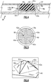
Figure 4 illustrates a sectioned view through a representative portion of theairfoil 58, andFigure 5 illustrates a top-down view of a representative portion of theairfoil 58. Thecover panel 62 includestabs 62a that project into thenode cavity 80. Aplug 82 is disposed in thenode cavity 80. Theplug 82 pinches thetabs 62a against therib walls 78a of thenode cavity 80, thereby locking thecover panel 62 on thebody 60. In this regard, the relatively continuous and smooth profile of thenode cavity 80 facilitates good contact and pressure distribution between theplug 82 and thetabs 62a. - To further facilitate mechanical locking, the
rib wall 78a that forms therib node 78 may include an undercut 78b. Theplug 82 may pinch thetabs 62a into the undercut 78b and thereby partially wrap thetabs 62a around therib wall 78a to prevent thetabs 62a from easily lifting out of thenode cavity 80. - As an example, as shown in an isolated view in
Figure 6 , thetabs 62a may be flaps that are cut from thecover panel 62. For instance, prior to fully curing thecover panel 62 during fabrication, thecover panel 62 may be cut in a cross pattern to form the flaps. The flaps may then be bent out-of-plane from the remainder of thecover panel 62 so that the flaps can extend into thenode cavity 80. As will be appreciated, other patterns could be used to produce other flap shapes. - The flaps may additionally be trimmed, to reduce the number of flaps and/or reduce size and weight. However, the flaps should at least be of a size that provides ample area for contact with the
plug 82. For instance, in the example shown inFigure 4 , thetabs 62a extend down the sides of therib walls 78a and partially across the bottom of therib cavity 80. Alternatively, thetabs 62a may be trimmed so as to extend only down to the bottom, or just short of the bottom, of therib cavity 80. Should thetabs 62a be too small, for example as to extend only less than 50% the distance down therib walls 78a to the bottom, the area for contact with theplug 82 may be insufficient to effectively pinch and secure thetabs 62a. - The bending of the flaps may be conducted prior to positioning the
cover panel 62 on thebody 60 or after such positioning. Once positioned, with thetabs 62a in thenode cavity 80, theplug 82 is inserted into thenode cavity 80. As an example, theplug 82 is initially a liquid or formable semi-solid that is introduced, such as by injection or pressing, into thenode cavity 80. The liquid or formable semi-solid subsequently solidifies to form thefinal plug 82. Theplug 82 traps thetabs 62a against therib walls 78a, to thereby fasten thecover panel 62 to thebody 60. - As will be appreciated, the
plug 82 has an exposed (aerodynamic)surface 82a (Figure 4 ) on the exterior of theairfoil 58. The exposedsurface 82a is flush with thecover panel 62 so as to form a relatively smooth and continuous aerodynamic surface. If, after fabrication, theplug 82 is not flush, theplug 82 may be machined, sanded, or otherwise smoothed so that it is flush. - The material of the
plug 82 may be co-processed with thecover panel 62. For example, theplug 82 and thecover panel 62 may be formed from the same composition of material or at least a common base polymer such that curing steps can overlap or be conducted simultaneously. In this regard, theplug 82 and thecover panel 62 may, in one example, be formed of epoxy or other thermoset polymer. Most typically, the selected polymer will be of relatively high strength and rigidity, rather than an elastomeric. Use of the same composition of material or at least of a common base polymer may also enhance adhesion bonding between theplug 82 and thecover panel 62, thereby facilitating locking theplug 82 in place. Alternatively, theplug 82 may be formed of a different composition than thecover panel 62 or at least a different base polymer. For instance, theplug 82 may be formed of a thermoplastic base-polymer that can be melted and injected into thenode cavity 80. - The material of the
plug 82 may also contain reinforcement or fillers in order to modify the properties for enhanced pinching of thetabs 62a. As an example, the material of theplug 82 may contain chopped fibers, such as short glass fibers, to increase strength and rigidity to facilitate trapping thetabs 62a. - The
cover panel 62 may be fully or partially pre-fabricated prior to installation on thebody 60 or partially or fully formed in place on thebody 60. Prefabrication may include fully or partially curing thecover panel 62 and plug 82 prior to installation on thebody 60, or fully or partially forming thecover panel 62 and plug 82 if formed of thermoplastic. If thecover panel 62 is formed from thermoplastic, it can be heated and re-shaped locally to conform to thebody 62 andrib nodes 78. Local thermal forming is not possible if thecover panel 62 is formed from thermoset and is fully cured. If thecover panel 62 is cured/consolidated in situ on thebody 60 during assembly, rigid or semi-rigid members may be provided in therecess 74 to support thecover panel 62 prior to and during the curing. One example of such members include foam inserts. -
Figure 7 illustrates a representative portion of anotherexample airfoil 158 that also includes abody 160 and acover panel 162. In this disclosure, like reference numerals designate like elements where appropriate and reference numerals with the addition of one-hundred or multiples thereof designate modified elements that are understood to incorporate the same features and benefits of the corresponding elements. Thebody 160 andcover panel 162 may generally have the same shape as shown inFigure 1 . However, rather than therib nodes 78 and plug 82, theairfoil 158 employs push fasteners 184 (one shown). Thepush fasteners 184 may be used in the locations where therib nodes 78 are shown inFigure 1 . Thepush fasteners 184 extend through thecover panel 162 and lock thecover panel 162 on thebody 160. - In this regard, the
body 160 is configured withholes 186 that receive and lock thepush fasteners 184. For instance, theholes 186 may defined in ribs of thebody 160. As an example, theholes 186 me be used in the same or similar locations as thenodes 78 of the prior examples. In the example illustrated inFigure 7 , thepush fastener 184 is configured as a cantilever snap-fit with one or moreflexible barbs 184a that extend from ahead 184b. Upon insertion into thehole 186, thebarbs 184a initially compress inwards to fit through the narrow portion of thehole 186. The hole includes an undercut 186a, and upon reaching the undercut 186a during insertion thebarbs 184a decompress and release outwards. The release cause thebarbs 184a to engage the upper edge of the undercut, thereby preventing the snap-fit fastener 184 from retracting from thehole 186. Thehead 184b is engaged with thecover panel 162 and thereby fastens thecover panel 162 to thebody 160. - In this example, the
head 184b is embedded in thecover panel 162. For instance, thecover panel 162 is formed of multiple layers, and thehead 184b is buried among the layers. Thehead 184b, therefore, is not exposed on the exterior surface of thecover panel 162. In a further example, the multiple layers of thecover panel 162 include one or more fiber-reinforced layers, such aslayers 188a/188b, and asurface film layer 188c. For instance, thelayers 188a/188b may be formed of the fiber-reinforced polymer composite described above. In one example, the fiber structure of one or both of thelayers 188a/188b is selected to approximate an isotropic material, to facilitate mechanical and thermal compatibility with thebody 160. For instance, thelayers 188a/188b each include a 0/+60/-60 triaxial braid, which provides thecover panel 162 with in-plane quasi-isotropic properties. In a further example, the fibers in the triaxial braid are glass fibers, which provides a coefficient of thermal expansion that closely matches the coefficient of thermal expansion of atitanium body 60. - The
surface film layer 188c serves to enhance resistance to wear/erosion. For instance, thesurface film layer 188c may be formed of an elastomer, such as a fluoroelastomer. - As also shown in
Figure 7 , anadhesive layer 190 may optionally be used between thecover panel 162 and thebody 160. For instance, theadhesive layer 190 may be provided on a perimeter ledge of thebody 160, similar to theperimeter edge 74a shown inFigure 3 . Theadhesive layer 190 may be, but is not limited to, epoxy. Although thepush fasteners 184 secure thecover panel 162 on thebody 160, theadhesive layer 190 may be used to further facilitate securement and/or reduce play between thecover panel 162 and thebody 160. - In a further example shown in
Figure 8 , theribs 76 may include aflange 76a upon which thecover panel 162 sits. Theadhesive layer 190 may be situated on theflange 76a. Theadhesive layer 190 on theflange 76a may be used to increase the surface bonding area in addition to adhesive on the perimeter ledge. Theflange 76a thereby provides additional surface area for the purpose of bonding, yet minimizes mass of thebody 162 in comparison to a solid body or thicker ribs. -
Figure 9 illustrates a further example in which thecover panel 162 includesstitching 192 adjacent thehead 184b of thepush fastener 184. The stitching reinforces thecover panel 162 and facilitates reduction in delamination between thelayers 188a/188b, particularly during an impact. As an example, thestitching 192 may be formed of fibers of aramid, carbon, glass, or polyethylene, but is not limited thereto. -
Figure 10 illustrates another example of apush fastener 284. In this example, thepush fastener 284 includes radialflexible barbs 284a and thebody 160 includes astraight hole 286. Thebarbs 284a are carried on a shank that extends from thehead 284b. Thebarbs 284a is received into thestraight hole 286 to secure thecover panel 162 to thebody 160. Upon insertion of thebarbs 284a into thehole 286, thebarbs 284a are compressed and deflect or deform. Thebarbs 284a tend to decompress and thus press outwards on thehole 286 to hold thefastener 284, and thus thecover panel 162, in place. - In a further example, the
push fastener 184/284 may be installed "wet" with a paste adhesive to further bond and strengthen the attachment of thecover panel 162 to thebody 160. In this regard, thepush fasteners 184/284 may include one or more internal channels, depicted at 287 (Figures 7, 9 , and10 ) to permit injection of the adhesive paste through the head of thefasteners 184/284 and into thehole 186/286 to bond thefasteners 184/284 to the sides of thehole 186/286. -
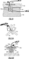
Figure 11A and 11B illustrate a modified example in which thenode 78 defines anode recess 78c. In this example, thecover panel 162 conforms to thenode recess 78c such that there is adimple 162b in thecover panel 162. Thehead 284b of thefastener 284 is situated in thedimple 162b. This "low profile" configuration permits thehead 284b to sit flush with, or below, the surface of thecover panel 162 immediately surrounding thedimple 162b, to enhance aerodynamics. - Although a combination of features is shown in the illustrated examples, not all of them need to be combined to realize the benefits of various embodiments of this disclosure. In other words, a system designed according to an embodiment of this disclosure will not necessarily include all of the features shown in any one of the Figures or all of the portions schematically shown in the Figures. Moreover, selected features of one example embodiment may be combined with selected features of other example embodiments.
- The preceding description is exemplary rather than limiting in nature. Variations and modifications to the disclosed examples may become apparent to those skilled in the art that do not necessarily depart from this disclosure. The scope of legal protection given to this disclosure can only be determined by studying the following claims.
Claims (15)
- An airfoil (58) comprising:a body (60) having rib nodes (78) that each define a node cavity (80) therein;a cover panel (62) carried on the body (60) over the rib nodes (78), the cover panel (62) including tabs (62a) that project into the node cavities (80); andplugs (82) disposed in the node cavities (80) and pinching the tabs (62a) against the node cavities (80), locking the cover panel (62) on the body (60).
- The airfoil as recited in claim 1, wherein each of the plugs (82) includes an exposed surface (82a) that is flush with the cover panel (62).
- The airfoil as recited in claim 1 or 2, wherein each of the rib nodes (78) includes an undercut (78b).
- The airfoil as recited in claim 1, 2 or 3, wherein the cover panel (62) includes a plurality of the tabs (62a) in each of the node cavities (80).
- The airfoil as recited in any preceding claim, wherein the tabs (62a) are flaps (62a) bent from the cover panel (62).
- The airfoil as recited in any preceding claim, wherein the cover panel (62) is a fiber-reinforced polymer composite, and the body (60) is metal.
- The airfoil as recited in any preceding claim, wherein each of the node cavities (80) is symmetric.
- The airfoil as recited in any preceding claim, wherein each of the node cavities (80) is round.
- The airfoil as recited in any preceding claim, wherein the plugs (82) are polymer-based, optionally fiber-reinforced polymer composite.
- An airfoil (158) comprising:a metal body (160);a cover panel (162) carried on the metal body (160); andpush fasteners (184; 284) extending through the cover panel (162) and locking the cover panel (162) on the metal body (160).
- The airfoil as recited in claim 10, wherein each of the push fasteners (184; 284) includes flexible barbs (184a; 284a).
- The airfoil as recited in claim 10 or 11, wherein each of the push fasteners (184) includes a head (184b) that is embedded in the cover panel (162).
- The airfoil as recited in claim 12, wherein the cover panel (162) includes stitching (192) adj acent the head (184b) of each of the push fasteners (184).
- The airfoil as recited in any of claims 10 to 13, wherein the metal body (160) includes holes (186) receiving the push fasteners (184; 284), and the holes (186) include undercuts (186a), and/or the metal body (160) includes straight holes (286) receiving the push fasteners (184; 284).
- A gas turbine engine (20) comprising:a fan (42);a compressor section (24);a combustor (26) in fluid communication with the compressor section (24); anda turbine section (28) in fluid communication with the combustor (26),wherein the fan (42) comprises airfoils (58), each as recited in any preceding claim.
Applications Claiming Priority (1)
| Application Number | Priority Date | Filing Date | Title |
|---|---|---|---|
| US16/251,537 US11203936B2 (en) | 2019-01-18 | 2019-01-18 | Airfoil with body and cover panel |
Publications (2)
| Publication Number | Publication Date |
|---|---|
| EP3683402A1 true EP3683402A1 (en) | 2020-07-22 |
| EP3683402B1 EP3683402B1 (en) | 2022-08-10 |
Family
ID=69185440
Family Applications (1)
| Application Number | Title | Priority Date | Filing Date |
|---|---|---|---|
| EP20152749.6A Active EP3683402B1 (en) | 2019-01-18 | 2020-01-20 | Airfoil with body and cover panel |
Country Status (2)
| Country | Link |
|---|---|
| US (3) | US11203936B2 (en) |
| EP (1) | EP3683402B1 (en) |
Families Citing this family (2)
| Publication number | Priority date | Publication date | Assignee | Title |
|---|---|---|---|---|
| US11913352B2 (en) * | 2021-12-08 | 2024-02-27 | General Electric Company | Cover plate connections for a hollow fan blade |
| US20240247593A1 (en) * | 2023-01-25 | 2024-07-25 | Raytheon Technologies Corporation | Two piece hollow-vane assembly joined via brazing |
Citations (4)
| Publication number | Priority date | Publication date | Assignee | Title |
|---|---|---|---|---|
| US5074752A (en) * | 1990-08-06 | 1991-12-24 | General Electric Company | Gas turbine outlet guide vane mounting assembly |
| US20050254942A1 (en) * | 2002-09-17 | 2005-11-17 | Siemens Westinghouse Power Corporation | Method of joining ceramic parts and articles so formed |
| EP2243929A2 (en) * | 2009-04-16 | 2010-10-27 | United Technologies Corporation | Hybrid structure fan blade |
| US20180135421A1 (en) * | 2016-11-17 | 2018-05-17 | United Technologies Corporation | Airfoil with panel fastened to core structure |
Family Cites Families (18)
| Publication number | Priority date | Publication date | Assignee | Title |
|---|---|---|---|---|
| US5741102A (en) * | 1996-07-19 | 1998-04-21 | Everett Industries Inc. | Removable quasi-ratchet fastener |
| US11603050B2 (en) * | 2006-11-29 | 2023-03-14 | Termax Company | Spring fastener |
| WO2003081056A1 (en) * | 2002-03-27 | 2003-10-02 | Tega Industries Limited | Fixing means for a screen panel and corresponding screen panel |
| US7247003B2 (en) * | 2004-12-02 | 2007-07-24 | Siemens Power Generation, Inc. | Stacked lamellate assembly |
| US7614836B2 (en) * | 2006-05-09 | 2009-11-10 | Gm Global Technology Operations, Inc. | Arrangements for attaching components to surfaces |
| US8357323B2 (en) * | 2008-07-16 | 2013-01-22 | Siemens Energy, Inc. | Ceramic matrix composite wall with post laminate stitching |
| US8585368B2 (en) * | 2009-04-16 | 2013-11-19 | United Technologies Corporation | Hybrid structure airfoil |
| WO2012125360A2 (en) * | 2011-03-17 | 2012-09-20 | A. Raymond Et Cie | Smart material actuated fasteners |
| CN103717378B (en) * | 2011-06-02 | 2016-04-27 | A·雷蒙德公司 | By the securing member that three dimensional printing manufactures |
| GB201115485D0 (en) | 2011-09-08 | 2011-10-26 | Rolls Royce Plc | An aerofoil assembly |
| US8944773B2 (en) * | 2011-11-01 | 2015-02-03 | United Technologies Corporation | Rotor blade with bonded cover |
| US9388791B2 (en) * | 2013-03-15 | 2016-07-12 | Frontier Wind, Llc | Mounting arrangement for load compensating device |
| US10323521B2 (en) * | 2013-03-15 | 2019-06-18 | United Technologies Corporation | Hybrid fan blade biscuit construction |
| US10280759B2 (en) * | 2016-05-25 | 2019-05-07 | United Technologies Corporation | Mechanically retained fan blade cover |
| US20180038386A1 (en) | 2016-08-08 | 2018-02-08 | United Technologies Corporation | Fan blade with composite cover |
| US10934850B2 (en) * | 2017-08-25 | 2021-03-02 | DOOSAN Heavy Industries Construction Co., LTD | Turbine blade having an additive manufacturing trailing edge |
| US10934870B2 (en) * | 2018-09-17 | 2021-03-02 | Rolls Royce Plc | Turbine vane assembly with reinforced end wall joints |
| US20200300093A1 (en) * | 2019-03-22 | 2020-09-24 | United Technologies Corporation | Method of manufacturing a multi-component article |
-
2019
- 2019-01-18 US US16/251,537 patent/US11203936B2/en active Active
-
2020
- 2020-01-20 EP EP20152749.6A patent/EP3683402B1/en active Active
-
2021
- 2021-11-18 US US17/529,392 patent/US11536142B2/en active Active
-
2022
- 2022-12-22 US US18/087,412 patent/US12031452B2/en active Active
Patent Citations (4)
| Publication number | Priority date | Publication date | Assignee | Title |
|---|---|---|---|---|
| US5074752A (en) * | 1990-08-06 | 1991-12-24 | General Electric Company | Gas turbine outlet guide vane mounting assembly |
| US20050254942A1 (en) * | 2002-09-17 | 2005-11-17 | Siemens Westinghouse Power Corporation | Method of joining ceramic parts and articles so formed |
| EP2243929A2 (en) * | 2009-04-16 | 2010-10-27 | United Technologies Corporation | Hybrid structure fan blade |
| US20180135421A1 (en) * | 2016-11-17 | 2018-05-17 | United Technologies Corporation | Airfoil with panel fastened to core structure |
Also Published As
| Publication number | Publication date |
|---|---|
| US20230304407A1 (en) | 2023-09-28 |
| EP3683402B1 (en) | 2022-08-10 |
| US20200232329A1 (en) | 2020-07-23 |
| US11536142B2 (en) | 2022-12-27 |
| US11203936B2 (en) | 2021-12-21 |
| US20220074310A1 (en) | 2022-03-10 |
| US12031452B2 (en) | 2024-07-09 |
Similar Documents
| Publication | Publication Date | Title |
|---|---|---|
| EP3564487B1 (en) | Composite airfoil for gas turbine engines and corresponding method of forming | |
| EP1046785B1 (en) | Composite fan platform | |
| EP3044415B1 (en) | Airfoil with an integrally stiffened composite cover | |
| EP3428399B1 (en) | Hollow fan blade with braided fabric tubes | |
| EP3643885B1 (en) | Platform for an airfoil of a gas turbine engine | |
| EP3282087B1 (en) | Fan, gas turbine engine with a fan, and method for creating a gas turbine engine fan | |
| US11092021B2 (en) | Fan platform with core and skin | |
| WO2014031203A2 (en) | Airfoil cover system | |
| US12031452B2 (en) | Airfoil with body and cover panel | |
| US12286905B2 (en) | Rotor assembly for gas turbine engines | |
| EP2956625B1 (en) | Stress mitigation feature for composite airfoil leading edge | |
| US20170101878A1 (en) | Low modulus insert for a component of a gas turbine engine | |
| EP3851644B1 (en) | Turbine fan fairing platform with protective surface | |
| US11391167B2 (en) | Hybrid airfoil for gas turbine engines |
Legal Events
| Date | Code | Title | Description |
|---|---|---|---|
| PUAI | Public reference made under article 153(3) epc to a published international application that has entered the european phase |
Free format text: ORIGINAL CODE: 0009012 |
|
| STAA | Information on the status of an ep patent application or granted ep patent |
Free format text: STATUS: THE APPLICATION HAS BEEN PUBLISHED |
|
| AK | Designated contracting states |
Kind code of ref document: A1 Designated state(s): AL AT BE BG CH CY CZ DE DK EE ES FI FR GB GR HR HU IE IS IT LI LT LU LV MC MK MT NL NO PL PT RO RS SE SI SK SM TR |
|
| AX | Request for extension of the european patent |
Extension state: BA ME |
|
| STAA | Information on the status of an ep patent application or granted ep patent |
Free format text: STATUS: REQUEST FOR EXAMINATION WAS MADE |
|
| 17P | Request for examination filed |
Effective date: 20210122 |
|
| RBV | Designated contracting states (corrected) |
Designated state(s): AL AT BE BG CH CY CZ DE DK EE ES FI FR GB GR HR HU IE IS IT LI LT LU LV MC MK MT NL NO PL PT RO RS SE SI SK SM TR |
|
| RAP1 | Party data changed (applicant data changed or rights of an application transferred) |
Owner name: RAYTHEON TECHNOLOGIES CORPORATION |
|
| GRAP | Despatch of communication of intention to grant a patent |
Free format text: ORIGINAL CODE: EPIDOSNIGR1 |
|
| STAA | Information on the status of an ep patent application or granted ep patent |
Free format text: STATUS: GRANT OF PATENT IS INTENDED |
|
| INTG | Intention to grant announced |
Effective date: 20220303 |
|
| RIN1 | Information on inventor provided before grant (corrected) |
Inventor name: FOSTER, LARRY Inventor name: MALMBORG, ERIC W. |
|
| GRAS | Grant fee paid |
Free format text: ORIGINAL CODE: EPIDOSNIGR3 |
|
| GRAA | (expected) grant |
Free format text: ORIGINAL CODE: 0009210 |
|
| STAA | Information on the status of an ep patent application or granted ep patent |
Free format text: STATUS: THE PATENT HAS BEEN GRANTED |
|
| AK | Designated contracting states |
Kind code of ref document: B1 Designated state(s): AL AT BE BG CH CY CZ DE DK EE ES FI FR GB GR HR HU IE IS IT LI LT LU LV MC MK MT NL NO PL PT RO RS SE SI SK SM TR |
|
| REG | Reference to a national code |
Ref country code: AT Ref legal event code: REF Ref document number: 1510685 Country of ref document: AT Kind code of ref document: T Effective date: 20220815 Ref country code: CH Ref legal event code: EP |
|
| REG | Reference to a national code |
Ref country code: IE Ref legal event code: FG4D |
|
| REG | Reference to a national code |
Ref country code: DE Ref legal event code: R096 Ref document number: 602020004379 Country of ref document: DE |
|
| REG | Reference to a national code |
Ref country code: NL Ref legal event code: MP Effective date: 20220810 |
|
| REG | Reference to a national code |
Ref country code: LT Ref legal event code: MG9D |
|
| PG25 | Lapsed in a contracting state [announced via postgrant information from national office to epo] |
Ref country code: SE Free format text: LAPSE BECAUSE OF FAILURE TO SUBMIT A TRANSLATION OF THE DESCRIPTION OR TO PAY THE FEE WITHIN THE PRESCRIBED TIME-LIMIT Effective date: 20220810 Ref country code: RS Free format text: LAPSE BECAUSE OF FAILURE TO SUBMIT A TRANSLATION OF THE DESCRIPTION OR TO PAY THE FEE WITHIN THE PRESCRIBED TIME-LIMIT Effective date: 20220810 Ref country code: PT Free format text: LAPSE BECAUSE OF FAILURE TO SUBMIT A TRANSLATION OF THE DESCRIPTION OR TO PAY THE FEE WITHIN THE PRESCRIBED TIME-LIMIT Effective date: 20221212 Ref country code: NO Free format text: LAPSE BECAUSE OF FAILURE TO SUBMIT A TRANSLATION OF THE DESCRIPTION OR TO PAY THE FEE WITHIN THE PRESCRIBED TIME-LIMIT Effective date: 20221110 Ref country code: NL Free format text: LAPSE BECAUSE OF FAILURE TO SUBMIT A TRANSLATION OF THE DESCRIPTION OR TO PAY THE FEE WITHIN THE PRESCRIBED TIME-LIMIT Effective date: 20220810 Ref country code: LV Free format text: LAPSE BECAUSE OF FAILURE TO SUBMIT A TRANSLATION OF THE DESCRIPTION OR TO PAY THE FEE WITHIN THE PRESCRIBED TIME-LIMIT Effective date: 20220810 Ref country code: LT Free format text: LAPSE BECAUSE OF FAILURE TO SUBMIT A TRANSLATION OF THE DESCRIPTION OR TO PAY THE FEE WITHIN THE PRESCRIBED TIME-LIMIT Effective date: 20220810 Ref country code: FI Free format text: LAPSE BECAUSE OF FAILURE TO SUBMIT A TRANSLATION OF THE DESCRIPTION OR TO PAY THE FEE WITHIN THE PRESCRIBED TIME-LIMIT Effective date: 20220810 |
|
| REG | Reference to a national code |
Ref country code: AT Ref legal event code: MK05 Ref document number: 1510685 Country of ref document: AT Kind code of ref document: T Effective date: 20220810 |
|
| PG25 | Lapsed in a contracting state [announced via postgrant information from national office to epo] |
Ref country code: PL Free format text: LAPSE BECAUSE OF FAILURE TO SUBMIT A TRANSLATION OF THE DESCRIPTION OR TO PAY THE FEE WITHIN THE PRESCRIBED TIME-LIMIT Effective date: 20220810 Ref country code: IS Free format text: LAPSE BECAUSE OF FAILURE TO SUBMIT A TRANSLATION OF THE DESCRIPTION OR TO PAY THE FEE WITHIN THE PRESCRIBED TIME-LIMIT Effective date: 20221210 Ref country code: HR Free format text: LAPSE BECAUSE OF FAILURE TO SUBMIT A TRANSLATION OF THE DESCRIPTION OR TO PAY THE FEE WITHIN THE PRESCRIBED TIME-LIMIT Effective date: 20220810 Ref country code: GR Free format text: LAPSE BECAUSE OF FAILURE TO SUBMIT A TRANSLATION OF THE DESCRIPTION OR TO PAY THE FEE WITHIN THE PRESCRIBED TIME-LIMIT Effective date: 20221111 |
|
| PG25 | Lapsed in a contracting state [announced via postgrant information from national office to epo] |
Ref country code: SM Free format text: LAPSE BECAUSE OF FAILURE TO SUBMIT A TRANSLATION OF THE DESCRIPTION OR TO PAY THE FEE WITHIN THE PRESCRIBED TIME-LIMIT Effective date: 20220810 Ref country code: RO Free format text: LAPSE BECAUSE OF FAILURE TO SUBMIT A TRANSLATION OF THE DESCRIPTION OR TO PAY THE FEE WITHIN THE PRESCRIBED TIME-LIMIT Effective date: 20220810 Ref country code: ES Free format text: LAPSE BECAUSE OF FAILURE TO SUBMIT A TRANSLATION OF THE DESCRIPTION OR TO PAY THE FEE WITHIN THE PRESCRIBED TIME-LIMIT Effective date: 20220810 Ref country code: DK Free format text: LAPSE BECAUSE OF FAILURE TO SUBMIT A TRANSLATION OF THE DESCRIPTION OR TO PAY THE FEE WITHIN THE PRESCRIBED TIME-LIMIT Effective date: 20220810 Ref country code: CZ Free format text: LAPSE BECAUSE OF FAILURE TO SUBMIT A TRANSLATION OF THE DESCRIPTION OR TO PAY THE FEE WITHIN THE PRESCRIBED TIME-LIMIT Effective date: 20220810 Ref country code: AT Free format text: LAPSE BECAUSE OF FAILURE TO SUBMIT A TRANSLATION OF THE DESCRIPTION OR TO PAY THE FEE WITHIN THE PRESCRIBED TIME-LIMIT Effective date: 20220810 |
|
| REG | Reference to a national code |
Ref country code: DE Ref legal event code: R097 Ref document number: 602020004379 Country of ref document: DE |
|
| PG25 | Lapsed in a contracting state [announced via postgrant information from national office to epo] |
Ref country code: SK Free format text: LAPSE BECAUSE OF FAILURE TO SUBMIT A TRANSLATION OF THE DESCRIPTION OR TO PAY THE FEE WITHIN THE PRESCRIBED TIME-LIMIT Effective date: 20220810 Ref country code: EE Free format text: LAPSE BECAUSE OF FAILURE TO SUBMIT A TRANSLATION OF THE DESCRIPTION OR TO PAY THE FEE WITHIN THE PRESCRIBED TIME-LIMIT Effective date: 20220810 |
|
| PLBE | No opposition filed within time limit |
Free format text: ORIGINAL CODE: 0009261 |
|
| STAA | Information on the status of an ep patent application or granted ep patent |
Free format text: STATUS: NO OPPOSITION FILED WITHIN TIME LIMIT |
|
| P01 | Opt-out of the competence of the unified patent court (upc) registered |
Effective date: 20230521 |
|
| PG25 | Lapsed in a contracting state [announced via postgrant information from national office to epo] |
Ref country code: AL Free format text: LAPSE BECAUSE OF FAILURE TO SUBMIT A TRANSLATION OF THE DESCRIPTION OR TO PAY THE FEE WITHIN THE PRESCRIBED TIME-LIMIT Effective date: 20220810 |
|
| 26N | No opposition filed |
Effective date: 20230511 |
|
| PG25 | Lapsed in a contracting state [announced via postgrant information from national office to epo] |
Ref country code: SI Free format text: LAPSE BECAUSE OF FAILURE TO SUBMIT A TRANSLATION OF THE DESCRIPTION OR TO PAY THE FEE WITHIN THE PRESCRIBED TIME-LIMIT Effective date: 20220810 |
|
| REG | Reference to a national code |
Ref country code: CH Ref legal event code: PL |
|
| PG25 | Lapsed in a contracting state [announced via postgrant information from national office to epo] |
Ref country code: LU Free format text: LAPSE BECAUSE OF NON-PAYMENT OF DUE FEES Effective date: 20230120 |
|
| REG | Reference to a national code |
Ref country code: BE Ref legal event code: MM Effective date: 20230131 |
|
| PG25 | Lapsed in a contracting state [announced via postgrant information from national office to epo] |
Ref country code: LI Free format text: LAPSE BECAUSE OF NON-PAYMENT OF DUE FEES Effective date: 20230131 Ref country code: CH Free format text: LAPSE BECAUSE OF NON-PAYMENT OF DUE FEES Effective date: 20230131 |
|
| PG25 | Lapsed in a contracting state [announced via postgrant information from national office to epo] |
Ref country code: BE Free format text: LAPSE BECAUSE OF NON-PAYMENT OF DUE FEES Effective date: 20230131 |
|
| PG25 | Lapsed in a contracting state [announced via postgrant information from national office to epo] |
Ref country code: IE Free format text: LAPSE BECAUSE OF NON-PAYMENT OF DUE FEES Effective date: 20230120 |
|
| PG25 | Lapsed in a contracting state [announced via postgrant information from national office to epo] |
Ref country code: IT Free format text: LAPSE BECAUSE OF FAILURE TO SUBMIT A TRANSLATION OF THE DESCRIPTION OR TO PAY THE FEE WITHIN THE PRESCRIBED TIME-LIMIT Effective date: 20220810 |
|
| PG25 | Lapsed in a contracting state [announced via postgrant information from national office to epo] |
Ref country code: MC Free format text: LAPSE BECAUSE OF FAILURE TO SUBMIT A TRANSLATION OF THE DESCRIPTION OR TO PAY THE FEE WITHIN THE PRESCRIBED TIME-LIMIT Effective date: 20220810 |
|
| PG25 | Lapsed in a contracting state [announced via postgrant information from national office to epo] |
Ref country code: MC Free format text: LAPSE BECAUSE OF FAILURE TO SUBMIT A TRANSLATION OF THE DESCRIPTION OR TO PAY THE FEE WITHIN THE PRESCRIBED TIME-LIMIT Effective date: 20220810 |
|
| PG25 | Lapsed in a contracting state [announced via postgrant information from national office to epo] |
Ref country code: BG Free format text: LAPSE BECAUSE OF FAILURE TO SUBMIT A TRANSLATION OF THE DESCRIPTION OR TO PAY THE FEE WITHIN THE PRESCRIBED TIME-LIMIT Effective date: 20220810 |
|
| PG25 | Lapsed in a contracting state [announced via postgrant information from national office to epo] |
Ref country code: BG Free format text: LAPSE BECAUSE OF FAILURE TO SUBMIT A TRANSLATION OF THE DESCRIPTION OR TO PAY THE FEE WITHIN THE PRESCRIBED TIME-LIMIT Effective date: 20220810 |
|
| PG25 | Lapsed in a contracting state [announced via postgrant information from national office to epo] |
Ref country code: CY Free format text: LAPSE BECAUSE OF FAILURE TO SUBMIT A TRANSLATION OF THE DESCRIPTION OR TO PAY THE FEE WITHIN THE PRESCRIBED TIME-LIMIT; INVALID AB INITIO Effective date: 20200120 |
|
| PG25 | Lapsed in a contracting state [announced via postgrant information from national office to epo] |
Ref country code: HU Free format text: LAPSE BECAUSE OF FAILURE TO SUBMIT A TRANSLATION OF THE DESCRIPTION OR TO PAY THE FEE WITHIN THE PRESCRIBED TIME-LIMIT; INVALID AB INITIO Effective date: 20200120 |
|
| REG | Reference to a national code |
Ref country code: DE Ref legal event code: R081 Ref document number: 602020004379 Country of ref document: DE Owner name: RTX CORPORATION (N.D.GES.D. STAATES DELAWARE),, US Free format text: FORMER OWNER: RAYTHEON TECHNOLOGIES CORPORATION, FARMINGTON, CT, US |
|
| PG25 | Lapsed in a contracting state [announced via postgrant information from national office to epo] |
Ref country code: TR Free format text: LAPSE BECAUSE OF FAILURE TO SUBMIT A TRANSLATION OF THE DESCRIPTION OR TO PAY THE FEE WITHIN THE PRESCRIBED TIME-LIMIT Effective date: 20220810 |
|
| PGFP | Annual fee paid to national office [announced via postgrant information from national office to epo] |
Ref country code: GB Payment date: 20251219 Year of fee payment: 7 |
|
| PGFP | Annual fee paid to national office [announced via postgrant information from national office to epo] |
Ref country code: FR Payment date: 20251217 Year of fee payment: 7 |
|
| PGFP | Annual fee paid to national office [announced via postgrant information from national office to epo] |
Ref country code: DE Payment date: 20251217 Year of fee payment: 7 |