EP3683399A1 - Rotary compressor and refrigeration cycle device - Google Patents
Rotary compressor and refrigeration cycle device Download PDFInfo
- Publication number
- EP3683399A1 EP3683399A1 EP19152114.5A EP19152114A EP3683399A1 EP 3683399 A1 EP3683399 A1 EP 3683399A1 EP 19152114 A EP19152114 A EP 19152114A EP 3683399 A1 EP3683399 A1 EP 3683399A1
- Authority
- EP
- European Patent Office
- Prior art keywords
- opening end
- end part
- sealing stopper
- rotary compressor
- connecting pipe
- Prior art date
- Legal status (The legal status is an assumption and is not a legal conclusion. Google has not performed a legal analysis and makes no representation as to the accuracy of the status listed.)
- Granted
Links
Images




Classifications
-
- F—MECHANICAL ENGINEERING; LIGHTING; HEATING; WEAPONS; BLASTING
- F04—POSITIVE - DISPLACEMENT MACHINES FOR LIQUIDS; PUMPS FOR LIQUIDS OR ELASTIC FLUIDS
- F04C—ROTARY-PISTON, OR OSCILLATING-PISTON, POSITIVE-DISPLACEMENT MACHINES FOR LIQUIDS; ROTARY-PISTON, OR OSCILLATING-PISTON, POSITIVE-DISPLACEMENT PUMPS
- F04C23/00—Combinations of two or more pumps, each being of rotary-piston or oscillating-piston type, specially adapted for elastic fluids; Pumping installations specially adapted for elastic fluids; Multi-stage pumps specially adapted for elastic fluids
- F04C23/008—Hermetic pumps
-
- F—MECHANICAL ENGINEERING; LIGHTING; HEATING; WEAPONS; BLASTING
- F01—MACHINES OR ENGINES IN GENERAL; ENGINE PLANTS IN GENERAL; STEAM ENGINES
- F01C—ROTARY-PISTON OR OSCILLATING-PISTON MACHINES OR ENGINES
- F01C21/00—Component parts, details or accessories not provided for in groups F01C1/00 - F01C20/00
- F01C21/10—Outer members for co-operation with rotary pistons; Casings
-
- F—MECHANICAL ENGINEERING; LIGHTING; HEATING; WEAPONS; BLASTING
- F04—POSITIVE - DISPLACEMENT MACHINES FOR LIQUIDS; PUMPS FOR LIQUIDS OR ELASTIC FLUIDS
- F04B—POSITIVE-DISPLACEMENT MACHINES FOR LIQUIDS; PUMPS
- F04B35/00—Piston pumps specially adapted for elastic fluids and characterised by the driving means to their working members, or by combination with, or adaptation to, specific driving engines or motors, not otherwise provided for
- F04B35/04—Piston pumps specially adapted for elastic fluids and characterised by the driving means to their working members, or by combination with, or adaptation to, specific driving engines or motors, not otherwise provided for the means being electric
-
- F—MECHANICAL ENGINEERING; LIGHTING; HEATING; WEAPONS; BLASTING
- F04—POSITIVE - DISPLACEMENT MACHINES FOR LIQUIDS; PUMPS FOR LIQUIDS OR ELASTIC FLUIDS
- F04B—POSITIVE-DISPLACEMENT MACHINES FOR LIQUIDS; PUMPS
- F04B39/00—Component parts, details, or accessories, of pumps or pumping systems specially adapted for elastic fluids, not otherwise provided for in, or of interest apart from, groups F04B25/00 - F04B37/00
- F04B39/02—Lubrication
- F04B39/0223—Lubrication characterised by the compressor type
- F04B39/023—Hermetic compressors
-
- F—MECHANICAL ENGINEERING; LIGHTING; HEATING; WEAPONS; BLASTING
- F04—POSITIVE - DISPLACEMENT MACHINES FOR LIQUIDS; PUMPS FOR LIQUIDS OR ELASTIC FLUIDS
- F04C—ROTARY-PISTON, OR OSCILLATING-PISTON, POSITIVE-DISPLACEMENT MACHINES FOR LIQUIDS; ROTARY-PISTON, OR OSCILLATING-PISTON, POSITIVE-DISPLACEMENT PUMPS
- F04C18/00—Rotary-piston pumps specially adapted for elastic fluids
- F04C18/30—Rotary-piston pumps specially adapted for elastic fluids having the characteristics covered by two or more of groups F04C18/02, F04C18/08, F04C18/22, F04C18/24, F04C18/48, or having the characteristics covered by one of these groups together with some other type of movement between co-operating members
- F04C18/34—Rotary-piston pumps specially adapted for elastic fluids having the characteristics covered by two or more of groups F04C18/02, F04C18/08, F04C18/22, F04C18/24, F04C18/48, or having the characteristics covered by one of these groups together with some other type of movement between co-operating members having the movement defined in group F04C18/08 or F04C18/22 and relative reciprocation between the co-operating members
- F04C18/356—Rotary-piston pumps specially adapted for elastic fluids having the characteristics covered by two or more of groups F04C18/02, F04C18/08, F04C18/22, F04C18/24, F04C18/48, or having the characteristics covered by one of these groups together with some other type of movement between co-operating members having the movement defined in group F04C18/08 or F04C18/22 and relative reciprocation between the co-operating members with vanes reciprocating with respect to the outer member
-
- F—MECHANICAL ENGINEERING; LIGHTING; HEATING; WEAPONS; BLASTING
- F04—POSITIVE - DISPLACEMENT MACHINES FOR LIQUIDS; PUMPS FOR LIQUIDS OR ELASTIC FLUIDS
- F04C—ROTARY-PISTON, OR OSCILLATING-PISTON, POSITIVE-DISPLACEMENT MACHINES FOR LIQUIDS; ROTARY-PISTON, OR OSCILLATING-PISTON, POSITIVE-DISPLACEMENT PUMPS
- F04C2240/00—Components
- F04C2240/80—Other components
- F04C2240/806—Pipes for fluids; Fittings therefor
Definitions
- Embodiments described herein relate generally to a rotary compressor including an airtight container filled with refrigerating machine oil and refrigeration cycle device.
- JP 4325751 B2 discloses a refrigeration cycle device formed by connecting a plurality of rotary compressors in parallel to a refrigerant circuit in which a refrigerant is circulated.
- a refrigeration cycle device of this kind in order to prevent refrigerating machine oil filled into a plurality of rotary compressors from being unevenly distributed between the rotary compressors, an operation of taking out surplus refrigerating machine oil in a rotary compressor from the rotary compressor and supplying the taken-out refrigerating machine oil to a rotary compressor lacking in refrigerating machine oil is carried out.
- An oil equalizing pipe configured to take out surplus refrigerating machine oil from the rotary compressor is connected to an airtight container of the rotary compressor.
- An opening end part of the oil equalizing pipe positioned outside the airtight container is sealed up by means of a rubber stopper disclosed in JP 2001-132644 A at the time of, for example, shipment of the rotary compressor filled with refrigerating machine oil from the factory.
- the rubber stopper is pressed into the opening end part of the oil equalizing pipe and is removed from the oil equalizing pipe when cycle piping is joined to the opening end part of the oil equalizing pipe.
- An object of the present invention is to obtain a rotary compressor in which an opening end part of a connecting pipe connected to the airtight container can firmly be sealed up by means of a sealing stopper, furthermore, the workability at the time when another piece of piping is inserted into the opening end part of the connecting pipe from which the sealing stopper is removed and the inserted piping is brazed to the opening end part is excellent and, the joint strength and sealability between the connecting pipe and the piping can sufficiently be secured.
- a rotary compressor in general, includes an airtight container accommodating therein a compression mechanism section configured to compress a working fluid, and filled with refrigerating machine oil configured to lubricate the compression mechanism section, a connecting pipe connected to the airtight container and including an opening end part opened to the outside of the airtight container, and a sealing stopper detachably fitted on the opening end part of the connecting pipe and tightly sealing up the opening end part.
- the sealing stopper includes a cylindrical peripheral wall part to be brazed to the connecting pipe in a state where the peripheral wall part surrounds an outer circumferential surface of the opening end part of the connecting pipe, and an end wall part provided in such a manner as to be continuous with the peripheral wall part and opposed to an apical surface of the opening end part.
- FIG. 1 is a refrigeration cycle circuit diagram of an air conditioner 1 which is, for example, an example of a refrigeration cycle device.
- the air conditioner 1 of this embodiment is constituted of one outdoor unit 2 and one indoor unit 3.
- the outdoor unit 2 is provided with two rotary compressors 4a and 4b configured to compress a refrigerant serving as a working fluid.
- the rotary compressors 4a and 4b respectively includes refrigerant discharge pipes 5a and 5b, and the refrigerant discharge pipes 5a and 5b are connected in parallel to one piece of high-pressure piping 6.
- an oil separator 7 To the high-pressure piping 6, an oil separator 7, a first port 8a and a second port 8b of a four-way valve 8, an outdoor heat exchanger 9, a liquid tank 10, and a liquid pipe 11 are connected.
- the rotary compressors 4a and 4b respectively include refrigerant suction pipes 14a and 14b.
- the refrigerant suction pipes 14a and 14b are respectively connected to suction cups 15a and 15b.
- Connecting ports 16a and 16b respectively belonging to the suction cups 15a and 15b are connected to one piece of low-pressure piping 18 respectively through refrigerant piping 17a and refrigerant piping 17b.
- an accumulator 19 To the low-pressure piping 18, an accumulator 19, a third port 8c and a fourth port 8d of the four-way valve 8, and a gas pipe 20 are connected.
- the liquid pipe 11 and the gas pipe 20 are routed from the outdoor unit 2 to the indoor unit 3.
- the liquid pipe 11 is connected to an indoor heat exchanger 23 through an expanding device 22 belonging to the indoor unit 3.
- the gas pipe 20 is also connected to the indoor heat exchanger 23 of the indoor unit 3. Accordingly, the high-pressure the piping 6, the liquid pipe 11, the refrigerant piping 17a and the refrigerant piping 17b, the low-pressure piping 18, and the gas pipe 20 cooperate with each other to constitute a circulation circuit 24 configured to circulate the refrigerant between the outdoor unit 2 and the indoor unit 3.
- the outdoor unit 2 is provided with an oil equalizing circuit 25 configured to prevent the refrigerating machine oil with which the rotary compressors 4a and 4b are filled from being unevenly distributed between the rotary compressors 4a and 4b.
- oil equalizing pipes 26a and 26b are respectively connected to the rotary compressors 4a and 4b.
- the oil equalizing pipes 26a and 26b are connected to an upper end of a common oil tank 28 respectively through cycle piping 27a and cycle piping 27b.
- An oil equalizing guide pipe 29 is connected to the side face of the oil tank 28.
- the oil equalizing guide pipe 29 is bifurcated halfway, and the bifurcated ends of the oil equalizing guide pipe 29 are respectively connected to the refrigerant piping 17a and refrigerant piping 17b.
- the oil tank 28 is connected to the high-pressure piping 6 through a bypass pipe 30. Furthermore, a first oil return pipe 31a and second oil return pipe 31b are connected in parallel between the oil separator 7 and the oil equalizing guide pipe 29.
- the first oil return pipe 31a is provided with a normally closed on-off valve 32.
- the air conditioner 1 having such a refrigeration cycle circuit, when the operation of the air conditioner 1 is started in the cooling mode, the high-temperature/high-pressure gas-phase refrigerant components compressed by the rotary compressors 4a and 4b are respectively guided from the refrigerant discharge pipes 5a and 5b to the oil separator 7 through the high-pressure piping 6.
- the gas-phase refrigerant from which the refrigerating machine oil is separated by the oil separator 7 is guided to the outdoor heat exchanger 9 functioning as a heat radiator (condenser) by way of the four-way valve 8, and is condensed by the heat exchange between the refrigerant and outdoor air.
- the high-pressure liquid-phase refrigerant condensed by the outdoor heat exchanger 9 is guided to the indoor unit 3 through the liquid tank 10 and the liquid pipe 11.
- the high-pressure gas-phase refrigerant is decompressed by the expanding device 22 and is changed into a low-pressure gas-liquid two-phase refrigerant.
- the gas-liquid two-phase refrigerant is guided to the indoor heat exchanger 23 functioning as a heat absorber (evaporator), and carries out heat exchange between itself and the indoor air during the process of passing through the indoor heat exchanger 23.
- the low-temperature/low-pressure gas-phase refrigerant passing through the indoor heat exchanger 23 is guided to the accumulator 19 through the gas pipe 20 and the four-way valve 8.
- the gas-phase refrigerant from which the liquid-phase refrigerant has been separated by the accumulator 19 is sucked into the rotary compressors 4a and 4b through the low-pressure piping 18, the refrigerant piping 17a and the refrigerant piping 17b, the suction cups 15a and 15b, and the refrigerant suction pipes 14a and 14b.
- the air conditioner 1 When the air conditioner 1 carries out an operation in the heating mode, the high-temperature/high-pressure gas-phase refrigerant compressed in the rotary compressors 4a and 4b flows in the direction opposite to the direction at the time of the operation in the cooling mode through the four-way valve 8, and the indoor heat exchanger 23 functions as a condenser.
- the indoor air passing through the indoor heat exchanger 23 is heated by heat exchange between the indoor air and gas-phase refrigerant.
- the high-pressure gas-phase refrigerant distributed from the high-pressure piping 6 to the bypass pipe 30 flows into the oil tank 28, and hence the refrigerating machine oil guided to the oil tank 28 is evenly distributed from the oil equalizing guide pipe 29 to the refrigerant piping 17a and the refrigerant piping 17b by the pressure of the gas-phase refrigerant applied to the oil tank 28.
- the refrigerating machine oil components distributed to the refrigerant piping 17a and the refrigerant piping 17b are sucked into the rotary compressors 4a and 4b from the suction cups 15a and 15b together with the gas-phase refrigerant circulating through the circulation circuit 24.
- the refrigerating machine oil and gas-phase refrigerant which have respectively flowed into the oil equalizing pipes 26a and 26b join each other inside the oil tank 28 and are evenly distributed from the oil equalizing guide pipe 29 to the refrigerant piping 17a and refrigerant piping 17b in the state where they are mixed with each other.
- the refrigerating machine oil moves from the one rotary compressor 4a toward the other rotary compressor 4b.
- the refrigerating machine oil In the gas-phase refrigerant discharged from the refrigerant discharge pipes 5a and 5b of the rotary compressors 4a and 4b, the refrigerating machine oil is contained.
- the refrigerating machine oil contained in the gas-phase refrigerant is guided from the high-pressure piping 6 to the oil separator 7, and is separated from the gas-phase refrigerant inside the oil separator 7.
- the oil level of the refrigerating machine oil collected in the oil separator 7 exceeds the connecting position of the second oil return pipe 31b connected to the oil separator 7, the amount of the refrigerating machine oil exceeding the connecting position is returned to the rotary compressors 4a and 4b through the second oil return pipe 31b and the oil equalizing guide pipe 29.
- the on-off valve 32 is opened. Thereby, the refrigerating machine oil accumulated in the oil tank 28 is returned to the rotary compressors 4a and 4b through the first oil return pipe 31a and the oil equalizing guide pipe 29.
- the rotary compressor 4a of this embodiment is a vertical two-cylinder rotary compressor and, FIG. 2 shows the form of the rotary compressor 4a immediately after shipment from the factory.
- the rotary compressor 4a is provided with an airtight container 35, an electric motor 36, and a compression mechanism section 37 as principal elements.
- the airtight container 35 includes a cylindrical peripheral wall 35a, and is made upright in the vertical direction.
- the refrigerant discharge pipe 5a is attached to the upper end part of the airtight container 35.
- the opening end positioned at the upper end of the refrigerant discharge pipe 5a is sealed up by means of a removable rubber stopper 38.
- the electric motor 36 is accommodated in the airtight container 35 at an intermediate part in the height direction of the airtight container 35.
- the stator 40 of the electric motor 36 is fixed to the inner surface of the peripheral wall 35a of the airtight container 35.
- the rotor 41 of the electric motor 36 is surrounded by the stator 40.
- the compression mechanism section 37 is accommodated in the airtight container 35 at the bottom part of the airtight container 35 in such a manner as to be positioned beneath the electric motor 36.
- the compression mechanism section 37 is provided with a first cylinder 42, a second cylinder 43, a partition plate 44, a first bearing 45, a second bearing 46, and a rotating shaft 47 as principal elements.
- the first cylinder 42 and the second cylinder 43 are arranged with a gap held between them in the axial direction of the airtight container 35.
- the partition plate 44 is interposed between the first cylinder 42 and the second cylinder 43.
- a top surface of the partition plate 44 is made in contact with an underside of the first cylinder 42 in such a manner as to cover the inner diameter part of the first cylinder 42 from below.
- An underside of the partition plate 44 is made in contact with a top surface of the second cylinder 43 in such a manner as to cover the inner diameter part of the second cylinder 43 from above.
- the first bearing 45 is arranged on the first cylinder 42 in such a manner as to cover the inner diameter part of the first cylinder 42 from above.
- the region surrounded by the inner diameter part of the first cylinder 42, the partition plate 44, and the first bearing 45 constitutes a first cylinder chamber 48.
- the second bearing 46 is arranged under the second cylinder 43 in such a manner as to cover the inner diameter part of the second cylinder 43 from below.
- the region surrounded by the inner diameter part of the second cylinder 43, the partition plate 44, and the second bearing 46 constitutes a second cylinder chamber 49.
- a first muffler cover 50 is attached to the first bearing 45.
- the first muffler cover 50 defines a first sound-muffling chamber 51 between itself and the first bearing 45.
- the first sound-muffling chamber 51 is opened to the inside of the airtight container 35 through an exhaust hole (not shown) included in the first muffler cover 50.
- a second muffler cover 52 is attached to the second bearing 46.
- the second muffler cover 52 defines a second sound-muffling chamber 53 between itself and the second bearing 46.
- the second sound-muffling chamber 53 is made to communicate with the first sound-muffling chamber 51 through a discharge pathway not shown.
- a fist discharge port 54 is formed in the first bearing 45.
- the first discharge port 54 is opened to the first cylinder chamber 48 and the first sound-muffling chamber 51 and is opened/closed by a reed valve 55.
- a second discharge port 56 is formed in the second bearing 46.
- the second discharge port 56 is opened to the second cylinder chamber 49 and the second sound-muffling chamber 53 and is opened/closed by a reed valve 57.
- a ring-shaped supporting member 60 is arranged around the first bearing 45.
- the supporting member 60 is fixed to the inner surface of the peripheral wall 35a of the airtight container 35 by means of welding or the like, and an outer circumferential part of the first cylinder 42 is fixed to the underside of the supporting member 60 by means of a first fastening bolt 61.
- the first cylinder 42, the second cylinder 43, the partition plate 44, the first bearing 45, the second bearing 46, the first muffler cover 50, and the second muffler cover 52 are integrally joined together by means of a second fastening bolt 62.
- the rotating shaft 47 has a central axis line O1 coaxially positioned with respect to the airtight container 35.
- the rotating shaft 47 is rotatably supported on the compression mechanism section 37 through the first bearing 45a and the second bearing 46, and is coupled to the rotor 41 of the electric motor 36.
- the rotating shaft 47 is provided with a pair of crank sections 64a and 64b respectively positioned in the first cylinder chamber 48 and the second cylinder chamber 49.
- Ring-shaped rollers 65a and 65b are respectively fitted on the outer circumferential surfaces of the crank sections 64a and 64b.
- the rollers 65a and 65b are eccentrically rotated inside the first cylinder chamber 48 and the second cylinder chamber 49. Thereby, the volumetric capacities of the compression region and inlet region of each of the first cylinder chamber 48 and the second cylinder chamber 49 are continuously changed.
- the first cylinder 42 includes an inlet port 66 opened to the inlet region of the first cylinder chamber 48.
- the inlet port 66 also communicates with the inlet region of the second cylinder chamber 49 through a refrigerant distribution pathway 67 provided in the partition plate 44.
- the suction cup 15a is attached to the side of the airtight container 35.
- the refrigerant suction pipe 14a protruded from the lower end part of the suction cup 15a penetrates the peripheral wall 35a of the airtight container 35, and is connected to the inlet port 66 of the first cylinder 42.
- Part of the refrigerant guided from the suction cup 15a to the inlet port 66 is sucked into the first cylinder chamber 48.
- the remaining refrigerant is sucked into the second cylinder chamber 49 from the inlet port 66 through the refrigerant distribution pathway 67.
- the connecting port 16a is attached to the upper end of the suction cup 15a.
- the opening end positioned at the upper end of the connecting port 16a is sealed up by means of a removable rubber stopper 68.
- the rollers 65a and 65b are respectively eccentrically rotated inside the first and second cylinder chambers 48 and 49, and gas-phase refrigerant inside the suction cup 15a is sucked into the inlet regions of the first and second cylinder chambers 48 and 49 through the inlet pipe 14a, the inlet port 66, and the refrigerant distribution pathway 67.
- the gas-phase refrigerant sucked into the first and second cylinder chambers 48 and 49 is compressed in the process in which the inlet region makes a transition to the compression region, and is discharged from the first sound-muffling chamber 51 to the inside of the airtight container 35 through the exhaust hole of the first muffler cover 50.
- the gas-phase refrigerant discharged to the inside of the airtight container 35 is passed through the electric motor 36 and is thereafter guided from the refrigerant discharge pipe 5a to the circulation circuit 24.
- the CO 2 -based refrigerant which is a kind of natural refrigerant is used as a refrigerant.
- the CO 2 -based refrigerant has pressure higher than the HFC-based refrigerant, and hence the pressure inside the airtight container 35 to which the refrigerant compressed in the first and second cylinder chambers 48 and 49 is discharged reaches 14 Mpa at the maximum in some cases.
- the compression mechanism section 37 is lubricated with the refrigerating machine oil filled into the airtight container 35. As shown in FIG. 2 , the oil level inside the airtight container 35 varies between the upper limit level H and the lower limit level L.
- the oil equalizing pipe 26a constituting the oil equalizing circuit 25 is an example of a connecting pipe and is constituted of, for example, a round pipe made of a copper alloy having a circular cross-sectional shape. As shown in FIG. 2 , the oil equalizing pipe 26a has a first opening end part 70 supported on the peripheral wall 35a of the airtight container 35 and a second opening end part 71 positioned on the opposite side of the first opening end part 70. The first opening end part 70 is opened to the inside of the airtight container 35 at a position between the upper limit level H and the lower limit level L of the refrigerating machine oil.
- the oil equalizing pipe 26a is protruded sideward from the airtight container 35 and is bent almost perpendicularly in such a manner that the second opening end part 71 is located at a position above the upper limit level H of the refrigerating machine oil.
- the second opening end part 71 of the oil equalizing pipe 26a is expanded wider in the radial direction than the first opening end part 70, and the inner diameter D1 of the second opening end part 71 is greater than the inner diameter D2 of the main part of the oil equalizing pipe 26a.
- the second opening end part 71 is formed into a cylindrical shape the inner diameter D1 and the outer diameter D3 of which are kept constant.
- the apical surface 71a of the oil equalizing pipe 26a defining the opening end of the second opening end part 71 is finished to a flat surface perpendicular to the axial direction of the second opening end part 71. Furthermore, the wall thickness T1 of the oil equalizing pipe 26a is kept approximately constant throughout the entire length of the oil equalizing pipe 26a from the first opening end part 70 to the second opening end part 71.
- the second opening end part 71 of the oil equalizing pipe 26a is sealed up by a removable sealing stopper 72.
- the sealing stopper 72 be formed of, for example, a copper-based metallic material identical to that for the oil equalizing pipe 26a such as a copper alloy or brass.
- the sealing stopper 72 has a peripheral wall part 73 and an end wall part 74.
- the peripheral wall part 73 is formed into a cylindrical shape continuously surrounding the outer circumferential surface of the second opening end part 71 in the circumferential direction.
- the end wall part 74 is continuous with one end of the peripheral wall part 73, and is opposed to the apical surface 71a which is the opening end of the second opening end part 71 from the direction in which the second opening end part 71 is opened. Accordingly, the peripheral wall part 73 and the end wall part 74 define a concave part 75 into which the second opening end part 71 is to be detachably fitted.
- the inner surface of the end wall part 74 serving as the bottom part of the concave part 75 is finished to a flat abutting surface 76. Accordingly, in the state where the second opening end part 71 of the oil equalizing pipe 26a is fitted into the concave part 75 of the sealing stopper 72, the apical surface 71a of the oil equalizing pipe 26a abuts against the abutting surface 76 of the end wall part 74 continuously in the circumferential direction.
- the apical surface 71a of the oil equalizing pipe 26a and the abutting surface 76 of the end wall part 74 maintain a state of surface contact continuously in the circumferential direction, and a gap is eliminated from the part between the apical surface 71a and the abutting surface 76.
- the wall thickness T2 of the end wall part 74 of the sealing stopper 72 is greater than the wall thickness T1 of the oil equalizing pipe 26a
- the wall thickness T3 of the peripheral wall part 73 is greater than the wall thickness T1 of the oil equalizing pipe 26a.
- the depth dimension d of the concave part 75 in the axial direction of the second opening end part 71 is greater than the inner diameter D1 of the second opening end part 71 of the oil equalizing pipe 26a.
- the sealing stopper 72 configured in this way is fitted on the second opening end part 71 of the oil equalizing pipe 26a from outside in the form of, for example, loose fitting, and is detachably joined to the oil equalizing pipe 26a at the peripheral wall part 73 thereof by brazing.
- a joint part 78 is formed by brazing on the outer circumferential surface of the second opening end part 71 at an end part of the peripheral wall part 73 on the opposite side of the end wall part 74.
- the joint part 78 can be obtained by solidification of the molten brazing material.
- the molten brazing material continuously spreads in the circumferential direction in such a manner as to be astride the end part of the peripheral wall part 73 and the outer circumferential surface of the second opening end part 71 and, at the same time, permeates through the clearance C between the inner circumferential surface of the peripheral wall part 73 and the outer circumferential surface of the opening end part 71 by the capillary phenomenon.
- the brazing material solidifies, whereby the sealing stopper 72 is firmly joined to the second opening end part 71 in the state where the sealing stopper 72 seals up the second opening end part 71.
- the joint part 78 formed astride the sealing stopper 72 and the oil equalizing pipes 26a, 26b is heated, and brazing material is melted, whereby the sealing stopper 72 is removed from the oil equalizing pipe 26a, 26b.
- the apical end part of the cycle piping 27a, 27b is inserted into the inner side of the second opening end part 71 of the oil equalizing pipe 26a, 26b, and is joined to the second opening end part 71 by brazing.
- the joint part 79 is formed between the apical surface 71a of the second opening end part 71 of the oil equalizing pipe 26a, 26b and the outer circumferential surface of the apical end part of the cycle piping 27a, 27b by brazing.
- the molten brazing material continuously spreads in the circumferential direction in such a manner as to be astride the apical surface 71a of the oil equalizing pipe 26a, 26b and the outer circumferential surface of the apical end part of the cycle piping 27a, 27b and, at the same time, permeates through the clearance between the inner circumferential surface of the second opening end part 71 and the outer circumferential surface of the apical end part of the cycle piping 27a, 27b by the capillary phenomenon.
- the brazing material solidifies, whereby the cycle piping 27a, 27b is firmly fixed to the second opening end part 71 of the oil equalizing pipe 26a, 26b.
- FIG. 4 discloses the state where only one rotary compressor 4a is incorporated into the circulation circuit 24.
- the oil equalizing circuit 25 becomes unnecessary. Accordingly, the second opening end part 71 of the oil equalizing pipe 26a is kept in the state where the second opening end part 71 is sealed up by the sealing stopper 72, and the sealing stopper 72 receives the pressure inside the airtight container 35 through the oil equalizing pipe 26a.
- the sealing stopper 72 configured to tightly seal up the second opening end part 71 of the oil equalizing pipe 26a is fitted on the second opening end part 71 in the state where the sealing stopper 72 covers the second opening end part 71 from outside.
- the sealing stopper 72 fitted on the second opening end part 71 is joined to the outer circumferential surface of the second opening end part 71 by brazing at the end part of the peripheral wall part 73 thereof on the opposite side of the end wall part 74.
- the sealing stopper 72 to firmly seal up the second opening end part 71 in such a manner as to overcome the pressure inside the airtight container 35 acting on the second opening end part 71 of the oil equalizing pipe 26a, and sufficiently secure the airtightness of the airtight container 35 even in a rotary compressor 4a handling a high-pressure refrigerant such as the CO 2 -based refrigerant.
- the molten existing brazing material is only kept in the state where the molten brazing material adheres to a position on the outer circumferential surface of the second opening end part 71 separate from the apical surface 71a of the second opening end part 71.
- the sealing stopper 72 is formed of a copper-based metallic material identical to that for the oil equalizing pipe 26a such as a copper ally or brass. For this reason, the thermal expansion coefficients of the sealing stopper 72 and oil equalizing pipe 26a become equal to each other, whereby it is possible to easily carry out the brazing work.
- the apical surface 71a of the oil equalizing pipe 26a and the abutting surface 76 of the sealing stopper 72 maintain a state of surface contact continuously in the circumferential direction, and a gap is eliminated from the part between the apical surface 71a and the abutting surface 76.
- the apical surface 71a of the oil equalizing pipe 26a is sealed up by the abutting surface 76 of the sealing stopper 72 and, even if by any chance, the molten brazing material reaches a position in the vicinity of the apical surface 71a of the oil equalizing pipe 26a through the clearance C between the inner circumferential surface of the peripheral wall part 73 of the sealing stopper 72 and the outer circumferential surface of the second opening end part 71 of the oil equalizing pipe 26a, the molten brazing material never adheres to the apical surface 71a of the oil equalizing pipe 26a.
- the end wall part 74 of the sealing stopper 72 sealing up the second opening end part 71 of the oil equalizing pipe 26a directly receives the pressure of the gas-phase refrigerant discharged to the inside of the airtight container 35.
- the wall thickness T2 of the end wall part 74 is greater than the wall thickness T1 of the oil equalizing pipe 26a, and hence it is possible to maintain the pressure resistance fatigue strength of the sealing stopper 72 at a level higher than or equal to that of the oil equalizing pipe 26a.
- the depth dimension d of the concave part 75 of the sealing stopper 72 is greater than the inner diameter D1 of the second opening end part 71 of the oil equalizing pipe 26a, and hence it is possible to secure a sufficient length of fit of the sealing stopper 72 with respect to the second opening end part 71.
- the pressure resistance fatigue strength of the sealing stopper 72 can be secured, even in the case of the rotary compressor 4a handling, particularly, the high-pressure refrigerant such as the CO 2 -based refrigerant, it is possible to firmly seal up the second opening end part 71 of the oil equalizing pipe 26a.
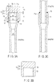
- FIG. 5A and FIG. 5B disclose a second embodiment.
- the second embodiment differs from the first embodiment in part of the configuration of the sealing stopper 72.
- the inner surface of the end wall part 74 of the sealing stopper 72 includes a recess part 100 opened at the center of the abutting surface 76.
- the recess part 100 has a shape cylindrically recessed in the direction away from the second opening end part 71.
- the inner diameter D4 of the recess part 100 is smaller than the inner diameter D1 of the second opening end part 71, and a step part 101 having a step-like shape is formed at the boundary between the recess part 100 and the abutting surface 76.
- the wall thickness T4 of the end wall part 74 at the position corresponding to the recess part 100 is greater than the wall thickness T1 of the oil equalizing pipe 26a so that the end wall part 74 can withstand the pressure inside the airtight container 35.
- the apical surface 71a of the oil equalizing pipe 26a and the abutting surface 76 of the sealing stopper 72 maintain a state of surface contact continuously in the circumferential direction.
- the molten brazing material reaches a position in the vicinity of the apical surface 71a of the oil equalizing pipe 26a through the clearance C between the outer circumferential surface of the second opening end part 71 and the inner circumferential surface of the peripheral wall part 73 of the sealing stopper 72, the molten brazing material can be prevented from adhering to the apical surface 71a of the oil equalizing pipe 26a.
- the recess part 100 serves the function of eliminating the superfluous thickness/weight from the end wall part 74, i.e., carrying out a kind of thickness/weight reduction, and the weight of the sealing stopper 72 can be reduced correspondingly.
- FIG. 6A and FIG. 6B disclose a third embodiment.
- the third embodiment differs from the first embodiment in part of the configuration of the sealing stopper 72.
- an inner surface 110 of the end wall part 74 of the sealing stopper 72 has a conical shape inclined in such a manner that the greater the distance from the beginning of the inner surface 110 in the direction toward the center of the inner surface 110, the farther the inner surface 110 becomes away from the apical surface 71a of the second opening end part 71, and thus the end wall part 74 and the second opening end part 71 define a space 111 having a tapering-off shape between them. Accordingly, the inner circumferential part of the inner surface 110 of the end wall part 74 is separate from the apical surface 71a of the second opening end part 71 without being in contact with the apical surface 71a.
- the minimum wall thickness T5 of the end wall part 74 at the position corresponding to the space 111 is greater than the wall thickness T1 of the oil equalizing pipe 26a so that the end wall part 74 can withstand the pressure inside the airtight container 35.
- the sealing stopper 72 when the sealing stopper 72 is brazed to the second opening end part 71 of the oil equalizing pipe 26a, even if the surplus molten brazing material reaches the apical surface 71a of the oil equalizing pipe 26a through the clearance C between the outer circumferential surface of the second opening end part 71 and the inner circumferential surface of the peripheral wall part 73 of the sealing stopper 72, the molten brazing material flows along the inner surface 110 of the end wall part 74 and then flows into the space 111 between the end wall part 74 and the second opening end part 71.
- the molten brazing material configured to join the sealing stopper 72 to the oil equalizing pipe 26a it becomes difficult for the molten brazing material configured to join the sealing stopper 72 to the oil equalizing pipe 26a to adhere to the apical surface 71a of the oil equalizing pipe 26a. Besides, when the joint part 78 is reheated, and the sealing stopper 72 is removed from the oil equalizing pipe 26a, the molten brazing material can be prevented from flowing into the inner side of the second opening end part 71 of the oil equalizing pipe 26a.
- FIG. 7A and FIG. 7B disclose a fourth embodiment.
- the fourth embodiment differs from the first embodiment in part of the configuration of the sealing stopper 72.
- a single groove 120 is formed in the inner circumferential surface of the peripheral wall part 73 of the sealing stopper 72.
- the groove 120 is continuous in the circumferential direction of the peripheral wall part 73 and is opened to the concave part 75 at an intermediate part of the concave part 75 of the sealing stopper 72 in the depth direction.
- the opening end of the groove 120 is opposed to the outer circumferential surface of the second opening end part 71.
- the groove 120 and the outer circumferential surface of the second opening end part 71 define a ring-shaped inflow chamber 121 between them.
- the inflow chamber 121 communicates with the clearance C between the inner circumferential surface of the peripheral wall part 73 of the sealing stopper 72 and the outer circumferential surface of the second opening end part 71 of the oil equalizing pipe 26a, and is separate from the apical surface 71a of the second opening end part 71.
- the sealing stopper 72 when the sealing stopper 72 is brazed to the second opening end part 71 of the oil equalizing pipe 26a, the surplus molten brazing material flowing into the clearance C between the outer circumferential surface of the second opening end part 71 and the inner circumferential surface of the peripheral wall part 73 of the sealing stopper 72 flows into the inflow chamber 121 from the clearance C.
- the number of the grooves 120 is not limited to one, and a plurality of grooves 120 may be arranged at intervals in the depth direction of the concave part 75 of the sealing stopper 72.
- FIG. 8 discloses a fifth embodiment.
- the fifth embodiment differs from the first embodiment in the configuration of the concave part 75 of the sealing stopper 72.
- the concave part 75 surrounded by the peripheral wall part 73 of the sealing stopper 72 is provided with a cylinder part 130 and a taper part 131.
- the cylinder part 130 is positioned on the opening end side of the concave part 75.
- the cylinder part 130 has an inner diameter D5 slightly greater than the outer diameter D3 of the second opening end part 71 so that a clearance C through which a molten brazing material permeates can be secured between the cylinder part 130 and the outer circumferential surface of the second opening end part 71 of the oil equalizing pipe 26a.
- the taper part 131 is positioned on the end wall part 74 side closer to the bottom part of the concave part 75.
- the taper part 131 is coaxially continuous with the end of the cylinder part 130, and the inner diameter D6 of the taper part 131 is formed in such a manner that the inner diameter D6 is continuously reduced as the distance from the cylinder part 130 becomes greater in the direction away from the cylinder part 130.
- the inner diameter D6 of the taper part 131 is set to a diameter equal to or less than the inner diameter D1 of the second opening end part 71. Accordingly, the inner circumferential surface 131a of the taper part 131 is inwardly inclined in the radial direction of the sealing stopper 72 as the distance from the cylinder part 130 becomes greater in the direction away from the cylinder part 130.
- the second opening end part 71 of the oil equalizing pipe 26a is to be tightly sealed up by means of the sealing stopper 72, the second opening end part 71 is inserted into the cylinder part 130 of the concave part 75.
- the inner diameter D6 of the taper part 131 continuous with the cylinder part 130 is continuously reduced as the distance from the cylinder part 130 becomes greater in the direction away from the cylinder part 130, and hence at the point in time when the second opening end part 71 is made to pass through the cylinder part 130 and enter the taper part 131, the outer circumferential edge of the apical surface 71a of the second opening end part 71 continuously abuts against the inner circumferential surface 131a of the taper part 131 in the circumferential direction.
- the apical surface 71a of the oil equalizing pipe 26a is sealed up by the inner circumferential surface 131a of the taper part 131 and, even if by any chance, the molten brazing material reaches a position in the vicinity of the apical surface 71a of the oil equalizing pipe 26a through the clearance C between the sealing stopper 72 and second opening end part 71, the molten brazing material can be avoided from adhering to the apical surface 71a of the oil equalizing pipe 26a.
- the sealing stopper 72 is provided with the taper part 131, and hence even when a variation in the outer diameter D3 of the second opening end part 71 occurs to a certain extent, the outer circumferential edge of the apical surface 71a of the oil equalizing pipe 26a continuously abuts against the inner circumferential surface 131a of the taper part 131 of the sealing stopper 72 in the circumferential direction. Accordingly, it is possible to prevent the molten brazing material from flowing toward the apical surface 71a of the oil equalizing pipe 26a.
- FIG. 9 discloses a sixth embodiment.
- the sixth embodiment differs from the fifth embodiment in the configuration of the concave part 75 of the sealing stopper 72.
- the concave part 75 is formed into a tapered shape configured in such a manner that the inner diameter D7 of the concave part 75 is continuously reduced as the distance from the opening end of concave part 75 becomes grater in the direction away from the opening end of the concave part 75 toward the end wall part 74 which is the bottom part of the concave part 75.
- the inner diameter D7 of the concave part 75 is less than the outer diameter D3 of the second opening end part 71.
- the inner circumferential surface 75a of the concave part 75 is inwardly inclined in the radial direction of the sealing stopper 72 as the distance from the opening end of the concave part 75 becomes greater in the direction away from the opening end of the concave part 75 toward the end thereof.
- the apical surface 71a of the oil equalizing pipe 26a is sealed up by the inner circumferential surface 75a of the concave part 75, and an advantage identical to the fifth embodiment can be obtained.
- FIG. 10 discloses a seventh embodiment.
- a part of the concave part 75 on the opening end side thereof is formed into a tapered shape, and a cylinder part 140 having a constant inner diameter D8 is provided on the end wall part 74 side so as to be continuous with the tapered part, the end wall part 74 being the bottom part of the concave part 75.
- Configurations of the sealing stopper 72 other than the above are identical to the sixth embodiment.
- the apical surface 71a of the oil equalizing pipe 26a is sealed up by the inner circumferential surface 75a of the concave part 75, and an advantage identical to the fifth embodiment can be obtained.
- the sealing stopper 72 is not limited to being brazed to the second opening end part 71 of the oil equalizing pipe 26a, and the sealing stopper 72 may also be brazed to an opening end part of a connecting pipe connected to the airtight container 35 such as the refrigerant discharge pipe 5a, 5b or the connecting port 16a, 16b of the suction cup 15a, 15b.
- the rotary compressor is not limited to the vertical type rotary compressor the airtight container of which is made upright, and the aforementioned embodiments can also be applied to a horizontal rotary compressor an airtight container of which is horizontally arranged.
Landscapes
- Engineering & Computer Science (AREA)
- Mechanical Engineering (AREA)
- General Engineering & Computer Science (AREA)
- Applications Or Details Of Rotary Compressors (AREA)
Abstract
Description
- Embodiments described herein relate generally to a rotary compressor including an airtight container filled with refrigerating machine oil and refrigeration cycle device.
- For example,
JP 4325751 B2 - An oil equalizing pipe configured to take out surplus refrigerating machine oil from the rotary compressor is connected to an airtight container of the rotary compressor. An opening end part of the oil equalizing pipe positioned outside the airtight container is sealed up by means of a rubber stopper disclosed in
JP 2001-132644 A - On the other hand, when a rotary compressor including an oil equalizing pipe is singly used, although the opening end part of the oil equalizing pipe is kept in the state where the opening end part is sealed up by means of the rubber stopper, the rubber stopper cannot withstand the pressure of the refrigerant. For this reason, it is necessary to separately prepare a dedicated rotary compressor including no oil equalizing pipe.
- As described above, heretofore, it has been necessary to prepare both a rotary compressor including an oil equalizing pipe and rotary compressor including no oil equalizing pipe according to the specifications of the refrigeration cycle device in which the rotary compressor is used, and thus it cannot be denied that the manufacture and management of the rotary compressor become complicated.
- An object of the present invention is to obtain a rotary compressor in which an opening end part of a connecting pipe connected to the airtight container can firmly be sealed up by means of a sealing stopper, furthermore, the workability at the time when another piece of piping is inserted into the opening end part of the connecting pipe from which the sealing stopper is removed and the inserted piping is brazed to the opening end part is excellent and, the joint strength and sealability between the connecting pipe and the piping can sufficiently be secured.
-
-
FIG. 1 is a circuit diagram schematically showing the configuration of a refrigeration cycle device according to a first embodiment. -
FIG. 2 is a cross-sectional view of a rotary compressor used in the refrigeration cycle device of the first embodiment. -
FIG. 3A is a cross-sectional view showing the part F3 inFIG. 2 in an enlarged form. -
FIG. 3B is a cross-sectional view of a sealing stopper used in the first embodiment. -
FIG. 3C is a cross-sectional view showing a state where cycle piping is inserted into a second opening end part of an oil equalizing pipe from which the sealing stopper is removed, and the cycle piping is brazed to the second opening end part in the first embodiment. -
FIG. 4 is a circuit diagram schematically showing the configuration of the refrigeration cycle device in which one rotary compressor including an oil equalizing pipe is incorporated in the circulation pathway in the first embodiment. -
FIG. 5A is a cross-sectional view showing a state where a sealing stopper is brazed to a second opening end part of an oil equalizing pipe in a second embodiment. -
FIG. 5B is a cross-sectional view of the sealing stopper used in the second embodiment. -
FIG. 6A is a cross-sectional view showing a state where a sealing stopper is brazed to a second opening end part of an oil equalizing pipe in a third embodiment. -
FIG. 6B is a cross-sectional view of the sealing stopper used in the third embodiment. -
FIG. 7A is a cross-sectional view showing a state where a sealing stopper is brazed to a second opening end part of an oil equalizing pipe in a fourth embodiment. -
FIG. 7B is a cross-sectional view of the sealing stopper used in the fourth embodiment. -
FIG. 8 is a cross-sectional view showing a state where a second opening end part of an oil equalizing pipe is inserted into a concave part of a sealing stopper in a fifth embodiment. -
FIG. 9 is a cross-sectional view showing a state where a second opening end part of an oil equalizing pipe is inserted into a concave part of a sealing stopper in a sixth embodiment. -
FIG. 10 is a cross-sectional view showing a state where a second opening end part of an oil equalizing pipe is inserted into a concave part of a sealing stopper in a seventh embodiment. - In general, according to one embodiment, a rotary compressor includes an airtight container accommodating therein a compression mechanism section configured to compress a working fluid, and filled with refrigerating machine oil configured to lubricate the compression mechanism section, a connecting pipe connected to the airtight container and including an opening end part opened to the outside of the airtight container, and a sealing stopper detachably fitted on the opening end part of the connecting pipe and tightly sealing up the opening end part.
- The sealing stopper includes a cylindrical peripheral wall part to be brazed to the connecting pipe in a state where the peripheral wall part surrounds an outer circumferential surface of the opening end part of the connecting pipe, and an end wall part provided in such a manner as to be continuous with the peripheral wall part and opposed to an apical surface of the opening end part.
- Hereinafter, a first embodiment will be described with reference to
FIG. 1 through FIG. 4 . -
FIG. 1 is a refrigeration cycle circuit diagram of anair conditioner 1 which is, for example, an example of a refrigeration cycle device. Theair conditioner 1 of this embodiment is constituted of oneoutdoor unit 2 and one indoor unit 3. Theoutdoor unit 2 is provided with tworotary compressors - The
rotary compressors refrigerant discharge pipes refrigerant discharge pipes pressure piping 6. To the high-pressure piping 6, an oil separator 7, afirst port 8a and asecond port 8b of a four-way valve 8, anoutdoor heat exchanger 9, aliquid tank 10, and aliquid pipe 11 are connected. - As shown in
FIG. 1 , therotary compressors refrigerant suction pipes refrigerant suction pipes suction cups ports suction cups pressure piping 18 respectively throughrefrigerant piping 17a andrefrigerant piping 17b. To the low-pressure piping 18, anaccumulator 19, athird port 8c and afourth port 8d of the four-way valve 8, and agas pipe 20 are connected. - The
liquid pipe 11 and thegas pipe 20 are routed from theoutdoor unit 2 to the indoor unit 3. Theliquid pipe 11 is connected to anindoor heat exchanger 23 through an expandingdevice 22 belonging to the indoor unit 3. Likewise, thegas pipe 20 is also connected to theindoor heat exchanger 23 of the indoor unit 3. Accordingly, the high-pressure thepiping 6, theliquid pipe 11, therefrigerant piping 17a and therefrigerant piping 17b, the low-pressure piping 18, and thegas pipe 20 cooperate with each other to constitute acirculation circuit 24 configured to circulate the refrigerant between theoutdoor unit 2 and the indoor unit 3. - As shown in
FIG. 1 , theoutdoor unit 2 is provided with an oil equalizingcircuit 25 configured to prevent the refrigerating machine oil with which therotary compressors rotary compressors circuit 25,oil equalizing pipes rotary compressors pipes common oil tank 28 respectively throughcycle piping 27a andcycle piping 27b. An oil equalizingguide pipe 29 is connected to the side face of theoil tank 28. The oil equalizingguide pipe 29 is bifurcated halfway, and the bifurcated ends of the oil equalizingguide pipe 29 are respectively connected to therefrigerant piping 17a andrefrigerant piping 17b. - The
oil tank 28 is connected to the high-pressure piping 6 through abypass pipe 30. Furthermore, a firstoil return pipe 31a and secondoil return pipe 31b are connected in parallel between the oil separator 7 and the oil equalizingguide pipe 29. The firstoil return pipe 31a is provided with a normally closed on-offvalve 32. - In the
air conditioner 1 having such a refrigeration cycle circuit, when the operation of theair conditioner 1 is started in the cooling mode, the high-temperature/high-pressure gas-phase refrigerant components compressed by therotary compressors refrigerant discharge pipes pressure piping 6. - The gas-phase refrigerant from which the refrigerating machine oil is separated by the oil separator 7 is guided to the
outdoor heat exchanger 9 functioning as a heat radiator (condenser) by way of the four-way valve 8, and is condensed by the heat exchange between the refrigerant and outdoor air. The high-pressure liquid-phase refrigerant condensed by theoutdoor heat exchanger 9 is guided to the indoor unit 3 through theliquid tank 10 and theliquid pipe 11. In the indoor unit 3, the high-pressure gas-phase refrigerant is decompressed by the expandingdevice 22 and is changed into a low-pressure gas-liquid two-phase refrigerant. The gas-liquid two-phase refrigerant is guided to theindoor heat exchanger 23 functioning as a heat absorber (evaporator), and carries out heat exchange between itself and the indoor air during the process of passing through theindoor heat exchanger 23. - The low-temperature/low-pressure gas-phase refrigerant passing through the
indoor heat exchanger 23 is guided to theaccumulator 19 through thegas pipe 20 and the four-way valve 8. The gas-phase refrigerant from which the liquid-phase refrigerant has been separated by theaccumulator 19 is sucked into therotary compressors pressure piping 18, therefrigerant piping 17a and therefrigerant piping 17b, thesuction cups refrigerant suction pipes - When the
air conditioner 1 carries out an operation in the heating mode, the high-temperature/high-pressure gas-phase refrigerant compressed in therotary compressors way valve 8, and theindoor heat exchanger 23 functions as a condenser. The indoor air passing through theindoor heat exchanger 23 is heated by heat exchange between the indoor air and gas-phase refrigerant. - Next, the operation of the
oil equalizing circuit 25 will be described below. - When the oil levels of the refrigerating machine oil with which the
rotary compressors oil equalizing pipes pipes rotary compressors oil equalizing pipes oil equalizing pipes oil tank 28 through thecycle piping 27a andcycle piping 27b. - The high-pressure gas-phase refrigerant distributed from the high-
pressure piping 6 to thebypass pipe 30 flows into theoil tank 28, and hence the refrigerating machine oil guided to theoil tank 28 is evenly distributed from the oil equalizingguide pipe 29 to therefrigerant piping 17a and therefrigerant piping 17b by the pressure of the gas-phase refrigerant applied to theoil tank 28. The refrigerating machine oil components distributed to therefrigerant piping 17a and therefrigerant piping 17b are sucked into therotary compressors suction cups circulation circuit 24. - On the other hand, during the operation of the
air conditioner 1, there is sometimes a case where unevenness in fill ration occurs in the tworotary compressors rotary compressor 4a is higher than the connecting position of theoil equalizing pipe 26a, and oil level of the refrigerating machine oil in the otherrotary compressor 4b is lower than the connecting position of theoil equalizing pipe 26b, the refrigerating machine oil flows into theoil equalizing pipe 26a corresponding to the onerotary compressor 4a, and high-pressure gas-phase refrigerant flows into theoil equalizing pipe 26b corresponding to the otherrotary compressor 4b. - The refrigerating machine oil and gas-phase refrigerant which have respectively flowed into the
oil equalizing pipes oil tank 28 and are evenly distributed from the oil equalizingguide pipe 29 to therefrigerant piping 17a andrefrigerant piping 17b in the state where they are mixed with each other. As a result, the refrigerating machine oil moves from the onerotary compressor 4a toward the otherrotary compressor 4b. - In the gas-phase refrigerant discharged from the
refrigerant discharge pipes rotary compressors pressure piping 6 to the oil separator 7, and is separated from the gas-phase refrigerant inside the oil separator 7. When the oil level of the refrigerating machine oil collected in the oil separator 7 exceeds the connecting position of the secondoil return pipe 31b connected to the oil separator 7, the amount of the refrigerating machine oil exceeding the connecting position is returned to therotary compressors oil return pipe 31b and the oil equalizingguide pipe 29. - Furthermore, when the oil levels of the refrigerating machine oil inside the two
rotary compressors oil equalizing pipes valve 32 is opened. Thereby, the refrigerating machine oil accumulated in theoil tank 28 is returned to therotary compressors oil return pipe 31a and the oil equalizingguide pipe 29. - Next, the specific configurations of the
rotary compressors rotary compressor 4a as a representative. - As shown in
FIG. 2 in cross section, therotary compressor 4a of this embodiment is a vertical two-cylinder rotary compressor and,FIG. 2 shows the form of therotary compressor 4a immediately after shipment from the factory. - The
rotary compressor 4a is provided with anairtight container 35, anelectric motor 36, and acompression mechanism section 37 as principal elements. Theairtight container 35 includes a cylindricalperipheral wall 35a, and is made upright in the vertical direction. Therefrigerant discharge pipe 5a is attached to the upper end part of theairtight container 35. At the point in time when therotary compressor 4a is shipped from the factory, the opening end positioned at the upper end of therefrigerant discharge pipe 5a is sealed up by means of aremovable rubber stopper 38. - The
electric motor 36 is accommodated in theairtight container 35 at an intermediate part in the height direction of theairtight container 35. Thestator 40 of theelectric motor 36 is fixed to the inner surface of theperipheral wall 35a of theairtight container 35. Therotor 41 of theelectric motor 36 is surrounded by thestator 40. - The
compression mechanism section 37 is accommodated in theairtight container 35 at the bottom part of theairtight container 35 in such a manner as to be positioned beneath theelectric motor 36. Thecompression mechanism section 37 is provided with afirst cylinder 42, asecond cylinder 43, apartition plate 44, afirst bearing 45, asecond bearing 46, and arotating shaft 47 as principal elements. - The
first cylinder 42 and thesecond cylinder 43 are arranged with a gap held between them in the axial direction of theairtight container 35. Thepartition plate 44 is interposed between thefirst cylinder 42 and thesecond cylinder 43. A top surface of thepartition plate 44 is made in contact with an underside of thefirst cylinder 42 in such a manner as to cover the inner diameter part of thefirst cylinder 42 from below. An underside of thepartition plate 44 is made in contact with a top surface of thesecond cylinder 43 in such a manner as to cover the inner diameter part of thesecond cylinder 43 from above. - The
first bearing 45 is arranged on thefirst cylinder 42 in such a manner as to cover the inner diameter part of thefirst cylinder 42 from above. The region surrounded by the inner diameter part of thefirst cylinder 42, thepartition plate 44, and thefirst bearing 45 constitutes afirst cylinder chamber 48. - The
second bearing 46 is arranged under thesecond cylinder 43 in such a manner as to cover the inner diameter part of thesecond cylinder 43 from below. The region surrounded by the inner diameter part of thesecond cylinder 43, thepartition plate 44, and thesecond bearing 46 constitutes asecond cylinder chamber 49. - A
first muffler cover 50 is attached to thefirst bearing 45. Thefirst muffler cover 50 defines a first sound-mufflingchamber 51 between itself and thefirst bearing 45. The first sound-mufflingchamber 51 is opened to the inside of theairtight container 35 through an exhaust hole (not shown) included in thefirst muffler cover 50. - A
second muffler cover 52 is attached to thesecond bearing 46. Thesecond muffler cover 52 defines a second sound-mufflingchamber 53 between itself and thesecond bearing 46. The second sound-mufflingchamber 53 is made to communicate with the first sound-mufflingchamber 51 through a discharge pathway not shown. - A
fist discharge port 54 is formed in thefirst bearing 45. Thefirst discharge port 54 is opened to thefirst cylinder chamber 48 and the first sound-mufflingchamber 51 and is opened/closed by a reed valve 55. - A
second discharge port 56 is formed in thesecond bearing 46. Thesecond discharge port 56 is opened to thesecond cylinder chamber 49 and the second sound-mufflingchamber 53 and is opened/closed by areed valve 57. - A ring-shaped supporting
member 60 is arranged around thefirst bearing 45. The supportingmember 60 is fixed to the inner surface of theperipheral wall 35a of theairtight container 35 by means of welding or the like, and an outer circumferential part of thefirst cylinder 42 is fixed to the underside of the supportingmember 60 by means of afirst fastening bolt 61. Furthermore, thefirst cylinder 42, thesecond cylinder 43, thepartition plate 44, thefirst bearing 45, thesecond bearing 46, thefirst muffler cover 50, and thesecond muffler cover 52 are integrally joined together by means of asecond fastening bolt 62. - As shown in
FIG. 2 , the rotatingshaft 47 has a central axis line O1 coaxially positioned with respect to theairtight container 35. The rotatingshaft 47 is rotatably supported on thecompression mechanism section 37 through the first bearing 45a and thesecond bearing 46, and is coupled to therotor 41 of theelectric motor 36. - The rotating
shaft 47 is provided with a pair of cranksections 64a and 64b respectively positioned in thefirst cylinder chamber 48 and thesecond cylinder chamber 49. Ring-shapedrollers crank sections 64a and 64b. Therollers first cylinder chamber 48 and thesecond cylinder chamber 49. Thereby, the volumetric capacities of the compression region and inlet region of each of thefirst cylinder chamber 48 and thesecond cylinder chamber 49 are continuously changed. - The
first cylinder 42 includes aninlet port 66 opened to the inlet region of thefirst cylinder chamber 48. Theinlet port 66 also communicates with the inlet region of thesecond cylinder chamber 49 through arefrigerant distribution pathway 67 provided in thepartition plate 44. - The
suction cup 15a is attached to the side of theairtight container 35. Therefrigerant suction pipe 14a protruded from the lower end part of thesuction cup 15a penetrates theperipheral wall 35a of theairtight container 35, and is connected to theinlet port 66 of thefirst cylinder 42. Part of the refrigerant guided from thesuction cup 15a to theinlet port 66 is sucked into thefirst cylinder chamber 48. The remaining refrigerant is sucked into thesecond cylinder chamber 49 from theinlet port 66 through therefrigerant distribution pathway 67. - Furthermore, the connecting
port 16a is attached to the upper end of thesuction cup 15a. At the point in time when therotary compressor 4a is shipped from the factory, the opening end positioned at the upper end of the connectingport 16a is sealed up by means of aremovable rubber stopper 68. - When the
rotating shaft 47 is rotated by theelectric motor 36, therollers second cylinder chambers suction cup 15a is sucked into the inlet regions of the first andsecond cylinder chambers inlet pipe 14a, theinlet port 66, and therefrigerant distribution pathway 67. - The gas-phase refrigerant sucked into the first and
second cylinder chambers chamber 51 to the inside of theairtight container 35 through the exhaust hole of thefirst muffler cover 50. The gas-phase refrigerant discharged to the inside of theairtight container 35 is passed through theelectric motor 36 and is thereafter guided from therefrigerant discharge pipe 5a to thecirculation circuit 24. - In this embodiment, the CO2-based refrigerant which is a kind of natural refrigerant is used as a refrigerant. The CO2-based refrigerant has pressure higher than the HFC-based refrigerant, and hence the pressure inside the
airtight container 35 to which the refrigerant compressed in the first andsecond cylinder chambers - According to this embodiment, the
compression mechanism section 37 is lubricated with the refrigerating machine oil filled into theairtight container 35. As shown inFIG. 2 , the oil level inside theairtight container 35 varies between the upper limit level H and the lower limit level L. - The
oil equalizing pipe 26a constituting theoil equalizing circuit 25 is an example of a connecting pipe and is constituted of, for example, a round pipe made of a copper alloy having a circular cross-sectional shape. As shown inFIG. 2 , theoil equalizing pipe 26a has a firstopening end part 70 supported on theperipheral wall 35a of theairtight container 35 and a secondopening end part 71 positioned on the opposite side of the first openingend part 70. The firstopening end part 70 is opened to the inside of theairtight container 35 at a position between the upper limit level H and the lower limit level L of the refrigerating machine oil. - The
oil equalizing pipe 26a is protruded sideward from theairtight container 35 and is bent almost perpendicularly in such a manner that the secondopening end part 71 is located at a position above the upper limit level H of the refrigerating machine oil. - As shown in
FIG. 3A , the secondopening end part 71 of theoil equalizing pipe 26a is expanded wider in the radial direction than the first openingend part 70, and the inner diameter D1 of the secondopening end part 71 is greater than the inner diameter D2 of the main part of theoil equalizing pipe 26a. The secondopening end part 71 is formed into a cylindrical shape the inner diameter D1 and the outer diameter D3 of which are kept constant. - The
apical surface 71a of theoil equalizing pipe 26a defining the opening end of the secondopening end part 71 is finished to a flat surface perpendicular to the axial direction of the secondopening end part 71. Furthermore, the wall thickness T1 of theoil equalizing pipe 26a is kept approximately constant throughout the entire length of theoil equalizing pipe 26a from the first openingend part 70 to the secondopening end part 71. - At the point in time when the
rotary compressor 4a is shipped from the factory, the secondopening end part 71 of theoil equalizing pipe 26a is sealed up by aremovable sealing stopper 72. It is desirable that the sealingstopper 72 be formed of, for example, a copper-based metallic material identical to that for theoil equalizing pipe 26a such as a copper alloy or brass. - As shown in
FIG. 3A and FIG. 3B , the sealingstopper 72 has aperipheral wall part 73 and anend wall part 74. Theperipheral wall part 73 is formed into a cylindrical shape continuously surrounding the outer circumferential surface of the secondopening end part 71 in the circumferential direction. Theend wall part 74 is continuous with one end of theperipheral wall part 73, and is opposed to theapical surface 71a which is the opening end of the secondopening end part 71 from the direction in which the secondopening end part 71 is opened. Accordingly, theperipheral wall part 73 and theend wall part 74 define aconcave part 75 into which the secondopening end part 71 is to be detachably fitted. - According to this embodiment, the inner surface of the
end wall part 74 serving as the bottom part of theconcave part 75 is finished to a flat abuttingsurface 76. Accordingly, in the state where the secondopening end part 71 of theoil equalizing pipe 26a is fitted into theconcave part 75 of the sealingstopper 72, theapical surface 71a of theoil equalizing pipe 26a abuts against the abuttingsurface 76 of theend wall part 74 continuously in the circumferential direction. - In other words, the
apical surface 71a of theoil equalizing pipe 26a and the abuttingsurface 76 of theend wall part 74 maintain a state of surface contact continuously in the circumferential direction, and a gap is eliminated from the part between theapical surface 71a and the abuttingsurface 76. - Furthermore, the wall thickness T2 of the
end wall part 74 of the sealingstopper 72 is greater than the wall thickness T1 of theoil equalizing pipe 26a, and the wall thickness T3 of theperipheral wall part 73 is greater than the wall thickness T1 of theoil equalizing pipe 26a. In addition, the depth dimension d of theconcave part 75 in the axial direction of the secondopening end part 71 is greater than the inner diameter D1 of the secondopening end part 71 of theoil equalizing pipe 26a. - The sealing
stopper 72 configured in this way is fitted on the secondopening end part 71 of theoil equalizing pipe 26a from outside in the form of, for example, loose fitting, and is detachably joined to theoil equalizing pipe 26a at theperipheral wall part 73 thereof by brazing. - More specifically, as shown in
FIG. 3A , ajoint part 78 is formed by brazing on the outer circumferential surface of the secondopening end part 71 at an end part of theperipheral wall part 73 on the opposite side of theend wall part 74. Thejoint part 78 can be obtained by solidification of the molten brazing material. At the time of brazing, the molten brazing material continuously spreads in the circumferential direction in such a manner as to be astride the end part of theperipheral wall part 73 and the outer circumferential surface of the secondopening end part 71 and, at the same time, permeates through the clearance C between the inner circumferential surface of theperipheral wall part 73 and the outer circumferential surface of the openingend part 71 by the capillary phenomenon. Thereafter, the brazing material solidifies, whereby the sealingstopper 72 is firmly joined to the secondopening end part 71 in the state where the sealingstopper 72 seals up the secondopening end part 71. - When the two
rotary compressors oil equalizing circuit 25, thejoint part 78 formed astride the sealingstopper 72 and theoil equalizing pipes stopper 72 is removed from theoil equalizing pipe FIG. 3C , the apical end part of thecycle piping opening end part 71 of theoil equalizing pipe opening end part 71 by brazing. - In this embodiment, the
joint part 79 is formed between theapical surface 71a of the secondopening end part 71 of theoil equalizing pipe cycle piping apical surface 71a of theoil equalizing pipe cycle piping opening end part 71 and the outer circumferential surface of the apical end part of thecycle piping cycle piping opening end part 71 of theoil equalizing pipe - On the other hand,
FIG. 4 discloses the state where only onerotary compressor 4a is incorporated into thecirculation circuit 24. When a CO2-based refrigerant is compressed by using the onerotary compressor 4a, theoil equalizing circuit 25 becomes unnecessary. Accordingly, the secondopening end part 71 of theoil equalizing pipe 26a is kept in the state where the secondopening end part 71 is sealed up by the sealingstopper 72, and the sealingstopper 72 receives the pressure inside theairtight container 35 through theoil equalizing pipe 26a. - According to the first embodiment, the sealing
stopper 72 configured to tightly seal up the secondopening end part 71 of theoil equalizing pipe 26a is fitted on the secondopening end part 71 in the state where the sealingstopper 72 covers the secondopening end part 71 from outside. The sealingstopper 72 fitted on the secondopening end part 71 is joined to the outer circumferential surface of the secondopening end part 71 by brazing at the end part of theperipheral wall part 73 thereof on the opposite side of theend wall part 74. - Accordingly, it is possible for the sealing
stopper 72 to firmly seal up the secondopening end part 71 in such a manner as to overcome the pressure inside theairtight container 35 acting on the secondopening end part 71 of theoil equalizing pipe 26a, and sufficiently secure the airtightness of theairtight container 35 even in arotary compressor 4a handling a high-pressure refrigerant such as the CO2-based refrigerant. - From the above description, it is possible to apply the
rotary compressors oil equalizing pipes rotary compressors circulation circuit 24 to be used and case where onerotary compressor - Moreover, according to the first embodiment, when the brazing material of the
joint part 78 is melted, and the sealingstopper 72 is removed from the secondopening end part 71, the molten existing brazing material is only kept in the state where the molten brazing material adheres to a position on the outer circumferential surface of the secondopening end part 71 separate from theapical surface 71a of the secondopening end part 71. - In other words, when the
cycle piping 27a is inserted into the inner side of the secondopening end part 71 from which the sealingstopper 72 has been removed, and is brazed to the secondopening end part 71, the existing brazing material which has formerly joined the sealingstopper 72 to the secondopening end part 71 never adheres to theapical surface 71a of the secondopening end part 71, theapical surface 71a being a surface with which another new brazing material is to be brought into contact. - As a result, when the
cycle piping 27a is brazed to the secondopening end part 71 of theoil equalizing pipe 26a, the troublesome and burdensome work of removing the existing brazing material is made unnecessary, and the workability at the time of brazing is improved. Accordingly, it is possible to sufficiently secure the joint strength and sealability of thejoint part 78 between theoil equalizing pipe 26a and thecycle piping 27a, this being appropriate for therotary compressor 4a handling a high-pressure refrigerant such as the CO2-based refrigerant. - According to this embodiment, the sealing
stopper 72 is formed of a copper-based metallic material identical to that for theoil equalizing pipe 26a such as a copper ally or brass. For this reason, the thermal expansion coefficients of the sealingstopper 72 andoil equalizing pipe 26a become equal to each other, whereby it is possible to easily carry out the brazing work. - In addition, even when the sealing
stopper 72 and theoil equalizing pipe 26a cause thermal expansion due to the heat of the brazing or the sealingstopper 72 and theoil equalizing pipe 26a cause thermal shrinkage after brazing, it is possible to avoid the clearance C between the inner circumferential surface of theperipheral wall part 73 of the sealingstopper 72 and the outer circumferential surface of the secondopening end part 71 of theoil equalizing pipe 26a from excessively becoming large. - Accordingly, when the sealing
stopper 72 is brazed to the secondopening end part 71 of theoil equalizing pipe 26a, it is possible to prevent the molten brazing material permeating through the clearance C between the outer circumferential surface of the secondopening end part 71 and the inner circumferential surface of theperipheral wall part 73 of the sealingstopper 72 from reaching theapical surface 71a of the secondopening end part 71. - In addition, in the state where the second
opening end part 71 of theoil equalizing pipe 26a is fitted into theconcave part 75 of the sealingstopper 72, theapical surface 71a of theoil equalizing pipe 26a and the abuttingsurface 76 of the sealingstopper 72 maintain a state of surface contact continuously in the circumferential direction, and a gap is eliminated from the part between theapical surface 71a and the abuttingsurface 76. - Accordingly, the
apical surface 71a of theoil equalizing pipe 26a is sealed up by the abuttingsurface 76 of the sealingstopper 72 and, even if by any chance, the molten brazing material reaches a position in the vicinity of theapical surface 71a of theoil equalizing pipe 26a through the clearance C between the inner circumferential surface of theperipheral wall part 73 of the sealingstopper 72 and the outer circumferential surface of the secondopening end part 71 of theoil equalizing pipe 26a, the molten brazing material never adheres to theapical surface 71a of theoil equalizing pipe 26a. Moreover, when thejoint part 78 is heated, and the sealingstopper 72 is removed from theoil equalizing pipe 26a, it is possible to prevent the molten brazing material from flowing into the inner side of the secondopening end part 71 of theoil equalizing pipe 26a. - As a result, when the sealing
stopper 72 is removed from the secondopening end part 71 of theoil equalizing pipe 26a, and thereafter thecycle piping 27a is inserted into the secondopening end part 71, it is possible to prevent the cycle piping 27a from being caught by the existing brazing material and prevent insertion of the cycle piping 27a from being disturbed. Accordingly, the workability at the time when thecycle piping 27a is brazed to the secondopening end part 71 of theoil equalizing pipe 26a is improved. - On the other hand, when one
rotary compressor 4a is used singly, theend wall part 74 of the sealingstopper 72 sealing up the secondopening end part 71 of theoil equalizing pipe 26a directly receives the pressure of the gas-phase refrigerant discharged to the inside of theairtight container 35. In this embodiment, the wall thickness T2 of theend wall part 74 is greater than the wall thickness T1 of theoil equalizing pipe 26a, and hence it is possible to maintain the pressure resistance fatigue strength of the sealingstopper 72 at a level higher than or equal to that of theoil equalizing pipe 26a. Furthermore, the depth dimension d of theconcave part 75 of the sealingstopper 72 is greater than the inner diameter D1 of the secondopening end part 71 of theoil equalizing pipe 26a, and hence it is possible to secure a sufficient length of fit of the sealingstopper 72 with respect to the secondopening end part 71. - Accordingly, in combination with the advantage that the pressure resistance fatigue strength of the sealing
stopper 72 can be secured, even in the case of therotary compressor 4a handling, particularly, the high-pressure refrigerant such as the CO2-based refrigerant, it is possible to firmly seal up the secondopening end part 71 of theoil equalizing pipe 26a. -
FIG. 5A and FIG. 5B disclose a second embodiment. The second embodiment differs from the first embodiment in part of the configuration of the sealingstopper 72. As shown inFIG. 5A and FIG. 5B , the inner surface of theend wall part 74 of the sealingstopper 72 includes arecess part 100 opened at the center of the abuttingsurface 76. Therecess part 100 has a shape cylindrically recessed in the direction away from the secondopening end part 71. The inner diameter D4 of therecess part 100 is smaller than the inner diameter D1 of the secondopening end part 71, and astep part 101 having a step-like shape is formed at the boundary between therecess part 100 and the abuttingsurface 76. - Furthermore, in this embodiment, the wall thickness T4 of the
end wall part 74 at the position corresponding to therecess part 100 is greater than the wall thickness T1 of theoil equalizing pipe 26a so that theend wall part 74 can withstand the pressure inside theairtight container 35. - According to the second embodiment, in the state where the second
opening end part 71 of theoil equalizing pipe 26a is fitted into theconcave part 75 of the sealingstopper 72, theapical surface 71a of theoil equalizing pipe 26a and the abuttingsurface 76 of the sealingstopper 72 maintain a state of surface contact continuously in the circumferential direction. Accordingly, even if by any chance, the molten brazing material reaches a position in the vicinity of theapical surface 71a of theoil equalizing pipe 26a through the clearance C between the outer circumferential surface of the secondopening end part 71 and the inner circumferential surface of theperipheral wall part 73 of the sealingstopper 72, the molten brazing material can be prevented from adhering to theapical surface 71a of theoil equalizing pipe 26a. - In addition, when the
joint part 78 is heated, and the sealingstopper 72 is removed from theoil equalizing pipe 26a, it is possible to prevent the molten brazing material from flowing into the inner side of the secondopening end part 71 of theoil equalizing pipe 26a. - Furthermore, the
recess part 100 serves the function of eliminating the superfluous thickness/weight from theend wall part 74, i.e., carrying out a kind of thickness/weight reduction, and the weight of the sealingstopper 72 can be reduced correspondingly. -
FIG. 6A and FIG. 6B disclose a third embodiment. The third embodiment differs from the first embodiment in part of the configuration of the sealingstopper 72. As shown inFIG. 6A and FIG. 6B , aninner surface 110 of theend wall part 74 of the sealingstopper 72 has a conical shape inclined in such a manner that the greater the distance from the beginning of theinner surface 110 in the direction toward the center of theinner surface 110, the farther theinner surface 110 becomes away from theapical surface 71a of the secondopening end part 71, and thus theend wall part 74 and the secondopening end part 71 define aspace 111 having a tapering-off shape between them. Accordingly, the inner circumferential part of theinner surface 110 of theend wall part 74 is separate from theapical surface 71a of the secondopening end part 71 without being in contact with theapical surface 71a. - Moreover, in this embodiment, the minimum wall thickness T5 of the
end wall part 74 at the position corresponding to thespace 111 is greater than the wall thickness T1 of theoil equalizing pipe 26a so that theend wall part 74 can withstand the pressure inside theairtight container 35. - According to the third embodiment, when the sealing
stopper 72 is brazed to the secondopening end part 71 of theoil equalizing pipe 26a, even if the surplus molten brazing material reaches theapical surface 71a of theoil equalizing pipe 26a through the clearance C between the outer circumferential surface of the secondopening end part 71 and the inner circumferential surface of theperipheral wall part 73 of the sealingstopper 72, the molten brazing material flows along theinner surface 110 of theend wall part 74 and then flows into thespace 111 between theend wall part 74 and the secondopening end part 71. - Accordingly, it becomes difficult for the molten brazing material configured to join the sealing
stopper 72 to theoil equalizing pipe 26a to adhere to theapical surface 71a of theoil equalizing pipe 26a. Besides, when thejoint part 78 is reheated, and the sealingstopper 72 is removed from theoil equalizing pipe 26a, the molten brazing material can be prevented from flowing into the inner side of the secondopening end part 71 of theoil equalizing pipe 26a. -
FIG. 7A and FIG. 7B disclose a fourth embodiment. The fourth embodiment differs from the first embodiment in part of the configuration of the sealingstopper 72. As shown inFIG. 7A and FIG. 7B , asingle groove 120 is formed in the inner circumferential surface of theperipheral wall part 73 of the sealingstopper 72. Thegroove 120 is continuous in the circumferential direction of theperipheral wall part 73 and is opened to theconcave part 75 at an intermediate part of theconcave part 75 of the sealingstopper 72 in the depth direction. - When the sealing
stopper 72 is brazed to the secondopening end part 71 of theoil equalizing pipe 26a, the opening end of thegroove 120 is opposed to the outer circumferential surface of the secondopening end part 71. - Accordingly, the
groove 120 and the outer circumferential surface of the secondopening end part 71 define a ring-shapedinflow chamber 121 between them. Theinflow chamber 121 communicates with the clearance C between the inner circumferential surface of theperipheral wall part 73 of the sealingstopper 72 and the outer circumferential surface of the secondopening end part 71 of theoil equalizing pipe 26a, and is separate from theapical surface 71a of the secondopening end part 71. - According to the fourth embodiment, when the sealing
stopper 72 is brazed to the secondopening end part 71 of theoil equalizing pipe 26a, the surplus molten brazing material flowing into the clearance C between the outer circumferential surface of the secondopening end part 71 and the inner circumferential surface of theperipheral wall part 73 of the sealingstopper 72 flows into theinflow chamber 121 from the clearance C. - Accordingly, it is possible to avoid the molten brazing material configured to join the sealing
stopper 72 to theoil equalizing pipe 26a from reaching theapical surface 71a of theoil equalizing pipe 26a. Therefore, as in the case of the first embodiment, when thecycle piping 27a is brazed to the secondopening end part 71 of theoil equalizing pipe 26a, the troublesome and burdensome work of removing the existing brazing material is made unnecessary and, at the same time, the work of brazing the cycle piping 27a to theoil equalizing pipe 26a can easily be carried out. - In the fourth embodiment, the number of the
grooves 120 is not limited to one, and a plurality ofgrooves 120 may be arranged at intervals in the depth direction of theconcave part 75 of the sealingstopper 72. -
FIG. 8 discloses a fifth embodiment. The fifth embodiment differs from the first embodiment in the configuration of theconcave part 75 of the sealingstopper 72. As shown inFIG. 8 , theconcave part 75 surrounded by theperipheral wall part 73 of the sealingstopper 72 is provided with acylinder part 130 and ataper part 131. - The
cylinder part 130 is positioned on the opening end side of theconcave part 75. Thecylinder part 130 has an inner diameter D5 slightly greater than the outer diameter D3 of the secondopening end part 71 so that a clearance C through which a molten brazing material permeates can be secured between thecylinder part 130 and the outer circumferential surface of the secondopening end part 71 of theoil equalizing pipe 26a. - The
taper part 131 is positioned on theend wall part 74 side closer to the bottom part of theconcave part 75. Thetaper part 131 is coaxially continuous with the end of thecylinder part 130, and the inner diameter D6 of thetaper part 131 is formed in such a manner that the inner diameter D6 is continuously reduced as the distance from thecylinder part 130 becomes greater in the direction away from thecylinder part 130. At the end of thetaper part 131, the inner diameter D6 of thetaper part 131 is set to a diameter equal to or less than the inner diameter D1 of the secondopening end part 71. Accordingly, the innercircumferential surface 131a of thetaper part 131 is inwardly inclined in the radial direction of the sealingstopper 72 as the distance from thecylinder part 130 becomes greater in the direction away from thecylinder part 130. - According to the fifth embodiment, when the second
opening end part 71 of theoil equalizing pipe 26a is to be tightly sealed up by means of the sealingstopper 72, the secondopening end part 71 is inserted into thecylinder part 130 of theconcave part 75. The inner diameter D6 of thetaper part 131 continuous with thecylinder part 130 is continuously reduced as the distance from thecylinder part 130 becomes greater in the direction away from thecylinder part 130, and hence at the point in time when the secondopening end part 71 is made to pass through thecylinder part 130 and enter thetaper part 131, the outer circumferential edge of theapical surface 71a of the secondopening end part 71 continuously abuts against the innercircumferential surface 131a of thetaper part 131 in the circumferential direction. - Thereby, the
apical surface 71a of theoil equalizing pipe 26a is sealed up by the innercircumferential surface 131a of thetaper part 131 and, even if by any chance, the molten brazing material reaches a position in the vicinity of theapical surface 71a of theoil equalizing pipe 26a through the clearance C between the sealingstopper 72 and secondopening end part 71, the molten brazing material can be avoided from adhering to theapical surface 71a of theoil equalizing pipe 26a. Besides, when the solidified brazing material is melted and the sealingstopper 72 is removed from theoil equalizing pipe 26a, it is possible to prevent the molten brazing material from flowing into the inner side of the secondopening end part 71 of theoil equalizing pipe 26a. - In addition, the sealing
stopper 72 is provided with thetaper part 131, and hence even when a variation in the outer diameter D3 of the secondopening end part 71 occurs to a certain extent, the outer circumferential edge of theapical surface 71a of theoil equalizing pipe 26a continuously abuts against the innercircumferential surface 131a of thetaper part 131 of the sealingstopper 72 in the circumferential direction. Accordingly, it is possible to prevent the molten brazing material from flowing toward theapical surface 71a of theoil equalizing pipe 26a. -
FIG. 9 discloses a sixth embodiment. The sixth embodiment differs from the fifth embodiment in the configuration of theconcave part 75 of the sealingstopper 72. As shown inFIG. 9 , theconcave part 75 is formed into a tapered shape configured in such a manner that the inner diameter D7 of theconcave part 75 is continuously reduced as the distance from the opening end ofconcave part 75 becomes grater in the direction away from the opening end of theconcave part 75 toward theend wall part 74 which is the bottom part of theconcave part 75. At theend wall part 74, the inner diameter D7 of theconcave part 75 is less than the outer diameter D3 of the secondopening end part 71. Accordingly, the innercircumferential surface 75a of theconcave part 75 is inwardly inclined in the radial direction of the sealingstopper 72 as the distance from the opening end of theconcave part 75 becomes greater in the direction away from the opening end of theconcave part 75 toward the end thereof. - In the sixth embodiment, when the second
opening end part 71 of theoil equalizing pipe 26a is inserted into theconcave part 75 of the sealingstopper 72, the outer circumferential edge of theapical surface 71a of the secondopening end part 71 continuously abuts against the innercircumferential surface 75a of theconcave part 75 in the circumferential direction. - Accordingly, the
apical surface 71a of theoil equalizing pipe 26a is sealed up by the innercircumferential surface 75a of theconcave part 75, and an advantage identical to the fifth embodiment can be obtained. -
FIG. 10 discloses a seventh embodiment. In the seventh embodiment, a part of theconcave part 75 on the opening end side thereof is formed into a tapered shape, and acylinder part 140 having a constant inner diameter D8 is provided on theend wall part 74 side so as to be continuous with the tapered part, theend wall part 74 being the bottom part of theconcave part 75. Configurations of the sealingstopper 72 other than the above are identical to the sixth embodiment. - In the seventh embodiment having the configuration described above too, when the second
opening end part 71 of theoil equalizing pipe 26a is inserted into theconcave part 75 of the sealingstopper 72, the outer circumferential edge of theapical surface 71a of the secondopening end part 71 continuously abuts against the innercircumferential surface 75a of theconcave part 75 in the circumferential direction. - Accordingly, the
apical surface 71a of theoil equalizing pipe 26a is sealed up by the innercircumferential surface 75a of theconcave part 75, and an advantage identical to the fifth embodiment can be obtained. - In the embodiments of the present invention, the sealing
stopper 72 is not limited to being brazed to the secondopening end part 71 of theoil equalizing pipe 26a, and the sealingstopper 72 may also be brazed to an opening end part of a connecting pipe connected to theairtight container 35 such as therefrigerant discharge pipe port suction cup - In addition, the rotary compressor is not limited to the vertical type rotary compressor the airtight container of which is made upright, and the aforementioned embodiments can also be applied to a horizontal rotary compressor an airtight container of which is horizontally arranged.
- While certain embodiments have been described, these embodiments have been presented by way of example only, and are not intended to limit the scope of the inventions. Indeed, the novel embodiments described herein may be embodied in a variety of other forms; furthermore, various omissions, substitutions and changes in the form of the embodiments described herein may be made without departing from the spirit of the inventions. The accompanying claims and their equivalents are intended to cover such forms or modifications as would fall within the scope and spirit of the inventions.
Claims (11)
- A rotary compressor comprising:an airtight container (35) accommodating therein a compression mechanism section (37) configured to compress a working fluid, and filled with refrigerating machine oil configured to lubricate the compression mechanism section (37); anda connecting pipe (26a, 26b) connected to the airtight container (35) and including an opening end part (71) opened to the outside of the airtight container (35), characterized in thatthe rotary compressor further comprisesa sealing stopper (72) detachably fitted on the opening end part (71) of the connecting pipe (26a, 26b) and tightly sealing up the opening end part (71), andthe sealing stopper (72) includes a cylindrical peripheral wall part (73) to be brazed to the connecting pipe (26a, 26b) in a state where the peripheral wall part (73) surrounds an outer circumferential surface of the opening end part (71) of the connecting pipe (26a, 26b), and an end wall part (74) provided in such a manner as to be continuous with the peripheral wall part (73) and opposed to an apical surface (71a) of the opening end part (71).
- The rotary compressor of Claim 1, characterized in that
a wall thickness of at least the end wall part (74) of the sealing stopper (72) is greater than a wall thickness of the connecting pipe (26a, 26b). - The rotary compressor of Claim 1 or 2, characterized in that
the peripheral wall part (73) and the end wall part (74) define a concave part (75) into which the opening end part (71) of the connecting pipe (26a, 26b) is to be fitted. - The rotary compressor of Claim 3, characterized in that
a depth dimension of the concave part (75) in an axial direction of the connecting pipe (26a, 26b) is greater than an inner diameter of the connecting pipe (26a, 26b). - The rotary compressor of any one of Claims 1 to 4, characterized in that
the connecting pipe (26a, 26b) is formed of a copper alloy and the sealing stopper (72) is formed of a copper-based metallic material. - The rotary compressor of Claim 3 or 4, characterized in that
the sealing stopper (72) includes a flat abutting surface (76) at the bottom part of the concave part (75), and the apical surface (71a) of the connecting pipe (26a, 26b) abuts against the abutting surface (76) . - The rotary compressor of Claim 6, characterized in that
the sealing stopper (72) includes a recess part (100) opened at a central part of the bottom part of the concave part (75), the recess part (100) possesses a shape recessed in a direction away from the opening end part (71) of the connecting pipe (26a, 26b) and, at the same time, a step part (101) is formed at a boundary between the recess part (100) and the abutting surface (76). - The rotary compressor of Claim 3 or 4, characterized in that
a bottom part of the concave part (75) of the sealing stopper (72) possesses a shape inclined in such a manner that the greater the distance from the beginning of the inclined shape in a direction toward a center of the inclined shape, the farther the inclined shape becomes away from the opening end part (71). - The rotary compressor of any one of Claims 1 to 4, characterized in that
the peripheral wall part (73) of the sealing stopper (72) includes an inner circumferential surface surrounding the outer circumferential surface of the opening end part (71), and at least one groove (120) in the circumferential direction of the peripheral wall part (73) is formed in the inner circumferential surface. - The rotary compressor of Claim 3 or 4, characterized in that
an inner circumferential surface (75a, 131a) of the concave part (75) of the sealing stopper (72) is inwardly inclined in the radial direction of the sealing stopper (72) as the distance from the opening end side of the concave part (75) becomes greater toward the bottom part side thereof, and an outer circumferential edge of the apical surface (71a) of the opening end part (71) continuously abuts against the inner circumferential surface (75a, 131a) of the concave part (75) in the circumferential direction. - A refrigeration cycle device characterized by comprising:a circulation circuit (24) in which a working fluid is circulated, and a heat radiator (9), an expanding device (22), and a heat absorber (23) are connected in series; andat least one rotary compressor (4a, 4b) according to any one of Claims 1 to 10 and connected to the circulation circuit (24) between the heat radiator (9) and the heat absorber (23).
Priority Applications (1)
| Application Number | Priority Date | Filing Date | Title |
|---|---|---|---|
| EP19152114.5A EP3683399B1 (en) | 2019-01-16 | 2019-01-16 | Rotary compressor and refrigeration cycle device |
Applications Claiming Priority (1)
| Application Number | Priority Date | Filing Date | Title |
|---|---|---|---|
| EP19152114.5A EP3683399B1 (en) | 2019-01-16 | 2019-01-16 | Rotary compressor and refrigeration cycle device |
Publications (2)
| Publication Number | Publication Date |
|---|---|
| EP3683399A1 true EP3683399A1 (en) | 2020-07-22 |
| EP3683399B1 EP3683399B1 (en) | 2021-05-12 |
Family
ID=65033520
Family Applications (1)
| Application Number | Title | Priority Date | Filing Date |
|---|---|---|---|
| EP19152114.5A Active EP3683399B1 (en) | 2019-01-16 | 2019-01-16 | Rotary compressor and refrigeration cycle device |
Country Status (1)
| Country | Link |
|---|---|
| EP (1) | EP3683399B1 (en) |
Cited By (1)
| Publication number | Priority date | Publication date | Assignee | Title |
|---|---|---|---|---|
| CN114876774A (en) * | 2022-04-08 | 2022-08-09 | 黄石东贝压缩机有限公司 | Parallel compressor unit |
Citations (4)
| Publication number | Priority date | Publication date | Assignee | Title |
|---|---|---|---|---|
| JPS55167585U (en) * | 1979-05-18 | 1980-12-02 | ||
| JP2001132644A (en) | 1999-11-01 | 2001-05-18 | Sanyo Electric Co Ltd | Refrigerant compressor |
| US6257846B1 (en) * | 1997-06-30 | 2001-07-10 | Matsushita Electric Industrial Co., Ltd. | Sealed compressor having pipe connectors and method of joining pipe connectors to sealed casing |
| JP4325751B2 (en) | 2003-03-25 | 2009-09-02 | 東芝キヤリア株式会社 | Refrigeration cycle equipment |
-
2019
- 2019-01-16 EP EP19152114.5A patent/EP3683399B1/en active Active
Patent Citations (4)
| Publication number | Priority date | Publication date | Assignee | Title |
|---|---|---|---|---|
| JPS55167585U (en) * | 1979-05-18 | 1980-12-02 | ||
| US6257846B1 (en) * | 1997-06-30 | 2001-07-10 | Matsushita Electric Industrial Co., Ltd. | Sealed compressor having pipe connectors and method of joining pipe connectors to sealed casing |
| JP2001132644A (en) | 1999-11-01 | 2001-05-18 | Sanyo Electric Co Ltd | Refrigerant compressor |
| JP4325751B2 (en) | 2003-03-25 | 2009-09-02 | 東芝キヤリア株式会社 | Refrigeration cycle equipment |
Cited By (1)
| Publication number | Priority date | Publication date | Assignee | Title |
|---|---|---|---|---|
| CN114876774A (en) * | 2022-04-08 | 2022-08-09 | 黄石东贝压缩机有限公司 | Parallel compressor unit |
Also Published As
| Publication number | Publication date |
|---|---|
| EP3683399B1 (en) | 2021-05-12 |
Similar Documents
| Publication | Publication Date | Title |
|---|---|---|
| CN102725526B (en) | Compressors and Freezers | |
| JP4969648B2 (en) | Expander-integrated compressor and refrigeration cycle apparatus including the same | |
| EP1443286B1 (en) | Refrigerating equipment | |
| EP1985860A2 (en) | Rotary compressor | |
| CN101583777A (en) | Expander-integrated compressor | |
| US9157439B2 (en) | Universal oil fitting | |
| AU2007241898A1 (en) | Refrigeration system | |
| US20180291899A1 (en) | Rotary compressor having two cylinders | |
| EP3683399B1 (en) | Rotary compressor and refrigeration cycle device | |
| US8127567B2 (en) | Shaft coupling and arrangement for fluid machine and refrigeration cycle apparatus | |
| CN100363626C (en) | scroll compressor | |
| JP5046983B2 (en) | Scroll compressor | |
| CA1216832A (en) | Oil cooled, hermetic refrigerant compressor | |
| US8475151B2 (en) | Compressor | |
| CN106567833B (en) | Rotary compressor and method for improving lubricating effect thereof | |
| EP2236829B1 (en) | Sealed-type scroll compressor | |
| CN110325738A (en) | compressor | |
| US9951774B2 (en) | Lubrication of a rotary compressor | |
| JPH0219316B2 (en) | ||
| JP6680594B2 (en) | Hermetic two-stage compressor and compressor system | |
| US12421951B2 (en) | Hermetic compressor | |
| KR101474019B1 (en) | Transmission mechanism and compressor using it | |
| EP3147507A1 (en) | Rotary compressor for a heat pump | |
| US11378080B2 (en) | Compressor | |
| JP2558737B2 (en) | Hermetic compressor |
Legal Events
| Date | Code | Title | Description |
|---|---|---|---|
| PUAI | Public reference made under article 153(3) epc to a published international application that has entered the european phase |
Free format text: ORIGINAL CODE: 0009012 |
|
| STAA | Information on the status of an ep patent application or granted ep patent |
Free format text: STATUS: REQUEST FOR EXAMINATION WAS MADE |
|
| 17P | Request for examination filed |
Effective date: 20190829 |
|
| AK | Designated contracting states |
Kind code of ref document: A1 Designated state(s): AL AT BE BG CH CY CZ DE DK EE ES FI FR GB GR HR HU IE IS IT LI LT LU LV MC MK MT NL NO PL PT RO RS SE SI SK SM TR |
|
| AX | Request for extension of the european patent |
Extension state: BA ME |
|
| GRAP | Despatch of communication of intention to grant a patent |
Free format text: ORIGINAL CODE: EPIDOSNIGR1 |
|
| STAA | Information on the status of an ep patent application or granted ep patent |
Free format text: STATUS: GRANT OF PATENT IS INTENDED |
|
| RIC1 | Information provided on ipc code assigned before grant |
Ipc: F01C 21/10 20060101AFI20201106BHEP Ipc: F04B 53/16 20060101ALI20201106BHEP Ipc: F04C 23/00 20060101ALI20201106BHEP |
|
| INTG | Intention to grant announced |
Effective date: 20201126 |
|
| GRAS | Grant fee paid |
Free format text: ORIGINAL CODE: EPIDOSNIGR3 |
|
| GRAA | (expected) grant |
Free format text: ORIGINAL CODE: 0009210 |
|
| STAA | Information on the status of an ep patent application or granted ep patent |
Free format text: STATUS: THE PATENT HAS BEEN GRANTED |
|
| AK | Designated contracting states |
Kind code of ref document: B1 Designated state(s): AL AT BE BG CH CY CZ DE DK EE ES FI FR GB GR HR HU IE IS IT LI LT LU LV MC MK MT NL NO PL PT RO RS SE SI SK SM TR |
|
| REG | Reference to a national code |
Ref country code: GB Ref legal event code: FG4D |
|
| REG | Reference to a national code |
Ref country code: CH Ref legal event code: EP |
|
| REG | Reference to a national code |
Ref country code: DE Ref legal event code: R096 Ref document number: 602019004510 Country of ref document: DE |
|
| REG | Reference to a national code |
Ref country code: IE Ref legal event code: FG4D |
|
| REG | Reference to a national code |
Ref country code: AT Ref legal event code: REF Ref document number: 1392287 Country of ref document: AT Kind code of ref document: T Effective date: 20210615 |
|
| REG | Reference to a national code |
Ref country code: LT Ref legal event code: MG9D |
|
| REG | Reference to a national code |
Ref country code: AT Ref legal event code: MK05 Ref document number: 1392287 Country of ref document: AT Kind code of ref document: T Effective date: 20210512 |
|
| REG | Reference to a national code |
Ref country code: NL Ref legal event code: MP Effective date: 20210512 |
|
| PG25 | Lapsed in a contracting state [announced via postgrant information from national office to epo] |
Ref country code: HR Free format text: LAPSE BECAUSE OF FAILURE TO SUBMIT A TRANSLATION OF THE DESCRIPTION OR TO PAY THE FEE WITHIN THE PRESCRIBED TIME-LIMIT Effective date: 20210512 Ref country code: LT Free format text: LAPSE BECAUSE OF FAILURE TO SUBMIT A TRANSLATION OF THE DESCRIPTION OR TO PAY THE FEE WITHIN THE PRESCRIBED TIME-LIMIT Effective date: 20210512 Ref country code: FI Free format text: LAPSE BECAUSE OF FAILURE TO SUBMIT A TRANSLATION OF THE DESCRIPTION OR TO PAY THE FEE WITHIN THE PRESCRIBED TIME-LIMIT Effective date: 20210512 Ref country code: AT Free format text: LAPSE BECAUSE OF FAILURE TO SUBMIT A TRANSLATION OF THE DESCRIPTION OR TO PAY THE FEE WITHIN THE PRESCRIBED TIME-LIMIT Effective date: 20210512 Ref country code: BG Free format text: LAPSE BECAUSE OF FAILURE TO SUBMIT A TRANSLATION OF THE DESCRIPTION OR TO PAY THE FEE WITHIN THE PRESCRIBED TIME-LIMIT Effective date: 20210812 |
|
| PG25 | Lapsed in a contracting state [announced via postgrant information from national office to epo] |
Ref country code: PT Free format text: LAPSE BECAUSE OF FAILURE TO SUBMIT A TRANSLATION OF THE DESCRIPTION OR TO PAY THE FEE WITHIN THE PRESCRIBED TIME-LIMIT Effective date: 20210913 Ref country code: RS Free format text: LAPSE BECAUSE OF FAILURE TO SUBMIT A TRANSLATION OF THE DESCRIPTION OR TO PAY THE FEE WITHIN THE PRESCRIBED TIME-LIMIT Effective date: 20210512 Ref country code: SE Free format text: LAPSE BECAUSE OF FAILURE TO SUBMIT A TRANSLATION OF THE DESCRIPTION OR TO PAY THE FEE WITHIN THE PRESCRIBED TIME-LIMIT Effective date: 20210512 Ref country code: NO Free format text: LAPSE BECAUSE OF FAILURE TO SUBMIT A TRANSLATION OF THE DESCRIPTION OR TO PAY THE FEE WITHIN THE PRESCRIBED TIME-LIMIT Effective date: 20210812 Ref country code: PL Free format text: LAPSE BECAUSE OF FAILURE TO SUBMIT A TRANSLATION OF THE DESCRIPTION OR TO PAY THE FEE WITHIN THE PRESCRIBED TIME-LIMIT Effective date: 20210512 Ref country code: LV Free format text: LAPSE BECAUSE OF FAILURE TO SUBMIT A TRANSLATION OF THE DESCRIPTION OR TO PAY THE FEE WITHIN THE PRESCRIBED TIME-LIMIT Effective date: 20210512 Ref country code: GR Free format text: LAPSE BECAUSE OF FAILURE TO SUBMIT A TRANSLATION OF THE DESCRIPTION OR TO PAY THE FEE WITHIN THE PRESCRIBED TIME-LIMIT Effective date: 20210813 Ref country code: IS Free format text: LAPSE BECAUSE OF FAILURE TO SUBMIT A TRANSLATION OF THE DESCRIPTION OR TO PAY THE FEE WITHIN THE PRESCRIBED TIME-LIMIT Effective date: 20210912 |
|
| PG25 | Lapsed in a contracting state [announced via postgrant information from national office to epo] |
Ref country code: NL Free format text: LAPSE BECAUSE OF FAILURE TO SUBMIT A TRANSLATION OF THE DESCRIPTION OR TO PAY THE FEE WITHIN THE PRESCRIBED TIME-LIMIT Effective date: 20210512 |
|
| PG25 | Lapsed in a contracting state [announced via postgrant information from national office to epo] |
Ref country code: ES Free format text: LAPSE BECAUSE OF FAILURE TO SUBMIT A TRANSLATION OF THE DESCRIPTION OR TO PAY THE FEE WITHIN THE PRESCRIBED TIME-LIMIT Effective date: 20210512 Ref country code: EE Free format text: LAPSE BECAUSE OF FAILURE TO SUBMIT A TRANSLATION OF THE DESCRIPTION OR TO PAY THE FEE WITHIN THE PRESCRIBED TIME-LIMIT Effective date: 20210512 Ref country code: SK Free format text: LAPSE BECAUSE OF FAILURE TO SUBMIT A TRANSLATION OF THE DESCRIPTION OR TO PAY THE FEE WITHIN THE PRESCRIBED TIME-LIMIT Effective date: 20210512 Ref country code: CZ Free format text: LAPSE BECAUSE OF FAILURE TO SUBMIT A TRANSLATION OF THE DESCRIPTION OR TO PAY THE FEE WITHIN THE PRESCRIBED TIME-LIMIT Effective date: 20210512 Ref country code: DK Free format text: LAPSE BECAUSE OF FAILURE TO SUBMIT A TRANSLATION OF THE DESCRIPTION OR TO PAY THE FEE WITHIN THE PRESCRIBED TIME-LIMIT Effective date: 20210512 Ref country code: RO Free format text: LAPSE BECAUSE OF FAILURE TO SUBMIT A TRANSLATION OF THE DESCRIPTION OR TO PAY THE FEE WITHIN THE PRESCRIBED TIME-LIMIT Effective date: 20210512 Ref country code: SM Free format text: LAPSE BECAUSE OF FAILURE TO SUBMIT A TRANSLATION OF THE DESCRIPTION OR TO PAY THE FEE WITHIN THE PRESCRIBED TIME-LIMIT Effective date: 20210512 |
|
| REG | Reference to a national code |
Ref country code: DE Ref legal event code: R097 Ref document number: 602019004510 Country of ref document: DE |
|
| PLBE | No opposition filed within time limit |
Free format text: ORIGINAL CODE: 0009261 |
|
| STAA | Information on the status of an ep patent application or granted ep patent |
Free format text: STATUS: NO OPPOSITION FILED WITHIN TIME LIMIT |
|
| 26N | No opposition filed |
Effective date: 20220215 |
|
| PG25 | Lapsed in a contracting state [announced via postgrant information from national office to epo] |
Ref country code: IS Free format text: LAPSE BECAUSE OF FAILURE TO SUBMIT A TRANSLATION OF THE DESCRIPTION OR TO PAY THE FEE WITHIN THE PRESCRIBED TIME-LIMIT Effective date: 20210912 Ref country code: AL Free format text: LAPSE BECAUSE OF FAILURE TO SUBMIT A TRANSLATION OF THE DESCRIPTION OR TO PAY THE FEE WITHIN THE PRESCRIBED TIME-LIMIT Effective date: 20210512 |
|
| PG25 | Lapsed in a contracting state [announced via postgrant information from national office to epo] |
Ref country code: MC Free format text: LAPSE BECAUSE OF FAILURE TO SUBMIT A TRANSLATION OF THE DESCRIPTION OR TO PAY THE FEE WITHIN THE PRESCRIBED TIME-LIMIT Effective date: 20210512 |
|
| REG | Reference to a national code |
Ref country code: CH Ref legal event code: PL |
|
| REG | Reference to a national code |
Ref country code: BE Ref legal event code: MM Effective date: 20220131 |
|
| PG25 | Lapsed in a contracting state [announced via postgrant information from national office to epo] |
Ref country code: LU Free format text: LAPSE BECAUSE OF NON-PAYMENT OF DUE FEES Effective date: 20220116 |
|
| PG25 | Lapsed in a contracting state [announced via postgrant information from national office to epo] |
Ref country code: BE Free format text: LAPSE BECAUSE OF NON-PAYMENT OF DUE FEES Effective date: 20220131 |
|
| PG25 | Lapsed in a contracting state [announced via postgrant information from national office to epo] |
Ref country code: LI Free format text: LAPSE BECAUSE OF NON-PAYMENT OF DUE FEES Effective date: 20220131 Ref country code: CH Free format text: LAPSE BECAUSE OF NON-PAYMENT OF DUE FEES Effective date: 20220131 |
|
| PG25 | Lapsed in a contracting state [announced via postgrant information from national office to epo] |
Ref country code: IE Free format text: LAPSE BECAUSE OF NON-PAYMENT OF DUE FEES Effective date: 20220116 |
|
| GBPC | Gb: european patent ceased through non-payment of renewal fee |
Effective date: 20230116 |
|
| PG25 | Lapsed in a contracting state [announced via postgrant information from national office to epo] |
Ref country code: GB Free format text: LAPSE BECAUSE OF NON-PAYMENT OF DUE FEES Effective date: 20230116 |
|
| PG25 | Lapsed in a contracting state [announced via postgrant information from national office to epo] |
Ref country code: MK Free format text: LAPSE BECAUSE OF FAILURE TO SUBMIT A TRANSLATION OF THE DESCRIPTION OR TO PAY THE FEE WITHIN THE PRESCRIBED TIME-LIMIT Effective date: 20210512 Ref country code: CY Free format text: LAPSE BECAUSE OF FAILURE TO SUBMIT A TRANSLATION OF THE DESCRIPTION OR TO PAY THE FEE WITHIN THE PRESCRIBED TIME-LIMIT Effective date: 20210512 |
|
| PG25 | Lapsed in a contracting state [announced via postgrant information from national office to epo] |
Ref country code: HU Free format text: LAPSE BECAUSE OF FAILURE TO SUBMIT A TRANSLATION OF THE DESCRIPTION OR TO PAY THE FEE WITHIN THE PRESCRIBED TIME-LIMIT; INVALID AB INITIO Effective date: 20190116 |
|
| PG25 | Lapsed in a contracting state [announced via postgrant information from national office to epo] |
Ref country code: TR Free format text: LAPSE BECAUSE OF FAILURE TO SUBMIT A TRANSLATION OF THE DESCRIPTION OR TO PAY THE FEE WITHIN THE PRESCRIBED TIME-LIMIT Effective date: 20210512 |
|
| PG25 | Lapsed in a contracting state [announced via postgrant information from national office to epo] |
Ref country code: MT Free format text: LAPSE BECAUSE OF FAILURE TO SUBMIT A TRANSLATION OF THE DESCRIPTION OR TO PAY THE FEE WITHIN THE PRESCRIBED TIME-LIMIT Effective date: 20210512 |
|
| PGFP | Annual fee paid to national office [announced via postgrant information from national office to epo] |
Ref country code: IT Payment date: 20241210 Year of fee payment: 7 |
|
| PGFP | Annual fee paid to national office [announced via postgrant information from national office to epo] |
Ref country code: FR Payment date: 20251217 Year of fee payment: 8 |
|
| PGFP | Annual fee paid to national office [announced via postgrant information from national office to epo] |
Ref country code: DE Payment date: 20251217 Year of fee payment: 8 |