EP3683152B1 - Vented tank systems and components - Google Patents
Vented tank systems and components Download PDFInfo
- Publication number
- EP3683152B1 EP3683152B1 EP19211903.0A EP19211903A EP3683152B1 EP 3683152 B1 EP3683152 B1 EP 3683152B1 EP 19211903 A EP19211903 A EP 19211903A EP 3683152 B1 EP3683152 B1 EP 3683152B1
- Authority
- EP
- European Patent Office
- Prior art keywords
- tube
- tube body
- tank
- vent
- wall
- Prior art date
- Legal status (The legal status is an assumption and is not a legal conclusion. Google has not performed a legal analysis and makes no representation as to the accuracy of the status listed.)
- Active
Links
Images


Classifications
-
- B—PERFORMING OPERATIONS; TRANSPORTING
- B64—AIRCRAFT; AVIATION; COSMONAUTICS
- B64D—EQUIPMENT FOR FITTING IN OR TO AIRCRAFT; FLIGHT SUITS; PARACHUTES; ARRANGEMENT OR MOUNTING OF POWER PLANTS OR PROPULSION TRANSMISSIONS IN AIRCRAFT
- B64D37/00—Arrangements in connection with fuel supply for power plant
- B64D37/02—Tanks
-
- F—MECHANICAL ENGINEERING; LIGHTING; HEATING; WEAPONS; BLASTING
- F02—COMBUSTION ENGINES; HOT-GAS OR COMBUSTION-PRODUCT ENGINE PLANTS
- F02M—SUPPLYING COMBUSTION ENGINES IN GENERAL WITH COMBUSTIBLE MIXTURES OR CONSTITUENTS THEREOF
- F02M25/00—Engine-pertinent apparatus for adding non-fuel substances or small quantities of secondary fuel to combustion-air, main fuel or fuel-air mixture
- F02M25/08—Engine-pertinent apparatus for adding non-fuel substances or small quantities of secondary fuel to combustion-air, main fuel or fuel-air mixture adding fuel vapours drawn from engine fuel reservoir
- F02M25/0872—Details of the fuel vapour pipes or conduits
-
- B—PERFORMING OPERATIONS; TRANSPORTING
- B64—AIRCRAFT; AVIATION; COSMONAUTICS
- B64D—EQUIPMENT FOR FITTING IN OR TO AIRCRAFT; FLIGHT SUITS; PARACHUTES; ARRANGEMENT OR MOUNTING OF POWER PLANTS OR PROPULSION TRANSMISSIONS IN AIRCRAFT
- B64D37/00—Arrangements in connection with fuel supply for power plant
- B64D37/005—Accessories not provided for in the groups B64D37/02 - B64D37/28
-
- B—PERFORMING OPERATIONS; TRANSPORTING
- B64—AIRCRAFT; AVIATION; COSMONAUTICS
- B64D—EQUIPMENT FOR FITTING IN OR TO AIRCRAFT; FLIGHT SUITS; PARACHUTES; ARRANGEMENT OR MOUNTING OF POWER PLANTS OR PROPULSION TRANSMISSIONS IN AIRCRAFT
- B64D37/00—Arrangements in connection with fuel supply for power plant
- B64D37/02—Tanks
- B64D37/06—Constructional adaptations thereof
Definitions
- This disclosure relates to vented tank systems, e.g., for deaerator systems for aircraft.
- Certain aircraft tanks need a venting system. Certain designs of tank vents limit the venting system to maintain some positive pressure. Deaerator systems inside the tank traditionally include a centralized tube to feed the air out to the vent. There are a variety of situations that create an undesirable syphon effect through the tube due to pressure differences between the tank and the venting chamber. When these events take place, e.g., immediately after aircraft shut down, a pressure head of air can exist in the tank and cause a fluid in the tank (e.g., oil) to be drained through the tube.
- a fluid in the tank e.g., oil
- Such syphoning is traditionally mitigated by a small hole in the tube in the location of the air head to aid in pressure equalization by venting the pressure head to the venting chamber.
- Traditional designs may not be effective to prevent significant fluid flow out of the tank due to size constraints.
- the vent hole can be internally blocked by liquid flow and can cause prolonged syphoning.
- a tank vent tube for a deaerator tank system is provided as claimed in claim 1.
- the venturi structure can be defined by and integral with the tube body.
- the wall can include an angled and/or curved shape in a direction of flow to form a reducing channel between the wall and the interior surface of the tube body.
- the wall can be an angled or curved plate.
- the tube can include a scoop extending from an outer surface of the tube body over the relief hole to define a relief inlet channel.
- the scoop can open downward with respect to a direction of gravity, for example.
- the tube body can include a U-shape. Any other suitable shape is contemplated herein.
- a deaerating system can include a deaerator tank configured to contain a liquid therein, and a tank vent tube at least partially in the deaerator tank.
- the tank vent tube can include any suitable tank vent tube disclosed herein (e.g., as described above).
- a method can include increasing speed of a flow in a tank vent tube over a relief hole in the tank vent tube to reduce pressure equalization time and reduce fluid loss through the vent tube.
- a method of using the tube of claim 1 is provided in claim 14.
- FIG. 1 an illustrative view of an embodiment of a system in accordance with the disclosure is shown in Fig. 1 and is designated generally by reference character 100.
- FIG. 2-6 Other embodiments and/or aspects of this disclosure are shown in Figs. 2-6 .
- a deaerator system 100 comprises a tank vent tube 101.
- the tank vent tube 101 for a deaerator tank system includes a tube body 103 configured to mount to a deaerator tank 105 to be partially disposed within the deaerator tank 105.
- the tube body defines a vent channel 107.
- the tube 101 includes a relief hole 109 defined through the tube body 103.
- the tube 101 includes a venturi structure 111 in the vent channel 107 of the tube body 103, e.g., at least partially over the relief hole 109.
- the venturi structure 111 is configured to reduce pressure over the relief hole 109 as a function of flow (e.g., syphon flow as shown) in the vent channel 107.
- the venturi structure 111 can be defined by and integral with the tube body 103, for example. In certain embodiments, the venturi structure 111 can be a separate component placed in and/or attached to the tube body 103.
- the venturi structure 111 includes wall 113 extending across the vent channel 107.
- the wall 113 defines an inlet 113a and an outlet 113b between the wall 113 and an interior surface 115 of the tube body 103.
- the inlet 113a includes a larger flow area than the outlet 113b.
- the wall 113 can include an angled or curved shape in a direction of flow to form a reducing channel 117 between the wall 113 and the interior surface 115 of the tube body 113.
- the wall 113 can be an angled or curved plate, e.g., as shown.
- the wall 113 can be straight and the interior wall 115 of the tube body 113 can be shaped to form the reducing channel 117.
- the reducing channel 117 can be linearly reducing and/or non-linearly reducing, for example.
- the reducing channel 117 can be about ten times as long as the distance across the inlet 113a (e.g., if square shaped inlet). In certain embodiments, the outlet 113b can have about one fourth of the flow area of the inlet 113b. In certain embodiments, the position of relief hole 109 can be where the flow through the reducing channel 117 is fastest. In certain embodiments, the reducing channel 117 can include an area of constant flow area downstream of the relief hole 109. In certain embodiments, the relief hole 109 can be positioned at an area of constant flow area. Any suitable shape, position, and/or dimensions for the inlet 113a, outlet 113b, the relief hold 109 and the reducing channel 117 is contemplated herein.
- the inlet 113a is upstream of the relief hole 109.
- the tube 100 can include a scoop 119 extending from an outer surface 121 of the tube body 103 over the relief hole 109 to define a relief inlet channel 123. As shown, the scoop 119 can open downward with respect to a direction of gravity, for example. The scoop 119 can aid in directionally orienting airflow and/or preventing splash of liquid into the relief hole 109, e.g., during deaerating.
- the tube body 103 can include a U-shape. Any other suitable shape is contemplated herein.
- Embodiments of a tube 101 can be made by, e.g., investment casing, injection molding, additive manufacturing, machining, and/or any other suitable method.
- a deaerating system 100 can include a deaerator tank 105 configured to contain a liquid therein, and a tank vent tube 101 disposed partially in the deaerator tank 105.
- the tank vent tube 101 can include any suitable tank vent tube 101 disclosed herein (e.g., as described above).
- a deaerator system in a static state, there is no pressure differential between the air in the tank 105 and the atmosphere (e.g., the vent location).
- a cyclone in deaerating, a cyclone is created and a high pressure forces air out through the tube 101.
- Any suitable embodiment of a deaerator system disclosed herein can be configured to cause a cyclone in the tank in any suitable manner as appreciated by those having ordinary skill in the art.
- a high pressure head immediately after shut down, a high pressure head still exists such that there is a pressure differential causing a syphoning effect.
- the syphoning of liquid (e.g., oil) through the venturi structure 111 creates a suction to more rapidly draw air out of the tank and equalize the pressure to prevent further suction.
- a method of using the tube as described herein includes increasing speed of a flow in a tank vent tube over a relief hole in the tank vent tube to reduce pressure equalization time and reduce fluid loss through the vent tube. Any other suitable method and/or portion(s) thereof as appreciated by those having ordinary skill in the art in view of this disclosure are contemplated herein.
- Embodiments can include a venturi structure that depressurizes the tank quicker than traditional embodiments without the venturi structure. Embodiments may have no meaningful effect on normal operation of the deaerating system. Embodiments can quickly depressurize when liquid is syphoned through due to the venturi action and can provide minimal change in tank liquid level, e.g., after shut down. Certain embodiments can reduce oil loss by about 50% to about 75% of traditional systems.
- a venturi effect By adding a flow acceleration in the tube, a venturi effect will draw venting air quickly into the system, rapidly depressurizing the tank. Since such systems are more effective with liquid fluid flow, the venturi effect is improved. Such an effect is only meaningful when the syphon effect is taking place.
- the venturi effect When the tube is flowing air (e.g., typical operation for a deaerator), the venturi effect is reduced and air flow from the tank into the relief hole is minimal. This can prevent disruption of the proper function during operating when no fluid is flowing.
- any numerical values disclosed herein can be exact values or can be values within a range. Further, any terms of approximation (e.g., “about”, “approximately”, “around”) used in this disclosure can mean the stated value within a range. For example, in certain embodiments, the range can be within (plus or minus) 20%, or within 10%, or within 5%, or within 2%, or within any other suitable percentage or number as appreciated by those having ordinary skill in the art (e.g., for known tolerance limits or error ranges).
Landscapes
- Engineering & Computer Science (AREA)
- Aviation & Aerospace Engineering (AREA)
- Chemical & Material Sciences (AREA)
- Combustion & Propulsion (AREA)
- Mechanical Engineering (AREA)
- General Engineering & Computer Science (AREA)
- Physical Water Treatments (AREA)
- Degasification And Air Bubble Elimination (AREA)
Description
- This disclosure relates to vented tank systems, e.g., for deaerator systems for aircraft.
- Certain aircraft tanks need a venting system. Certain designs of tank vents limit the venting system to maintain some positive pressure. Deaerator systems inside the tank traditionally include a centralized tube to feed the air out to the vent. There are a variety of situations that create an undesirable syphon effect through the tube due to pressure differences between the tank and the venting chamber. When these events take place, e.g., immediately after aircraft shut down, a pressure head of air can exist in the tank and cause a fluid in the tank (e.g., oil) to be drained through the tube.
- Such syphoning is traditionally mitigated by a small hole in the tube in the location of the air head to aid in pressure equalization by venting the pressure head to the venting chamber. Traditional designs may not be effective to prevent significant fluid flow out of the tank due to size constraints. Also, in existing systems, once a syphon is established, the vent hole can be internally blocked by liquid flow and can cause prolonged syphoning.
- Such conventional methods and systems have generally been considered satisfactory for their intended purpose. However, there is still a need in the art for improved vented tank systems and components therefor. The present disclosure provides a solution for this need.
DE 10 2005 053815 A1 describes a de-aeration unit for aerating and deaerating a liquid. M.R GHOMI ET AL; WATER PRACTICE AND TECHNOLOGY vol 4, no. 3, 1 September 2009 (2009-09-01), XP055699878. DOI: 10.2166/wpt.2009043 describes "an experimental study of nozzle diameters, aeration depths and angles on standard aeration efficiency in a venturi aerator". TAMER BAGATURET AL, EL-CEZERIFEN VE MUBENDISLIK DERGISI; vol 5, no. 3. 30 September 2018 (2018-09-30) pages 724-733, XP 055699879, ISSN 2148-3736; DOI: 10.31202/ecjse.402032 describes "testing of system performace for different aerator configurations using venturi". - In accordance with at least one aspect of this disclosure, a tank vent tube for a deaerator tank system is provided as claimed in claim 1.
- The venturi structure can be defined by and integral with the tube body.
- In certain embodiments, the wall can include an angled and/or curved shape in a direction of flow to form a reducing channel between the wall and the interior surface of the tube body. For example, the wall can be an angled or curved plate.
- The tube can include a scoop extending from an outer surface of the tube body over the relief hole to define a relief inlet channel. The scoop can open downward with respect to a direction of gravity, for example.
- In certain embodiments, the tube body can include a U-shape. Any other suitable shape is contemplated herein.
- In accordance with at least one aspect of this disclosure, a deaerating system can include a deaerator tank configured to contain a liquid therein, and a tank vent tube at least partially in the deaerator tank. The tank vent tube can include any suitable tank vent tube disclosed herein (e.g., as described above).
- In accordance with at least one aspect of this disclosure, a method can include increasing speed of a flow in a tank vent tube over a relief hole in the tank vent tube to reduce pressure equalization time and reduce fluid loss through the vent tube. According to the invention, a method of using the tube of claim 1 is provided in claim 14.
- Any other suitable method and/or portion(s) thereof as appreciated by those having ordinary skill in the art in view of this disclosure are contemplated herein.
- These and other features of the embodiments of the subject disclosure will become more readily apparent to those skilled in the art from the following detailed description taken in conjunction with the drawings.
- So that those skilled in the art to which the subject disclosure appertains will readily understand how to make and use the devices and methods of the subject disclosure without undue experimentation, embodiments thereof will be described in detail herein below with reference to certain figures, wherein:
-
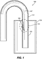
Fig. 1 is a cross-section view of an embodiment of a system in accordance with this disclosure; -
Fig. 2 is a cross-sectional, zoomed view of the embodiment ofFig. 1 , shown in a syphoning state; -
Fig. 3 is a cross-sectional zoomed view of a relief hole of the embodiment ofFig. 1 ; -
Fig. 4 is a cross-sectional view of the embodiment of the system ofFig. 1 , showing the tank filled with a liquid in a static state with even pressure; -
Fig. 5 is a cross-sectional view of the embodiment of the system ofFig. 1 , showing the tank in deaerator operation; and -
Fig. 6 is a cross-sectional view of the embodiment of the system ofFig. 1 , showing the tank in after deaerator operation where a high pressure differential exists. - Reference will now be made to the drawings wherein like reference numerals identify similar structural features or aspects of the subject disclosure. For purposes of explanation and illustration, and not limitation, an illustrative view of an embodiment of a system in accordance with the disclosure is shown in
Fig. 1 and is designated generally byreference character 100. Other embodiments and/or aspects of this disclosure are shown inFigs. 2-6 . - Referring to
Fig. 1 , adeaerator system 100 comprises atank vent tube 101. Thetank vent tube 101 for a deaerator tank system includes atube body 103 configured to mount to adeaerator tank 105 to be partially disposed within thedeaerator tank 105. The tube body defines avent channel 107. - Referring additionally to
Figs. 2 and3 , thetube 101 includes arelief hole 109 defined through thetube body 103. Thetube 101 includes aventuri structure 111 in thevent channel 107 of thetube body 103, e.g., at least partially over therelief hole 109. Theventuri structure 111 is configured to reduce pressure over therelief hole 109 as a function of flow (e.g., syphon flow as shown) in thevent channel 107. - The
venturi structure 111 can be defined by and integral with thetube body 103, for example. In certain embodiments, theventuri structure 111 can be a separate component placed in and/or attached to thetube body 103. - The
venturi structure 111 includeswall 113 extending across thevent channel 107. Thewall 113 defines aninlet 113a and anoutlet 113b between thewall 113 and aninterior surface 115 of thetube body 103. Theinlet 113a includes a larger flow area than theoutlet 113b. - In certain embodiments, the
wall 113 can include an angled or curved shape in a direction of flow to form a reducingchannel 117 between thewall 113 and theinterior surface 115 of thetube body 113. For example, thewall 113 can be an angled or curved plate, e.g., as shown. In certain embodiments, thewall 113 can be straight and theinterior wall 115 of thetube body 113 can be shaped to form the reducingchannel 117. The reducingchannel 117 can be linearly reducing and/or non-linearly reducing, for example. - In certain embodiments, the reducing
channel 117 can be about ten times as long as the distance across theinlet 113a (e.g., if square shaped inlet). In certain embodiments, theoutlet 113b can have about one fourth of the flow area of theinlet 113b. In certain embodiments, the position ofrelief hole 109 can be where the flow through the reducingchannel 117 is fastest. In certain embodiments, the reducingchannel 117 can include an area of constant flow area downstream of therelief hole 109. In certain embodiments, therelief hole 109 can be positioned at an area of constant flow area. Any suitable shape, position, and/or dimensions for theinlet 113a,outlet 113b, therelief hold 109 and the reducingchannel 117 is contemplated herein. - According to the present invention, the
inlet 113a is upstream of therelief hole 109. - The
tube 100 can include ascoop 119 extending from anouter surface 121 of thetube body 103 over therelief hole 109 to define arelief inlet channel 123. As shown, thescoop 119 can open downward with respect to a direction of gravity, for example. Thescoop 119 can aid in directionally orienting airflow and/or preventing splash of liquid into therelief hole 109, e.g., during deaerating. - As shown, in certain embodiments, the
tube body 103 can include a U-shape. Any other suitable shape is contemplated herein. Embodiments of atube 101 can be made by, e.g., investment casing, injection molding, additive manufacturing, machining, and/or any other suitable method. - In accordance with at least one aspect of this disclosure, a
deaerating system 100 can include adeaerator tank 105 configured to contain a liquid therein, and atank vent tube 101 disposed partially in thedeaerator tank 105. Thetank vent tube 101 can include any suitabletank vent tube 101 disclosed herein (e.g., as described above). - As shown in
Fig. 4 , in a static state, there is no pressure differential between the air in thetank 105 and the atmosphere (e.g., the vent location). As shown inFig. 5 , in deaerating, a cyclone is created and a high pressure forces air out through thetube 101. Any suitable embodiment of a deaerator system disclosed herein can be configured to cause a cyclone in the tank in any suitable manner as appreciated by those having ordinary skill in the art. As shown inFig. 6 , immediately after shut down, a high pressure head still exists such that there is a pressure differential causing a syphoning effect. However, the syphoning of liquid (e.g., oil) through theventuri structure 111, e.g., as shown inFig. 2 , creates a suction to more rapidly draw air out of the tank and equalize the pressure to prevent further suction. - In accordance with at least one aspect of this disclosure, a method of using the tube as described herein includes increasing speed of a flow in a tank vent tube over a relief hole in the tank vent tube to reduce pressure equalization time and reduce fluid loss through the vent tube. Any other suitable method and/or portion(s) thereof as appreciated by those having ordinary skill in the art in view of this disclosure are contemplated herein.
- Embodiments can include a venturi structure that depressurizes the tank quicker than traditional embodiments without the venturi structure. Embodiments may have no meaningful effect on normal operation of the deaerating system. Embodiments can quickly depressurize when liquid is syphoned through due to the venturi action and can provide minimal change in tank liquid level, e.g., after shut down. Certain embodiments can reduce oil loss by about 50% to about 75% of traditional systems.
- By adding a flow acceleration in the tube, a venturi effect will draw venting air quickly into the system, rapidly depressurizing the tank. Since such systems are more effective with liquid fluid flow, the venturi effect is improved. Such an effect is only meaningful when the syphon effect is taking place. When the tube is flowing air (e.g., typical operation for a deaerator), the venturi effect is reduced and air flow from the tank into the relief hole is minimal. This can prevent disruption of the proper function during operating when no fluid is flowing.
- Those having ordinary skill in the art understand that any numerical values disclosed herein can be exact values or can be values within a range. Further, any terms of approximation (e.g., "about", "approximately", "around") used in this disclosure can mean the stated value within a range. For example, in certain embodiments, the range can be within (plus or minus) 20%, or within 10%, or within 5%, or within 2%, or within any other suitable percentage or number as appreciated by those having ordinary skill in the art (e.g., for known tolerance limits or error ranges).
- Any suitable combination(s) of any disclosed embodiments and/or any suitable portion(s) thereof are contemplated herein as appreciated by those having ordinary skill in the art.
- The embodiments of the present disclosure, as described above and shown in the drawings, provide for improvement in the art to which they pertain. While the subject disclosure includes reference to certain embodiments, those skilled in the art will readily appreciate that changes and/or modifications may be made thereto without departing from the scope of the subject disclosure.
Claims (14)
- A tank vent tube (101) for a deaerator tank system, comprising:a tube body (103) configured to mount to a deaerator tank, the tube body defining a vent channel (107); anda relief hole (109) defined through the tube body (103); and characterised in that the tank vent tube (101) further comprisesa venturi structure (111) in the vent channel of the tube body (103) at least partially over the relief hole (109), wherein the venturi structure (111) is configured to reduce pressure over the relief hole (109) as a function of flow in the vent channel (107), wherein the venturi structure (111) includes a wall (113) extending across the vent channel (107), wherein the wall (113) defines an inlet (113a) and an outlet (113b) between the wall (113) and an interior surface of the tube body (103), wherein the inlet (113a) includes a larger flow area than the outlet (113b), wherein the inlet (113a) is upstream of the relief hole (109).
- The tube of claim 1, wherein the venturi structure is defined by and integral with the tube body.
- The tube of claim 1 or 2, wherein the wall includes an angled or curved shape in a direction of flow to form a reducing channel between the wall and the interior surface of the tube body.
- The tube of claim 3 wherein the wall includes an angled or curved plate.
- The tube of any preceding claim, further comprising a scoop extending from an outer surface of the tube body over the relief hole to define a relief inlet channel.
- The tube of claim 5, wherein the scoop opens downward with respect to a direction of gravity.
- The tube of any preceding claim, wherein the tube body includes a U-shape.
- A deaerating system (100), comprising:a deaerator tank (105)configured to contain a liquid therein; andthe tank vent tube (101) of claim 1 disposed partially in the deaerator tank, said tube body (101) being mounted to said deaerator tank and at least partially in the deaerator tank, the tube body defining a vent channel.
- The system of claim 8, wherein the venturi structure is defined by and integral with the tube body.
- The system of claim 8, wherein the wall includes an angled and/or curved shape in a direction of flow to form a reducing channel between the wall and the interior surface of the tube body.
- The system of claim 10, wherein the wall includes an angled or curved plate.
- The system of any of claims 8 to 11, further comprising a scoop extending from an outer surface of the tube body over the relief hole to define a relief inlet channel, and optionally wherein the scoop opens downward with respect to a direction of gravity.
- The system of any of claims 8 to 12, wherein the tube body includes a U-shape.
- A method of using the tube of claim 1, comprising:
increasing speed of a flow in the tank vent tube over the relief hole in the tank vent tube to reduce pressure equalization time and reduce fluid loss through the vent tube.
Applications Claiming Priority (1)
| Application Number | Priority Date | Filing Date | Title |
|---|---|---|---|
| US16/247,188 US11118540B2 (en) | 2019-01-14 | 2019-01-14 | Vented tank systems and components |
Publications (2)
| Publication Number | Publication Date |
|---|---|
| EP3683152A1 EP3683152A1 (en) | 2020-07-22 |
| EP3683152B1 true EP3683152B1 (en) | 2022-04-20 |
Family
ID=68731711
Family Applications (1)
| Application Number | Title | Priority Date | Filing Date |
|---|---|---|---|
| EP19211903.0A Active EP3683152B1 (en) | 2019-01-14 | 2019-11-27 | Vented tank systems and components |
Country Status (2)
| Country | Link |
|---|---|
| US (1) | US11118540B2 (en) |
| EP (1) | EP3683152B1 (en) |
Families Citing this family (1)
| Publication number | Priority date | Publication date | Assignee | Title |
|---|---|---|---|---|
| US12546345B2 (en) * | 2023-07-25 | 2026-02-10 | Textron Innovations Inc. | Auto-siphon drainage system for aircraft |
Citations (1)
| Publication number | Priority date | Publication date | Assignee | Title |
|---|---|---|---|---|
| US4668252A (en) * | 1984-12-11 | 1987-05-26 | Rotorcomp Verdichter Gmbh | Degasifier for a liquid separated from a gaseous fluid by a separator |
Family Cites Families (8)
| Publication number | Priority date | Publication date | Assignee | Title |
|---|---|---|---|---|
| US3239095A (en) * | 1964-03-02 | 1966-03-08 | J & J Steel And Supply Co Inc | Safety test tank |
| US3807465A (en) * | 1973-01-29 | 1974-04-30 | Standard Oil Co | Vapor recovery system and components therefor |
| US4538636A (en) | 1982-08-05 | 1985-09-03 | Cleland Robert K | Liquid aspirator with improved anti-syphon tube |
| US4892140A (en) * | 1988-11-21 | 1990-01-09 | Honovich Tito D | Condenser vent siphon line |
| US5247958A (en) * | 1990-05-11 | 1993-09-28 | Solvay & Cie | Safety valve, especially for a fuel tank vent pipe |
| US5244022A (en) | 1992-09-25 | 1993-09-14 | Borg-Warner Automotive, Inc. | Fuel flow activated fuel vapor control apparatus |
| DE10055355C2 (en) | 2000-11-08 | 2003-07-10 | Kautex Textron Gmbh & Co Kg | Fuel tank |
| DE102005053815A1 (en) | 2005-11-11 | 2007-05-24 | GM Global Technology Operations, Inc., Detroit | De-aeration unit for aerating and de-aerating e.g. liquid fuel tank, has supply port connected with activated carbon filter, and bypass line discharging fuel to de-aeration pipe, where throttle is provided in bypass line |
-
2019
- 2019-01-14 US US16/247,188 patent/US11118540B2/en active Active
- 2019-11-27 EP EP19211903.0A patent/EP3683152B1/en active Active
Patent Citations (1)
| Publication number | Priority date | Publication date | Assignee | Title |
|---|---|---|---|---|
| US4668252A (en) * | 1984-12-11 | 1987-05-26 | Rotorcomp Verdichter Gmbh | Degasifier for a liquid separated from a gaseous fluid by a separator |
Also Published As
| Publication number | Publication date |
|---|---|
| US20200224612A1 (en) | 2020-07-16 |
| EP3683152A1 (en) | 2020-07-22 |
| US11118540B2 (en) | 2021-09-14 |
Similar Documents
| Publication | Publication Date | Title |
|---|---|---|
| US3901245A (en) | Bio-medical pressure control device | |
| EP3683152B1 (en) | Vented tank systems and components | |
| SE441981B (en) | DEVICE AND PROCEDURE FOR SEPARING GAS FROM A FIBER SUSPENSION | |
| DE102011105891B4 (en) | Device for pressure-dependent opening of a suction opening and fuel tank | |
| US20100126589A1 (en) | Device for the prevention of high oil tank pressures under negative g conditions | |
| EP2157248B1 (en) | Drainage fittings with smell lock | |
| JPS622135B2 (en) | ||
| US9285045B2 (en) | Aircraft fuel tank vent protector | |
| US8998663B1 (en) | Methods of making and operating outboard motors | |
| DE102015216174A1 (en) | Hydraulic device for degassing a liquid | |
| EP4168714B1 (en) | A deaerator device | |
| US9927046B2 (en) | Throttling device | |
| DE102006051770B4 (en) | Active air separation system for automotive cooling systems | |
| CN207131573U (en) | Oil-gas separation device and screw compressor | |
| CN210739929U (en) | Jet drainage type lubricating oil filling device | |
| EP2817426A1 (en) | Pressure stabilization method | |
| US8298309B2 (en) | Liquid separator and tank system comprising a liquid separator | |
| CN112543842B (en) | Steam bypass inlet | |
| CN109707677B (en) | Hydraulic oil tank | |
| US20250297562A1 (en) | Oil deaerator device with reservoir provided with a stabilizing wall | |
| CN101718347A (en) | Design method of multi-orifice sleeve-type flow control valve and sleeve-type flow control valve | |
| CN211342838U (en) | Atmospheric deaerator | |
| DE2311383B1 (en) | Arrangement for reducing pressure increases and decreases in the writing fluid of an inkjet writing mechanism | |
| WO1999048104A1 (en) | Device and method for running off steam | |
| EP0363586A1 (en) | Gas separator |
Legal Events
| Date | Code | Title | Description |
|---|---|---|---|
| PUAI | Public reference made under article 153(3) epc to a published international application that has entered the european phase |
Free format text: ORIGINAL CODE: 0009012 |
|
| STAA | Information on the status of an ep patent application or granted ep patent |
Free format text: STATUS: THE APPLICATION HAS BEEN PUBLISHED |
|
| AK | Designated contracting states |
Kind code of ref document: A1 Designated state(s): AL AT BE BG CH CY CZ DE DK EE ES FI FR GB GR HR HU IE IS IT LI LT LU LV MC MK MT NL NO PL PT RO RS SE SI SK SM TR |
|
| AX | Request for extension of the european patent |
Extension state: BA ME |
|
| STAA | Information on the status of an ep patent application or granted ep patent |
Free format text: STATUS: REQUEST FOR EXAMINATION WAS MADE |
|
| 17P | Request for examination filed |
Effective date: 20210120 |
|
| RBV | Designated contracting states (corrected) |
Designated state(s): AL AT BE BG CH CY CZ DE DK EE ES FI FR GB GR HR HU IE IS IT LI LT LU LV MC MK MT NL NO PL PT RO RS SE SI SK SM TR |
|
| STAA | Information on the status of an ep patent application or granted ep patent |
Free format text: STATUS: EXAMINATION IS IN PROGRESS |
|
| 17Q | First examination report despatched |
Effective date: 20210224 |
|
| GRAP | Despatch of communication of intention to grant a patent |
Free format text: ORIGINAL CODE: EPIDOSNIGR1 |
|
| STAA | Information on the status of an ep patent application or granted ep patent |
Free format text: STATUS: GRANT OF PATENT IS INTENDED |
|
| INTG | Intention to grant announced |
Effective date: 20211105 |
|
| GRAS | Grant fee paid |
Free format text: ORIGINAL CODE: EPIDOSNIGR3 |
|
| GRAA | (expected) grant |
Free format text: ORIGINAL CODE: 0009210 |
|
| STAA | Information on the status of an ep patent application or granted ep patent |
Free format text: STATUS: THE PATENT HAS BEEN GRANTED |
|
| AK | Designated contracting states |
Kind code of ref document: B1 Designated state(s): AL AT BE BG CH CY CZ DE DK EE ES FI FR GB GR HR HU IE IS IT LI LT LU LV MC MK MT NL NO PL PT RO RS SE SI SK SM TR |
|
| REG | Reference to a national code |
Ref country code: GB Ref legal event code: FG4D |
|
| REG | Reference to a national code |
Ref country code: CH Ref legal event code: EP |
|
| REG | Reference to a national code |
Ref country code: IE Ref legal event code: FG4D |
|
| REG | Reference to a national code |
Ref country code: DE Ref legal event code: R096 Ref document number: 602019013877 Country of ref document: DE |
|
| REG | Reference to a national code |
Ref country code: AT Ref legal event code: REF Ref document number: 1484996 Country of ref document: AT Kind code of ref document: T Effective date: 20220515 |
|
| REG | Reference to a national code |
Ref country code: LT Ref legal event code: MG9D |
|
| REG | Reference to a national code |
Ref country code: NL Ref legal event code: MP Effective date: 20220420 |
|
| REG | Reference to a national code |
Ref country code: AT Ref legal event code: MK05 Ref document number: 1484996 Country of ref document: AT Kind code of ref document: T Effective date: 20220420 |
|
| PG25 | Lapsed in a contracting state [announced via postgrant information from national office to epo] |
Ref country code: NL Free format text: LAPSE BECAUSE OF FAILURE TO SUBMIT A TRANSLATION OF THE DESCRIPTION OR TO PAY THE FEE WITHIN THE PRESCRIBED TIME-LIMIT Effective date: 20220420 |
|
| PG25 | Lapsed in a contracting state [announced via postgrant information from national office to epo] |
Ref country code: SE Free format text: LAPSE BECAUSE OF FAILURE TO SUBMIT A TRANSLATION OF THE DESCRIPTION OR TO PAY THE FEE WITHIN THE PRESCRIBED TIME-LIMIT Effective date: 20220420 Ref country code: PT Free format text: LAPSE BECAUSE OF FAILURE TO SUBMIT A TRANSLATION OF THE DESCRIPTION OR TO PAY THE FEE WITHIN THE PRESCRIBED TIME-LIMIT Effective date: 20220822 Ref country code: NO Free format text: LAPSE BECAUSE OF FAILURE TO SUBMIT A TRANSLATION OF THE DESCRIPTION OR TO PAY THE FEE WITHIN THE PRESCRIBED TIME-LIMIT Effective date: 20220720 Ref country code: LT Free format text: LAPSE BECAUSE OF FAILURE TO SUBMIT A TRANSLATION OF THE DESCRIPTION OR TO PAY THE FEE WITHIN THE PRESCRIBED TIME-LIMIT Effective date: 20220420 Ref country code: HR Free format text: LAPSE BECAUSE OF FAILURE TO SUBMIT A TRANSLATION OF THE DESCRIPTION OR TO PAY THE FEE WITHIN THE PRESCRIBED TIME-LIMIT Effective date: 20220420 Ref country code: GR Free format text: LAPSE BECAUSE OF FAILURE TO SUBMIT A TRANSLATION OF THE DESCRIPTION OR TO PAY THE FEE WITHIN THE PRESCRIBED TIME-LIMIT Effective date: 20220721 Ref country code: FI Free format text: LAPSE BECAUSE OF FAILURE TO SUBMIT A TRANSLATION OF THE DESCRIPTION OR TO PAY THE FEE WITHIN THE PRESCRIBED TIME-LIMIT Effective date: 20220420 Ref country code: ES Free format text: LAPSE BECAUSE OF FAILURE TO SUBMIT A TRANSLATION OF THE DESCRIPTION OR TO PAY THE FEE WITHIN THE PRESCRIBED TIME-LIMIT Effective date: 20220420 Ref country code: BG Free format text: LAPSE BECAUSE OF FAILURE TO SUBMIT A TRANSLATION OF THE DESCRIPTION OR TO PAY THE FEE WITHIN THE PRESCRIBED TIME-LIMIT Effective date: 20220720 Ref country code: AT Free format text: LAPSE BECAUSE OF FAILURE TO SUBMIT A TRANSLATION OF THE DESCRIPTION OR TO PAY THE FEE WITHIN THE PRESCRIBED TIME-LIMIT Effective date: 20220420 |
|
| PG25 | Lapsed in a contracting state [announced via postgrant information from national office to epo] |
Ref country code: RS Free format text: LAPSE BECAUSE OF FAILURE TO SUBMIT A TRANSLATION OF THE DESCRIPTION OR TO PAY THE FEE WITHIN THE PRESCRIBED TIME-LIMIT Effective date: 20220420 Ref country code: PL Free format text: LAPSE BECAUSE OF FAILURE TO SUBMIT A TRANSLATION OF THE DESCRIPTION OR TO PAY THE FEE WITHIN THE PRESCRIBED TIME-LIMIT Effective date: 20220420 Ref country code: LV Free format text: LAPSE BECAUSE OF FAILURE TO SUBMIT A TRANSLATION OF THE DESCRIPTION OR TO PAY THE FEE WITHIN THE PRESCRIBED TIME-LIMIT Effective date: 20220420 Ref country code: IS Free format text: LAPSE BECAUSE OF FAILURE TO SUBMIT A TRANSLATION OF THE DESCRIPTION OR TO PAY THE FEE WITHIN THE PRESCRIBED TIME-LIMIT Effective date: 20220820 |
|
| REG | Reference to a national code |
Ref country code: DE Ref legal event code: R097 Ref document number: 602019013877 Country of ref document: DE |
|
| PG25 | Lapsed in a contracting state [announced via postgrant information from national office to epo] |
Ref country code: SM Free format text: LAPSE BECAUSE OF FAILURE TO SUBMIT A TRANSLATION OF THE DESCRIPTION OR TO PAY THE FEE WITHIN THE PRESCRIBED TIME-LIMIT Effective date: 20220420 Ref country code: SK Free format text: LAPSE BECAUSE OF FAILURE TO SUBMIT A TRANSLATION OF THE DESCRIPTION OR TO PAY THE FEE WITHIN THE PRESCRIBED TIME-LIMIT Effective date: 20220420 Ref country code: RO Free format text: LAPSE BECAUSE OF FAILURE TO SUBMIT A TRANSLATION OF THE DESCRIPTION OR TO PAY THE FEE WITHIN THE PRESCRIBED TIME-LIMIT Effective date: 20220420 Ref country code: EE Free format text: LAPSE BECAUSE OF FAILURE TO SUBMIT A TRANSLATION OF THE DESCRIPTION OR TO PAY THE FEE WITHIN THE PRESCRIBED TIME-LIMIT Effective date: 20220420 Ref country code: DK Free format text: LAPSE BECAUSE OF FAILURE TO SUBMIT A TRANSLATION OF THE DESCRIPTION OR TO PAY THE FEE WITHIN THE PRESCRIBED TIME-LIMIT Effective date: 20220420 Ref country code: CZ Free format text: LAPSE BECAUSE OF FAILURE TO SUBMIT A TRANSLATION OF THE DESCRIPTION OR TO PAY THE FEE WITHIN THE PRESCRIBED TIME-LIMIT Effective date: 20220420 |
|
| PLBE | No opposition filed within time limit |
Free format text: ORIGINAL CODE: 0009261 |
|
| STAA | Information on the status of an ep patent application or granted ep patent |
Free format text: STATUS: NO OPPOSITION FILED WITHIN TIME LIMIT |
|
| 26N | No opposition filed |
Effective date: 20230123 |
|
| PG25 | Lapsed in a contracting state [announced via postgrant information from national office to epo] |
Ref country code: AL Free format text: LAPSE BECAUSE OF FAILURE TO SUBMIT A TRANSLATION OF THE DESCRIPTION OR TO PAY THE FEE WITHIN THE PRESCRIBED TIME-LIMIT Effective date: 20220420 |
|
| PG25 | Lapsed in a contracting state [announced via postgrant information from national office to epo] |
Ref country code: SI Free format text: LAPSE BECAUSE OF FAILURE TO SUBMIT A TRANSLATION OF THE DESCRIPTION OR TO PAY THE FEE WITHIN THE PRESCRIBED TIME-LIMIT Effective date: 20220420 |
|
| PG25 | Lapsed in a contracting state [announced via postgrant information from national office to epo] |
Ref country code: MC Free format text: LAPSE BECAUSE OF FAILURE TO SUBMIT A TRANSLATION OF THE DESCRIPTION OR TO PAY THE FEE WITHIN THE PRESCRIBED TIME-LIMIT Effective date: 20220420 |
|
| REG | Reference to a national code |
Ref country code: CH Ref legal event code: PL |
|
| P01 | Opt-out of the competence of the unified patent court (upc) registered |
Effective date: 20230603 |
|
| REG | Reference to a national code |
Ref country code: BE Ref legal event code: MM Effective date: 20221130 |
|
| PG25 | Lapsed in a contracting state [announced via postgrant information from national office to epo] |
Ref country code: LI Free format text: LAPSE BECAUSE OF NON-PAYMENT OF DUE FEES Effective date: 20221130 Ref country code: CH Free format text: LAPSE BECAUSE OF NON-PAYMENT OF DUE FEES Effective date: 20221130 |
|
| PG25 | Lapsed in a contracting state [announced via postgrant information from national office to epo] |
Ref country code: LU Free format text: LAPSE BECAUSE OF NON-PAYMENT OF DUE FEES Effective date: 20221127 |
|
| PG25 | Lapsed in a contracting state [announced via postgrant information from national office to epo] |
Ref country code: IE Free format text: LAPSE BECAUSE OF NON-PAYMENT OF DUE FEES Effective date: 20221127 |
|
| PG25 | Lapsed in a contracting state [announced via postgrant information from national office to epo] |
Ref country code: BE Free format text: LAPSE BECAUSE OF NON-PAYMENT OF DUE FEES Effective date: 20221130 |
|
| PG25 | Lapsed in a contracting state [announced via postgrant information from national office to epo] |
Ref country code: IT Free format text: LAPSE BECAUSE OF FAILURE TO SUBMIT A TRANSLATION OF THE DESCRIPTION OR TO PAY THE FEE WITHIN THE PRESCRIBED TIME-LIMIT Effective date: 20220420 |
|
| PG25 | Lapsed in a contracting state [announced via postgrant information from national office to epo] |
Ref country code: HU Free format text: LAPSE BECAUSE OF FAILURE TO SUBMIT A TRANSLATION OF THE DESCRIPTION OR TO PAY THE FEE WITHIN THE PRESCRIBED TIME-LIMIT; INVALID AB INITIO Effective date: 20191127 |
|
| PG25 | Lapsed in a contracting state [announced via postgrant information from national office to epo] |
Ref country code: CY Free format text: LAPSE BECAUSE OF FAILURE TO SUBMIT A TRANSLATION OF THE DESCRIPTION OR TO PAY THE FEE WITHIN THE PRESCRIBED TIME-LIMIT Effective date: 20220420 |
|
| PG25 | Lapsed in a contracting state [announced via postgrant information from national office to epo] |
Ref country code: MK Free format text: LAPSE BECAUSE OF FAILURE TO SUBMIT A TRANSLATION OF THE DESCRIPTION OR TO PAY THE FEE WITHIN THE PRESCRIBED TIME-LIMIT Effective date: 20220420 |
|
| PG25 | Lapsed in a contracting state [announced via postgrant information from national office to epo] |
Ref country code: TR Free format text: LAPSE BECAUSE OF FAILURE TO SUBMIT A TRANSLATION OF THE DESCRIPTION OR TO PAY THE FEE WITHIN THE PRESCRIBED TIME-LIMIT Effective date: 20220420 |
|
| PG25 | Lapsed in a contracting state [announced via postgrant information from national office to epo] |
Ref country code: MT Free format text: LAPSE BECAUSE OF FAILURE TO SUBMIT A TRANSLATION OF THE DESCRIPTION OR TO PAY THE FEE WITHIN THE PRESCRIBED TIME-LIMIT Effective date: 20220420 |
|
| PG25 | Lapsed in a contracting state [announced via postgrant information from national office to epo] |
Ref country code: BG Free format text: LAPSE BECAUSE OF FAILURE TO SUBMIT A TRANSLATION OF THE DESCRIPTION OR TO PAY THE FEE WITHIN THE PRESCRIBED TIME-LIMIT Effective date: 20220420 |
|
| PG25 | Lapsed in a contracting state [announced via postgrant information from national office to epo] |
Ref country code: BG Free format text: LAPSE BECAUSE OF FAILURE TO SUBMIT A TRANSLATION OF THE DESCRIPTION OR TO PAY THE FEE WITHIN THE PRESCRIBED TIME-LIMIT Effective date: 20220420 |
|
| PGFP | Annual fee paid to national office [announced via postgrant information from national office to epo] |
Ref country code: DE Payment date: 20251022 Year of fee payment: 7 |
|
| PGFP | Annual fee paid to national office [announced via postgrant information from national office to epo] |
Ref country code: GB Payment date: 20251023 Year of fee payment: 7 |
|
| PGFP | Annual fee paid to national office [announced via postgrant information from national office to epo] |
Ref country code: FR Payment date: 20251023 Year of fee payment: 7 |