EP3683078B1 - Control system to eliminate powertrain backlash - Google Patents
Control system to eliminate powertrain backlash Download PDFInfo
- Publication number
- EP3683078B1 EP3683078B1 EP20151208.4A EP20151208A EP3683078B1 EP 3683078 B1 EP3683078 B1 EP 3683078B1 EP 20151208 A EP20151208 A EP 20151208A EP 3683078 B1 EP3683078 B1 EP 3683078B1
- Authority
- EP
- European Patent Office
- Prior art keywords
- torque
- powertrain
- vehicle
- reverse
- motor
- Prior art date
- Legal status (The legal status is an assumption and is not a legal conclusion. Google has not performed a legal analysis and makes no representation as to the accuracy of the status listed.)
- Active
Links
Images



Classifications
-
- B—PERFORMING OPERATIONS; TRANSPORTING
- B60—VEHICLES IN GENERAL
- B60L—PROPULSION OF ELECTRICALLY-PROPELLED VEHICLES; SUPPLYING ELECTRIC POWER FOR AUXILIARY EQUIPMENT OF ELECTRICALLY-PROPELLED VEHICLES; ELECTRODYNAMIC BRAKE SYSTEMS FOR VEHICLES IN GENERAL; MAGNETIC SUSPENSION OR LEVITATION FOR VEHICLES; MONITORING OPERATING VARIABLES OF ELECTRICALLY-PROPELLED VEHICLES; ELECTRIC SAFETY DEVICES FOR ELECTRICALLY-PROPELLED VEHICLES
- B60L15/00—Methods, circuits, or devices for controlling the traction-motor speed of electrically-propelled vehicles
- B60L15/32—Control or regulation of multiple-unit electrically-propelled vehicles
- B60L15/34—Control or regulation of multiple-unit electrically-propelled vehicles with human control of a setting device
-
- B—PERFORMING OPERATIONS; TRANSPORTING
- B60—VEHICLES IN GENERAL
- B60W—CONJOINT CONTROL OF VEHICLE SUB-UNITS OF DIFFERENT TYPE OR DIFFERENT FUNCTION; CONTROL SYSTEMS SPECIALLY ADAPTED FOR HYBRID VEHICLES; ROAD VEHICLE DRIVE CONTROL SYSTEMS FOR PURPOSES NOT RELATED TO THE CONTROL OF A PARTICULAR SUB-UNIT
- B60W30/00—Purposes of road vehicle drive control systems not related to the control of a particular sub-unit, e.g. of systems using conjoint control of vehicle sub-units
- B60W30/18—Propelling the vehicle
- B60W30/20—Reducing vibrations in the driveline
-
- B—PERFORMING OPERATIONS; TRANSPORTING
- B60—VEHICLES IN GENERAL
- B60K—ARRANGEMENT OR MOUNTING OF PROPULSION UNITS OR OF TRANSMISSIONS IN VEHICLES; ARRANGEMENT OR MOUNTING OF PLURAL DIVERSE PRIME-MOVERS IN VEHICLES; AUXILIARY DRIVES FOR VEHICLES; INSTRUMENTATION OR DASHBOARDS FOR VEHICLES; ARRANGEMENTS IN CONNECTION WITH COOLING, AIR INTAKE, GAS EXHAUST OR FUEL SUPPLY OF PROPULSION UNITS IN VEHICLES
- B60K1/00—Arrangement or mounting of electrical propulsion units
-
- B—PERFORMING OPERATIONS; TRANSPORTING
- B60—VEHICLES IN GENERAL
- B60K—ARRANGEMENT OR MOUNTING OF PROPULSION UNITS OR OF TRANSMISSIONS IN VEHICLES; ARRANGEMENT OR MOUNTING OF PLURAL DIVERSE PRIME-MOVERS IN VEHICLES; AUXILIARY DRIVES FOR VEHICLES; INSTRUMENTATION OR DASHBOARDS FOR VEHICLES; ARRANGEMENTS IN CONNECTION WITH COOLING, AIR INTAKE, GAS EXHAUST OR FUEL SUPPLY OF PROPULSION UNITS IN VEHICLES
- B60K17/00—Arrangement or mounting of transmissions in vehicles
- B60K17/34—Arrangement or mounting of transmissions in vehicles for driving both front and rear wheels, e.g. four wheel drive vehicles
- B60K17/354—Arrangement or mounting of transmissions in vehicles for driving both front and rear wheels, e.g. four wheel drive vehicles having separate mechanical assemblies for transmitting drive to the front or to the rear wheels or set of wheels
-
- B—PERFORMING OPERATIONS; TRANSPORTING
- B60—VEHICLES IN GENERAL
- B60K—ARRANGEMENT OR MOUNTING OF PROPULSION UNITS OR OF TRANSMISSIONS IN VEHICLES; ARRANGEMENT OR MOUNTING OF PLURAL DIVERSE PRIME-MOVERS IN VEHICLES; AUXILIARY DRIVES FOR VEHICLES; INSTRUMENTATION OR DASHBOARDS FOR VEHICLES; ARRANGEMENTS IN CONNECTION WITH COOLING, AIR INTAKE, GAS EXHAUST OR FUEL SUPPLY OF PROPULSION UNITS IN VEHICLES
- B60K17/00—Arrangement or mounting of transmissions in vehicles
- B60K17/34—Arrangement or mounting of transmissions in vehicles for driving both front and rear wheels, e.g. four wheel drive vehicles
- B60K17/356—Arrangement or mounting of transmissions in vehicles for driving both front and rear wheels, e.g. four wheel drive vehicles having fluid or electric motor, for driving one or more wheels
-
- B—PERFORMING OPERATIONS; TRANSPORTING
- B60—VEHICLES IN GENERAL
- B60K—ARRANGEMENT OR MOUNTING OF PROPULSION UNITS OR OF TRANSMISSIONS IN VEHICLES; ARRANGEMENT OR MOUNTING OF PLURAL DIVERSE PRIME-MOVERS IN VEHICLES; AUXILIARY DRIVES FOR VEHICLES; INSTRUMENTATION OR DASHBOARDS FOR VEHICLES; ARRANGEMENTS IN CONNECTION WITH COOLING, AIR INTAKE, GAS EXHAUST OR FUEL SUPPLY OF PROPULSION UNITS IN VEHICLES
- B60K7/00—Disposition of motor in, or adjacent to, traction wheel
- B60K7/0007—Disposition of motor in, or adjacent to, traction wheel the motor being electric
-
- B—PERFORMING OPERATIONS; TRANSPORTING
- B60—VEHICLES IN GENERAL
- B60L—PROPULSION OF ELECTRICALLY-PROPELLED VEHICLES; SUPPLYING ELECTRIC POWER FOR AUXILIARY EQUIPMENT OF ELECTRICALLY-PROPELLED VEHICLES; ELECTRODYNAMIC BRAKE SYSTEMS FOR VEHICLES IN GENERAL; MAGNETIC SUSPENSION OR LEVITATION FOR VEHICLES; MONITORING OPERATING VARIABLES OF ELECTRICALLY-PROPELLED VEHICLES; ELECTRIC SAFETY DEVICES FOR ELECTRICALLY-PROPELLED VEHICLES
- B60L15/00—Methods, circuits, or devices for controlling the traction-motor speed of electrically-propelled vehicles
- B60L15/20—Methods, circuits, or devices for controlling the traction-motor speed of electrically-propelled vehicles for control of the vehicle or its driving motor to achieve a desired performance, e.g. speed, torque, programmed variation of speed
-
- B—PERFORMING OPERATIONS; TRANSPORTING
- B60—VEHICLES IN GENERAL
- B60W—CONJOINT CONTROL OF VEHICLE SUB-UNITS OF DIFFERENT TYPE OR DIFFERENT FUNCTION; CONTROL SYSTEMS SPECIALLY ADAPTED FOR HYBRID VEHICLES; ROAD VEHICLE DRIVE CONTROL SYSTEMS FOR PURPOSES NOT RELATED TO THE CONTROL OF A PARTICULAR SUB-UNIT
- B60W10/00—Conjoint control of vehicle sub-units of different type or different function
- B60W10/04—Conjoint control of vehicle sub-units of different type or different function including control of propulsion units
- B60W10/08—Conjoint control of vehicle sub-units of different type or different function including control of propulsion units including control of electric propulsion units, e.g. motors or generators
-
- B—PERFORMING OPERATIONS; TRANSPORTING
- B60—VEHICLES IN GENERAL
- B60W—CONJOINT CONTROL OF VEHICLE SUB-UNITS OF DIFFERENT TYPE OR DIFFERENT FUNCTION; CONTROL SYSTEMS SPECIALLY ADAPTED FOR HYBRID VEHICLES; ROAD VEHICLE DRIVE CONTROL SYSTEMS FOR PURPOSES NOT RELATED TO THE CONTROL OF A PARTICULAR SUB-UNIT
- B60W10/00—Conjoint control of vehicle sub-units of different type or different function
- B60W10/10—Conjoint control of vehicle sub-units of different type or different function including control of change-speed gearings
-
- B—PERFORMING OPERATIONS; TRANSPORTING
- B60—VEHICLES IN GENERAL
- B60W—CONJOINT CONTROL OF VEHICLE SUB-UNITS OF DIFFERENT TYPE OR DIFFERENT FUNCTION; CONTROL SYSTEMS SPECIALLY ADAPTED FOR HYBRID VEHICLES; ROAD VEHICLE DRIVE CONTROL SYSTEMS FOR PURPOSES NOT RELATED TO THE CONTROL OF A PARTICULAR SUB-UNIT
- B60W30/00—Purposes of road vehicle drive control systems not related to the control of a particular sub-unit, e.g. of systems using conjoint control of vehicle sub-units
- B60W30/18—Propelling the vehicle
- B60W30/188—Controlling power parameters of the driveline, e.g. determining the required power
-
- B—PERFORMING OPERATIONS; TRANSPORTING
- B60—VEHICLES IN GENERAL
- B60W—CONJOINT CONTROL OF VEHICLE SUB-UNITS OF DIFFERENT TYPE OR DIFFERENT FUNCTION; CONTROL SYSTEMS SPECIALLY ADAPTED FOR HYBRID VEHICLES; ROAD VEHICLE DRIVE CONTROL SYSTEMS FOR PURPOSES NOT RELATED TO THE CONTROL OF A PARTICULAR SUB-UNIT
- B60W40/00—Estimation or calculation of non-directly measurable driving parameters for road vehicle drive control systems not related to the control of a particular sub unit, e.g. by using mathematical models
- B60W40/10—Estimation or calculation of non-directly measurable driving parameters for road vehicle drive control systems not related to the control of a particular sub unit, e.g. by using mathematical models related to vehicle motion
- B60W40/105—Speed
-
- F—MECHANICAL ENGINEERING; LIGHTING; HEATING; WEAPONS; BLASTING
- F16—ENGINEERING ELEMENTS AND UNITS; GENERAL MEASURES FOR PRODUCING AND MAINTAINING EFFECTIVE FUNCTIONING OF MACHINES OR INSTALLATIONS; THERMAL INSULATION IN GENERAL
- F16H—GEARING
- F16H57/00—General details of gearing
- F16H57/0006—Vibration-damping or noise reducing means specially adapted for gearings
-
- F—MECHANICAL ENGINEERING; LIGHTING; HEATING; WEAPONS; BLASTING
- F16—ENGINEERING ELEMENTS AND UNITS; GENERAL MEASURES FOR PRODUCING AND MAINTAINING EFFECTIVE FUNCTIONING OF MACHINES OR INSTALLATIONS; THERMAL INSULATION IN GENERAL
- F16H—GEARING
- F16H57/00—General details of gearing
- F16H57/12—Arrangements for adjusting or for taking-up backlash not provided for elsewhere
-
- B—PERFORMING OPERATIONS; TRANSPORTING
- B60—VEHICLES IN GENERAL
- B60K—ARRANGEMENT OR MOUNTING OF PROPULSION UNITS OR OF TRANSMISSIONS IN VEHICLES; ARRANGEMENT OR MOUNTING OF PLURAL DIVERSE PRIME-MOVERS IN VEHICLES; AUXILIARY DRIVES FOR VEHICLES; INSTRUMENTATION OR DASHBOARDS FOR VEHICLES; ARRANGEMENTS IN CONNECTION WITH COOLING, AIR INTAKE, GAS EXHAUST OR FUEL SUPPLY OF PROPULSION UNITS IN VEHICLES
- B60K17/00—Arrangement or mounting of transmissions in vehicles
- B60K17/04—Arrangement or mounting of transmissions in vehicles characterised by arrangement, location or kind of gearing
- B60K17/043—Transmission unit disposed in on near the vehicle wheel, or between the differential gear unit and the wheel
-
- B—PERFORMING OPERATIONS; TRANSPORTING
- B60—VEHICLES IN GENERAL
- B60K—ARRANGEMENT OR MOUNTING OF PROPULSION UNITS OR OF TRANSMISSIONS IN VEHICLES; ARRANGEMENT OR MOUNTING OF PLURAL DIVERSE PRIME-MOVERS IN VEHICLES; AUXILIARY DRIVES FOR VEHICLES; INSTRUMENTATION OR DASHBOARDS FOR VEHICLES; ARRANGEMENTS IN CONNECTION WITH COOLING, AIR INTAKE, GAS EXHAUST OR FUEL SUPPLY OF PROPULSION UNITS IN VEHICLES
- B60K1/00—Arrangement or mounting of electrical propulsion units
- B60K2001/001—Arrangement or mounting of electrical propulsion units one motor mounted on a propulsion axle for rotating right and left wheels of this axle
-
- B—PERFORMING OPERATIONS; TRANSPORTING
- B60—VEHICLES IN GENERAL
- B60K—ARRANGEMENT OR MOUNTING OF PROPULSION UNITS OR OF TRANSMISSIONS IN VEHICLES; ARRANGEMENT OR MOUNTING OF PLURAL DIVERSE PRIME-MOVERS IN VEHICLES; AUXILIARY DRIVES FOR VEHICLES; INSTRUMENTATION OR DASHBOARDS FOR VEHICLES; ARRANGEMENTS IN CONNECTION WITH COOLING, AIR INTAKE, GAS EXHAUST OR FUEL SUPPLY OF PROPULSION UNITS IN VEHICLES
- B60K7/00—Disposition of motor in, or adjacent to, traction wheel
- B60K2007/0038—Disposition of motor in, or adjacent to, traction wheel the motor moving together with the wheel axle
-
- B—PERFORMING OPERATIONS; TRANSPORTING
- B60—VEHICLES IN GENERAL
- B60K—ARRANGEMENT OR MOUNTING OF PROPULSION UNITS OR OF TRANSMISSIONS IN VEHICLES; ARRANGEMENT OR MOUNTING OF PLURAL DIVERSE PRIME-MOVERS IN VEHICLES; AUXILIARY DRIVES FOR VEHICLES; INSTRUMENTATION OR DASHBOARDS FOR VEHICLES; ARRANGEMENTS IN CONNECTION WITH COOLING, AIR INTAKE, GAS EXHAUST OR FUEL SUPPLY OF PROPULSION UNITS IN VEHICLES
- B60K7/00—Disposition of motor in, or adjacent to, traction wheel
- B60K2007/0061—Disposition of motor in, or adjacent to, traction wheel the motor axle being parallel to the wheel axle
-
- B—PERFORMING OPERATIONS; TRANSPORTING
- B60—VEHICLES IN GENERAL
- B60K—ARRANGEMENT OR MOUNTING OF PROPULSION UNITS OR OF TRANSMISSIONS IN VEHICLES; ARRANGEMENT OR MOUNTING OF PLURAL DIVERSE PRIME-MOVERS IN VEHICLES; AUXILIARY DRIVES FOR VEHICLES; INSTRUMENTATION OR DASHBOARDS FOR VEHICLES; ARRANGEMENTS IN CONNECTION WITH COOLING, AIR INTAKE, GAS EXHAUST OR FUEL SUPPLY OF PROPULSION UNITS IN VEHICLES
- B60K6/00—Arrangement or mounting of plural diverse prime-movers for mutual or common propulsion, e.g. hybrid propulsion systems comprising electric motors and internal combustion engines
- B60K6/20—Arrangement or mounting of plural diverse prime-movers for mutual or common propulsion, e.g. hybrid propulsion systems comprising electric motors and internal combustion engines the prime-movers consisting of electric motors and internal combustion engines, e.g. HEVs
- B60K6/22—Arrangement or mounting of plural diverse prime-movers for mutual or common propulsion, e.g. hybrid propulsion systems comprising electric motors and internal combustion engines the prime-movers consisting of electric motors and internal combustion engines, e.g. HEVs characterised by apparatus, components or means specially adapted for HEVs
- B60K6/26—Arrangement or mounting of plural diverse prime-movers for mutual or common propulsion, e.g. hybrid propulsion systems comprising electric motors and internal combustion engines the prime-movers consisting of electric motors and internal combustion engines, e.g. HEVs characterised by apparatus, components or means specially adapted for HEVs characterised by the motors or the generators
-
- B—PERFORMING OPERATIONS; TRANSPORTING
- B60—VEHICLES IN GENERAL
- B60L—PROPULSION OF ELECTRICALLY-PROPELLED VEHICLES; SUPPLYING ELECTRIC POWER FOR AUXILIARY EQUIPMENT OF ELECTRICALLY-PROPELLED VEHICLES; ELECTRODYNAMIC BRAKE SYSTEMS FOR VEHICLES IN GENERAL; MAGNETIC SUSPENSION OR LEVITATION FOR VEHICLES; MONITORING OPERATING VARIABLES OF ELECTRICALLY-PROPELLED VEHICLES; ELECTRIC SAFETY DEVICES FOR ELECTRICALLY-PROPELLED VEHICLES
- B60L15/00—Methods, circuits, or devices for controlling the traction-motor speed of electrically-propelled vehicles
-
- B—PERFORMING OPERATIONS; TRANSPORTING
- B60—VEHICLES IN GENERAL
- B60L—PROPULSION OF ELECTRICALLY-PROPELLED VEHICLES; SUPPLYING ELECTRIC POWER FOR AUXILIARY EQUIPMENT OF ELECTRICALLY-PROPELLED VEHICLES; ELECTRODYNAMIC BRAKE SYSTEMS FOR VEHICLES IN GENERAL; MAGNETIC SUSPENSION OR LEVITATION FOR VEHICLES; MONITORING OPERATING VARIABLES OF ELECTRICALLY-PROPELLED VEHICLES; ELECTRIC SAFETY DEVICES FOR ELECTRICALLY-PROPELLED VEHICLES
- B60L2240/00—Control parameters of input or output; Target parameters
- B60L2240/10—Vehicle control parameters
- B60L2240/32—Driving direction
-
- B—PERFORMING OPERATIONS; TRANSPORTING
- B60—VEHICLES IN GENERAL
- B60L—PROPULSION OF ELECTRICALLY-PROPELLED VEHICLES; SUPPLYING ELECTRIC POWER FOR AUXILIARY EQUIPMENT OF ELECTRICALLY-PROPELLED VEHICLES; ELECTRODYNAMIC BRAKE SYSTEMS FOR VEHICLES IN GENERAL; MAGNETIC SUSPENSION OR LEVITATION FOR VEHICLES; MONITORING OPERATING VARIABLES OF ELECTRICALLY-PROPELLED VEHICLES; ELECTRIC SAFETY DEVICES FOR ELECTRICALLY-PROPELLED VEHICLES
- B60L2240/00—Control parameters of input or output; Target parameters
- B60L2240/40—Drive Train control parameters
- B60L2240/42—Drive Train control parameters related to electric machines
- B60L2240/423—Torque
-
- B—PERFORMING OPERATIONS; TRANSPORTING
- B60—VEHICLES IN GENERAL
- B60W—CONJOINT CONTROL OF VEHICLE SUB-UNITS OF DIFFERENT TYPE OR DIFFERENT FUNCTION; CONTROL SYSTEMS SPECIALLY ADAPTED FOR HYBRID VEHICLES; ROAD VEHICLE DRIVE CONTROL SYSTEMS FOR PURPOSES NOT RELATED TO THE CONTROL OF A PARTICULAR SUB-UNIT
- B60W2520/00—Input parameters relating to overall vehicle dynamics
- B60W2520/10—Longitudinal speed
-
- B—PERFORMING OPERATIONS; TRANSPORTING
- B60—VEHICLES IN GENERAL
- B60W—CONJOINT CONTROL OF VEHICLE SUB-UNITS OF DIFFERENT TYPE OR DIFFERENT FUNCTION; CONTROL SYSTEMS SPECIALLY ADAPTED FOR HYBRID VEHICLES; ROAD VEHICLE DRIVE CONTROL SYSTEMS FOR PURPOSES NOT RELATED TO THE CONTROL OF A PARTICULAR SUB-UNIT
- B60W2540/00—Input parameters relating to occupants
- B60W2540/10—Accelerator pedal position
-
- B—PERFORMING OPERATIONS; TRANSPORTING
- B60—VEHICLES IN GENERAL
- B60W—CONJOINT CONTROL OF VEHICLE SUB-UNITS OF DIFFERENT TYPE OR DIFFERENT FUNCTION; CONTROL SYSTEMS SPECIALLY ADAPTED FOR HYBRID VEHICLES; ROAD VEHICLE DRIVE CONTROL SYSTEMS FOR PURPOSES NOT RELATED TO THE CONTROL OF A PARTICULAR SUB-UNIT
- B60W2710/00—Output or target parameters relating to a particular sub-units
- B60W2710/08—Electric propulsion units
- B60W2710/083—Torque
-
- B—PERFORMING OPERATIONS; TRANSPORTING
- B60—VEHICLES IN GENERAL
- B60Y—INDEXING SCHEME RELATING TO ASPECTS CROSS-CUTTING VEHICLE TECHNOLOGY
- B60Y2200/00—Type of vehicle
- B60Y2200/90—Vehicles comprising electric prime movers
- B60Y2200/91—Electric vehicles
-
- B—PERFORMING OPERATIONS; TRANSPORTING
- B60—VEHICLES IN GENERAL
- B60Y—INDEXING SCHEME RELATING TO ASPECTS CROSS-CUTTING VEHICLE TECHNOLOGY
- B60Y2200/00—Type of vehicle
- B60Y2200/90—Vehicles comprising electric prime movers
- B60Y2200/92—Hybrid vehicles
-
- B—PERFORMING OPERATIONS; TRANSPORTING
- B60—VEHICLES IN GENERAL
- B60Y—INDEXING SCHEME RELATING TO ASPECTS CROSS-CUTTING VEHICLE TECHNOLOGY
- B60Y2306/00—Other features of vehicle sub-units
- B60Y2306/07—Heating of passenger cabins
-
- Y—GENERAL TAGGING OF NEW TECHNOLOGICAL DEVELOPMENTS; GENERAL TAGGING OF CROSS-SECTIONAL TECHNOLOGIES SPANNING OVER SEVERAL SECTIONS OF THE IPC; TECHNICAL SUBJECTS COVERED BY FORMER USPC CROSS-REFERENCE ART COLLECTIONS [XRACs] AND DIGESTS
- Y02—TECHNOLOGIES OR APPLICATIONS FOR MITIGATION OR ADAPTATION AGAINST CLIMATE CHANGE
- Y02T—CLIMATE CHANGE MITIGATION TECHNOLOGIES RELATED TO TRANSPORTATION
- Y02T10/00—Road transport of goods or passengers
- Y02T10/60—Other road transportation technologies with climate change mitigation effect
- Y02T10/72—Electric energy management in electromobility
Definitions
- the present invention relates generally to an electric vehicle and, more particularly, to a control system configured to eliminate the mechanical backlash in an electric vehicle's powertrain.
- Fig. 1 illustrates backlash 101 between two gears 103 and 104.
- Electric vehicles exacerbate this problem due to the weight of a typical electric motor and the normally high transmission ratio (e.g., 10:1) between the motor and the wheels. Additionally, given that electric vehicles use regenerative braking, transitions between positive and negative torque are more frequent and intense.
- the primary concern with backlash in a vehicle's powertrain is the vibration and noise that results when the backlash within the various gear linkages is traversed, for example when a car shifts between acceleration and braking or vice versa.
- the vehicle's driver and passengers feel the car shutter or jerk, a feeling that is often accompanied by the noise of the gear teeth impacting against one another.
- Car designers utilize a variety of techniques to overcome this issue, thereby providing a smoother, less jarring ride to their vehicle's passengers.
- these techniques utilize a type of mechanical filter interposed between individual members of the powertrain.
- a flexible rubber coupling may be interposed between a vehicle's driveshaft and the differential, the rubber coupling absorbing much of the vibration caused by powertrain backlash.
- car designers also utilize various engine control systems to perform this same function, where the control systems estimate the backlash and then use a feedback system to minimize its effects.
- filtering techniques do lessen the effects of powertrain backlash, they also lessen powertrain responsiveness. Accordingly, what is needed is a system that minimizes, if not all together eliminates, the effects of powertrain backlash without reducing vehicle responsiveness.
- the present invention provides such a control system.
- the US 2018/0312081 A1 discloses a controller for a motor vehicle powertrain, the controller being configured to control the amount of torque generated by each of a plurality of drive torque sources. By maintaining the direction of application of torque in the same direction relative to a body of the vehicle, lash crossing associated with transfer of torque from each of the plurality of drive torque sources to the respective group of one or more wheels may be substantially prevented.
- a transition from a negative torque application condition to a positive torque application condition is controlled so that, as the amount of torque passes through zero, the rate of change of the amount of torque developed by the first electric machine is reduced to a value not exceeding a predetermined torque rate limit value.
- the controller causes the amount of torque generated by the second electric machine to stop increasing and begins to reduce the amount of negative torque generated by the first electric machine at a rate that is determined by the amount of torque demanded by the driver.
- JP2018057169A discloses a control system for an electric vehicle with a first powertrain and a second powertrain configured to eliminate the mechanical backlash.
- the present invention provides a powertrain backlash control system as claimed in claim 1.
- the minimum forward torque demand is offset by the minimum reverse torque demand, thereby preventing EV movement in either a forward or rearward direction.
- the vehicle controller After receiving the torque request, the vehicle controller transmits a corresponding torque demand to at least one of the first and second powertrains, where the corresponding torque demand is selected from the plurality of forward torque demands and the plurality of reverse torque demands.
- the vehicle controller when the torque request corresponds to a forward torque request the vehicle controller may be configured to compare the torque request to a preset value. If the torque request exceeds the preset value, the vehicle controller may be configured to temporarily cease transmitting reverse torque demands to the second powertrain and to transmit a forward torque demand to the second powertrain. Similarly, when the torque request corresponds to a rearward torque request the vehicle controller may be configured to compare the torque request to a second preset value. If the torque request exceeds the second preset value, the vehicle controller may be configured to temporarily cease transmitting forward torque demands to the first powertrain and to transmit a reverse torque demand to the first powertrain.
- the preset value may correspond to the maximum torque available from the first powertrain.
- the second preset value may correspond to the maximum torque available from the second powertrain.
- battery pack refers to one or more batteries electrically interconnected to achieve the desired voltage and capacity.
- electric vehicle and “EV” may be used interchangeably and may refer to an all-electric vehicle, a plug-in hybrid vehicle, also referred to as a PHEV, or a hybrid vehicle, also referred to as a HEV, where a hybrid vehicle utilizes multiple sources of propulsion including an electric drive system.
- forward torque refers to torque applied in a forward direction of travel
- reverse torque refers to torque applied in a rearward direction of travel. Accordingly, if a car is traveling in a forward direction, forward torque refers to motor torque that promotes and sustains forward motion of the car while reverse torque refers to motor torque that is applied in the opposite direction in order to cause the car to decelerate or travel in a reverse direction.
- reverse torque may be applied via regenerative braking in order to slow the vehicle's forward travel and forward torque may be applied via regenerative braking in order to slow the vehicle's rearward travel.
- powertrain backlash is eliminated by maintaining motor torque within a particular powertrain in the same direction at all times.
- Fig. 2 schematically illustrates an implementation of the preferred embodiment.
- EV 200 includes a first motor 201 and transmission 203 and a second motor 205 and transmission 207.
- Motor 201/transmission 203 provides torque to wheels 209 and 210 while motor 205/transmission 207 provides torque to wheels 211 and 212.
- motor 201 and transmission 203 only provide forward torque, thereby propelling vehicle 200 in a direction 213.
- motor 205 and transmission 207 only provide reverse torque, thereby propelling vehicle 200 in a direction 215.
- motor 201 always provides forward torque while motor 205 always provides reverse torque.
- the amount of torque applied by either motor depends upon the driver's desired direction of travel. For example, if the driver is accelerating in a forward direction, i.e., direction 213, then a large forward torque is generated by motor 201. At the same time, a small reverse torque is generated by motor 205.
- the amount of reverse torque generated by motor 205 is sufficient to ensure that there is no backlash in that powertrain when the driver wishes to decelerate or reverse direction, but small enough to have a relatively insignificant impact on forward vehicle travel and overall vehicle efficiency.
- the forward torque generated by motor 201 is reduced and the reverse torque generated by motor 205 is increased.
- the driver wishes to travel in a rearward direction, i.e., direction 215, then a large reverse torque is generated by motor 205 while simultaneously a small forward torque is generated by motor 201.
- the amount of forward torque generated by motor 201 is sufficient to ensure that there is no backlash in that powertrain while being small enough to have a relatively insignificant impact on rearward vehicle travel and overall vehicle efficiency.
- a small amount of forward torque is generated by motor 201 and a small amount of reverse torque is generated by motor 205, the amount of forward torque being sufficient to counter the reverse torque generated by motor 205 without being large enough to cause forward vehicle travel.
- the amount of reverse torque is sufficient to counter the forward torque generated by motor 201 without being large enough to cause rearward vehicle travel.
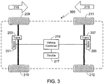
- motor 201 only provided forward torque and motor 205 only provided reverse torque. It should be understood that the same benefits are achieved if motor 201 is only used to generate reverse torque (i.e., causing vehicle travel in direction 215) and motor 205 is only used to generate forward torque (i.e., causing vehicle travel in direction 213). Vehicle 300 shown in Fig. 3 illustrates this configuration.
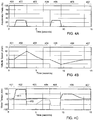
- Figs. 4A-C illustrate the invention using a fictitious drive cycle.
- the drive cycle in this example is divided into seven time periods, specifically (i) vehicle stopped (region 401); (ii) vehicle accelerating in a forward direction (region 402); (iii) vehicle decelerating using regenerative braking (region 403); (iv) vehicle stopped (region 404); (v) vehicle accelerating in a rearward direction (region 405); (vi) vehicle decelerating using regenerative braking (region 406); and (vii) vehicle stopped (region 407).
- FIG. 4A graphically illustrates depression of the accelerator pedal, where the accelerator pedal has a range of motion between fully depressed (i.e., 100% depressed) and fully released (i.e., 0% depressed).
- Fig. 4B graphically illustrates vehicle speed, where forward vehicle motion is shown as a positive value and rearward vehicle motion is shown as a negative value.
- Fig. 4C graphically illustrates motor torque, where forward torque is shown as a positive value (solid line 411) and reverse torque is shown as a negative value (dashed line 413). Due to the use of the invention, forward torque remains positive and reverse torque remains negative, thereby eliminating the backlash caused when a motor changes sign (i.e., going from forward torque to reverse torque or reverse to forward torque).
- the forward torque in this fictitious drive cycle is generated by motor 201 and the reverse torque is generated by motor 205.
- the forward torque in this fictitious drive cycle is generated by motor 205 and the reverse torque is generated by motor 201.
- the car is continually accelerating, i.e., the car never reaches a steady state speed.
- the car is continually accelerating in a rearward direction, i.e., the car never reaches a steady state speed.
- FIG. 5 While the illustrations of the invention provided above utilize two motors, i.e., one motor providing forward torque and one motor providing reverse torque, as previously noted the invention is equally applicable to EVs utilizing more than two motors.
- two motors 501 and 502 provide torque (e.g., forward torque) to wheels 503 and 504 in order to propel vehicle 500 in a direction 505.
- a single motor 507 provides torque (e.g., reverse torque) to wheels 509 and 510 in order to propel vehicle 500 in a direction 511.
- vehicle 600 Fig.
- the vehicle's system controller monitors the torque demand (T d ) requested by the driver. Torque demand is requested by the driver by pressing down, or otherwise engaging, the accelerator (also referred to as the throttle).
- the motor(s) generating torque in the requested direction i.e., either forward torque or reverse torque
- the motor(s) generating torque in the opposite direction i.e., either reverse torque or forward torque
- the motor(s) used to generate torque in the opposite direction provides additional torque in the requested direction. For example, assuming a two motor configuration as illustrated in Fig.
- system controller 219 can be configured to compare T d to a preset value rather than T P-max .
- system controller 210 can be configured to compare T d to a torque value that is 90% of T P-max , thereby avoiding placing the powertrain under unnecessary stress.
- Figs. 7A-7C illustrate the modified system using a fictitious drive cycle.
- the drive cycle in this example is divided into eight time periods, specifically (i) vehicle stopped (region 701); (ii) vehicle gradually accelerating in a forward direction (region 702); (iii) vehicle maintaining a constant speed (region 703); (iv) vehicle decelerating using regenerative braking (region 704); (v) vehicle stopped (region 705); (vi) vehicle rapidly accelerating in a forward direction (region 706); (vii) vehicle decelerating using regenerative braking (region 707); and (viii) vehicle stopped (region 708).
- Fig. 7A graphically illustrates depression of the accelerator pedal.
- Fig. 7B graphically illustrates vehicle speed.
- Fig. 7A graphically illustrates depression of the accelerator pedal.
- Fig. 7B graphically illustrates vehicle speed.
- Fig. 7A graphically illustrates depression of the accelerator pedal.
- Fig. 7B graphically illustrates vehicle speed.
- FIG. 7C graphically illustrates motor torque, where torque provided by the motor(s) primarily used for forward torque is shown as a solid line 711 and torque provided by the motor(s) primarily used for reverse torque is shown as a dashed line 713.
- line 713 briefly switches from a negative value (reverse torque) to a positive value (forward torque).
- both the forward torque powertrain(s) and the reverse torque powertrain(s) are supplying forward torque to the vehicle.
- T d the demand for forward torque
- T P-max maximum torque
- the vehicle's system controller monitors vehicle speed.
- the vehicle maintains forward torque on the powertrain(s) providing forward motion, and reverse torque on the powertrain(s) providing rearward motion, thereby eliminating powertrain backlash.
- the system operates as described initially and illustrated in Figs. 4A-4C .
- vehicle controller 219 reverts to conventional powertrain operation where all of the EV's powertrains (i.e., forward torque powertrain(s) and reverse torque powertrain(s)) operate in unison to generate torque in the same direction.
- Figs. 8A and 8B illustrate the speed sensitive modified system using a fictitious drive cycle. In this illustration it is assumed that the preset speed is set at approximately 30 mph.
- Fig. 8A graphically illustrates vehicle speed while Fig. 8B graphically illustrates motor torque, where torque provided by the powertrain(s) primarily used for forward torque is shown as a solid line 817 and torque provided by the powertrain(s) primarily used for reverse torque is shown as a dashed line 819.
- the drive cycle in this example is divided into fifteen time periods, specifically (i) vehicle stopped (region 801); (ii) vehicle gradually accelerating in a forward direction (region 802); (iii) vehicle maintaining a constant speed of approximately 15 mph (region 803); (iv) vehicle decelerating using regenerative braking (region 804); (v) vehicle stopped (region 805); (vi) vehicle gradually accelerating in a rearward direction (region 806); (vii) vehicle maintaining a constant speed in a rearward direction of approximately 10 mph (region 807); (viii) vehicle decelerating using regenerative braking (region 808); (ix) vehicle stopped (region 809); (x) vehicle gradually accelerating to approximately 70 mph (region 810); (xi) vehicle maintaining a constant speed of approximately 70 mph (region 811); (xii) vehicle decelerating to approximately 15 mph (region 812); (xiii) vehicle maintaining a constant speed in a forward direction of approximately 15 mph (region 813); (xiv
- forward torque is initially only provided by the forward powertrain(s). After the speed surpasses the preset speed (e.g., 30 mph), forward torque is also provided by the reverse powertrain(s). Both the forward and reverse torque powertrains provide forward torque during time period 811 when the car is cruising at 70 mph. As the vehicle decelerates to 15 mph during deceleration period 812, the reverse torque powertrain(s) provides regenerative braking. Then when the vehicle is traveling at a constant 15 mph (region 813), only the forward torque powertrain(s) provides torque.
- the preset speed e.g. 30 mph
Landscapes
- Engineering & Computer Science (AREA)
- Mechanical Engineering (AREA)
- Transportation (AREA)
- Chemical & Material Sciences (AREA)
- Combustion & Propulsion (AREA)
- General Engineering & Computer Science (AREA)
- Automation & Control Theory (AREA)
- Power Engineering (AREA)
- Physics & Mathematics (AREA)
- Mathematical Physics (AREA)
- Electric Propulsion And Braking For Vehicles (AREA)
- Hybrid Electric Vehicles (AREA)
- Arrangement Or Mounting Of Propulsion Units For Vehicles (AREA)
Description
- The present invention relates generally to an electric vehicle and, more particularly, to a control system configured to eliminate the mechanical backlash in an electric vehicle's powertrain.
- The components within a vehicle's powertrain transfer the output generated by the vehicle's motor or engine to the vehicle's wheels. Many of these components, for example the transmission, drive shaft and differential, utilize an arrangement of gears to accomplish this power transfer. Due to the limitations of the manufacturing process, as well as the need for a degree of clearance to permit operation at various temperatures, there is a certain level of play between gears, commonly referred to as backlash.
Fig. 1 illustratesbacklash 101 between twogears - The primary concern with backlash in a vehicle's powertrain is the vibration and noise that results when the backlash within the various gear linkages is traversed, for example when a car shifts between acceleration and braking or vice versa. Each time the backlash is traversed, the vehicle's driver and passengers feel the car shutter or jerk, a feeling that is often accompanied by the noise of the gear teeth impacting against one another.
- Car designers utilize a variety of techniques to overcome this issue, thereby providing a smoother, less jarring ride to their vehicle's passengers. In general, these techniques utilize a type of mechanical filter interposed between individual members of the powertrain. For example, a flexible rubber coupling may be interposed between a vehicle's driveshaft and the differential, the rubber coupling absorbing much of the vibration caused by powertrain backlash. In addition to mechanical filtering, car designers also utilize various engine control systems to perform this same function, where the control systems estimate the backlash and then use a feedback system to minimize its effects. Unfortunately while filtering techniques do lessen the effects of powertrain backlash, they also lessen powertrain responsiveness. Accordingly, what is needed is a system that minimizes, if not all together eliminates, the effects of powertrain backlash without reducing vehicle responsiveness. The present invention provides such a control system.
- The
US 2018/0312081 A1 discloses a controller for a motor vehicle powertrain, the controller being configured to control the amount of torque generated by each of a plurality of drive torque sources. By maintaining the direction of application of torque in the same direction relative to a body of the vehicle, lash crossing associated with transfer of torque from each of the plurality of drive torque sources to the respective group of one or more wheels may be substantially prevented. When the amount of driver demanded torque in the forward direction of driving approaches a threshold value from a value below the threshold value, a transition from a negative torque application condition to a positive torque application condition is controlled so that, as the amount of torque passes through zero, the rate of change of the amount of torque developed by the first electric machine is reduced to a value not exceeding a predetermined torque rate limit value. The controller causes the amount of torque generated by the second electric machine to stop increasing and begins to reduce the amount of negative torque generated by the first electric machine at a rate that is determined by the amount of torque demanded by the driver. -
JP2018057169A - The present invention provides a powertrain backlash control system as claimed in
claim 1. During in-gear EV operation, when the EV is stopped the minimum forward torque demand is offset by the minimum reverse torque demand, thereby preventing EV movement in either a forward or rearward direction. - After receiving the torque request, the vehicle controller transmits a corresponding torque demand to at least one of the first and second powertrains, where the corresponding torque demand is selected from the plurality of forward torque demands and the plurality of reverse torque demands.
- In another aspect, when the torque request corresponds to a forward torque request the vehicle controller may be configured to compare the torque request to a preset value. If the torque request exceeds the preset value, the vehicle controller may be configured to temporarily cease transmitting reverse torque demands to the second powertrain and to transmit a forward torque demand to the second powertrain. Similarly, when the torque request corresponds to a rearward torque request the vehicle controller may be configured to compare the torque request to a second preset value. If the torque request exceeds the second preset value, the vehicle controller may be configured to temporarily cease transmitting forward torque demands to the first powertrain and to transmit a reverse torque demand to the first powertrain. The preset value may correspond to the maximum torque available from the first powertrain. The second preset value may correspond to the maximum torque available from the second powertrain.
- A further understanding of the nature and advantages of the present invention may be realized by reference to the remaining portions of the specification and the drawings.
- It should be understood that the accompanying figures are only meant to illustrate, not limit, the scope of the invention and should not be considered to be to scale. Additionally, the same reference label on different figures should be understood to refer to the same component or a component of similar functionality.
-
Fig. 1 illustrates backlash between two gears, where only a portion of each of the gears is shown; -
Fig. 2 illustrates a preferred embodiment of the invention in an EV with two motors; -
Fig. 3 illustrates an embodiment similar to that shown inFig. 2 , except for the direction of torque applied by each of the vehicle's motors. -
Figs. 4A-C illustrate the invention using a fictitious drive cycle, withFig. 4A graphically illustrating accelerator pedal depression,Fig. 4B graphically illustrating vehicle speed, andFig. 4C graphically illustrating motor torque; -
Fig. 5 illustrates an embodiment similar to those shown inFigs. 2 and3 , except that three motors are used rather than two; -
Fig. 6 illustrates an embodiment similar to those shown inFigs. 2 and3 , except that four motors are used rather than two; -
Figs. 7A-C illustrate a system modification using a fictitious drive cycle, withFig. 7A graphically illustrating accelerator pedal depression,Fig. 7B graphically illustrating vehicle speed, andFig. 7C graphically illustrating motor torque; and -
Figs. 8A-B illustrate a system modification using a fictitious drive cycle, withFig. 8A graphically illustrating vehicle speed andFig. 8B graphically illustrating motor torque. - As used herein, the singular forms "a", "an" and "the" are intended to include the plural forms as well, unless the context clearly indicates otherwise. The terms "comprises", "comprising", "includes", and/or "including", as used herein, specify the presence of stated features, integers, steps, operations, elements, and/or components, but do not preclude the presence or addition of one or more other features, integers, steps, operations, elements, components, and/or groups thereof. As used herein, the term "and/or" and the symbol "/" are meant to include any and all combinations of one or more of the associated listed items. Additionally, while the terms first, second, etc. may be used herein to describe various steps or calculations, these steps or calculations should not be limited by these terms, rather these terms are only used to distinguish one step or calculation from another. For example, a first calculation could be termed a second calculation; similarly a first step could be termed a second step; similarly a first component could be termed a second component, all without departing from the scope of this disclosure. The term "battery pack" as used herein refers to one or more batteries electrically interconnected to achieve the desired voltage and capacity. The terms "electric vehicle" and "EV" may be used interchangeably and may refer to an all-electric vehicle, a plug-in hybrid vehicle, also referred to as a PHEV, or a hybrid vehicle, also referred to as a HEV, where a hybrid vehicle utilizes multiple sources of propulsion including an electric drive system. As used herein, "forward torque" refers to torque applied in a forward direction of travel and "reverse torque" refers to torque applied in a rearward direction of travel. Accordingly, if a car is traveling in a forward direction, forward torque refers to motor torque that promotes and sustains forward motion of the car while reverse torque refers to motor torque that is applied in the opposite direction in order to cause the car to decelerate or travel in a reverse direction. Additionally, in an EV reverse torque may be applied via regenerative braking in order to slow the vehicle's forward travel and forward torque may be applied via regenerative braking in order to slow the vehicle's rearward travel. In accordance with the invention, powertrain backlash is eliminated by maintaining motor torque within a particular powertrain in the same direction at all times. When applied to a vehicle where it is necessary to provide means of travel in both forward and rearward directions, it will be appreciated that the invention is limited to EV's that include at least two powertrains, one for propelling the vehicle in the forward direction and one for propelling the vehicle in the rearward direction.
-
Fig. 2 schematically illustrates an implementation of the preferred embodiment. As shown,EV 200 includes afirst motor 201 andtransmission 203 and asecond motor 205 andtransmission 207.Motor 201/transmission 203 provides torque towheels motor 205/transmission 207 provides torque towheels - To eliminate the previously described problem of powertrain backlash,
motor 201 andtransmission 203 only provide forward torque, thereby propellingvehicle 200 in adirection 213. Similarly,motor 205 andtransmission 207 only provide reverse torque, thereby propellingvehicle 200 in adirection 215. To prevent backlash,motor 201 always provides forward torque whilemotor 205 always provides reverse torque. The amount of torque applied by either motor depends upon the driver's desired direction of travel. For example, if the driver is accelerating in a forward direction, i.e.,direction 213, then a large forward torque is generated bymotor 201. At the same time, a small reverse torque is generated bymotor 205. The amount of reverse torque generated bymotor 205 is sufficient to ensure that there is no backlash in that powertrain when the driver wishes to decelerate or reverse direction, but small enough to have a relatively insignificant impact on forward vehicle travel and overall vehicle efficiency. When the driver decides to decelerate, assuming that the vehicle utilizes regenerative braking in addition to, or in lieu of, friction braking, then the forward torque generated bymotor 201 is reduced and the reverse torque generated bymotor 205 is increased. Similarly if the driver wishes to travel in a rearward direction, i.e.,direction 215, then a large reverse torque is generated bymotor 205 while simultaneously a small forward torque is generated bymotor 201. As in the previous example, the amount of forward torque generated bymotor 201 is sufficient to ensure that there is no backlash in that powertrain while being small enough to have a relatively insignificant impact on rearward vehicle travel and overall vehicle efficiency. Note that when the vehicle is stationary and in gear (i.e., as opposed to being parked), a small amount of forward torque is generated bymotor 201 and a small amount of reverse torque is generated bymotor 205, the amount of forward torque being sufficient to counter the reverse torque generated bymotor 205 without being large enough to cause forward vehicle travel. Similarly, the amount of reverse torque is sufficient to counter the forward torque generated bymotor 201 without being large enough to cause rearward vehicle travel. - In the previous example,
motor 201 only provided forward torque andmotor 205 only provided reverse torque. It should be understood that the same benefits are achieved ifmotor 201 is only used to generate reverse torque (i.e., causing vehicle travel in direction 215) andmotor 205 is only used to generate forward torque (i.e., causing vehicle travel in direction 213).Vehicle 300 shown inFig. 3 illustrates this configuration. -
Figs. 4A-C illustrate the invention using a fictitious drive cycle. The drive cycle in this example is divided into seven time periods, specifically (i) vehicle stopped (region 401); (ii) vehicle accelerating in a forward direction (region 402); (iii) vehicle decelerating using regenerative braking (region 403); (iv) vehicle stopped (region 404); (v) vehicle accelerating in a rearward direction (region 405); (vi) vehicle decelerating using regenerative braking (region 406); and (vii) vehicle stopped (region 407).Fig. 4A graphically illustrates depression of the accelerator pedal, where the accelerator pedal has a range of motion between fully depressed (i.e., 100% depressed) and fully released (i.e., 0% depressed).Fig. 4B graphically illustrates vehicle speed, where forward vehicle motion is shown as a positive value and rearward vehicle motion is shown as a negative value.Fig. 4C graphically illustrates motor torque, where forward torque is shown as a positive value (solid line 411) and reverse torque is shown as a negative value (dashed line 413). Due to the use of the invention, forward torque remains positive and reverse torque remains negative, thereby eliminating the backlash caused when a motor changes sign (i.e., going from forward torque to reverse torque or reverse to forward torque). - Assuming the use of the embodiment illustrated in
Fig. 2 , the forward torque in this fictitious drive cycle is generated bymotor 201 and the reverse torque is generated bymotor 205. Assuming the use of the embodiment illustrated inFig. 3 , the forward torque in this fictitious drive cycle is generated bymotor 205 and the reverse torque is generated bymotor 201. Note that in the example provided inFigs. 4A-C , during the second time period (region 402) the car is continually accelerating, i.e., the car never reaches a steady state speed. Similarly, during the fifth time period (region 405) the car is continually accelerating in a rearward direction, i.e., the car never reaches a steady state speed. - While the illustrations of the invention provided above utilize two motors, i.e., one motor providing forward torque and one motor providing reverse torque, as previously noted the invention is equally applicable to EVs utilizing more than two motors. For example, in the embodiment illustrated in
Fig. 5 , twomotors wheels vehicle 500 in adirection 505. In this embodiment, asingle motor 507 provides torque (e.g., reverse torque) towheels vehicle 500 in adirection 511. In yet another example, vehicle 600 (Fig. 6 ) utilizes twomotors wheels vehicle 600 in adirection 605, and twomotors wheels vehicle 600 in adirection 611. - The approach described above eliminates powertrain backlash, and therefore eliminates the jerkiness and noise that typically accompanies powertrain backlash. However, as each motor continually applies torque in opposition to the torque generated by another of the vehicle's motors, vehicle powertrain efficiency is degraded. Although the degree of degradation is minimal given that only a small amount of torque must be generated in order to eliminate powertrain backlash, it will be appreciated that even a small amount of degradation may be undesirable in some scenarios. In addition to the loss of efficiency due to at least one motor generating torque in opposition to the torque generated by at least one other motor, the approach described above does not take full advantage of the EV's combined motor capabilities. Clearly in a two motor EV, additional acceleration and top speed can be achieved when both motors are operating in unison, rather than counter to one another. To overcome these limitations, the inventor envisions several modifications to the above system. In one modification of the above described system, the vehicle's system controller monitors the torque demand (Td) requested by the driver. Torque demand is requested by the driver by pressing down, or otherwise engaging, the accelerator (also referred to as the throttle). Under normal conditions and as described above, as the driver increases their torque demand the motor(s) generating torque in the requested direction (i.e., either forward torque or reverse torque) increases the generated torque while the motor(s) generating torque in the opposite direction (i.e., either reverse torque or forward torque) generates minimal torque, thereby eliminating powertrain backlash. However in this modified approach, when the driver requests torque in excess of that which can be generated by the motor(s) generating torque in the requested direction, the motor(s) used to generate torque in the opposite direction provides additional torque in the requested direction. For example, assuming a two motor configuration as illustrated in
Fig. 2 , if the driver requests forward motion (i.e., by placing the car in a forward gear) and presses down on the accelerator (or otherwise activates throttle 217) to such a degree that the torque demand (Td) cannot be met by the maximum torque (TP-max) generated bymotor 201, then in the modified system thevehicle controller 219 would utilizemotor 205 to generate additional forward torque. In other words, if Td is greater than TP-max, then the vehicle controller utilizes bothmotors - It should be understood that in the above-modified system,
system controller 219 can be configured to compare Td to a preset value rather than TP-max. For example,system controller 210 can be configured to compare Td to a torque value that is 90% of TP-max, thereby avoiding placing the powertrain under unnecessary stress. -
Figs. 7A-7C illustrate the modified system using a fictitious drive cycle. The drive cycle in this example is divided into eight time periods, specifically (i) vehicle stopped (region 701); (ii) vehicle gradually accelerating in a forward direction (region 702); (iii) vehicle maintaining a constant speed (region 703); (iv) vehicle decelerating using regenerative braking (region 704); (v) vehicle stopped (region 705); (vi) vehicle rapidly accelerating in a forward direction (region 706); (vii) vehicle decelerating using regenerative braking (region 707); and (viii) vehicle stopped (region 708).Fig. 7A graphically illustrates depression of the accelerator pedal.Fig. 7B graphically illustrates vehicle speed.Fig. 7C graphically illustrates motor torque, where torque provided by the motor(s) primarily used for forward torque is shown as asolid line 711 and torque provided by the motor(s) primarily used for reverse torque is shown as a dashedline 713. Note that duringperiod 706 when the driver is demanding rapid acceleration by pressing the accelerator pedal to the floor (e.g., 100% pedal depression),line 713 briefly switches from a negative value (reverse torque) to a positive value (forward torque). As such, for a brief period of time both the forward torque powertrain(s) and the reverse torque powertrain(s) are supplying forward torque to the vehicle. Once the demand for forward torque (Td) drops below the maximum torque (TP-max) available from the forward torque powertrain(s), or below a preset torque value, the reverse torque powertrain(s) switches back to a negative torque value as shown. - In another modification of the system of the invention, the vehicle's system controller monitors vehicle speed. During low speed operation, the vehicle maintains forward torque on the powertrain(s) providing forward motion, and reverse torque on the powertrain(s) providing rearward motion, thereby eliminating powertrain backlash. As such, during low speed operation of the vehicle when powertrain backlash is most noticeable, the system operates as described initially and illustrated in
Figs. 4A-4C . Once a preset speed is reached, for example 30 mph,vehicle controller 219 reverts to conventional powertrain operation where all of the EV's powertrains (i.e., forward torque powertrain(s) and reverse torque powertrain(s)) operate in unison to generate torque in the same direction. Operation in this manner continues until vehicle speed drops below the preset speed, at which time the system reverts to the system of the invention whereby backlash is eliminated by maintaining forward torque on the powertrain(s) providing forward torque and maintaining rearward torque on the powertrain(s) providing reverse torque. -
Figs. 8A and 8B illustrate the speed sensitive modified system using a fictitious drive cycle. In this illustration it is assumed that the preset speed is set at approximately 30 mph.Fig. 8A graphically illustrates vehicle speed whileFig. 8B graphically illustrates motor torque, where torque provided by the powertrain(s) primarily used for forward torque is shown as asolid line 817 and torque provided by the powertrain(s) primarily used for reverse torque is shown as a dashedline 819. The drive cycle in this example is divided into fifteen time periods, specifically (i) vehicle stopped (region 801); (ii) vehicle gradually accelerating in a forward direction (region 802); (iii) vehicle maintaining a constant speed of approximately 15 mph (region 803); (iv) vehicle decelerating using regenerative braking (region 804); (v) vehicle stopped (region 805); (vi) vehicle gradually accelerating in a rearward direction (region 806); (vii) vehicle maintaining a constant speed in a rearward direction of approximately 10 mph (region 807); (viii) vehicle decelerating using regenerative braking (region 808); (ix) vehicle stopped (region 809); (x) vehicle gradually accelerating to approximately 70 mph (region 810); (xi) vehicle maintaining a constant speed of approximately 70 mph (region 811); (xii) vehicle decelerating to approximately 15 mph (region 812); (xiii) vehicle maintaining a constant speed in a forward direction of approximately 15 mph (region 813); (xiv) vehicle decelerating using regenerative braking (region 814); and (xv) vehicle stopped (region 815). - Note that during
time period 810 as the vehicle gradually accelerates from 0 mph to 70 mph, forward torque is initially only provided by the forward powertrain(s). After the speed surpasses the preset speed (e.g., 30 mph), forward torque is also provided by the reverse powertrain(s). Both the forward and reverse torque powertrains provide forward torque duringtime period 811 when the car is cruising at 70 mph. As the vehicle decelerates to 15 mph duringdeceleration period 812, the reverse torque powertrain(s) provides regenerative braking. Then when the vehicle is traveling at a constant 15 mph (region 813), only the forward torque powertrain(s) provides torque. - It should be understood that while separate examples are provided herein for modified systems in which (i) torque demand is used to determine when the EV's forward and reverse torque powertrains operate in unison and (ii) vehicle speed is used to determine when the EV's forward and reverse torque powertrains operate in unison, the inventor clearly envisions a system in which both of these modifications are combined into a single system. In such a system under normal operation, i.e., when the torque demand, Td, does not exceed a preset torque value (e.g., TP-max) and the vehicle speed does not exceed a preset value (e.g., 30 mph), forward torque is maintained in the forward torque powertrain(s) and reverse torque is maintained in the reverse torque powertrain(s) in order to eliminate powertrain backlash. Whenever the torque demand exceeds the preset torque value or the vehicle speed exceeds the preset value, both the forward and reverse torque powertrains operate together to generate torque in the desired direction.
- As specific powertrain torque values depend on the specifics of the powertrain in question (e.g., motor characteristics, etc.), it should be understood that the torque values provided in the exemplary drive cycles shown in
Figs. 4A-C ,7A-C , and8A/8B are only intended to illustrate, not limit, the invention.
Claims (11)
- A powertrain backlash control system, comprising:a first powertrain, said first powertrain configured to propel an electric vehicle, EV, (200) in a forward direction (213) and in a rearward direction (215), said first powertrain comprising a first motor (201);a second powertrain, said second powertrain configured to propel said EV (200) in a forward direction (213) and in a rearward direction (215), said second powertrain comprising a second motor (205);a vehicle controller (219) coupled to said first powertrain and to said second powertrain, said vehicle controller (219) configured to transmit a plurality of forward torque demands to said first powertrain and configured to transmit a plurality of reverse torque demands to said second powertrain, wherein during in-gear EV operation said vehicle controller (219) maintains at least a minimum forward torque demand on said first powertrain and maintains at least a minimum reverse torque demand on said second powertrain, wherein said minimum forward torque demand is greater than zero, and wherein said minimum reverse torque demand is greater than zero; andan accelerator assembly (217) coupled to said vehicle controller (219), said accelerator assembly (217) configured to receive a torque request from a driver of said EV (200) and transmit said torque request to said vehicle controller (219), said torque request selected from within a range of possible torque requests, said range of possible torque requests comprising a range of forward torque requests and a range of reverse torque requests,characterized in thatsaid vehicle controller (219) is configured to compare a current vehicle speed to a preset value when said torque request corresponds to a forward torque request selected from said range of forward torque requests and to temporarily cease transmitting reverse torque demands to said second powertrain and to transmit a forward torque demand to said second powertrain when said current vehicle speed exceeds said preset value; orsaid vehicle controller (219) is configured to compare said current vehicle speed to a second preset value when said torque request corresponds to a reverse torque request selected from said range of reverse torque requests and to temporarily cease transmitting forward torque demands to said first powertrain and to transmit a reverse torque demand to said first powertrain when said current vehicle speed exceeds said second preset value.
- The powertrain backlash control system of claim 1, wherein during in-gear EV operation when said EV (200) is stopped said minimum forward torque demand is offset by said minimum reverse torque demand to prevent EV movement in said forward direction (213) and to prevent EV movement in said rearward direction (215).
- The powertrain backlash control system of claim 1, said first powertrain further comprising a third motor (502).
- The powertrain backlash control system of claim 1, said second powertrain further comprising a fourth motor (608).
- The powertrain backlash control system of claim 1, wherein said vehicle controller (219) transmits a corresponding torque demand to at least one of said first powertrain and said second powertrain when said vehicle controller (219) receives said torque request from said accelerator assembly (217), wherein said corresponding torque demand is selected from said plurality of forward torque demands and said plurality of reverse torque demands.
- The powertrain backlash control system of claim 1, said vehicle controller (219) configured to compare said torque request to a preset value when said torque request corresponds to a forward torque request selected from said range of forward torque requests.
- The powertrain backlash control system of claim 6, said vehicle controller (219) configured to temporarily cease transmitting reverse torque demands to said second powertrain and to transmit a forward torque demand to said second powertrain when said torque request exceeds said preset value.
- The powertrain backlash control system of claim 6, said preset value corresponding to a maximum torque available from said first powertrain.
- The powertrain backlash control system of claim 6, said vehicle controller (219) configured to compare said torque request to a second preset value when said torque request corresponds to a reverse torque request selected from said range of reverse torque requests.
- The powertrain backlash control system of claim 9, said vehicle controller (219) configured to temporarily cease transmitting forward torque demands to said first powertrain and to transmit a reverse torque demand to said first powertrain when said torque request exceeds said second preset value.
- The powertrain backlash control system of claim 9, said second preset value corresponding to a maximum torque available from said second powertrain.
Applications Claiming Priority (1)
| Application Number | Priority Date | Filing Date | Title |
|---|---|---|---|
| US16/250,122 US11413972B2 (en) | 2019-01-17 | 2019-01-17 | Control system to eliminate power train backlash |
Publications (2)
| Publication Number | Publication Date |
|---|---|
| EP3683078A1 EP3683078A1 (en) | 2020-07-22 |
| EP3683078B1 true EP3683078B1 (en) | 2021-07-07 |
Family
ID=69157747
Family Applications (1)
| Application Number | Title | Priority Date | Filing Date |
|---|---|---|---|
| EP20151208.4A Active EP3683078B1 (en) | 2019-01-17 | 2020-01-10 | Control system to eliminate powertrain backlash |
Country Status (5)
| Country | Link |
|---|---|
| US (1) | US11413972B2 (en) |
| EP (1) | EP3683078B1 (en) |
| JP (1) | JP6977227B2 (en) |
| KR (1) | KR20200089601A (en) |
| CN (2) | CN111439265B (en) |
Families Citing this family (12)
| Publication number | Priority date | Publication date | Assignee | Title |
|---|---|---|---|---|
| US11413972B2 (en) * | 2019-01-17 | 2022-08-16 | Atieva, Inc. | Control system to eliminate power train backlash |
| CN111993904A (en) * | 2020-09-09 | 2020-11-27 | 北京罗克维尔斯科技有限公司 | Drive control method and device and electric vehicle |
| CN113071330B (en) * | 2021-04-16 | 2022-12-02 | 中国第一汽车股份有限公司 | Motor torque control method, system, vehicle and storage medium |
| CN115195646B (en) * | 2022-07-18 | 2025-06-10 | 岚图汽车科技有限公司 | Vehicle gear noise adjusting method and related equipment |
| KR20240142685A (en) * | 2023-03-22 | 2024-10-02 | 현대자동차주식회사 | Torque control method for drive system of electric vehicle |
| KR20240142684A (en) * | 2023-03-22 | 2024-10-02 | 현대자동차주식회사 | Torque control method for drive system of electric vehicle |
| GB2629823A (en) * | 2023-05-11 | 2024-11-13 | Jaguar Land Rover Ltd | A control system for a vehicle powertrain |
| KR20250001549A (en) * | 2023-06-29 | 2025-01-07 | 현대자동차주식회사 | Torque control method for drive system of electric vehicle |
| KR20250011270A (en) * | 2023-07-14 | 2025-01-21 | 현대자동차주식회사 | Torque control method for drive system of electric vehicle |
| SE2351136A1 (en) * | 2023-10-03 | 2025-04-04 | Scania Cv Ab | Method for reducing backlash in a vehicle and control arrangent configured to perform the method |
| EP4644163A1 (en) * | 2024-05-03 | 2025-11-05 | Volvo Truck Corporation | Control system and method for avoiding torque loss during changing moving direction of electrical vehicle |
| US20260103088A1 (en) * | 2024-10-11 | 2026-04-16 | Hyundai Motor Company | Torque control system and method for drive system of electric vehicle |
Family Cites Families (16)
| Publication number | Priority date | Publication date | Assignee | Title |
|---|---|---|---|---|
| JP3175895B2 (en) | 1993-04-28 | 2001-06-11 | 株式会社日立製作所 | Electric vehicle drive system |
| US6603215B2 (en) * | 2001-05-24 | 2003-08-05 | Ford Global Technologies, Llc | Hybrid electric vehicle control strategy while traveling in reverse |
| US6805647B2 (en) * | 2002-09-27 | 2004-10-19 | Ford Motor Company | Hybrid electric vehicle auxiliary oil pump |
| JP4807030B2 (en) | 2005-10-11 | 2011-11-02 | トヨタ自動車株式会社 | Braking / driving control device |
| US7971667B2 (en) * | 2007-04-19 | 2011-07-05 | Ford Global Technologies, Llc | System and method of inhibiting the effects of driveline backlash in a hybrid propulsion system |
| US20090237026A1 (en) * | 2008-03-18 | 2009-09-24 | Siemens Energy & Automation, Inc. | System and Method for Drive Controller Anti-Backlash Control Topology |
| JP6127898B2 (en) | 2013-10-15 | 2017-05-17 | トヨタ自動車株式会社 | Braking / driving force control device for vehicle |
| US9340199B1 (en) * | 2014-12-10 | 2016-05-17 | Ford Global Technologies, Llc | Method of braking in hybrid vehicle |
| JP6585473B2 (en) | 2015-11-09 | 2019-10-02 | 株式会社Subaru | Automatic parking control device |
| GB2544764B (en) | 2015-11-25 | 2019-04-03 | Jaguar Land Rover Ltd | Controller for a motor vehicle and method |
| GB2544763B (en) | 2015-11-25 | 2019-03-27 | Jaguar Land Rover Ltd | Controller for a motor vehicle and method |
| US10994721B2 (en) * | 2016-09-13 | 2021-05-04 | Ford Global Technologies, Llc | Engine and motor control during wheel torque reversal in a hybrid vehicle |
| JP6823415B2 (en) | 2016-09-29 | 2021-02-03 | 株式会社Subaru | Vehicle control device and vehicle control method |
| DE102017210075A1 (en) | 2017-06-14 | 2018-12-20 | Bayerische Motoren Werke Aktiengesellschaft | A method of driving a vehicle driveline |
| US10857993B2 (en) * | 2018-09-10 | 2020-12-08 | Ford Global Technologies, Llc | Methods and system activating a vehicle |
| US11413972B2 (en) * | 2019-01-17 | 2022-08-16 | Atieva, Inc. | Control system to eliminate power train backlash |
-
2019
- 2019-01-17 US US16/250,122 patent/US11413972B2/en active Active
- 2019-12-13 JP JP2019225337A patent/JP6977227B2/en active Active
- 2019-12-27 KR KR1020190176022A patent/KR20200089601A/en not_active Ceased
-
2020
- 2020-01-09 CN CN202010021068.3A patent/CN111439265B/en not_active Expired - Fee Related
- 2020-01-09 CN CN202020045847.2U patent/CN212605077U/en not_active Withdrawn - After Issue
- 2020-01-10 EP EP20151208.4A patent/EP3683078B1/en active Active
Also Published As
| Publication number | Publication date |
|---|---|
| JP6977227B2 (en) | 2021-12-08 |
| US11413972B2 (en) | 2022-08-16 |
| CN111439265A (en) | 2020-07-24 |
| EP3683078A1 (en) | 2020-07-22 |
| JP2020115737A (en) | 2020-07-30 |
| KR20200089601A (en) | 2020-07-27 |
| US20200231048A1 (en) | 2020-07-23 |
| CN111439265B (en) | 2023-08-29 |
| CN212605077U (en) | 2021-02-26 |
Similar Documents
| Publication | Publication Date | Title |
|---|---|---|
| EP3683078B1 (en) | Control system to eliminate powertrain backlash | |
| US11254220B2 (en) | Controller for a motor vehicle and method | |
| US10576838B2 (en) | Controller for a motor vehicle and method | |
| CN103043056B (en) | Control vehicle wheel axle torque method and for its control system | |
| US8160763B2 (en) | Method and apparatus for controlling creep torque in a vehicle equipped with a hybrid powertrain system | |
| US11619272B2 (en) | Dog clutch engagement method of electric four-wheel drive vehicle | |
| US8897982B2 (en) | Method for driving a hybrid vehicle in a load reversal | |
| JP7035781B2 (en) | Vehicle shift control device | |
| CN107150688B (en) | Hybrid vehicle and lash mitigation strategy | |
| US20250010855A1 (en) | Method for operating a motor vehicle, control unit, motor vehicle | |
| EP3858693A1 (en) | Electric-powered vehicle control method and electric-powered vehicle drive system | |
| CN110386001A (en) | Transverse movement control for turning and regenerating braking energy captures | |
| CN112092612B (en) | Four-wheel drive pure electric vehicle power system | |
| US20250058644A1 (en) | Method of controlling torque of an electric vehicle driving system | |
| JP3552708B2 (en) | Power transmission device for hybrid vehicle | |
| EP3981632B1 (en) | Method and system for controlling a hybrid electric driveline | |
| GB2634064A (en) | Controlling a vehicle braking system | |
| EP4091859A1 (en) | Control device | |
| JP2026013484A (en) | Method and device for controlling driving force of four-wheel drive vehicle | |
| WO2023058639A1 (en) | Vehicle control device | |
| JP2025541457A (en) | Method for controlling an electrical assembly of a motor vehicle having an internal combustion engine using a hybridized manual gearbox |
Legal Events
| Date | Code | Title | Description |
|---|---|---|---|
| PUAI | Public reference made under article 153(3) epc to a published international application that has entered the european phase |
Free format text: ORIGINAL CODE: 0009012 |
|
| STAA | Information on the status of an ep patent application or granted ep patent |
Free format text: STATUS: REQUEST FOR EXAMINATION WAS MADE |
|
| 17P | Request for examination filed |
Effective date: 20200110 |
|
| AK | Designated contracting states |
Kind code of ref document: A1 Designated state(s): AL AT BE BG CH CY CZ DE DK EE ES FI FR GB GR HR HU IE IS IT LI LT LU LV MC MK MT NL NO PL PT RO RS SE SI SK SM TR |
|
| AX | Request for extension of the european patent |
Extension state: BA ME |
|
| RBV | Designated contracting states (corrected) |
Designated state(s): AL AT BE BG CH CY CZ DE DK EE ES FI FR GB GR HR HU IE IS IT LI LT LU LV MC MK MT NL NO PL PT RO RS SE SI SK SM TR |
|
| REG | Reference to a national code |
Ref country code: DE Ref legal event code: R079 Ref document number: 602020000208 Country of ref document: DE Free format text: PREVIOUS MAIN CLASS: B60K0001020000 Ipc: B60K0001000000 |
|
| RIC1 | Information provided on ipc code assigned before grant |
Ipc: B60K 1/00 20060101AFI20201217BHEP Ipc: B60K 17/04 20060101ALI20201217BHEP Ipc: B60K 7/00 20060101ALI20201217BHEP |
|
| GRAP | Despatch of communication of intention to grant a patent |
Free format text: ORIGINAL CODE: EPIDOSNIGR1 |
|
| STAA | Information on the status of an ep patent application or granted ep patent |
Free format text: STATUS: GRANT OF PATENT IS INTENDED |
|
| INTG | Intention to grant announced |
Effective date: 20210205 |
|
| GRAS | Grant fee paid |
Free format text: ORIGINAL CODE: EPIDOSNIGR3 |
|
| GRAA | (expected) grant |
Free format text: ORIGINAL CODE: 0009210 |
|
| STAA | Information on the status of an ep patent application or granted ep patent |
Free format text: STATUS: THE PATENT HAS BEEN GRANTED |
|
| AK | Designated contracting states |
Kind code of ref document: B1 Designated state(s): AL AT BE BG CH CY CZ DE DK EE ES FI FR GB GR HR HU IE IS IT LI LT LU LV MC MK MT NL NO PL PT RO RS SE SI SK SM TR |
|
| REG | Reference to a national code |
Ref country code: GB Ref legal event code: FG4D |
|
| REG | Reference to a national code |
Ref country code: AT Ref legal event code: REF Ref document number: 1408233 Country of ref document: AT Kind code of ref document: T Effective date: 20210715 |
|
| REG | Reference to a national code |
Ref country code: DE Ref legal event code: R096 Ref document number: 602020000208 Country of ref document: DE |
|
| REG | Reference to a national code |
Ref country code: IE Ref legal event code: FG4D |
|
| REG | Reference to a national code |
Ref country code: NL Ref legal event code: FP |
|
| REG | Reference to a national code |
Ref country code: LT Ref legal event code: MG9D |
|
| REG | Reference to a national code |
Ref country code: AT Ref legal event code: MK05 Ref document number: 1408233 Country of ref document: AT Kind code of ref document: T Effective date: 20210707 |
|
| PG25 | Lapsed in a contracting state [announced via postgrant information from national office to epo] |
Ref country code: ES Free format text: LAPSE BECAUSE OF FAILURE TO SUBMIT A TRANSLATION OF THE DESCRIPTION OR TO PAY THE FEE WITHIN THE PRESCRIBED TIME-LIMIT Effective date: 20210707 Ref country code: SE Free format text: LAPSE BECAUSE OF FAILURE TO SUBMIT A TRANSLATION OF THE DESCRIPTION OR TO PAY THE FEE WITHIN THE PRESCRIBED TIME-LIMIT Effective date: 20210707 Ref country code: RS Free format text: LAPSE BECAUSE OF FAILURE TO SUBMIT A TRANSLATION OF THE DESCRIPTION OR TO PAY THE FEE WITHIN THE PRESCRIBED TIME-LIMIT Effective date: 20210707 Ref country code: PT Free format text: LAPSE BECAUSE OF FAILURE TO SUBMIT A TRANSLATION OF THE DESCRIPTION OR TO PAY THE FEE WITHIN THE PRESCRIBED TIME-LIMIT Effective date: 20211108 Ref country code: NO Free format text: LAPSE BECAUSE OF FAILURE TO SUBMIT A TRANSLATION OF THE DESCRIPTION OR TO PAY THE FEE WITHIN THE PRESCRIBED TIME-LIMIT Effective date: 20211007 Ref country code: FI Free format text: LAPSE BECAUSE OF FAILURE TO SUBMIT A TRANSLATION OF THE DESCRIPTION OR TO PAY THE FEE WITHIN THE PRESCRIBED TIME-LIMIT Effective date: 20210707 Ref country code: HR Free format text: LAPSE BECAUSE OF FAILURE TO SUBMIT A TRANSLATION OF THE DESCRIPTION OR TO PAY THE FEE WITHIN THE PRESCRIBED TIME-LIMIT Effective date: 20210707 Ref country code: AT Free format text: LAPSE BECAUSE OF FAILURE TO SUBMIT A TRANSLATION OF THE DESCRIPTION OR TO PAY THE FEE WITHIN THE PRESCRIBED TIME-LIMIT Effective date: 20210707 Ref country code: BG Free format text: LAPSE BECAUSE OF FAILURE TO SUBMIT A TRANSLATION OF THE DESCRIPTION OR TO PAY THE FEE WITHIN THE PRESCRIBED TIME-LIMIT Effective date: 20211007 Ref country code: LT Free format text: LAPSE BECAUSE OF FAILURE TO SUBMIT A TRANSLATION OF THE DESCRIPTION OR TO PAY THE FEE WITHIN THE PRESCRIBED TIME-LIMIT Effective date: 20210707 |
|
| PG25 | Lapsed in a contracting state [announced via postgrant information from national office to epo] |
Ref country code: PL Free format text: LAPSE BECAUSE OF FAILURE TO SUBMIT A TRANSLATION OF THE DESCRIPTION OR TO PAY THE FEE WITHIN THE PRESCRIBED TIME-LIMIT Effective date: 20210707 Ref country code: LV Free format text: LAPSE BECAUSE OF FAILURE TO SUBMIT A TRANSLATION OF THE DESCRIPTION OR TO PAY THE FEE WITHIN THE PRESCRIBED TIME-LIMIT Effective date: 20210707 Ref country code: GR Free format text: LAPSE BECAUSE OF FAILURE TO SUBMIT A TRANSLATION OF THE DESCRIPTION OR TO PAY THE FEE WITHIN THE PRESCRIBED TIME-LIMIT Effective date: 20211008 |
|
| REG | Reference to a national code |
Ref country code: DE Ref legal event code: R097 Ref document number: 602020000208 Country of ref document: DE |
|
| PG25 | Lapsed in a contracting state [announced via postgrant information from national office to epo] |
Ref country code: DK Free format text: LAPSE BECAUSE OF FAILURE TO SUBMIT A TRANSLATION OF THE DESCRIPTION OR TO PAY THE FEE WITHIN THE PRESCRIBED TIME-LIMIT Effective date: 20210707 |
|
| PLBE | No opposition filed within time limit |
Free format text: ORIGINAL CODE: 0009261 |
|
| STAA | Information on the status of an ep patent application or granted ep patent |
Free format text: STATUS: NO OPPOSITION FILED WITHIN TIME LIMIT |
|
| PG25 | Lapsed in a contracting state [announced via postgrant information from national office to epo] |
Ref country code: SM Free format text: LAPSE BECAUSE OF FAILURE TO SUBMIT A TRANSLATION OF THE DESCRIPTION OR TO PAY THE FEE WITHIN THE PRESCRIBED TIME-LIMIT Effective date: 20210707 Ref country code: SK Free format text: LAPSE BECAUSE OF FAILURE TO SUBMIT A TRANSLATION OF THE DESCRIPTION OR TO PAY THE FEE WITHIN THE PRESCRIBED TIME-LIMIT Effective date: 20210707 Ref country code: RO Free format text: LAPSE BECAUSE OF FAILURE TO SUBMIT A TRANSLATION OF THE DESCRIPTION OR TO PAY THE FEE WITHIN THE PRESCRIBED TIME-LIMIT Effective date: 20210707 Ref country code: EE Free format text: LAPSE BECAUSE OF FAILURE TO SUBMIT A TRANSLATION OF THE DESCRIPTION OR TO PAY THE FEE WITHIN THE PRESCRIBED TIME-LIMIT Effective date: 20210707 Ref country code: CZ Free format text: LAPSE BECAUSE OF FAILURE TO SUBMIT A TRANSLATION OF THE DESCRIPTION OR TO PAY THE FEE WITHIN THE PRESCRIBED TIME-LIMIT Effective date: 20210707 Ref country code: AL Free format text: LAPSE BECAUSE OF FAILURE TO SUBMIT A TRANSLATION OF THE DESCRIPTION OR TO PAY THE FEE WITHIN THE PRESCRIBED TIME-LIMIT Effective date: 20210707 |
|
| 26N | No opposition filed |
Effective date: 20220408 |
|
| PG25 | Lapsed in a contracting state [announced via postgrant information from national office to epo] |
Ref country code: IT Free format text: LAPSE BECAUSE OF FAILURE TO SUBMIT A TRANSLATION OF THE DESCRIPTION OR TO PAY THE FEE WITHIN THE PRESCRIBED TIME-LIMIT Effective date: 20210707 |
|
| PG25 | Lapsed in a contracting state [announced via postgrant information from national office to epo] |
Ref country code: MC Free format text: LAPSE BECAUSE OF FAILURE TO SUBMIT A TRANSLATION OF THE DESCRIPTION OR TO PAY THE FEE WITHIN THE PRESCRIBED TIME-LIMIT Effective date: 20210707 |
|
| REG | Reference to a national code |
Ref country code: BE Ref legal event code: MM Effective date: 20220131 |
|
| PG25 | Lapsed in a contracting state [announced via postgrant information from national office to epo] |
Ref country code: LU Free format text: LAPSE BECAUSE OF NON-PAYMENT OF DUE FEES Effective date: 20220110 |
|
| PG25 | Lapsed in a contracting state [announced via postgrant information from national office to epo] |
Ref country code: BE Free format text: LAPSE BECAUSE OF NON-PAYMENT OF DUE FEES Effective date: 20220131 |
|
| PG25 | Lapsed in a contracting state [announced via postgrant information from national office to epo] |
Ref country code: IE Free format text: LAPSE BECAUSE OF NON-PAYMENT OF DUE FEES Effective date: 20220110 |
|
| P01 | Opt-out of the competence of the unified patent court (upc) registered |
Effective date: 20230707 |
|
| REG | Reference to a national code |
Ref country code: CH Ref legal event code: PL |
|
| PG25 | Lapsed in a contracting state [announced via postgrant information from national office to epo] |
Ref country code: LI Free format text: LAPSE BECAUSE OF NON-PAYMENT OF DUE FEES Effective date: 20230131 Ref country code: CH Free format text: LAPSE BECAUSE OF NON-PAYMENT OF DUE FEES Effective date: 20230131 |
|
| PGFP | Annual fee paid to national office [announced via postgrant information from national office to epo] |
Ref country code: NL Payment date: 20240123 Year of fee payment: 5 |
|
| PG25 | Lapsed in a contracting state [announced via postgrant information from national office to epo] |
Ref country code: MK Free format text: LAPSE BECAUSE OF FAILURE TO SUBMIT A TRANSLATION OF THE DESCRIPTION OR TO PAY THE FEE WITHIN THE PRESCRIBED TIME-LIMIT Effective date: 20210707 Ref country code: CY Free format text: LAPSE BECAUSE OF FAILURE TO SUBMIT A TRANSLATION OF THE DESCRIPTION OR TO PAY THE FEE WITHIN THE PRESCRIBED TIME-LIMIT Effective date: 20210707 |
|
| PG25 | Lapsed in a contracting state [announced via postgrant information from national office to epo] |
Ref country code: HU Free format text: LAPSE BECAUSE OF FAILURE TO SUBMIT A TRANSLATION OF THE DESCRIPTION OR TO PAY THE FEE WITHIN THE PRESCRIBED TIME-LIMIT; INVALID AB INITIO Effective date: 20200110 |
|
| PGFP | Annual fee paid to national office [announced via postgrant information from national office to epo] |
Ref country code: FR Payment date: 20240123 Year of fee payment: 5 |
|
| PG25 | Lapsed in a contracting state [announced via postgrant information from national office to epo] |
Ref country code: MT Free format text: LAPSE BECAUSE OF FAILURE TO SUBMIT A TRANSLATION OF THE DESCRIPTION OR TO PAY THE FEE WITHIN THE PRESCRIBED TIME-LIMIT Effective date: 20210707 |
|
| REG | Reference to a national code |
Ref country code: NL Ref legal event code: MM Effective date: 20250201 |
|
| PG25 | Lapsed in a contracting state [announced via postgrant information from national office to epo] |
Ref country code: NL Free format text: LAPSE BECAUSE OF NON-PAYMENT OF DUE FEES Effective date: 20250201 |
|
| PG25 | Lapsed in a contracting state [announced via postgrant information from national office to epo] |
Ref country code: FR Free format text: LAPSE BECAUSE OF NON-PAYMENT OF DUE FEES Effective date: 20250131 |
|
| PG25 | Lapsed in a contracting state [announced via postgrant information from national office to epo] |
Ref country code: TR Free format text: LAPSE BECAUSE OF FAILURE TO SUBMIT A TRANSLATION OF THE DESCRIPTION OR TO PAY THE FEE WITHIN THE PRESCRIBED TIME-LIMIT Effective date: 20210707 |
|
| REG | Reference to a national code |
Ref country code: DE Ref legal event code: R082 Ref document number: 602020000208 Country of ref document: DE Representative=s name: GULDE & PARTNER PATENT- UND RECHTSANWALTSKANZL, DE |
|
| PGFP | Annual fee paid to national office [announced via postgrant information from national office to epo] |
Ref country code: GB Payment date: 20260122 Year of fee payment: 7 |
|
| PGFP | Annual fee paid to national office [announced via postgrant information from national office to epo] |
Ref country code: DE Payment date: 20260120 Year of fee payment: 7 |