EP3682960A1 - Water purifier structure - Google Patents
Water purifier structure Download PDFInfo
- Publication number
- EP3682960A1 EP3682960A1 EP19197678.6A EP19197678A EP3682960A1 EP 3682960 A1 EP3682960 A1 EP 3682960A1 EP 19197678 A EP19197678 A EP 19197678A EP 3682960 A1 EP3682960 A1 EP 3682960A1
- Authority
- EP
- European Patent Office
- Prior art keywords
- housing
- cushioning member
- positioning ring
- receiving section
- water purifier
- Prior art date
- Legal status (The legal status is an assumption and is not a legal conclusion. Google has not performed a legal analysis and makes no representation as to the accuracy of the status listed.)
- Granted
Links
Images


Classifications
-
- C—CHEMISTRY; METALLURGY
- C02—TREATMENT OF WATER, WASTE WATER, SEWAGE, OR SLUDGE
- C02F—TREATMENT OF WATER, WASTE WATER, SEWAGE, OR SLUDGE
- C02F1/00—Treatment of water, waste water, or sewage
- C02F1/001—Processes for the treatment of water whereby the filtration technique is of importance
- C02F1/003—Processes for the treatment of water whereby the filtration technique is of importance using household-type filters for producing potable water, e.g. pitchers, bottles, faucet mounted devices
-
- B—PERFORMING OPERATIONS; TRANSPORTING
- B01—PHYSICAL OR CHEMICAL PROCESSES OR APPARATUS IN GENERAL
- B01D—SEPARATION
- B01D35/00—Filtering devices having features not specifically covered by groups B01D24/00 - B01D33/00, or for applications not specifically covered by groups B01D24/00 - B01D33/00; Auxiliary devices for filtration; Filter housing constructions
- B01D35/30—Filter housing constructions
- B01D35/306—Filter mounting adapter
-
- B—PERFORMING OPERATIONS; TRANSPORTING
- B01—PHYSICAL OR CHEMICAL PROCESSES OR APPARATUS IN GENERAL
- B01D—SEPARATION
- B01D35/00—Filtering devices having features not specifically covered by groups B01D24/00 - B01D33/00, or for applications not specifically covered by groups B01D24/00 - B01D33/00; Auxiliary devices for filtration; Filter housing constructions
- B01D35/30—Filter housing constructions
-
- B—PERFORMING OPERATIONS; TRANSPORTING
- B01—PHYSICAL OR CHEMICAL PROCESSES OR APPARATUS IN GENERAL
- B01D—SEPARATION
- B01D35/00—Filtering devices having features not specifically covered by groups B01D24/00 - B01D33/00, or for applications not specifically covered by groups B01D24/00 - B01D33/00; Auxiliary devices for filtration; Filter housing constructions
- B01D35/30—Filter housing constructions
- B01D35/305—Filter housing constructions with features related to crash tests or crash safety measures
-
- C—CHEMISTRY; METALLURGY
- C02—TREATMENT OF WATER, WASTE WATER, SEWAGE, OR SLUDGE
- C02F—TREATMENT OF WATER, WASTE WATER, SEWAGE, OR SLUDGE
- C02F1/00—Treatment of water, waste water, or sewage
-
- C—CHEMISTRY; METALLURGY
- C02—TREATMENT OF WATER, WASTE WATER, SEWAGE, OR SLUDGE
- C02F—TREATMENT OF WATER, WASTE WATER, SEWAGE, OR SLUDGE
- C02F1/00—Treatment of water, waste water, or sewage
- C02F1/001—Processes for the treatment of water whereby the filtration technique is of importance
-
- C—CHEMISTRY; METALLURGY
- C02—TREATMENT OF WATER, WASTE WATER, SEWAGE, OR SLUDGE
- C02F—TREATMENT OF WATER, WASTE WATER, SEWAGE, OR SLUDGE
- C02F2201/00—Apparatus for treatment of water, waste water or sewage
- C02F2201/002—Construction details of the apparatus
- C02F2201/004—Seals, connections
-
- C—CHEMISTRY; METALLURGY
- C02—TREATMENT OF WATER, WASTE WATER, SEWAGE, OR SLUDGE
- C02F—TREATMENT OF WATER, WASTE WATER, SEWAGE, OR SLUDGE
- C02F2307/00—Location of water treatment or water treatment device
- C02F2307/06—Mounted on or being part of a faucet, shower handle or showerhead
Definitions
- the present invention relates to a purifier and, more particularly, to a water purifier structure.
- a conventional water purifier structure in accordance with the prior art shown in FIG. 11 comprises a container 20 having an interior provided with a receiving chamber 23 and having a top provided with an opening 21, a top cap 10 mounted on the opening 21 of the container 20, and a filtering element A mounted in the receiving chamber 23 of the container 20.
- the container 20 has a bottom 24 having a flat face.
- the top of the container 20 has an internal thread 22, and the top cap 10 has an external thread 11 screwed into the internal thread 22 of the container 20.
- the filtering element A is located between the top cap 10 and the bottom 24 of the container 20.
- the filtering element A has a greater length
- the top cap 10 and the bottom 24 of the container 20 are pressed by the filtering element A, such that the bottom 24 of the container 20 easily produces a crack B, thereby wearing and decreasing the lifetime of the container 20.
- the primary objective of the present invention is to provide a water purifier structure having a buffering effect to receive filter elements with different length.
- a water purifier structure comprising a container assembly and a buffer unit mounted in the container assembly.
- the container assembly includes a housing and a cap unit mounted on the housing.
- the housing has a first connecting portion.
- the housing has an interior provided with a first receiving section.
- the housing has a top provided with an opening.
- the housing has a bottom provided with a second receiving section.
- the bottom of the housing has an arcuate recessed shape.
- the second receiving section of the housing is provided with a retaining portion.
- the cap unit has a second connecting portion detachably connected with the first connecting portion of the housing.
- the buffer unit is mounted in the second receiving section of the housing.
- the buffer unit includes a positioning ring secured in the retaining portion of the housing, and a cushioning member elastically mounted in the positioning ring.
- the cushioning member is elastically movable in the positioning ring upward and downward. When the cushioning member is compressed by an external force, the cushioning member is contracted and elastically deformed toward the second receiving section of the housing, to form a buffering force.
- a water purifier structure in accordance with the preferred embodiment of the present invention comprises a container assembly 7 and a buffer (or cushion) unit 4 mounted in the container assembly 7.
- the container assembly 7 includes a housing 3 and a cap unit 5 mounted on the housing 3.
- the housing 3 has a first connecting portion 32.
- the housing 3 has an interior provided with a first receiving section 30 for mounting a filter element (or filter or filter cartridge) A.
- the housing 3 has a top provided with an opening 31 connected to the first receiving section 30.
- the housing 3 has a bottom 33 provided with a second receiving section 34 connected to the first receiving section 30.
- the bottom 33 of the housing 3 has an arcuate recessed shape.
- the second receiving section 34 of the housing 3 is provided with a retaining (or securing or fastening or locking) portion 342.
- the cap unit 5 has a second connecting portion 504 detachably connected with the first connecting portion 32 of the housing 3.
- the cap unit 5 includes a cover 50, two quick connectors 51, and two buckles (or fasteners or latches) 52 each having an inverted U-shape profile.
- the cover 50 has an interior provided with a chamber 506 which has a periphery provided with an annular groove 505.
- the chamber 506 has an inverted U-shape profile.
- the second connecting portion 504 is formed in the chamber 506 of the cover 50.
- the cover 50 has a top provided with a water inlet port 501 and a water outlet port 502 each having a snap-fit hole 503.
- the buffer unit 4 is mounted in the second receiving section 34 of the housing 3.
- the buffer unit 4 includes a positioning ring 42 secured in the retaining portion 342 of the housing 3, and a cushioning (or pressing or buffering) member 41 elastically mounted in the positioning ring 42.
- the cushioning member 41 is made of elastic material and is elastically movable in the positioning ring 42 upward and downward. Thus, when the cushioning member 41 is compressed by an external force, the cushioning member 41 is contracted and elastically deformed toward the second receiving section 34 of the housing 3, to form a buffering (or cushioning) force.
- the cushioning member 41 and the positioning ring 42 of the buffer unit 4 are connected detachably.
- the cushioning member 41 has an upper end provided with a push portion 411 and a lower end provided with a pressing portion 412.
- the push portion 411 of the cushioning member 41 is provided with a central cavity having an annular shape.
- the pressing portion 412 of the cushioning member 41 has a conical (or tapered) shape.
- the positioning ring 42 has an interior provided with a hollow passage 421.
- the positioning ring 42 has an annular inner face provided with a plurality of elastic plates 423 and has an outer face provided with a snap-fit portion 422 secured on the retaining portion 342 of the housing 3.
- the snap-fit portion 422 of the positioning ring 42 has a substantially U-shaped cross-sectional profile.
- the pressing portion 412 of the cushioning member 41 is received in the hollow passage 421 of the positioning ring 42 and is elastically pressed by the elastic plates 423 of the positioning ring 42.
- the push portion 411 of the cushioning member 41 protrudes outward from a top of the positioning ring 42.
- the cushioning member 41 is movable in the hollow passage 421 of the positioning ring 42 and is deformed and flexed elastically due to a compressing force.
- the retaining portion 342 of the housing 3 is a groove allowing insertion of the positioning ring 42.
- first connecting portion 32 of the housing 3 is an external thread
- second connecting portion 504 of the cap unit 5 is an internal thread screwed onto the first connecting portion 32 of the housing 3.
- each of the first connecting portion 32 of the housing 3 and the second connecting portion 504 of the cap unit 5 has a discontinuous double threading X.
- the double threading X is kept at a line-to-line contact, such that the first connecting portion 32 of the housing 3 and the second connecting portion 504 of the cap unit 5 are subjected to a force evenly, to enhance a screwing strength, and to prevent the double threading X from being loosened.
- the double threading X has a root portion that is deformed to enhance engagement of the double threading X.
- one of two O-rings 6 is mounted in the annular groove 505 of the cover 50 to provide an air-tight effect. Then, the other one of two O-rings 6 is mounted in the snap-fit portion 422 of the positioning ring 42. Then, the buffer unit 4 is mounted in the second receiving section 34 of the housing 3 of the container assembly 7, and the positioning ring 42 of the buffer unit 4 is secured in the retaining portion 342 of the housing 3. At this time, the other one of two O-rings 6 is located between the snap-fit portion 422 of the positioning ring 42 and the retaining portion 342 of the housing 3. Then, the two quick connectors 51 are respectively connected with the water inlet port 501 and the water outlet port 502 of the cover 50.
- the two buckles 52 are snapped into and locked in the snap-fit hole 503 to lock the two quick connectors 51 respectively.
- the second connecting portion 504 of the cap unit 5 is screwed onto the first connecting portion 32 of the housing 3, such that the cap unit 5 is mounted on the housing 3.
- the filter element A is inserted through the opening 31 into the first receiving section 30 of the housing 3. Then, the cap unit 5 is mounted on the housing 3 again, such that the filter element A is located between the cap unit 5 and the housing 3. At this time, the bottom of the filter element A rests on the push portion 411 of the cushioning member 41 of the buffer unit 4.
- the push portion 411 of the cushioning member 41 is pressed by the filter element A.
- the positioning ring 42 of the buffer unit 4 is limited by the retaining portion 342 of the housing 3, such that when the push portion 411 of the cushioning member 41 is compressed, the cushioning member 41 of the buffer unit 4 is moved downward relative to the positioning ring 42, and the pressing portion 412 of the cushioning member 41 is moved to press and contract the elastic plates 423 of the positioning ring 42.
- the chamber 506b of the cap unit 5b is provided with a third receiving section 507b connected to the first receiving section 30b.
- the third receiving section 507b of the cap unit 5b is provided with a retaining (or securing or fastening or locking) portion 508b.
- the buffer unit 4b is inserted into the third receiving section 507b of the cap unit 5b.
- the second connecting portion 504b of the cap unit 5b is screwed onto the first connecting portion 32b of the housing 3b, such that the cap unit 5b is mounted on the housing 3b. In use, when the filter element has a greater length, the push portion 411b of the buffer unit 4b is pressed by the filter element.
- the positioning ring 42b of the buffer unit 4b is limited by the retaining portion 508b of the third receiving section 507b of the cap unit 5b, such that when the push portion 411b of the buffer unit 4b is compressed, the cushioning member 41b of the buffer unit 4b is moved relative to the positioning ring 42b, and the pressing portion 412b of the cushioning member 41b is moved in the hollow passage 421b of the positioning ring 42b to press and contract the elastic plates 423b of the positioning ring 42b. In such a manner, when the buffer unit 4b is pressed by the filter element, the buffer unit 4b is contracted and elastically deformed, to form a buffering force.
- the housing 3a has an interior provided with a first receiving section 30a and has a top provided with an opening 31a connected to the first receiving section 30a.
- the housing 3a has a bottom 33a provided with a second receiving section 34a connected to the first receiving section 30a.
- the second receiving section 34a of the housing 3a is provided with a retaining (or securing or fastening or locking) portion 342a.
- the retaining portion 342a of the housing 3a includes a plurality of conical ribs arranged longitudinally and annularly.
- the cap unit 5a is mounted on the first connecting portion 32a of the housing 3a.
- the cushioning member 41a and the positioning ring 42a of the buffer unit 4a are formed integrally.
- the cushioning member 41a has an upper end provided with a push portion 411a.
- the positioning ring 42a has a conical shape and extends outward from a bottom of the cushioning member 41a.
- the cushioning member 41a and the positioning ring 42a have a connection formed with a plurality of elastic plates 423a.
- the buffer unit 4a further includes an elastic member 43 mounted in the second receiving section 34a of the housing 3a and biased between a bottom of the second receiving section 34a and the cushioning member 41a. In such a manner, the elastic plates 423a provide an elastic force so that when the buffer unit 4a is compressed, the cushioning member 41a is contracted and elastically deformed toward the second receiving section 34a of the housing 3a, to form a buffering force.
- the elastic member 43 provides a restoring force to the buffer unit 4a.
- the buffer unit when the buffer unit is pressed by the filter element, the buffer unit is contracted and elastically deformed to form a buffering force to the filter element, such that the filter element will not directly press the bottom of the housing, thereby preventing the bottom of the housing from producing a crack, so as to enhance the lifetime of the housing.
- the housing is used to receive filter elements with different length.
- the two buckles 52 are snapped into and locked in the snap-fit hole 503 to lock the two quick connectors 51 respectively, such that the two quick connectors 51 are connected with the cover 50 quickly.
Landscapes
- Chemical & Material Sciences (AREA)
- Chemical Kinetics & Catalysis (AREA)
- Life Sciences & Earth Sciences (AREA)
- Hydrology & Water Resources (AREA)
- Engineering & Computer Science (AREA)
- Environmental & Geological Engineering (AREA)
- Water Supply & Treatment (AREA)
- Organic Chemistry (AREA)
- Water Treatment By Sorption (AREA)
Abstract
Description
- The present invention relates to a purifier and, more particularly, to a water purifier structure.
- A conventional water purifier structure in accordance with the prior art shown in
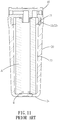
FIG. 11 comprises acontainer 20 having an interior provided with areceiving chamber 23 and having a top provided with anopening 21, atop cap 10 mounted on theopening 21 of thecontainer 20, and a filtering element A mounted in thereceiving chamber 23 of thecontainer 20. Thecontainer 20 has abottom 24 having a flat face. The top of thecontainer 20 has aninternal thread 22, and thetop cap 10 has anexternal thread 11 screwed into theinternal thread 22 of thecontainer 20. Thus, the filtering element A is located between thetop cap 10 and thebottom 24 of thecontainer 20. However, when the filtering element A has a greater length, thetop cap 10 and thebottom 24 of thecontainer 20 are pressed by the filtering element A, such that thebottom 24 of thecontainer 20 easily produces a crack B, thereby wearing and decreasing the lifetime of thecontainer 20. - The primary objective of the present invention is to provide a water purifier structure having a buffering effect to receive filter elements with different length.
- In accordance with the present invention, there is provided a water purifier structure comprising a container assembly and a buffer unit mounted in the container assembly. The container assembly includes a housing and a cap unit mounted on the housing. The housing has a first connecting portion. The housing has an interior provided with a first receiving section. The housing has a top provided with an opening. The housing has a bottom provided with a second receiving section. The bottom of the housing has an arcuate recessed shape. The second receiving section of the housing is provided with a retaining portion. The cap unit has a second connecting portion detachably connected with the first connecting portion of the housing. The buffer unit is mounted in the second receiving section of the housing. The buffer unit includes a positioning ring secured in the retaining portion of the housing, and a cushioning member elastically mounted in the positioning ring. The cushioning member is elastically movable in the positioning ring upward and downward. When the cushioning member is compressed by an external force, the cushioning member is contracted and elastically deformed toward the second receiving section of the housing, to form a buffering force.
- Further benefits and advantages of the present invention will become apparent after a careful reading of the detailed description with appropriate reference to the accompanying drawings.
- In the drawings:
-
FIG. 1 is an exploded perspective view of a water purifier structure in accordance with the preferred embodiment of the present invention. -
FIG. 2 is an exploded perspective view of a cap unit of the water purifier structure in accordance with the preferred embodiment of the present invention. -
FIG. 3 is a perspective view of a housing of the water purifier structure in accordance with the preferred embodiment of the present invention. -
FIG. 4 is a perspective view of the water purifier structure in accordance with the preferred embodiment of the present invention. -
FIG. 5 is a cross-sectional view and a locally enlarged view of the water purifier structure in accordance with the preferred embodiment of the present invention. -
FIG. 6 is a partial cross-sectional operational view of the water purifier structure in accordance with the preferred embodiment of the present invention. -
FIG. 7 is another partial cross-sectional operational view of the water purifier structure in accordance with the preferred embodiment of the present invention. -
FIG. 8 is a partial cross-sectional view of a water purifier structure in accordance with another preferred embodiment of the present invention. -
FIG. 9 is an exploded perspective view of a water purifier structure in accordance with a further preferred embodiment of the present invention. -
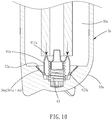
FIG. 10 is a partial cross-sectional assembly view of the water purifier structure as shown inFIG. 9 . -
FIG. 11 is a cross-sectional view of a conventional water purifier structure in accordance with the prior art. - Referring to the drawings and initially to
FIGS. 1-7 , a water purifier structure in accordance with the preferred embodiment of the present invention comprises acontainer assembly 7 and a buffer (or cushion)unit 4 mounted in thecontainer assembly 7. - The
container assembly 7 includes ahousing 3 and acap unit 5 mounted on thehousing 3. - The
housing 3 has a first connectingportion 32. Thehousing 3 has an interior provided with afirst receiving section 30 for mounting a filter element (or filter or filter cartridge) A. Thehousing 3 has a top provided with anopening 31 connected to thefirst receiving section 30. Thehousing 3 has abottom 33 provided with asecond receiving section 34 connected to thefirst receiving section 30. Thebottom 33 of thehousing 3 has an arcuate recessed shape. The second receivingsection 34 of thehousing 3 is provided with a retaining (or securing or fastening or locking) portion 342. - The
cap unit 5 has a second connectingportion 504 detachably connected with the first connectingportion 32 of thehousing 3. Thecap unit 5 includes acover 50, twoquick connectors 51, and two buckles (or fasteners or latches) 52 each having an inverted U-shape profile. Thecover 50 has an interior provided with achamber 506 which has a periphery provided with anannular groove 505. Thechamber 506 has an inverted U-shape profile. The second connectingportion 504 is formed in thechamber 506 of thecover 50. Thecover 50 has a top provided with awater inlet port 501 and awater outlet port 502 each having a snap-fit hole 503. - The
buffer unit 4 is mounted in thesecond receiving section 34 of thehousing 3. Thebuffer unit 4 includes apositioning ring 42 secured in the retaining portion 342 of thehousing 3, and a cushioning (or pressing or buffering)member 41 elastically mounted in thepositioning ring 42. Thecushioning member 41 is made of elastic material and is elastically movable in thepositioning ring 42 upward and downward. Thus, when thecushioning member 41 is compressed by an external force, thecushioning member 41 is contracted and elastically deformed toward the second receivingsection 34 of thehousing 3, to form a buffering (or cushioning) force. - In the preferred embodiment of the present invention, the
cushioning member 41 and thepositioning ring 42 of thebuffer unit 4 are connected detachably. Thecushioning member 41 has an upper end provided with apush portion 411 and a lower end provided with apressing portion 412. Thepush portion 411 of thecushioning member 41 is provided with a central cavity having an annular shape. Thepressing portion 412 of thecushioning member 41 has a conical (or tapered) shape. Thepositioning ring 42 has an interior provided with ahollow passage 421. Thepositioning ring 42 has an annular inner face provided with a plurality ofelastic plates 423 and has an outer face provided with a snap-fit portion 422 secured on the retaining portion 342 of thehousing 3. The snap-fit portion 422 of thepositioning ring 42 has a substantially U-shaped cross-sectional profile. Thepressing portion 412 of thecushioning member 41 is received in thehollow passage 421 of thepositioning ring 42 and is elastically pressed by theelastic plates 423 of thepositioning ring 42. Thepush portion 411 of thecushioning member 41 protrudes outward from a top of thepositioning ring 42. Thus, thecushioning member 41 is movable in thehollow passage 421 of thepositioning ring 42 and is deformed and flexed elastically due to a compressing force. - In the preferred embodiment of the present invention, the retaining portion 342 of the
housing 3 is a groove allowing insertion of thepositioning ring 42. - In the preferred embodiment of the present invention, the first connecting
portion 32 of thehousing 3 is an external thread, and the second connectingportion 504 of thecap unit 5 is an internal thread screwed onto the first connectingportion 32 of thehousing 3. - As shown in
FIG. 5 , each of the first connectingportion 32 of thehousing 3 and the second connectingportion 504 of thecap unit 5 has a discontinuous double threading X. When the second connectingportion 504 of thecap unit 5 is screwed onto the first connectingportion 32 of thehousing 3, the double threading X is kept at a line-to-line contact, such that the first connectingportion 32 of thehousing 3 and the second connectingportion 504 of thecap unit 5 are subjected to a force evenly, to enhance a screwing strength, and to prevent the double threading X from being loosened. Preferably, the double threading X has a root portion that is deformed to enhance engagement of the double threading X. - In assembly, one of two O-
rings 6 is mounted in theannular groove 505 of thecover 50 to provide an air-tight effect. Then, the other one of two O-rings 6 is mounted in the snap-fit portion 422 of thepositioning ring 42. Then, thebuffer unit 4 is mounted in thesecond receiving section 34 of thehousing 3 of thecontainer assembly 7, and thepositioning ring 42 of thebuffer unit 4 is secured in the retaining portion 342 of thehousing 3. At this time, the other one of two O-rings 6 is located between the snap-fit portion 422 of thepositioning ring 42 and the retaining portion 342 of thehousing 3. Then, the twoquick connectors 51 are respectively connected with thewater inlet port 501 and thewater outlet port 502 of thecover 50. Then, the twobuckles 52 are snapped into and locked in the snap-fit hole 503 to lock the twoquick connectors 51 respectively. Then, the second connectingportion 504 of thecap unit 5 is screwed onto the first connectingportion 32 of thehousing 3, such that thecap unit 5 is mounted on thehousing 3. Thus, assembly of the water purifier structure is finished. - Referring to
FIG. 6 with reference toFIGS. 1-5 , when thecap unit 5 is removed from thehousing 3, the filter element A is inserted through theopening 31 into thefirst receiving section 30 of thehousing 3. Then, thecap unit 5 is mounted on thehousing 3 again, such that the filter element A is located between thecap unit 5 and thehousing 3. At this time, the bottom of the filter element A rests on thepush portion 411 of the cushioningmember 41 of thebuffer unit 4. - Referring to
FIG. 7 , when the filter element A has a greater length, thepush portion 411 of the cushioningmember 41 is pressed by the filter element A. At this time, thepositioning ring 42 of thebuffer unit 4 is limited by the retaining portion 342 of thehousing 3, such that when thepush portion 411 of the cushioningmember 41 is compressed, the cushioningmember 41 of thebuffer unit 4 is moved downward relative to thepositioning ring 42, and thepressing portion 412 of the cushioningmember 41 is moved to press and contract theelastic plates 423 of thepositioning ring 42. In such a manner, when the cushioningmember 41 is pressed by the filter element A, the cushioningmember 41 is contracted and elastically deformed toward thesecond receiving section 34 of thehousing 3, to form a buffering force, such that the filter element A will not directly press the bottom 33 of thehousing 3, thereby preventing the bottom 33 of thehousing 3 from producing a crack. - Referring to
FIG. 8 , thechamber 506b of thecap unit 5b is provided with athird receiving section 507b connected to thefirst receiving section 30b. Thethird receiving section 507b of thecap unit 5b is provided with a retaining (or securing or fastening or locking)portion 508b. Thebuffer unit 4b is inserted into thethird receiving section 507b of thecap unit 5b. The second connectingportion 504b of thecap unit 5b is screwed onto the first connectingportion 32b of thehousing 3b, such that thecap unit 5b is mounted on thehousing 3b. In use, when the filter element has a greater length, thepush portion 411b of thebuffer unit 4b is pressed by the filter element. At this time, thepositioning ring 42b of thebuffer unit 4b is limited by the retainingportion 508b of thethird receiving section 507b of thecap unit 5b, such that when thepush portion 411b of thebuffer unit 4b is compressed, the cushioningmember 41b of thebuffer unit 4b is moved relative to thepositioning ring 42b, and thepressing portion 412b of the cushioningmember 41b is moved in thehollow passage 421b of thepositioning ring 42b to press and contract theelastic plates 423b of thepositioning ring 42b. In such a manner, when thebuffer unit 4b is pressed by the filter element, thebuffer unit 4b is contracted and elastically deformed, to form a buffering force. - Referring to
FIGS. 9 and10 , thehousing 3a has an interior provided with afirst receiving section 30a and has a top provided with anopening 31a connected to thefirst receiving section 30a. Thehousing 3a has a bottom 33a provided with asecond receiving section 34a connected to thefirst receiving section 30a. Thesecond receiving section 34a of thehousing 3a is provided with a retaining (or securing or fastening or locking) portion 342a. The retaining portion 342a of thehousing 3a includes a plurality of conical ribs arranged longitudinally and annularly. Thecap unit 5a is mounted on the first connectingportion 32a of thehousing 3a. The cushioningmember 41a and thepositioning ring 42a of thebuffer unit 4a are formed integrally. The cushioningmember 41a has an upper end provided with apush portion 411a. Thepositioning ring 42a has a conical shape and extends outward from a bottom of the cushioningmember 41a. The cushioningmember 41a and thepositioning ring 42a have a connection formed with a plurality ofelastic plates 423a. Thebuffer unit 4a further includes anelastic member 43 mounted in thesecond receiving section 34a of thehousing 3a and biased between a bottom of thesecond receiving section 34a and the cushioningmember 41a. In such a manner, theelastic plates 423a provide an elastic force so that when thebuffer unit 4a is compressed, the cushioningmember 41a is contracted and elastically deformed toward thesecond receiving section 34a of thehousing 3a, to form a buffering force. In addition, theelastic member 43 provides a restoring force to thebuffer unit 4a. - Accordingly, when the buffer unit is pressed by the filter element, the buffer unit is contracted and elastically deformed to form a buffering force to the filter element, such that the filter element will not directly press the bottom of the housing, thereby preventing the bottom of the housing from producing a crack, so as to enhance the lifetime of the housing. In addition, the housing is used to receive filter elements with different length. Further, the two
buckles 52 are snapped into and locked in the snap-fit hole 503 to lock the twoquick connectors 51 respectively, such that the twoquick connectors 51 are connected with thecover 50 quickly. - Although the invention has been explained in relation to its preferred embodiment(s) as mentioned above, it is to be understood that many other possible modifications and variations can be made without departing from the scope of the present invention. It is, therefore, contemplated that the appended claim or claims will cover such modifications and variations that fall within the scope of the invention.
Claims (9)
- A water purifier structure comprising:a container assembly (7); anda buffer unit (4) mounted in the container assembly;wherein:the container assembly includes a housing (3) and a cap unit (5) mounted on the housing;the housing has a first connecting portion (32);the housing has an interior provided with a first receiving section (30);the housing has a top provided with an opening (31);the housing has a bottom provided with a second receiving section (34);the bottom of the housing has an arcuate recessed shape;the second receiving section of the housing is provided with a retaining portion (342);the cap unit has a second connecting portion (504) detachably connected with the first connecting portion of the housing;the buffer unit is mounted in the second receiving section of the housing;the buffer unit includes a positioning ring (42) secured in the retaining portion of the housing, and a cushioning member (41) elastically mounted in the positioning ring;the cushioning member is elastically movable in the positioning ring upward and downward; andwhen the cushioning member is compressed by an external force, the cushioning member is contracted and elastically deformed toward the second receiving section of the housing, to form a buffering force.
- The water purifier structure of claim 1, wherein the chamber (506b) of the cap unit is provided with a third receiving section (507b) connected to the first receiving section (30b), the third receiving section of the cap unit (5b) is provided with a retaining portion (508b), and the buffer unit (4b) is inserted into the third receiving section of the cap unit.
- The water purifier structure of claim 1, wherein:the cushioning member and the positioning ring of the buffer unit are connected detachably;the cushioning member has an upper end provided with a push portion (411) and a lower end provided with a pressing portion (412);the push portion of the cushioning member is provided with a central cavity having an annular shape;the pressing portion of the cushioning member has a conical shape;the positioning ring has an interior provided with a hollow passage (421);the positioning ring has an annular inner face provided with a plurality of elastic plates (423) and has an outer face provided with a snap-fit portion (422) secured on the retaining portion of the housing;the pressing portion of the cushioning member is received in the hollow passage of the positioning ring and is elastically pressed by the elastic plates of the positioning ring; andthe push portion of the cushioning member protrudes outward from a top of the positioning ring.
- The water purifier structure of claim 1, wherein:the cushioning member and the positioning ring of the buffer unit are formed integrally;the cushioning member has an upper end provided with a push portion ();the positioning ring has a conical shape and extends outward from a bottom of the cushioning member;the cushioning member and the positioning ring have a connection formed with a plurality of elastic plates (423a); andthe buffer unit further includes an elastic member (43) mounted in the second receiving section of the housing and biased between a bottom of the second receiving section and the cushioning member.
- The water purifier structure of claim 1, wherein the retaining portion of the housing is a groove allowing insertion of the positioning ring.
- The water purifier structure of claim 4, wherein the retaining portion of the housing includes a plurality of conical ribs arranged longitudinally and annularly.
- The water purifier structure of claim 1, wherein:each of the first connecting portion of the housing and the second connecting portion of the cap unit has a discontinuous double threading (X); andwhen the second connecting portion of the cap unit is screwed onto the first connecting portion of the housing, the double threading is kept at a line-to-line contact, such that the first connecting portion of the housing and the second connecting portion of the cap unit are subjected to a force evenly.
- The water purifier structure of claim 7, wherein the double threading has a root portion that is deformed.
- The water purifier structure of claim 1, wherein the cap unit includes a cover (50) provided with a water inlet port (501) and a water outlet port (502), two quick connectors (51) connected with the water inlet port and the water outlet port of the cover, and two buckles (52) connecting the two quick connectors with the cover.
Applications Claiming Priority (1)
| Application Number | Priority Date | Filing Date | Title |
|---|---|---|---|
| TW108200850U TWM578614U (en) | 2019-01-17 | 2019-01-17 | Filtering cylinder structure of water purifier |
Publications (2)
| Publication Number | Publication Date |
|---|---|
| EP3682960A1 true EP3682960A1 (en) | 2020-07-22 |
| EP3682960B1 EP3682960B1 (en) | 2022-08-31 |
Family
ID=67702989
Family Applications (1)
| Application Number | Title | Priority Date | Filing Date |
|---|---|---|---|
| EP19197678.6A Active EP3682960B1 (en) | 2019-01-17 | 2019-09-17 | Water purifier structure |
Country Status (3)
| Country | Link |
|---|---|
| EP (1) | EP3682960B1 (en) |
| GB (1) | GB2576984B (en) |
| TW (1) | TWM578614U (en) |
Citations (4)
| Publication number | Priority date | Publication date | Assignee | Title |
|---|---|---|---|---|
| US3923663A (en) * | 1974-07-22 | 1975-12-02 | William P Reid | Fluid purification device |
| US7033502B2 (en) * | 2000-01-12 | 2006-04-25 | Rct Technologies Llc | UV lamp supported filter cartridge |
| GB2504501A (en) * | 2012-07-31 | 2014-02-05 | Charles Joseph Williamson | Jug water filter cartridge |
| WO2018121090A1 (en) * | 2016-12-30 | 2018-07-05 | 福州品行科技发展有限公司 | Water filter capable of purifying water without being affected by disassembling, and use method thereof |
Family Cites Families (1)
| Publication number | Priority date | Publication date | Assignee | Title |
|---|---|---|---|---|
| KR20120038281A (en) * | 2010-10-13 | 2012-04-23 | 웅진케미칼 주식회사 | Connecter for assembling filter sump |
-
2019
- 2019-01-17 TW TW108200850U patent/TWM578614U/en unknown
- 2019-09-11 GB GB1913077.2A patent/GB2576984B/en active Active
- 2019-09-17 EP EP19197678.6A patent/EP3682960B1/en active Active
Patent Citations (4)
| Publication number | Priority date | Publication date | Assignee | Title |
|---|---|---|---|---|
| US3923663A (en) * | 1974-07-22 | 1975-12-02 | William P Reid | Fluid purification device |
| US7033502B2 (en) * | 2000-01-12 | 2006-04-25 | Rct Technologies Llc | UV lamp supported filter cartridge |
| GB2504501A (en) * | 2012-07-31 | 2014-02-05 | Charles Joseph Williamson | Jug water filter cartridge |
| WO2018121090A1 (en) * | 2016-12-30 | 2018-07-05 | 福州品行科技发展有限公司 | Water filter capable of purifying water without being affected by disassembling, and use method thereof |
Also Published As
| Publication number | Publication date |
|---|---|
| TWM578614U (en) | 2019-06-01 |
| GB2576984A (en) | 2020-03-11 |
| GB2576984B (en) | 2023-09-06 |
| GB201913077D0 (en) | 2019-10-23 |
| EP3682960B1 (en) | 2022-08-31 |
Similar Documents
| Publication | Publication Date | Title |
|---|---|---|
| US11697081B2 (en) | Water purifier structure | |
| CN113646961B (en) | Relief valve for reducing pressure generated in a chamber-like cavity, such as a battery block | |
| US9724631B2 (en) | Filter element adaptor for compressed air filter | |
| KR101948325B1 (en) | Pressure release valve assembly for pressure cooker | |
| US20150238887A1 (en) | Upper end cap for filter | |
| US20160040812A1 (en) | Quick Connector Structure for a Pipe | |
| US10058000B2 (en) | Waterproof structure for casing of electronic device | |
| EP3682960B1 (en) | Water purifier structure | |
| US7695618B2 (en) | Filter cartridge and mounting system therefor having foolproofing means | |
| US20080191057A1 (en) | Sanitary line connection | |
| US11069330B2 (en) | Tone bar of a percussion instrument and associated connecting element | |
| CA2405021A1 (en) | Pipette with simplified disassembly | |
| US20050000296A1 (en) | Fastening arrangement for a sensor at a receptacle | |
| US5758678A (en) | Stabilized umbrella top structure | |
| US20180099524A1 (en) | Wheel Disk Structure | |
| JP5501861B2 (en) | Manufacturing method of pump | |
| CN205240242U (en) | Press press pump | |
| JP6547207B2 (en) | Aerosol container | |
| KR20100001249U (en) | Leg Locks for Conference Tables | |
| JP7430215B2 (en) | Watch case with a back oriented in a predetermined angular position, a watch including said case, and a method for assembling such a case | |
| JP2003028352A (en) | Container valve | |
| KR101531470B1 (en) | Vacuum Container for Storing Food | |
| US20050243654A1 (en) | Ratchet assembly device for fitting a back cover and/or a bezel onto a watch case middle | |
| CN210397387U (en) | Briquetting plug screw and O type circle assembly structure | |
| CN210012617U (en) | Water purifier filter bottle structure |
Legal Events
| Date | Code | Title | Description |
|---|---|---|---|
| PUAI | Public reference made under article 153(3) epc to a published international application that has entered the european phase |
Free format text: ORIGINAL CODE: 0009012 |
|
| STAA | Information on the status of an ep patent application or granted ep patent |
Free format text: STATUS: REQUEST FOR EXAMINATION WAS MADE |
|
| 17P | Request for examination filed |
Effective date: 20190917 |
|
| AK | Designated contracting states |
Kind code of ref document: A1 Designated state(s): AL AT BE BG CH CY CZ DE DK EE ES FI FR GB GR HR HU IE IS IT LI LT LU LV MC MK MT NL NO PL PT RO RS SE SI SK SM TR |
|
| AX | Request for extension of the european patent |
Extension state: BA ME |
|
| STAA | Information on the status of an ep patent application or granted ep patent |
Free format text: STATUS: EXAMINATION IS IN PROGRESS |
|
| 17Q | First examination report despatched |
Effective date: 20210119 |
|
| GRAP | Despatch of communication of intention to grant a patent |
Free format text: ORIGINAL CODE: EPIDOSNIGR1 |
|
| STAA | Information on the status of an ep patent application or granted ep patent |
Free format text: STATUS: GRANT OF PATENT IS INTENDED |
|
| INTG | Intention to grant announced |
Effective date: 20220406 |
|
| GRAJ | Information related to disapproval of communication of intention to grant by the applicant or resumption of examination proceedings by the epo deleted |
Free format text: ORIGINAL CODE: EPIDOSDIGR1 |
|
| STAA | Information on the status of an ep patent application or granted ep patent |
Free format text: STATUS: EXAMINATION IS IN PROGRESS |
|
| INTC | Intention to grant announced (deleted) | ||
| GRAS | Grant fee paid |
Free format text: ORIGINAL CODE: EPIDOSNIGR3 |
|
| STAA | Information on the status of an ep patent application or granted ep patent |
Free format text: STATUS: GRANT OF PATENT IS INTENDED |
|
| GRAP | Despatch of communication of intention to grant a patent |
Free format text: ORIGINAL CODE: EPIDOSNIGR1 |
|
| GRAA | (expected) grant |
Free format text: ORIGINAL CODE: 0009210 |
|
| STAA | Information on the status of an ep patent application or granted ep patent |
Free format text: STATUS: THE PATENT HAS BEEN GRANTED |
|
| INTG | Intention to grant announced |
Effective date: 20220719 |
|
| AK | Designated contracting states |
Kind code of ref document: B1 Designated state(s): AL AT BE BG CH CY CZ DE DK EE ES FI FR GB GR HR HU IE IS IT LI LT LU LV MC MK MT NL NO PL PT RO RS SE SI SK SM TR |
|
| REG | Reference to a national code |
Ref country code: CH Ref legal event code: EP Ref country code: GB Ref legal event code: FG4D |
|
| REG | Reference to a national code |
Ref country code: AT Ref legal event code: REF Ref document number: 1514888 Country of ref document: AT Kind code of ref document: T Effective date: 20220915 |
|
| REG | Reference to a national code |
Ref country code: DE Ref legal event code: R096 Ref document number: 602019018887 Country of ref document: DE |
|
| REG | Reference to a national code |
Ref country code: IE Ref legal event code: FG4D |
|
| REG | Reference to a national code |
Ref country code: LT Ref legal event code: MG9D |
|
| REG | Reference to a national code |
Ref country code: NL Ref legal event code: MP Effective date: 20220831 |
|
| PG25 | Lapsed in a contracting state [announced via postgrant information from national office to epo] |
Ref country code: SE Free format text: LAPSE BECAUSE OF FAILURE TO SUBMIT A TRANSLATION OF THE DESCRIPTION OR TO PAY THE FEE WITHIN THE PRESCRIBED TIME-LIMIT Effective date: 20220831 Ref country code: RS Free format text: LAPSE BECAUSE OF FAILURE TO SUBMIT A TRANSLATION OF THE DESCRIPTION OR TO PAY THE FEE WITHIN THE PRESCRIBED TIME-LIMIT Effective date: 20220831 Ref country code: NO Free format text: LAPSE BECAUSE OF FAILURE TO SUBMIT A TRANSLATION OF THE DESCRIPTION OR TO PAY THE FEE WITHIN THE PRESCRIBED TIME-LIMIT Effective date: 20221130 Ref country code: LV Free format text: LAPSE BECAUSE OF FAILURE TO SUBMIT A TRANSLATION OF THE DESCRIPTION OR TO PAY THE FEE WITHIN THE PRESCRIBED TIME-LIMIT Effective date: 20220831 Ref country code: LT Free format text: LAPSE BECAUSE OF FAILURE TO SUBMIT A TRANSLATION OF THE DESCRIPTION OR TO PAY THE FEE WITHIN THE PRESCRIBED TIME-LIMIT Effective date: 20220831 Ref country code: FI Free format text: LAPSE BECAUSE OF FAILURE TO SUBMIT A TRANSLATION OF THE DESCRIPTION OR TO PAY THE FEE WITHIN THE PRESCRIBED TIME-LIMIT Effective date: 20220831 |
|
| REG | Reference to a national code |
Ref country code: AT Ref legal event code: MK05 Ref document number: 1514888 Country of ref document: AT Kind code of ref document: T Effective date: 20220831 |
|
| PG25 | Lapsed in a contracting state [announced via postgrant information from national office to epo] |
Ref country code: PL Free format text: LAPSE BECAUSE OF FAILURE TO SUBMIT A TRANSLATION OF THE DESCRIPTION OR TO PAY THE FEE WITHIN THE PRESCRIBED TIME-LIMIT Effective date: 20220831 Ref country code: IS Free format text: LAPSE BECAUSE OF FAILURE TO SUBMIT A TRANSLATION OF THE DESCRIPTION OR TO PAY THE FEE WITHIN THE PRESCRIBED TIME-LIMIT Effective date: 20221231 Ref country code: HR Free format text: LAPSE BECAUSE OF FAILURE TO SUBMIT A TRANSLATION OF THE DESCRIPTION OR TO PAY THE FEE WITHIN THE PRESCRIBED TIME-LIMIT Effective date: 20220831 Ref country code: GR Free format text: LAPSE BECAUSE OF FAILURE TO SUBMIT A TRANSLATION OF THE DESCRIPTION OR TO PAY THE FEE WITHIN THE PRESCRIBED TIME-LIMIT Effective date: 20221201 |
|
| PG25 | Lapsed in a contracting state [announced via postgrant information from national office to epo] |
Ref country code: SM Free format text: LAPSE BECAUSE OF FAILURE TO SUBMIT A TRANSLATION OF THE DESCRIPTION OR TO PAY THE FEE WITHIN THE PRESCRIBED TIME-LIMIT Effective date: 20220831 Ref country code: RO Free format text: LAPSE BECAUSE OF FAILURE TO SUBMIT A TRANSLATION OF THE DESCRIPTION OR TO PAY THE FEE WITHIN THE PRESCRIBED TIME-LIMIT Effective date: 20220831 Ref country code: PT Free format text: LAPSE BECAUSE OF FAILURE TO SUBMIT A TRANSLATION OF THE DESCRIPTION OR TO PAY THE FEE WITHIN THE PRESCRIBED TIME-LIMIT Effective date: 20230102 Ref country code: ES Free format text: LAPSE BECAUSE OF FAILURE TO SUBMIT A TRANSLATION OF THE DESCRIPTION OR TO PAY THE FEE WITHIN THE PRESCRIBED TIME-LIMIT Effective date: 20220831 Ref country code: DK Free format text: LAPSE BECAUSE OF FAILURE TO SUBMIT A TRANSLATION OF THE DESCRIPTION OR TO PAY THE FEE WITHIN THE PRESCRIBED TIME-LIMIT Effective date: 20220831 Ref country code: CZ Free format text: LAPSE BECAUSE OF FAILURE TO SUBMIT A TRANSLATION OF THE DESCRIPTION OR TO PAY THE FEE WITHIN THE PRESCRIBED TIME-LIMIT Effective date: 20220831 Ref country code: AT Free format text: LAPSE BECAUSE OF FAILURE TO SUBMIT A TRANSLATION OF THE DESCRIPTION OR TO PAY THE FEE WITHIN THE PRESCRIBED TIME-LIMIT Effective date: 20220831 |
|
| REG | Reference to a national code |
Ref country code: CH Ref legal event code: PL |
|
| REG | Reference to a national code |
Ref country code: BE Ref legal event code: MM Effective date: 20220930 |
|
| PG25 | Lapsed in a contracting state [announced via postgrant information from national office to epo] |
Ref country code: SK Free format text: LAPSE BECAUSE OF FAILURE TO SUBMIT A TRANSLATION OF THE DESCRIPTION OR TO PAY THE FEE WITHIN THE PRESCRIBED TIME-LIMIT Effective date: 20220831 Ref country code: MC Free format text: LAPSE BECAUSE OF FAILURE TO SUBMIT A TRANSLATION OF THE DESCRIPTION OR TO PAY THE FEE WITHIN THE PRESCRIBED TIME-LIMIT Effective date: 20220831 Ref country code: EE Free format text: LAPSE BECAUSE OF FAILURE TO SUBMIT A TRANSLATION OF THE DESCRIPTION OR TO PAY THE FEE WITHIN THE PRESCRIBED TIME-LIMIT Effective date: 20220831 |
|
| REG | Reference to a national code |
Ref country code: DE Ref legal event code: R097 Ref document number: 602019018887 Country of ref document: DE |
|
| PG25 | Lapsed in a contracting state [announced via postgrant information from national office to epo] |
Ref country code: NL Free format text: LAPSE BECAUSE OF FAILURE TO SUBMIT A TRANSLATION OF THE DESCRIPTION OR TO PAY THE FEE WITHIN THE PRESCRIBED TIME-LIMIT Effective date: 20220831 Ref country code: LU Free format text: LAPSE BECAUSE OF NON-PAYMENT OF DUE FEES Effective date: 20220917 Ref country code: AL Free format text: LAPSE BECAUSE OF FAILURE TO SUBMIT A TRANSLATION OF THE DESCRIPTION OR TO PAY THE FEE WITHIN THE PRESCRIBED TIME-LIMIT Effective date: 20220831 |
|
| PLBE | No opposition filed within time limit |
Free format text: ORIGINAL CODE: 0009261 |
|
| STAA | Information on the status of an ep patent application or granted ep patent |
Free format text: STATUS: NO OPPOSITION FILED WITHIN TIME LIMIT |
|
| PG25 | Lapsed in a contracting state [announced via postgrant information from national office to epo] |
Ref country code: LI Free format text: LAPSE BECAUSE OF NON-PAYMENT OF DUE FEES Effective date: 20220930 Ref country code: IE Free format text: LAPSE BECAUSE OF NON-PAYMENT OF DUE FEES Effective date: 20220917 Ref country code: CH Free format text: LAPSE BECAUSE OF NON-PAYMENT OF DUE FEES Effective date: 20220930 |
|
| 26N | No opposition filed |
Effective date: 20230601 |
|
| PG25 | Lapsed in a contracting state [announced via postgrant information from national office to epo] |
Ref country code: SI Free format text: LAPSE BECAUSE OF FAILURE TO SUBMIT A TRANSLATION OF THE DESCRIPTION OR TO PAY THE FEE WITHIN THE PRESCRIBED TIME-LIMIT Effective date: 20220831 |
|
| PG25 | Lapsed in a contracting state [announced via postgrant information from national office to epo] |
Ref country code: BE Free format text: LAPSE BECAUSE OF NON-PAYMENT OF DUE FEES Effective date: 20220930 |
|
| PG25 | Lapsed in a contracting state [announced via postgrant information from national office to epo] |
Ref country code: CY Free format text: LAPSE BECAUSE OF FAILURE TO SUBMIT A TRANSLATION OF THE DESCRIPTION OR TO PAY THE FEE WITHIN THE PRESCRIBED TIME-LIMIT Effective date: 20220831 |
|
| PG25 | Lapsed in a contracting state [announced via postgrant information from national office to epo] |
Ref country code: MK Free format text: LAPSE BECAUSE OF FAILURE TO SUBMIT A TRANSLATION OF THE DESCRIPTION OR TO PAY THE FEE WITHIN THE PRESCRIBED TIME-LIMIT Effective date: 20220831 Ref country code: IT Free format text: LAPSE BECAUSE OF FAILURE TO SUBMIT A TRANSLATION OF THE DESCRIPTION OR TO PAY THE FEE WITHIN THE PRESCRIBED TIME-LIMIT Effective date: 20220831 Ref country code: HU Free format text: LAPSE BECAUSE OF FAILURE TO SUBMIT A TRANSLATION OF THE DESCRIPTION OR TO PAY THE FEE WITHIN THE PRESCRIBED TIME-LIMIT; INVALID AB INITIO Effective date: 20190917 |
|
| PG25 | Lapsed in a contracting state [announced via postgrant information from national office to epo] |
Ref country code: TR Free format text: LAPSE BECAUSE OF FAILURE TO SUBMIT A TRANSLATION OF THE DESCRIPTION OR TO PAY THE FEE WITHIN THE PRESCRIBED TIME-LIMIT Effective date: 20220831 |
|
| PG25 | Lapsed in a contracting state [announced via postgrant information from national office to epo] |
Ref country code: BG Free format text: LAPSE BECAUSE OF FAILURE TO SUBMIT A TRANSLATION OF THE DESCRIPTION OR TO PAY THE FEE WITHIN THE PRESCRIBED TIME-LIMIT Effective date: 20220831 |
|
| REG | Reference to a national code |
Ref country code: DE Ref legal event code: R082 Ref document number: 602019018887 Country of ref document: DE |
|
| PG25 | Lapsed in a contracting state [announced via postgrant information from national office to epo] |
Ref country code: MT Free format text: LAPSE BECAUSE OF FAILURE TO SUBMIT A TRANSLATION OF THE DESCRIPTION OR TO PAY THE FEE WITHIN THE PRESCRIBED TIME-LIMIT Effective date: 20220831 |
|
| PGFP | Annual fee paid to national office [announced via postgrant information from national office to epo] |
Ref country code: DE Payment date: 20250818 Year of fee payment: 7 |
|
| PGFP | Annual fee paid to national office [announced via postgrant information from national office to epo] |
Ref country code: GB Payment date: 20250819 Year of fee payment: 7 |
|
| PGFP | Annual fee paid to national office [announced via postgrant information from national office to epo] |
Ref country code: FR Payment date: 20250819 Year of fee payment: 7 |