EP3682756B1 - Wearable electronic device assembly - Google Patents
Wearable electronic device assembly Download PDFInfo
- Publication number
- EP3682756B1 EP3682756B1 EP20152312.3A EP20152312A EP3682756B1 EP 3682756 B1 EP3682756 B1 EP 3682756B1 EP 20152312 A EP20152312 A EP 20152312A EP 3682756 B1 EP3682756 B1 EP 3682756B1
- Authority
- EP
- European Patent Office
- Prior art keywords
- securement
- strap
- assembly according
- connector
- projection
- Prior art date
- Legal status (The legal status is an assumption and is not a legal conclusion. Google has not performed a legal analysis and makes no representation as to the accuracy of the status listed.)
- Active
Links
Images






Classifications
-
- G—PHYSICS
- G04—HOROLOGY
- G04G—ELECTRONIC TIME-PIECES
- G04G17/00—Structural details; Housings
- G04G17/02—Component assemblies
-
- A—HUMAN NECESSITIES
- A44—HABERDASHERY; JEWELLERY
- A44C—PERSONAL ADORNMENTS, e.g. JEWELLERY; COINS
- A44C5/00—Bracelets; Wrist-watch straps; Fastenings for bracelets or wrist-watch straps
- A44C5/14—Bracelets; Wrist-watch straps; Fastenings for bracelets or wrist-watch straps characterised by the way of fastening to a wrist-watch or the like
-
- A—HUMAN NECESSITIES
- A44—HABERDASHERY; JEWELLERY
- A44B—BUTTONS, PINS, BUCKLES, SLIDE FASTENERS, OR THE LIKE
- A44B11/00—Buckles; Similar fasteners for interconnecting straps or the like, e.g. for safety belts
- A44B11/006—Attachment of buckle to strap
-
- A—HUMAN NECESSITIES
- A44—HABERDASHERY; JEWELLERY
- A44B—BUTTONS, PINS, BUCKLES, SLIDE FASTENERS, OR THE LIKE
- A44B11/00—Buckles; Similar fasteners for interconnecting straps or the like, e.g. for safety belts
- A44B11/20—Buckles; Similar fasteners for interconnecting straps or the like, e.g. for safety belts engaging holes or the like in strap
- A44B11/22—Buckle with fixed prong
-
- A—HUMAN NECESSITIES
- A44—HABERDASHERY; JEWELLERY
- A44B—BUTTONS, PINS, BUCKLES, SLIDE FASTENERS, OR THE LIKE
- A44B11/00—Buckles; Similar fasteners for interconnecting straps or the like, e.g. for safety belts
- A44B11/25—Buckles; Similar fasteners for interconnecting straps or the like, e.g. for safety belts with two or more separable parts
- A44B11/258—Buckles; Similar fasteners for interconnecting straps or the like, e.g. for safety belts with two or more separable parts fastening by superposing one part on top of the other
-
- A—HUMAN NECESSITIES
- A44—HABERDASHERY; JEWELLERY
- A44B—BUTTONS, PINS, BUCKLES, SLIDE FASTENERS, OR THE LIKE
- A44B11/00—Buckles; Similar fasteners for interconnecting straps or the like, e.g. for safety belts
- A44B11/25—Buckles; Similar fasteners for interconnecting straps or the like, e.g. for safety belts with two or more separable parts
- A44B11/258—Buckles; Similar fasteners for interconnecting straps or the like, e.g. for safety belts with two or more separable parts fastening by superposing one part on top of the other
- A44B11/2584—Buckles; Similar fasteners for interconnecting straps or the like, e.g. for safety belts with two or more separable parts fastening by superposing one part on top of the other followed by sliding in the main plane of the buckle
-
- A—HUMAN NECESSITIES
- A44—HABERDASHERY; JEWELLERY
- A44B—BUTTONS, PINS, BUCKLES, SLIDE FASTENERS, OR THE LIKE
- A44B11/00—Buckles; Similar fasteners for interconnecting straps or the like, e.g. for safety belts
- A44B11/25—Buckles; Similar fasteners for interconnecting straps or the like, e.g. for safety belts with two or more separable parts
- A44B11/26—Buckles; Similar fasteners for interconnecting straps or the like, e.g. for safety belts with two or more separable parts with push-button fastenings
- A44B11/263—Buckles; Similar fasteners for interconnecting straps or the like, e.g. for safety belts with two or more separable parts with push-button fastenings with a push-button acting perpendicularly to the main plane of the buckle
-
- A—HUMAN NECESSITIES
- A44—HABERDASHERY; JEWELLERY
- A44B—BUTTONS, PINS, BUCKLES, SLIDE FASTENERS, OR THE LIKE
- A44B11/00—Buckles; Similar fasteners for interconnecting straps or the like, e.g. for safety belts
- A44B11/25—Buckles; Similar fasteners for interconnecting straps or the like, e.g. for safety belts with two or more separable parts
- A44B11/26—Buckles; Similar fasteners for interconnecting straps or the like, e.g. for safety belts with two or more separable parts with push-button fastenings
- A44B11/266—Buckles; Similar fasteners for interconnecting straps or the like, e.g. for safety belts with two or more separable parts with push-button fastenings with at least one push-button acting parallel to the main plane of the buckle and perpendicularly to the direction of the fastening action
-
- A—HUMAN NECESSITIES
- A44—HABERDASHERY; JEWELLERY
- A44C—PERSONAL ADORNMENTS, e.g. JEWELLERY; COINS
- A44C5/00—Bracelets; Wrist-watch straps; Fastenings for bracelets or wrist-watch straps
- A44C5/0053—Flexible straps
-
- A—HUMAN NECESSITIES
- A44—HABERDASHERY; JEWELLERY
- A44C—PERSONAL ADORNMENTS, e.g. JEWELLERY; COINS
- A44C5/00—Bracelets; Wrist-watch straps; Fastenings for bracelets or wrist-watch straps
- A44C5/18—Fasteners for straps, chains or the like
- A44C5/20—Fasteners for straps, chains or the like for open straps, chains or the like
- A44C5/2052—Fasteners provided with at least one push-button acting parallel to the main plane of the fastener and perpendicularly to the direction of the fastening
-
- A—HUMAN NECESSITIES
- A44—HABERDASHERY; JEWELLERY
- A44C—PERSONAL ADORNMENTS, e.g. JEWELLERY; COINS
- A44C5/00—Bracelets; Wrist-watch straps; Fastenings for bracelets or wrist-watch straps
- A44C5/18—Fasteners for straps, chains or the like
- A44C5/20—Fasteners for straps, chains or the like for open straps, chains or the like
- A44C5/2066—Fasteners with locking means acting parallel to the main plane of the fastener and perpendicularly to the direction of the fastening
-
- A—HUMAN NECESSITIES
- A44—HABERDASHERY; JEWELLERY
- A44C—PERSONAL ADORNMENTS, e.g. JEWELLERY; COINS
- A44C5/00—Bracelets; Wrist-watch straps; Fastenings for bracelets or wrist-watch straps
- A44C5/18—Fasteners for straps, chains or the like
- A44C5/20—Fasteners for straps, chains or the like for open straps, chains or the like
- A44C5/2071—Fasteners for straps, chains or the like for open straps, chains or the like with the two ends of the strap or chain overlapping each other and fastened by an action perpendicularly to the main plane of these two ends
-
- G—PHYSICS
- G04—HOROLOGY
- G04G—ELECTRONIC TIME-PIECES
- G04G21/00—Input or output devices integrated in time-pieces
- G04G21/04—Input or output devices integrated in time-pieces using radio waves
Definitions
- the present invention relates to a wearable electronic device assembly.
- the electronic device preferably comprises a radio frequency (RF) tag or transponder device, e.g. for a real-time location system.
- RF radio frequency
- the invention is relevant to other types of electronic devices, and to multi-function electronic devices, including computing devices, mobile telephone devices, watches, etc.
- the device preferably is wearable on a wrist of a user, but additionally or alternatively it may be worn on the ankle, or wherever convenient or suitable.
- the device may additionally or alternatively be worn by a non-human animal (e.g. a dog, a cat, or livestock), e.g. around the neck of the animal.
- US 9 314 072 B2 discloses a strap for a wristwatch.
- a pin plate which is removably affixed to the strap includes a pin, where the pin plate is adapted to be affixed to the other strap in an orientation to define a distance between the pin and the proximal end of the strap.
- the pin plate is adapted to be affixed to the strap in another orientation to define another distance between the pin and the proximal end of the strap, where both the distances are different from each other.
- an electronic device e.g. an RF tag or transponder
- a wearer e.g. a vulnerable medical patient, elderly person, baby, or animal.
- the present invention seeks to provide an assembly which enables this.
- a first aspect of the present invention provides a wearable electronic device assembly according to Claim 1 of the appendant claims.
- a second aspect of the invention provides a kit of parts comprising the wearable device assembly and a tool, according to Claim 14.
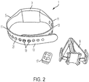
- Figures 1 and 2 show an example of a wearable electronic device assembly 1 according to the invention, comprising an electronic device 3, a strap 5 attached to the device for attaching the device to a wearer (e.g. to the wearer's wrist), and a connector 7 (shown in more detail in figures 3 to 9 ) for securing together two overlapping end regions of the strap. Also shown is a tool 9 (shown in more detail in figures 10 to 12 ) for subsequently enabling the disconnection of the connector 7 from the end regions of the strap.
- the electronic device 3 preferably comprises a radio frequency tag or transponder device, e.g. for a real-time location system.
- the electronic device 3 could be a multi-functional electronic device, or another type of electronic device. Examples include computing devices, mobile telephone devices, watches, etc.
- the strap 5 comprises two strap portions 11, each strap portion 11 attached to a respective one of two opposite sides of the electronic device 3.
- the strap 5 has two end regions 13, in this example each end region 13 comprising all or most of the length of a respective strap portion 11.
- the two end regions 13 of the strap 5 are arranged to be brought together in overlapping configuration, e.g. as illustrated in figures 1 and 2 .
- the connector 7 comprises a first part 15 and a second part 17, illustrated in more detail in figures 3 to 9 .
- the first part 15 of the connector 7 has one or more (two, in the illustrated example) projections 19 arranged to extend through or adjacent to the strap 5.
- Each end region 13 of the illustrated strap 5 has a series of spaced holes 21 extending through the strap.
- the projections 19 and the holes 21 are arranged so as to allow the projections to extend through selected holes (and thus through or adjacent to the strap itself), particular holes being selected for a wearer according to size, so that the size of the loop (formed by the strap 5 and the electronic device 3), created when the end regions 13 are overlapped and connected together by the connector 7, is correct for securement on the wearer (e.g. around the wearer's wrist).
- holes 21 through the strap 5 there could be recesses or projections in or on the strap.
- the projections 19 could extend through the recesses and adjacent to the strap.
- the second part 17 of the connector 7 is then secured to the first part 15 of the connector 7 with the two overlapping end regions 13 of the strap 5 extending between them, thereby securing the two overlapping end regions 13 of the strap 5 together. In this way, the electronic device 3 is secured to the wearer.
- FIG. 3 to 9 illustrate the example connector 7 and its components in greater detail.
- the connector 7 comprises a first part 15 and a second part 17.
- the first part 15 comprises a pair of projections 19 arranged to extend through or adjacent to the strap 5 (e.g. through selected holes 21 in the strap 5).
- the second part 17 of the illustrated connector 7 comprises a main body 23 having a pair of apertures 25 to receive respective projections 19 therein.
- the second part 17 of this embodiment of the invention includes a pair of securement parts 27 retained by, and movable (preferably by sliding) with respect to, the main body 23.
- the securement parts 27 are at least partly housed in the hollow main body 23.
- Each projection 19 of the first part 15 of the connector 7 includes an engagement protrusion 29.
- each engagement protrusion 29 has the form of a circular flange; however, other shapes are possible.
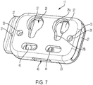
- each aperture 25 in the second part 17 of the connector 7 has a relatively wide portion 25a and a relatively narrow portion 25b extending from the relatively narrow portion.
- the relatively wide and narrow portions give the apertures 25 a key-hole type shape.
- the relatively wide portion 25a of each aperture 25 is sized to allow the engagement protrusion 29 of its respective projection 19 to pass therethrough.
- each aperture 25 is sized to prevent the engagement protrusion 29 of its respective projection 19 to pass therethrough, thereby to retain the projection 19 in the relatively narrow portion 25b of the aperture 25 of the second part 17 of the connector 7, by engagement of the engagement protrusion 29 with the main body 23 of the second part 17 of the connector 7.
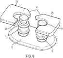
- Each securement part 27 of the second part 17 of the connector 7 is retained by, and movable with respect to, the main body 23 between a release position and a securement position.
- the lefthand illustrated securement part 27a is shown in its release position
- the righthand illustrated securement part 27b is shown in its securement position.
- a securement part 27 retains its respective projection 19 in the relatively narrow portion 25b of the aperture 25, by blocking lateral movement of the projection 19 in the aperture 25.
- the engagement protrusion 29 of a projection 19 engages with its respective securement part 27, to block such lateral movement of the projection 19.
- the first and second parts of the connector 7 are secured together with the two overlapping end regions 13 of the strap 5 extending between them, by inserting the projections 19 of the first part 15 of the connector 7 into the relatively wide portions 25a of the apertures 25 and moving the second part 17 of the connector 7 laterally with respect to the first part 15 of the connector, to locate the projections 19 in the relatively narrow portions 25b of the apertures.
- Each securement part 27 is then moved with respect to the main body 23 of the second part 17 of the connector 7 from its release position to its securement position, thereby to block any movement of the projections 19 from the relatively narrow portions 25b of the apertures 25 to the relatively wide portions 25a of the apertures.
- the first part 15 of the connector 7 is thereby secured to the second part 17 of the connector 7, and the two overlapping end regions 13 of the strap are thereby secured together.
- each securement part 27 includes a protuberance 31 arranged to locate in a corresponding opening 33 in the main body 23 of the second part 17 of the connector 7 when the securement part is in its securement position, thereby releasably securing the securement part in its securement position.
- the protuberance could be on the main body 23, and the opening in the securement part 27.
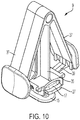
- a particular tool 9 may be used.
- the example tool 9 comprises a central arm 35 configured to temporarily fit onto the second part 17 of the connector 7, and two lateral arms 37 configured to be flexed or otherwise moved by the user such that a finger 39 projecting from each lateral arm 37 may be inserted through an opening 40 into the main body 23 of the second part 17 of the connector 7.
- each securement part 27 includes a first cam surface 41.
- each finger 39 of the tool 9 includes cam surfaces 43, such that when, in use, the cam surfaces 43 of the fingers 39 are pushed against the first cam surfaces 41 of the securement parts 27, the securement parts are moved from their securement positions to their release positions.
- the securement parts 27 may include second cam surfaces 45 which may be contacted and pushed by another tool, e.g. an end of a paper clip or the like, to move the securement parts 27 from their securement positions to their release positions.
- the optional requirement to use a specific tool, or at least a paper clip or the like as a tool provides an additional level of security of attachment of the electronic device to the wearer, to prevent unsafe or unauthorized removal of the device, while allowing easy removal by use of the specific tool, or by a certain minimum level of understanding, manual dexterity and visual acuity by use of a paper clip or the like.
Landscapes
- Physics & Mathematics (AREA)
- General Physics & Mathematics (AREA)
- Telephone Set Structure (AREA)
Description
- The present invention relates to a wearable electronic device assembly. The electronic device preferably comprises a radio frequency (RF) tag or transponder device, e.g. for a real-time location system. However, the invention is relevant to other types of electronic devices, and to multi-function electronic devices, including computing devices, mobile telephone devices, watches, etc.
- The device preferably is wearable on a wrist of a user, but additionally or alternatively it may be worn on the ankle, or wherever convenient or suitable. The device may additionally or alternatively be worn by a non-human animal (e.g. a dog, a cat, or livestock), e.g. around the neck of the animal.
-
US 9 314 072 B2 - There is a need for the secure but releasable attachment of an electronic device (e.g. an RF tag or transponder) to a wearer (e.g. a vulnerable medical patient, elderly person, baby, or animal). The present invention seeks to provide an assembly which enables this.
- A first aspect of the present invention provides a wearable electronic device assembly according to Claim 1 of the appendant claims.
- A second aspect of the invention provides a kit of parts comprising the wearable device assembly and a tool, according to Claim 14.
- Preferred, and other optional, features of the invention are described and defined in the dependent claims.
- An embodiment of the invention will now be described, by way of example, with reference to the accompanying drawings, of which:
-
Figs. 1 and2 show a wearable electronic device assembly and tool, according to the invention; -
Figs. 3 to 9 show views of components of the connector of the wearable device assembly according to the invention; and -
Figs. 10 to 12 show views of the tool, and components of the connector, according to the invention. -
Figures 1 and2 show an example of a wearable electronic device assembly 1 according to the invention, comprising anelectronic device 3, astrap 5 attached to the device for attaching the device to a wearer (e.g. to the wearer's wrist), and a connector 7 (shown in more detail infigures 3 to 9 ) for securing together two overlapping end regions of the strap. Also shown is a tool 9 (shown in more detail infigures 10 to 12 ) for subsequently enabling the disconnection of theconnector 7 from the end regions of the strap. Theelectronic device 3 preferably comprises a radio frequency tag or transponder device, e.g. for a real-time location system. However, as mentioned above, theelectronic device 3 could be a multi-functional electronic device, or another type of electronic device. Examples include computing devices, mobile telephone devices, watches, etc. - The
strap 5 comprises twostrap portions 11, eachstrap portion 11 attached to a respective one of two opposite sides of theelectronic device 3. Thestrap 5 has twoend regions 13, in this example eachend region 13 comprising all or most of the length of arespective strap portion 11. The twoend regions 13 of thestrap 5 are arranged to be brought together in overlapping configuration, e.g. as illustrated infigures 1 and2 . Theconnector 7 comprises afirst part 15 and asecond part 17, illustrated in more detail infigures 3 to 9 . Thefirst part 15 of theconnector 7 has one or more (two, in the illustrated example)projections 19 arranged to extend through or adjacent to thestrap 5. Eachend region 13 of the illustratedstrap 5 has a series of spacedholes 21 extending through the strap. Theprojections 19 and theholes 21 are arranged so as to allow the projections to extend through selected holes (and thus through or adjacent to the strap itself), particular holes being selected for a wearer according to size, so that the size of the loop (formed by thestrap 5 and the electronic device 3), created when theend regions 13 are overlapped and connected together by theconnector 7, is correct for securement on the wearer (e.g. around the wearer's wrist). (Additionally or alternatively toholes 21 through thestrap 5, there could be recesses or projections in or on the strap. If lateral recesses are used, for example, theprojections 19 could extend through the recesses and adjacent to the strap.) Thesecond part 17 of theconnector 7 is then secured to thefirst part 15 of theconnector 7 with the two overlappingend regions 13 of thestrap 5 extending between them, thereby securing the two overlappingend regions 13 of thestrap 5 together. In this way, theelectronic device 3 is secured to the wearer. -
Figures 3 to 9 illustrate theexample connector 7 and its components in greater detail. Theconnector 7 comprises afirst part 15 and asecond part 17. In the illustrated example, thefirst part 15 comprises a pair ofprojections 19 arranged to extend through or adjacent to the strap 5 (e.g. through selectedholes 21 in the strap 5). Thesecond part 17 of the illustratedconnector 7 comprises amain body 23 having a pair ofapertures 25 to receiverespective projections 19 therein. Additionally, thesecond part 17 of this embodiment of the invention includes a pair of securementparts 27 retained by, and movable (preferably by sliding) with respect to, themain body 23. In the illustrated embodiment, the securementparts 27 are at least partly housed in the hollowmain body 23. - Each
projection 19 of thefirst part 15 of theconnector 7 includes anengagement protrusion 29. In the illustrated embodiment of the invention, eachengagement protrusion 29 has the form of a circular flange; however, other shapes are possible. As shown inFigure 7 , eachaperture 25 in thesecond part 17 of theconnector 7 has a relativelywide portion 25a and a relativelynarrow portion 25b extending from the relatively narrow portion. In the illustrated embodiment of the invention, the relatively wide and narrow portions give theapertures 25 a key-hole type shape. The relativelywide portion 25a of eachaperture 25 is sized to allow theengagement protrusion 29 of itsrespective projection 19 to pass therethrough. The relativelynarrow portion 25b of eachaperture 25 is sized to prevent theengagement protrusion 29 of itsrespective projection 19 to pass therethrough, thereby to retain theprojection 19 in the relativelynarrow portion 25b of theaperture 25 of thesecond part 17 of theconnector 7, by engagement of theengagement protrusion 29 with themain body 23 of thesecond part 17 of theconnector 7. - Each securement
part 27 of thesecond part 17 of theconnector 7 is retained by, and movable with respect to, themain body 23 between a release position and a securement position. InFigure 8 , the lefthand illustrated securementpart 27a is shown in its release position, whereas the righthand illustrated securementpart 27b is shown in its securement position. In the securement position, asecurement part 27 retains itsrespective projection 19 in the relativelynarrow portion 25b of theaperture 25, by blocking lateral movement of theprojection 19 in theaperture 25. In the illustrated example embodiment, theengagement protrusion 29 of aprojection 19 engages with its respective securementpart 27, to block such lateral movement of theprojection 19. - Consequently, the first and second parts of the
connector 7 are secured together with the two overlappingend regions 13 of thestrap 5 extending between them, by inserting theprojections 19 of thefirst part 15 of theconnector 7 into the relativelywide portions 25a of theapertures 25 and moving thesecond part 17 of theconnector 7 laterally with respect to thefirst part 15 of the connector, to locate theprojections 19 in the relativelynarrow portions 25b of the apertures. Each securementpart 27 is then moved with respect to themain body 23 of thesecond part 17 of theconnector 7 from its release position to its securement position, thereby to block any movement of theprojections 19 from the relativelynarrow portions 25b of theapertures 25 to the relativelywide portions 25a of the apertures. Thefirst part 15 of theconnector 7 is thereby secured to thesecond part 17 of theconnector 7, and the two overlappingend regions 13 of the strap are thereby secured together. - As shown in
figures 7 and9 , each securementpart 27 includes aprotuberance 31 arranged to locate in acorresponding opening 33 in themain body 23 of thesecond part 17 of theconnector 7 when the securement part is in its securement position, thereby releasably securing the securement part in its securement position. (Additionally or alternatively, the protuberance could be on themain body 23, and the opening in thesecurement part 27.) - In order to move the, or each, securement
part 27 from its securement position to its release position, thereby allowing the first and second parts of theconnector 7 to be separated to allow thestrap 5 to be opened and theelectronic device 3 removed from the wearer, aparticular tool 9 may be used. As illustrated infigures 10 and11 , theexample tool 9 comprises acentral arm 35 configured to temporarily fit onto thesecond part 17 of theconnector 7, and twolateral arms 37 configured to be flexed or otherwise moved by the user such that afinger 39 projecting from eachlateral arm 37 may be inserted through anopening 40 into themain body 23 of thesecond part 17 of theconnector 7. As shown infigures 8 ,9 and12 , each securementpart 27 includes afirst cam surface 41. As shown inFigure 12 , eachfinger 39 of thetool 9 includescam surfaces 43, such that when, in use, thecam surfaces 43 of thefingers 39 are pushed against thefirst cam surfaces 41 of the securementparts 27, the securement parts are moved from their securement positions to their release positions. Additionally or alternatively, the securementparts 27 may includesecond cam surfaces 45 which may be contacted and pushed by another tool, e.g. an end of a paper clip or the like, to move the securementparts 27 from their securement positions to their release positions. - The optional requirement to use a specific tool, or at least a paper clip or the like as a tool, provides an additional level of security of attachment of the electronic device to the wearer, to prevent unsafe or unauthorized removal of the device, while allowing easy removal by use of the specific tool, or by a certain minimum level of understanding, manual dexterity and visual acuity by use of a paper clip or the like.
- It will be understood that the above description and the drawings are of a particular example embodiment of the invention, but that other embodiments of the invention are included as long as they fall within the scope of the claims.
Claims (15)
- A wearable electronic device assembly (1), comprising: an electronic device (3); a strap (5) attached to the device for attaching the device to a wearer, the strap having two end regions arranged to be brought together in overlapping configuration; and a connector (7) comprising first (15) and second (17) parts configured to be secured together with the two overlapping end regions (13) of the strap extending between them, thereby to secure the two overlapping end regions of the strap together; the first part of the connector comprising a projection arranged to extend through or adjacent to the strap; and the second part of the connector comprising a main body having an aperture to receive the projection of the first part therein, and a securement part (27) retained by and movable with respect to the main body between a release position and a securement position; wherein the projection has an engagement protrusion configured to engage with the main body and/or with the securement part when the securement part is in its securement position, to retain the projection in the aperture (25) of the second part of the connector and thereby secure the first part of the connector to the second part of the connector.
- An assembly according to Claim 1, wherein the engagement protrusion is releasable or released from its engagement with the main body and/or with the securement part when the securement part is in its release position.
- An assembly according to Claim 1 or Claim 2, wherein the securement part is slidable with respect to the main body of the second part of the connector.
- An assembly according to any preceding claim, wherein the securement part is releasably securable in its securement position.
- An assembly according to Claim 4, wherein the securement part is releasably securable in its securement position by means of a protuberance on the securement part or on the main body catching in an opening or depression in the main body or in the securement part, respectively.
- An assembly according to any preceding claim, wherein the aperture has a relatively wide portion sized to allow the engagement protrusion of the projection to pass therethrough, and a relatively narrow portion extending from the relatively wide portion, the relatively narrow portion sized to prevent the engagement protrusion of the projection passing therethrough thereby to retain the projection in the relatively narrow portion of the aperture of the second part of the connector.
- An assembly according to Claim 6, wherein the securement part retains the projection in the relatively narrow portion of the aperture when the securement part is in its securement position.
- An assembly according to any preceding claim, wherein the securement part substantially blocks movement of the projection in the aperture when the securement part is in its securement position.
- An assembly according to any preceding claim, wherein one or both end regions of the strap have a series of spaced holes extending therethrough, through each of which the projection may selectively extend, thereby to secure the two overlapping end regions of the strap together in any of a plurality of degrees of overlap.
- An assembly according to any preceding claim, wherein the securement part includes one or more cam surfaces configured to enable the securement part to be moved from its securement position to its release position.
- An assembly according to any preceding claim, wherein there is a plurality of said projections and respective said apertures.
- An assembly according to the immediately preceding claim, wherein there is a plurality of said securement parts.
- An assembly according to any preceding claim, wherein the strap comprises one or more strap portions, preferably two strap portions, each strap portion attached to a respective one of two opposite sides of the device, preferably wherein each end region of the strap comprises a respective strap portion.
- A kit of parts comprising an assembly according to any preceding claim, and a tool for moving the, or each, securement part from its securement position to its release position.
- A kit according to the immediately preceding claim, wherein the securement part(s) and/or the tool have one or more cam surfaces configured to cause movement of the securement part from its securement position to its release position when the tool acts on the securement part(s) in use.
Applications Claiming Priority (1)
| Application Number | Priority Date | Filing Date | Title |
|---|---|---|---|
| GBGB1900798.8A GB201900798D0 (en) | 2019-01-21 | 2019-01-21 | Wearable electronic device assembly |
Publications (2)
| Publication Number | Publication Date |
|---|---|
| EP3682756A1 EP3682756A1 (en) | 2020-07-22 |
| EP3682756B1 true EP3682756B1 (en) | 2021-09-29 |
Family
ID=65528137
Family Applications (1)
| Application Number | Title | Priority Date | Filing Date |
|---|---|---|---|
| EP20152312.3A Active EP3682756B1 (en) | 2019-01-21 | 2020-01-16 | Wearable electronic device assembly |
Country Status (3)
| Country | Link |
|---|---|
| US (2) | US11191327B2 (en) |
| EP (1) | EP3682756B1 (en) |
| GB (1) | GB201900798D0 (en) |
Families Citing this family (7)
| Publication number | Priority date | Publication date | Assignee | Title |
|---|---|---|---|---|
| USD1077661S1 (en) * | 2020-12-03 | 2025-06-03 | Fitbit, Inc. | Fitness tracker |
| USD1111872S1 (en) * | 2021-07-02 | 2026-02-10 | Google Llc | Wearable device |
| US12368267B2 (en) | 2021-09-15 | 2025-07-22 | Apple Inc. | Connector having a release button |
| USD1017461S1 (en) * | 2022-05-12 | 2024-03-12 | Modl, Inc. | Strap link |
| EP4615225A1 (en) * | 2022-12-16 | 2025-09-17 | Hill's Pet Nutrition, Inc. | Wearable animal information apparatus |
| USD1017377S1 (en) * | 2023-05-12 | 2024-03-12 | Modl, Inc. | Strap link |
| US12329251B2 (en) * | 2023-07-10 | 2025-06-17 | Yanghui Zheng | Watchband connector |
Family Cites Families (10)
| Publication number | Priority date | Publication date | Assignee | Title |
|---|---|---|---|---|
| US1543399A (en) * | 1922-09-26 | 1925-06-23 | Merle Powe Smith | Wrist-watch band |
| US1498126A (en) * | 1922-11-23 | 1924-06-17 | Merle Powe Smith | Wrist-watch band |
| US4221063A (en) * | 1976-07-06 | 1980-09-09 | Precision Dynamics Corporation | Tamper-resistant identification device |
| US5189763A (en) * | 1990-07-13 | 1993-03-02 | Isafrance | Strap clasp |
| US5226809A (en) | 1992-01-13 | 1993-07-13 | Precision Dynamics Corporation | Security fastener application |
| EP2928339B1 (en) * | 2012-12-05 | 2017-06-14 | Preziosi Point SAGL | Watchstrap, fastening system for a watchstrap and corresponding watch |
| US9314072B2 (en) | 2013-01-31 | 2016-04-19 | Salutron, Inc. | Reversible pin plate for fine wrist strap adjustment |
| US10039350B2 (en) * | 2016-05-11 | 2018-08-07 | Szu Chi Lo | Strap buckle structure |
| CN105815895B (en) | 2016-05-19 | 2018-11-09 | 青岛歌尔声学科技有限公司 | A kind of wearing product band attachment structure |
| JP2018117922A (en) | 2017-01-26 | 2018-08-02 | セイコーインスツル株式会社 | Portable device case, portable device, and watch |
-
2019
- 2019-01-21 GB GBGB1900798.8A patent/GB201900798D0/en not_active Ceased
- 2019-12-30 US US16/730,152 patent/US11191327B2/en active Active
-
2020
- 2020-01-16 EP EP20152312.3A patent/EP3682756B1/en active Active
-
2021
- 2021-11-03 US US17/453,421 patent/US11607016B2/en active Active
Also Published As
| Publication number | Publication date |
|---|---|
| US11191327B2 (en) | 2021-12-07 |
| US11607016B2 (en) | 2023-03-21 |
| EP3682756A1 (en) | 2020-07-22 |
| US20220053893A1 (en) | 2022-02-24 |
| GB201900798D0 (en) | 2019-03-06 |
| US20200229552A1 (en) | 2020-07-23 |
Similar Documents
| Publication | Publication Date | Title |
|---|---|---|
| US11607016B2 (en) | Wearable electronic device assembly | |
| DE602005007187D1 (en) | Wrist bandage with straps in the form of uninterrupted loops and procedures for their placement | |
| DE102021126552B4 (en) | Glove and wearable sensor device comprising a glove and an electronic module | |
| US20130098955A1 (en) | Resilient Arm or Leg Band with Semi-transparent Pocket and Concealed Fastenings | |
| US6192708B1 (en) | Finger ring insert | |
| EP3157372B1 (en) | Adjustable watch strap | |
| US20170127772A1 (en) | Systems, methods, and devices for securing a hair retention device hidden from view using a bracelet | |
| EP3593666B1 (en) | Dual watchband buckle capable of achieving fine adjustment of length of watchband | |
| EP3960020B1 (en) | Watchband and watch case; and watch | |
| US20230355421A1 (en) | Arm immobilizing sleep garment device | |
| CN105901849A (en) | Watch with extending watchband | |
| GB2529581A (en) | Fastening Device | |
| WO2016197020A1 (en) | Multiple device wrist band | |
| US6513685B1 (en) | Ring securing device | |
| US20150254967A1 (en) | Tracking and monitoring system | |
| US9226551B2 (en) | Locking clasp requiring wearer assistance for removal | |
| WO2002045537A1 (en) | Prayer strand marker | |
| US10813418B1 (en) | Lanyard with double fastener | |
| GB1576793A (en) | Clasp assembly | |
| US11717039B2 (en) | Immobilizing sleep garment assembly | |
| JP4142884B2 (en) | Wristband clip | |
| BG3319U1 (en) | Adjustable watch band / chain for a smart watch, gps tracker or another wrist monitoring device | |
| US20210120892A1 (en) | Finger guard | |
| JPS6117680A (en) | Key | |
| JP4589573B2 (en) | Wristband clip |
Legal Events
| Date | Code | Title | Description |
|---|---|---|---|
| PUAI | Public reference made under article 153(3) epc to a published international application that has entered the european phase |
Free format text: ORIGINAL CODE: 0009012 |
|
| STAA | Information on the status of an ep patent application or granted ep patent |
Free format text: STATUS: THE APPLICATION HAS BEEN PUBLISHED |
|
| AK | Designated contracting states |
Kind code of ref document: A1 Designated state(s): AL AT BE BG CH CY CZ DE DK EE ES FI FR GB GR HR HU IE IS IT LI LT LU LV MC MK MT NL NO PL PT RO RS SE SI SK SM TR |
|
| AX | Request for extension of the european patent |
Extension state: BA ME |
|
| STAA | Information on the status of an ep patent application or granted ep patent |
Free format text: STATUS: REQUEST FOR EXAMINATION WAS MADE |
|
| 17P | Request for examination filed |
Effective date: 20210120 |
|
| RBV | Designated contracting states (corrected) |
Designated state(s): AL AT BE BG CH CY CZ DE DK EE ES FI FR GB GR HR HU IE IS IT LI LT LU LV MC MK MT NL NO PL PT RO RS SE SI SK SM TR |
|
| REG | Reference to a national code |
Ref country code: DE Ref legal event code: R079 Ref document number: 602020000607 Country of ref document: DE Free format text: PREVIOUS MAIN CLASS: A44C0005000000 Ipc: G04G0017020000 |
|
| GRAP | Despatch of communication of intention to grant a patent |
Free format text: ORIGINAL CODE: EPIDOSNIGR1 |
|
| STAA | Information on the status of an ep patent application or granted ep patent |
Free format text: STATUS: GRANT OF PATENT IS INTENDED |
|
| RIC1 | Information provided on ipc code assigned before grant |
Ipc: G04G 17/02 20060101AFI20210525BHEP Ipc: A44C 5/00 20060101ALI20210525BHEP Ipc: A44C 5/20 20060101ALI20210525BHEP Ipc: G04G 21/04 20130101ALI20210525BHEP |
|
| INTG | Intention to grant announced |
Effective date: 20210610 |
|
| RIN1 | Information on inventor provided before grant (corrected) |
Inventor name: KALMANOVICH, ALEXEY Inventor name: AMSALEM, REUVEN |
|
| GRAS | Grant fee paid |
Free format text: ORIGINAL CODE: EPIDOSNIGR3 |
|
| GRAA | (expected) grant |
Free format text: ORIGINAL CODE: 0009210 |
|
| STAA | Information on the status of an ep patent application or granted ep patent |
Free format text: STATUS: THE PATENT HAS BEEN GRANTED |
|
| AK | Designated contracting states |
Kind code of ref document: B1 Designated state(s): AL AT BE BG CH CY CZ DE DK EE ES FI FR GB GR HR HU IE IS IT LI LT LU LV MC MK MT NL NO PL PT RO RS SE SI SK SM TR |
|
| REG | Reference to a national code |
Ref country code: GB Ref legal event code: FG4D |
|
| REG | Reference to a national code |
Ref country code: DE Ref legal event code: R096 Ref document number: 602020000607 Country of ref document: DE |
|
| REG | Reference to a national code |
Ref country code: CH Ref legal event code: EP Ref country code: AT Ref legal event code: REF Ref document number: 1434741 Country of ref document: AT Kind code of ref document: T Effective date: 20211015 |
|
| REG | Reference to a national code |
Ref country code: IE Ref legal event code: FG4D |
|
| REG | Reference to a national code |
Ref country code: LT Ref legal event code: MG9D |
|
| PG25 | Lapsed in a contracting state [announced via postgrant information from national office to epo] |
Ref country code: SE Free format text: LAPSE BECAUSE OF FAILURE TO SUBMIT A TRANSLATION OF THE DESCRIPTION OR TO PAY THE FEE WITHIN THE PRESCRIBED TIME-LIMIT Effective date: 20210929 Ref country code: RS Free format text: LAPSE BECAUSE OF FAILURE TO SUBMIT A TRANSLATION OF THE DESCRIPTION OR TO PAY THE FEE WITHIN THE PRESCRIBED TIME-LIMIT Effective date: 20210929 Ref country code: LT Free format text: LAPSE BECAUSE OF FAILURE TO SUBMIT A TRANSLATION OF THE DESCRIPTION OR TO PAY THE FEE WITHIN THE PRESCRIBED TIME-LIMIT Effective date: 20210929 Ref country code: BG Free format text: LAPSE BECAUSE OF FAILURE TO SUBMIT A TRANSLATION OF THE DESCRIPTION OR TO PAY THE FEE WITHIN THE PRESCRIBED TIME-LIMIT Effective date: 20211229 Ref country code: FI Free format text: LAPSE BECAUSE OF FAILURE TO SUBMIT A TRANSLATION OF THE DESCRIPTION OR TO PAY THE FEE WITHIN THE PRESCRIBED TIME-LIMIT Effective date: 20210929 Ref country code: HR Free format text: LAPSE BECAUSE OF FAILURE TO SUBMIT A TRANSLATION OF THE DESCRIPTION OR TO PAY THE FEE WITHIN THE PRESCRIBED TIME-LIMIT Effective date: 20210929 Ref country code: NO Free format text: LAPSE BECAUSE OF FAILURE TO SUBMIT A TRANSLATION OF THE DESCRIPTION OR TO PAY THE FEE WITHIN THE PRESCRIBED TIME-LIMIT Effective date: 20211229 |
|
| REG | Reference to a national code |
Ref country code: NL Ref legal event code: MP Effective date: 20210929 |
|
| REG | Reference to a national code |
Ref country code: AT Ref legal event code: MK05 Ref document number: 1434741 Country of ref document: AT Kind code of ref document: T Effective date: 20210929 |
|
| PG25 | Lapsed in a contracting state [announced via postgrant information from national office to epo] |
Ref country code: LV Free format text: LAPSE BECAUSE OF FAILURE TO SUBMIT A TRANSLATION OF THE DESCRIPTION OR TO PAY THE FEE WITHIN THE PRESCRIBED TIME-LIMIT Effective date: 20210929 Ref country code: GR Free format text: LAPSE BECAUSE OF FAILURE TO SUBMIT A TRANSLATION OF THE DESCRIPTION OR TO PAY THE FEE WITHIN THE PRESCRIBED TIME-LIMIT Effective date: 20211230 |
|
| PG25 | Lapsed in a contracting state [announced via postgrant information from national office to epo] |
Ref country code: AT Free format text: LAPSE BECAUSE OF FAILURE TO SUBMIT A TRANSLATION OF THE DESCRIPTION OR TO PAY THE FEE WITHIN THE PRESCRIBED TIME-LIMIT Effective date: 20210929 |
|
| PG25 | Lapsed in a contracting state [announced via postgrant information from national office to epo] |
Ref country code: IS Free format text: LAPSE BECAUSE OF FAILURE TO SUBMIT A TRANSLATION OF THE DESCRIPTION OR TO PAY THE FEE WITHIN THE PRESCRIBED TIME-LIMIT Effective date: 20220129 Ref country code: SK Free format text: LAPSE BECAUSE OF FAILURE TO SUBMIT A TRANSLATION OF THE DESCRIPTION OR TO PAY THE FEE WITHIN THE PRESCRIBED TIME-LIMIT Effective date: 20210929 Ref country code: RO Free format text: LAPSE BECAUSE OF FAILURE TO SUBMIT A TRANSLATION OF THE DESCRIPTION OR TO PAY THE FEE WITHIN THE PRESCRIBED TIME-LIMIT Effective date: 20210929 Ref country code: PT Free format text: LAPSE BECAUSE OF FAILURE TO SUBMIT A TRANSLATION OF THE DESCRIPTION OR TO PAY THE FEE WITHIN THE PRESCRIBED TIME-LIMIT Effective date: 20220131 Ref country code: PL Free format text: LAPSE BECAUSE OF FAILURE TO SUBMIT A TRANSLATION OF THE DESCRIPTION OR TO PAY THE FEE WITHIN THE PRESCRIBED TIME-LIMIT Effective date: 20210929 Ref country code: NL Free format text: LAPSE BECAUSE OF FAILURE TO SUBMIT A TRANSLATION OF THE DESCRIPTION OR TO PAY THE FEE WITHIN THE PRESCRIBED TIME-LIMIT Effective date: 20210929 Ref country code: ES Free format text: LAPSE BECAUSE OF FAILURE TO SUBMIT A TRANSLATION OF THE DESCRIPTION OR TO PAY THE FEE WITHIN THE PRESCRIBED TIME-LIMIT Effective date: 20210929 Ref country code: EE Free format text: LAPSE BECAUSE OF FAILURE TO SUBMIT A TRANSLATION OF THE DESCRIPTION OR TO PAY THE FEE WITHIN THE PRESCRIBED TIME-LIMIT Effective date: 20210929 Ref country code: CZ Free format text: LAPSE BECAUSE OF FAILURE TO SUBMIT A TRANSLATION OF THE DESCRIPTION OR TO PAY THE FEE WITHIN THE PRESCRIBED TIME-LIMIT Effective date: 20210929 Ref country code: AL Free format text: LAPSE BECAUSE OF FAILURE TO SUBMIT A TRANSLATION OF THE DESCRIPTION OR TO PAY THE FEE WITHIN THE PRESCRIBED TIME-LIMIT Effective date: 20210929 |
|
| REG | Reference to a national code |
Ref country code: DE Ref legal event code: R097 Ref document number: 602020000607 Country of ref document: DE |
|
| PG25 | Lapsed in a contracting state [announced via postgrant information from national office to epo] |
Ref country code: DK Free format text: LAPSE BECAUSE OF FAILURE TO SUBMIT A TRANSLATION OF THE DESCRIPTION OR TO PAY THE FEE WITHIN THE PRESCRIBED TIME-LIMIT Effective date: 20210929 |
|
| PLBE | No opposition filed within time limit |
Free format text: ORIGINAL CODE: 0009261 |
|
| STAA | Information on the status of an ep patent application or granted ep patent |
Free format text: STATUS: NO OPPOSITION FILED WITHIN TIME LIMIT |
|
| PG25 | Lapsed in a contracting state [announced via postgrant information from national office to epo] |
Ref country code: MC Free format text: LAPSE BECAUSE OF FAILURE TO SUBMIT A TRANSLATION OF THE DESCRIPTION OR TO PAY THE FEE WITHIN THE PRESCRIBED TIME-LIMIT Effective date: 20210929 |
|
| 26N | No opposition filed |
Effective date: 20220630 |
|
| REG | Reference to a national code |
Ref country code: BE Ref legal event code: MM Effective date: 20220131 |
|
| PG25 | Lapsed in a contracting state [announced via postgrant information from national office to epo] |
Ref country code: LU Free format text: LAPSE BECAUSE OF NON-PAYMENT OF DUE FEES Effective date: 20220116 |
|
| PG25 | Lapsed in a contracting state [announced via postgrant information from national office to epo] |
Ref country code: SI Free format text: LAPSE BECAUSE OF FAILURE TO SUBMIT A TRANSLATION OF THE DESCRIPTION OR TO PAY THE FEE WITHIN THE PRESCRIBED TIME-LIMIT Effective date: 20210929 Ref country code: FR Free format text: LAPSE BECAUSE OF NON-PAYMENT OF DUE FEES Effective date: 20220131 Ref country code: BE Free format text: LAPSE BECAUSE OF NON-PAYMENT OF DUE FEES Effective date: 20220131 |
|
| PG25 | Lapsed in a contracting state [announced via postgrant information from national office to epo] |
Ref country code: IT Free format text: LAPSE BECAUSE OF FAILURE TO SUBMIT A TRANSLATION OF THE DESCRIPTION OR TO PAY THE FEE WITHIN THE PRESCRIBED TIME-LIMIT Effective date: 20210929 Ref country code: IE Free format text: LAPSE BECAUSE OF NON-PAYMENT OF DUE FEES Effective date: 20220116 |
|
| REG | Reference to a national code |
Ref country code: CH Ref legal event code: PL |
|
| PG25 | Lapsed in a contracting state [announced via postgrant information from national office to epo] |
Ref country code: LI Free format text: LAPSE BECAUSE OF NON-PAYMENT OF DUE FEES Effective date: 20230131 Ref country code: CH Free format text: LAPSE BECAUSE OF NON-PAYMENT OF DUE FEES Effective date: 20230131 |
|
| PG25 | Lapsed in a contracting state [announced via postgrant information from national office to epo] |
Ref country code: SM Free format text: LAPSE BECAUSE OF FAILURE TO SUBMIT A TRANSLATION OF THE DESCRIPTION OR TO PAY THE FEE WITHIN THE PRESCRIBED TIME-LIMIT Effective date: 20210929 Ref country code: MK Free format text: LAPSE BECAUSE OF FAILURE TO SUBMIT A TRANSLATION OF THE DESCRIPTION OR TO PAY THE FEE WITHIN THE PRESCRIBED TIME-LIMIT Effective date: 20210929 Ref country code: CY Free format text: LAPSE BECAUSE OF FAILURE TO SUBMIT A TRANSLATION OF THE DESCRIPTION OR TO PAY THE FEE WITHIN THE PRESCRIBED TIME-LIMIT Effective date: 20210929 |
|
| PG25 | Lapsed in a contracting state [announced via postgrant information from national office to epo] |
Ref country code: HU Free format text: LAPSE BECAUSE OF FAILURE TO SUBMIT A TRANSLATION OF THE DESCRIPTION OR TO PAY THE FEE WITHIN THE PRESCRIBED TIME-LIMIT; INVALID AB INITIO Effective date: 20200116 |
|
| PG25 | Lapsed in a contracting state [announced via postgrant information from national office to epo] |
Ref country code: MT Free format text: LAPSE BECAUSE OF FAILURE TO SUBMIT A TRANSLATION OF THE DESCRIPTION OR TO PAY THE FEE WITHIN THE PRESCRIBED TIME-LIMIT Effective date: 20210929 |
|
| PG25 | Lapsed in a contracting state [announced via postgrant information from national office to epo] |
Ref country code: TR Free format text: LAPSE BECAUSE OF FAILURE TO SUBMIT A TRANSLATION OF THE DESCRIPTION OR TO PAY THE FEE WITHIN THE PRESCRIBED TIME-LIMIT Effective date: 20210929 |
|
| PGFP | Annual fee paid to national office [announced via postgrant information from national office to epo] |
Ref country code: GB Payment date: 20260127 Year of fee payment: 7 |
|
| PGFP | Annual fee paid to national office [announced via postgrant information from national office to epo] |
Ref country code: DE Payment date: 20260128 Year of fee payment: 7 |