EP3682735A1 - Dog toilet - Google Patents
Dog toilet Download PDFInfo
- Publication number
- EP3682735A1 EP3682735A1 EP18890120.1A EP18890120A EP3682735A1 EP 3682735 A1 EP3682735 A1 EP 3682735A1 EP 18890120 A EP18890120 A EP 18890120A EP 3682735 A1 EP3682735 A1 EP 3682735A1
- Authority
- EP
- European Patent Office
- Prior art keywords
- electrode
- dog
- positive electrode
- negative electrode
- dog toilet
- Prior art date
- Legal status (The legal status is an assumption and is not a legal conclusion. Google has not performed a legal analysis and makes no representation as to the accuracy of the status listed.)
- Granted
Links
Images





Classifications
-
- A—HUMAN NECESSITIES
- A01—AGRICULTURE; FORESTRY; ANIMAL HUSBANDRY; HUNTING; TRAPPING; FISHING
- A01K—ANIMAL HUSBANDRY; AVICULTURE; APICULTURE; PISCICULTURE; FISHING; REARING OR BREEDING ANIMALS, NOT OTHERWISE PROVIDED FOR; NEW BREEDS OF ANIMALS
- A01K1/00—Housing animals; Equipment therefor
- A01K1/01—Removal of dung or urine ; Removal of manure from stables
-
- A—HUMAN NECESSITIES
- A01—AGRICULTURE; FORESTRY; ANIMAL HUSBANDRY; HUNTING; TRAPPING; FISHING
- A01K—ANIMAL HUSBANDRY; AVICULTURE; APICULTURE; PISCICULTURE; FISHING; REARING OR BREEDING ANIMALS, NOT OTHERWISE PROVIDED FOR; NEW BREEDS OF ANIMALS
- A01K1/00—Housing animals; Equipment therefor
- A01K1/01—Removal of dung or urine ; Removal of manure from stables
- A01K1/0107—Cat trays; Dog urinals; Toilets for pets
-
- A—HUMAN NECESSITIES
- A01—AGRICULTURE; FORESTRY; ANIMAL HUSBANDRY; HUNTING; TRAPPING; FISHING
- A01K—ANIMAL HUSBANDRY; AVICULTURE; APICULTURE; PISCICULTURE; FISHING; REARING OR BREEDING ANIMALS, NOT OTHERWISE PROVIDED FOR; NEW BREEDS OF ANIMALS
- A01K29/00—Other apparatus for animal husbandry
- A01K29/005—Monitoring or measuring activity
-
- A—HUMAN NECESSITIES
- A01—AGRICULTURE; FORESTRY; ANIMAL HUSBANDRY; HUNTING; TRAPPING; FISHING
- A01K—ANIMAL HUSBANDRY; AVICULTURE; APICULTURE; PISCICULTURE; FISHING; REARING OR BREEDING ANIMALS, NOT OTHERWISE PROVIDED FOR; NEW BREEDS OF ANIMALS
- A01K5/00—Feeding devices for stock or game ; Feeding wagons; Feeding stacks
- A01K5/02—Automatic devices
Definitions
- the present invention relates to a dog toilet.
- a toilet described in Patent Literature 1 includes: a urination detection sensor provided in a bottom portion; and a feeder (operating device) that operates on the basis of a detection result of the urination detection sensor. When the urination detection sensor detects excretion by an animal, the feeder operates to supply food.
- Patent Literature 1 Japanese Patent Application Publication No. 2009-45053
- the present invention was achieved in light of conventional problems such as that described above, and an aspect of the present invention is to provide a dog toilet capable of preventing erroneous operation of an operating device.
- a dog toilet including:
- a dog toilet including:
- an insulating member is arranged between the receptacle and at least either one of the first electrode and the second electrode.
- the insulating member is arranged between the first electrode and the second electrode.
- a non-absorbent material is used as the insulating member.
- the first electrode and the second electrode are both spaced apart from the receptacle, and an absorbent member is arranged below the first electrode and the second electrode, the absorbent member including a liquid-absorbent, absorbent body.
- the absorbent member With such a dog toilet, it is possible for the absorbent member to absorb urine adhered to the electrodes. This can suppress the smell of urine, for example.
- the first electrode and the second electrode are arranged on a liquid-permeable layer that covers the absorbent member.
- first electrode and the second electrode are spaced apart from each other in a vertical direction, and the first electrode and the second electrode at least partially overlap in a horizontal direction.
- the first electrode and the second electrode can certainly conduct electricity through urine that moves downward (flows downward) in the vertical direction.
- an insulating member is arranged between the first electrode and the second electrode, and a width of the insulating member is greater than a width of the first electrode and greater than a width of the second electrode.
- a plurality of pairs of the first electrode and the second electrode are arranged side-by-side in a horizontal direction.
- the electrodes can be arranged densely, making it possible to increase the accuracy of the urination detection sensor.
- the first electrode and the second electrode are spaced apart from each other in a vertical direction, the first electrode includes portions intersecting with each other, and the second electrode includes portions intersecting with each other.
- the electrodes can be arranged more densely, making it possible to increase the accuracy of the urination detection sensor.
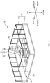
- FIG. 1 is a schematic perspective view of the dog toilet 10.
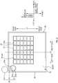
- FIG. 2 is a plan view of the dog toilet 10 viewed from above.
- FIG. 3 is a sectional view illustrating an example of a configuration of a bottom portion 20.
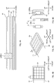
- FIG. 4A is a sectional view illustrating an arrangement of individual electrodes (a positive electrode 41 and a negative electrode 42) in the bottom portion 20.
- FIG. 4B is a plan view of a portion around a grate 24 viewed from above
- FIG. 4C is a perspective view of FIG. 4B
- FIG. 4D is a sectional view. Note that, in FIG.
- FIG. 5 is a block diagram illustrating configurations of a urination detection sensor 40 and a feeder unit 50.
- the dog toilet 10 is a toilet capable of being used for toilet-training a dog and is placed on the floor or the like for use.
- front-rear direction "left-right direction”, and "up-down direction”, which denote three directions perpendicular to one another, are defined as illustrated in FIG. 1 .
- the up-down direction is the vertical direction.
- a placement surface (a bottom surface of a bottom-portion main body 21) side is denoted as "lower side”, and the opposite side is denoted as "upper side”.
- the front-rear direction and the left-right direction denote directions of a horizontal plane (horizontal direction) .
- a central position in the front-rear direction is denoted as a center position C1.
- a side where an access opening 33 is provided relative to the center position C1 is denoted as "front side”, and the opposite side is denoted as “rear side”.
- a central position in the left-right direction is denoted as a center position C2.
- a side where the access opening 33 is provided relative to the center position C2 is denoted as "left side”, and the opposite side is denoted as "right side”.
- the dog toilet 10 includes the bottom portion 20, a wall portion 30, the urination detection sensor 40, and the feeder unit 50.
- the bottom portion 20 has a rectangular shape in plan view, and respective sides of the bottom portion 20 extend in the front-rear direction and the left-right direction.
- the bottom portion 20 includes the bottom-portion main body 21 (corresponding to a receptacle), a protruding portion 22, an absorption sheet 23 (corresponding to an absorbent member), the grate 24 (corresponding to an insulating member and a liquid-permeable layer), and a cover 25.
- the bottom-portion main body 21 is the lowest portion (base) of the bottom portion 20 and is a portion that constitutes a toilet structure.
- An area surrounded by the protruding portion 22 in the bottom-portion main body 21 is an area where a dog excretes. In the following description, this area is also referred to as an excretion area.
- the protruding portion 22 is a portion that protrudes upward from the bottom-portion main body 21 and is provided so as to surround the absorption sheet 23.
- the bottom-portion main body 21 is provided with the protruding portion 22 in this manner, and the absorption sheet 23 is arranged inside the protruding portion 22. Consequently, the absorption sheet 23 is less likely to be displaced (the absorption sheet 23 is less likely to be moved) even if the dog walks around, for example.
- the absorption sheet 23 is a liquid-absorbent sheet member that absorbs urine or the like excreted by an animal (herein, a dog), and the absorption sheet 23 includes a liquid absorbent material (corresponding to an absorbent body) such as pulp fiber or superabsorbent polymer.
- the absorption sheet 23 contains deodorant microcapsules and an antibacterial agent, masking the smell of absorbed urine and suppressing the propagation of bacteria from occurring.
- the absorption sheet 23 is arranged in the excretion area (the area surrounded by the protruding portion 22 in the bottom-portion main body 21). As a result of the absorption sheet 23 being arranged in the excretion area in this manner, urine is absorbed by the absorption sheet 23. This makes it possible to suppress erroneous operation of the urination detection sensor 40 and a feeder 52 due to dispersal of urine caused by vibration that occurs when the dog moves around wildly, for example.
- the absorption sheet 23 (as well as the grate 24) is arranged to be lopsided with respect to the center position C1 in the front-rear direction. Specifically, the absorption sheet 23 is arranged such that the area of a portion on the rear side with respect to the center position C1 is larger than the area of a portion on the front side with respect to the center position C1 (see FIG. 2 ). This is because the possibility of the dog approaching a feeding plate 51 is high because of the smell of food remaining in the feeding plate 51 when the dog enters the dog toilet 10, and therefore the possibility of the dog urinating on the rear side relative to the center position C1 is high. Thus, making the area of the rear-side (feeding-plate-51-side) portion larger than the area of the front-side (access-opening-33-side) portion relative to the center position C1 makes it possible for the absorption sheet 23 to be arranged efficiently.
- the grate 24 is arranged so as to cover the absorption sheet 23 (that is, in the excretion area).
- the grate 24 has the plurality of apertures 24a penetrating in the up-down direction and enables urine or the like excreted by the dog to pass through the apertures 24a from the upper side to the lower side (toward the absorption sheet 23) in the up-down direction. That is, the grate 24 corresponds to a liquid-permeable layer.
- the grate 24 in the present embodiment is formed into a rectangular grating shape, and the apertures 24a each have a rectangular shape in plan view. However, the configuration is not limited to this, and a grate having circular or hexagonal apertures may be used.
- the positive electrode 41 and the negative electrode 42 of the urination detection sensor 40 are arranged on the grate 24.
- an insulator particularly, a non-liquid-absorbent insulator that does not absorb liquid (for example, polypropylene, silicone, or the like) is used.
- a non-liquid-absorbent insulator that does not absorb liquid
- an absorbent insulator for example, sponge
- the insulator absorbs urine.
- the absorbed urine causes the positive electrode 41 and the negative electrode 42 to continue conducting electricity, which hinders accurate determination.
- That the grate 24 is composed of a non-liquid-absorbent insulator makes it less likely for the grate 24 to hold urine. This makes it possible to prevent a first electrode and a second electrode from continuing conducting electricity.
- a hydrophobic material having a surface that increases surface tension is preferably used.
- the cover 25 is attached above the bottom-portion main body 21 and covers the bottom-portion main body 21 and the protruding portion 22.
- the cover 25 has an opening in a portion corresponding to the position where the absorption sheet 23 is arranged (the excretion area). Consequently, the cover 25 constitutes an upper surface of the bottom portion 20 except for the excretion area.
- the grate 24 is suspended on the cover 25 in such a manner to move in the up-down direction.
- the wall portion 30 is provided so as to surround the four sides of the bottom portion 20 (in the front-rear direction and the left-right direction). In the following description, an inner side of the wall portion 30 is also referred to as inside the toilet.
- the wall portion 30 in the present embodiment includes a plate wall 31, a fence 32, and the access opening 33.
- the plate wall 31 is a plate-shaped wall that is continuous and is erected on the bottom portion 20.
- the plate wall 31 illustrated in FIG. 3 has side faces that are perpendicular to the horizontal plane and that have a constant thickness irrespective of the position in the up-down direction.
- the configuration of the plate wall 31 is not limited to this.
- the plate wall 31 may be an inclined surface having a thickness that decreases from the lower side to the upper side in the up-down direction.
- the plate wall 31 may be an inclined surface having a thickness that increases from the lower side to the upper side in the up-down direction.
- the fence 32 is a mesh-like barrier having voids and is provided above the plate wall 31.
- the wall portion 30 of the dog toilet 10 has a combined configuration of the plate wall 31 and the fence 32.
- the plate wall 31 constitutes the lower portion of the wall portion 30, and this ensures that food or urine of the dog are less likely to spill to an area outside the toilet.
- the fence 32 constitutes the upper portion of the wall portion 30, and this enables the dog to have good visibility, making it possible for the dog to urinate in the toilet with peace.
- a feeding tube 53 is easily drawn through the wall portion 30 to the inner side of the wall portion 30. Note that as materials of the plate wall 31 and the fence 32, any material, such as metal, plastic, or wood, may be used.
- the access opening 33 is a portion where the dog enters and exits the toilet (the inner side of the wall portion 30) and is formed at the left side of a portion (front-side portion) of the wall portion 30 that demarcates the front side of the bottom portion 20. That is, the access opening 33 is provided on the front side relative to the center position C1 in the front-rear direction and on the left side relative to the center position C2 in the left-right direction.
- the access opening 33 in the present embodiment is formed by making an opening at the above-described portion of the wall portion 30 (the plate wall 31 and the fence 32) surrounding the bottom portion 20 (making the above-described portion discontinuous).
- the urination detection sensor 40 is a sensor that detects whether there is urination by a dog (specifically, the presence of liquid) .
- the urination detection sensor 40 includes the positive electrode 41 (corresponding to a first electrode), the negative electrode 42 (corresponding to a second electrode), and a liquid sensor 43.
- the positive electrode 41 is arranged on (the upper surface of) the grate 24.
- a material of the positive electrode 41 a material having high conductivity (for example, copper or rust-resistant stainless steel) is preferable.
- the negative electrode 42 is also formed of a material having high conductivity, similarly to the positive electrode 41, and is arranged under (on the lower surface of) the grate 24.
- the positive electrode 41 and the negative electrode 42 are provided on the grate 24 that covers the absorption sheet 23. This make urine be quickly absorbed by the absorption sheet 23, making it possible to reduce the amount of urine that remains on the electrodes. Consequently, it is possible to correctly detect the urination timing.
- the grate 24 and the individual electrodes (the positive electrode 41 and the negative electrode 42), and the negative electrode 42 and the absorption sheet 23 are illustrated as spaced apart from each other. However, they are actually in contact with each other.
- urine adhered to the negative electrode 42 can be absorbed by the absorption sheet 23. This can suppress, for example, the occurrence of the smell of urine.
- the grate 24 is suspended on the cover 25 to be vertically movable as described above, the negative electrode 42 is vertically movable together with the grate 24 even if the absorption sheet 23 expands due to absorbing urine.
- the positive electrode 41 is divided into a plurality of branches on the grate 24, and the plurality of branches are linearly arranged extending along the front-rear direction with spaces therebetween in the left-right direction to be parallel to one another.
- the negative electrode 42 is also divided into a plurality of branches on the grate 24, and the plurality of branches are linearly arranged extending along the front-rear direction with spaces therebetween in the left-right direction to be parallel to one another (to form pairs with the positive electrode 41).
- a plurality of pairs of the positive electrode 41 and the negative electrode 42 are arranged side-by-side in the horizontal direction (the left-right direction).
- the electrodes can be arranged densely, making it possible to increase the accuracy of the urination detection sensor 40.
- the positive electrode 41 and the negative electrode 42 forming a pair are spaced apart in the up-down direction and superpose in terms of position in the horizontal direction (the left-right direction herein).
- the positive electrode 41 is arranged on the grate 24 and the negative electrode 42 is arranged under the grate 24 in the present embodiment, the arrangement may be reversed. That is, the negative electrode 42 may be arranged on the grate 24 and the positive electrode 41 may be arranged under the grate 24.
- each of the positive electrode 41 and the negative electrode 42 that constitute a pair is linearly arranged along the front-rear direction in the present embodiment, the arrangement is not limited to this.
- each of the positive electrode 41 and the negative electrode 42 may be arranged in the left-right direction.
- each of the positive electrode 41 and the negative electrode 42 may be arranged to be bent in a zigzag shape on the horizontal plane in accordance with the shape of the grate 24.
- a distance d between the electrodes that are adjacent to each other in the horizontal direction may be arbitrary. However, since urine needs at least to be directly in contact with the electrodes, the distance is desirably 5 cm or less. In addition, if the distance is too short, it is difficult to remove feces soiling. Therefore, the distance is desirably 1 cm or greater.
- a width W2 of the grate 24 illustrated in FIG. 4D is greater than a width W1 of the positive electrode 41 and the negative electrode 42. This is because, if the width W2 of the grate 24 is less than the width W1 of the positive electrode 41 and the negative electrode 42, there is a risk that urine remains on a side wall of the grate 24 owing to surface tension of the urine and the conducting state continues, and decreases the accuracy of the urination detection sensor 40.
- the width W2 of the grate 24 is set greater than the width W1 of the positive electrode 41 and the negative electrode 42.
- the liquid sensor 43 amplifies an electric signal (voltage) when the positive electrode 41 and the negative electrode 42 conduct electricity, and outputs the amplified signal to a microcomputer 55.
- a method for controlling the liquid sensor 43 involves analog control using an analog voltage value.
- the control method is not limited to this, and digital control using H (high)/L (low) digital signals may be used.
- the feeder unit 50 includes the feeding plate 51, the feeder 52, the feeding tube 53, a power supply 54, the microcomputer 55, and a relay circuit 56.
- the feeding plate 51 is a container in which dog food is held.
- the feeding plate 51 includes a bottom wall 51a having a circular shape in plan view, and a peripheral side wall 51b that is erected upward on the periphery of the bottom wall 51a.
- a feeding port 53a (described later) of the feeding tube 53 is prevented from rolling out onto the excretion area.
- food is stored in a food container 100 (described later) of the feeder 52 and is supplied to the feeding plate 51 from the feeder 52 through the feeding tube 53.
- the feeding plate 51 (in other words, the feeding port 53a) is arranged in a corner portion (that is, a corner portion on a left rear side in the wall portion 30), and this corner portion is formed by a portion of the wall portion 30 on the rear side in the left-right direction and a portion of the wall portion 30 on the left side in the left-right direction. This can ensure a wide space (excretion area) in the toilet.
- the feeder 52 is an electrically powered apparatus that automatically supplies food on the basis of a detection result of the urination detection sensor 40.
- the feeding tube 53 is attached to the feeder 52. Note that the feeder 52 is arranged outside the wall portion 30, and that the feeding tube 53 attached to the feeder 52 is drawn to the inner side of the wall portion 30 through the fence 32. The configuration of the feeder 52 will be described later.
- the feeding tube 53 is a hollow tubular member (for example, a tube) for supplying food ejected from the feeder 52 to the feeding plate 51, and the feeding tube 53 has the feeding port 53a.
- the feeding port 53a is an outlet of the feeding tube 53 and is arranged above the feeding plate 51 in the toilet. That is, the feeding port 53a is arranged on the rear side relative to the center position C1 in the front-rear direction.
- the feeding plate 51 is arranged on the rear side in the front-rear direction and the access opening 33 is provided in the wall portion 30 on the front side in the front-rear direction. If the positions of the feeding port 53a and the access opening 33 are close to each other, the dog may discharge residual urine in an area outside the toilet while eating food.
- the positions of the feeding port 53a and the access opening 33 are apart from each other. This makes it possible for the dog who is eating food to stay in the toilet after urination, making it possible to prevent an area outside the toilet from being soiled with urine.
- the power supply 54 supplies electric power to each of the components (the feeder 52, the microcomputer 55, and the relay circuit 56) of the feeder unit 50.
- the output of the urination detection sensor 40 (the liquid sensor 43) is input to the microcomputer 55.
- the microcomputer 55 performs control described below, in accordance with a change in voltage of the urination detection sensor 40. That is, when the voltage falls below a predetermined voltage (because the positive electrode 41 and the negative electrode 42 stop conducting electricity) after the voltage rises (because the positive electrode 41 and the negative electrode 42 conduct electricity), the microcomputer 55 causes the relay circuit 56 to operate.
- the relay circuit 56 operates (is active) for a certain period according to controlling of the time in seconds, and thereby the relay circuit 56 causes the feeder 52 to operate (specifically, a motor 120 described later is driven to rotate a rotational body 111). Consequently, food is supplied from the feeder 52.
- FIG. 6A is a schematic sectional view illustrating an example of a configuration of the feeder 52
- FIG. 6B is a top view of a scale 110 illustrated in FIG. 6A .
- the feeder 52 includes the food container 100, the scale 110, and the motor 120.
- the food container 100 is a hollow cylindrical member provided in an upper portion of the feeder 52 and stores dog food therein.
- a through hole 100a is provided in a bottom portion of the food container 100, so that food drops from the through hole 100a due to its weight.
- the scale 110 is a weigh scale arranged under the food container 100 and includes the rotational body 111 and a periphery wall portion 112.
- the rotational body 111 includes a bottom portion 111a and a plurality of partition plates 111b.
- the bottom portion 111a is a plate-shaped member having a circular shape in plan view. Note that an upper surface of the bottom portion 111a is an inclined surface where the height of an outer portion is lower than the height of the center position.
- the partition plates 111b are provided on the upper surface of the bottom portion 111a.
- the plurality of partition plates 111b are provided radially at an equal interval, with respect to an axis located at the center of the bottom portion 111a. Consequently, the partition plates 111b partition a space above the bottom portion 111a into a plurality of spaces.
- the periphery wall portion 112 is provided to surround the outer side of the rotational body 111.
- An opening 112a is formed in the periphery wall portion 112 at a position corresponding to one of partitioned portions formed by the partition plates 111b.
- the feeding tube 53 is arranged outside the opening 112a. Food ejected from the opening 112a is supplied to the feeding plate 51 through the feeding tube 53.
- the motor 120 is driven in accordance with the output of the relay circuit 56, rotating the rotational body 111 of the scale 110. That is, the motor 120 rotates the rotational body 111 in a circumferential direction around the axis located at the center of the rotational body 111.
- the positive electrode 41 and the negative electrode 42 of the urination detection sensor 40 conduct electricity through the urine, which is an electrical conductor.
- the conducted voltage is amplified by the liquid sensor 43 and is sent to the microcomputer 55.
- the microcomputer 55 causes the relay circuit 56 to operate for a certain period. Consequently, the motor 120 of the feeder 52 is driven to rotate the rotational body 111 of the scale 110 by a certain amount.
- the absorption sheet 23 and the grate 24 are arranged above the bottom-portion main body 21 in the dog toilet 10 according to the present embodiment, the absorption sheet 23 and the grate 24 may be omitted. In this case, however, there is a risk that the urination detection sensor 40 fails to correctly detect urination, causing the feeder 52 to erroneously operate.
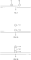
- FIG. 7 is a conceptual diagram illustrating a comparative example of the arrangement of the electrodes.
- the positive electrode 41 and the negative electrode 42 are arranged on the bottom-portion main body 21 to be in contact with the bottom-portion main body 21. Also in this case, the positive electrode 41 and the negative electrode 42 conduct electricity through urine when a dog urinates. In this comparative example, however, the conducting state continues until urine dries naturally. For this reason, the time at which urination completes cannot be determined, and there is a risk that the feeder 52 continues operating. Further, as a result of continuation of the conducting state, there is a risk that detection of the second and subsequent urinations fail.
- the positive electrode 41 and the negative electrode 42 are spaced apart from the bottom-portion main body 21 in the dog toilet 10 according to the present embodiment. This makes it possible to suppress the occurrence of erroneous operation of the feeder 52.
- FIG. 8A is a conceptual diagram illustrating a first modification of the arrangement of the electrodes.
- FIG. 8B is a conceptual diagram illustrating an improved example of FIG. 8A .
- the positive electrode 41 and the negative electrode 42 are arranged above the bottom-portion main body 21 such that the positive electrode 41 and the negative electrode 42 are adjacent to each other in the up-down direction (vertical direction) and overlap in terms of position in the horizontal direction.
- the negative electrode 42 is in contact with the bottom-portion main body 21, and the positive electrode 41 is provided above the negative electrode 42.
- the positive electrode 41 is spaced apart from the bottom-portion main body 21.
- the positions of the positive electrode 41 and the negative electrode 42 in the horizontal direction are completely coincident in FIG. 8A , the positions may be at least partially coincident (may be slightly shifted from each other in the horizontal direction).
- an insulating member 24' is arranged between the positive electrode 41 and the negative electrode 42.
- the insulating member 24' is a non-absorbent insulating member composed of the same material as the grate 24.
- the positive electrode 41 and the negative electrode 42 forming a pair are disposed vertically adjacently. However, the positive electrode 41 and the negative electrode 42 forming a pair are disposed horizontally adjacently in the second modification.
- FIG. 9A is a conceptual diagram illustrating a second modification of the arrangement of the electrodes.
- FIG. 9B is a conceptual diagram illustrating an improved example of FIG. 9A .
- neither the absorption sheet 23 nor the grate 24 is provided as in the comparative example ( FIG. 7 ).
- the positive electrode 41 and the negative electrode 42 are arranged adjacently in the horizontal direction. Both the positive electrode 41 and the negative electrode 42 are spaced apart from the bottom-portion main body 21. Also in the second embodiment, it is possible to suppress the occurrence of erroneous operation, compared with the comparative example ( FIG. 7 ). However, there is a risk that the positive electrode 41 and the negative electrode 42 continue conducting electricity due to urine dripping from the positive electrode 41, or urine accumulated in the bottom-portion main body 21, or urine dripping from the negative electrode 42.
- the insulating member 24' is arranged between the positive electrode 41 and the bottom-portion main body 21 and between the negative electrode 42 and the bottom-portion main body 21.
- the insulating member 24' is a non-absorbent insulator similar to the grate 24.
- the insulating member 24' is arranged both between the positive electrode 41 and the bottom-portion main body 21 and between the negative electrode 42 and the bottom-portion main body 21 in this improved example.
- the insulating member 24' may be arranged only either between the positive electrode 41 and the bottom-portion main body 21 or between the negative electrode 42 and the bottom-portion main body 21.
- the electrode for which the insulating member 24' is not arranged may be in contact with the bottom-portion main body 21.
- the positive electrode 41 and the negative electrode 42 can be prevented from continuing conducting electricity, and consequently erroneous operation of the feeder 52 can be suppressed from occurring.
- the absorption sheet 23 may be provided below the positive electrode 41 and the negative electrode 42 in FIG. 9B .
- both the positive electrode 41 and the negative electrode 42 may be in contact with the absorption sheet 23. In this way, urine adhered to each of the electrodes can be absorbed by the absorption sheet 23, and the occurrence of the smell of urine or the like can be suppressed.
- FIG. 10 is an explanatory diagram illustrating an example of an arrangement in the case where the plurality of positive electrodes 41 and the plurality of negative electrodes 42 are arranged side-by-side horizontally.
- the positive electrode 41 and the negative electrode 42 forming a pair are arranged side-by-side (spaced apart from each other) in the up-down direction in FIG. 4C .
- the positive electrode 41 and the negative electrode 42 forming a pair are arranged side-by-side in the horizontal direction (in the left-right direction herein) in FIG. 10 .
- a plurality of pairs of the positive electrode 41 and the negative electrode 42 are arranged side-by-side with spaces therebetween in the horizontal direction (the left-right direction).
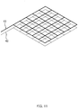
- FIG. 11 is a conceptual diagram illustrating a third modification of the arrangement of the electrodes.
- the positive electrode 41 and the negative electrode 42 are denoted by solid lines of different thicknesses.
- both the positive electrode 41 and the negative electrode 42 are configured to have a grating shape. That is, the positive electrode 41 includes portions intersecting with each other and the negative electrode 42 includes portions intersecting with each other.
- the positive electrode 41 and the negative electrode 42 having a grating shape are arranged to be spaced apart from each other in the up-down direction. Consequently, the electrodes can be arranged more densely, and the accuracy of the urination detection sensor 40 can be increased.
- the wall portion 30 is constituted by the plate wall 31, and the fence 32.
- the present invention is not limited thereto. Any configuration of the wall portion 30 may be employed. Also, it is acceptable that the wall portion 30 (including the access opening 33) is not provided.
- food is supplied to the feeding plate 51.
- the present invention is not limited thereto.
- food may be scattered on the bottom portion 20.
- the present invention is not limited thereto.
- the feeder 52 is arranged within the wall portion 30.
- the feeder 52 is provided as a device that operates on the basis of a detection result of the urination detection sensor 40.
- the device is not limited to this, and a device (operating device) that generates a stimulus favorable to a dog may be used.
- a device that generates smell, sound, light, or the like may be provided, and the device may be caused to operate on the basis of a detection result of the urination detection sensor.
Landscapes
- Life Sciences & Earth Sciences (AREA)
- Environmental Sciences (AREA)
- Animal Husbandry (AREA)
- Biodiversity & Conservation Biology (AREA)
- Zoology (AREA)
- Birds (AREA)
- Biophysics (AREA)
- Orthopedics, Nursing, And Contraception (AREA)
- Housing For Livestock And Birds (AREA)
- Absorbent Articles And Supports Therefor (AREA)
Abstract

Description
- The present invention relates to a dog toilet.
- Conventionally, animal toilets used by animals such as pets (for example, dogs) are known. As animal toilets, there are also known toilets that give a stimulus (such as food, sound, or smell) when animals excrete in the toilets to train (toilet-train) the animals to spontaneously excrete in the toilets. For example, a toilet described in Patent Literature 1 includes: a urination detection sensor provided in a bottom portion; and a feeder (operating device) that operates on the basis of a detection result of the urination detection sensor. When the urination detection sensor detects excretion by an animal, the feeder operates to supply food.
- [Patent Literature 1] Japanese Patent Application Publication No.
2009-45053 - However, in the toilet described above, there is a risk that the conducting state of the urination detection sensor continues after urination and causes the feeder to operate erroneously. Specifically, when the urination detection sensor conducts in response to the first urination, the conducting state continues until urine dries naturally. Consequently, there is a risk that the time at which urination completes cannot be determined, causing the feeder to continue operating. Further, there is a risk that continuation of the conducting state causes to fail detection of the second and subsequent urinations.
- The present invention was achieved in light of conventional problems such as that described above, and an aspect of the present invention is to provide a dog toilet capable of preventing erroneous operation of an operating device.
- A main aspect of the present invention for achieving the above-described aspect is as follow.
- A dog toilet including:
- a receptacle in which a dog urinates;
- a urination detection sensor including a first electrode and a second electrode; and
- an operating device configured to operate based on a conducting state of the first electrode and the second electrode of the urination detection sensor,
- at least either one of the first electrode and the second electrode being spaced apart from the receptacle.
- Features of the present invention other than the above will become clear by reading the description of the present specification with reference to the accompanying drawings.
- According to the present invention, it is possible to provide a dog toilet capable of preventing erroneous operation of an operating device.
-
- [
FIG. 1] FIG. 1 is a schematic perspective view of adog toilet 10. - [
FIG. 2] FIG. 2 is a plan view of thedog toilet 10 viewed from above. - [
FIG. 3] FIG. 3 is a sectional view illustrating a configuration of abottom portion 20. - [
FIG. 4] FIG. 4A is a sectional view illustrating an arrangement of individual electrodes (apositive electrode 41 and a negative electrode 42) in thebottom portion 20.FIG. 4B is a plan view of a portion around agrate 24 viewed from above.FIG. 4C is a perspective view ofFIG. 4B. FIG. 4D is a sectional view. - [
FIG. 5] FIG. 5 is a block diagram illustrating configurations of aurination detection sensor 40 and afeeder unit 50. - [
FIG. 6] FIG. 6A is a schematic sectional view illustrating a configuration of afeeder 52.FIG. 6B is a top view of ascale 110 illustrated inFIG. 6A . - [
FIG. 7] FIG. 7 is a conceptual diagram illustrating a comparative example of the arrangement of the electrodes. - [
FIG. 8] FIG. 8A is a conceptual diagram illustrating a first modification of the arrangement of the electrodes, andFIG. 8B is a conceptual diagram illustrating an improved example ofFIG. 8A . - [
FIG. 9] FIG. 9A is a conceptual diagram illustrating a second modification of the arrangement of the electrodes, andFIG. 9B is a conceptual diagram illustrating an improved example ofFIG. 9A . - [
FIG. 10] FIG. 10 is an explanatory diagram illustrating an example of an arrangement in the case where a plurality ofpositive electrodes 41 and a plurality ofnegative electrodes 42 are arranged horizontally adjacently. - [
FIG. 11] FIG. 11 is a conceptual diagram illustrating a third modification of the arrangement of the electrodes. - At least the following matters will become clear with the description of this specification and the attached drawings.
- A dog toilet including:
- a receptacle in which a dog urinates;
- a urination detection sensor including a first electrode and a second electrode; and
- an operating device configured to operate based on a conducting state of the first electrode and the second electrode of the urination detection sensor,
- at least either one of the first electrode and the second electrode being spaced apart from the receptacle.
- With such a dog toilet, it becomes less likely for electricity to conduct except during the time of urination, making it possible to suppress the occurrence of erroneous operation of the operating device.
- In such a dog toilet, it is acceptable that
an insulating member is arranged between the receptacle and at least either one of the first electrode and the second electrode. - With such a dog toilet, conduction of electricity between the first electrode and the second electrode through urine in the receptacle does not occur, making it possible to suppress the occurrence of erroneous operation of the operating device.
- In such a dog toilet, it is acceptable that
the insulating member is arranged between the first electrode and the second electrode. - With such a dog toilet, it is possible to prevent the first electrode and the second electrode from continuing conducting electricity through urine, making it possible to suppress the occurrence of erroneous operation of the operating device.
- In such a dog toilet, it is acceptable that
a non-absorbent material is used as the insulating member. - With such a dog toilet, urine is not held by the insulating member, making it possible to suppress the occurrence of erroneous operation of the operating device.
- In such a dog toilet, it is acceptable that
the first electrode and the second electrode are both spaced apart from the receptacle, and
an absorbent member is arranged below the first electrode and the second electrode,
the absorbent member including a liquid-absorbent, absorbent body. - With such a dog toilet, since urine is absorbed by the absorbent member, it is possible to suppress the occurrence of erroneous operation caused, for example, by splashing of urine held in the receptacle due to vibration that occurs when a dog moves around wildly.
- In such a dog toilet, it is acceptable that
at least either one of the first electrode and the second electrode is in contact with the absorbent member. - With such a dog toilet, it is possible for the absorbent member to absorb urine adhered to the electrodes. This can suppress the smell of urine, for example.
- In such a dog toilet, it is acceptable that
the first electrode and the second electrode are arranged on a liquid-permeable layer that covers the absorbent member. - With such a dog toilet, urine is quickly absorbed by the absorbent member. This makes it possible to reduce the amount of urine remaining on the electrodes. Consequently, it is possible to correctly detect the urination timing.
- In such a dog toilet, it is acceptable that
the first electrode and the second electrode are spaced apart from each other in a vertical direction, and
the first electrode and the second electrode at least partially overlap in a horizontal direction. - With such a dog toilet, the first electrode and the second electrode can certainly conduct electricity through urine that moves downward (flows downward) in the vertical direction.
- In such a dog toilet, it is acceptable that
an insulating member is arranged between the first electrode and the second electrode, and
a width of the insulating member is greater than a width of the first electrode and greater than a width of the second electrode. - With such a dog toilet, urine covering a portion between the electrodes is more likely to undergo flued thread breakup, making it possible to increase the accuracy of the urination detection sensor.
- In such a dog toilet, it is acceptable that
a plurality of pairs of the first electrode and the second electrode are arranged side-by-side in a horizontal direction. - With such a dog toilet, the electrodes can be arranged densely, making it possible to increase the accuracy of the urination detection sensor.
- In such a dog toilet, it is acceptable that
the first electrode and the second electrode are spaced apart from each other in a vertical direction,
the first electrode includes portions intersecting with each other, and
the second electrode includes portions intersecting with each other. - With such a dog toilet, the electrodes can be arranged more densely, making it possible to increase the accuracy of the urination detection sensor.
- A
dog toilet 10 will be described as an example of a dog toilet according to the present embodiment.FIG. 1 is a schematic perspective view of thedog toilet 10.FIG. 2 is a plan view of thedog toilet 10 viewed from above. In addition,FIG. 3 is a sectional view illustrating an example of a configuration of abottom portion 20. Further,FIG. 4A is a sectional view illustrating an arrangement of individual electrodes (apositive electrode 41 and a negative electrode 42) in thebottom portion 20. In addition,FIG. 4B is a plan view of a portion around agrate 24 viewed from above,FIG. 4C is a perspective view ofFIG. 4B, and FIG. 4D is a sectional view. Note that, inFIG. 4C ,apertures 24a of thegrate 24 are omitted to clarify the arrangement of the individual electrodes, and viewable portions of the electrodes are denoted by solid lines and hidden portions of the electrodes are denoted by broken lines. Further,FIG. 5 is a block diagram illustrating configurations of aurination detection sensor 40 and afeeder unit 50. - The
dog toilet 10 is a toilet capable of being used for toilet-training a dog and is placed on the floor or the like for use. In the following description, "front-rear direction", "left-right direction", and "up-down direction", which denote three directions perpendicular to one another, are defined as illustrated inFIG. 1 . The up-down direction is the vertical direction. A placement surface (a bottom surface of a bottom-portion main body 21) side is denoted as "lower side", and the opposite side is denoted as "upper side". In addition, the front-rear direction and the left-right direction denote directions of a horizontal plane (horizontal direction) . As illustrated inFIG. 2 , a central position in the front-rear direction is denoted as a center position C1. A side where anaccess opening 33 is provided relative to the center position C1 is denoted as "front side", and the opposite side is denoted as "rear side". In addition, a central position in the left-right direction is denoted as a center position C2. A side where the access opening 33 is provided relative to the center position C2 is denoted as "left side", and the opposite side is denoted as "right side". - The
dog toilet 10 includes thebottom portion 20, awall portion 30, theurination detection sensor 40, and thefeeder unit 50. - As illustrated in
FIG. 1 andFIG. 2 , thebottom portion 20 has a rectangular shape in plan view, and respective sides of thebottom portion 20 extend in the front-rear direction and the left-right direction. In addition, as illustrated inFIG. 3 , thebottom portion 20 includes the bottom-portion main body 21 (corresponding to a receptacle), a protrudingportion 22, an absorption sheet 23 (corresponding to an absorbent member), the grate 24 (corresponding to an insulating member and a liquid-permeable layer), and acover 25. - The bottom-portion
main body 21 is the lowest portion (base) of thebottom portion 20 and is a portion that constitutes a toilet structure. An area surrounded by the protrudingportion 22 in the bottom-portion main body 21 (in other words, an area where theabsorption sheet 23 is arranged) is an area where a dog excretes. In the following description, this area is also referred to as an excretion area. - The protruding
portion 22 is a portion that protrudes upward from the bottom-portionmain body 21 and is provided so as to surround theabsorption sheet 23. The bottom-portionmain body 21 is provided with the protrudingportion 22 in this manner, and theabsorption sheet 23 is arranged inside the protrudingportion 22. Consequently, theabsorption sheet 23 is less likely to be displaced (theabsorption sheet 23 is less likely to be moved) even if the dog walks around, for example. - The
absorption sheet 23 is a liquid-absorbent sheet member that absorbs urine or the like excreted by an animal (herein, a dog), and theabsorption sheet 23 includes a liquid absorbent material (corresponding to an absorbent body) such as pulp fiber or superabsorbent polymer. In addition, in the present embodiment, theabsorption sheet 23 contains deodorant microcapsules and an antibacterial agent, masking the smell of absorbed urine and suppressing the propagation of bacteria from occurring. Theabsorption sheet 23 is arranged in the excretion area (the area surrounded by the protrudingportion 22 in the bottom-portion main body 21). As a result of theabsorption sheet 23 being arranged in the excretion area in this manner, urine is absorbed by theabsorption sheet 23. This makes it possible to suppress erroneous operation of theurination detection sensor 40 and afeeder 52 due to dispersal of urine caused by vibration that occurs when the dog moves around wildly, for example. - Note that, in the present embodiment, the absorption sheet 23 (as well as the grate 24) is arranged to be lopsided with respect to the center position C1 in the front-rear direction. Specifically, the
absorption sheet 23 is arranged such that the area of a portion on the rear side with respect to the center position C1 is larger than the area of a portion on the front side with respect to the center position C1 (seeFIG. 2 ). This is because the possibility of the dog approaching afeeding plate 51 is high because of the smell of food remaining in thefeeding plate 51 when the dog enters thedog toilet 10, and therefore the possibility of the dog urinating on the rear side relative to the center position C1 is high. Thus, making the area of the rear-side (feeding-plate-51-side) portion larger than the area of the front-side (access-opening-33-side) portion relative to the center position C1 makes it possible for theabsorption sheet 23 to be arranged efficiently. - The
grate 24 is arranged so as to cover the absorption sheet 23 (that is, in the excretion area). Thegrate 24 has the plurality ofapertures 24a penetrating in the up-down direction and enables urine or the like excreted by the dog to pass through theapertures 24a from the upper side to the lower side (toward the absorption sheet 23) in the up-down direction. That is, thegrate 24 corresponds to a liquid-permeable layer. Thegrate 24 in the present embodiment is formed into a rectangular grating shape, and theapertures 24a each have a rectangular shape in plan view. However, the configuration is not limited to this, and a grate having circular or hexagonal apertures may be used. As described later, thepositive electrode 41 and thenegative electrode 42 of theurination detection sensor 40 are arranged on thegrate 24. - As a material of the
grate 24, an insulator, particularly, a non-liquid-absorbent insulator that does not absorb liquid (for example, polypropylene, silicone, or the like) is used. This is because, if an absorbent insulator (for example, sponge) is used, the insulator absorbs urine. The absorbed urine causes thepositive electrode 41 and thenegative electrode 42 to continue conducting electricity, which hinders accurate determination. That thegrate 24 is composed of a non-liquid-absorbent insulator makes it less likely for thegrate 24 to hold urine. This makes it possible to prevent a first electrode and a second electrode from continuing conducting electricity. In addition, as the material of thegrate 24, a hydrophobic material having a surface that increases surface tension is preferably used. - The
cover 25 is attached above the bottom-portionmain body 21 and covers the bottom-portionmain body 21 and the protrudingportion 22. In addition, thecover 25 has an opening in a portion corresponding to the position where theabsorption sheet 23 is arranged (the excretion area). Consequently, thecover 25 constitutes an upper surface of thebottom portion 20 except for the excretion area. In addition, thegrate 24 is suspended on thecover 25 in such a manner to move in the up-down direction. - The
wall portion 30 is provided so as to surround the four sides of the bottom portion 20 (in the front-rear direction and the left-right direction). In the following description, an inner side of thewall portion 30 is also referred to as inside the toilet. Thewall portion 30 in the present embodiment includes aplate wall 31, afence 32, and theaccess opening 33. - The
plate wall 31 is a plate-shaped wall that is continuous and is erected on thebottom portion 20. Theplate wall 31 illustrated inFIG. 3 has side faces that are perpendicular to the horizontal plane and that have a constant thickness irrespective of the position in the up-down direction. However, the configuration of theplate wall 31 is not limited to this. For example, theplate wall 31 may be an inclined surface having a thickness that decreases from the lower side to the upper side in the up-down direction. Conversely, theplate wall 31 may be an inclined surface having a thickness that increases from the lower side to the upper side in the up-down direction. - The
fence 32 is a mesh-like barrier having voids and is provided above theplate wall 31. - Thus, the
wall portion 30 of thedog toilet 10 according to the present embodiment has a combined configuration of theplate wall 31 and thefence 32. Theplate wall 31 constitutes the lower portion of thewall portion 30, and this ensures that food or urine of the dog are less likely to spill to an area outside the toilet. In addition, thefence 32 constitutes the upper portion of thewall portion 30, and this enables the dog to have good visibility, making it possible for the dog to urinate in the toilet with peace. In addition, a feedingtube 53 is easily drawn through thewall portion 30 to the inner side of thewall portion 30. Note that as materials of theplate wall 31 and thefence 32, any material, such as metal, plastic, or wood, may be used. - The
access opening 33 is a portion where the dog enters and exits the toilet (the inner side of the wall portion 30) and is formed at the left side of a portion (front-side portion) of thewall portion 30 that demarcates the front side of thebottom portion 20. That is, the access opening 33 is provided on the front side relative to the center position C1 in the front-rear direction and on the left side relative to the center position C2 in the left-right direction. The access opening 33 in the present embodiment is formed by making an opening at the above-described portion of the wall portion 30 (theplate wall 31 and the fence 32) surrounding the bottom portion 20 (making the above-described portion discontinuous). - The
urination detection sensor 40 is a sensor that detects whether there is urination by a dog (specifically, the presence of liquid) . Theurination detection sensor 40 includes the positive electrode 41 (corresponding to a first electrode), the negative electrode 42 (corresponding to a second electrode), and aliquid sensor 43. - As illustrated in
FIG. 4A and FIG. 4D , thepositive electrode 41 is arranged on (the upper surface of) thegrate 24. Note that as a material of thepositive electrode 41, a material having high conductivity (for example, copper or rust-resistant stainless steel) is preferable. - The
negative electrode 42 is also formed of a material having high conductivity, similarly to thepositive electrode 41, and is arranged under (on the lower surface of) thegrate 24. - Thus, the
positive electrode 41 and thenegative electrode 42 are provided on thegrate 24 that covers theabsorption sheet 23. This make urine be quickly absorbed by theabsorption sheet 23, making it possible to reduce the amount of urine that remains on the electrodes. Consequently, it is possible to correctly detect the urination timing. - In
FIG. 4A , in order to clarify the arrangement, thegrate 24 and the individual electrodes (thepositive electrode 41 and the negative electrode 42), and thenegative electrode 42 and theabsorption sheet 23 are illustrated as spaced apart from each other. However, they are actually in contact with each other. By keeping thenegative electrode 42 in contact with theabsorption sheet 23, urine adhered to thenegative electrode 42 can be absorbed by theabsorption sheet 23. This can suppress, for example, the occurrence of the smell of urine. Since thegrate 24 is suspended on thecover 25 to be vertically movable as described above, thenegative electrode 42 is vertically movable together with thegrate 24 even if theabsorption sheet 23 expands due to absorbing urine. - As illustrated in
FIG. 4C , thepositive electrode 41 is divided into a plurality of branches on thegrate 24, and the plurality of branches are linearly arranged extending along the front-rear direction with spaces therebetween in the left-right direction to be parallel to one another. In addition, thenegative electrode 42 is also divided into a plurality of branches on thegrate 24, and the plurality of branches are linearly arranged extending along the front-rear direction with spaces therebetween in the left-right direction to be parallel to one another (to form pairs with the positive electrode 41). A plurality of pairs of thepositive electrode 41 and thenegative electrode 42 are arranged side-by-side in the horizontal direction (the left-right direction). Consequently, the electrodes can be arranged densely, making it possible to increase the accuracy of theurination detection sensor 40. Note that thepositive electrode 41 and thenegative electrode 42 forming a pair are spaced apart in the up-down direction and superpose in terms of position in the horizontal direction (the left-right direction herein). - Although the
positive electrode 41 is arranged on thegrate 24 and thenegative electrode 42 is arranged under thegrate 24 in the present embodiment, the arrangement may be reversed. That is, thenegative electrode 42 may be arranged on thegrate 24 and thepositive electrode 41 may be arranged under thegrate 24. In addition, although each of thepositive electrode 41 and thenegative electrode 42 that constitute a pair is linearly arranged along the front-rear direction in the present embodiment, the arrangement is not limited to this. For example, each of thepositive electrode 41 and thenegative electrode 42 may be arranged in the left-right direction. In addition, each of thepositive electrode 41 and thenegative electrode 42 may be arranged to be bent in a zigzag shape on the horizontal plane in accordance with the shape of thegrate 24. A distance d between the electrodes that are adjacent to each other in the horizontal direction may be arbitrary. However, since urine needs at least to be directly in contact with the electrodes, the distance is desirably 5 cm or less. In addition, if the distance is too short, it is difficult to remove feces soiling. Therefore, the distance is desirably 1 cm or greater. - In addition, a width W2 of the
grate 24 illustrated inFIG. 4D is greater than a width W1 of thepositive electrode 41 and thenegative electrode 42. This is because, if the width W2 of thegrate 24 is less than the width W1 of thepositive electrode 41 and thenegative electrode 42, there is a risk that urine remains on a side wall of thegrate 24 owing to surface tension of the urine and the conducting state continues, and decreases the accuracy of theurination detection sensor 40. In the present embodiment, the width W2 of thegrate 24 is set greater than the width W1 of thepositive electrode 41 and thenegative electrode 42. Thus, urine covering a portion between a pair of thepositive electrode 41 and thenegative electrode 42 is more likely to undergo fluid thread breakup, making it possible to increase the accuracy of theurination detection sensor 40. - The
liquid sensor 43 amplifies an electric signal (voltage) when thepositive electrode 41 and thenegative electrode 42 conduct electricity, and outputs the amplified signal to amicrocomputer 55. Note that, in the present embodiment, a method for controlling the liquid sensor 43 (and themicrocomputer 55 described later) involves analog control using an analog voltage value. However, the control method is not limited to this, and digital control using H (high)/L (low) digital signals may be used. - When a dog urinates above the
grate 24, urine passes through thepositive electrode 41, the grate 24 (theapertures 24a), and thenegative electrode 42 and is absorbed by theabsorption sheet 23 as illustrated inFIG. 4A . At this time, thepositive electrode 41 and thenegative electrode 42 conduct electricity through the urine as illustrated inFIG. 4A and FIG. 4D , and an output voltage of theliquid sensor 43 rises. After the dog finishes urinating, an electrical conductor no longer exists between thepositive electrode 41 and thenegative electrode 42 because thegrate 24 is a non-liquid-absorbent insulator. Therefore, thenegative electrode 42 and thepositive electrode 41 no longer conduct electricity (enters non-conducting state), decreasing the output voltage of theliquid sensor 43. - As illustrated in
FIG. 5 , thefeeder unit 50 includes the feedingplate 51, thefeeder 52, the feedingtube 53, apower supply 54, themicrocomputer 55, and arelay circuit 56. - The feeding
plate 51 is a container in which dog food is held. The feedingplate 51 includes abottom wall 51a having a circular shape in plan view, and aperipheral side wall 51b that is erected upward on the periphery of thebottom wall 51a. As a result of thefeeding plate 51 including theperipheral side wall 51b, food supplied from a feedingport 53a (described later) of the feedingtube 53 is prevented from rolling out onto the excretion area. Note that food is stored in a food container 100 (described later) of thefeeder 52 and is supplied to thefeeding plate 51 from thefeeder 52 through the feedingtube 53. - As illustrated in
FIG. 1 andFIG. 2 , the feeding plate 51 (in other words, the feedingport 53a) is arranged in a corner portion (that is, a corner portion on a left rear side in the wall portion 30), and this corner portion is formed by a portion of thewall portion 30 on the rear side in the left-right direction and a portion of thewall portion 30 on the left side in the left-right direction. This can ensure a wide space (excretion area) in the toilet. - The
feeder 52 is an electrically powered apparatus that automatically supplies food on the basis of a detection result of theurination detection sensor 40. The feedingtube 53 is attached to thefeeder 52. Note that thefeeder 52 is arranged outside thewall portion 30, and that the feedingtube 53 attached to thefeeder 52 is drawn to the inner side of thewall portion 30 through thefence 32. The configuration of thefeeder 52 will be described later. - The feeding
tube 53 is a hollow tubular member (for example, a tube) for supplying food ejected from thefeeder 52 to thefeeding plate 51, and the feedingtube 53 has the feedingport 53a. The feedingport 53a is an outlet of the feedingtube 53 and is arranged above the feedingplate 51 in the toilet. That is, the feedingport 53a is arranged on the rear side relative to the center position C1 in the front-rear direction. As described above, in the present embodiment, the feedingplate 51 is arranged on the rear side in the front-rear direction and the access opening 33 is provided in thewall portion 30 on the front side in the front-rear direction. If the positions of the feedingport 53a and the access opening 33 are close to each other, the dog may discharge residual urine in an area outside the toilet while eating food. However, in the present embodiment, the positions of the feedingport 53a and the access opening 33 are apart from each other. This makes it possible for the dog who is eating food to stay in the toilet after urination, making it possible to prevent an area outside the toilet from being soiled with urine. - The
power supply 54 supplies electric power to each of the components (thefeeder 52, themicrocomputer 55, and the relay circuit 56) of thefeeder unit 50. - The output of the urination detection sensor 40 (the liquid sensor 43) is input to the
microcomputer 55. Themicrocomputer 55 performs control described below, in accordance with a change in voltage of theurination detection sensor 40. That is, when the voltage falls below a predetermined voltage (because thepositive electrode 41 and thenegative electrode 42 stop conducting electricity) after the voltage rises (because thepositive electrode 41 and thenegative electrode 42 conduct electricity), themicrocomputer 55 causes therelay circuit 56 to operate. - In accordance with the output of the
microcomputer 55, therelay circuit 56 operates (is active) for a certain period according to controlling of the time in seconds, and thereby therelay circuit 56 causes thefeeder 52 to operate (specifically, amotor 120 described later is driven to rotate a rotational body 111). Consequently, food is supplied from thefeeder 52. -
FIG. 6A is a schematic sectional view illustrating an example of a configuration of thefeeder 52, andFIG. 6B is a top view of ascale 110 illustrated inFIG. 6A . - The
feeder 52 includes thefood container 100, thescale 110, and themotor 120. - The
food container 100 is a hollow cylindrical member provided in an upper portion of thefeeder 52 and stores dog food therein. In addition, a throughhole 100a is provided in a bottom portion of thefood container 100, so that food drops from the throughhole 100a due to its weight. - The
scale 110 is a weigh scale arranged under thefood container 100 and includes therotational body 111 and aperiphery wall portion 112. - The
rotational body 111 includes abottom portion 111a and a plurality ofpartition plates 111b. - The
bottom portion 111a is a plate-shaped member having a circular shape in plan view. Note that an upper surface of thebottom portion 111a is an inclined surface where the height of an outer portion is lower than the height of the center position. - The
partition plates 111b are provided on the upper surface of thebottom portion 111a. The plurality ofpartition plates 111b are provided radially at an equal interval, with respect to an axis located at the center of thebottom portion 111a. Consequently, thepartition plates 111b partition a space above thebottom portion 111a into a plurality of spaces. - The
periphery wall portion 112 is provided to surround the outer side of therotational body 111. Anopening 112a is formed in theperiphery wall portion 112 at a position corresponding to one of partitioned portions formed by thepartition plates 111b. In addition, outside theopening 112a, the feedingtube 53 is arranged. Food ejected from theopening 112a is supplied to thefeeding plate 51 through the feedingtube 53. - The
motor 120 is driven in accordance with the output of therelay circuit 56, rotating therotational body 111 of thescale 110. That is, themotor 120 rotates therotational body 111 in a circumferential direction around the axis located at the center of therotational body 111. - Operation of the
urination detection sensor 40 and thefeeder unit 50 will be described below. - When a dog urinates above the
grate 24 and urine reaches thepositive electrode 41 and thenegative electrode 42 of theurination detection sensor 40, thepositive electrode 41 and thenegative electrode 42 conduct electricity through the urine, which is an electrical conductor. The conducted voltage is amplified by theliquid sensor 43 and is sent to themicrocomputer 55. When the output of the urination detection sensor 40 (the liquid sensor 43) falls below a predetermined voltage as a result of the dog finishing urinating, themicrocomputer 55 causes therelay circuit 56 to operate for a certain period. Consequently, themotor 120 of thefeeder 52 is driven to rotate therotational body 111 of thescale 110 by a certain amount. As a result of therotational body 111 rotating, food located between theadjacent partition plates 111b of thescale 110 is ejected from theopening 112a of theperiphery wall portion 112 and is supplied to thefeeding plate 51 through the feedingtube 53. In this manner, food is automatically supplied in response to urination by the dog. In addition, food stored in thefood container 100 is dropped through the throughhole 100a to thescale 110 located below (to a portion which has become empty as a result of food having ejected from theopening 112a). - Although the
absorption sheet 23 and thegrate 24 are arranged above the bottom-portionmain body 21 in thedog toilet 10 according to the present embodiment, theabsorption sheet 23 and thegrate 24 may be omitted. In this case, however, there is a risk that theurination detection sensor 40 fails to correctly detect urination, causing thefeeder 52 to erroneously operate. -
FIG. 7 is a conceptual diagram illustrating a comparative example of the arrangement of the electrodes. - In
FIG. 7 , thepositive electrode 41 and thenegative electrode 42 are arranged on the bottom-portionmain body 21 to be in contact with the bottom-portionmain body 21. Also in this case, thepositive electrode 41 and thenegative electrode 42 conduct electricity through urine when a dog urinates. In this comparative example, however, the conducting state continues until urine dries naturally. For this reason, the time at which urination completes cannot be determined, and there is a risk that thefeeder 52 continues operating. Further, as a result of continuation of the conducting state, there is a risk that detection of the second and subsequent urinations fail. - In contrast, the
positive electrode 41 and thenegative electrode 42 are spaced apart from the bottom-portionmain body 21 in thedog toilet 10 according to the present embodiment. This makes it possible to suppress the occurrence of erroneous operation of thefeeder 52. -
FIG. 8A is a conceptual diagram illustrating a first modification of the arrangement of the electrodes.FIG. 8B is a conceptual diagram illustrating an improved example ofFIG. 8A . In the first modification illustrated inFIG. 8A , neither theabsorption sheet 23 nor thegrate 24 is provided as in the comparative example (FIG. 7 ). In addition, in the first modification, thepositive electrode 41 and thenegative electrode 42 are arranged above the bottom-portionmain body 21 such that thepositive electrode 41 and thenegative electrode 42 are adjacent to each other in the up-down direction (vertical direction) and overlap in terms of position in the horizontal direction. Specifically, thenegative electrode 42 is in contact with the bottom-portionmain body 21, and thepositive electrode 41 is provided above thenegative electrode 42. That is, thepositive electrode 41 is spaced apart from the bottom-portionmain body 21. Although the positions of thepositive electrode 41 and thenegative electrode 42 in the horizontal direction are completely coincident inFIG. 8A , the positions may be at least partially coincident (may be slightly shifted from each other in the horizontal direction). With this configuration, when urine makes contact with thepositive electrode 41, the urine drips to thenegative electrode 42 along thepositive electrode 41 due to its weight. Therefore, thepositive electrode 41 and thenegative electrode 42 conduct electricity, and urination can be detected. In this case, however, there is a risk that the urine continue dripping from thepositive electrode 41, causing thepositive electrode 41 and thenegative electrode 42 to continue conducting electricity. - In the improved example illustrated in
FIG. 8B , an insulating member 24' is arranged between thepositive electrode 41 and thenegative electrode 42. The insulating member 24' is a non-absorbent insulating member composed of the same material as thegrate 24. By arranging the insulating member 24' between thepositive electrode 41 and thenegative electrode 42 in this manner, it is possible to prevent thepositive electrode 41 and thenegative electrode 42 from continuing conducting electricity. - In the embodiment described above and in the first modification, the
positive electrode 41 and thenegative electrode 42 forming a pair are disposed vertically adjacently. However, thepositive electrode 41 and thenegative electrode 42 forming a pair are disposed horizontally adjacently in the second modification. -
FIG. 9A is a conceptual diagram illustrating a second modification of the arrangement of the electrodes.FIG. 9B is a conceptual diagram illustrating an improved example ofFIG. 9A . - In the second modification illustrated in
FIG. 9A , neither theabsorption sheet 23 nor thegrate 24 is provided as in the comparative example (FIG. 7 ). In addition, thepositive electrode 41 and thenegative electrode 42 are arranged adjacently in the horizontal direction. Both thepositive electrode 41 and thenegative electrode 42 are spaced apart from the bottom-portionmain body 21. Also in the second embodiment, it is possible to suppress the occurrence of erroneous operation, compared with the comparative example (FIG. 7 ). However, there is a risk that thepositive electrode 41 and thenegative electrode 42 continue conducting electricity due to urine dripping from thepositive electrode 41, or urine accumulated in the bottom-portionmain body 21, or urine dripping from thenegative electrode 42. - In the improved example illustrated in
FIG. 9B , the insulating member 24' is arranged between thepositive electrode 41 and the bottom-portionmain body 21 and between thenegative electrode 42 and the bottom-portionmain body 21. The insulating member 24' is a non-absorbent insulator similar to thegrate 24. By arranging the insulating member 24' between thepositive electrode 41 and the bottom-portionmain body 21 and between thenegative electrode 42 and the bottom-portionmain body 21, thepositive electrode 41 and thenegative electrode 42 can be prevented from continuing conducting electricity through urine on the bottom-portionmain body 21. Consequently, erroneous operation of thefeeder 52 can be suppressed from occurring. The insulating member 24' is arranged both between thepositive electrode 41 and the bottom-portionmain body 21 and between thenegative electrode 42 and the bottom-portionmain body 21 in this improved example. However, the insulating member 24' may be arranged only either between thepositive electrode 41 and the bottom-portionmain body 21 or between thenegative electrode 42 and the bottom-portionmain body 21. In addition, the electrode for which the insulating member 24' is not arranged may be in contact with the bottom-portionmain body 21. Also in this case, thepositive electrode 41 and thenegative electrode 42 can be prevented from continuing conducting electricity, and consequently erroneous operation of thefeeder 52 can be suppressed from occurring. - In addition, the
absorption sheet 23 may be provided below thepositive electrode 41 and thenegative electrode 42 inFIG. 9B . In this case, both thepositive electrode 41 and thenegative electrode 42 may be in contact with theabsorption sheet 23. In this way, urine adhered to each of the electrodes can be absorbed by theabsorption sheet 23, and the occurrence of the smell of urine or the like can be suppressed. -
FIG. 10 is an explanatory diagram illustrating an example of an arrangement in the case where the plurality ofpositive electrodes 41 and the plurality ofnegative electrodes 42 are arranged side-by-side horizontally. Thepositive electrode 41 and thenegative electrode 42 forming a pair are arranged side-by-side (spaced apart from each other) in the up-down direction inFIG. 4C . In contrast, thepositive electrode 41 and thenegative electrode 42 forming a pair are arranged side-by-side in the horizontal direction (in the left-right direction herein) inFIG. 10 . A plurality of pairs of thepositive electrode 41 and thenegative electrode 42 are arranged side-by-side with spaces therebetween in the horizontal direction (the left-right direction). By arranging the plurality of pairs in this manner, the density of the electrodes can be increased, making it possible to increase the accuracy of theurination detection sensor 40. -
FIG. 11 is a conceptual diagram illustrating a third modification of the arrangement of the electrodes. InFIG. 11 , thepositive electrode 41 and thenegative electrode 42 are denoted by solid lines of different thicknesses. - In the third modification, both the
positive electrode 41 and thenegative electrode 42 are configured to have a grating shape. That is, thepositive electrode 41 includes portions intersecting with each other and thenegative electrode 42 includes portions intersecting with each other. Thepositive electrode 41 and thenegative electrode 42 having a grating shape are arranged to be spaced apart from each other in the up-down direction. Consequently, the electrodes can be arranged more densely, and the accuracy of theurination detection sensor 40 can be increased. - Although the embodiment of the present disclosure has been described hereinabove, the above embodiment of the present disclosure is simply to facilitate understanding of the present disclosure and are not in any way to be construed as limiting the present disclosure. The present disclosure may variously be changed or altered without departing from its gist and encompass equivalents thereof. For example, modification which will be described below is possible.
- In the embodiment described above, the
wall portion 30 is constituted by theplate wall 31, and thefence 32. However, the present invention is not limited thereto. Any configuration of thewall portion 30 may be employed. Also, it is acceptable that the wall portion 30 (including the access opening 33) is not provided. - In the embodiment described above, food is supplied to the
feeding plate 51. However, the present invention is not limited thereto. For example, food may be scattered on thebottom portion 20. - In the embodiment described above, though the
feeder 52 is arranged outside thewall portion 30, the present invention is not limited thereto. Thefeeder 52 is arranged within thewall portion 30. However, in the case where thefeeder 52 is arranged outside thewall portion 30, it is possible to widen an area in the toilet (excretion area). In addition, it is possible to prevent the dog from eating food stored in the feeder 52 (specifically, the food container 100). - In addition, in the embodiment described above, the
feeder 52 is provided as a device that operates on the basis of a detection result of theurination detection sensor 40. However, the device is not limited to this, and a device (operating device) that generates a stimulus favorable to a dog may be used. For example, a device that generates smell, sound, light, or the like may be provided, and the device may be caused to operate on the basis of a detection result of the urination detection sensor. -
- 10 dog toilet,
- 20 bottom portion, 21 bottom-portion main body (receptacle),
- 22 protruding portion, 23 absorption sheet (absorbent member),
- 24 grate (insulating member, liquid-permeable layer), 24a aperture,
- 24' insulating member,
- 25 cover,
- 30 wall portion,
- 31 plate wall,
- 32 fence,
- 33 access opening,
- 40 urination detection sensor,
- 41 positive electrode (first electrode),
- 42 negative electrode (second electrode),
- 43 liquid sensor,
- 50 feeder unit,
- 51 feeding plate,
- 51a bottom wall, 51b peripheral side wall,
- 52 feeder (operating device),
- 53 feeding tube, 53a feeding port,
- 54 power supply,
- 55 microcomputer,
- 56 relay circuit,
- 100 food container,
- 100a through hole,
- 110 scale, 111 rotational body,
- 111a bottom portion, 111b partition plate,
- 112 periphery wall portion,
- 112a opening,
- 120 motor,
- 510 convex member,
- 511 groove portion,
- C1 center position,
- C2 center position
Claims (11)
- A dog toilet comprising:a receptacle in which a dog urinates;a urination detection sensor including a first electrode and a second electrode; andan operating device configured to operate based on a conducting state of the first electrode and the second electrode of the urination detection sensor,at least either one of the first electrode and the second electrode being spaced apart from the receptacle.
- The dog toilet according to Claim 1, wherein
an insulating member is arranged between the receptacle and at least either one of the first electrode and the second electrode. - The dog toilet according to Claim 2, wherein
the insulating member is arranged between the first electrode and the second electrode. - The dog toilet according to Claim 2 or 3, wherein
a non-absorbent material is used as the insulating member. - The dog toilet according to any one of Claims 1 to 4, wherein
the first electrode and the second electrode are both spaced apart from the receptacle, and
an absorbent member is arranged below the first electrode and the second electrode,
the absorbent member including a liquid-absorbent, absorbent body. - The dog toilet according to Claim 5, wherein
at least either one of the first electrode and the second electrode is in contact with the absorbent member. - The dog toilet according to Claim 5 or 6, wherein
the first electrode and the second electrode are arranged on a liquid-permeable layer that covers the absorbent member. - The dog toilet according to any one of Claims 1 to 7, wherein
the first electrode and the second electrode are spaced apart from each other in a vertical direction, and
the first electrode and the second electrode at least partially overlap in a horizontal direction. - The dog toilet according to Claim 8, wherein
an insulating member is arranged between the first electrode and the second electrode, and
a width of the insulating member is greater than a width of the first electrode and greater than a width of the second electrode. - The dog toilet according to any one of Claims 1 to 9, wherein
a plurality of pairs of the first electrode and the second electrode are arranged side-by-side in a horizontal direction. - The dog toilet according to any one of Claims 1 to 10, wherein
the first electrode and the second electrode are spaced apart from each other in a vertical direction,
the first electrode includes portions intersecting with each other, and
the second electrode includes portions intersecting with each other.
Applications Claiming Priority (2)
| Application Number | Priority Date | Filing Date | Title |
|---|---|---|---|
| JP2017245897A JP7060955B2 (en) | 2017-12-22 | 2017-12-22 | Dog toilet |
| PCT/JP2018/043016 WO2019123960A1 (en) | 2017-12-22 | 2018-11-21 | Dog toilet |
Publications (3)
| Publication Number | Publication Date |
|---|---|
| EP3682735A1 true EP3682735A1 (en) | 2020-07-22 |
| EP3682735A4 EP3682735A4 (en) | 2020-12-02 |
| EP3682735B1 EP3682735B1 (en) | 2024-09-25 |
Family
ID=66994588
Family Applications (1)
| Application Number | Title | Priority Date | Filing Date |
|---|---|---|---|
| EP18890120.1A Active EP3682735B1 (en) | 2017-12-22 | 2018-11-21 | Dog toilet |
Country Status (5)
| Country | Link |
|---|---|
| US (1) | US11523585B2 (en) |
| EP (1) | EP3682735B1 (en) |
| JP (1) | JP7060955B2 (en) |
| CN (1) | CN111491507B (en) |
| WO (1) | WO2019123960A1 (en) |
Families Citing this family (6)
| Publication number | Priority date | Publication date | Assignee | Title |
|---|---|---|---|---|
| JP6849266B2 (en) * | 2019-03-26 | 2021-03-24 | 株式会社ファーストスクリーニング | Urinalysis equipment and dietary supplement system |
| KR102341502B1 (en) * | 2019-07-01 | 2021-12-21 | 김태현 | a defecation training device for a pet |
| KR102969449B1 (en) * | 2024-05-17 | 2026-05-27 | 윤소율 | Litter tray for toilet training of pets |
| USD1135245S1 (en) * | 2024-09-23 | 2026-07-14 | Marko Lazic | Toilet for pets |
| USD1129025S1 (en) * | 2024-11-15 | 2026-06-02 | Kitty Time, Sia | Toilet for pet |
| USD1129738S1 (en) * | 2024-11-15 | 2026-06-09 | Kitty Time, Sia | Toilet for pet |
Family Cites Families (10)
| Publication number | Priority date | Publication date | Assignee | Title |
|---|---|---|---|---|
| US3971371A (en) * | 1975-05-27 | 1976-07-27 | Stanley Bloom | Urine-sensing pad |
| IT1272154B (en) * | 1993-03-26 | 1997-06-11 | Futura Bimbo Srl | MANUFACTURE OF ABSORBENT MATERIAL ASSOCIATED WITH A SIGNALING DEVICE THAT COMES INTO OPERATION WHEN THE MATERIAL IS IMPREGNATED WITH LIQUID PARTICULARLY URINE ABSORBING PANEL |
| US20040089058A1 (en) * | 1999-09-09 | 2004-05-13 | De Haan Peter Hillebrand | Sensor for detecting the presence of moisture |
| US6983719B2 (en) * | 2000-08-30 | 2006-01-10 | Gavin Armstrong | Animal behavior training apparatus |
| JP2002082080A (en) | 2000-09-08 | 2002-03-22 | Matsushita Electric Works Ltd | Moisture sensor |
| JP2009045053A (en) | 2007-08-20 | 2009-03-05 | Inteimetto Kk | Toilet training apparatus for pet |
| US20090314223A1 (en) * | 2008-06-20 | 2009-12-24 | Jaewon John Yuu | Pet trainer dispensing treats based on moisture detection |
| US8061300B2 (en) * | 2008-09-18 | 2011-11-22 | Mcelroy Jr Perry D | Animal behavioral positive reinforcement apparatus and method of using same |
| AU2013299897A1 (en) * | 2012-08-06 | 2015-02-26 | Radio Systems Corporation | Housebreaking reward system |
| US9737045B1 (en) * | 2014-03-17 | 2017-08-22 | Equipt4 LLC | Pet waste station and training device |
-
2017
- 2017-12-22 JP JP2017245897A patent/JP7060955B2/en active Active
-
2018
- 2018-11-21 EP EP18890120.1A patent/EP3682735B1/en active Active
- 2018-11-21 CN CN201880074958.1A patent/CN111491507B/en active Active
- 2018-11-21 WO PCT/JP2018/043016 patent/WO2019123960A1/en not_active Ceased
-
2020
- 2020-05-27 US US16/884,717 patent/US11523585B2/en active Active
Also Published As
| Publication number | Publication date |
|---|---|
| EP3682735A4 (en) | 2020-12-02 |
| JP7060955B2 (en) | 2022-04-27 |
| CN111491507A (en) | 2020-08-04 |
| CN111491507B (en) | 2022-10-11 |
| US20200281153A1 (en) | 2020-09-10 |
| WO2019123960A1 (en) | 2019-06-27 |
| JP2019110796A (en) | 2019-07-11 |
| EP3682735B1 (en) | 2024-09-25 |
| US11523585B2 (en) | 2022-12-13 |
Similar Documents
| Publication | Publication Date | Title |
|---|---|---|
| US11523585B2 (en) | Dog toilet | |
| US9737045B1 (en) | Pet waste station and training device | |
| US20200245586A1 (en) | Dog toilet | |
| US4437430A (en) | Method and apparatus for training cats to use a toilet bowl | |
| TW201722267A (en) | Animal toilet | |
| US20160113230A1 (en) | Animal litter box | |
| JP2010239914A (en) | Pet toilet | |
| JP7279124B2 (en) | Cat physical condition management system and floor plate | |
| CN102958355A (en) | System toilet for dogs | |
| WO2001076356A1 (en) | Small animal litter tray | |
| JP2020068723A (en) | Animal toilet | |
| JP2020068724A (en) | Animal toilet | |
| KR101410088B1 (en) | Hygienic feeding support for feeder | |
| JP7675003B2 (en) | Pet urine collection containers and pet toilets | |
| JP6280430B2 (en) | Pet sheet and pet toilet system using the same | |
| JP2024039950A (en) | This invention relates to absorbent sheets for pets and system toilets for pets. | |
| JP6421269B1 (en) | Animal toilet and system | |
| US20150075438A1 (en) | Pet Litter Inserts | |
| CN217905684U (en) | Device for animal experiments | |
| JP6719032B1 (en) | Animal toilet | |
| KR20260019105A (en) | litter system for pets | |
| JP6421270B1 (en) | Animal toilet and system | |
| KR20210004682A (en) | Defecation device for pets | |
| KR20210012397A (en) | Defecation device for pets | |
| WO2015178802A1 (en) | Cat toilet with vertical entrance |
Legal Events
| Date | Code | Title | Description |
|---|---|---|---|
| STAA | Information on the status of an ep patent application or granted ep patent |
Free format text: STATUS: THE INTERNATIONAL PUBLICATION HAS BEEN MADE |
|
| PUAI | Public reference made under article 153(3) epc to a published international application that has entered the european phase |
Free format text: ORIGINAL CODE: 0009012 |
|
| STAA | Information on the status of an ep patent application or granted ep patent |
Free format text: STATUS: REQUEST FOR EXAMINATION WAS MADE |
|
| 17P | Request for examination filed |
Effective date: 20200415 |
|
| AK | Designated contracting states |
Kind code of ref document: A1 Designated state(s): AL AT BE BG CH CY CZ DE DK EE ES FI FR GB GR HR HU IE IS IT LI LT LU LV MC MK MT NL NO PL PT RO RS SE SI SK SM TR |
|
| AX | Request for extension of the european patent |
Extension state: BA ME |
|
| A4 | Supplementary search report drawn up and despatched |
Effective date: 20201030 |
|
| RIC1 | Information provided on ipc code assigned before grant |
Ipc: A01K 1/015 20060101ALI20201026BHEP Ipc: G01N 27/00 20060101ALI20201026BHEP Ipc: A01K 23/00 20060101AFI20201026BHEP |
|
| DAV | Request for validation of the european patent (deleted) | ||
| DAX | Request for extension of the european patent (deleted) | ||
| STAA | Information on the status of an ep patent application or granted ep patent |
Free format text: STATUS: EXAMINATION IS IN PROGRESS |
|
| 17Q | First examination report despatched |
Effective date: 20231107 |
|
| GRAP | Despatch of communication of intention to grant a patent |
Free format text: ORIGINAL CODE: EPIDOSNIGR1 |
|
| STAA | Information on the status of an ep patent application or granted ep patent |
Free format text: STATUS: GRANT OF PATENT IS INTENDED |
|
| INTG | Intention to grant announced |
Effective date: 20240517 |
|
| GRAS | Grant fee paid |
Free format text: ORIGINAL CODE: EPIDOSNIGR3 |
|
| GRAA | (expected) grant |
Free format text: ORIGINAL CODE: 0009210 |
|
| STAA | Information on the status of an ep patent application or granted ep patent |
Free format text: STATUS: THE PATENT HAS BEEN GRANTED |
|
| AK | Designated contracting states |
Kind code of ref document: B1 Designated state(s): AL AT BE BG CH CY CZ DE DK EE ES FI FR GB GR HR HU IE IS IT LI LT LU LV MC MK MT NL NO PL PT RO RS SE SI SK SM TR |
|
| REG | Reference to a national code |
Ref country code: GB Ref legal event code: FG4D |
|
| REG | Reference to a national code |
Ref country code: CH Ref legal event code: EP |
|
| REG | Reference to a national code |
Ref country code: DE Ref legal event code: R096 Ref document number: 602018074815 Country of ref document: DE |
|
| REG | Reference to a national code |
Ref country code: IE Ref legal event code: FG4D |
|
| REG | Reference to a national code |
Ref country code: LT Ref legal event code: MG9D |
|
| PG25 | Lapsed in a contracting state [announced via postgrant information from national office to epo] |
Ref country code: NO Free format text: LAPSE BECAUSE OF FAILURE TO SUBMIT A TRANSLATION OF THE DESCRIPTION OR TO PAY THE FEE WITHIN THE PRESCRIBED TIME-LIMIT Effective date: 20241225 |
|
| PG25 | Lapsed in a contracting state [announced via postgrant information from national office to epo] |
Ref country code: GR Free format text: LAPSE BECAUSE OF FAILURE TO SUBMIT A TRANSLATION OF THE DESCRIPTION OR TO PAY THE FEE WITHIN THE PRESCRIBED TIME-LIMIT Effective date: 20241226 Ref country code: FI Free format text: LAPSE BECAUSE OF FAILURE TO SUBMIT A TRANSLATION OF THE DESCRIPTION OR TO PAY THE FEE WITHIN THE PRESCRIBED TIME-LIMIT Effective date: 20240925 |
|
| PG25 | Lapsed in a contracting state [announced via postgrant information from national office to epo] |
Ref country code: BG Free format text: LAPSE BECAUSE OF FAILURE TO SUBMIT A TRANSLATION OF THE DESCRIPTION OR TO PAY THE FEE WITHIN THE PRESCRIBED TIME-LIMIT Effective date: 20240925 |
|
| PG25 | Lapsed in a contracting state [announced via postgrant information from national office to epo] |
Ref country code: LV Free format text: LAPSE BECAUSE OF FAILURE TO SUBMIT A TRANSLATION OF THE DESCRIPTION OR TO PAY THE FEE WITHIN THE PRESCRIBED TIME-LIMIT Effective date: 20240925 |
|
| PG25 | Lapsed in a contracting state [announced via postgrant information from national office to epo] |
Ref country code: RS Free format text: LAPSE BECAUSE OF FAILURE TO SUBMIT A TRANSLATION OF THE DESCRIPTION OR TO PAY THE FEE WITHIN THE PRESCRIBED TIME-LIMIT Effective date: 20241225 |
|
| REG | Reference to a national code |
Ref country code: NL Ref legal event code: MP Effective date: 20240925 |
|
| PG25 | Lapsed in a contracting state [announced via postgrant information from national office to epo] |
Ref country code: RS Free format text: LAPSE BECAUSE OF FAILURE TO SUBMIT A TRANSLATION OF THE DESCRIPTION OR TO PAY THE FEE WITHIN THE PRESCRIBED TIME-LIMIT Effective date: 20241225 Ref country code: NO Free format text: LAPSE BECAUSE OF FAILURE TO SUBMIT A TRANSLATION OF THE DESCRIPTION OR TO PAY THE FEE WITHIN THE PRESCRIBED TIME-LIMIT Effective date: 20241225 Ref country code: LV Free format text: LAPSE BECAUSE OF FAILURE TO SUBMIT A TRANSLATION OF THE DESCRIPTION OR TO PAY THE FEE WITHIN THE PRESCRIBED TIME-LIMIT Effective date: 20240925 Ref country code: GR Free format text: LAPSE BECAUSE OF FAILURE TO SUBMIT A TRANSLATION OF THE DESCRIPTION OR TO PAY THE FEE WITHIN THE PRESCRIBED TIME-LIMIT Effective date: 20241226 Ref country code: FI Free format text: LAPSE BECAUSE OF FAILURE TO SUBMIT A TRANSLATION OF THE DESCRIPTION OR TO PAY THE FEE WITHIN THE PRESCRIBED TIME-LIMIT Effective date: 20240925 Ref country code: BG Free format text: LAPSE BECAUSE OF FAILURE TO SUBMIT A TRANSLATION OF THE DESCRIPTION OR TO PAY THE FEE WITHIN THE PRESCRIBED TIME-LIMIT Effective date: 20240925 |
|
| REG | Reference to a national code |
Ref country code: AT Ref legal event code: MK05 Ref document number: 1725837 Country of ref document: AT Kind code of ref document: T Effective date: 20240925 |
|
| PG25 | Lapsed in a contracting state [announced via postgrant information from national office to epo] |
Ref country code: NL Free format text: LAPSE BECAUSE OF FAILURE TO SUBMIT A TRANSLATION OF THE DESCRIPTION OR TO PAY THE FEE WITHIN THE PRESCRIBED TIME-LIMIT Effective date: 20240925 |
|
| PG25 | Lapsed in a contracting state [announced via postgrant information from national office to epo] |
Ref country code: PT Free format text: LAPSE BECAUSE OF FAILURE TO SUBMIT A TRANSLATION OF THE DESCRIPTION OR TO PAY THE FEE WITHIN THE PRESCRIBED TIME-LIMIT Effective date: 20250127 Ref country code: IS Free format text: LAPSE BECAUSE OF FAILURE TO SUBMIT A TRANSLATION OF THE DESCRIPTION OR TO PAY THE FEE WITHIN THE PRESCRIBED TIME-LIMIT Effective date: 20250125 |
|
| PG25 | Lapsed in a contracting state [announced via postgrant information from national office to epo] |
Ref country code: RO Free format text: LAPSE BECAUSE OF FAILURE TO SUBMIT A TRANSLATION OF THE DESCRIPTION OR TO PAY THE FEE WITHIN THE PRESCRIBED TIME-LIMIT Effective date: 20240925 Ref country code: SM Free format text: LAPSE BECAUSE OF FAILURE TO SUBMIT A TRANSLATION OF THE DESCRIPTION OR TO PAY THE FEE WITHIN THE PRESCRIBED TIME-LIMIT Effective date: 20240925 |
|
| PG25 | Lapsed in a contracting state [announced via postgrant information from national office to epo] |
Ref country code: ES Free format text: LAPSE BECAUSE OF FAILURE TO SUBMIT A TRANSLATION OF THE DESCRIPTION OR TO PAY THE FEE WITHIN THE PRESCRIBED TIME-LIMIT Effective date: 20240925 |
|
| PG25 | Lapsed in a contracting state [announced via postgrant information from national office to epo] |
Ref country code: AT Free format text: LAPSE BECAUSE OF FAILURE TO SUBMIT A TRANSLATION OF THE DESCRIPTION OR TO PAY THE FEE WITHIN THE PRESCRIBED TIME-LIMIT Effective date: 20240925 Ref country code: EE Free format text: LAPSE BECAUSE OF FAILURE TO SUBMIT A TRANSLATION OF THE DESCRIPTION OR TO PAY THE FEE WITHIN THE PRESCRIBED TIME-LIMIT Effective date: 20240925 |
|
| PG25 | Lapsed in a contracting state [announced via postgrant information from national office to epo] |
Ref country code: CZ Free format text: LAPSE BECAUSE OF FAILURE TO SUBMIT A TRANSLATION OF THE DESCRIPTION OR TO PAY THE FEE WITHIN THE PRESCRIBED TIME-LIMIT Effective date: 20240925 Ref country code: PL Free format text: LAPSE BECAUSE OF FAILURE TO SUBMIT A TRANSLATION OF THE DESCRIPTION OR TO PAY THE FEE WITHIN THE PRESCRIBED TIME-LIMIT Effective date: 20240925 |
|
| PG25 | Lapsed in a contracting state [announced via postgrant information from national office to epo] |
Ref country code: IT Free format text: LAPSE BECAUSE OF FAILURE TO SUBMIT A TRANSLATION OF THE DESCRIPTION OR TO PAY THE FEE WITHIN THE PRESCRIBED TIME-LIMIT Effective date: 20240925 Ref country code: SK Free format text: LAPSE BECAUSE OF FAILURE TO SUBMIT A TRANSLATION OF THE DESCRIPTION OR TO PAY THE FEE WITHIN THE PRESCRIBED TIME-LIMIT Effective date: 20240925 |
|
| REG | Reference to a national code |
Ref country code: DE Ref legal event code: R097 Ref document number: 602018074815 Country of ref document: DE |
|
| REG | Reference to a national code |
Ref country code: CH Ref legal event code: PL |
|
| PG25 | Lapsed in a contracting state [announced via postgrant information from national office to epo] |
Ref country code: MC Free format text: LAPSE BECAUSE OF FAILURE TO SUBMIT A TRANSLATION OF THE DESCRIPTION OR TO PAY THE FEE WITHIN THE PRESCRIBED TIME-LIMIT Effective date: 20240925 |
|
| PG25 | Lapsed in a contracting state [announced via postgrant information from national office to epo] |
Ref country code: DK Free format text: LAPSE BECAUSE OF FAILURE TO SUBMIT A TRANSLATION OF THE DESCRIPTION OR TO PAY THE FEE WITHIN THE PRESCRIBED TIME-LIMIT Effective date: 20240925 |
|
| PG25 | Lapsed in a contracting state [announced via postgrant information from national office to epo] |
Ref country code: LU Free format text: LAPSE BECAUSE OF NON-PAYMENT OF DUE FEES Effective date: 20241121 |
|
| REG | Reference to a national code |
Ref country code: CH Ref legal event code: PL |
|
| PG25 | Lapsed in a contracting state [announced via postgrant information from national office to epo] |
Ref country code: CH Free format text: LAPSE BECAUSE OF NON-PAYMENT OF DUE FEES Effective date: 20241130 |
|
| PLBE | No opposition filed within time limit |
Free format text: ORIGINAL CODE: 0009261 |
|
| STAA | Information on the status of an ep patent application or granted ep patent |
Free format text: STATUS: NO OPPOSITION FILED WITHIN TIME LIMIT |
|
| REG | Reference to a national code |
Ref country code: BE Ref legal event code: MM Effective date: 20241130 |
|
| 26N | No opposition filed |
Effective date: 20250626 |
|
| PG25 | Lapsed in a contracting state [announced via postgrant information from national office to epo] |
Ref country code: SE Free format text: LAPSE BECAUSE OF FAILURE TO SUBMIT A TRANSLATION OF THE DESCRIPTION OR TO PAY THE FEE WITHIN THE PRESCRIBED TIME-LIMIT Effective date: 20240925 |
|
| PG25 | Lapsed in a contracting state [announced via postgrant information from national office to epo] |
Ref country code: BE Free format text: LAPSE BECAUSE OF NON-PAYMENT OF DUE FEES Effective date: 20241130 |
|
| PGFP | Annual fee paid to national office [announced via postgrant information from national office to epo] |
Ref country code: FR Payment date: 20250930 Year of fee payment: 8 |
|
| PG25 | Lapsed in a contracting state [announced via postgrant information from national office to epo] |
Ref country code: IE Free format text: LAPSE BECAUSE OF NON-PAYMENT OF DUE FEES Effective date: 20241121 |
|
| PGFP | Annual fee paid to national office [announced via postgrant information from national office to epo] |
Ref country code: DE Payment date: 20250930 Year of fee payment: 8 |
|
| PGFP | Annual fee paid to national office [announced via postgrant information from national office to epo] |
Ref country code: GB Payment date: 20251001 Year of fee payment: 8 |
|
| PG25 | Lapsed in a contracting state [announced via postgrant information from national office to epo] |
Ref country code: HR Free format text: LAPSE BECAUSE OF FAILURE TO SUBMIT A TRANSLATION OF THE DESCRIPTION OR TO PAY THE FEE WITHIN THE PRESCRIBED TIME-LIMIT Effective date: 20240925 |
|
| PG25 | Lapsed in a contracting state [announced via postgrant information from national office to epo] |
Ref country code: HU Free format text: LAPSE BECAUSE OF FAILURE TO SUBMIT A TRANSLATION OF THE DESCRIPTION OR TO PAY THE FEE WITHIN THE PRESCRIBED TIME-LIMIT; INVALID AB INITIO Effective date: 20181121 |
|
| PG25 | Lapsed in a contracting state [announced via postgrant information from national office to epo] |
Ref country code: CY Free format text: LAPSE BECAUSE OF FAILURE TO SUBMIT A TRANSLATION OF THE DESCRIPTION OR TO PAY THE FEE WITHIN THE PRESCRIBED TIME-LIMIT; INVALID AB INITIO Effective date: 20181121 |
|
| PG25 | Lapsed in a contracting state [announced via postgrant information from national office to epo] |
Ref country code: TR Free format text: LAPSE BECAUSE OF FAILURE TO SUBMIT A TRANSLATION OF THE DESCRIPTION OR TO PAY THE FEE WITHIN THE PRESCRIBED TIME-LIMIT Effective date: 20240925 |
|
| PG25 | Lapsed in a contracting state [announced via postgrant information from national office to epo] |
Ref country code: SI Free format text: LAPSE BECAUSE OF FAILURE TO SUBMIT A TRANSLATION OF THE DESCRIPTION OR TO PAY THE FEE WITHIN THE PRESCRIBED TIME-LIMIT Effective date: 20240925 |
|
| PG25 | Lapsed in a contracting state [announced via postgrant information from national office to epo] |
Ref country code: LT Free format text: LAPSE BECAUSE OF FAILURE TO SUBMIT A TRANSLATION OF THE DESCRIPTION OR TO PAY THE FEE WITHIN THE PRESCRIBED TIME-LIMIT Effective date: 20240925 |