EP3682526B1 - Method and apparatus for transmitting electric energy - Google Patents
Method and apparatus for transmitting electric energy Download PDFInfo
- Publication number
- EP3682526B1 EP3682526B1 EP18855581.7A EP18855581A EP3682526B1 EP 3682526 B1 EP3682526 B1 EP 3682526B1 EP 18855581 A EP18855581 A EP 18855581A EP 3682526 B1 EP3682526 B1 EP 3682526B1
- Authority
- EP
- European Patent Office
- Prior art keywords
- electric energy
- charging
- drive device
- extra
- primary side
- Prior art date
- Legal status (The legal status is an assumption and is not a legal conclusion. Google has not performed a legal analysis and makes no representation as to the accuracy of the status listed.)
- Active
Links
Images


Classifications
-
- B—PERFORMING OPERATIONS; TRANSPORTING
- B60—VEHICLES IN GENERAL
- B60L—PROPULSION OF ELECTRICALLY-PROPELLED VEHICLES; SUPPLYING ELECTRIC POWER FOR AUXILIARY EQUIPMENT OF ELECTRICALLY-PROPELLED VEHICLES; ELECTRODYNAMIC BRAKE SYSTEMS FOR VEHICLES IN GENERAL; MAGNETIC SUSPENSION OR LEVITATION FOR VEHICLES; MONITORING OPERATING VARIABLES OF ELECTRICALLY-PROPELLED VEHICLES; ELECTRIC SAFETY DEVICES FOR ELECTRICALLY-PROPELLED VEHICLES
- B60L53/00—Methods of charging batteries, specially adapted for electric vehicles; Charging stations or on-board charging equipment therefor; Exchange of energy storage elements in electric vehicles
- B60L53/10—Methods of charging batteries, specially adapted for electric vehicles; Charging stations or on-board charging equipment therefor; Exchange of energy storage elements in electric vehicles characterised by the energy transfer between the charging station and the vehicle
- B60L53/12—Inductive energy transfer
-
- H—ELECTRICITY
- H02—GENERATION; CONVERSION OR DISTRIBUTION OF ELECTRIC POWER
- H02J—ELECTRIC POWER NETWORKS; CIRCUIT ARRANGEMENTS OR SYSTEMS FOR SUPPLYING OR DISTRIBUTING ELECTRIC POWER; SYSTEMS FOR STORING ELECTRIC ENERGY
- H02J7/00—Circuit arrangements for charging or discharging batteries or for supplying loads from batteries
- H02J7/02—Circuit arrangements for charging or discharging batteries or for supplying loads from batteries for charging batteries from AC mains by converters
-
- B—PERFORMING OPERATIONS; TRANSPORTING
- B60—VEHICLES IN GENERAL
- B60L—PROPULSION OF ELECTRICALLY-PROPELLED VEHICLES; SUPPLYING ELECTRIC POWER FOR AUXILIARY EQUIPMENT OF ELECTRICALLY-PROPELLED VEHICLES; ELECTRODYNAMIC BRAKE SYSTEMS FOR VEHICLES IN GENERAL; MAGNETIC SUSPENSION OR LEVITATION FOR VEHICLES; MONITORING OPERATING VARIABLES OF ELECTRICALLY-PROPELLED VEHICLES; ELECTRIC SAFETY DEVICES FOR ELECTRICALLY-PROPELLED VEHICLES
- B60L3/00—Electric devices on electrically-propelled vehicles for safety purposes; Monitoring operating variables, e.g. speed, deceleration or energy consumption
- B60L3/0092—Electric devices on electrically-propelled vehicles for safety purposes; Monitoring operating variables, e.g. speed, deceleration or energy consumption with use of redundant elements for safety purposes
-
- B—PERFORMING OPERATIONS; TRANSPORTING
- B60—VEHICLES IN GENERAL
- B60L—PROPULSION OF ELECTRICALLY-PROPELLED VEHICLES; SUPPLYING ELECTRIC POWER FOR AUXILIARY EQUIPMENT OF ELECTRICALLY-PROPELLED VEHICLES; ELECTRODYNAMIC BRAKE SYSTEMS FOR VEHICLES IN GENERAL; MAGNETIC SUSPENSION OR LEVITATION FOR VEHICLES; MONITORING OPERATING VARIABLES OF ELECTRICALLY-PROPELLED VEHICLES; ELECTRIC SAFETY DEVICES FOR ELECTRICALLY-PROPELLED VEHICLES
- B60L53/00—Methods of charging batteries, specially adapted for electric vehicles; Charging stations or on-board charging equipment therefor; Exchange of energy storage elements in electric vehicles
- B60L53/20—Methods of charging batteries, specially adapted for electric vehicles; Charging stations or on-board charging equipment therefor; Exchange of energy storage elements in electric vehicles characterised by converters located in the vehicle
- B60L53/22—Constructional details or arrangements of charging converters specially adapted for charging electric vehicles
-
- B—PERFORMING OPERATIONS; TRANSPORTING
- B60—VEHICLES IN GENERAL
- B60L—PROPULSION OF ELECTRICALLY-PROPELLED VEHICLES; SUPPLYING ELECTRIC POWER FOR AUXILIARY EQUIPMENT OF ELECTRICALLY-PROPELLED VEHICLES; ELECTRODYNAMIC BRAKE SYSTEMS FOR VEHICLES IN GENERAL; MAGNETIC SUSPENSION OR LEVITATION FOR VEHICLES; MONITORING OPERATING VARIABLES OF ELECTRICALLY-PROPELLED VEHICLES; ELECTRIC SAFETY DEVICES FOR ELECTRICALLY-PROPELLED VEHICLES
- B60L53/00—Methods of charging batteries, specially adapted for electric vehicles; Charging stations or on-board charging equipment therefor; Exchange of energy storage elements in electric vehicles
- B60L53/50—Charging stations characterised by energy-storage or power-generation means
- B60L53/53—Batteries
-
- B—PERFORMING OPERATIONS; TRANSPORTING
- B60—VEHICLES IN GENERAL
- B60L—PROPULSION OF ELECTRICALLY-PROPELLED VEHICLES; SUPPLYING ELECTRIC POWER FOR AUXILIARY EQUIPMENT OF ELECTRICALLY-PROPELLED VEHICLES; ELECTRODYNAMIC BRAKE SYSTEMS FOR VEHICLES IN GENERAL; MAGNETIC SUSPENSION OR LEVITATION FOR VEHICLES; MONITORING OPERATING VARIABLES OF ELECTRICALLY-PROPELLED VEHICLES; ELECTRIC SAFETY DEVICES FOR ELECTRICALLY-PROPELLED VEHICLES
- B60L58/00—Methods or circuit arrangements for monitoring or controlling batteries or fuel cells, specially adapted for electric vehicles
- B60L58/10—Methods or circuit arrangements for monitoring or controlling batteries or fuel cells, specially adapted for electric vehicles for monitoring or controlling batteries
- B60L58/18—Methods or circuit arrangements for monitoring or controlling batteries or fuel cells, specially adapted for electric vehicles for monitoring or controlling batteries of two or more battery modules
- B60L58/21—Methods or circuit arrangements for monitoring or controlling batteries or fuel cells, specially adapted for electric vehicles for monitoring or controlling batteries of two or more battery modules having the same nominal voltage
-
- H—ELECTRICITY
- H02—GENERATION; CONVERSION OR DISTRIBUTION OF ELECTRIC POWER
- H02J—ELECTRIC POWER NETWORKS; CIRCUIT ARRANGEMENTS OR SYSTEMS FOR SUPPLYING OR DISTRIBUTING ELECTRIC POWER; SYSTEMS FOR STORING ELECTRIC ENERGY
- H02J50/00—Circuit arrangements or systems for wireless supply or distribution of electric power
- H02J50/10—Circuit arrangements or systems for wireless supply or distribution of electric power using inductive coupling
- H02J50/12—Circuit arrangements or systems for wireless supply or distribution of electric power using inductive coupling of the resonant type
-
- H—ELECTRICITY
- H02—GENERATION; CONVERSION OR DISTRIBUTION OF ELECTRIC POWER
- H02J—ELECTRIC POWER NETWORKS; CIRCUIT ARRANGEMENTS OR SYSTEMS FOR SUPPLYING OR DISTRIBUTING ELECTRIC POWER; SYSTEMS FOR STORING ELECTRIC ENERGY
- H02J50/00—Circuit arrangements or systems for wireless supply or distribution of electric power
- H02J50/40—Circuit arrangements or systems for wireless supply or distribution of electric power using two or more transmitting or receiving devices
- H02J50/402—Circuit arrangements or systems for wireless supply or distribution of electric power using two or more transmitting or receiving devices the two or more transmitting or the two or more receiving devices being integrated in the same unit, e.g. power mats with several coils or antennas with several sub-antennas
-
- H—ELECTRICITY
- H02—GENERATION; CONVERSION OR DISTRIBUTION OF ELECTRIC POWER
- H02J—ELECTRIC POWER NETWORKS; CIRCUIT ARRANGEMENTS OR SYSTEMS FOR SUPPLYING OR DISTRIBUTING ELECTRIC POWER; SYSTEMS FOR STORING ELECTRIC ENERGY
- H02J7/00—Circuit arrangements for charging or discharging batteries or for supplying loads from batteries
- H02J7/50—Circuit arrangements for charging or discharging batteries or for supplying loads from batteries acting upon multiple batteries simultaneously or sequentially
-
- H—ELECTRICITY
- H02—GENERATION; CONVERSION OR DISTRIBUTION OF ELECTRIC POWER
- H02J—ELECTRIC POWER NETWORKS; CIRCUIT ARRANGEMENTS OR SYSTEMS FOR SUPPLYING OR DISTRIBUTING ELECTRIC POWER; SYSTEMS FOR STORING ELECTRIC ENERGY
- H02J7/00—Circuit arrangements for charging or discharging batteries or for supplying loads from batteries
- H02J7/855—Circuit arrangements for charging or discharging batteries or for supplying loads from batteries with circuits adapted for supplying loads from the battery
-
- H—ELECTRICITY
- H02—GENERATION; CONVERSION OR DISTRIBUTION OF ELECTRIC POWER
- H02K—DYNAMO-ELECTRIC MACHINES
- H02K3/00—Details of windings
-
- H—ELECTRICITY
- H02—GENERATION; CONVERSION OR DISTRIBUTION OF ELECTRIC POWER
- H02M—APPARATUS FOR CONVERSION BETWEEN AC AND AC, BETWEEN AC AND DC, OR BETWEEN DC AND DC, AND FOR USE WITH MAINS OR SIMILAR POWER SUPPLY SYSTEMS; CONVERSION OF DC OR AC INPUT POWER INTO SURGE OUTPUT POWER; CONTROL OR REGULATION THEREOF
- H02M7/00—Conversion of AC power input into DC power output; Conversion of DC power input into AC power output
- H02M7/02—Conversion of AC power input into DC power output without possibility of reversal
-
- H—ELECTRICITY
- H02—GENERATION; CONVERSION OR DISTRIBUTION OF ELECTRIC POWER
- H02P—CONTROL OR REGULATION OF ELECTRIC MOTORS, ELECTRIC GENERATORS OR DYNAMO-ELECTRIC CONVERTERS; CONTROLLING TRANSFORMERS, REACTORS OR CHOKE COILS
- H02P25/00—Arrangements or methods for the control of AC motors characterised by the kind of AC motor or by structural details
- H02P25/16—Arrangements or methods for the control of AC motors characterised by the kind of AC motor or by structural details characterised by the circuit arrangement or by the kind of wiring
- H02P25/22—Multiple windings; Windings for more than three phases
-
- B—PERFORMING OPERATIONS; TRANSPORTING
- B60—VEHICLES IN GENERAL
- B60L—PROPULSION OF ELECTRICALLY-PROPELLED VEHICLES; SUPPLYING ELECTRIC POWER FOR AUXILIARY EQUIPMENT OF ELECTRICALLY-PROPELLED VEHICLES; ELECTRODYNAMIC BRAKE SYSTEMS FOR VEHICLES IN GENERAL; MAGNETIC SUSPENSION OR LEVITATION FOR VEHICLES; MONITORING OPERATING VARIABLES OF ELECTRICALLY-PROPELLED VEHICLES; ELECTRIC SAFETY DEVICES FOR ELECTRICALLY-PROPELLED VEHICLES
- B60L2200/00—Type of vehicles
- B60L2200/18—Buses
-
- B—PERFORMING OPERATIONS; TRANSPORTING
- B60—VEHICLES IN GENERAL
- B60L—PROPULSION OF ELECTRICALLY-PROPELLED VEHICLES; SUPPLYING ELECTRIC POWER FOR AUXILIARY EQUIPMENT OF ELECTRICALLY-PROPELLED VEHICLES; ELECTRODYNAMIC BRAKE SYSTEMS FOR VEHICLES IN GENERAL; MAGNETIC SUSPENSION OR LEVITATION FOR VEHICLES; MONITORING OPERATING VARIABLES OF ELECTRICALLY-PROPELLED VEHICLES; ELECTRIC SAFETY DEVICES FOR ELECTRICALLY-PROPELLED VEHICLES
- B60L2220/00—Electrical machine types; Structures or applications thereof
- B60L2220/50—Structural details of electrical machines
- B60L2220/58—Structural details of electrical machines with more than three phases
-
- H—ELECTRICITY
- H02—GENERATION; CONVERSION OR DISTRIBUTION OF ELECTRIC POWER
- H02J—ELECTRIC POWER NETWORKS; CIRCUIT ARRANGEMENTS OR SYSTEMS FOR SUPPLYING OR DISTRIBUTING ELECTRIC POWER; SYSTEMS FOR STORING ELECTRIC ENERGY
- H02J2105/00—Networks for supplying or distributing electric power characterised by their spatial reach or by the load
- H02J2105/30—Networks for supplying or distributing electric power characterised by their spatial reach or by the load the load networks being external to vehicles, i.e. exchanging power with vehicles
- H02J2105/33—Networks for supplying or distributing electric power characterised by their spatial reach or by the load the load networks being external to vehicles, i.e. exchanging power with vehicles exchanging power with road vehicles
- H02J2105/37—Networks for supplying or distributing electric power characterised by their spatial reach or by the load the load networks being external to vehicles, i.e. exchanging power with vehicles exchanging power with road vehicles exchanging power with electric vehicles [EV] or with hybrid electric vehicles [HEV]
-
- H—ELECTRICITY
- H02—GENERATION; CONVERSION OR DISTRIBUTION OF ELECTRIC POWER
- H02J—ELECTRIC POWER NETWORKS; CIRCUIT ARRANGEMENTS OR SYSTEMS FOR SUPPLYING OR DISTRIBUTING ELECTRIC POWER; SYSTEMS FOR STORING ELECTRIC ENERGY
- H02J2207/00—Details of circuit arrangements for charging or discharging batteries or supplying loads from batteries
- H02J2207/20—Charging or discharging characterised by the power electronics converter
-
- H—ELECTRICITY
- H02—GENERATION; CONVERSION OR DISTRIBUTION OF ELECTRIC POWER
- H02J—ELECTRIC POWER NETWORKS; CIRCUIT ARRANGEMENTS OR SYSTEMS FOR SUPPLYING OR DISTRIBUTING ELECTRIC POWER; SYSTEMS FOR STORING ELECTRIC ENERGY
- H02J7/00—Circuit arrangements for charging or discharging batteries or for supplying loads from batteries
- H02J7/865—Battery or charger load switching, e.g. concurrent charging and load supply
-
- Y—GENERAL TAGGING OF NEW TECHNOLOGICAL DEVELOPMENTS; GENERAL TAGGING OF CROSS-SECTIONAL TECHNOLOGIES SPANNING OVER SEVERAL SECTIONS OF THE IPC; TECHNICAL SUBJECTS COVERED BY FORMER USPC CROSS-REFERENCE ART COLLECTIONS [XRACs] AND DIGESTS
- Y02—TECHNOLOGIES OR APPLICATIONS FOR MITIGATION OR ADAPTATION AGAINST CLIMATE CHANGE
- Y02T—CLIMATE CHANGE MITIGATION TECHNOLOGIES RELATED TO TRANSPORTATION
- Y02T10/00—Road transport of goods or passengers
- Y02T10/60—Other road transportation technologies with climate change mitigation effect
- Y02T10/64—Electric machine technologies in electromobility
-
- Y—GENERAL TAGGING OF NEW TECHNOLOGICAL DEVELOPMENTS; GENERAL TAGGING OF CROSS-SECTIONAL TECHNOLOGIES SPANNING OVER SEVERAL SECTIONS OF THE IPC; TECHNICAL SUBJECTS COVERED BY FORMER USPC CROSS-REFERENCE ART COLLECTIONS [XRACs] AND DIGESTS
- Y02—TECHNOLOGIES OR APPLICATIONS FOR MITIGATION OR ADAPTATION AGAINST CLIMATE CHANGE
- Y02T—CLIMATE CHANGE MITIGATION TECHNOLOGIES RELATED TO TRANSPORTATION
- Y02T10/00—Road transport of goods or passengers
- Y02T10/60—Other road transportation technologies with climate change mitigation effect
- Y02T10/70—Energy storage systems for electromobility, e.g. batteries
-
- Y—GENERAL TAGGING OF NEW TECHNOLOGICAL DEVELOPMENTS; GENERAL TAGGING OF CROSS-SECTIONAL TECHNOLOGIES SPANNING OVER SEVERAL SECTIONS OF THE IPC; TECHNICAL SUBJECTS COVERED BY FORMER USPC CROSS-REFERENCE ART COLLECTIONS [XRACs] AND DIGESTS
- Y02—TECHNOLOGIES OR APPLICATIONS FOR MITIGATION OR ADAPTATION AGAINST CLIMATE CHANGE
- Y02T—CLIMATE CHANGE MITIGATION TECHNOLOGIES RELATED TO TRANSPORTATION
- Y02T10/00—Road transport of goods or passengers
- Y02T10/60—Other road transportation technologies with climate change mitigation effect
- Y02T10/7072—Electromobility specific charging systems or methods for batteries, ultracapacitors, supercapacitors or double-layer capacitors
-
- Y—GENERAL TAGGING OF NEW TECHNOLOGICAL DEVELOPMENTS; GENERAL TAGGING OF CROSS-SECTIONAL TECHNOLOGIES SPANNING OVER SEVERAL SECTIONS OF THE IPC; TECHNICAL SUBJECTS COVERED BY FORMER USPC CROSS-REFERENCE ART COLLECTIONS [XRACs] AND DIGESTS
- Y02—TECHNOLOGIES OR APPLICATIONS FOR MITIGATION OR ADAPTATION AGAINST CLIMATE CHANGE
- Y02T—CLIMATE CHANGE MITIGATION TECHNOLOGIES RELATED TO TRANSPORTATION
- Y02T90/00—Enabling technologies or technologies with a potential or indirect contribution to GHG emissions mitigation
- Y02T90/10—Technologies relating to charging of electric vehicles
- Y02T90/12—Electric charging stations
-
- Y—GENERAL TAGGING OF NEW TECHNOLOGICAL DEVELOPMENTS; GENERAL TAGGING OF CROSS-SECTIONAL TECHNOLOGIES SPANNING OVER SEVERAL SECTIONS OF THE IPC; TECHNICAL SUBJECTS COVERED BY FORMER USPC CROSS-REFERENCE ART COLLECTIONS [XRACs] AND DIGESTS
- Y02—TECHNOLOGIES OR APPLICATIONS FOR MITIGATION OR ADAPTATION AGAINST CLIMATE CHANGE
- Y02T—CLIMATE CHANGE MITIGATION TECHNOLOGIES RELATED TO TRANSPORTATION
- Y02T90/00—Enabling technologies or technologies with a potential or indirect contribution to GHG emissions mitigation
- Y02T90/10—Technologies relating to charging of electric vehicles
- Y02T90/14—Plug-in electric vehicles
Definitions
- the object of the invention is a method as defined in the preamble of claim 1 for transmitting electric energy, and also an apparatus as defined in the preamble of claim 9 for transmitting electric energy.
- extra-low voltage refers to direct-current voltage (DC) up to 120 volts and to alternating-current voltage (AC) up to 50 volts. Extra-low voltage is referred to in regulations and standards as ELV (Extra Low Voltage).
- Extra-low voltage electrical devices may be constructed, repaired and installed without qualifications for electrical work.
- the method according to the invention can be very well applied e.g. in electrically-operated vehicles, such as in electric buses and electric cars.
- the battery pack should be lightweight.
- the operating radius of a bus is at most approx. 100 kilometers.
- a typical approx. half-hour city route can be driven with a charge of less than three minutes at both ends of the route.
- terminus charging is becoming established in Finland as a way of arranging electric bus services, wherein electric buses are charged during the daytime at the terminuses of a bus line, but also during the nighttime at the bus depot.
- Charging devices can also be disposed elsewhere along the route. Route-side charging is generally performed using a heavy-duty ( ⁇ 300 kW) current collector charger, which means charging occurring from above the electric bus.
- Current collector charging is an automatic charging method that can be used both for depot charging and for in-service rapid charging.
- the component transmitting electric current to the bus i.e. the pantograph, can be disposed either in the charging device or in the electric bus itself.
- Current collector charging technology at its best enables charging of up to 450 kW.
- induction charging Induction charging occurs between a primary winding installed in the ground and a secondary winding installed in the bus, without a contact surface.
- induction charging devices require good operating conditions, and even minor detriments such as e.g. tree leaves, sand, rubbish, snow and ice can prevent successful charging.
- the positioning of an electric bus on an induction charging device also requires an automatic detection system for the electric bus. Induction charging is particularly well suited to buses because they are used on very regular services on a certain route. It reduces the size of the batteries needed and shortens unavoidable standstill times. There are also savings in costs compared to electric buses with larger batteries, regardless of the fact that charging bases are needed at bus stops.
- Charging at the bus depot is generally performed using cable charging, in which moderate 20-50 kW charging powers are used in order to minimize costs.
- cable charging the charging cable must be connected by hand to the electric bus. Owing to this, cable charging is best suited to depot charging, when the servicing personnel for electric buses can handle connection of the charging cables.
- battery packs For the most demanding battery-powered applications, such as the power source for the motors of electric cars and electric buses, battery packs according to modern technology are generally used, the battery packs producing the voltage of approx. 300 - 700 volts required for electric motors. Sufficient voltage is obtained by connecting hundreds of low-voltage, in terms of their nominal voltage (e.g. 3.6 volts), batteries in series. In addition, it is very general that the current to electric motors is further converted into three-phase alternating-voltage current.
- Some other problems in existing solutions include ensuring the operating safety of electric vehicles, which is demanding when the operating voltage of the environment exceeds the aforementioned limit for extra-low voltage.
- highvoltage batter circuits must be insulated, i.e. isolated, which increases the thickness, weight and costs of the structures.
- High charging currents also require large fuse sizes, which in turn incurs higher costs in electrical connections.
- Higher operating voltages of an apparatus stress the technical components, such as the power components, in which case apparatuses age faster and require more frequent servicing. Also power losses and heat losses are high, directly and indirectly affecting costs through, inter alia, the rapid ageing of various components and the need for extra cooling solutions.
- patent specification no. WO 2017041144 A1 presents a method for transmitting electric energy, the method comprising on the primary side at least one charging energy source and at least one converter, and also on the secondary side at least one drive device with rotor and with stator provided with poles, and more than one electric energy storage for the drive device, as well as at least one transfer channel for electric energy.
- the system does not, however, appear to be based on the use of extra-low voltage.
- None of the cited documents show the features of the pending invention, in which more than one charging element using extra-low voltage is arranged on the primary side, and the same number of electric energy receiving elements, electric energy storages for the drive device, current control components and outgoing electric energy transmission channels, all of which using extra-low voltage, are arranged on the secondary side of the apparatus as there are charging elements arranged on the primary side of the apparatus.
- the aim of the present invention is to eliminate the aforementioned drawbacks and to provide a safe, effective and economic method and apparatus for transmitting electric energy.
- the method according to the invention for transmitting electric energy is characterized by what is disclosed in the characterization part of claim 1
- the apparatus according to the invention for transmitting electric energy is characterized by what is disclosed in the characterization part of claim 9.
- Other embodiments of the invention are characterized by what is disclosed in the other claims.
- the primary side of the method comprises at least one charging energy source and at least one transformer, and also on the secondary side more than one electric energy storage for the drive device, at least one transfer channel for electric energy and at least one drive device.
- more than one charging element using extra-low voltage is arranged on the primary side.
- the same number of electric energy receiving elements, electric energy storages for the drive device, current control components and outgoing electric energy transmission channels, all of which using extra-low voltage, are arranged on the secondary side of the apparatus as there are charging elements arranged in the apparatus. From each electric energy storage for the drive device extra-low voltage electric energy is conducted in a closed circuit via its own independent current control component and its own independent electric energy transmission channel to the drive device, to at least one stator pole.
- the advantages of operating with extra-low voltage include a clear improvement in the electrical safety of the operating environment.
- Low direct-voltage current of extra-low voltage is not life-threatening to people.
- electrical qualifications are not required of persons working in an extra-low voltage environment, which facilitates e.g. using personnel in installation and servicing of the drive device.
- Using extra-low voltage enables lighter insulations and cooling solutions and also simpler supervisions and circuits.
- an extra-low voltage environment does not stress the components of the operating environment in the same way as higher voltages, in which case the failure rate of the system improves and servicing intervals are longer. All the aforementioned issues significantly reduce the acquisition and operating costs of the apparatus.
- the primary side has more than one unit of all the components needed for charging, and charging would continue without interruption even if one of the components were to fail.
- the transmission of electric energy to the drive device is arranged by means of a number of independent, extra-low voltage, electric energy transmission channels, and there are the same number of electric energy storages, i.e. batteries, for the drive device as there are independent electric energy transmission channels in use.
- electric energy storages i.e. batteries
- Another advantage is the improved availability of batteryoperated devices, such as e.g. wireless charging, and longer battery duration.
- charging energy storages such as batteries
- on the primary side can be continuously charged while also little by little saving electricity costs, because the fuse size of the charging current source does not need to be large.
- a drive device such as an electric bus
- a rapid charge of the batteries of the electric bus from the charging energy storages is performed with a large amount of current but with little voltage, in which case the charging time can be very short, even just a few minutes, and the electric bus has new electric energy to continue driving again until the next charging interval.
- Fig. 1 presents a simplified diagram of one embodiment according to the invention for transmitting electric energy to a drive device 11 and for charging electric energy into the electric energy storages 8 of the drive device.
- the environment is divided into two sides: the primary side 1, i.e. the electric energy charging side, and the secondary side 2, i.e. the electric energy receiving side.
- the primary side 1 and secondary side 2 are galvanically isolated 3 from each other. In practice, this means that the primary side 1 and the secondary side 2 are not physically in contact with each other, but instead the transmission of electric energy from the primary side 1 to the secondary side 2 is implemented completely wirelessly through electromagnetic induction.
- Three-phase alternating-voltage current functions as the source of the charging energy.
- the current is conducted to converters 4, which transform the current into direct-voltage current and reduce the voltage level to 48 volts.
- converters 4 transform the current into direct-voltage current and reduce the voltage level to 48 volts.
- 48-volt direct-voltage current two 48-volt charging energy storages 5, such as batteries, are charged. Charging is performed continuously with a small amount of current, in which case small fuse sizes can be used, which in turn has a reducing effect on electricity procurement costs.
- the charging energy storages 5 are preferably highcapacity batteries, in which case they can quickly deliver current to the secondary side 2 via a number of charging elements 6.
- redundancy is achieved on the primary side 1, i.e. if some component on the primary side 1 fails, the primary side 1 is nevertheless able to continue the supply of electric energy to the secondary side 2.
- a charging element 6 is a coil component, i.e. a winding, that creates an electromagnetic field around itself.
- the electric energy receiving element 7, which is a coil component corresponding to the charging element 6, receives the charging energy.
- Transmission of electric energy from the primary side 1 to the secondary side 2 takes place as induction charging, which is based on electromagnetic induction, and the charging method is completely wireless. It is advantageous to implement wireless power transmission as resonance-based resonance-induction, which improves efficiency in the transmission of electric energy.
- Each charging element 6 of the primary side 1 has one electric energy receiving element 7 on the secondary side 2.
- the energy receiving element 7 transmits the 48-volt electric energy it receives to the electric energy storage 8, such as a battery, of the drive device.
- Each electric energy receiving means 7 has its own electric energy storage 8 for the drive device, i.e. there are as many electric energy storages 8 for the drive device as there are electric energy receiving means 7. In this embodiment, therefore, there are 24 battery units for the drive device 11.
- each electric energy storage 8 for the drive device has its own individual current control component 9.
- the current control components are controlled centrally by means of a current control system, which enables optimal electric energy supply and control of the polarity of current to the drive device 11. From each current control component 9 the electric energy is transmitted along electric energy transmission channels 10 to the drive device 11.
- the drive device 11 is an electric motor 11 that has 24 units of stator poles 12.
- a stator pole 12 is a coil component, i.e. a winding, in the stator, to which component electric energy is conducted by means of two conductors.
- To each stator pole 12 is connected its own individual electric energy storage 8 for the drive device, its own individual current control component 9 and its own individual electric energy transmission channel 10, along which 48-volt electric energy is supplied in a closed circuit to the stator pole 12.
- the current control components 9 suitably to supply extra-low voltage electric energy to the stator poles 12, an electric motor can be made to function just like e.g. a normal three-phase electric motor using alternating-voltage current.
- each stator pole 12 of the electric motor 11 has its own independent 48-volt circuit, and in none of the system components does the operating voltage exceed a voltage of 48 volts. Although the electric energy voltages in the system do not exceed 48 volts, when they are summed together for the drive device they correspond in power terms to higher-voltage operating environments.
- Extra-low voltage refers to direct-current voltage (DC) up to 120 volts and to alternating-current voltage (AC) up to 50 volts.
- Extra-low voltage is referred to in regulations and standards as ELV (Extra Low Voltage).
- ELV Extra Low Voltage
- the operating environment in question classified as extra-low voltage is electrically safe and extremely costefficient.
- Extra-low voltage electrical devices may be constructed, repaired and installed without qualifications for electrical work.
- Fig. 2 presents a simplified diagram of a second embodiment according to the invention.
- the solution of the primary side 1 corresponds to what is presented in Fig.1 , but there are only three units of transmission elements 6.
- On the secondary side there are three electric energy receiving elements 7, three electric energy storages 8 for the drive device, three current control components 9, and three outgoing electric energy transmission channels 10 for the drive device 11.
- the drive device 11 such as in an electric motor, there are correspondingly double the number of stator poles 12, i.e. in this embodiment six units.
- electric energy is conducted via an electric energy transmission channel 10 to two stator poles 12, which are disposed on opposite sides of the rim of the rotor of the electric motor 11, and the current in the opposite stator poles 12 is conducted to travel in different directions, i.e. with different polarity.
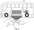
- Fig. 3 presents a simplified apparatus according to the invention, an electric bus 13, in which an arrangement according to Fig. 1 is applied.
- the primary side 1, i.e. the charging point of the electric bus 13, is arranged below a base 14, such as below the road.
- a base 14 such as below the road.
- the batteries 5 are connected in parallel to each other to form battery pairs, in which case their nominal voltage remains the same, i.e. 48 volts, but their capacity is their cumulative capacity.
- the charging side is activated and current is conducted from the batteries 5 to the electric energy charging elements 6.
- the electric energy receiving elements 7 are lowered from the underframe of the bus 13 to near the base 14 and to the point of the charging elements 6.
- the charging elements 6 supply electric energy from the charging energy storages 5 to the electric energy receiving means 7, with resonance-induction, wirelessly, and with a large amount of current, said receiving means transmitting electric energy to the electric energy storages 8, i.e. to the batteries 8, of the drive device. Charging of the batteries takes place as a rapid charge that typically lasts only a few minutes, depending on how far the electric bus 13 must drive before the next charging session. After charging of the batteries 8 has ended, the electric energy receiving means 7 are raised back inside the underframe of the bus 13 and the bus can continue its journey.
- extra-low voltage electric energy is conducted from an individual battery 8 in an electric energy transmission channel 10 to one stator pole 12 of the electric motor 11. From all the 24 batteries of the electric bus 13, extra-low voltage electric energy is conducted in independent closed circuits dedicated to the stator poles 12 of the electric motor 11.
- each closed circuit is also a current control component 9, and these current control components 9 are controlled centrally, optimizing the desired and advantageous operation of the electric motor.
- the voltage level of the charging energy source can be different to what is presented in the embodiments.
- the nominal voltage of the charging energy source can be e.g. 230 VAC.
Landscapes
- Engineering & Computer Science (AREA)
- Power Engineering (AREA)
- Transportation (AREA)
- Mechanical Engineering (AREA)
- Computer Networks & Wireless Communication (AREA)
- Life Sciences & Earth Sciences (AREA)
- Sustainable Development (AREA)
- Sustainable Energy (AREA)
- Charge And Discharge Circuits For Batteries Or The Like (AREA)
- Electric Propulsion And Braking For Vehicles (AREA)
Description
- The object of the invention is a method as defined in the preamble of
claim 1 for transmitting electric energy, and also an apparatus as defined in the preamble of claim 9 for transmitting electric energy. - In the new type of method and new type of apparatus according to the invention for electric energy transmission, electric energy is transmitted from the primary side to the electric energy storages, such as batteries, of the secondary side as extra-low voltage. On the secondary side, extra-low voltage electric energy is conducted along a plurality of independent transfer channels for the electric energy to the stator poles of the drive device, such as of an electric motor. Extra-low voltage refers to direct-current voltage (DC) up to 120 volts and to alternating-current voltage (AC) up to 50 volts. Extra-low voltage is referred to in regulations and standards as ELV (Extra Low Voltage). Since in the solution according to the invention only extra-low voltage occurs on the secondary side of the galvanically isolated primary side and secondary side, and the charging energy coming from the primary side is extra-low voltage, the secondary side of the solution is classified in its entirety as extra-low voltage. Extra-low voltage electrical devices may be constructed, repaired and installed without qualifications for electrical work. The method according to the invention can be very well applied e.g. in electrically-operated vehicles, such as in electric buses and electric cars.
- Advances in technology have made electric buses a viable option for replacing conventional diesel busses in the bus traffic of cities and built-up areas. The operating costs of an electric bus are lower than the operating costs of a diesel bus, but at present the initial investments are still higher. The energy costs of electric buses are extremely low. An electric bus consumes on average one kilowatt-hour per kilometer, but its consumption varies depending on, inter alia, the vehicle manufacturer, the driving style of the driver, and on traffic conditions and weather conditions. The consumption of an electric bus in cold, snowy and slippery road conditions in winter can increase to an average one-and-a-half kilowatt hours per kilometer. Nevertheless, electric buses promote, inter alia, the goals of Finland's Government Programme, such as the use of Finnish, carbon-free, renewable energy in traffic. Finland's Ministry of Transport and Communications has proposed that the proportion of electricity in the bus and distribution traffic of cities must be at least 70% by 2050.
- To minimize the mass to be accelerated, the battery pack should be lightweight. In this case, with fully-charged batteries the operating radius of a bus is at most approx. 100 kilometers. A typical approx. half-hour city route can be driven with a charge of less than three minutes at both ends of the route.
- So that the battery pack can be kept lightweight, so-called terminus charging is becoming established in Finland as a way of arranging electric bus services, wherein electric buses are charged during the daytime at the terminuses of a bus line, but also during the nighttime at the bus depot.
- Charging devices can also be disposed elsewhere along the route. Route-side charging is generally performed using a heavy-duty (≥ 300 kW) current collector charger, which means charging occurring from above the electric bus. Current collector charging is an automatic charging method that can be used both for depot charging and for in-service rapid charging. When using a charging device, the component transmitting electric current to the bus, i.e. the pantograph, can be disposed either in the charging device or in the electric bus itself. Current collector charging technology at its best enables charging of up to 450 kW.
- In addition to the current collector charging generally used in urban areas, other methods for the rapid charging of electric buses also exist, such as induction charging, in which automatic charging occurring from underneath the bus is used. Induction charging occurs between a primary winding installed in the ground and a secondary winding installed in the bus, without a contact surface. For proper functioning, induction charging devices require good operating conditions, and even minor detriments such as e.g. tree leaves, sand, rubbish, snow and ice can prevent successful charging. The positioning of an electric bus on an induction charging device also requires an automatic detection system for the electric bus. Induction charging is particularly well suited to buses because they are used on very regular services on a certain route. It reduces the size of the batteries needed and shortens unavoidable standstill times. There are also savings in costs compared to electric buses with larger batteries, regardless of the fact that charging bases are needed at bus stops.
- Charging at the bus depot is generally performed using cable charging, in which moderate 20-50 kW charging powers are used in order to minimize costs. In cable charging, the charging cable must be connected by hand to the electric bus. Owing to this, cable charging is best suited to depot charging, when the servicing personnel for electric buses can handle connection of the charging cables.
- For the most demanding battery-powered applications, such as the power source for the motors of electric cars and electric buses, battery packs according to modern technology are generally used, the battery packs producing the voltage of approx. 300 - 700 volts required for electric motors. Sufficient voltage is obtained by connecting hundreds of low-voltage, in terms of their nominal voltage (e.g. 3.6 volts), batteries in series. In addition, it is very general that the current to electric motors is further converted into three-phase alternating-voltage current.
- Some other problems in existing solutions, in addition to modest operating radius and high price, include ensuring the operating safety of electric vehicles, which is demanding when the operating voltage of the environment exceeds the aforementioned limit for extra-low voltage. To achieve the required level of electrical safety, highvoltage batter circuits must be insulated, i.e. isolated, which increases the thickness, weight and costs of the structures. High charging currents also require large fuse sizes, which in turn incurs higher costs in electrical connections. Higher operating voltages of an apparatus stress the technical components, such as the power components, in which case apparatuses age faster and require more frequent servicing. Also power losses and heat losses are high, directly and indirectly affecting costs through, inter alia, the rapid ageing of various components and the need for extra cooling solutions. In addition, all the servicing personnel that operate with apparatus on the secondary side, i.e. on the side on which the drive device and electric energy storages for the drive device are situated, must possess a qualification to perform electrical work, or must work under the supervision of a person with an electrical qualification. This restricts and hampers the servicing procedures for devices, such as e.g. electric buses, incurring extra costs in servicing activities.
- Another problem in existing systems is their poor reliability and poor redundancy. If, in some phase of the process of charging, the electric energy storages of a device disruptions occur in the electric energy storages themselves or in using the drive device, there is a high risk that the drive device cannot be utilized before servicing arrives.
- One inductive charging system according to prior art is disclosed in patent specification no.
WO 2014207267 A1 . However, this specification does not present the system being based on the use of extra-low voltage. The problems and risks described above are attached to the use of higher voltage. - Another solution according to prior art is presented in patent specification no.
WO 2017041144 A1 , which presents a method for transmitting electric energy, the method comprising on the primary side at least one charging energy source and at least one converter, and also on the secondary side at least one drive device with rotor and with stator provided with poles, and more than one electric energy storage for the drive device, as well as at least one transfer channel for electric energy. The system does not, however, appear to be based on the use of extra-low voltage. - Yet another solution according to prior art is presented in publication Patzak, Adrian et al, ISCAD - Electric High Performance Drive for Individual Mobility at Extra-Low Voltages, SAE International journal of alternative powertrains, 2016, Vol.5, p.148-156. The publication presents an extra-low voltage drive method, in which extra-low voltage electric energy is conducted to the stator poles in a closed circuit from the electric energy storage for the drive device, and in which extra-low voltage electric energy is conducted from each electric energy storage for the drive device in a closed circuit via its own independent current control component and its own independent electric energy transmission channel to the drive device, to at least one stator pole.
- None of the cited documents show the features of the pending invention, in which more than one charging element using extra-low voltage is arranged on the primary side, and the same number of electric energy receiving elements, electric energy storages for the drive device, current control components and outgoing electric energy transmission channels, all of which using extra-low voltage, are arranged on the secondary side of the apparatus as there are charging elements arranged on the primary side of the apparatus.
- The aim of the present invention is to eliminate the aforementioned drawbacks and to provide a safe, effective and economic method and apparatus for transmitting electric energy. The method according to the invention for transmitting electric energy is characterized by what is disclosed in the characterization part of
claim 1, and the apparatus according to the invention for transmitting electric energy is characterized by what is disclosed in the characterization part of claim 9. Other embodiments of the invention are characterized by what is disclosed in the other claims. - In the method according to the invention for transmitting electric energy, the primary side of the method comprises at least one charging energy source and at least one transformer, and also on the secondary side more than one electric energy storage for the drive device, at least one transfer channel for electric energy and at least one drive device. In the method more than one charging element using extra-low voltage is arranged on the primary side. The same number of electric energy receiving elements, electric energy storages for the drive device, current control components and outgoing electric energy transmission channels, all of which using extra-low voltage, are arranged on the secondary side of the apparatus as there are charging elements arranged in the apparatus. From each electric energy storage for the drive device extra-low voltage electric energy is conducted in a closed circuit via its own independent current control component and its own independent electric energy transmission channel to the drive device, to at least one stator pole.
- One substantial advantage, among others, of the method and apparatus according to the invention, hereinafter referred to more briefly as the solution, is that the necessary extra-low voltage electric energy is channeled to the drive device, to a number of stator poles, in which case the whole of the operating environment of the drive device, i.e. on the secondary side, functions purely in the extra-low voltage range. When the voltages are finally summed in the drive device, the same electric power is obtained as is used e.g. in electric buses operating with normal high voltages of approx. 700 volts. Another advantage is also that by means of the solution direct-voltage current supply to an electric motor is arrangeable in the same way as if the current were three-phase alternating-voltage current. The advantages of operating with extra-low voltage include a clear improvement in the electrical safety of the operating environment. Low direct-voltage current of extra-low voltage is not life-threatening to people. According to current safety regulations, electrical qualifications are not required of persons working in an extra-low voltage environment, which facilitates e.g. using personnel in installation and servicing of the drive device. Using extra-low voltage enables lighter insulations and cooling solutions and also simpler supervisions and circuits. Furthermore, an extra-low voltage environment does not stress the components of the operating environment in the same way as higher voltages, in which case the failure rate of the system improves and servicing intervals are longer. All the aforementioned issues significantly reduce the acquisition and operating costs of the apparatus.
- Another advantage is the redundancy of the operating environment on both the primary side and the secondary side. The primary side has more than one unit of all the components needed for charging, and charging would continue without interruption even if one of the components were to fail. On the secondary side, the transmission of electric energy to the drive device is arranged by means of a number of independent, extra-low voltage, electric energy transmission channels, and there are the same number of electric energy storages, i.e. batteries, for the drive device as there are independent electric energy transmission channels in use. When there is a disruption of current supply in an individual channel. the operation of the drive device will continue because the other channels supply current to the drive device from their own independent batteries normally.
- Another advantage is the improved availability of batteryoperated devices, such as e.g. wireless charging, and longer battery duration. With the method and apparatus according to the invention e.g. charging energy storages, such as batteries, on the primary side can be continuously charged while also little by little saving electricity costs, because the fuse size of the charging current source does not need to be large. When a drive device, such as an electric bus, arrives at the charging station, a rapid charge of the batteries of the electric bus from the charging energy storages is performed with a large amount of current but with little voltage, in which case the charging time can be very short, even just a few minutes, and the electric bus has new electric energy to continue driving again until the next charging interval.
- In the following, the invention will be described in greater detail by the aid of some embodiments and by referring to the attached simplified drawings, wherein
- Fig. 1
- presents simplified diagram of one embodiment according to the invention,
- Fig. 2
- presents a simplified diagram of a second embodiment according to the invention,
- Fig. 3
- presents one simplified apparatus, an electric bus, according to the invention in which an arrangement according to
Fig. 1 is applied. -
Fig. 1 presents a simplified diagram of one embodiment according to the invention for transmitting electric energy to adrive device 11 and for charging electric energy into the electric energy storages 8 of the drive device. In the arrangement, the environment is divided into two sides: theprimary side 1, i.e. the electric energy charging side, and thesecondary side 2, i.e. the electric energy receiving side. Theprimary side 1 andsecondary side 2 are galvanically isolated 3 from each other. In practice, this means that theprimary side 1 and thesecondary side 2 are not physically in contact with each other, but instead the transmission of electric energy from theprimary side 1 to thesecondary side 2 is implemented completely wirelessly through electromagnetic induction. - Three-phase alternating-voltage current, the voltage level of which is 400 volts, functions as the source of the charging energy. In the embodiment there are two charging energy sources, separate from each other, functioning behind their own fuses. The current is conducted to
converters 4, which transform the current into direct-voltage current and reduce the voltage level to 48 volts. With this 48-volt direct-voltage current, two 48-volt chargingenergy storages 5, such as batteries, are charged. Charging is performed continuously with a small amount of current, in which case small fuse sizes can be used, which in turn has a reducing effect on electricity procurement costs. The chargingenergy storages 5 are preferably highcapacity batteries, in which case they can quickly deliver current to thesecondary side 2 via a number of chargingelements 6. Since there are two, or even more, charging energy sources and chargingenergy storages 5, redundancy is achieved on theprimary side 1, i.e. if some component on theprimary side 1 fails, theprimary side 1 is nevertheless able to continue the supply of electric energy to thesecondary side 2. - From the charging
energy storages 5 electric energy is transmitted from theprimary side 1 by means of the chargingelements 6 to thesecondary side 2. In the embodiment according to the figure, there are 24 units of chargingelements 6. At its simplest, a chargingelement 6 is a coil component, i.e. a winding, that creates an electromagnetic field around itself. On thesecondary side 2 the electricenergy receiving element 7, which is a coil component corresponding to the chargingelement 6, receives the charging energy. Transmission of electric energy from theprimary side 1 to thesecondary side 2 takes place as induction charging, which is based on electromagnetic induction, and the charging method is completely wireless. It is advantageous to implement wireless power transmission as resonance-based resonance-induction, which improves efficiency in the transmission of electric energy. Each chargingelement 6 of theprimary side 1 has one electricenergy receiving element 7 on thesecondary side 2. - The
energy receiving element 7 transmits the 48-volt electric energy it receives to the electric energy storage 8, such as a battery, of the drive device. Each electric energy receiving means 7 has its own electric energy storage 8 for the drive device, i.e. there are as many electric energy storages 8 for the drive device as there are electric energy receiving means 7. In this embodiment, therefore, there are 24 battery units for thedrive device 11. - From the electric energy storage 8 for the drive device the electric energy is conducted to a current control component 9, such as e.g. to an H bridge component, by means of which the current supply and current polarity, i.e. travel direction, to the
drive device 11 can be controlled. Each electric energy storage 8 for the drive device has its own individual current control component 9. The current control components are controlled centrally by means of a current control system, which enables optimal electric energy supply and control of the polarity of current to thedrive device 11. From each current control component 9 the electric energy is transmitted along electricenergy transmission channels 10 to thedrive device 11. - The
drive device 11 is anelectric motor 11 that has 24 units ofstator poles 12. Astator pole 12 is a coil component, i.e. a winding, in the stator, to which component electric energy is conducted by means of two conductors. To eachstator pole 12 is connected its own individual electric energy storage 8 for the drive device, its own individual current control component 9 and its own individual electricenergy transmission channel 10, along which 48-volt electric energy is supplied in a closed circuit to thestator pole 12. By controlling the current control components 9 suitably to supply extra-low voltage electric energy to thestator poles 12, an electric motor can be made to function just like e.g. a normal three-phase electric motor using alternating-voltage current. With the current control components 9 the polarity of the current can be changed, in which case theelectric motor 11 rotates in the opposite direction. Eachstator pole 12 of theelectric motor 11 has its own independent 48-volt circuit, and in none of the system components does the operating voltage exceed a voltage of 48 volts. Although the electric energy voltages in the system do not exceed 48 volts, when they are summed together for the drive device they correspond in power terms to higher-voltage operating environments. - Since the
primary side 1 is galvanically isolated 3 from thesecondary side 2, and the operating voltages on thesecondary side 2 are kept in separate electricenergy transmission channels 10, in which case their voltage levels do not rise to higher than 48 volts, thesecondary side 2 can be classified as a completely extra-low voltage environment. Extra-low voltage refers to direct-current voltage (DC) up to 120 volts and to alternating-current voltage (AC) up to 50 volts. Extra-low voltage is referred to in regulations and standards as ELV (Extra Low Voltage). The operating environment in question classified as extra-low voltage is electrically safe and extremely costefficient. Extra-low voltage electrical devices may be constructed, repaired and installed without qualifications for electrical work. - In the embodiments presented above there were 24 units of charging
elements 6, of electricenergy receiving elements 7, of electric energy storages 8 for the drive device, of current control components 9, of electricenergy transmission channels 10, and ofstator poles 12 of thedrive device 11. The number of these components can very well vary, depending on e.g. the intended use of the drive device or on the level of extra-low voltage to be used. The numbers can range between e.g. 8 - 36 units. -
Fig. 2 presents a simplified diagram of a second embodiment according to the invention. The solution of theprimary side 1 corresponds to what is presented inFig.1 , but there are only three units oftransmission elements 6. Correspondingly, on the secondary side there are three electricenergy receiving elements 7, three electric energy storages 8 for the drive device, three current control components 9, and three outgoing electricenergy transmission channels 10 for thedrive device 11. For the sake of clarity, there are only three units of each component, but in the actual embodiments there can also be many more of these components. In thedrive device 11, such as in an electric motor, there are correspondingly double the number ofstator poles 12, i.e. in this embodiment six units. From one electric energy storage 8 for the drive device, electric energy is conducted via an electricenergy transmission channel 10 to twostator poles 12, which are disposed on opposite sides of the rim of the rotor of theelectric motor 11, and the current in theopposite stator poles 12 is conducted to travel in different directions, i.e. with different polarity. - Since in the embodiments presented above there are on the secondary side 2 a number of electric energy storages 8 for the drive device, of current control components 9 and of electric
energy transmission channels 10, redundancy is achieved on thesecondary side 2, i.e. if some component on thesecondary side 2 possibly fails, thesecondary side 2 is nevertheless able to continue the supply of electric energy to theelectric motor 11, and theelectric motor 11 remains operational. -
Fig. 3 presents a simplified apparatus according to the invention, anelectric bus 13, in which an arrangement according toFig. 1 is applied. - The
primary side 1, i.e. the charging point of theelectric bus 13, is arranged below a base 14, such as below the road. At the charging station are two separate three-phase chargingcurrent sources 4a, from which extra-low voltage electric energy is supplied continuously viaconverters 4 to chargingenergy storages 5, such as tobatteries 5. Thebatteries 5 are connected in parallel to each other to form battery pairs, in which case their nominal voltage remains the same, i.e. 48 volts, but their capacity is their cumulative capacity. When thebus 13 arrives at the charging location, the charging side is activated and current is conducted from thebatteries 5 to the electricenergy charging elements 6. The electricenergy receiving elements 7 are lowered from the underframe of thebus 13 to near the base 14 and to the point of the chargingelements 6. Normally there are solutions at the charging location that facilitate positioning of thebus 13. The chargingelements 6 supply electric energy from the chargingenergy storages 5 to the electric energy receiving means 7, with resonance-induction, wirelessly, and with a large amount of current, said receiving means transmitting electric energy to the electric energy storages 8, i.e. to the batteries 8, of the drive device. Charging of the batteries takes place as a rapid charge that typically lasts only a few minutes, depending on how far theelectric bus 13 must drive before the next charging session. After charging of the batteries 8 has ended, the electric energy receiving means 7 are raised back inside the underframe of thebus 13 and the bus can continue its journey. - In an independent closed circuit, extra-low voltage electric energy is conducted from an individual battery 8 in an electric
energy transmission channel 10 to onestator pole 12 of theelectric motor 11. From all the 24 batteries of theelectric bus 13, extra-low voltage electric energy is conducted in independent closed circuits dedicated to thestator poles 12 of theelectric motor 11. In each closed circuit is also a current control component 9, and these current control components 9 are controlled centrally, optimizing the desired and advantageous operation of the electric motor. - It is obvious to the person skilled in the art that different embodiments of the invention are not limited to the example described above, but that they may be varied within the scope of the claims presented below. What is essential in the invention is that only extra-low voltages are used on the secondary side of the arrangement and that the current supply to the drive device is channeled with a plurality of separate extra-low voltage circuits. Thus, for example, the extra-low voltages presented can differ from the 48 volts used in the embodiments, so long as the voltage does not exceed the internationally specified limit value for extra-low voltage.
- It is also obvious to the person skilled in the art that in the method and apparatus according to the invention, the numbers of components, such as charging elements, batteries and current control components, can be different to what is presented in the embodiments.
- It is also obvious to the person skilled in the art that in the method and apparatus according to the invention, the voltage level of the charging energy source can be different to what is presented in the embodiments. The nominal voltage of the charging energy source can be e.g. 230 VAC.
- It is further obvious to the person skilled in the art that in the method and apparatus according to the invention, instead of batteries, also other electric energy storages suited to the purpose, e.g. capacitors, preferably supercapacitors, can be used as a charging energy storage or as an electric energy storage for the drive device.
Claims (15)
- Method for transmitting electric energy, the method comprising on the primary side (1) at least one charging energy source and at least one converter (4), and also on the secondary side (2) at least one drive device (11) with rotor and with stator provided with poles (12), and more than one electric energy receiving element (7), electric energy storage (8) for the drive device (11) and current control component (9), as well as at least one outgoing electric energy transfer channel (10) for electric energy, characterized in that in the method more than one charging element (6) using extra-low voltage is arranged on the primary side (1), and in that the same number of electric energy receiving elements (7), electric energy storages (8), current control components (9) and outgoing electric energy transmission channels (10), all of which using extra-low voltage, are arranged on the secondary side (2) of the apparatus as there are charging elements (6) arranged on the primary side (1), and in that extra-low voltage electric energy is conducted to the stator poles (12) in a closed circuit from the electric energy storage (8) for the drive device, and in that from each electric energy storage (8) for the drive device extra-low voltage electric energy is conducted in a closed circuit via its own independent current control component (9) and its own independent electric energy transmission channel (10) to the drive device (11), to at least one stator pole (12).
- Method according to claim 1 for transmitting electric energy, characterized in that the extra-low voltage charging energy produced by the converter (4) is stored in at least one charging energy storage (5) of the primary side (1) .
- Method according to claim 1 or 2 for transmitting electric energy, characterized in that in the method only extra-low voltage electric energy is used on the secondary side (2), and in that only extra-low voltage electric energy is used in the charging energy storages (5) of the primary side (1) as well as in the charging elements (6).
- Method according to claim 1, 2 or 3 for transmitting electric energy, characterized in that the primary side (1) charging electric energy and the secondary side (2) receiving electric energy are galvanically (3) isolated from each other.
- Method according to any of the preceding claims for transmitting electric energy, characterized in that electric energy is charged from the primary side (1) to the secondary side (2) wirelessly as induction charging.
- Method according to any of the preceding claims for transmitting electric energy, characterized in that the amount and polarity of the electric energy leaving an electric energy storage (8) of the drive device to the drive device (11) is adjusted by means of the current control component (9).
- Method according to any of the preceding claims for transmitting electric energy, characterized in that from each electric energy storage (8) of the drive device its own independent electric energy transmission channel (10) is conducted to one stator pole (12) of the drive device (11) .
- Method according to any of the preceding claims 1-6 for transmitting electric energy, characterized in that from each electric energy storage (8) of the drive device electric energy is conducted via electric energy transmission channels (10) to two opposite stator poles (12) of the drive device (11).
- Apparatus for transmitting electric energy, the apparatus comprising on the primary side (1) at least one charging energy source and at least one converter (4), and on the secondary side (2) a drive device (11) provided with a rotor and a stator provided with poles (12), more than one electric energy receiving element (7), electric energy storage (8) for the drive device (11) and current control component (9), and at least one outgoing electric energy transmission channel (10), characterized in that the primary side (1) of the apparatus comprises more than one charging element (6) using extra-low voltage, and in that the secondary side (2) comprises the same number of electric energy receiving elements (7), electric energy storages (8) in connection with current control components (9) and outgoing electric energy transmission channels (10), all of which using extra-low voltage, as there are charging elements (6) in the apparatus, and in that the drive device (11) comprises at least the number of extra-low voltage receiving stator poles (12) according to the number of charging elements (6), and that each electric energy receiving element (7) is connected to its own electric energy storage (8), and that the secondary side (2) comprises a closed circuit between each electric energy storage (8) and at least one stator pole (12).
- Apparatus according to claim 9 for transmitting electric energy, characterized in that the primary side (1) of the apparatus comprises more than one charging energy source, converter (4) and charging energy storage (5).
- Apparatus according to claim 9 or 10 for transmitting electric energy, characterized in that the apparatus comprises galvanic isolation (3) of the primary side (1) and the secondary side (2).
- Apparatus according to claim 9, 10 or 11 for transmitting electric energy, characterized in that there are 8 - 36 units of charging elements (6) in the apparatus.
- Apparatus according to any of the preceding claims 9-12 for transmitting electric energy, characterized in that the primary side (1) of the apparatus preferably comprises 24 units of charging elements (6).
- Apparatus according to any of the preceding claims 9-13 for transmitting electric energy, characterized in that the drive device (11) comprises the same number of stator poles (12) as there are charging elements (6) on the primary side (1) .
- Apparatus according to any of the preceding claims 10-13 for transmitting electric energy, characterized in that the drive device (11) comprises twice the number of stator poles (12) as there are charging elements (6) on the primary side (1), and in that from one electric energy storage (8) for the drive device a circuit is connected by means of an electric energy transmission channel (10) to two opposite stator poles (12) of the drive device (11), and in that current in the opposite stator poles (12) is conducted to travel in different directions.
Applications Claiming Priority (2)
| Application Number | Priority Date | Filing Date | Title |
|---|---|---|---|
| FI20175812A FI128169B (en) | 2017-09-13 | 2017-09-13 | Method and apparatus for transmitting electric energy |
| PCT/FI2018/050654 WO2019053329A1 (en) | 2017-09-13 | 2018-09-12 | Method and apparatus for transmitting electric energy |
Publications (3)
| Publication Number | Publication Date |
|---|---|
| EP3682526A1 EP3682526A1 (en) | 2020-07-22 |
| EP3682526A4 EP3682526A4 (en) | 2021-06-02 |
| EP3682526B1 true EP3682526B1 (en) | 2023-05-24 |
Family
ID=65723973
Family Applications (1)
| Application Number | Title | Priority Date | Filing Date |
|---|---|---|---|
| EP18855581.7A Active EP3682526B1 (en) | 2017-09-13 | 2018-09-12 | Method and apparatus for transmitting electric energy |
Country Status (3)
| Country | Link |
|---|---|
| EP (1) | EP3682526B1 (en) |
| FI (1) | FI128169B (en) |
| WO (1) | WO2019053329A1 (en) |
Family Cites Families (5)
| Publication number | Priority date | Publication date | Assignee | Title |
|---|---|---|---|---|
| FR2939983B1 (en) * | 2008-12-11 | 2010-12-31 | Liebherr Aerospace Toulouse Sas | DEVICE WITH POLYPHASE ELECTRIC MACHINE AND ELECTRIC MACHINE THEREFOR |
| FR2967310B1 (en) * | 2010-11-04 | 2013-08-02 | Xap | ELECTROMAGNETIC MOTOR WITHOUT BRUSH |
| WO2014207267A1 (en) | 2013-06-28 | 2014-12-31 | Fundación Circe - Centro De Investigacion De Recursos Y Consumos Energeticos | Modular inductive charging system for electric vehicles |
| DE102014105642A1 (en) * | 2014-04-22 | 2015-10-22 | Feaam Gmbh | Electric machine |
| EP3347963A4 (en) | 2015-09-11 | 2019-01-16 | Invertedpower Pty Ltd | CONTROLLER FOR INDUCTIVE LOAD HAVING ONE OR MORE INDUCTIVE WINDINGS |
-
2017
- 2017-09-13 FI FI20175812A patent/FI128169B/en active IP Right Grant
-
2018
- 2018-09-12 EP EP18855581.7A patent/EP3682526B1/en active Active
- 2018-09-12 WO PCT/FI2018/050654 patent/WO2019053329A1/en not_active Ceased
Also Published As
| Publication number | Publication date |
|---|---|
| EP3682526A1 (en) | 2020-07-22 |
| FI128169B (en) | 2019-11-29 |
| FI20175812A1 (en) | 2019-03-14 |
| EP3682526A4 (en) | 2021-06-02 |
| WO2019053329A1 (en) | 2019-03-21 |
Similar Documents
| Publication | Publication Date | Title |
|---|---|---|
| JP6266612B2 (en) | System and method for operating a hybrid vehicle system | |
| US11351885B2 (en) | Charging infrastructure unit, and charging infrastructure having a charging power option | |
| CN112550072B (en) | Energy systems for electric vehicles | |
| US20140167697A1 (en) | Electric battery charging installation and method | |
| EP2872359B1 (en) | Energy management system for railbound vehicles | |
| CN107303825A (en) | For the charging system of electric vehicle and for the method to electric vehicle charging | |
| CN102785592A (en) | Method for supplying power to a railway vehicle, station supply system, on-board power-storage system and rail vehicle | |
| US12434642B2 (en) | Power supply system and method | |
| US20140239879A1 (en) | Battery charging system | |
| CN108656955B (en) | Direct-current high-voltage box, double-system high-voltage traction system and electric motor train unit | |
| US20250074201A1 (en) | Power supply for a rail vehicle, having a traction battery | |
| JP2013141374A (en) | Electric power supply system for electric railroad | |
| Suzuki et al. | Application examples of energy saving measures in Japanese DC feeding system | |
| US8552681B2 (en) | Power storage system for a rail-guided vehicle | |
| EP3682526B1 (en) | Method and apparatus for transmitting electric energy | |
| US20250170902A1 (en) | Electrical traction system for an industrial electric vehicle, industrial electric vehicle, electrical power supply system and method of providing electrical energy to an industrial electric vehicle | |
| EP2451690B1 (en) | Aerial able car system having transportation operating equipment for passenger and/or freight transport | |
| Tudor et al. | The electric bus is an optimized trolleybus | |
| Bartłomiejczyk et al. | Energy savings by application of supercapacitor storage in trolleybus supplying station–analysis of experimental results | |
| Gelman | Comparison between wayside storage and reversible thyristor controlled rectifiers (rtcr) for heavy rail applications | |
| NL2031027B1 (en) | Reduced dissipation converter for battery-buffered fast-charging of electric vehicles. | |
| Ruvio et al. | Opportunity Charging for Public Transport: Technical Standards and Future Perspectives | |
| CN121105826A (en) | Vehicle power supply system and method | |
| Genovese et al. | Fast charge and local public transport: an Italian experience | |
| CN104477117A (en) | Power distribution system for plug-in hybrid power system as well as control method and control system of power distribution system |
Legal Events
| Date | Code | Title | Description |
|---|---|---|---|
| STAA | Information on the status of an ep patent application or granted ep patent |
Free format text: STATUS: THE INTERNATIONAL PUBLICATION HAS BEEN MADE |
|
| PUAI | Public reference made under article 153(3) epc to a published international application that has entered the european phase |
Free format text: ORIGINAL CODE: 0009012 |
|
| STAA | Information on the status of an ep patent application or granted ep patent |
Free format text: STATUS: REQUEST FOR EXAMINATION WAS MADE |
|
| 17P | Request for examination filed |
Effective date: 20200410 |
|
| AK | Designated contracting states |
Kind code of ref document: A1 Designated state(s): AL AT BE BG CH CY CZ DE DK EE ES FI FR GB GR HR HU IE IS IT LI LT LU LV MC MK MT NL NO PL PT RO RS SE SI SK SM TR |
|
| AX | Request for extension of the european patent |
Extension state: BA ME |
|
| DAV | Request for validation of the european patent (deleted) | ||
| DAX | Request for extension of the european patent (deleted) | ||
| A4 | Supplementary search report drawn up and despatched |
Effective date: 20210503 |
|
| RIC1 | Information provided on ipc code assigned before grant |
Ipc: H02J 7/02 20160101AFI20210426BHEP Ipc: H02J 7/00 20060101ALI20210426BHEP Ipc: H02J 5/00 20160101ALI20210426BHEP Ipc: H02J 50/12 20160101ALI20210426BHEP Ipc: H02M 7/02 20060101ALI20210426BHEP Ipc: H02K 3/00 20060101ALI20210426BHEP Ipc: H02K 37/00 20060101ALI20210426BHEP Ipc: B60L 3/00 20190101ALI20210426BHEP Ipc: H02P 4/00 20060101ALI20210426BHEP Ipc: H02P 25/22 20060101ALI20210426BHEP Ipc: H02P 27/08 20060101ALI20210426BHEP |
|
| GRAP | Despatch of communication of intention to grant a patent |
Free format text: ORIGINAL CODE: EPIDOSNIGR1 |
|
| STAA | Information on the status of an ep patent application or granted ep patent |
Free format text: STATUS: GRANT OF PATENT IS INTENDED |
|
| INTG | Intention to grant announced |
Effective date: 20221219 |
|
| GRAS | Grant fee paid |
Free format text: ORIGINAL CODE: EPIDOSNIGR3 |
|
| GRAA | (expected) grant |
Free format text: ORIGINAL CODE: 0009210 |
|
| STAA | Information on the status of an ep patent application or granted ep patent |
Free format text: STATUS: THE PATENT HAS BEEN GRANTED |
|
| AK | Designated contracting states |
Kind code of ref document: B1 Designated state(s): AL AT BE BG CH CY CZ DE DK EE ES FI FR GB GR HR HU IE IS IT LI LT LU LV MC MK MT NL NO PL PT RO RS SE SI SK SM TR |
|
| REG | Reference to a national code |
Ref country code: GB Ref legal event code: FG4D |
|
| REG | Reference to a national code |
Ref country code: CH Ref legal event code: EP |
|
| REG | Reference to a national code |
Ref country code: DE Ref legal event code: R096 Ref document number: 602018050310 Country of ref document: DE |
|
| REG | Reference to a national code |
Ref country code: AT Ref legal event code: REF Ref document number: 1570155 Country of ref document: AT Kind code of ref document: T Effective date: 20230615 |
|
| REG | Reference to a national code |
Ref country code: IE Ref legal event code: FG4D |
|
| REG | Reference to a national code |
Ref country code: LT Ref legal event code: MG9D |
|
| REG | Reference to a national code |
Ref country code: NL Ref legal event code: MP Effective date: 20230524 |
|
| REG | Reference to a national code |
Ref country code: AT Ref legal event code: MK05 Ref document number: 1570155 Country of ref document: AT Kind code of ref document: T Effective date: 20230524 |
|
| PG25 | Lapsed in a contracting state [announced via postgrant information from national office to epo] |
Ref country code: SE Free format text: LAPSE BECAUSE OF FAILURE TO SUBMIT A TRANSLATION OF THE DESCRIPTION OR TO PAY THE FEE WITHIN THE PRESCRIBED TIME-LIMIT Effective date: 20230524 Ref country code: PT Free format text: LAPSE BECAUSE OF FAILURE TO SUBMIT A TRANSLATION OF THE DESCRIPTION OR TO PAY THE FEE WITHIN THE PRESCRIBED TIME-LIMIT Effective date: 20230925 Ref country code: NO Free format text: LAPSE BECAUSE OF FAILURE TO SUBMIT A TRANSLATION OF THE DESCRIPTION OR TO PAY THE FEE WITHIN THE PRESCRIBED TIME-LIMIT Effective date: 20230824 Ref country code: NL Free format text: LAPSE BECAUSE OF FAILURE TO SUBMIT A TRANSLATION OF THE DESCRIPTION OR TO PAY THE FEE WITHIN THE PRESCRIBED TIME-LIMIT Effective date: 20230524 Ref country code: ES Free format text: LAPSE BECAUSE OF FAILURE TO SUBMIT A TRANSLATION OF THE DESCRIPTION OR TO PAY THE FEE WITHIN THE PRESCRIBED TIME-LIMIT Effective date: 20230524 Ref country code: AT Free format text: LAPSE BECAUSE OF FAILURE TO SUBMIT A TRANSLATION OF THE DESCRIPTION OR TO PAY THE FEE WITHIN THE PRESCRIBED TIME-LIMIT Effective date: 20230524 |
|
| PG25 | Lapsed in a contracting state [announced via postgrant information from national office to epo] |
Ref country code: RS Free format text: LAPSE BECAUSE OF FAILURE TO SUBMIT A TRANSLATION OF THE DESCRIPTION OR TO PAY THE FEE WITHIN THE PRESCRIBED TIME-LIMIT Effective date: 20230524 Ref country code: PL Free format text: LAPSE BECAUSE OF FAILURE TO SUBMIT A TRANSLATION OF THE DESCRIPTION OR TO PAY THE FEE WITHIN THE PRESCRIBED TIME-LIMIT Effective date: 20230524 Ref country code: LV Free format text: LAPSE BECAUSE OF FAILURE TO SUBMIT A TRANSLATION OF THE DESCRIPTION OR TO PAY THE FEE WITHIN THE PRESCRIBED TIME-LIMIT Effective date: 20230524 Ref country code: LT Free format text: LAPSE BECAUSE OF FAILURE TO SUBMIT A TRANSLATION OF THE DESCRIPTION OR TO PAY THE FEE WITHIN THE PRESCRIBED TIME-LIMIT Effective date: 20230524 Ref country code: IS Free format text: LAPSE BECAUSE OF FAILURE TO SUBMIT A TRANSLATION OF THE DESCRIPTION OR TO PAY THE FEE WITHIN THE PRESCRIBED TIME-LIMIT Effective date: 20230924 Ref country code: HR Free format text: LAPSE BECAUSE OF FAILURE TO SUBMIT A TRANSLATION OF THE DESCRIPTION OR TO PAY THE FEE WITHIN THE PRESCRIBED TIME-LIMIT Effective date: 20230524 Ref country code: GR Free format text: LAPSE BECAUSE OF FAILURE TO SUBMIT A TRANSLATION OF THE DESCRIPTION OR TO PAY THE FEE WITHIN THE PRESCRIBED TIME-LIMIT Effective date: 20230825 |
|
| PG25 | Lapsed in a contracting state [announced via postgrant information from national office to epo] |
Ref country code: FI Free format text: LAPSE BECAUSE OF FAILURE TO SUBMIT A TRANSLATION OF THE DESCRIPTION OR TO PAY THE FEE WITHIN THE PRESCRIBED TIME-LIMIT Effective date: 20230524 |
|
| PG25 | Lapsed in a contracting state [announced via postgrant information from national office to epo] |
Ref country code: SK Free format text: LAPSE BECAUSE OF FAILURE TO SUBMIT A TRANSLATION OF THE DESCRIPTION OR TO PAY THE FEE WITHIN THE PRESCRIBED TIME-LIMIT Effective date: 20230524 |
|
| PG25 | Lapsed in a contracting state [announced via postgrant information from national office to epo] |
Ref country code: SM Free format text: LAPSE BECAUSE OF FAILURE TO SUBMIT A TRANSLATION OF THE DESCRIPTION OR TO PAY THE FEE WITHIN THE PRESCRIBED TIME-LIMIT Effective date: 20230524 Ref country code: SK Free format text: LAPSE BECAUSE OF FAILURE TO SUBMIT A TRANSLATION OF THE DESCRIPTION OR TO PAY THE FEE WITHIN THE PRESCRIBED TIME-LIMIT Effective date: 20230524 Ref country code: RO Free format text: LAPSE BECAUSE OF FAILURE TO SUBMIT A TRANSLATION OF THE DESCRIPTION OR TO PAY THE FEE WITHIN THE PRESCRIBED TIME-LIMIT Effective date: 20230524 Ref country code: EE Free format text: LAPSE BECAUSE OF FAILURE TO SUBMIT A TRANSLATION OF THE DESCRIPTION OR TO PAY THE FEE WITHIN THE PRESCRIBED TIME-LIMIT Effective date: 20230524 Ref country code: DK Free format text: LAPSE BECAUSE OF FAILURE TO SUBMIT A TRANSLATION OF THE DESCRIPTION OR TO PAY THE FEE WITHIN THE PRESCRIBED TIME-LIMIT Effective date: 20230524 Ref country code: CZ Free format text: LAPSE BECAUSE OF FAILURE TO SUBMIT A TRANSLATION OF THE DESCRIPTION OR TO PAY THE FEE WITHIN THE PRESCRIBED TIME-LIMIT Effective date: 20230524 |
|
| REG | Reference to a national code |
Ref country code: DE Ref legal event code: R097 Ref document number: 602018050310 Country of ref document: DE |
|
| PLBE | No opposition filed within time limit |
Free format text: ORIGINAL CODE: 0009261 |
|
| STAA | Information on the status of an ep patent application or granted ep patent |
Free format text: STATUS: NO OPPOSITION FILED WITHIN TIME LIMIT |
|
| REG | Reference to a national code |
Ref country code: DE Ref legal event code: R119 Ref document number: 602018050310 Country of ref document: DE |
|
| REG | Reference to a national code |
Ref country code: CH Ref legal event code: PL |
|
| 26N | No opposition filed |
Effective date: 20240227 |
|
| PG25 | Lapsed in a contracting state [announced via postgrant information from national office to epo] |
Ref country code: SI Free format text: LAPSE BECAUSE OF FAILURE TO SUBMIT A TRANSLATION OF THE DESCRIPTION OR TO PAY THE FEE WITHIN THE PRESCRIBED TIME-LIMIT Effective date: 20230524 |
|
| PG25 | Lapsed in a contracting state [announced via postgrant information from national office to epo] |
Ref country code: LU Free format text: LAPSE BECAUSE OF NON-PAYMENT OF DUE FEES Effective date: 20230912 |
|
| REG | Reference to a national code |
Ref country code: BE Ref legal event code: MM Effective date: 20230930 |
|
| GBPC | Gb: european patent ceased through non-payment of renewal fee |
Effective date: 20230912 |
|
| PG25 | Lapsed in a contracting state [announced via postgrant information from national office to epo] |
Ref country code: SI Free format text: LAPSE BECAUSE OF FAILURE TO SUBMIT A TRANSLATION OF THE DESCRIPTION OR TO PAY THE FEE WITHIN THE PRESCRIBED TIME-LIMIT Effective date: 20230524 Ref country code: LU Free format text: LAPSE BECAUSE OF NON-PAYMENT OF DUE FEES Effective date: 20230912 Ref country code: IT Free format text: LAPSE BECAUSE OF FAILURE TO SUBMIT A TRANSLATION OF THE DESCRIPTION OR TO PAY THE FEE WITHIN THE PRESCRIBED TIME-LIMIT Effective date: 20230524 Ref country code: MC Free format text: LAPSE BECAUSE OF FAILURE TO SUBMIT A TRANSLATION OF THE DESCRIPTION OR TO PAY THE FEE WITHIN THE PRESCRIBED TIME-LIMIT Effective date: 20230524 |
|
| REG | Reference to a national code |
Ref country code: IE Ref legal event code: MM4A |
|
| PG25 | Lapsed in a contracting state [announced via postgrant information from national office to epo] |
Ref country code: IE Free format text: LAPSE BECAUSE OF NON-PAYMENT OF DUE FEES Effective date: 20230912 |
|
| PG25 | Lapsed in a contracting state [announced via postgrant information from national office to epo] |
Ref country code: GB Free format text: LAPSE BECAUSE OF NON-PAYMENT OF DUE FEES Effective date: 20230912 |
|
| PG25 | Lapsed in a contracting state [announced via postgrant information from national office to epo] |
Ref country code: CH Free format text: LAPSE BECAUSE OF NON-PAYMENT OF DUE FEES Effective date: 20230930 |
|
| PG25 | Lapsed in a contracting state [announced via postgrant information from national office to epo] |
Ref country code: IE Free format text: LAPSE BECAUSE OF NON-PAYMENT OF DUE FEES Effective date: 20230912 Ref country code: GB Free format text: LAPSE BECAUSE OF NON-PAYMENT OF DUE FEES Effective date: 20230912 Ref country code: FR Free format text: LAPSE BECAUSE OF NON-PAYMENT OF DUE FEES Effective date: 20230930 Ref country code: CH Free format text: LAPSE BECAUSE OF NON-PAYMENT OF DUE FEES Effective date: 20230930 Ref country code: DE Free format text: LAPSE BECAUSE OF NON-PAYMENT OF DUE FEES Effective date: 20240403 |
|
| PG25 | Lapsed in a contracting state [announced via postgrant information from national office to epo] |
Ref country code: BE Free format text: LAPSE BECAUSE OF NON-PAYMENT OF DUE FEES Effective date: 20230930 |
|
| PG25 | Lapsed in a contracting state [announced via postgrant information from national office to epo] |
Ref country code: BG Free format text: LAPSE BECAUSE OF FAILURE TO SUBMIT A TRANSLATION OF THE DESCRIPTION OR TO PAY THE FEE WITHIN THE PRESCRIBED TIME-LIMIT Effective date: 20230524 |
|
| PG25 | Lapsed in a contracting state [announced via postgrant information from national office to epo] |
Ref country code: BG Free format text: LAPSE BECAUSE OF FAILURE TO SUBMIT A TRANSLATION OF THE DESCRIPTION OR TO PAY THE FEE WITHIN THE PRESCRIBED TIME-LIMIT Effective date: 20230524 |
|
| PG25 | Lapsed in a contracting state [announced via postgrant information from national office to epo] |
Ref country code: CY Free format text: LAPSE BECAUSE OF FAILURE TO SUBMIT A TRANSLATION OF THE DESCRIPTION OR TO PAY THE FEE WITHIN THE PRESCRIBED TIME-LIMIT; INVALID AB INITIO Effective date: 20180912 |
|
| PG25 | Lapsed in a contracting state [announced via postgrant information from national office to epo] |
Ref country code: HU Free format text: LAPSE BECAUSE OF FAILURE TO SUBMIT A TRANSLATION OF THE DESCRIPTION OR TO PAY THE FEE WITHIN THE PRESCRIBED TIME-LIMIT; INVALID AB INITIO Effective date: 20180912 |
|
| PG25 | Lapsed in a contracting state [announced via postgrant information from national office to epo] |
Ref country code: TR Free format text: LAPSE BECAUSE OF FAILURE TO SUBMIT A TRANSLATION OF THE DESCRIPTION OR TO PAY THE FEE WITHIN THE PRESCRIBED TIME-LIMIT Effective date: 20230524 |