EP3682437B1 - Display apparatus and disassembling method thereof - Google Patents
Display apparatus and disassembling method thereof Download PDFInfo
- Publication number
- EP3682437B1 EP3682437B1 EP19850993.7A EP19850993A EP3682437B1 EP 3682437 B1 EP3682437 B1 EP 3682437B1 EP 19850993 A EP19850993 A EP 19850993A EP 3682437 B1 EP3682437 B1 EP 3682437B1
- Authority
- EP
- European Patent Office
- Prior art keywords
- led module
- module assembly
- cabinet
- display apparatus
- magnet
- Prior art date
- Legal status (The legal status is an assumption and is not a legal conclusion. Google has not performed a legal analysis and makes no representation as to the accuracy of the status listed.)
- Active
Links
Images




Classifications
-
- G—PHYSICS
- G09—EDUCATION; CRYPTOGRAPHY; DISPLAY; ADVERTISING; SEALS
- G09F—DISPLAYING; ADVERTISING; SIGNS; LABELS OR NAME-PLATES; SEALS
- G09F9/00—Indicating arrangements for variable information in which the information is built-up on a support by selection or combination of individual elements
- G09F9/30—Indicating arrangements for variable information in which the information is built-up on a support by selection or combination of individual elements in which the desired character or characters are formed by combining individual elements
- G09F9/302—Indicating arrangements for variable information in which the information is built-up on a support by selection or combination of individual elements in which the desired character or characters are formed by combining individual elements characterised by the form or geometrical disposition of the individual elements
- G09F9/3026—Video wall, i.e. stackable semiconductor matrix display modules
-
- B—PERFORMING OPERATIONS; TRANSPORTING
- B25—HAND TOOLS; PORTABLE POWER-DRIVEN TOOLS; MANIPULATORS
- B25B—TOOLS OR BENCH DEVICES NOT OTHERWISE PROVIDED FOR, FOR FASTENING, CONNECTING, DISENGAGING, OR HOLDING
- B25B27/00—Hand tools, specially adapted for fitting together or separating parts or objects whether or not involving some deformation, not otherwise provided for
- B25B27/02—Hand tools, specially adapted for fitting together or separating parts or objects whether or not involving some deformation, not otherwise provided for for connecting objects by press fit or detaching same
-
- G—PHYSICS
- G02—OPTICS
- G02F—OPTICAL DEVICES OR ARRANGEMENTS FOR THE CONTROL OF LIGHT BY MODIFICATION OF THE OPTICAL PROPERTIES OF THE MEDIA OF THE ELEMENTS INVOLVED THEREIN; NON-LINEAR OPTICS; FREQUENCY-CHANGING OF LIGHT; OPTICAL LOGIC ELEMENTS; OPTICAL ANALOGUE/DIGITAL CONVERTERS
- G02F1/00—Devices or arrangements for the control of the intensity, colour, phase, polarisation or direction of light arriving from an independent light source, e.g. switching, gating or modulating; Non-linear optics
- G02F1/01—Devices or arrangements for the control of the intensity, colour, phase, polarisation or direction of light arriving from an independent light source, e.g. switching, gating or modulating; Non-linear optics for the control of the intensity, phase, polarisation or colour
- G02F1/13—Devices or arrangements for the control of the intensity, colour, phase, polarisation or direction of light arriving from an independent light source, e.g. switching, gating or modulating; Non-linear optics for the control of the intensity, phase, polarisation or colour based on liquid crystals, e.g. single liquid crystal display cells
- G02F1/133—Constructional arrangements; Operation of liquid crystal cells; Circuit arrangements
- G02F1/1333—Constructional arrangements; Manufacturing methods
- G02F1/13336—Combining plural substrates to produce large-area displays, e.g. tiled displays
-
- G—PHYSICS
- G06—COMPUTING OR CALCULATING; COUNTING
- G06F—ELECTRIC DIGITAL DATA PROCESSING
- G06F3/00—Input arrangements for transferring data to be processed into a form capable of being handled by the computer; Output arrangements for transferring data from processing unit to output unit, e.g. interface arrangements
- G06F3/14—Digital output to display device ; Cooperation and interconnection of the display device with other functional units
- G06F3/1423—Digital output to display device ; Cooperation and interconnection of the display device with other functional units controlling a plurality of local displays, e.g. CRT and flat panel display
- G06F3/1446—Digital output to display device ; Cooperation and interconnection of the display device with other functional units controlling a plurality of local displays, e.g. CRT and flat panel display display composed of modules, e.g. video walls
-
- G—PHYSICS
- G09—EDUCATION; CRYPTOGRAPHY; DISPLAY; ADVERTISING; SEALS
- G09F—DISPLAYING; ADVERTISING; SIGNS; LABELS OR NAME-PLATES; SEALS
- G09F9/00—Indicating arrangements for variable information in which the information is built-up on a support by selection or combination of individual elements
- G09F9/30—Indicating arrangements for variable information in which the information is built-up on a support by selection or combination of individual elements in which the desired character or characters are formed by combining individual elements
- G09F9/33—Indicating arrangements for variable information in which the information is built-up on a support by selection or combination of individual elements in which the desired character or characters are formed by combining individual elements being semiconductor devices, e.g. diodes
-
- H—ELECTRICITY
- H05—ELECTRIC TECHNIQUES NOT OTHERWISE PROVIDED FOR
- H05K—PRINTED CIRCUITS; CASINGS OR CONSTRUCTIONAL DETAILS OF ELECTRIC APPARATUS; MANUFACTURE OF ASSEMBLAGES OF ELECTRICAL COMPONENTS
- H05K5/00—Casings, cabinets or drawers for electric apparatus
- H05K5/02—Details
- H05K5/03—Covers
-
- H—ELECTRICITY
- H05—ELECTRIC TECHNIQUES NOT OTHERWISE PROVIDED FOR
- H05K—PRINTED CIRCUITS; CASINGS OR CONSTRUCTIONAL DETAILS OF ELECTRIC APPARATUS; MANUFACTURE OF ASSEMBLAGES OF ELECTRICAL COMPONENTS
- H05K7/00—Constructional details common to different types of electric apparatus
- H05K7/02—Arrangements of circuit components or wiring on supporting structure
-
- F—MECHANICAL ENGINEERING; LIGHTING; HEATING; WEAPONS; BLASTING
- F16—ENGINEERING ELEMENTS AND UNITS; GENERAL MEASURES FOR PRODUCING AND MAINTAINING EFFECTIVE FUNCTIONING OF MACHINES OR INSTALLATIONS; THERMAL INSULATION IN GENERAL
- F16B—DEVICES FOR FASTENING OR SECURING CONSTRUCTIONAL ELEMENTS OR MACHINE PARTS TOGETHER, e.g. NAILS, BOLTS, CIRCLIPS, CLAMPS, CLIPS OR WEDGES; JOINTS OR JOINTING
- F16B1/00—Devices for securing together, or preventing relative movement between, constructional elements or machine parts
-
- F—MECHANICAL ENGINEERING; LIGHTING; HEATING; WEAPONS; BLASTING
- F16—ENGINEERING ELEMENTS AND UNITS; GENERAL MEASURES FOR PRODUCING AND MAINTAINING EFFECTIVE FUNCTIONING OF MACHINES OR INSTALLATIONS; THERMAL INSULATION IN GENERAL
- F16B—DEVICES FOR FASTENING OR SECURING CONSTRUCTIONAL ELEMENTS OR MACHINE PARTS TOGETHER, e.g. NAILS, BOLTS, CIRCLIPS, CLAMPS, CLIPS OR WEDGES; JOINTS OR JOINTING
- F16B2200/00—Constructional details of connections not covered for in other groups of this subclass
- F16B2200/83—Use of a magnetic material
-
- F—MECHANICAL ENGINEERING; LIGHTING; HEATING; WEAPONS; BLASTING
- F16—ENGINEERING ELEMENTS AND UNITS; GENERAL MEASURES FOR PRODUCING AND MAINTAINING EFFECTIVE FUNCTIONING OF MACHINES OR INSTALLATIONS; THERMAL INSULATION IN GENERAL
- F16B—DEVICES FOR FASTENING OR SECURING CONSTRUCTIONAL ELEMENTS OR MACHINE PARTS TOGETHER, e.g. NAILS, BOLTS, CIRCLIPS, CLAMPS, CLIPS OR WEDGES; JOINTS OR JOINTING
- F16B5/00—Joining sheets or plates, e.g. panels, to one another or to strips or bars parallel to them
-
- G—PHYSICS
- G09—EDUCATION; CRYPTOGRAPHY; DISPLAY; ADVERTISING; SEALS
- G09G—ARRANGEMENTS OR CIRCUITS FOR CONTROL OF INDICATING DEVICES USING STATIC MEANS TO PRESENT VARIABLE INFORMATION
- G09G2300/00—Aspects of the constitution of display devices
- G09G2300/02—Composition of display devices
- G09G2300/026—Video wall, i.e. juxtaposition of a plurality of screens to create a display screen of bigger dimensions
Definitions
- the present disclosure relates to a display apparatus and a disassembling method thereof, and more particularly, to a display apparatus having an improved structure that can be easily disassembled upon repair or inspection, and a method of disassembling the display apparatus.
- a display apparatus is a kind of output apparatus that visually displays images and data information, such as characters, figures, etc. Recently, needs for high brightness, high resolution, a large-screen, high efficiency, and low power of display apparatuses are increasing more and more. Accordingly, as a new display apparatus which will replace the Light Crystal Display (LCD) panel, an Organic Light Emitting Diode (OLED) panel is spotlighted. However, the OLED panel still has many problems that have to be solved, such as high price due to low yield, securing reliability according to enlargement, and securing durability against external environmental conditions such as water.
- LCD Light Crystal Display
- OLED Organic Light Emitting Diode
- WO 2016/208918 A1 describes a display module, a display device and a method of assembling and disassembling the display module.
- the removable protection cover when the LED module assembly is separated, it may be possible to prevent the LED module assembly and LED module assemblies located around the LED module assembly from being damaged.
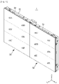
- FIG. 1 is a perspective view of a display apparatus according to an embodiment of the present disclosure.
- "X" represents a front-rear direction of the display apparatus
- "Y” represents a left-right direction of the display apparatus
- "Z” represents a up-down direction of the display apparatus.
- a display apparatus 1 which is an apparatus for displaying information and data as characters, figures, graphs, images, etc., may be a television (TV), a personal computer (PC), a mobile device, a digital signage, etc.
- the display apparatus 1 may be installed on a ground by a stand (not shown) or on a wall.
- the display apparatus 1 may include a main frame 10 (e.g. a cabinet), and a plurality of Light Emitting Diode (LED) module assemblies 20 and 30 installed on the main frame 10.
- Each of the plurality of LED module assemblies 20 and 30 may include a support frame 50 positioned on the main frame 10, and a plurality of LED modules 40A to 40L installed on the support frame 50.
- any one LED module assembly of the plurality of LED module assemblies 20 and 30 may include a plurality of LED modules 40A to 40F, and the other LED module assembly of the plurality of LED module assemblies 20 and 30 may include a plurality of LED modules 40G to 40L.
- the LED module assembly 20 may include the plurality of LED modules 40A to 40F
- the LED module assembly 30 may include the plurality of LED modules 40G to 40L.
- the main frame 10 may form a part of an outer appearance of the display apparatus 1.
- the main frame 10 may include a main frame body 11 (see FIG. 2 ) forming a rear outer appearance of the display apparatus 1, and an edge portion 12 (see FIG. 2 ) extending from the main frame body 11 in a front direction of the display apparatus 1.
- the plurality of LED modules 40A to 40L installed on the support frame 50 may implement a screen of the display apparatus 1.
- the plurality of LED modules 40A to 40L may be arranged in the form of a M*N matrix in up, down, left, and right directions to be adjacent to each other.
- 12 LED modules 40A to 40L may be installed in the form of a 3*4 matrix on the support frame 50.
- the number and arrangement of the LED modules 40A to 40L are not limited to this example, and may change variously.
- the plurality of LED modules 40A to 40L may be installed on two support frames 50.
- a part 40A to 40F of the plurality of LED modules 40A to 40L may be installed on the support frame 50 of any one LED module assembly of the plurality of LED module assemblies 20 and 30, and the other part 40G to 40L may be installed on the support frame 50 of the other LED module assembly of the plurality of LED module assemblies 20 and 30.
- the part 40A to 40F of the plurality of LED modules 40A to 40L may be installed on the support frame 50 of the LED module assembly 20, and the other part 40G to 40L may be installed on the support frame 50 of the LED module assembly 30.
- the number of the support frames 50 is not limited to this example, and may change variously.
- each support frame 50 may be positioned on the main frame 10 and exposed to the outside.
- the edge portion 52 of the support frame 50 may form upper, lower, and side appearances of the display apparatus 1, together with the edge portion 12 of the main frame 10.
- the support frame 50 may be positioned on the main frame 10 and exposed to the outside of the display apparatus 1.
- the support frame 50 may be positioned on the main frame 10 without being exposed to the outside of the display apparatus 1.
- the plurality of LED modules 40A to 40L may have a flat shape or a curved shape. Also, the curvature of the plurality of LED modules 40A to 40L may change.
- FIG. 2 is a perspective view of a display apparatus according to an embodiment of the present disclosure, when a LED module assembly is separated from a main frame.
- the plurality of LED module assemblies 20 and 30 may be separated from the main frame 10. In other words, the plurality of LED module assemblies 20 and 30 may be detachably coupled with the main frame 10.
- the display apparatus 1 may further include a magnet 60 (see FIG. 7C ) movably positioned on the main frame 10.
- the plurality of LED module assemblies 20 and 30 may be detachably coupled with the main frame 10 by a magnetic force (e.g. a magnetically attractive force). More specifically, the plurality of LED module assemblies 20 and 30 may be detachably coupled with the main frame 10 by an interaction between a magnetic material 55 positioned on the plurality of LED module assemblies 20 and 30 and the magnet 60 positioned on the main frame 10.
- the magnet 60 positioned on the main frame 10 may be movably accommodated in a magnet accommodating boss 15 of the main frame 10. More specifically, the magnet 60 may be accommodated in the magnet accommodating boss 15 of the main frame 10 in such a way to be movable in the front-rear direction X of the display apparatus 1.
- the plurality of LED module assemblies 20 and 30 may be coupled with the main frame 10. Meanwhile, when the magnet 60 moves away from the magnetic material 55 positioned on the plurality of LED module assemblies 20 and 30 to be separated from the magnetic material 55, the plurality of LED module assemblies 20 and 30 may be separated from the main frame 10.
- the plurality of LED module assemblies 20 and 30 may be coupled with the main frame 10. Meanwhile, when the magnet 60 moves in a rear direction of the display apparatus 1 to move away from the magnetic material 55 positioned on the plurality of LED module assemblies 20 and 30, the plurality of LED module assemblies 20 and 30 may be separated from the main frame 10.
- the magnet accommodating boss 15 may be provided.
- a plurality of magnetic accommodating bosses 15 may be provided in the main frame 10.
- the magnet accommodating bosses 15 may be positioned on the edge portion 12 of the main frame 10 towards the front direction of the display apparatus 1.
- Each magnet accommodating boss 15 may extend in the front-rear direction X of the display apparatus 1 such that the magnet 60 can move in the front-rear direction of the display apparatus 1 in the inside of the magnetic accommodating boss 15.
- the magnet accommodating boss 15 may extend towards the LED module assemblies 20 and 30 with a predetermined length in the front-rear direction X of the display apparatus 1.
- the magnet accommodating boss 15 may be installed on the edge portion 12 of the main frame 10, as a component that is separated from the main frame 10. However, the magnet accommodating boss 15 may be integrated into the main frame 10. When the magnet accommodating boss 15 is integrated into the main frame 10, the magnet accommodating boss 15 may extend towards the LED module assemblies 20 and 30 from the edge portion 12 of the main frame 10.
- a cover 70 may be detachably coupled with the main frame 10 to facilitate access to a power cable 80.
- the cover 70 may be detachably coupled with the main frame body 11 to facilitate an access to the power cable 80 located behind the main frame 10. The cover 70 will be described in more detail, later.
- the display apparatus 1 may further include an accommodating space 18 defined by the main frame 10 and the plurality of LED module assemblies 20 and 30 detachably coupled with the main frame 10.
- the accommodating space 18 may be formed between the main frame 10 and the plurality of LED module assemblies 20 and 30 detachably coupled with the main frame 10.
- the display apparatus 1 may further include a control board 90 for driving the plurality of LED modules 40A to 40L.
- the control board 90 may be positioned in the accommodating space 18. When the control board 90 needs to be repaired or inspected, a repairer or inspector may easily access the control board 90 by separating the plurality of LED module assemblies 20 and 30 from the main frame 10 without having to disassemble the entire of the display apparatus 1.
- FIG. 3 is an exploded perspective view of a LED module assembly of a display apparatus according to an embodiment of the present disclosure
- FIG. 4 is a rear view of a LED module assembly of a display apparatus according to an embodiment of the present disclosure
- FIG. 5A is a front perspective view of a support frame of a LED module assembly in a display apparatus according to an embodiment of the present disclosure
- FIG. 5B is a rear perspective view of a support frame of a LED module assembly in a display apparatus according to an embodiment of the present disclosure.
- the plurality of LED modules 40A to 40F may be installed on the LED module assembly 20, and the plurality of LED module assembly 20 may include the support frame 50 including the magnetic material 55 that interacts with the magnet 60 accommodated in the inside of the magnet accommodating boss 15. It is understood, based on FIGS. 3 to 5B , that the plurality of LED modules 40A to 40L may be installed on the plurality of LED module assemblies 20 and 30, and each of the plurality of LED module assemblies 20 and 30 may include the support frame 50 including the magnetic material 55 that interacts with the magnet 60 accommodated in the inside of the magnet accommodating boss 15.
- Each of the plurality of LED module assemblies 20 and 30 may further include a coupling member 100 for coupling the plurality of LED modules 40A to 40L with the support frame 50.
- the coupling member 100 may be a double-sided tape.
- the coupling member 100 is not limited to a double-sided tape.
- the coupling member 100 may be positioned between the plurality of LED modules 40A to 40L and the support frame 50 to couple the plurality of LED modules 40A to 40L with the support frame 50.
- Each of the plurality of LED modules 40A to 40L may include a first surface 41 (see FIG. 2 ) forming a screen of the display apparatus 1, and a second surface 42 that is opposite to the first surface 41 and faces the support frame 50.
- the plurality of LED modules 40A to 40L may further include a protrusion 45 formed on one surface of the plurality of LED modules 40A to 40L facing the support frame 50.
- the plurality of LED modules 40A to 40L may include the protrusion 45 formed on the second surface 42 of the plurality of LED modules 40A to 40L.
- the protrusion 45 may be formed on the second surface 42 of at least one of the plurality of LED modules 40A to 40L.
- the protrusion 45 of the plurality of LED modules 40A to 40L may be inserted in an insertion hole 56 of the support frame 50.
- the protrusion 45 may be made of metal.
- six protrusions 45 may be formed on one surface of each LED module 40A to 40L. However, the number of the protrusions 45 is not limited to the example, and may change variously.
- the plurality of LED modules 40A to 40L may be electrically connected to the control board 90.
- the plurality of LED modules 40A to 40L may further include a connector 47 formed on the second surfaces 42 to be electrically connected to the control board 90.
- the support frame 50 may include a support frame body 51, and the edge portion 52 extending from the support frame body 51 towards the rear direction of the display apparatus 1.
- the support frame 50 may include a first surface 53 facing the plurality of LED modules 40A to 40L, and a second surface 54 that is opposite to the first surface 53 and faces the main frame body 11.
- the plurality of LED modules 40A to 40L may be bonded or coupled on the first surface 53 of the support frame 50 by the coupling member 100.
- the first surface 53 of the support frame 50 may be a front surface of the support frame 50.
- the support frame 50 may further include a magnetic material coupling portion 58 with which the magnetic material 55 is coupled.
- the magnetic material 55 may be coupled with the magnetic material coupling portion 58 of the support frame 50.
- the magnetic material coupling portion 58 may be formed at a corner of the support frame 50.
- the magnetic material 55 may be coupled with the magnetic material coupling portion 58 such that one end of the magnetic material 55 faces the plurality of LED modules 40A to 40L and the other end of the magnetic material 55 interacts with the magnet 60 positioned on the main frame 10.
- the support frame 50 may further include the insertion hole 56 in which the protrusion 45 of the plurality of LED modules 40A to 40L is inserted.
- the insertion hole 56 may be formed in the support frame body 51.
- a thread 56a in an inner circumferential surface of the insertion hole 56, a thread 56a (see FIG. 9B ) may be formed.
- the number and location of the insertion hole 56 may correspond to the number and location of the protrusion 45.
- the display apparatus 1 may further include a power cable 80 (see FIG. 7C ) for supplying power to the plurality of LED modules 40A to 40L.
- the power cable 80 may be connected to a power supply (not shown) to supply power to the plurality of LED modules 40A to 40L.
- the power cable 80 may be located behind the display apparatus 1. In other words, the power cable 80 may be located behind the main frame 10.
- the display apparatus 1 may further include the cover 70 (see FIG. 2 ) installed in the main frame 10 to facilitate a connection of the power cable 80 .
- the cover 70 may be detachably installed in the main frame 10.
- an opening 11a (see FIG. 7D ) may be formed to correspond to the power cable 80, and the cover 70 may be installed in the main frame body 11 to open or close the opening 11a.
- the cover 70 may include an operating portion 71 (see FIG. 7E ) and a coupling groove 72 (see FIG. 7E ). More specifically, the operating portion 71 may be formed on one side of the cover 70 in such a way to be elastically deformable, and the coupling groove 72 may be formed on the other side of the cover 70.
- a locking portion 11b (see FIG.
- the cover 70 When the operating portion 71 of the cover 70 is pressed in an inward direction of the cover 70 to be spaced from the locking portion 11b of the main frame body 11, and the holding portion 11c of the main frame body 11 is separated from the coupling groove 72 of the cover 70, the cover 70 may be separated from the main frame body 11 so that the opening 11a of the main frame body 11 may be maintained in an open state.
- the opening 11a is formed in the main frame body 11 and the cover 70 for opening or closing the opening 11a is provided, access to the power cable 80 is possible without having to separate the display apparatus 1 from the installation surface to disassemble the display apparatus 1. Also, by forming a slit in the cover 70, foreign materials may be prevented from entering the accommodating space 18, and also heat generated from the control board 90, etc. may be discharged to the outside of the display apparatus 1 through the slit formed in the cover 70.
- the cover 70 may have another structure as long as it can open or close the opening 11a to allow an access to the power cable 80.
- the cover 70 may be rotatably installed in the main frame body 11 to open or close the opening 11a.
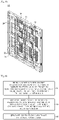
- FIG. 6 is a block diagram for describing a process of disassembling a display apparatus according to an embodiment of the present disclosure to connect or disconnect a power cable of the display apparatus
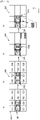
- FIGS. 7A to 7E show a process of disassembling a display apparatus according to an embodiment of the present disclosure to connect or disconnect a power cable of the display apparatus.
- a method of disassembling a display apparatus may include operation S1 of bringing a magnet member having ferromagnetism close to LED module assemblies attached to a main frame to move a magnet positioned on the main frame away from a magnetic material positioned on the LED module assemblies.
- the method of disassembling the display apparatus may further include operation S2 of separating, when the magnetic material positioned on the LED module assemblies is separated from the magnet positioned on the main frame, the LED module assemblies from the main frame.
- the method of disassembling the display apparatus may further include operation S3 of separating a cover from the main frame to access a power cable.
- Operation S3 of separating the cover from the main frame may include operation of pressing an operating portion formed in one side of the cover in an inward direction of the cover to separate the cover from a locking portion formed in the main frame.
- Operation S3 of separating the cover from the main frame may further include operation of separating the other side of the cover from a holding portion formed in the main frame to completely separate the cover from the main frame.
- a magnet member 200 having ferromagnetism may be brought close to the LED module assembly 20.
- the magnet member 200 may have stronger magnetism than the magnet 60 positioned on the main frame 10.
- a repulsive force may act between the magnet member 200 and the magnet 60 positioned on the main frame 10 so that the magnet 60 may be separated from the magnetic material 55. That is, the magnet 60 may move towards the rear direction of the display apparatus 1 by the repulsive force acting between the magnet member 200 and the magnet 60, and accordingly, coupling between the magnetic material 55 and the magnet 60 may be released.
- the LED module assembly 20 may be separated from the main frame 10, as shown in FIG. 7B .
- the LED module assembly 20 is separated from the main frame 10, as shown in FIG. 7B , access to the accommodating space 18 is possible so that the control board 90, etc. located in the accommodating space 18 may be easily repaired or inspected.
- the cover 70 may be installed in the main frame body 11 to close the opening 11a formed in the main frame body 11. To access the power cable 80 behind the main frame 10, the cover 70 may need to be separated from the main frame body 11.
- the operating portion 71 of the cover 70 when the operating portion 71 of the cover 70 is pressed toward the inward direction of the cover 70, the operating portion 71 of the cover 70 may be separated from the locking portion 11b provided in the main frame body 11 so that one side of the cover 70 is separated from the main frame body 11.
- the coupling groove 72 of the cover 70 is decoupled from the holding portion 11c provided in the main frame body 11 in the state in which one side of the cover 70 is separated from the main frame body 11, the cover 70 may be completely separated from the main frame body 11, as shown in FIG. 7E .
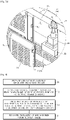
- FIG. 8 is a block diagram for describing a process of disassembling a display apparatus according to an embodiment of the present disclosure to separate a plurality of LED modules of the display apparatus from a support frame
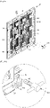
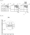
- FIG. 9A shows a process of disassembling a display apparatus according to an embodiment of the present disclosure to separate a plurality of LED modules of the display apparatus from a support frame
- FIG. 9B is an enlarged view of an area of FIG. 9A .
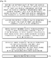
- a method of disassembling a display apparatus may include operation T1 of preparing a LED module assembly separated from a main frame.
- the method of disassembling the display apparatus may further include operation T2 of locating the LED module assembly separated from the main frame such that a second surface of a support frame is shown, wherein the second surface of the support frame may be a rear surface of the support frame.
- the method of disassembling the display apparatus may further include operation T3 of pressing a protrusion of a plurality of LED modules, which is inserted in an insertion hole of the support frame, at the second surface of the support frame, by using a pressing device.
- Operation T3 of pressing the protrusion of the plurality of LED modules by using the pressing device may include operation of rotating the pressing device in the state in which a first thread of the pressing device is engaged with a second thread formed in an inner circumferential surface of the insertion hole to thereby press the protrusion of the plurality of LED modules.
- the plurality of LED modules may be separated from the support frame by pressing the protrusion of the plurality of LED modules with a greater force than a coupling force of the coupling member by using the pressing device.
- the method of disassembling the display apparatus may include operation T4 of separating the plurality of LED modules from the support frame.
- the LED module assembly 20 separated from the main frame 10 may be located such that the second surface 54 of the support frame 50 is shown. In other words, the LED module assembly 20 separated from the main frame 10 may be turned over such that the second surface 54 of the support frame 50 is shown.
- a user may press the protrusion 45 of the plurality of LED modules 40A to 40L, inserted in the insertion hole 56 of the support frame 50, by using a pressing device 300.
- the pressing device 300 may be a jig. However, the kind of the pressing device 300 is not limited to a jig as long as it can press the protrusion 45 of the plurality of LED modules 40A to 40L.
- the pressing device 300 may include a first thread 310.
- the second thread 56a may be formed to correspond to the first thread 310 of the pressing device 300.
- the user may couple the pressing device 300 with the insertion hole 56 of the support frame 50, and then rotate the pressing device 300 in the state in which the first thread 310 of the pressing device 300 is engaged with the second thread 56a of the insertion hole 56, thereby pressing the protrusion 45 of the plurality of LED modules 40A to 40F.
- the plurality of LED modules 40A to 40F may be separated from the support frame 50 by a pressing force of the pressing device 300.
- FIG. 10 is a block diagram for describing a process of disassembling a display apparatus according to another embodiment of the present disclosure to separate any one of a plurality of LED module assemblies from a main frame.
- the same components as those described above with reference to FIGS. 1 to 9B will be assigned the same reference numerals as those assigned to the corresponding components of FIGS. 1 to 9B .
- descriptions overlapping with the above descriptions given with reference to FIGS. 1 to 9B will be omitted.
- a method of disassembling a display apparatus may include operation P1 of securing a gap between each of a first LED module assembly that is to be separated among a plurality of first LED module assemblies, another first LED module assembly neighboring the first LED module assembly that is to be separated, among the plurality of first LED module assemblies, and a plurality of second LED module assemblies.
- the method of disassembling the display apparatus may further include operation P2 of locating a protection cover in the gap to surround at least one part of the first LED module assembly that is to be separated.
- Operation P2 of locating the protection cover in the gap may include operation of detachably coupling the protection cover with the other first LED module assembly neighboring the at least one part of the first LED module assembly that is to be separated, and the plurality of second LED module assemblies.
- Operation P2 of locating the protection cover in the gap may include operation of coupling the protection cover with the other first LED module assembly, neighboring the at least one part of the first LED module assembly that is to be separated, and the plurality of second LED module assemblies by using a magnetic force.
- Operation of coupling the protection cover with the other first LED module assembly, neighboring the at least one part of the first LED module assembly that is to be separated, and the plurality of second LED module assemblies may include operation of coupling a magnet of the protection cover with the protrusion of the other first LED module assembly and coupling the magnet of the protection cover with the protrusion of the plurality of second LED module assemblies to couple the protection cover with the other first LED module assembly and the plurality of second LED module assemblies such that the protection cover covers at least one part of the other first LED module assembly and at least one part of the plurality of second LED module assemblies.
- the method of dissembling the display apparatus may further include operation of separating the first LED module assembly that is to be separated, from a first main frame.
- the method of disassembling the display apparatus may include operation P3 of bringing a magnet member having ferromagnetism close to the first LED module assembly that is to be separated, to move a magnet positioned on the first main frame away from a magnetic material positioned on the first LED module assembly that is to be separated.
- the method of disassembling the display apparatus may further include operation P4 of separating, when the magnetic material positioned on the first LED module assembly that is to be separated is separated from the magnet positioned on the first main frame, the first LED module assembly that is to be separated from the first main frame.
- the method of disassembling the display apparatus may further include operation P5 of removing the protection cover.
- the protection cover may be removed from the gap after the first LED module assembly that is to be separated is separated from the first main frame or after the first LED module assembly is separated and then replaced with a new first LED module assembly.
- FIG. 11 schematically shows a process of disassembling the display apparatus of FIG. 10
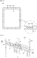
- FIG. 12 shows a protection cover used in a process of disassembling the display apparatus of FIG. 10
- FIG. 13 shows a coupling structure between the protection cover of FIG. 12 and a plurality of LED module assemblies neighboring a LED module assembly that is to be separated.
- a display apparatus 1a may include a plurality of units.
- the plurality of units may be arranged in the form of a M*N matrix to be adjacent to each other.
- 6 units may be arranged in the form of a 3*2 matrix.
- an arrangement of the plurality of units is not limited the example, and may change variously.
- Each unit may include a main frame and a plurality of LED module assemblies positioned on the main frame.
- each unit may include a main frame and two LED module assemblies positioned on the main frame.
- the display apparatus 1a is assumed to include a first unit 500 and a plurality of second units 600 neighboring the first unit 500.
- the first unit 500 may include a first main frame 530 and a plurality of first LED module assemblies 510 and 520 positioned on the first main frame 530.
- the second unit 600 may include a second main frame and a plurality of second LED module assemblies 610 and 620 positioned on the second main frame.
- a protection cover 1000 may be used to prevent the first LED module assembly 520 and LED module assemblies located around the first LED module assembly 520 from being damaged.
- the protection cover 1000 may include a cavity 1010 and a plurality of edge portions 1020 defining the cavity 1010.
- the plurality of edge portions 1020 may be connected to each other.
- the plurality of edge portions 1020 may be connected to each other to form a closed loop.
- the protection cover 1000 may have a shape corresponding to the first LED module assembly 520 that is to be separated.
- the protection cover 1000 may include the cavity 1010 and four edge portions 1020 defining the cavity 1010. That is, the protection cover 1000 may be in the shape of a rectangle having the cavity 1010.
- the first LED module assembly 520 that is to be separated may be coupled with the cavity 1010 of the protection cover 1000.
- the first LED module assembly 520 that is to be separated may be coupled with the cavity 1010 of the protection cover 1000 to be positioned in the inside of the cavity 1010 of the protection cover 1000.
- the plurality of edge portions 1020 of the protection cover 1000 may cover the plurality of LED module assemblies 510, 610, and 620 neighboring the first LED module assembly 520 that is to be separated. More specifically, the plurality of edge portions 1020 of the protection cover 1000 may cover at least one part of the plurality of LED module assemblies 510, 610, and 620 surrounding the first LED module assembly 520 that is to be separated.
- the protection cover 1000 may be made of a plastic material. However, a material forming the protection cover 1000 is not limited to plastic, and the protection cover 1000 may be made of another material.
- the protection cover 1000 may further include a magnet 1030.
- the magnet 1030 of the protection cover 1000 may be positioned on a surface of the protection cover 1000, the surface facing the plurality of LED module assemblies 510, 610, and 620 neighboring the first LED module assembly 520 that is to be separated.
- the magnet 1030 of the protection cover 1000 may be positioned on one surface of the plurality of edge portions 1020, the surface facing the plurality of LED module assemblies 510, 610, and 620 neighboring the first LED module assembly 520 that is to be separated.
- the protection cover 1000 may further include a plurality of magnet accommodating portions 1040 formed in the plurality of edge portions 1020 such that the magnet 1030 is rested in each magnet accommodating portion 1040.
- the magnet 1030 of the protection cover 1000 may be accommodated in each magnet accommodating portion 1040 such that one surface of the magnet 1030 is exposed.
- the magnet 1030 of the protection cover 1000 may interact with the protrusion 45 provided in the plurality of LED module assemblies 510, 610, and 620 neighboring the first LED module assembly 520 that is to be separated, by a magnetic force.
- the protrusion 45 may include metal reacting to the magnet 1030.
- the magnet 1030 of the protection cover 1000 may be detachably coupled with the protrusion 45 of the plurality of LED module assemblies 510, 610, and 620 neighboring the first LED module assembly 520 that is to be separated, with the plurality of LED modules 40A to 40L of the plurality of LED module assemblies 510, 610, and 620 in between.
- a gap between each of the first LED module assembly 520, the other first LED module assembly 510 neighboring the first LED module assembly 520, and the plurality of second LED module assemblies 610 and 620 of the second unit 600 may need to be secured.
- the gap may be about 0.5 mm.
- the LED module assemblies 510, 610, and 620 located around the first LED module assembly 520 that is to be separated may be moved to be spaced about 2 mm from the first LED module assembly 520.
- the protection cover 1000 may be positioned in the gap such that the first LED module assembly 520 that is to be separated is inserted in the cavity 1010 of the protection cover 1000.
- the plurality of edge portions 1020 of the protection cover 1000 may be coupled with the LED module assemblies 510, 610, and 620 located around the first LED module assembly 520 that is to be separated, to cover the LED module assemblies 510, 610, and 620 that may contact the first LED module assembly 520 when the first LED module assembly 520 is separated from the first main frame 530.
- a part of the protection cover 1000 may be positioned between the first LED module assembly 520 that is to be separated and the LED module assemblies 510, 610, and 620 located around the first LED module assembly 520, and the other part of the protection cover 1000 may be coupled with the LED module assemblies 510, 610, and 620 located around the first LED module assembly 520 by a magnetic force.
- the first LED module assembly 520 among the plurality of first LED module assemblies 510 and 520 of the first unit 500 may be separated from the first main frame 530 of the first unit 500 without damaging the neighboring LED module assemblies 510, 610, and 620, by the protection cover 1000.
- the protection cover 1000 may be removed from the neighboring LED module assemblies 510, 610, and 620, after the separated first LED module assembly 520 is inspected or repaired and then located at its original position or after the first LED module assembly 520 is replaced with a new LED module assembly.
- the plurality of first LED module assemblies 510 and 520 of the first unit 500 and the plurality of second LED module assemblies 610 and 620 of the second unit 600 may be assembled to their original states without making any gap in between.
- FIG. 14 schematically shows a process of separating any one of a plurality of LED module assemblies of a display apparatus according to another embodiment of the present disclosure from a main frame by using a protection cover that is different from the protection cover shown in FIG. 12
- FIG. 15 is an enlarged view of the protection cover shown in FIG. 14 .
- a protection cover 1000a may include two edge portions 1020.
- the two edge portions 1020 may be connected to each other.
- the protection cover 1000a may be used when the first LED module assembly 520 that is to be separated is located at a corner of the display apparatus 1a, in other words, when the first LED module assembly 520 that is to be separated neighbors two LED module assemblies 510 and 620.
- a gap between each of the first LED module assembly 520, the other first LED module assembly 510 neighboring the first LED module assembly 520, and the plurality of second LED module assemblies 610 and 620 of the second unit 600 may need to be secured.
- the protection cover 1000a may be put in the gap.
- any one of the plurality of edge portions 1020 of the protection cover 1000a may be coupled with the other first LED module assembly 510 of the plurality of first LED module assemblies 510 and 520 of the first unit 500 to cover at least one part of the other first LED module assembly 510
- the other one of the plurality of edge portions 1020 of the protection cover 1000a may be coupled with any one LED module assembly of the plurality of LED modules 610 and 620 of the second unit 600 to cover at least one part of the LED module assembly.
- the protection cover 1000a may be coupled with the LED module assembly 620 to cover at least one part of the LED module assembly 620.
- the protection cover 1000a may be detachably coupled with the plurality of LED module assemblies 510 and 620 located around the first LED module assembly 520 that is to be separated, by a magnetic force.
- the first LED module assembly 520 among the plurality of first LED module assemblies 510 and 520 of the first unit 500 may be separated from the first main frame 530 of the first unit 500 without damaging the neighboring LED module assemblies 510 and 620, by the protection cover 1000a.
- the protection cover 1000a may be removed from the neighboring LED module assemblies 510 and 620, after the separated first LED module assembly 520 is inspected or repaired and then located at its original position or after the first LED module assembly 520 is replaced with a new LED module assembly.
- the plurality of first LED module assemblies 510 and 520 of the first unit 500 and the plurality of second LED module assemblies 610 and 620 of the second unit 600 may be assembled to their original states without making any gap in between.
Landscapes
- Engineering & Computer Science (AREA)
- Physics & Mathematics (AREA)
- General Physics & Mathematics (AREA)
- Theoretical Computer Science (AREA)
- Multimedia (AREA)
- Microelectronics & Electronic Packaging (AREA)
- Nonlinear Science (AREA)
- Devices For Indicating Variable Information By Combining Individual Elements (AREA)
- General Engineering & Computer Science (AREA)
- Mechanical Engineering (AREA)
- Mathematical Physics (AREA)
- Chemical & Material Sciences (AREA)
- Crystallography & Structural Chemistry (AREA)
- Human Computer Interaction (AREA)
- Optics & Photonics (AREA)
- Casings For Electric Apparatus (AREA)
Description
- The present disclosure relates to a display apparatus and a disassembling method thereof, and more particularly, to a display apparatus having an improved structure that can be easily disassembled upon repair or inspection, and a method of disassembling the display apparatus.
- A display apparatus is a kind of output apparatus that visually displays images and data information, such as characters, figures, etc. Recently, needs for high brightness, high resolution, a large-screen, high efficiency, and low power of display apparatuses are increasing more and more. Accordingly, as a new display apparatus which will replace the Light Crystal Display (LCD) panel, an Organic Light Emitting Diode (OLED) panel is spotlighted. However, the OLED panel still has many problems that have to be solved, such as high price due to low yield, securing reliability according to enlargement, and securing durability against external environmental conditions such as water.
- As a new product that can replace or complement the LCD and OLED panels, a panel manufactured by mounting inorganic light emitting devices of emitting light of Red (R), Green (G), and Blue (B) colors directly on a board is being studied.
- When a display apparatus installed on an installation surface needs to be disassembled by reason of inspection or repair, a work of separating the display apparatus from the installation surface should be first performed. However, when the display apparatus is separated from the installation surface or when the display apparatus is disassembled for inspection or repair, the display apparatus may be damaged.
- As background art,
WO 2016/208918 A1 describes a display module, a display device and a method of assembling and disassembling the display module. - Additional aspects of the disclosure will be set forth in part in the description which follows and, in part, will be obvious from the description, or may be learned by practice of the disclosure.
- There is provided a display apparatus in accordance with
claim 1, a method of disassembling the display apparatus ofclaim 1 in accordance with claim 8 and a method of disassembling the display apparatus ofclaim 1 in accordance withclaim 15. - Because coupling between the magnet positioned in the main frame and the magnetic material positioned in the LED module assembly can be released by using the magnet member having ferromagnetism, there is no need to separate the display apparatus from the installation surface and completely disassemble the display apparatus when the control board, etc. positioned in the accommodating space are inspected or repaired.
- By installing the detachable cover in the main frame, it may be possible to facilitate access to the power cable.
- By using the removable protection cover when the LED module assembly is separated, it may be possible to prevent the LED module assembly and LED module assemblies located around the LED module assembly from being damaged.
- These and/or other aspects of the disclosure will become apparent and more readily appreciated from the following description of the embodiments, taken in conjunction with the accompanying drawings of which:
-
FIG. 1 is a perspective view of a display apparatus according to an embodiment of the present disclosure; -
FIG. 2 is a perspective view of a display apparatus according to an embodiment of the present disclosure, when a Light Emitting Diode (LED) module assembly is separated from a main frame; -
FIG. 3 is an exploded perspective view of a LED module assembly of a display apparatus according to an embodiment of the present disclosure; -
FIG. 4 is a rear view of a LED module assembly of a display apparatus according to an embodiment of the present disclosure; -
FIG. 5A is a front perspective view of a support frame of a LED module assembly in a display apparatus according to an embodiment of the present disclosure; -
FIG. 5B is a rear perspective view of a support frame of a LED module assembly in a display apparatus according to an embodiment of the present disclosure; -
FIG. 6 is a block diagram for describing a process of disassembling a display apparatus according to an embodiment of the present disclosure to connect or disconnect a power cable of the display apparatus; -
FIGS. 7A to 7E show a process of disassembling a display apparatus according to an embodiment of the present disclosure to connect or disconnect a power cable of the display apparatus; -
FIG. 8 is a block diagram for describing a process of disassembling a display apparatus according to an embodiment of the present disclosure to separate a plurality of LED modules of the display apparatus from a support frame; -
FIG. 9A shows a process of disassembling a display apparatus according to an embodiment of the present disclosure to separate a plurality of LED modules of the display apparatus from a support frame; -
FIG. 9B is an enlarged view of an area ofFIG. 9A ; -
FIG. 10 is a block diagram for describing a process of disassembling a display apparatus according to another embodiment of the present disclosure to separate any one of a plurality of LED module assemblies from a main frame; -
FIG. 11 schematically shows a process of disassembling the display apparatus ofFIG. 10 ; -
FIG. 12 shows a protection cover used in a process of disassembling the display apparatus ofFIG. 10 ; -
FIG. 13 shows a coupling structure between the protection cover ofFIG. 12 and a plurality of LED module assemblies neighboring a LED module assembly that is to be separated; -
FIG. 14 schematically shows a process of separating any one of a plurality of LED module assemblies of a display apparatus according to another embodiment of the present disclosure from a main frame by using a protection cover that is different from the protection cover shown inFIG. 12 ; and -
FIG. 15 is an enlarged view of the protection cover shown inFIG. 14 . - Hereinafter, embodiments of the present disclosure will be described in detail with reference to the accompanying drawings. In the following description, the terms "front end", "rear end", "upper portion", "lower portion", "upper end", and "lower end", when used in this specification, are defined based on the drawings, and the shapes and locations of the corresponding components are not limited by the terms.
-
FIG. 1 is a perspective view of a display apparatus according to an embodiment of the present disclosure. InFIG. 1 , "X" represents a front-rear direction of the display apparatus, "Y" represents a left-right direction of the display apparatus, and "Z" represents a up-down direction of the display apparatus. - As shown in
FIG. 1 , adisplay apparatus 1, which is an apparatus for displaying information and data as characters, figures, graphs, images, etc., may be a television (TV), a personal computer (PC), a mobile device, a digital signage, etc. Thedisplay apparatus 1 may be installed on a ground by a stand (not shown) or on a wall. - The
display apparatus 1 may include a main frame 10 (e.g. a cabinet), and a plurality of Light Emitting Diode (LED)module assemblies main frame 10. Each of the plurality of LED module assemblies 20 and 30 may include asupport frame 50 positioned on themain frame 10, and a plurality ofLED modules 40A to 40L installed on thesupport frame 50. More specifically, any one LED module assembly of the plurality ofLED module assemblies LED modules 40A to 40F, and the other LED module assembly of the plurality ofLED module assemblies LED modules 40G to 40L. For example, in an embodiment of the present disclosure, theLED module assembly 20 may include the plurality ofLED modules 40A to 40F, and theLED module assembly 30 may include the plurality ofLED modules 40G to 40L. - The
main frame 10 may form a part of an outer appearance of thedisplay apparatus 1. Themain frame 10 may include a main frame body 11 (seeFIG. 2 ) forming a rear outer appearance of thedisplay apparatus 1, and an edge portion 12 (seeFIG. 2 ) extending from themain frame body 11 in a front direction of thedisplay apparatus 1. The plurality ofLED modules 40A to 40L installed on thesupport frame 50 may implement a screen of thedisplay apparatus 1. - The plurality of
LED modules 40A to 40L may be arranged in the form of a M*N matrix in up, down, left, and right directions to be adjacent to each other. In the current embodiment, 12LED modules 40A to 40L may be installed in the form of a 3*4 matrix on thesupport frame 50. However, the number and arrangement of theLED modules 40A to 40L are not limited to this example, and may change variously. In the current embodiment, the plurality ofLED modules 40A to 40L may be installed on twosupport frames 50. More specifically, apart 40A to 40F of the plurality ofLED modules 40A to 40L may be installed on thesupport frame 50 of any one LED module assembly of the plurality ofLED module assemblies other part 40G to 40L may be installed on thesupport frame 50 of the other LED module assembly of the plurality ofLED module assemblies part 40A to 40F of the plurality ofLED modules 40A to 40L may be installed on thesupport frame 50 of theLED module assembly 20, and theother part 40G to 40L may be installed on thesupport frame 50 of theLED module assembly 30. However, the number of thesupport frames 50 is not limited to this example, and may change variously. - An edge portion 52 (see
FIG. 2 ) of eachsupport frame 50 may be positioned on themain frame 10 and exposed to the outside. Theedge portion 52 of thesupport frame 50 may form upper, lower, and side appearances of thedisplay apparatus 1, together with theedge portion 12 of themain frame 10. In the current embodiment, thesupport frame 50 may be positioned on themain frame 10 and exposed to the outside of thedisplay apparatus 1. However, thesupport frame 50 may be positioned on themain frame 10 without being exposed to the outside of thedisplay apparatus 1. - The plurality of
LED modules 40A to 40L may have a flat shape or a curved shape. Also, the curvature of the plurality ofLED modules 40A to 40L may change. -
FIG. 2 is a perspective view of a display apparatus according to an embodiment of the present disclosure, when a LED module assembly is separated from a main frame. - As shown in
FIG. 2 , the plurality ofLED module assemblies main frame 10. In other words, the plurality ofLED module assemblies main frame 10. - The
display apparatus 1 may further include a magnet 60 (seeFIG. 7C ) movably positioned on themain frame 10. The plurality ofLED module assemblies main frame 10 by a magnetic force (e.g. a magnetically attractive force). More specifically, the plurality ofLED module assemblies main frame 10 by an interaction between amagnetic material 55 positioned on the plurality ofLED module assemblies magnet 60 positioned on themain frame 10. Themagnet 60 positioned on themain frame 10 may be movably accommodated in amagnet accommodating boss 15 of themain frame 10. More specifically, themagnet 60 may be accommodated in themagnet accommodating boss 15 of themain frame 10 in such a way to be movable in the front-rear direction X of thedisplay apparatus 1. - When the
magnet 60 moves towards themagnetic material 55 positioned on the plurality ofLED module assemblies magnetic material 55, the plurality ofLED module assemblies main frame 10. Meanwhile, when themagnet 60 moves away from themagnetic material 55 positioned on the plurality ofLED module assemblies magnetic material 55, the plurality ofLED module assemblies main frame 10. - As described from another aspect, when the
magnet 60 moves in the front direction of thedisplay apparatus 1 to move close to themagnetic material 55 positioned on the plurality ofLED module assemblies LED module assemblies main frame 10. Meanwhile, when themagnet 60 moves in a rear direction of thedisplay apparatus 1 to move away from themagnetic material 55 positioned on the plurality ofLED module assemblies LED module assemblies main frame 10. - In the
main frame 10, themagnet accommodating boss 15 may be provided. In an embodiment, in themain frame 10, a plurality of magneticaccommodating bosses 15 may be provided. Themagnet accommodating bosses 15 may be positioned on theedge portion 12 of themain frame 10 towards the front direction of thedisplay apparatus 1. Eachmagnet accommodating boss 15 may extend in the front-rear direction X of thedisplay apparatus 1 such that themagnet 60 can move in the front-rear direction of thedisplay apparatus 1 in the inside of the magneticaccommodating boss 15. In other words, themagnet accommodating boss 15 may extend towards theLED module assemblies display apparatus 1. Themagnet accommodating boss 15 may be installed on theedge portion 12 of themain frame 10, as a component that is separated from themain frame 10. However, themagnet accommodating boss 15 may be integrated into themain frame 10. When themagnet accommodating boss 15 is integrated into themain frame 10, themagnet accommodating boss 15 may extend towards theLED module assemblies edge portion 12 of themain frame 10. - A
cover 70 may be detachably coupled with themain frame 10 to facilitate access to apower cable 80. Thecover 70 may be detachably coupled with themain frame body 11 to facilitate an access to thepower cable 80 located behind themain frame 10. Thecover 70 will be described in more detail, later. - The
display apparatus 1 may further include anaccommodating space 18 defined by themain frame 10 and the plurality ofLED module assemblies main frame 10. Theaccommodating space 18 may be formed between themain frame 10 and the plurality ofLED module assemblies main frame 10. - The
display apparatus 1 may further include acontrol board 90 for driving the plurality ofLED modules 40A to 40L. Thecontrol board 90 may be positioned in theaccommodating space 18. When thecontrol board 90 needs to be repaired or inspected, a repairer or inspector may easily access thecontrol board 90 by separating the plurality ofLED module assemblies main frame 10 without having to disassemble the entire of thedisplay apparatus 1. -
FIG. 3 is an exploded perspective view of a LED module assembly of a display apparatus according to an embodiment of the present disclosure,FIG. 4 is a rear view of a LED module assembly of a display apparatus according to an embodiment of the present disclosure,FIG. 5A is a front perspective view of a support frame of a LED module assembly in a display apparatus according to an embodiment of the present disclosure, andFIG. 5B is a rear perspective view of a support frame of a LED module assembly in a display apparatus according to an embodiment of the present disclosure. - As shown in
FIGS. 3 to 5B , the plurality ofLED modules 40A to 40F may be installed on theLED module assembly 20, and the plurality ofLED module assembly 20 may include thesupport frame 50 including themagnetic material 55 that interacts with themagnet 60 accommodated in the inside of themagnet accommodating boss 15. It is understood, based onFIGS. 3 to 5B , that the plurality ofLED modules 40A to 40L may be installed on the plurality ofLED module assemblies LED module assemblies support frame 50 including themagnetic material 55 that interacts with themagnet 60 accommodated in the inside of themagnet accommodating boss 15. - Each of the plurality of
LED module assemblies coupling member 100 for coupling the plurality ofLED modules 40A to 40L with thesupport frame 50. According to an example, thecoupling member 100 may be a double-sided tape. However, thecoupling member 100 is not limited to a double-sided tape. Thecoupling member 100 may be positioned between the plurality ofLED modules 40A to 40L and thesupport frame 50 to couple the plurality ofLED modules 40A to 40L with thesupport frame 50. - Each of the plurality of
LED modules 40A to 40L may include a first surface 41 (seeFIG. 2 ) forming a screen of thedisplay apparatus 1, and asecond surface 42 that is opposite to thefirst surface 41 and faces thesupport frame 50. - The plurality of
LED modules 40A to 40L may further include aprotrusion 45 formed on one surface of the plurality ofLED modules 40A to 40L facing thesupport frame 50. In other words, the plurality ofLED modules 40A to 40L may include theprotrusion 45 formed on thesecond surface 42 of the plurality ofLED modules 40A to 40L. Theprotrusion 45 may be formed on thesecond surface 42 of at least one of the plurality ofLED modules 40A to 40L. Theprotrusion 45 of the plurality ofLED modules 40A to 40L may be inserted in aninsertion hole 56 of thesupport frame 50. For example, theprotrusion 45 may be made of metal. For example, sixprotrusions 45 may be formed on one surface of eachLED module 40A to 40L. However, the number of theprotrusions 45 is not limited to the example, and may change variously. - The plurality of
LED modules 40A to 40L may be electrically connected to thecontrol board 90. The plurality ofLED modules 40A to 40L may further include aconnector 47 formed on thesecond surfaces 42 to be electrically connected to thecontrol board 90. - The
support frame 50 may include asupport frame body 51, and theedge portion 52 extending from thesupport frame body 51 towards the rear direction of thedisplay apparatus 1. Thesupport frame 50 may include afirst surface 53 facing the plurality ofLED modules 40A to 40L, and asecond surface 54 that is opposite to thefirst surface 53 and faces themain frame body 11. The plurality ofLED modules 40A to 40L may be bonded or coupled on thefirst surface 53 of thesupport frame 50 by thecoupling member 100. Thefirst surface 53 of thesupport frame 50 may be a front surface of thesupport frame 50. - The
support frame 50 may further include a magneticmaterial coupling portion 58 with which themagnetic material 55 is coupled. Themagnetic material 55 may be coupled with the magneticmaterial coupling portion 58 of thesupport frame 50. In an embodiment of the present disclosure, the magneticmaterial coupling portion 58 may be formed at a corner of thesupport frame 50. Themagnetic material 55 may be coupled with the magneticmaterial coupling portion 58 such that one end of themagnetic material 55 faces the plurality ofLED modules 40A to 40L and the other end of themagnetic material 55 interacts with themagnet 60 positioned on themain frame 10. - The
support frame 50 may further include theinsertion hole 56 in which theprotrusion 45 of the plurality ofLED modules 40A to 40L is inserted. Theinsertion hole 56 may be formed in thesupport frame body 51. In an inner circumferential surface of theinsertion hole 56, athread 56a (seeFIG. 9B ) may be formed. The number and location of theinsertion hole 56 may correspond to the number and location of theprotrusion 45. - The
display apparatus 1 may further include a power cable 80 (seeFIG. 7C ) for supplying power to the plurality ofLED modules 40A to 40L. Thepower cable 80 may be connected to a power supply (not shown) to supply power to the plurality ofLED modules 40A to 40L. Thepower cable 80 may be located behind thedisplay apparatus 1. In other words, thepower cable 80 may be located behind themain frame 10. - The
display apparatus 1 may further include the cover 70 (seeFIG. 2 ) installed in themain frame 10 to facilitate a connection of thepower cable 80. - The
cover 70 may be detachably installed in themain frame 10. In themain frame body 11, anopening 11a (seeFIG. 7D ) may be formed to correspond to thepower cable 80, and thecover 70 may be installed in themain frame body 11 to open or close theopening 11a. Thecover 70 may include an operating portion 71 (seeFIG. 7E ) and a coupling groove 72 (seeFIG. 7E ). More specifically, the operatingportion 71 may be formed on one side of thecover 70 in such a way to be elastically deformable, and thecoupling groove 72 may be formed on the other side of thecover 70. In themain frame body 11 in which thecover 70 is installed, a lockingportion 11b (seeFIG. 7E ) interacting with the operatingportion 71 of thecover 70, and a holdingportion 11c (seeFIG. 7E ) coupled with thecoupling groove 72 of thecover 70 to hold thecover 70 may be formed. Thecover 70 may be completely separated from themain frame body 11. When the operatingportion 71 of thecover 70 is engaged with the lockingportion 11b of themain frame body 11, and the holdingportion 11c of themain frame body 11 is coupled with thecoupling groove 72 of thecover 70 to hold thecover 70, theopening 11a of themain frame body 11 may be maintained in a closed state by thecover 70. When the operatingportion 71 of thecover 70 is pressed in an inward direction of thecover 70 to be spaced from the lockingportion 11b of themain frame body 11, and the holdingportion 11c of themain frame body 11 is separated from thecoupling groove 72 of thecover 70, thecover 70 may be separated from themain frame body 11 so that theopening 11a of themain frame body 11 may be maintained in an open state. - In an embodiment, when an access to a power cable is needed, it may be necessary to separate a display apparatus from an installation surface and then dissemble the display apparatus. However, according to the current embodiment in which the
opening 11a is formed in themain frame body 11 and thecover 70 for opening or closing theopening 11a is provided, access to thepower cable 80 is possible without having to separate thedisplay apparatus 1 from the installation surface to disassemble thedisplay apparatus 1. Also, by forming a slit in thecover 70, foreign materials may be prevented from entering theaccommodating space 18, and also heat generated from thecontrol board 90, etc. may be discharged to the outside of thedisplay apparatus 1 through the slit formed in thecover 70. - In the current embodiment, a case in which the
cover 70 is completely separated from themain frame body 11 is described. However, thecover 70 may have another structure as long as it can open or close theopening 11a to allow an access to thepower cable 80. For example, thecover 70 may be rotatably installed in themain frame body 11 to open or close theopening 11a. -
FIG. 6 is a block diagram for describing a process of disassembling a display apparatus according to an embodiment of the present disclosure to connect or disconnect a power cable of the display apparatus, andFIGS. 7A to 7E show a process of disassembling a display apparatus according to an embodiment of the present disclosure to connect or disconnect a power cable of the display apparatus. - As shown in
FIG. 6 , a method of disassembling a display apparatus may include operation S1 of bringing a magnet member having ferromagnetism close to LED module assemblies attached to a main frame to move a magnet positioned on the main frame away from a magnetic material positioned on the LED module assemblies. - The method of disassembling the display apparatus may further include operation S2 of separating, when the magnetic material positioned on the LED module assemblies is separated from the magnet positioned on the main frame, the LED module assemblies from the main frame.
- The method of disassembling the display apparatus may further include operation S3 of separating a cover from the main frame to access a power cable. Operation S3 of separating the cover from the main frame may include operation of pressing an operating portion formed in one side of the cover in an inward direction of the cover to separate the cover from a locking portion formed in the main frame. Operation S3 of separating the cover from the main frame may further include operation of separating the other side of the cover from a holding portion formed in the main frame to completely separate the cover from the main frame.
- Hereinafter, a process of disassembling the
display apparatus 1 will be described with reference toFIGS. 7A to 7E . - As shown in
FIG. 7A , when any one LED module assembly of the plurality ofLED module assemblies main frame 10 by coupling between themagnet 60 positioned on themain frame 10 and themagnetic material 55 positioned on the plurality ofLED module assemblies main frame 10, amagnet member 200 having ferromagnetism may be brought close to theLED module assembly 20. Themagnet member 200 may have stronger magnetism than themagnet 60 positioned on themain frame 10. When themagnet member 200 is brought close to a location corresponding to themagnetic material 55 positioned on theLED module assembly 20 that is to be separated, a repulsive force may act between themagnet member 200 and themagnet 60 positioned on themain frame 10 so that themagnet 60 may be separated from themagnetic material 55. That is, themagnet 60 may move towards the rear direction of thedisplay apparatus 1 by the repulsive force acting between themagnet member 200 and themagnet 60, and accordingly, coupling between themagnetic material 55 and themagnet 60 may be released. - Because the coupling between the
magnet 60 positioned on themain frame 10 and themagnetic material 55 positioned on theLED module assembly 20 is released, theLED module assembly 20 may be separated from themain frame 10, as shown inFIG. 7B . When theLED module assembly 20 is separated from themain frame 10, as shown inFIG. 7B , access to theaccommodating space 18 is possible so that thecontrol board 90, etc. located in theaccommodating space 18 may be easily repaired or inspected. - As shown in
FIG. 7C , thecover 70 may be installed in themain frame body 11 to close theopening 11a formed in themain frame body 11. To access thepower cable 80 behind themain frame 10, thecover 70 may need to be separated from themain frame body 11. - As shown in
FIG. 7D , when the operatingportion 71 of thecover 70 is pressed toward the inward direction of thecover 70, the operatingportion 71 of thecover 70 may be separated from the lockingportion 11b provided in themain frame body 11 so that one side of thecover 70 is separated from themain frame body 11. When thecoupling groove 72 of thecover 70 is decoupled from the holdingportion 11c provided in themain frame body 11 in the state in which one side of thecover 70 is separated from themain frame body 11, thecover 70 may be completely separated from themain frame body 11, as shown inFIG. 7E . - As shown in
FIGS. 7A to 7E , by separating the plurality ofLED module assemblies main frame 10 without having to separate thedisplay apparatus 1 from the installation surface to easily access thecontrol board 90 located in theaccommodating space 18 and separating thecover 70 from themain frame 10 to easily access thepower cable 80, it may be possible to facilitate a process of inspecting or repairing thedisplay apparatus 1. In other words, because thedisplay apparatus 1 can be serviced from the front portion in the state in which it is installed on the installation surface, it may be unnecessary to separate thedisplay apparatus 1 from the installation surface to completely disassemble thedisplay apparatus 1 upon servicing of thedisplay apparatus 1. -
FIG. 8 is a block diagram for describing a process of disassembling a display apparatus according to an embodiment of the present disclosure to separate a plurality of LED modules of the display apparatus from a support frame, andFIG. 9A shows a process of disassembling a display apparatus according to an embodiment of the present disclosure to separate a plurality of LED modules of the display apparatus from a support frame.FIG. 9B is an enlarged view of an area ofFIG. 9A . - As shown in
FIG. 8 , a method of disassembling a display apparatus may include operation T1 of preparing a LED module assembly separated from a main frame. - The method of disassembling the display apparatus may further include operation T2 of locating the LED module assembly separated from the main frame such that a second surface of a support frame is shown, wherein the second surface of the support frame may be a rear surface of the support frame.
- The method of disassembling the display apparatus may further include operation T3 of pressing a protrusion of a plurality of LED modules, which is inserted in an insertion hole of the support frame, at the second surface of the support frame, by using a pressing device. Operation T3 of pressing the protrusion of the plurality of LED modules by using the pressing device may include operation of rotating the pressing device in the state in which a first thread of the pressing device is engaged with a second thread formed in an inner circumferential surface of the insertion hole to thereby press the protrusion of the plurality of LED modules. Because the plurality of LED modules are coupled with the support frame by a coupling member, the plurality of LED modules may be separated from the support frame by pressing the protrusion of the plurality of LED modules with a greater force than a coupling force of the coupling member by using the pressing device.
- The method of disassembling the display apparatus may include operation T4 of separating the plurality of LED modules from the support frame.
- As shown in
FIGS. 9A and 9B , theLED module assembly 20 separated from themain frame 10 may be located such that thesecond surface 54 of thesupport frame 50 is shown. In other words, theLED module assembly 20 separated from themain frame 10 may be turned over such that thesecond surface 54 of thesupport frame 50 is shown. A user may press theprotrusion 45 of the plurality ofLED modules 40A to 40L, inserted in theinsertion hole 56 of thesupport frame 50, by using apressing device 300. Thepressing device 300 may be a jig. However, the kind of thepressing device 300 is not limited to a jig as long as it can press theprotrusion 45 of the plurality ofLED modules 40A to 40L. Thepressing device 300 may include afirst thread 310. In the inner circumferential surface of theinsertion hole 56 of thesupport frame 50, thesecond thread 56a may be formed to correspond to thefirst thread 310 of thepressing device 300. The user may couple thepressing device 300 with theinsertion hole 56 of thesupport frame 50, and then rotate thepressing device 300 in the state in which thefirst thread 310 of thepressing device 300 is engaged with thesecond thread 56a of theinsertion hole 56, thereby pressing theprotrusion 45 of the plurality ofLED modules 40A to 40F. The plurality ofLED modules 40A to 40F may be separated from thesupport frame 50 by a pressing force of thepressing device 300. -
FIG. 10 is a block diagram for describing a process of disassembling a display apparatus according to another embodiment of the present disclosure to separate any one of a plurality of LED module assemblies from a main frame. Hereinafter, the same components as those described above with reference toFIGS. 1 to 9B will be assigned the same reference numerals as those assigned to the corresponding components ofFIGS. 1 to 9B . Hereinafter, descriptions overlapping with the above descriptions given with reference toFIGS. 1 to 9B will be omitted. - As shown in
FIG. 10 , a method of disassembling a display apparatus may include operation P1 of securing a gap between each of a first LED module assembly that is to be separated among a plurality of first LED module assemblies, another first LED module assembly neighboring the first LED module assembly that is to be separated, among the plurality of first LED module assemblies, and a plurality of second LED module assemblies. - The method of disassembling the display apparatus may further include operation P2 of locating a protection cover in the gap to surround at least one part of the first LED module assembly that is to be separated. Operation P2 of locating the protection cover in the gap may include operation of detachably coupling the protection cover with the other first LED module assembly neighboring the at least one part of the first LED module assembly that is to be separated, and the plurality of second LED module assemblies. Operation P2 of locating the protection cover in the gap may include operation of coupling the protection cover with the other first LED module assembly, neighboring the at least one part of the first LED module assembly that is to be separated, and the plurality of second LED module assemblies by using a magnetic force. Operation of coupling the protection cover with the other first LED module assembly, neighboring the at least one part of the first LED module assembly that is to be separated, and the plurality of second LED module assemblies may include operation of coupling a magnet of the protection cover with the protrusion of the other first LED module assembly and coupling the magnet of the protection cover with the protrusion of the plurality of second LED module assemblies to couple the protection cover with the other first LED module assembly and the plurality of second LED module assemblies such that the protection cover covers at least one part of the other first LED module assembly and at least one part of the plurality of second LED module assemblies.
- The method of dissembling the display apparatus may further include operation of separating the first LED module assembly that is to be separated, from a first main frame. For example, the method of disassembling the display apparatus may include operation P3 of bringing a magnet member having ferromagnetism close to the first LED module assembly that is to be separated, to move a magnet positioned on the first main frame away from a magnetic material positioned on the first LED module assembly that is to be separated. Also, the method of disassembling the display apparatus may further include operation P4 of separating, when the magnetic material positioned on the first LED module assembly that is to be separated is separated from the magnet positioned on the first main frame, the first LED module assembly that is to be separated from the first main frame.
- The method of disassembling the display apparatus may further include operation P5 of removing the protection cover. The protection cover may be removed from the gap after the first LED module assembly that is to be separated is separated from the first main frame or after the first LED module assembly is separated and then replaced with a new first LED module assembly.
-
FIG. 11 schematically shows a process of disassembling the display apparatus ofFIG. 10 ,FIG. 12 shows a protection cover used in a process of disassembling the display apparatus ofFIG. 10 , andFIG. 13 shows a coupling structure between the protection cover ofFIG. 12 and a plurality of LED module assemblies neighboring a LED module assembly that is to be separated. - As shown in
FIGS. 11 to 13 , a display apparatus 1a may include a plurality of units. The plurality of units may be arranged in the form of a M*N matrix to be adjacent to each other. In the current embodiment, 6 units may be arranged in the form of a 3*2 matrix. However, an arrangement of the plurality of units is not limited the example, and may change variously. - Each unit may include a main frame and a plurality of LED module assemblies positioned on the main frame. In the current embodiment, each unit may include a main frame and two LED module assemblies positioned on the main frame.
- Hereinafter, for convenience of description, the display apparatus 1a is assumed to include a
first unit 500 and a plurality ofsecond units 600 neighboring thefirst unit 500. - The
first unit 500 may include a firstmain frame 530 and a plurality of firstLED module assemblies main frame 530. - The
second unit 600 may include a second main frame and a plurality of secondLED module assemblies - When the first
LED module assembly 520 of the plurality of firstLED module assemblies first unit 500 is separated from the firstmain frame 530, aprotection cover 1000 may be used to prevent the firstLED module assembly 520 and LED module assemblies located around the firstLED module assembly 520 from being damaged. - As shown in
FIGS. 12 and 13 , theprotection cover 1000 may include acavity 1010 and a plurality ofedge portions 1020 defining thecavity 1010. The plurality ofedge portions 1020 may be connected to each other. In other words, the plurality ofedge portions 1020 may be connected to each other to form a closed loop. Theprotection cover 1000 may have a shape corresponding to the firstLED module assembly 520 that is to be separated. For example, theprotection cover 1000 may include thecavity 1010 and fouredge portions 1020 defining thecavity 1010. That is, theprotection cover 1000 may be in the shape of a rectangle having thecavity 1010. The firstLED module assembly 520 that is to be separated may be coupled with thecavity 1010 of theprotection cover 1000. More specifically, the firstLED module assembly 520 that is to be separated may be coupled with thecavity 1010 of theprotection cover 1000 to be positioned in the inside of thecavity 1010 of theprotection cover 1000. The plurality ofedge portions 1020 of theprotection cover 1000 may cover the plurality ofLED module assemblies LED module assembly 520 that is to be separated. More specifically, the plurality ofedge portions 1020 of theprotection cover 1000 may cover at least one part of the plurality ofLED module assemblies LED module assembly 520 that is to be separated. - The
protection cover 1000 may be made of a plastic material. However, a material forming theprotection cover 1000 is not limited to plastic, and theprotection cover 1000 may be made of another material. - The
protection cover 1000 may further include amagnet 1030. Themagnet 1030 of theprotection cover 1000 may be positioned on a surface of theprotection cover 1000, the surface facing the plurality ofLED module assemblies LED module assembly 520 that is to be separated. Specifically, themagnet 1030 of theprotection cover 1000 may be positioned on one surface of the plurality ofedge portions 1020, the surface facing the plurality ofLED module assemblies LED module assembly 520 that is to be separated. More specifically, theprotection cover 1000 may further include a plurality ofmagnet accommodating portions 1040 formed in the plurality ofedge portions 1020 such that themagnet 1030 is rested in eachmagnet accommodating portion 1040. Themagnet 1030 of theprotection cover 1000 may be accommodated in eachmagnet accommodating portion 1040 such that one surface of themagnet 1030 is exposed. Themagnet 1030 of theprotection cover 1000 may interact with theprotrusion 45 provided in the plurality ofLED module assemblies LED module assembly 520 that is to be separated, by a magnetic force. For example, theprotrusion 45 may include metal reacting to themagnet 1030. Themagnet 1030 of theprotection cover 1000 may be detachably coupled with theprotrusion 45 of the plurality ofLED module assemblies LED module assembly 520 that is to be separated, with the plurality ofLED modules 40A to 40L of the plurality ofLED module assemblies - To separate the first
LED module assembly 520 among the plurality of firstLED module assemblies first unit 500 from the firstmain frame 530, a gap between each of the firstLED module assembly 520, the other firstLED module assembly 510 neighboring the firstLED module assembly 520, and the plurality of secondLED module assemblies second unit 600 may need to be secured. For example, the gap may be about 0.5 mm. To secure the gap, theLED module assemblies LED module assembly 520 that is to be separated may be moved to be spaced about 2 mm from the firstLED module assembly 520. - After the gap is secured, the
protection cover 1000 may be positioned in the gap such that the firstLED module assembly 520 that is to be separated is inserted in thecavity 1010 of theprotection cover 1000. At this time, the plurality ofedge portions 1020 of theprotection cover 1000 may be coupled with theLED module assemblies LED module assembly 520 that is to be separated, to cover theLED module assemblies LED module assembly 520 when the firstLED module assembly 520 is separated from the firstmain frame 530. As described from another aspect, a part of theprotection cover 1000 may be positioned between the firstLED module assembly 520 that is to be separated and theLED module assemblies LED module assembly 520, and the other part of theprotection cover 1000 may be coupled with theLED module assemblies LED module assembly 520 by a magnetic force. - The first
LED module assembly 520 among the plurality of firstLED module assemblies first unit 500 may be separated from the firstmain frame 530 of thefirst unit 500 without damaging the neighboringLED module assemblies protection cover 1000. - The
protection cover 1000 may be removed from the neighboringLED module assemblies LED module assembly 520 is inspected or repaired and then located at its original position or after the firstLED module assembly 520 is replaced with a new LED module assembly. - After the
protection cover 1000 is removed, the plurality of firstLED module assemblies first unit 500 and the plurality of secondLED module assemblies second unit 600 may be assembled to their original states without making any gap in between. -
FIG. 14 schematically shows a process of separating any one of a plurality of LED module assemblies of a display apparatus according to another embodiment of the present disclosure from a main frame by using a protection cover that is different from the protection cover shown inFIG. 12 , andFIG. 15 is an enlarged view of the protection cover shown inFIG. 14 . Hereinafter, descriptions overlapping with the above descriptions given with reference toFIGS. 11 to 13 will be omitted. - As shown in
FIGS. 14 and 15 , aprotection cover 1000a may include twoedge portions 1020. The twoedge portions 1020 may be connected to each other. - The
protection cover 1000a according to the current embodiment may be used when the firstLED module assembly 520 that is to be separated is located at a corner of the display apparatus 1a, in other words, when the firstLED module assembly 520 that is to be separated neighbors twoLED module assemblies - To separate the first
LED module assembly 520 of the plurality of firstLED module assemblies first unit 500 from the firstmain frame 530, a gap between each of the firstLED module assembly 520, the other firstLED module assembly 510 neighboring the firstLED module assembly 520, and the plurality of secondLED module assemblies second unit 600 may need to be secured. - The
protection cover 1000a may be put in the gap. At this time, any one of the plurality ofedge portions 1020 of theprotection cover 1000a may be coupled with the other firstLED module assembly 510 of the plurality of firstLED module assemblies first unit 500 to cover at least one part of the other firstLED module assembly 510, and the other one of the plurality ofedge portions 1020 of theprotection cover 1000a may be coupled with any one LED module assembly of the plurality ofLED modules second unit 600 to cover at least one part of the LED module assembly. For example, theprotection cover 1000a may be coupled with theLED module assembly 620 to cover at least one part of theLED module assembly 620. Theprotection cover 1000a may be detachably coupled with the plurality ofLED module assemblies LED module assembly 520 that is to be separated, by a magnetic force. - The first
LED module assembly 520 among the plurality of firstLED module assemblies first unit 500 may be separated from the firstmain frame 530 of thefirst unit 500 without damaging the neighboringLED module assemblies protection cover 1000a. - The
protection cover 1000a may be removed from the neighboringLED module assemblies LED module assembly 520 is inspected or repaired and then located at its original position or after the firstLED module assembly 520 is replaced with a new LED module assembly. - After the
protection cover 1000a is removed, the plurality of firstLED module assemblies first unit 500 and the plurality of secondLED module assemblies second unit 600 may be assembled to their original states without making any gap in between. - So far, two types of protection covers have been described above, however, the protection cover may change variously.
Claims (19)
- A display apparatus (1) comprising:a cabinet (10);a magnet (60) movably positioned on the cabinet (10); anda light emitting diode, LED, module assembly detachably positioned on the cabinet (10),wherein the LED module assembly comprises:a plurality of LED modules; anda support frame (50) on which the plurality of LED modules is installed, the support frame (50) including a magnetic material (55) interacting with the magnet (60), and the support frame (50) being positioned on the cabinet (10),the display apparatus (1) further comprising:a power cable (80) configured to supply power to the plurality of LED modules; and(80), a cover (70) installed in the cabinet (10) to facilitate a connection of the power cablewherein the LED module assembly comprising the support frame (50) is detachably coupled with the cabinet (10) by an interaction between the magnetic material (55) positioned on the support frame (50) and the magnet (60) positioned on the cabinet (10).
- The display apparatus (1) according to claim 1, wherein when the magnet (60) moves towards the magnetic material (55) to be coupled with the magnetic material (55), the LED module assembly is fixedly coupled with the cabinet (10), and
when the magnet (60) moves away from the magnetic material (55) to be separated from the magnetic material (55), the LED module assembly is separated from the cabinet (10). - The display apparatus (1) according to claim 1, wherein the cabinet (10) is provided with a magnet (60) accommodating boss which extends toward the LED module assembly and in which the magnet (60) is movably accommodated.
- The display apparatus (1) according to claim 1, wherein the LED module assembly further comprises a coupling member configured to couple the plurality of LED modules with the support frame (50).
- The display apparatus (1) according to claim 1, wherein the plurality of LED modules comprises a protrusion (45) formed on one of the surfaces of the plurality of LED modules facing the support frame (50).
- The display apparatus (1) according to claim 5, wherein the support frame (50) comprises an insertion hole (56) in which the protrusion (45) is inserted.
- The display apparatus (1) according to claim 6, wherein a thread is formed in an inner circumferential surface of the insertion hole (56).
- A method of disassembling the display apparatus (1) of claim 1, the method comprising:bringing a magnet member (200) having ferromagnetism close to the LED module assembly fixed on the cabinet (10) by coupling between the magnet (60) positioned on the cabinet (10) and the magnetic material (55) positioned on the LED module assembly to move the magnet (60) positioned on the cabinet (10) away from the magnetic material (55) positioned on the LED module assembly;separating the LED module assembly comprising the support frame (50) from the cabinet (10) when the magnet (60) positioned on the cabinet (10) moves away from the magnetic material (55) positioned on the LED module assembly; andseparating the separated LED module assembly to the plurality of LED modules and the support frame (50).
- The method according to claim 8, wherein the separating of the LED module assembly comprises separating the plurality of LED modules coupled with a front surface of the support frame (50) by a coupling member from the support frame (50).
- The method according to claim 8, wherein the separating of the LED module assembly comprises:locating the LED module assembly separated from the cabinet (10) such that a rear surface of the support frame (50) is shown; andpressing a protrusion (45) of the plurality of LED modules, the protrusion (45) inserted in an insertion hole (56) of the support frame (50), from the rear surface of the support frame (50), by using a pressing device.
- The method according to claim 10, wherein the pressing of the protrusion (45) of the plurality of LED modules by using the pressing device comprises rotating the pressing device in the state in which a first thread of the pressing device is engaged with a second thread formed in an inner circumferential surface of the insertion hole (56) to thereby press the protrusion (45) of the plurality of LED modules.
- The method according to claim 8, further comprising separating a cover (70) from the cabinet (10) to access a power cable (80) positioned behind the cabinet (10) to supply power to the LED module assembly.
- The method according to claim 12, wherein the separating of the cover (70) from the cabinet (10) comprises pressing an operating portion formed in one side of the cover (70) in an inward direction of the cover (70) to separate the cover (70) from a locking portion formed in the cabinet (10).
- The method according to claim 13, wherein the separating of the cover (70) from the cabinet (10) further comprises separating the other side of the cover (70) from a holding portion formed in the cabinet (10) to completely separate the cover (70) from the cabinet (10).
- A method of disassembling the display apparatus (1) of claim 1, the display apparatus (1) including a first unit including a first cabinet (530), consisting of the cabinet (10) of claim 1, and a plurality of first LED module assemblies, comprising the LED module assembly of claim 1, positioned on the first cabinet (530)and a plurality of second units including a second cabinet and a plurality of second LED module assemblies positioned on the second cabinet,wherein the plurality of second units neighbor the first unit,the method comprising:securing a gap between each of a first LED module assembly that is to be separated among the plurality of first LED module assemblies, another first LED module assembly neighboring the first LED module assembly that is to be separated among of the plurality of first LED module assemblies, and the plurality of second LED module assemblies;locating a protection cover (1000) in the gap to surround at least one part of the first LED module assembly that is to be separated; andseparating the first LED module assembly that is to be separated, from the first cabinet (530), according to the method of claim 8.
- The method according to claim 15, wherein the locating of the protection cover (1000) in the gap comprises detachably coupling the protection cover (1000) with the plurality of second LED module assemblies and the other first LED module assembly neighboring at least one part of the first LED module assembly that is to be separated.
- The method according to claim 15, wherein the locating of the protection cover (1000) in the gap comprises coupling the protection cover (1000) with the plurality of second LED module assemblies and the other first LED module assembly neighboring at least one part of the first LED module assembly that is to be separated, by using a magnetic force.
- The method according to claim 17, wherein each of the plurality of first LED module assemblies and the plurality of second LED module assemblies comprises a protrusion,
wherein the coupling of the protection cover (1000) with the plurality of second LED module assemblies and the other first LED module assembly neighboring the at least one part of the first LED module assembly that is to be separated comprises coupling a magnet of the protection cover (1000) with the protrusion of the other first LED module assembly and coupling the magnet of the protection cover (1000) with the protrusion of the plurality of second LED module assemblies to couple the protection cover (1000) with the other first LED module assembly and the plurality of second LED module assemblies, thereby covering at least one part of the other first LED module assembly and at least one part of the plurality of second LED module assemblies with the protection cover (1000). - The method according to claim 15, wherein a magnet is positioned on the first cabinet (530), and a magnetic material is positioned on the plurality of first LED module assemblies,
the method further comprising bringing a magnet member (200) having ferromagnetism close to the first LED module assembly that is to be separated to move the magnet positioned on the first cabinet (530) away from the magnetic material positioned on the first LED module assembly that is to be separated.
Applications Claiming Priority (3)
| Application Number | Priority Date | Filing Date | Title |
|---|---|---|---|
| US201862721785P | 2018-08-23 | 2018-08-23 | |
| KR1020180134505A KR102009658B1 (en) | 2018-08-23 | 2018-11-05 | Display apparatus and disassembling method thereof |
| PCT/KR2019/001918 WO2020040383A1 (en) | 2018-08-23 | 2019-02-18 | Display apparatus and disassembling method thereof |
Publications (3)
| Publication Number | Publication Date |
|---|---|
| EP3682437A1 EP3682437A1 (en) | 2020-07-22 |
| EP3682437A4 EP3682437A4 (en) | 2020-11-18 |
| EP3682437B1 true EP3682437B1 (en) | 2022-04-06 |
Family
ID=67624480
Family Applications (1)
| Application Number | Title | Priority Date | Filing Date |
|---|---|---|---|
| EP19850993.7A Active EP3682437B1 (en) | 2018-08-23 | 2019-02-18 | Display apparatus and disassembling method thereof |
Country Status (6)
| Country | Link |
|---|---|
| US (1) | US11380224B2 (en) |
| EP (1) | EP3682437B1 (en) |
| JP (1) | JP7011059B2 (en) |
| KR (1) | KR102009658B1 (en) |
| CN (1) | CN111344772B (en) |
| WO (1) | WO2020040383A1 (en) |
Cited By (1)
| Publication number | Priority date | Publication date | Assignee | Title |
|---|---|---|---|---|
| EP3799656B1 (en) * | 2018-08-24 | 2024-06-12 | Samsung Electronics Co., Ltd. | Display apparatus |
Families Citing this family (33)
| Publication number | Priority date | Publication date | Assignee | Title |
|---|---|---|---|---|
| USD908653S1 (en) * | 2017-09-28 | 2021-01-26 | Aristocrat Technologies Australia Pty Limited | LED display module for a gaming display |
| KR102541526B1 (en) * | 2018-07-27 | 2023-06-09 | 삼성전자주식회사 | Display apparatus and manufacturing method thereof |
| WO2020040616A1 (en) | 2018-08-24 | 2020-02-27 | Samsung Electronics Co., Ltd. | Display apparatus |
| USD920434S1 (en) * | 2018-12-03 | 2021-05-25 | Lg Electronics Inc. | Digital signage |
| USD920433S1 (en) * | 2018-12-03 | 2021-05-25 | Lg Electronics Inc. | Frame for digital signage |
| USD920432S1 (en) * | 2018-12-03 | 2021-05-25 | Lg Electronics Inc. | Digital signage |
| US11393363B2 (en) * | 2019-05-24 | 2022-07-19 | digiLED (UK) Limited | LED panel |
| USD955348S1 (en) * | 2019-05-28 | 2022-06-21 | Roe Visual Co., Ltd. | LED display screen |
| USD996699S1 (en) * | 2019-11-18 | 2023-08-22 | Roe Visual Co., Ltd. | LED display screen |
| CN112951098B (en) * | 2019-12-10 | 2025-01-28 | 深圳市元亨光电股份有限公司 | A fixing device and a display screen |
| US12317440B2 (en) * | 2020-07-10 | 2025-05-27 | Lg Electronics Inc. | Display device |
| KR102492836B1 (en) * | 2020-07-10 | 2023-01-30 | 엘지전자 주식회사 | Display module and Display Device having the same |
| USD991200S1 (en) * | 2020-07-29 | 2023-07-04 | Unilumin Group Co., Ltd | LED display |
| WO2022029893A1 (en) * | 2020-08-04 | 2022-02-10 | 三菱電機株式会社 | Video display device and multi-display system |
| CN212959400U (en) * | 2020-08-25 | 2021-04-13 | 深圳市洲明科技股份有限公司 | Knob lock, maintenance tool and LED display screen |
| WO2022054125A1 (en) * | 2020-09-08 | 2022-03-17 | 三菱電機株式会社 | Video display device and multi-display system |
| CN112164329B (en) * | 2020-09-23 | 2022-08-16 | 惠州深格光电科技有限公司 | High-precision LED display screen based on metal grid touch control film |
| US11612072B2 (en) * | 2020-09-30 | 2023-03-21 | Shenzhen Galaxypixel Electronics Co., Ltd | Polyhedral LED display screen |
| JPWO2022075163A1 (en) * | 2020-10-07 | 2022-04-14 | ||
| CN213716389U (en) * | 2020-12-21 | 2021-07-16 | 深圳市光祥科技股份有限公司 | LED display screen box |
| KR20220097817A (en) * | 2020-12-31 | 2022-07-08 | 삼성디스플레이 주식회사 | Display device |
| KR20220096623A (en) * | 2020-12-31 | 2022-07-07 | 엘지디스플레이 주식회사 | Display device |
| CN114141154B (en) * | 2021-12-06 | 2023-06-02 | Tcl华星光电技术有限公司 | Spliced display device |
| CN118830014A (en) | 2022-01-07 | 2024-10-22 | 三星电子株式会社 | Display device and method for controlling the same |
| USD1029812S1 (en) * | 2022-01-27 | 2024-06-04 | Qstech Co., Ltd. | LED display casing |
| USD1040123S1 (en) * | 2022-05-12 | 2024-08-27 | Shenzhen Tyworth Display Co., Ltd. | LED display |
| USD1040122S1 (en) * | 2022-05-12 | 2024-08-27 | Shenzhen Tyworth Display Co., Ltd. | LED display |
| KR102457346B1 (en) * | 2022-07-07 | 2022-10-21 | 주식회사 미디어밸리 | LED Display With Improved Power Efficiency and Display Quality |
| USD1025939S1 (en) * | 2022-07-25 | 2024-05-07 | Unilumin Group Co., Ltd | Modular LED video screen |
| KR20240121099A (en) * | 2023-02-01 | 2024-08-08 | 삼성전자주식회사 | Display apparatus |
| USD1078851S1 (en) * | 2023-04-19 | 2025-06-10 | Janusz Rossa | Advertising board |
| USD1120923S1 (en) * | 2023-11-10 | 2026-03-31 | Lg Electronics Inc. | LED display panel |
| USD1111095S1 (en) * | 2024-09-27 | 2026-02-03 | Linksign Technology Limited | Portable display |
Family Cites Families (11)
| Publication number | Priority date | Publication date | Assignee | Title |
|---|---|---|---|---|
| KR101149059B1 (en) * | 2011-12-29 | 2012-05-24 | 주식회사 오로라 | Led electric lighting board |
| BR112014032725A2 (en) * | 2012-06-28 | 2017-06-27 | Daktronics | screen mounting module |
| GB2543966A (en) * | 2014-12-29 | 2017-05-03 | Planar Systems Inc | Mount with hidden magnetically actuated positioning |
| KR102270484B1 (en) * | 2015-06-24 | 2021-06-29 | 삼성전자주식회사 | Display module, display device and methods for assembling or disassembling display module |
| CN205487154U (en) * | 2016-01-11 | 2016-08-17 | 深圳市奥拓电子股份有限公司 | LED display screen of interchangeable module |
| KR101827877B1 (en) * | 2016-06-21 | 2018-02-12 | 주식회사 대한전광 | Case structure for huge screen |
| KR102009663B1 (en) | 2016-07-26 | 2019-10-21 | 삼성전자주식회사 | Assemble structure of display apparatus and display apparatus |
| CN106448479A (en) * | 2016-09-18 | 2017-02-22 | 深圳市德铭光科技有限公司 | LED display screen cabinet capable of simple and rapid assembly and disassembly, and method for assembly and disassembly of same |
| CN106973534B (en) * | 2017-04-19 | 2022-09-09 | 利亚德光电股份有限公司 | Front maintenance display screen with six-direction adjusting function and display device |
| CN207587303U (en) * | 2017-12-11 | 2018-07-06 | 东莞市可锐光电有限公司 | display components |
| WO2019116524A1 (en) * | 2017-12-15 | 2019-06-20 | 三菱電機株式会社 | Image display device and multi-display system |
-
2018
- 2018-11-05 KR KR1020180134505A patent/KR102009658B1/en active Active
-
2019
- 2019-02-18 CN CN201980005703.4A patent/CN111344772B/en not_active Expired - Fee Related
- 2019-02-18 WO PCT/KR2019/001918 patent/WO2020040383A1/en not_active Ceased
- 2019-02-18 EP EP19850993.7A patent/EP3682437B1/en active Active
- 2019-02-18 JP JP2020522856A patent/JP7011059B2/en not_active Expired - Fee Related
- 2019-04-03 US US16/374,408 patent/US11380224B2/en active Active
Cited By (1)
| Publication number | Priority date | Publication date | Assignee | Title |
|---|---|---|---|---|
| EP3799656B1 (en) * | 2018-08-24 | 2024-06-12 | Samsung Electronics Co., Ltd. | Display apparatus |
Also Published As
| Publication number | Publication date |
|---|---|
| KR102009658B1 (en) | 2019-08-13 |
| WO2020040383A1 (en) | 2020-02-27 |
| EP3682437A1 (en) | 2020-07-22 |
| US11380224B2 (en) | 2022-07-05 |
| CN111344772A (en) | 2020-06-26 |
| JP7011059B2 (en) | 2022-01-26 |
| EP3682437A4 (en) | 2020-11-18 |
| US20200063767A1 (en) | 2020-02-27 |
| CN111344772B (en) | 2021-11-02 |
| JP2021501360A (en) | 2021-01-14 |
Similar Documents
| Publication | Publication Date | Title |
|---|---|---|
| US11380224B2 (en) | Display apparatus and disassembling method thereof | |
| US10803786B2 (en) | Display module and display apparatus with a frame | |
| EP3598217B1 (en) | Display apparatus | |
| EP4465281A1 (en) | Display device | |
| KR20200023147A (en) | Display apparatus | |
| CN114399962A (en) | Tiled display device | |
| EP4553814B1 (en) | Display device | |
| KR20220093747A (en) | Display apparatus and tiled display apparatus including the same | |
| JP3626883B2 (en) | Liquid crystal display | |
| CN215060745U (en) | Government is hall screen for information-based data analysis | |
| KR20060058860A (en) | Mounting Frames for Flat Panel Display Modules | |
| KR101754466B1 (en) | Prefabricated LED signboard device including the power and System having the same | |
| US12418998B2 (en) | Display apparatus | |
| KR20160087515A (en) | Prefabricated LED signboard system | |
| JP3764463B2 (en) | Display device holding method and display device holding mechanism | |
| CN213988126U (en) | Display device | |
| JP5201851B2 (en) | Electronics | |
| KR20240012250A (en) | Display apparatus | |
| KR20240101183A (en) | Display apparatus | |
| JPH11352908A (en) | Display device | |
| CN118830012A (en) | Display device | |
| KR20150065066A (en) | Display apparatus | |
| CN117858417A (en) | Display screen box and display screen |
Legal Events
| Date | Code | Title | Description |
|---|---|---|---|
| STAA | Information on the status of an ep patent application or granted ep patent |
Free format text: STATUS: THE INTERNATIONAL PUBLICATION HAS BEEN MADE |
|
| PUAI | Public reference made under article 153(3) epc to a published international application that has entered the european phase |
Free format text: ORIGINAL CODE: 0009012 |
|
| STAA | Information on the status of an ep patent application or granted ep patent |
Free format text: STATUS: REQUEST FOR EXAMINATION WAS MADE |
|
| 17P | Request for examination filed |
Effective date: 20200417 |
|
| AK | Designated contracting states |
Kind code of ref document: A1 Designated state(s): AL AT BE BG CH CY CZ DE DK EE ES FI FR GB GR HR HU IE IS IT LI LT LU LV MC MK MT NL NO PL PT RO RS SE SI SK SM TR |
|
| AX | Request for extension of the european patent |
Extension state: BA ME |
|
| A4 | Supplementary search report drawn up and despatched |
Effective date: 20201021 |
|
| RIC1 | Information provided on ipc code assigned before grant |
Ipc: G02F 1/1333 20060101ALI20201015BHEP Ipc: G09F 9/33 20060101ALI20201015BHEP Ipc: G09F 9/302 20060101AFI20201015BHEP Ipc: G06F 3/14 20060101ALI20201015BHEP |
|
| STAA | Information on the status of an ep patent application or granted ep patent |
Free format text: STATUS: EXAMINATION IS IN PROGRESS |
|
| 17Q | First examination report despatched |
Effective date: 20210528 |
|
| DAV | Request for validation of the european patent (deleted) | ||
| DAX | Request for extension of the european patent (deleted) | ||
| GRAP | Despatch of communication of intention to grant a patent |
Free format text: ORIGINAL CODE: EPIDOSNIGR1 |
|
| STAA | Information on the status of an ep patent application or granted ep patent |
Free format text: STATUS: GRANT OF PATENT IS INTENDED |
|
| INTG | Intention to grant announced |
Effective date: 20220105 |
|
| GRAS | Grant fee paid |
Free format text: ORIGINAL CODE: EPIDOSNIGR3 |
|
| GRAA | (expected) grant |
Free format text: ORIGINAL CODE: 0009210 |
|
| STAA | Information on the status of an ep patent application or granted ep patent |
Free format text: STATUS: THE PATENT HAS BEEN GRANTED |
|
| AK | Designated contracting states |
Kind code of ref document: B1 Designated state(s): AL AT BE BG CH CY CZ DE DK EE ES FI FR GB GR HR HU IE IS IT LI LT LU LV MC MK MT NL NO PL PT RO RS SE SI SK SM TR |
|
| REG | Reference to a national code |
Ref country code: GB Ref legal event code: FG4D |
|
| REG | Reference to a national code |
Ref country code: CH Ref legal event code: EP |
|
| REG | Reference to a national code |
Ref country code: AT Ref legal event code: REF Ref document number: 1482137 Country of ref document: AT Kind code of ref document: T Effective date: 20220415 |
|
| REG | Reference to a national code |
Ref country code: IE Ref legal event code: FG4D |
|
| REG | Reference to a national code |
Ref country code: DE Ref legal event code: R096 Ref document number: 602019013552 Country of ref document: DE |
|
| REG | Reference to a national code |
Ref country code: LT Ref legal event code: MG9D |
|
| REG | Reference to a national code |
Ref country code: NL Ref legal event code: MP Effective date: 20220406 |
|
| REG | Reference to a national code |
Ref country code: AT Ref legal event code: MK05 Ref document number: 1482137 Country of ref document: AT Kind code of ref document: T Effective date: 20220406 |
|
| PG25 | Lapsed in a contracting state [announced via postgrant information from national office to epo] |
Ref country code: NL Free format text: LAPSE BECAUSE OF FAILURE TO SUBMIT A TRANSLATION OF THE DESCRIPTION OR TO PAY THE FEE WITHIN THE PRESCRIBED TIME-LIMIT Effective date: 20220406 |
|
| PG25 | Lapsed in a contracting state [announced via postgrant information from national office to epo] |
Ref country code: SE Free format text: LAPSE BECAUSE OF FAILURE TO SUBMIT A TRANSLATION OF THE DESCRIPTION OR TO PAY THE FEE WITHIN THE PRESCRIBED TIME-LIMIT Effective date: 20220406 Ref country code: PT Free format text: LAPSE BECAUSE OF FAILURE TO SUBMIT A TRANSLATION OF THE DESCRIPTION OR TO PAY THE FEE WITHIN THE PRESCRIBED TIME-LIMIT Effective date: 20220808 Ref country code: NO Free format text: LAPSE BECAUSE OF FAILURE TO SUBMIT A TRANSLATION OF THE DESCRIPTION OR TO PAY THE FEE WITHIN THE PRESCRIBED TIME-LIMIT Effective date: 20220706 Ref country code: LT Free format text: LAPSE BECAUSE OF FAILURE TO SUBMIT A TRANSLATION OF THE DESCRIPTION OR TO PAY THE FEE WITHIN THE PRESCRIBED TIME-LIMIT Effective date: 20220406 Ref country code: HR Free format text: LAPSE BECAUSE OF FAILURE TO SUBMIT A TRANSLATION OF THE DESCRIPTION OR TO PAY THE FEE WITHIN THE PRESCRIBED TIME-LIMIT Effective date: 20220406 Ref country code: GR Free format text: LAPSE BECAUSE OF FAILURE TO SUBMIT A TRANSLATION OF THE DESCRIPTION OR TO PAY THE FEE WITHIN THE PRESCRIBED TIME-LIMIT Effective date: 20220707 Ref country code: FI Free format text: LAPSE BECAUSE OF FAILURE TO SUBMIT A TRANSLATION OF THE DESCRIPTION OR TO PAY THE FEE WITHIN THE PRESCRIBED TIME-LIMIT Effective date: 20220406 Ref country code: ES Free format text: LAPSE BECAUSE OF FAILURE TO SUBMIT A TRANSLATION OF THE DESCRIPTION OR TO PAY THE FEE WITHIN THE PRESCRIBED TIME-LIMIT Effective date: 20220406 Ref country code: BG Free format text: LAPSE BECAUSE OF FAILURE TO SUBMIT A TRANSLATION OF THE DESCRIPTION OR TO PAY THE FEE WITHIN THE PRESCRIBED TIME-LIMIT Effective date: 20220706 Ref country code: AT Free format text: LAPSE BECAUSE OF FAILURE TO SUBMIT A TRANSLATION OF THE DESCRIPTION OR TO PAY THE FEE WITHIN THE PRESCRIBED TIME-LIMIT Effective date: 20220406 |
|
| PG25 | Lapsed in a contracting state [announced via postgrant information from national office to epo] |
Ref country code: RS Free format text: LAPSE BECAUSE OF FAILURE TO SUBMIT A TRANSLATION OF THE DESCRIPTION OR TO PAY THE FEE WITHIN THE PRESCRIBED TIME-LIMIT Effective date: 20220406 Ref country code: PL Free format text: LAPSE BECAUSE OF FAILURE TO SUBMIT A TRANSLATION OF THE DESCRIPTION OR TO PAY THE FEE WITHIN THE PRESCRIBED TIME-LIMIT Effective date: 20220406 Ref country code: LV Free format text: LAPSE BECAUSE OF FAILURE TO SUBMIT A TRANSLATION OF THE DESCRIPTION OR TO PAY THE FEE WITHIN THE PRESCRIBED TIME-LIMIT Effective date: 20220406 Ref country code: IS Free format text: LAPSE BECAUSE OF FAILURE TO SUBMIT A TRANSLATION OF THE DESCRIPTION OR TO PAY THE FEE WITHIN THE PRESCRIBED TIME-LIMIT Effective date: 20220806 |
|
| REG | Reference to a national code |
Ref country code: DE Ref legal event code: R097 Ref document number: 602019013552 Country of ref document: DE |
|
| PG25 | Lapsed in a contracting state [announced via postgrant information from national office to epo] |
Ref country code: SM Free format text: LAPSE BECAUSE OF FAILURE TO SUBMIT A TRANSLATION OF THE DESCRIPTION OR TO PAY THE FEE WITHIN THE PRESCRIBED TIME-LIMIT Effective date: 20220406 Ref country code: SK Free format text: LAPSE BECAUSE OF FAILURE TO SUBMIT A TRANSLATION OF THE DESCRIPTION OR TO PAY THE FEE WITHIN THE PRESCRIBED TIME-LIMIT Effective date: 20220406 Ref country code: RO Free format text: LAPSE BECAUSE OF FAILURE TO SUBMIT A TRANSLATION OF THE DESCRIPTION OR TO PAY THE FEE WITHIN THE PRESCRIBED TIME-LIMIT Effective date: 20220406 Ref country code: EE Free format text: LAPSE BECAUSE OF FAILURE TO SUBMIT A TRANSLATION OF THE DESCRIPTION OR TO PAY THE FEE WITHIN THE PRESCRIBED TIME-LIMIT Effective date: 20220406 Ref country code: DK Free format text: LAPSE BECAUSE OF FAILURE TO SUBMIT A TRANSLATION OF THE DESCRIPTION OR TO PAY THE FEE WITHIN THE PRESCRIBED TIME-LIMIT Effective date: 20220406 Ref country code: CZ Free format text: LAPSE BECAUSE OF FAILURE TO SUBMIT A TRANSLATION OF THE DESCRIPTION OR TO PAY THE FEE WITHIN THE PRESCRIBED TIME-LIMIT Effective date: 20220406 |
|
| PLBE | No opposition filed within time limit |
Free format text: ORIGINAL CODE: 0009261 |
|
| STAA | Information on the status of an ep patent application or granted ep patent |
Free format text: STATUS: NO OPPOSITION FILED WITHIN TIME LIMIT |
|
| 26N | No opposition filed |
Effective date: 20230110 |
|
| PG25 | Lapsed in a contracting state [announced via postgrant information from national office to epo] |
Ref country code: AL Free format text: LAPSE BECAUSE OF FAILURE TO SUBMIT A TRANSLATION OF THE DESCRIPTION OR TO PAY THE FEE WITHIN THE PRESCRIBED TIME-LIMIT Effective date: 20220406 |
|
| PG25 | Lapsed in a contracting state [announced via postgrant information from national office to epo] |
Ref country code: SI Free format text: LAPSE BECAUSE OF FAILURE TO SUBMIT A TRANSLATION OF THE DESCRIPTION OR TO PAY THE FEE WITHIN THE PRESCRIBED TIME-LIMIT Effective date: 20220406 |
|
| PG25 | Lapsed in a contracting state [announced via postgrant information from national office to epo] |
Ref country code: MC Free format text: LAPSE BECAUSE OF FAILURE TO SUBMIT A TRANSLATION OF THE DESCRIPTION OR TO PAY THE FEE WITHIN THE PRESCRIBED TIME-LIMIT Effective date: 20220406 |
|
| REG | Reference to a national code |
Ref country code: CH Ref legal event code: PL |
|
| REG | Reference to a national code |
Ref country code: BE Ref legal event code: MM Effective date: 20230228 |
|
| PG25 | Lapsed in a contracting state [announced via postgrant information from national office to epo] |
Ref country code: LU Free format text: LAPSE BECAUSE OF NON-PAYMENT OF DUE FEES Effective date: 20230218 Ref country code: LI Free format text: LAPSE BECAUSE OF NON-PAYMENT OF DUE FEES Effective date: 20230228 Ref country code: CH Free format text: LAPSE BECAUSE OF NON-PAYMENT OF DUE FEES Effective date: 20230228 |
|
| REG | Reference to a national code |
Ref country code: IE Ref legal event code: MM4A |
|
| PG25 | Lapsed in a contracting state [announced via postgrant information from national office to epo] |
Ref country code: IT Free format text: LAPSE BECAUSE OF FAILURE TO SUBMIT A TRANSLATION OF THE DESCRIPTION OR TO PAY THE FEE WITHIN THE PRESCRIBED TIME-LIMIT Effective date: 20220406 Ref country code: IE Free format text: LAPSE BECAUSE OF NON-PAYMENT OF DUE FEES Effective date: 20230218 Ref country code: FR Free format text: LAPSE BECAUSE OF NON-PAYMENT OF DUE FEES Effective date: 20230228 |
|
| PG25 | Lapsed in a contracting state [announced via postgrant information from national office to epo] |
Ref country code: BE Free format text: LAPSE BECAUSE OF NON-PAYMENT OF DUE FEES Effective date: 20230228 |
|
| PGFP | Annual fee paid to national office [announced via postgrant information from national office to epo] |
Ref country code: GB Payment date: 20240122 Year of fee payment: 6 |
|
| PG25 | Lapsed in a contracting state [announced via postgrant information from national office to epo] |
Ref country code: BG Free format text: LAPSE BECAUSE OF FAILURE TO SUBMIT A TRANSLATION OF THE DESCRIPTION OR TO PAY THE FEE WITHIN THE PRESCRIBED TIME-LIMIT Effective date: 20220406 |
|
| PG25 | Lapsed in a contracting state [announced via postgrant information from national office to epo] |
Ref country code: BG Free format text: LAPSE BECAUSE OF FAILURE TO SUBMIT A TRANSLATION OF THE DESCRIPTION OR TO PAY THE FEE WITHIN THE PRESCRIBED TIME-LIMIT Effective date: 20220406 |
|
| PG25 | Lapsed in a contracting state [announced via postgrant information from national office to epo] |
Ref country code: CY Free format text: LAPSE BECAUSE OF FAILURE TO SUBMIT A TRANSLATION OF THE DESCRIPTION OR TO PAY THE FEE WITHIN THE PRESCRIBED TIME-LIMIT; INVALID AB INITIO Effective date: 20190218 |
|
| PG25 | Lapsed in a contracting state [announced via postgrant information from national office to epo] |
Ref country code: HU Free format text: LAPSE BECAUSE OF FAILURE TO SUBMIT A TRANSLATION OF THE DESCRIPTION OR TO PAY THE FEE WITHIN THE PRESCRIBED TIME-LIMIT; INVALID AB INITIO Effective date: 20190218 |
|
| GBPC | Gb: european patent ceased through non-payment of renewal fee |
Effective date: 20250218 |
|
| PG25 | Lapsed in a contracting state [announced via postgrant information from national office to epo] |
Ref country code: TR Free format text: LAPSE BECAUSE OF FAILURE TO SUBMIT A TRANSLATION OF THE DESCRIPTION OR TO PAY THE FEE WITHIN THE PRESCRIBED TIME-LIMIT Effective date: 20220406 |
|
| PG25 | Lapsed in a contracting state [announced via postgrant information from national office to epo] |
Ref country code: GB Free format text: LAPSE BECAUSE OF NON-PAYMENT OF DUE FEES Effective date: 20250218 |
|
| PGFP | Annual fee paid to national office [announced via postgrant information from national office to epo] |
Ref country code: DE Payment date: 20260120 Year of fee payment: 8 |