EP3681589B1 - Capsule cardiaque autonome implantable à tête orientable et limiteur de couple - Google Patents
Capsule cardiaque autonome implantable à tête orientable et limiteur de couple Download PDFInfo
- Publication number
- EP3681589B1 EP3681589B1 EP19744687.5A EP19744687A EP3681589B1 EP 3681589 B1 EP3681589 B1 EP 3681589B1 EP 19744687 A EP19744687 A EP 19744687A EP 3681589 B1 EP3681589 B1 EP 3681589B1
- Authority
- EP
- European Patent Office
- Prior art keywords
- capsule
- tubular body
- support ring
- elastically deformable
- end unit
- Prior art date
- Legal status (The legal status is an assumption and is not a legal conclusion. Google has not performed a legal analysis and makes no representation as to the accuracy of the status listed.)
- Active
Links
Images



Classifications
-
- A—HUMAN NECESSITIES
- A61—MEDICAL OR VETERINARY SCIENCE; HYGIENE
- A61N—ELECTROTHERAPY; MAGNETOTHERAPY; RADIATION THERAPY; ULTRASOUND THERAPY
- A61N1/00—Electrotherapy; Circuits therefor
- A61N1/18—Applying electric currents by contact electrodes
- A61N1/32—Applying electric currents by contact electrodes alternating or intermittent currents
- A61N1/36—Applying electric currents by contact electrodes alternating or intermittent currents for stimulation
- A61N1/372—Arrangements in connection with the implantation of stimulators
- A61N1/375—Constructional arrangements, e.g. casings
- A61N1/37518—Anchoring of the implants, e.g. fixation
-
- A—HUMAN NECESSITIES
- A61—MEDICAL OR VETERINARY SCIENCE; HYGIENE
- A61N—ELECTROTHERAPY; MAGNETOTHERAPY; RADIATION THERAPY; ULTRASOUND THERAPY
- A61N1/00—Electrotherapy; Circuits therefor
- A61N1/02—Details
- A61N1/04—Electrodes
- A61N1/05—Electrodes for implantation or insertion into the body, e.g. heart electrode
- A61N1/0587—Epicardial electrode systems; Endocardial electrodes piercing the pericardium
- A61N1/059—Anchoring means
-
- A—HUMAN NECESSITIES
- A61—MEDICAL OR VETERINARY SCIENCE; HYGIENE
- A61B—DIAGNOSIS; SURGERY; IDENTIFICATION
- A61B5/00—Measuring for diagnostic purposes; Identification of persons
- A61B5/24—Detecting, measuring or recording bioelectric or biomagnetic signals of the body or parts thereof
- A61B5/25—Bioelectric electrodes therefor
- A61B5/279—Bioelectric electrodes therefor specially adapted for particular uses
- A61B5/28—Bioelectric electrodes therefor specially adapted for particular uses for electrocardiography [ECG]
- A61B5/283—Invasive
- A61B5/29—Invasive for permanent or long-term implantation
-
- A—HUMAN NECESSITIES
- A61—MEDICAL OR VETERINARY SCIENCE; HYGIENE
- A61B—DIAGNOSIS; SURGERY; IDENTIFICATION
- A61B5/00—Measuring for diagnostic purposes; Identification of persons
- A61B5/68—Arrangements of detecting, measuring or recording means, e.g. sensors, in relation to patient
- A61B5/6846—Arrangements of detecting, measuring or recording means, e.g. sensors, in relation to patient specially adapted to be brought in contact with an internal body part, i.e. invasive
- A61B5/6847—Arrangements of detecting, measuring or recording means, e.g. sensors, in relation to patient specially adapted to be brought in contact with an internal body part, i.e. invasive mounted on an invasive device
- A61B5/6861—Capsules, e.g. for swallowing or implanting
-
- A—HUMAN NECESSITIES
- A61—MEDICAL OR VETERINARY SCIENCE; HYGIENE
- A61B—DIAGNOSIS; SURGERY; IDENTIFICATION
- A61B5/00—Measuring for diagnostic purposes; Identification of persons
- A61B5/68—Arrangements of detecting, measuring or recording means, e.g. sensors, in relation to patient
- A61B5/6846—Arrangements of detecting, measuring or recording means, e.g. sensors, in relation to patient specially adapted to be brought in contact with an internal body part, i.e. invasive
- A61B5/6867—Arrangements of detecting, measuring or recording means, e.g. sensors, in relation to patient specially adapted to be brought in contact with an internal body part, i.e. invasive specially adapted to be attached or implanted in a specific body part
- A61B5/6869—Heart
-
- A—HUMAN NECESSITIES
- A61—MEDICAL OR VETERINARY SCIENCE; HYGIENE
- A61B—DIAGNOSIS; SURGERY; IDENTIFICATION
- A61B5/00—Measuring for diagnostic purposes; Identification of persons
- A61B5/68—Arrangements of detecting, measuring or recording means, e.g. sensors, in relation to patient
- A61B5/6846—Arrangements of detecting, measuring or recording means, e.g. sensors, in relation to patient specially adapted to be brought in contact with an internal body part, i.e. invasive
- A61B5/6879—Means for maintaining contact with the body
- A61B5/6882—Anchoring means
-
- A—HUMAN NECESSITIES
- A61—MEDICAL OR VETERINARY SCIENCE; HYGIENE
- A61N—ELECTROTHERAPY; MAGNETOTHERAPY; RADIATION THERAPY; ULTRASOUND THERAPY
- A61N1/00—Electrotherapy; Circuits therefor
- A61N1/02—Details
- A61N1/04—Electrodes
- A61N1/05—Electrodes for implantation or insertion into the body, e.g. heart electrode
- A61N1/056—Transvascular endocardial electrode systems
- A61N1/057—Anchoring means; Means for fixing the head inside the heart
- A61N1/0573—Anchoring means; Means for fixing the head inside the heart chacterised by means penetrating the heart tissue, e.g. helix needle or hook
-
- A—HUMAN NECESSITIES
- A61—MEDICAL OR VETERINARY SCIENCE; HYGIENE
- A61N—ELECTROTHERAPY; MAGNETOTHERAPY; RADIATION THERAPY; ULTRASOUND THERAPY
- A61N1/00—Electrotherapy; Circuits therefor
- A61N1/18—Applying electric currents by contact electrodes
- A61N1/32—Applying electric currents by contact electrodes alternating or intermittent currents
- A61N1/36—Applying electric currents by contact electrodes alternating or intermittent currents for stimulation
- A61N1/372—Arrangements in connection with the implantation of stimulators
- A61N1/375—Constructional arrangements, e.g. casings
- A61N1/3752—Details of casing-lead connections
- A61N1/3754—Feedthroughs
-
- A—HUMAN NECESSITIES
- A61—MEDICAL OR VETERINARY SCIENCE; HYGIENE
- A61N—ELECTROTHERAPY; MAGNETOTHERAPY; RADIATION THERAPY; ULTRASOUND THERAPY
- A61N1/00—Electrotherapy; Circuits therefor
- A61N1/18—Applying electric currents by contact electrodes
- A61N1/32—Applying electric currents by contact electrodes alternating or intermittent currents
- A61N1/36—Applying electric currents by contact electrodes alternating or intermittent currents for stimulation
- A61N1/372—Arrangements in connection with the implantation of stimulators
- A61N1/375—Constructional arrangements, e.g. casings
- A61N1/3756—Casings with electrodes thereon, e.g. leadless stimulators
-
- A—HUMAN NECESSITIES
- A61—MEDICAL OR VETERINARY SCIENCE; HYGIENE
- A61N—ELECTROTHERAPY; MAGNETOTHERAPY; RADIATION THERAPY; ULTRASOUND THERAPY
- A61N1/00—Electrotherapy; Circuits therefor
- A61N1/18—Applying electric currents by contact electrodes
- A61N1/32—Applying electric currents by contact electrodes alternating or intermittent currents
- A61N1/36—Applying electric currents by contact electrodes alternating or intermittent currents for stimulation
- A61N1/372—Arrangements in connection with the implantation of stimulators
- A61N1/378—Electrical supply
-
- A—HUMAN NECESSITIES
- A61—MEDICAL OR VETERINARY SCIENCE; HYGIENE
- A61B—DIAGNOSIS; SURGERY; IDENTIFICATION
- A61B2560/00—Constructional details of operational features of apparatus; Accessories for medical measuring apparatus
- A61B2560/04—Constructional details of apparatus
- A61B2560/0462—Apparatus with built-in sensors
- A61B2560/0468—Built-in electrodes
-
- A—HUMAN NECESSITIES
- A61—MEDICAL OR VETERINARY SCIENCE; HYGIENE
- A61B—DIAGNOSIS; SURGERY; IDENTIFICATION
- A61B2562/00—Details of sensors; Constructional details of sensor housings or probes; Accessories for sensors
- A61B2562/16—Details of sensor housings or probes; Details of structural supports for sensors
- A61B2562/162—Capsule shaped sensor housings, e.g. for swallowing or implantation
-
- A—HUMAN NECESSITIES
- A61—MEDICAL OR VETERINARY SCIENCE; HYGIENE
- A61N—ELECTROTHERAPY; MAGNETOTHERAPY; RADIATION THERAPY; ULTRASOUND THERAPY
- A61N1/00—Electrotherapy; Circuits therefor
- A61N1/18—Applying electric currents by contact electrodes
- A61N1/32—Applying electric currents by contact electrodes alternating or intermittent currents
- A61N1/36—Applying electric currents by contact electrodes alternating or intermittent currents for stimulation
- A61N1/372—Arrangements in connection with the implantation of stimulators
- A61N1/37205—Microstimulators, e.g. implantable through a cannula
Definitions
- the invention relates to implantable medical devices, in particular devices of the implantable autonomous capsule type.
- the invention relates more particularly to those of these devices which are in the form of an autonomous capsule implanted in a cardiac cavity (ventricle, atrium or even arterial left cardiac cavity), hereinafter referred to as “autonomous capsule”, “ leadless capsule ”. or simply “capsule” (the autonomous character of the capsule not being in itself a necessary characteristic of the invention).
- These stand-alone capsules are devoid of any physical connection to a main device implanted (such as a stimulation pulse generator box) or not implanted (external peripheral such as a programmer or monitoring device for the remote monitoring of the patient), and are called for this reason "leadless", to distinguish them from electrodes or sensors arranged at the distal end of a conventional lead ( lead ), which is traversed over its entire length by one or more conductors connecting galvanically l The electrode or the sensor to a generator connected to an opposite, proximal end of the lead.
- a main device implanted such as a stimulation pulse generator box
- external peripheral such as a programmer or monitoring device for the remote monitoring of the patient
- the invention is not limited to a particular type of capsule, or even of leadless implant , and it is equally applicable to many other types of implantable medical devices, whatever their functional destination, cardiac or otherwise, for example. example to capsules intended to diffuse in situ an active pharmacological agent.
- the capsule continuously monitors the rhythm of the patient and, if necessary, delivers electrical stimulation, resynchronization and / or defibrillation pulses to the heart in the event of rhythm disturbances detected by the capsule.
- the capsule can be an epicardial capsule, attached to the exterior wall of the heart, or an endocavitary capsule, attached to the interior wall of a ventricular or atrial cavity, or even a capsule attached to a wall of a nearby vessel. myocardium.
- the capsule includes various electronic circuits, sensors, etc. as well as wireless communication transmitter / receiver means for remote data exchange, the whole being integrated into a body of very small dimensions which can be installed in sites that are difficult to access or leave little space, such as the apex of the ventricle, the inner wall of the atrium, etc.
- the US 2009/0171408 A1 (Solem ), US 2015/374976 A1 (Regnier ), US 2017/0151429 A1 (Regnier ) and WO 2018/122244 A1 (Regnier ) describe various examples of such intracardiac leadless capsules.
- the invention relates more particularly to the problems associated with the in situ implantation of such capsules when the latter are provided at their distal end with an anchoring member capable of penetrating into the tissues of a body wall at the site of. chosen location.
- a typical example of such an anchoring member comprises a projecting helical screw extending axially the body of the capsule and intended to penetrate into the cardiac tissue by screwing at the implantation site.
- This anchoring mode is not, however, limiting of the invention, which can also be applied to other types of anchoring members, for example using needles, hooks, barbs, etc. penetrating into the tissues to permanently secure the medical device therein.
- the "delivery”, i.e. placement at the implantation site consists of mounting the capsule at the end of the guide catheter of an implantation accessory, then advancing it along the peripheral venous network and directing it to the chosen site, for example the apex of the right ventricular cavity.
- the practitioner imprints on the capsule via the guide catheter combined movements of axial translation (to advance the capsule forward then exert pressure against the cardiac wall) and rotation of the capsule on itself (to operate the screwing of the anchoring member in the thickness of the heart wall).
- the operator proceeds the "release" of the capsule, that is to say its separation from the implantation accessory, the capsule then becoming completely autonomous.
- coring torque a limit torque beyond which the anchoring screw could locally tear the tissues under the effect of the rotation of the screw without advance of this one, until causing a laceration of the tissues and, in the extreme, a perforation of the wall with risk of tamponade (in particular in the case of implantation in a thin wall such as the interatrial septum or the apical area of the right ventricle).
- the WO 2017/202724 A1 (Ollivier ), US 2014/378991 A1 (Ollivier ) and US 2014/378992 A1 or US 9 974 948 B2 (Ollivier ) offer a solution implementing a specific assembly combining capsule and implantation accessory. More precisely, the distal end of the guide catheter of the implantation accessory, on the one hand, and the proximal region of the capsule (that opposite to the anchoring member), on the other hand, are provided with co-operating means for securing in translation and in rotation, decouplable to release the capsule once in place, provided with a simple disengageable mechanism allowing, when screwing the anchoring member to limit the torque applied to the capsule by the implantation tool.
- This mechanism is constituted by a helical spring used in radial compression (that is to say for its necking effect), placed at the end of the guide catheter and wound around a rod for securing the capsule in distal part of it.
- the spring then plays a dual role of disengageable connecting means and of torque limiter against excessive screwing action which could lead to coring of the tissues. The practitioner can thus continue without risk the rotation of the guide catheter, because the additional torque appearing due to the reaction of the screw anchored in the tissues will be absorbed by the connection between the spring and the locking rod of the capsule in part. distal.
- One of the aims of the invention is to provide a solution to this difficulty, by virtue of a torque limiting system which is intrinsic to the capsule, thus making it possible to ensure the delivery of the latter independently of the accessory of the capsule. implantation used by the practitioner.
- Yet another object of the invention is to provide such a capsule whose rotational position of the body relative to the wall can optionally be modified after implantation, that is to say a capsule leaving a possibility of rotation of the cylindrical body. around its axis without causing any screwing / unscrewing movement of the anchoring member.
- Yet another object of the invention is to provide such a capsule the manufacturing cost of which is reduced, in particular by virtue of a reduced number of parts and the use of technologies and components proven in similar applications.
- the invention proposes an implantable autonomous capsule comprising, in a manner known in itself in particular from the US 2015/374976 A1 aforementioned, a tubular body housing a set of functional elements of the capsule and, at a proximal end of the capsule, a front assembly comprising an anchoring member for anchoring the capsule to a wall of an organ of the patient ,
- the front assembly is, with the anchoring member, movable in relative axial rotation with respect to the body.
- tubular and the capsule further comprises, between the front assembly and the tubular body, a disengageable coupling member arranged to allow said relative rotation when the tubular body receives an external rotational stress which is applied to it with the member of anchoring anchored in the wall of the patient's organ, the anchoring member then exerting a reaction torque greater than a predetermined threshold torque, and preventing said relative rotation in the absence of external rotational stress applied to the tubular body.
- the disengageable coupling member comprises at least one friction interface between the front assembly and the tubular body, and an elastically deformable element arranged to apply an axial compressive force between a first bearing face integral in rotation with the tubular body and a second bearing face integral in rotation with the front assembly.
- the elastically deformable element applies at the location of the friction interface a force greater than the predetermined threshold torque.
- the disengageable coupling member comprises a support ring integral in rotation with the anchoring member and bearing rubbing against a front annular surface of the tubular body located at the proximal end thereof.
- the elastically deformable element can apply the axial compressive force against the support ring in the direction of the front annular surface
- the support ring can comprise two faces, comprising a first face facing the front annular surface, with a rotational degree of freedom and a first rubbing contact at the interface between the first face and the front annular surface, and an opposite second face facing the elastically deformable element, with a rotational degree of freedom and a second contact rubbing at the interface between the second face and the elastically deformable element.
- the tubular body and the front assembly are not movable with one another in axial translation.
- the disengageable coupling member comprises a support ring integral in rotation with the anchoring member, a front surface of the tubular body, located at the proximal end thereof facing the support ring, and conjugate shapes provided respectively on the support ring and on the front surface, the conjugate shapes allowing mutual engagement of the tubular body with the front assembly to allow rotation of the support ring, and correspondingly of the anchoring member integral with the latter, by the interlocking member of the front surface under the effect of the external rotational stress applied to the body tubular.
- the tubular body and the front assembly can be movable between them in axial translation, and the tubular body carry at its proximal end an element intended to come to bear against the wall of the patient's organ, this element being able to exert during the penetration of the anchoring member an axial reaction force suitable for axially dislocating the respective conjugate shapes of the support ring and of the front surface.
- the disengageable coupling member comprises an elastically deformable element arranged to axially stress the conjugate shapes in mutual approach, in particular an elastically deformable element arranged to undergo, under the effect of said axial reaction force, a deformation of a non-state. deformed to a state of maximum deformation corresponding to said predetermined threshold torque;
- this elastically deformable element can in particular be an element of the group consisting of: corrugated ring, compression spring, leaf spring, deformable plastic ring and spacer made of flexible material.
- the tubular body and the front assembly are not movable between them in axial translation
- the disengageable coupling member comprises an elastically deformable element arranged to be subjected, under the effect of said reaction torque, a deformation between: a state where the elastically deformable element exerts between the conjugate shapes a radial necking force ensuring the mutual engagement of the tubular body with the frontal assembly, and a state of maximum deformation suitable for dislodging the tubular body and the front assembly, for a reaction torque corresponding to said predetermined threshold torque.
- the capsule 10 is implanted inside a cavity of the myocardium (endocavitary implant), for example at the apex of the right ventricle.
- the capsule can also be implanted on the right interventricular septum, as in 10 ', or else on an atrial wall, as in 10 ".
- the device can also be an epicardial capsule placed on an external region of the myocardium, as in 10 "'.
- the leadless capsule is attached to the heart wall by means of a protruding anchoring system such as a helical screw penetrating the heart tissue for retention at the implantation site.
- Other anchoring systems can be used, and in no way modify the implementation of the present invention.
- the Figure 2 is a longitudinal section in perspective view of an example of a leadless capsule showing the mechanical configuration of the various elements located inside the tubular casing of the capsule.
- the leadless capsule 10 is in the external form of an implant with a body comprising an elongated cylindrical tubular body 100 enclosing the various electronic circuits and supplying the capsule as well as, in the example (non-limiting) illustrated, a recuperator of energy to pendulum assembly.
- the typical dimensions of such a capsule are a diameter of the order of 6 mm for a length of approximately 25 to 40 mm.
- the elongated tubular body 100 is closed at its front (proximal) end 102 by a front assembly 200 carrying a helical screw 202 for anchoring the capsule to a wall of a heart chamber, as illustrated above in connection with the Figure 1 (this anchoring method is of course in no way limiting).
- a sensing / pacing electrode 104 in contact with cardiac tissue at the implantation site, collects cardiac depolarization potentials and / or applies pacing pulses.
- the opposite rear (distal) end 106 of the tubular body 100 of the capsule 10 has an atraumatic rounded shape, and is provided with suitable means 108 such as a grip shape for connection to a guide catheter or other accessory.
- suitable means 108 such as a grip shape for connection to a guide catheter or other accessory.
- the capsule 10 is advantageously provided with an energy recovery module comprising an inertial pendulum assembly which, inside the capsule, oscillates according to the various external stresses to which the capsule is subjected, and which may in particular result from movements of the wall to which the capsule is anchored, which are transmitted to the implant by the anchor screw 202, and / or variations in the rate of blood flow in the environment surrounding the implant, which produce oscillations of the implant to the rhythm of the heart beats, and / or various vibrations transmitted by the heart tissues.
- an energy recovery module comprising an inertial pendulum assembly which, inside the capsule, oscillates according to the various external stresses to which the capsule is subjected, and which may in particular result from movements of the wall to which the capsule is anchored, which are transmitted to the implant by the anchor screw 202, and / or variations in the rate of blood flow in the environment surrounding the implant, which produce oscillations of the implant to the rhythm of the heart beats, and / or various vibrations transmitted by the heart tissues.
- the pendulum assembly can in particular consist of a piezoelectric blade 110 embedded at 112 at one of its ends and the opposite end of which, free, is coupled to a mobile inertial mass 114.
- the piezoelectric blade 110 is a flexible blade. elastically deformable which constitutes, with the inertial mass 114, a pendular system of mass-spring type which, due to the inertia of the inertial mass 114, subjects the blade 110 to a deformation of the vibratory type on either side. 'a neutral or undeformed position, corresponding to its stable rest position in the absence of any stress.
- the piezoelectric blade 110 also performs a function of mechanoelectric transducer making it possible to convert the mechanical stress applied to it when it is bent into electrical charges, charges recovered by electrodes (not shown) formed on the surface of the blade to produce a electrical signal which, after rectification, stabilization and filtering will supply the various electronic circuits of the capsule.
- the Figure 3 illustrates, in isolation, the frontal assembly 200 of the capsule mounted at the proximal end of the tubular body 100 of the capsule, with the electrode 104 intended to bear against the surface of the tissue at the location of the implantation site and the helical screw 202 intended to penetrate this tissue to allow anchoring of the capsule to the implantation site.
- the screw 202 is integral in rotation with a support ring 204, the screw being for example welded to this support ring, the two elements being metallic, for example stainless steel such as a 316 L steel or a metal such as titanium, tantalum or a nickel-titanium alloy of nitinol type.
- the tubular body 100 is terminated vis-à-vis the support ring 204 by a closing cap 116 of substantially flat shape and against which the support ring 204 bears.
- the closure cap 116 just like the tubular body 100 of the capsule, are metallic elements, for example made of titanium or stainless steel such as a 316 L steel, or even a nickel-titanium alloy of the nitinol type, the two parts 100 and 116 being for example welded together.
- the front assembly 200 therefore comprising the anchoring screw 202 with its support ring 204, has relative to the tubular body 100 and to its closing cover 116 a degree of freedom in rotation. axial (i.e. around the central axis D).
- the front assembly 200 and the tubular body 100 can also have a degree of freedom in axial translation (that is to say parallel to the axis D).
- the front assembly 200 has only one degree of freedom in axial rotation with respect to the tubular body 100 and to the elements integral with the latter.
- the tubular body 100 as well as the elements to which it is integral, on the one hand, and the front assembly 200, on the other hand, are coupled together by disengageable means, thanks to various mechanisms, several of which will be described with reference to Figures 4 to 12 .
- These disengageable means are in particular designed to perform a torque limiter function between the body tubular (which receives an external stress at the time of implantation via the installation tool handled by the practitioner) and the anchoring screw (which penetrates into the tissue, and for which it is essential to avoid any coring effect ).
- the torque limiting mechanism makes it possible, when the tubular body is rotated and therefore applies to the anchoring screw a corresponding torque which allows the latter to penetrate the tissue, to ensure the transmission of this driving torque. as long as it is below a predetermined threshold torque (chosen to be less than the coring torque) and, if the driving torque exceeds this threshold, prevents coring, either by limiting this torque (which will continue to be transmitted from the body tubular to the front assembly), or by completely disengaging the front assembly from the tubular body (thus ending the transmission of the driving torque).
- the predetermined threshold torque triggering the decoupling of the front assembly from the tubular body is typically less than 1N.cm, to avoid any risk of coring by the helical screw at the time of implantation.
- the reaction torque increases relatively sharply when the front face of the capsule (in this case, the electrode 104) touches the surface of the cardiac tissue, then exerting on the anchoring screw an axial reaction force which , in the absence of a clutch action or torque limitation, would be likely to produce a core drilling.
- the tubular body 100 and its closure cap 116 form an integral assembly with the electrode 104 carried by an electrode support ring 118 made of an electrically insulating material, for example a thermoplastic polyurethane polymer of the Tecothane® type or a polymer of the PET type. (poly (ethylene terephthalate)) or PEEK (polyetheretherketone), or other injectable plastic.
- the electrode 104 is connected to the electronic circuits located inside the tubular body 100 by a connecting wire 120 passing through the cover 116 and insulated from the latter by a feed-through 122 (illustrated in more detail on the figures. Figures 7 and 11 ).
- the cover 116 comprises a tubular protuberance 128 receiving and supporting a cap 124 in the form of a ring, with advantageously in the region close to the electrode 104 an additional ring 126 incorporating a material capable of diffusing a steroid agent.
- this assembly comprises the support ring 204, which is integral with the anchoring screw 202 and comprises a bearing surface 206 turned towards an annular homologous surface 130 of the cover 116.
- the opposite surface 208 of the support ring 204 bears against an annular spring 300, the spring 300 and the ring 204 not being integral with each other. Between the two elements formed by the surface 208 of the ring 204 and the spring 300, a second interface 304 is formed with a mutual friction effect. On the proximal side, the spring 300 bears against a surface 132 of the cap 124.
- the annular spring 300 which is therefore axially trapped between the support ring 204 and the cap 124, exerts on the ring support 204 an axial force in the direction of the tubular body 100, force resulting in a friction effect at the interfaces 302 and 304.
- the choice of a wave spring has the advantage of very great compactness, compatible with the requirements of extreme miniaturization of leadless capsules .
- the advantage of the wave spring is the saving in axial space that it allows, typically 50% compared to a conventional wire coil spring.
- Other types of springs or similar operating elements can however be envisaged, such as: spacer made of material flexible, for example silicone, helical compression spring, leaf spring, deformable plastic ring, etc., the important thing being that this element can generate sufficient friction to limit the torque to the chosen value, while maintaining the angular orientation of the tubular body 100 relative to the front assembly in the absence of torque applied from the outside to the tubular body.
- the Figure 6 illustrates a second embodiment of the invention, where the tubular body 100 and the front assembly 200 are movable not only in rotation about the axis D, but also in axial translation: more precisely, the assembly formed by the tubular body 100 with the elements that it carries, in particular the electrode 104, can move back in a distal direction (that is to say to the left with the conventions of the figure) with respect to the front assembly 200. Front this axial translational movement, the two assemblies 100 and 200 are integral in rotation, but once the axial translation has been performed, they become free in relative rotation.
- the axial translation takes place when, at the time of screwing, the front face of the electrode 104 comes into contact with the surface of the tissue into which the screw 202 is entering.
- the electrode 104 and therefore the tubular body 100 can no longer progress, while, due to the rotation, the anchor screw 200 continues to penetrate the tissue. This results in a gradual retreat (arrow 134) in the axial direction of the tubular body 100 and of the electrode 104 relative to the front assembly 200 and to the screw 20, this until producing a disengagement of these two assemblies the one in relation to the other.
- the face 130 of the cover 116 facing the support ring is provided with pins 134 intended to fit into the corresponding bores 208 of the support ring 204.
- an elastic element 306 ( Figure 6 ), for example a silicone ring, is interposed between the cap 124 and the support ring 204, so as to exert an axial force of a predetermined level between the face 130 of the cover 116 and the support ring 204.
- FIGS 9 and 10 illustrate variants of the Figure 8 , in which the pins 134 and the bores 208 are replaced by protuberances 134 'cooperating with homologous notches 208' of the support ring 204 or ( Figure 10 ) by a non-circular profile 140 (hexagonal in the example illustrated) cooperating with a conjugate profile 210 of the support ring 204.
- the Figure 7 illustrates a variant of the embodiment of the Figure 6 .
- This variant uses, as an elastic element, corrugated washers 308 interposed between the support ring 204 and a shoulder 142 of an annular element 144 secured to the cover 116.
- the progressive penetration of the screw 202 has the effect of pushing the electrode 104 and the tubular body 100 in a distal direction (to the left with the conventions of the figure), while the screw 202 will continue to advance through the tissue, in the direction proximal (to the right).
- This relative translational movement has the consequence of compressing the corrugated washers 308, until a disengagement is produced between the closing cover 116 and the support ring 204.
- the Figure 11 illustrates a third embodiment of the invention, in which the tubular body 100 and the electrode 104, on the one hand, and the front assembly 200 with the anchor screw 202, on the other hand, are not axially movable, unlike the previous embodiment.
- the elastic element is constituted by the support ring 204 itself which, as can be seen in the figure Figure 12 where it has been illustrated in isolation, is a split annular ring, with a radial slot 212.
- This radial slot provides the ring support 204 radial elasticity, in the manner of an elastic ring of circlip type.
- the support ring 204 is also provided at its inner periphery 214 with bosses 216 cooperating with corresponding hollows 142 provided on an outer surface 144 forming a ramp of a shoulder 146 of the closure cover 116.
- the support ring 204 does not deform, this which allows the transmission of this torque to the support ring 204 and therefore to the screw 202.
- the split support ring 204 deforms radially, so that the bosses 216 leave the recesses 142, thus performing the desired function of torque limitation and disengagement.
Landscapes
- Health & Medical Sciences (AREA)
- Life Sciences & Earth Sciences (AREA)
- Animal Behavior & Ethology (AREA)
- Engineering & Computer Science (AREA)
- Biomedical Technology (AREA)
- Veterinary Medicine (AREA)
- Public Health (AREA)
- General Health & Medical Sciences (AREA)
- Heart & Thoracic Surgery (AREA)
- Radiology & Medical Imaging (AREA)
- Nuclear Medicine, Radiotherapy & Molecular Imaging (AREA)
- Cardiology (AREA)
- Pathology (AREA)
- Surgery (AREA)
- Molecular Biology (AREA)
- Medical Informatics (AREA)
- Biophysics (AREA)
- Physics & Mathematics (AREA)
- Vascular Medicine (AREA)
- Prostheses (AREA)
- Surgical Instruments (AREA)
Description
- L'invention concerne les dispositifs médicaux implantables, notamment les dispositifs de type capsule autonome implantable.
- L'invention concerne plus particulièrement ceux de ces dispositifs qui se présentent sous forme d'une capsule autonome implantée dans une cavité cardiaque (ventricule, oreillette ou même cavité cardiaque gauche artérielle), ci-après désignée "capsule autonome", "capsule leadless" ou simplement "capsule" (le caractère autonome de la capsule n'étant pas en soi une caractéristique nécessaire de l'invention). Ces capsules autonomes sont dépourvues de toute liaison physique à un dispositif principal implanté (tel qu'un boitier de générateur d'impulsions de stimulation) ou non implanté (périphérique externe tel que programmateur ou dispositif de monitoring pour le suivi à distance du patient), et sont dénommées pour cette raison "leadless", pour les distinguer des électrodes ou des capteurs disposés à l'extrémité distale d'une sonde (lead) conventionnelle, qui est parcourue sur toute sa longueur par un ou plusieurs conducteurs reliant par voie galvanique l'électrode ou le capteur à un générateur connecté à une extrémité opposée, proximale, de la sonde.
- L'invention n'est toutefois pas limitée à un type particulier de capsule, ni même d'implant leadless, et elle est applicable indifféremment à de nombreux autres types de dispositifs médicaux implantables, quelle que soit leur destination fonctionnelle, cardiaque ou autre, par exemple à des capsules destinées à diffuser in situ un agent pharmacologique actif.
- Dans ce cas d'une application cardiaque, la capsule surveille en continu le rythme du patient et délivre si nécessaire au cœur des impulsions électriques de stimulation, de resynchronisation et/ou de défibrillation en cas de troubles du rythme détecté par la capsule. La capsule peut être une capsule épicardique, fixée à la paroi extérieure du cœur, ou bien une capsule endocavitaire, fixée à la paroi intérieure d'une cavité ventriculaire ou auriculaire, ou bien encore une capsule fixée sur une paroi d'un vaisseau à proximité du myocarde.
- La capsule comprend divers circuits électroniques, capteurs, etc. ainsi que des moyens émetteurs/récepteurs de communication sans fil pour l'échange de données à distance, le tout étant intégré dans un corps de très petites dimensions qui puisse être implanté dans des sites difficilement accessibles ou laissant peu d'espace, tels que l'apex du ventricule, la paroi interne de l'oreillette, etc.
- Les
US 2009/0171408 A1 (Solem ),US 2015/374976 A1 (Regnier ),US 2017/0151429 A1 (Regnier ) etWO 2018/122244 A1 (Regnier ) décrivent divers exemples de telles capsules leadless intracardiaques. L'invention concerne plus particulièrement les problèmes liés à l'implantation in situ de telles capsules lorsque celles-ci sont pourvues à leur extrémité distale d'un organe d'ancrage apte à pénétrer dans les tissus d'une paroi corporelle au site d'implantation choisi. - Un exemple typique d'un tel organe d'ancrage comprend une vis hélicoïdale saillante prolongeant axialement le corps de la capsule et destinée à pénétrer dans le tissu cardiaque par vissage au site d'implantation. Ce mode d'ancrage n'est toutefois pas limitatif de l'invention, qui peut s'appliquer également à d'autres types d'organes d'ancrage, par exemple mettant en œuvre des aiguilles, des crochets, des barbes, etc. pénétrant dans les tissus pour y assujettir de façon permanente le dispositif médical.
- Dans le cas des capsules endocavitaires (c'est-à-dire des capsules à fixer à la paroi intérieure d'une cavité ventriculaire ou auriculaire, par opposition aux capsules épicardiques, fixées à la paroi extérieure du cœur), la "délivrance", c'est-à-dire à la mise en place au site d'implantation, consiste à monter la capsule à l'extrémité du cathéter-guide d'un accessoire d'implantation, puis à la faire progresser le long du réseau veineux périphérique et la diriger jusqu'au site choisi, par exemple l'apex de la cavité ventriculaire droite. Une fois le site d'implantation atteint, le praticien imprime à la capsule par l'intermédiaire du cathéter-guide des mouvements combinés de translation axiale (pour faire progresser la capsule vers l'avant puis exercer une pression contre la paroi cardiaque) et de rotation de la capsule sur elle-même (pour opérer le vissage de l'organe d'ancrage dans l'épaisseur de la paroi cardiaque). Une fois la capsule fermement ancrée dans la paroi cardiaque, l'opérateur procède au "largage" de la capsule, c'est-à-dire à sa désolidarisation d'avec l'accessoire d'implantation, la capsule devenant alors totalement autonome.
- L'une des difficultés est, au stade de la fixation de la capsule dans la paroi, d'éviter tout risque de carottage des tissus du fait d'un vissage excessif. Pour cela, il est impératif, au moment du vissage de l'organe d'ancrage, de ne pas dépasser un couple limite (ci-après "couple de carottage") au-delà duquel la vis d'ancrage risquerait de déchirer localement les tissus sous l'effet de la rotation de la vis sans avance de celle-ci, jusqu'à provoquer une lacération des tissus et, à l'extrême, une perforation de la paroi avec risque de tamponnade (en particulier dans le cas d'une implantation dans une paroi mince telle que le septum interauriculaire ou la zone apicale du ventricule droit).
- Les
WO 2017/202724 A1 (Ollivier ),US 2014/378991 A1 (Ollivier ) etUS 2014/378992 A1 ouUS 9 974 948 B2 (Ollivier - Ce mécanisme est constitué par un ressort hélicoïdal utilisé en compression radiale (c'est-à-dire pour son effet de striction), disposé à l'extrémité du cathéter-guide et enroulé autour d'une tige d'arrimage de la capsule en partie distale de celle-ci. Le ressort joue alors un double rôle de moyen de liaison débrayable et de limiteur de couple à l'encontre d'une action de vissage excessive qui pourrait entrainer un carottage des tissus. Le praticien peut ainsi poursuivre sans risque la rotation du cathéter-guide, car le couple supplémentaire apparaissant du fait de la réaction de la vis ancrée dans les tissus sera absorbé par la liaison entre le ressort et la tige d'arrimage de la capsule en partie distale.
- Cette solution, si elle est efficace, n'en présente pas moins l'inconvénient de nécessiter un accessoire d'implantation spécifiquement adapté à la capsule, car la fonction de limitation du couple est localisée à l'interface capsule/accessoire d'implantation. Elle ne peut donc pas être mise en œuvre avec les équipements d'implantation standard dont disposent les praticiens, ce qui en limite l'acceptation par ces derniers.
- Un inconvénient supplémentaire de cette technique connue est la nécessité de prévoir en partie distale de la capsule (c'est-à-dire du côté de l'extrémité libre, opposée à la vis d'ancrage), une tige d'arrimage suffisamment longue pour qu'elle puisse être emprisonnée par le ressort de l'outil d'implantation. Cette exigence augmente nécessairement la longueur hors-tout de la capsule, ce qui va à l'encontre des exigences de miniaturisation extrême imposées aux capsules leadless.
- L'un des buts de l'invention est de proposer une solution à cette difficulté, grâce à un système de limitation de couple qui soit intrinsèque à la capsule, permettant ainsi d'assurer la délivrance de cette dernière indépendamment de l'accessoire d'implantation utilisé par le praticien.
- Un autre but encore de l'invention est de proposer une telle capsule dont la position en rotation du corps par rapport à la paroi puisse être éventuellement modifiée après implantation, c'est-à-dire une capsule ménageant une possibilité de rotation du corps cylindrique autour de son axe sans entrainer pour autant de mouvement de vissage/dévissage de l'organe d'ancrage.
- Un autre but encore de l'invention est de proposer une telle capsule dont le coût de fabrication soit réduit, notamment grâce à un nombre réduit de pièces et l'utilisation de technologies et de composants éprouvés dans des applications similaires.
- Plus précisément, l'invention propose une capsule autonome implantable comprenant, de manière en elle-même connue notamment d'après le
US 2015/374976 A1 précité, un corps tubulaire logeant un ensemble d'éléments fonctionnels de la capsule et, à une extrémité proximale de la capsule, un ensemble frontal comprenant un organe d'ancrage pour l'ancrage de la capsule à une paroi d'un organe du patient, - De façon caractéristique de l'invention, l'ensemble frontal est, avec l'organe d'ancrage, mobile en rotation relative axiale par rapport au corps tubulaire, et la capsule comprend en outre, entre l'ensemble frontal et le corps tubulaire, un organe de couplage débrayable agencé pour autoriser ladite rotation relative lorsque le corps tubulaire reçoit une sollicitation externe en rotation qui lui est appliquée avec l'organe d'ancrage ancré dans la paroi de l'organe du patient, l'organe d'ancrage exerçant alors un couple de réaction supérieur à un couple seuil prédéterminé, et empêcher ladite rotation relative en l'absence de sollicitation externe en rotation appliquée au corps tubulaire.
- Dans un premier mode de réalisation de l'invention, l'organe de couplage débrayable comprend au moins une interface de friction entre l'ensemble frontal et le corps tubulaire, et un élément élastiquement déformable agencé pour appliquer un effort de compression axiale entre une première face d'appui solidaire en rotation du corps tubulaire et une seconde face d'appui solidaire en rotation de l'ensemble frontal.
- De préférence, en l'absence de sollicitation externe en rotation appliquée au corps tubulaire, l'élément élastiquement déformable applique à l'endroit de l'interface de friction un effort supérieur au couple seuil prédéterminé.
- De préférence également, l'organe de couplage débrayable comprend une bague support solidaire en rotation de l'organe d'ancrage et venant en appui frottant contre une surface annulaire frontale du corps tubulaire située à l'extrémité proximale de celui-ci.
- Dans ce dernier cas, l'élément élastiquement déformable peut appliquer l'effort de compression axiale contre la bague support en direction de la surface annulaire frontale, et la bague support peut comprendre deux faces, comprenant une première face tournée vers la surface annulaire frontale, avec un degré de liberté en rotation et un premier contact frottant à l'interface entre la première face et la surface annulaire frontale, et une seconde face opposée tournée vers l'élément élastiquement déformable, avec un degré de liberté en rotation et un second contact frottant à l'interface entre la seconde face et l'élément élastiquement déformable.
- Dans ce premier mode de réalisation, le corps tubulaire et l'ensemble frontal ne sont pas mobiles entre eux en translation axiale.
- Dans un deuxième mode de réalisation de l'invention, l'organe de couplage débrayable comprend une bague support solidaire en rotation de l'organe d'ancrage, une surface frontale du corps tubulaire, située à l'extrémité proximale de celui-ci en vis-à-vis de la bague support, et des formes conjuguées prévues respectivement sur la bague support et sur la surface frontale, les formes conjuguées permettant un emboitement mutuel du corps tubulaire avec l'ensemble frontal pour permettre un entrainement en rotation de la bague support, et corrélativement de l'organe d'ancrage solidaire de celle-ci, par l'organe d'emboitement de la surface frontale sous l'effet de la sollicitation externe en rotation appliquée au corps tubulaire.
- Dans ce deuxième mode de réalisation, le corps tubulaire et l'ensemble frontal peuvent être mobiles entre eux en translation axiale, et le corps tubulaire porter à son extrémité proximale un élément destiné à venir en appui contre la paroi de l'organe du patient, cet élément étant apte à exercer durant la pénétration de l'organe d'ancrage un effort de réaction axial propre à déboiter axialement les formes conjuguées respectives de la bague support et de la surface frontale.
- Avantageusement, l'organe de couplage débrayable comprend un élément élastiquement déformable agencé pour solliciter axialement les formes conjuguées en rapprochement mutuel, notamment un élément élastiquement déformable agencé pour subir, sous l'effet dudit effort de réaction axial, une déformation d'un état non déformé à un état de déformation maximale correspondant audit couple seuil prédéterminé ; cet élément élastiquement déformable peut en particulier être un élément du groupe constitué par : bague ondulée, ressort de compression, lame ressort, bague plastique déformable et entretoise en matériau souple.
- Dans un troisième mode de réalisation de l'invention, le corps tubulaire et l'ensemble frontal ne sont pas mobiles entre eux en translation axiale, et l'organe de couplage débrayable comprend un élément élastiquement déformable agencé pour subir, sous l'effet dudit couple de réaction, une déformation entre :un état où l'élément élastiquement déformable exerce entre les formes conjuguées un effort de striction radiale assurant l'emboitement mutuel du corps tubulaire avec l'ensemble frontal, et un état de déformation maximale propre à déboiter le corps tubulaire et l'ensemble frontal, pour un couple de réaction correspondant audit couple seuil prédéterminé.
- On va maintenant décrire divers exemples de réalisation de la présente invention, en référence aux dessins annexés où les mêmes références désignent d'une figure à l'autre des éléments identiques ou fonctionnellement semblables.
- La
Figure 1 illustre des dispositifs médicaux de type capsule leadless dans leur environnement, avec divers exemples de sites d'implantation dans, sur ou à proximité du cœur d'un patient. - La
Figure 2 est une coupe longitudinale en vue perspective d'un exemple de capsule leadless, montrant la configuration mécanique des différents éléments situés à l'intérieur de l'enveloppe tubulaire de la capsule. - La
Figure 3 est une vue perspective générale de l'ensemble frontal selon l'invention, situé à l'extrémité proximale d'une capsule telle que celle de laFigure 2 . - La
Figure 4 est une vue en coupe, en perspective, d'un premier mode de réalisation d'un ensemble frontal d'une capsule selon l'invention. - La
Figure 5 est une vue éclatée, en perspective, des différents éléments constituant l'ensemble de laFigure 4 . - La
Figure 6 est une vue en coupe d'un deuxième mode de réalisation d'un ensemble frontal d'une capsule selon l'invention. - La
Figure 7 est une vue en coupe d'une variante du mode de réalisation illustréFigure 6 . - La
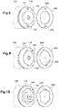
Figure 8 montre, isolément, le capot métallique frontal de la capsule et la bague support conjuguée solidaire de la vis d'ancrage, pour le mode de réalisation de laFigure 6 . - La
Figure 9 illustre une première variante des deux éléments de laFigure 8 . - La
Figure 10 illustre une seconde variante des deux éléments de laFigure 8 . - La
Figure 11 illustre un troisième mode de réalisation d'un ensemble frontal d'une capsule selon l'invention. - La
Figure 12 illustre deux éléments conjugués utilisés par l'ensemble frontal de laFigure 11 . - On va maintenant décrire plusieurs exemples de réalisation d'une capsule selon l'invention.
- Sur la
Figure 1 , on a représenté diverses possibilités de sites d'implantation d'un dispositif de type leadless, dans une application à la stimulation cardiaque. Ainsi, la capsule 10 est implantée à l'intérieur d'une cavité du myocarde (implant endocavitaire), par exemple à l'apex du ventricule droit. En variante, la capsule peut être également implantée sur le septum interventriculaire droit, comme en 10', ou encore sur une paroi auriculaire, comme en 10". Le dispositif peut également être une capsule épicardique placée sur une région externe du myocarde, comme en 10"'. Dans chaque cas, la capsule leadless est fixée à la paroi cardiaque au moyen d'un système d'ancrage saillant tel qu'une vis hélicoïdale pénétrant dans le tissu cardiaque pour le maintien sur le site d'implantation. D'autres systèmes d'ancrage sont utilisables, et ne modifient en aucune façon la mise en œuvre de la présente invention. - La
Figure 2 est une coupe longitudinale en vue perspective d'un exemple de capsule leadless montrant la configuration mécanique des différents éléments situés à l'intérieur de l'enveloppe tubulaire de la capsule. - La capsule leadless 10 se présente sous forme extérieure d'un implant avec un corps comprenant un corps tubulaire allongé cylindrique 100 enfermant les divers circuits électroniques et d'alimentation de la capsule ainsi que, dans l'exemple (non limitatif) illustré, un récupérateur d'énergie à ensemble pendulaire. Les dimensions typiques d'une telle capsule sont un diamètre de l'ordre de 6 mm pour une longueur d'environ 25 à 40 mm.
- Le corps tubulaire allongé 100 est fermé à son extrémité avant (proximale) 102 par un ensemble frontal 200 portant une vis hélicoïdale 202 pour l'ancrage de la capsule sur une paroi d'une cavité cardiaque, comme illustré plus haut à propos de la
Figure 1 (ce mode d'ancrage n'étant bien entendu aucunement limitatif). Une électrode de détection/ stimulation 104, en contact avec le tissu cardiaque au site d'implantation, assure le recueil des potentiels de dépolarisation cardiaque et/ou l'application d'impulsions de stimulation. - L'extrémité arrière (distale) opposée 106 du corps tubulaire 100 de la capsule 10 présente une forme arrondie atraumatique, et elle est pourvue de moyens appropriés 108 tels qu'une forme de préhension pour la liaison à un cathéter-guide ou autre accessoire d'implantation utilisable au moment de la mise en place ou de l'explantation de la capsule. Ces moyens permettent, par une action contrôlée par le praticien de rotation et de translation combinées du cathéter-guide, de guider la capsule vers le site d'implantation puis d'y assujettir celle-ci par vissage de l'élément d'ancrage dans la paroi.
- La capsule 10 est avantageusement pourvue d'un module de récupération d'énergie comprenant un ensemble pendulaire inertiel qui, à l'intérieur de la capsule, oscille au gré des diverses sollicitations externes auxquelles la capsule est soumise, et qui peuvent notamment résulter des mouvements de la paroi à laquelle est ancrée la capsule, qui sont transmis à l'implant par la vis d'ancrage 202, et/ou des variations du débit du flux sanguin dans le milieu environnant l'implant, qui produisent des oscillations de l'implant au rythme des battements cardiaques, et/ou des vibrations diverses transmises par les tissus cardiaques.
- L'ensemble pendulaire peut notamment être constitué d'une lame piézoélectrique 110 encastrée en 112 à l'une de ses extrémités et dont l'extrémité opposée, libre, est couplée à une masse inertielle mobile 114. La lame piézoélectrique 110 est une lame flexible élastiquement déformable qui constitue, avec la masse inertielle 114, un système pendulaire de type masse-ressort qui, du fait de l'inertie de la masse inertielle 114, soumet la lame 110 à une déformation de type vibratoire de part et d'autre d'une position neutre ou non déformée, correspondant à sa position stable de repos en l'absence de toute sollicitation. La lame piézoélectrique 110 assure en outre une fonction de transducteur mécanoélectrique permettant de convertir en charges électriques la sollicitation mécanique qui lui est appliquée lorsqu'elle est fléchie, charges récupérées par des électrodes (non représentées) formées à la surface de la lame pour produire un signal électrique qui, après redressement, stabilisation et filtrage alimentera les divers circuits électroniques de la capsule.
- La
Figure 3 illustre, isolément, l'ensemble frontal 200 de la capsule monté à l'extrémité proximale du corps tubulaire 100 de la capsule, avec l'électrode 104 destinée à venir en appui contre la surface du tissu à l'endroit du site d'implantation et la vis hélicoïdale 202 destinée à pénétrer dans ce tissu pour permettre l'ancrage de la capsule au site d'implantation. - La vis 202 est solidaire en rotation d'une bague support 204, la vis étant par exemple soudée à cette bague support, les deux éléments étant métalliques, par exemple en acier inoxydable tel qu'un acier 316 L ou encore un métal tel que le titane, le tantale ou un alliage nickel-titane de type nitinol.
- (On notera incidemment que tous les éléments solidaires du corps tubulaire 100 seront désignés par une référence numérique de type 1nn, tandis que tous ceux qui sont solidaires de l'ensemble frontal 200 seront désignés par une référence numérique de type 2nn).
- Le corps tubulaire 100 est terminé en vis-à-vis de la bague support 204 par un capot de fermeture 116 de forme sensiblement plate et contre lequel la bague support 204 vient en appui. Le capot de fermeture 116, tout comme le corps tubulaire 100 de la capsule, sont des éléments métalliques, par exemple en titane ou en acier inoxydable tel qu'un acier 316 L, ou encore en un alliage nickel-titane de type nitinol, les deux pièces 100 et 116 étant par exemple soudées ensemble.
- De façon caractéristique de l'invention, l'ensemble frontal 200, comprenant donc la vis d'ancrage 202 avec sa bague support 204, dispose par rapport au corps tubulaire 100 et à son capot de fermeture 116 d'un degré de liberté en rotation axiale (c'est-à-dire autour de l'axe central D).
- Dans certaines configurations particulières, telles que celles des modes de réalisation des
Figures 6 et 7 que l'on décrira plus loin, l'ensemble frontal 200 et le corps tubulaire 100 peuvent également présenter un degré de liberté en translation axiale (c'est-à-dire parallèlement à l'axe D). En revanche, dans d'autres modes de réalisation, tels que ceux illustrésFigures 4 et11 , l'ensemble frontal 200 ne dispose que d'un seul degré de liberté en rotation axiale par rapport au corps tubulaire 100 et aux éléments solidaires de ce dernier. - De façon également caractéristique de l'invention, le corps tubulaire 100 ainsi que les éléments dont il est solidaire, d'une part, et l'ensemble frontal 200, d'autre part, sont couplés entre eux par des moyens débrayables, grâce à divers mécanismes dont on décrira plusieurs réalisations en référence aux
Figures 4 à 12 . Ces moyens débrayables sont en particulier agencés pour assurer une fonction de limiteur de couple entre le corps tubulaire (qui reçoit une sollicitation externe au moment de l'implantation via l'outil de pose manipulé par le praticien) et la vis d'ancrage (qui pénètre dans le tissu, et pour lequel il est indispensable d'éviter tout effet de carottage). - Le mécanisme limiteur de couple permet, lorsque le corps tubulaire est sollicité en rotation et applique donc à la vis d'ancrage un couple correspondant qui permet la pénétration de celle-ci dans le tissu, d'assurer la transmission de ce couple d'entrainement tant qu'il est inférieur à un couple seuil prédéterminé (choisi pour être inférieur au couple de carottage) et, si le couple d'entrainement dépasse ce seuil, empêche le carottage, soit en limitant ce couple (qui continuera à être transmis du corps tubulaire à l'ensemble frontal), soit en débrayant totalement l'ensemble frontal du corps tubulaire (mettant ainsi fin à la transmission du couple d'entrainement). Le couple seuil prédéterminé déclenchant le découplage de l'ensemble frontal d'avec le corps tubulaire est typiquement inférieur à 1N.cm, pour éviter tout risque de carottage par la vis hélicoïdale au moment de l'implantation. Concrètement, le couple de réaction augmente de façon relativement brusque lorsque la face avant de la capsule (en l'occurrence, l'électrode 104) touche la surface du tissu cardiaque, exerçant alors sur la vis d'ancrage une force de réaction axiale qui, en l'absence d'action de débrayage ou de limitation du couple, serait susceptible de produire un carottage.
- On verra également que les divers mécanismes de couplage débrayable décrits permettent, une fois le débrayage opéré, de conserver un degré de liberté en rotation du corps tubulaire par rapport à l'ensemble frontal, de manière à pouvoir modifier éventuellement l'orientation du corps tubulaire in situ sans pour autant modifier la position de la vis hélicoïdale, donc en maintenant l'ancrage tel qu'il avait été initialement assuré.
- Cette modification ultérieure de l'orientation angulaire résultera d'une action de rotation exercée sur le corps tubulaire, étant entendu que, en l'absence d'une telle sollicitation, l'orientation de la capsule ne sera pas modifiée et restera celle qui avait été initialement obtenue.
- En référence aux
Figures 4 et 5 , on va décrire un premier mode de réalisation de l'invention, dans lequel l'ensemble frontal 200 et le corps tubulaire 100 sont mobiles entre eux suivant un unique degré de liberté, en rotation autour de l'axe D. - Le corps tubulaire 100 et son capot de fermeture 116 forment un ensemble solidaire avec l'électrode 104 portée par une bague support d'électrode 118 en matériau électriquement isolant, par exemple un polymère thermoplastique de polyuréthane de type Tecothane® ou un polymère de type PET (poly(téréphtalate d'éthylène)) ou PEEK (polyétheréthercétone), ou autre matière plastique injectable. L'électrode 104 est reliée aux circuits électroniques situés à l'intérieur du corps tubulaire 100 par un fil de liaison 120 traversant le capot 116 et isolé de celui-ci par une traversée 122 (illustrée plus en détail sur les
Figures 7 et11 ). - Le capot 116 comporte une excroissance tubulaire 128 recevant et supportant un capuchon 124 en forme de bague, avec avantageusement dans la région proche de l'électrode 104 une bague additionnelle 126 incorporant un matériau susceptible de diffuser un agent stéroïde.
- En ce qui concerne l'ensemble frontal 200, qui est mobile en rotation par rapport aux divers éléments 100 à 128 que l'on vient de décrire, cet ensemble comprend la bague support 204, qui est solidaire de la vis d'ancrage 202 et comprend une surface d'appui 206 tournée vers une surface homologue annulaire 130 du capot 116. Ces deux surfaces 130 et 206, toutes deux métalliques, forment une première interface 304 avec un effet de friction mutuelle.
- La surface opposée 208 de la bague support 204 vient en appui contre un ressort annulaire 300, le ressort 300 et la bague 204 n'étant pas solidaires entre eux. Entre les deux éléments constitués par la surface 208 de la bague 204 et le ressort 300 se forme une deuxième interface 304 avec effet de friction mutuelle. Côté proximal, le ressort 300 vient en appui contre une surface 132 du capuchon 124.
- Le ressort annulaire 300, qui se trouve donc ainsi axialement emprisonné entre la bague support 204 et le capuchon 124, exerce sur la bague support 204 un effort axial en direction du corps tubulaire 100, effort se traduisant par un effet de frottement aux interfaces 302 et 304.
- Ce mécanisme de couplage frottant entre, d'une part, le corps tubulaire 100 et les différents éléments qui lui sont solidaires et, d'autre part, l'ensemble frontal 200 avec notamment la vis d'ancrage 202, permet de limiter le couple transmis par le corps tubulaire à la vis d'ancrage 202 et de réaliser ainsi l'effet limiteur de couple anti-carottage recherché.
- On notera également qu'il reste toujours possible de réorienter axialement le corps tubulaire une fois la capsule ancrée dans la paroi, et ce sans exercer d'action de rotation sur la vis, donc sans risque de survissage pouvant entrainer un carottage.
- Cette faculté peut se révéler intéressante dans le cas d'une capsule munie d'un récupérateur d'énergie tel que celui illustré
Figure 2 , comprenant une masse inertielle montée à l'extrémité d'une lame flexible : avec cette configuration, la récupération de l'énergie peut varier en fonction de l'orientation dans l'espace de la direction de flexion de la lame par rapport à la paroi cardiaque, de sorte qu'il peut être avantageux de tenter d'optimiser la conversion d'énergie en faisant tourner le corps de la capsule jusqu'à trouver la position qui maximise cette conversion. - Si, par ailleurs, on souhaite explanter la capsule, un couple de rotation exercé en sens inverse sur le corps tubulaire permettra de transmettre le mouvement de dévissage à la vis hélicoïdale et donc de détacher progressivement la capsule de la paroi.
- Pour le ressort 300, le choix d'un ressort ondulé présente l'avantage d'une très grande compacité, compatible avec les exigences de miniaturisation extrême des capsules leadless. La longueur du ressort, c'est-à-dire l'intervalle compris entre les surfaces en vis-à-vis 208 et 132, est typiquement de l'ordre de a = 1,6 mm, ce qui permet de réaliser un ensemble de longueur réduite, par exemple de longueur b = 3 mm (la partie saillante de la vis, correspondant à la longueur pénétrant dans la paroi, étant typiquement de c = 1,6 mm environ).
- L'avantage du ressort ondulé est le gain de place axial qu'il permet, typiquement de 50 % par rapport à un ressort filaire hélicoïdal conventionnel. D'autres types de ressorts ou éléments fonctionnement analogues sont toutefois envisageables, tels que : entretoise en matériau souple, par exemple en silicone, ressort hélicoïdal de compression, lame ressort, bague plastique déformable, etc., l'important étant que cet élément puisse engendrer un frottement suffisant pour limiter le couple à la valeur choisie, tout en maintenant l'orientation angulaire du corps tubulaire 100 par rapport à l'ensemble frontal en l'absence de couple appliqué de l'extérieur au corps tubulaire.
- La
Figure 6 illustre un deuxième mode de réalisation de l'invention, où le corps tubulaire 100 et l'ensemble frontal 200 sont mobiles non seulement en rotation autour de l'axe D, mais également en translation axiale : plus précisément, l'ensemble formé par le corps tubulaire 100 avec les éléments qu'il porte, notamment l'électrode 104, peut reculer en direction distale (c'est-à-dire vers la gauche avec les conventions de la figure) par rapport à l'ensemble frontal 200. Avant ce mouvement de translation axiale, les deux ensembles 100 et 200 sont solidaires en rotation, mais une fois la translation axiale effectuée, ils deviennent libres en rotation relative. - La translation axiale a lieu quand, au moment du vissage, la face frontale de l'électrode 104 vient en contact avec la surface du tissu dans lequel la vis 202 est en train de pénétrer. L'électrode 104 et donc le corps tubulaire 100 ne peuvent plus progresser, alors que, du fait de la rotation, la vis d'ancrage 200 continue à pénétrer dans le tissu. Il en résulte un recul progressif (flèche 134) en direction axiale du corps tubulaire 100 et de l'électrode 104 par rapport à l'ensemble frontal 200 et à la vis 20, ceci jusqu'à produire un débrayage de ces deux ensembles l'un par rapport à l'autre.
- Pour ce faire, comme illustré
Figure 8 , la face 130 du capot 116 tournée vers la bague support est munie de pions 134 destinés à s'emboiter dans des alésages homologues 208 de la bague support 204. Par ailleurs, un élément élastique 306 (Figure 6 ), par exemple une bague silicone, est interposé entre le capuchon 124 et la bague support 204, de manière à exercer une force axiale d'un niveau prédéterminé entre la face 130 du capot 116 et la bague support 204. - De la sorte, la pénétration progressive de la vis 202 dans le tissu, qui a pour effet de repousser axialement l'électrode 104 et donc le corps tubulaire 100 et son capot de fermeture 116 (flèche 134) va avoir pour effet de progressivement sortir les pions 134 des alésages 208. Lorsque les pions seront totalement sortis des alésages, alors la bague support 204 sera découplée en rotation du capot 116, réalisant la fonction de limitation de couple recherchée.
- Les
Figures 9 et 10 illustrent des variantes de laFigure 8 , dans laquelle les pions 134 et les alésages 208 sont remplacés par des excroissances 134' coopérant avec des encoches homologues 208' de la bague support 204 ou (Figure 10 ) par un profil non circulaire 140 (hexagonal dans l'exemple illustré) coopérant avec un profil conjugué 210 de la bague support 204. - La
Figure 7 illustre une variante du mode de réalisation de laFigure 6 . - Cette variante met en œuvre comme élément élastique des rondelles ondulées 308 interposées entre la bague support 204 et un épaulement 142 d'un élément annulaire 144 solidaire du capot 116.
- La pénétration progressive de la vis 202 a pour effet de repousser l'électrode 104 et le corps tubulaire 100 en direction distale (vers la gauche avec les conventions de la figure), tandis que la vis 202 continuera de progresser dans le tissu, en direction proximale (vers la droite). Ce mouvement de translation relative a pour conséquence de comprimer les rondelles ondulées 308, jusqu'à produire un débrayage entre le capot de fermeture 116 et la bague support 204.
- La
Figure 11 illustre un troisième mode de réalisation de l'invention, dans lequel le corps tubulaire 100 et l'électrode 104, d'une part, et l'ensemble frontal 200 avec la vis d'ancrage 202, d'autre part, ne sont pas mobiles axialement, à la différence du mode de réalisation précédent. - Dans ce troisième mode de réalisation, l'élément élastique est constitué par la bague support 204 elle-même qui, comme on peut le voir sur la
Figure 12 où elle a été illustrée isolément, est une bague annulaire fendue, avec une fente radiale 212. Cette fente radiale procure à la bague support 204 une élasticité radiale, à la manière d'un anneau élastique de type circlip. - La bague support 204 est par ailleurs munie à sa périphérie intérieure 214 de bossages 216 coopérant avec des creux homologues 142 prévus sur une surface extérieure 144 formant rampe d'un épaulement 146 du capot de fermeture 116.
- Tant que le couple exercé sur le corps tubulaire 100, et donc le couple transmis au capot 116 et à la bague support 204 via les éléments conjugués 142, 216, est inférieur à un couple prédéterminé, la bague support 204 ne se déforme pas, ce qui permet la transmission de ce couple de rotation à la bague support 204 et donc à la vis 202. En revanche, lorsque le couple augmente au-delà de la valeur prescrite, la bague support fendue 204 se déforme radialement, de sorte que les bossages 216 quittent les évidements 142, réalisant ainsi la fonction recherchée de limitation de couple et de débrayage.
Claims (13)
- Une capsule autonome implantable, comprenant :- un corps tubulaire (100) logeant un ensemble d'éléments fonctionnels de la capsule, et- à une extrémité proximale (102) de la capsule, un ensemble frontal (200) comprenant un organe d'ancrage (202) pour l'ancrage de la capsule à une paroi d'un organe du patient,caractérisée en ce que l'ensemble frontal (200) est, avec l'organe d'ancrage (200), mobile en rotation relative axiale par rapport au corps tubulaire (100),
et en ce que la capsule comprend en outre, entre l'ensemble frontal et le corps tubulaire :- un organe de couplage débrayable agencé pour :• autoriser ladite rotation relative lorsque le corps tubulaire reçoit une sollicitation externe en rotation qui lui est appliquée avec l'organe d'ancrage ancré dans la paroi de l'organe du patient, l'organe d'ancrage exerçant alors un couple de réaction supérieur à un couple seuil prédéterminé, et• empêcher ladite rotation relative en l'absence de sollicitation externe en rotation appliquée au corps tubulaire. - La capsule de la revendication 1, dans laquelle l'organe de couplage débrayable comprend :- au moins une interface de friction (302, 304) entre l'ensemble frontal et le corps tubulaire ; et- un élément élastiquement déformable (300) agencé pour appliquer un effort de compression axiale entre une première face d'appui (132) solidaire en rotation du corps tubulaire (100) et une seconde face d'appui (208) solidaire en rotation de l'ensemble frontal (200).
- La capsule de la revendication 2, dans laquelle, en l'absence de sollicitation externe en rotation appliquée au corps tubulaire, l'élément élastiquement déformable applique à l'endroit de l'interface de friction un effort supérieur au couple seuil prédéterminé.
- La capsule de la revendication 2, dans laquelle l'organe de couplage débrayable comprend une bague support (204) solidaire en rotation de l'organe d'ancrage (202) et venant en appui frottant contre une surface annulaire frontale (130) du corps tubulaire (100) située à l'extrémité proximale de celui-ci.
- La capsule de la revendication 4, dans laquelle l'élément élastiquement déformable (300) applique l'effort de compression axiale contre la bague support en direction de la surface annulaire frontale (130).
- La capsule de la revendication 4, dans laquelle la bague support comprend deux faces (206, 208), comprenant :- une première face (206) tournée vers la surface annulaire frontale (130), avec un degré de liberté en rotation et un premier contact frottant à l'interface (304) entre la première face et la surface annulaire frontale ; et- une seconde face (208) opposée tournée vers l'élément élastiquement déformable (300), avec un degré de liberté en rotation et un second contact frottant à l'interface (302) entre la seconde face et l'élément élastiquement déformable.
- La capsule de la revendication 2, dans laquelle le corps tubulaire (100) et l'ensemble frontal (200) ne sont pas mobiles entre eux en translation axiale.
- La capsule de la revendication 1, dans laquelle l'organe de couplage débrayable comprend :- une bague support (204) solidaire en rotation de l'organe d'ancrage (202) ;- une surface frontale (116) du corps tubulaire (100), située à l'extrémité proximale de celui-ci en vis-à-vis de la bague support ; et- des formes conjuguées (134, 208 ; 134', 208' ; 140, 210 ; 144, 214) prévues respectivement sur la bague support (204) et sur la surface frontale (116), les formes conjuguées permettant un emboitement mutuel du corps tubulaire (100) avec l'ensemble frontal (200) pour permettre un entrainement en rotation de la bague support (204), et corrélativement de l'organe d'ancrage (202) solidaire de celle-ci, par l'organe d'emboitement de la surface frontale sous l'effet de la sollicitation externe en rotation appliquée au corps tubulaire.
- La capsule de la revendication 8, dans laquelle le corps tubulaire (100) et l'ensemble frontal (200) sont mobiles entre eux en translation axiale, et le corps tubulaire porte à son extrémité proximale un élément (104) destiné à venir en appui contre la paroi de l'organe du patient, cet élément (104) étant apte à exercer durant la pénétration de l'organe d'ancrage (202) un effort de réaction axial (136) propre à déboiter axialement les formes conjuguées respectives (134, 208 ; 134', 208'; 140, 210) de la bague support (204) et de la surface frontale (116).
- La capsule de la revendication 9, dans laquelle l'organe de couplage débrayable comprend en outre un élément élastiquement déformable (306, 308) agencé pour solliciter axialement les formes conjuguées en rapprochement mutuel.
- La capsule de la revendication 10, dans laquelle l'élément élastiquement déformable (306, 308) est agencé pour subir, sous l'effet dudit effort de réaction axial (136), une déformation d'un état non déformé à un état de déformation maximale correspondant audit couple seuil prédéterminé.
- La capsule de la revendication 2 ou de la revendication 10, dans laquelle l'élément élastiquement déformable est un élément du groupe constitué par : bague ondulée (308), ressort de compression, lame ressort, bague plastique déformable (306) et entretoise en matériau souple.
- La capsule de la revendication 8, dans laquelle le corps tubulaire (100) et l'ensemble frontal (200) ne sont pas mobiles entre eux en translation axiale, et dans laquelle l'organe de couplage débrayable comprend un élément élastiquement déformable (204, 212) agencé pour subir, sous l'effet dudit couple de réaction, une déformation entre :- un état où l'élément élastiquement déformable exerce entre les formes conjuguées (144, 214) un effort de striction radiale assurant l'emboitement mutuel du corps tubulaire (100) avec l'ensemble frontal (200), et- un état de déformation maximale propre à déboiter le corps tubulaire (100) et l'ensemble frontal (200), pour un couple de réaction correspondant audit couple seuil prédéterminé.
Applications Claiming Priority (2)
| Application Number | Priority Date | Filing Date | Title |
|---|---|---|---|
| FR1871085A FR3086179B1 (fr) | 2018-09-25 | 2018-09-25 | Capsule cardiaque autonome implantable a tete orientable et limiteur de couple |
| PCT/EP2019/069893 WO2020064172A1 (fr) | 2018-09-25 | 2019-07-24 | Capsule cardiaque autonome implantable à tête orientable et limiteur de couple |
Publications (2)
| Publication Number | Publication Date |
|---|---|
| EP3681589A1 EP3681589A1 (fr) | 2020-07-22 |
| EP3681589B1 true EP3681589B1 (fr) | 2020-11-25 |
Family
ID=65244362
Family Applications (1)
| Application Number | Title | Priority Date | Filing Date |
|---|---|---|---|
| EP19744687.5A Active EP3681589B1 (fr) | 2018-09-25 | 2019-07-24 | Capsule cardiaque autonome implantable à tête orientable et limiteur de couple |
Country Status (4)
| Country | Link |
|---|---|
| US (1) | US11197997B2 (fr) |
| EP (1) | EP3681589B1 (fr) |
| FR (1) | FR3086179B1 (fr) |
| WO (1) | WO2020064172A1 (fr) |
Families Citing this family (8)
| Publication number | Priority date | Publication date | Assignee | Title |
|---|---|---|---|---|
| US11229800B2 (en) * | 2019-03-12 | 2022-01-25 | Cairdac | Piezoelectric energy harvester including a monitoring circuit for detecting harvester alteration or downgrading |
| EP4017350B1 (fr) | 2019-08-22 | 2025-04-09 | Edwards Lifesciences Corporation | Capteur cardiaque ancré aux vaisseaux sanguins |
| US11918820B2 (en) | 2020-01-21 | 2024-03-05 | Pacesetter, Inc. | Leadless biostimulator having overmolded header assembly |
| EP3892325B1 (fr) * | 2020-04-09 | 2022-03-16 | Cairdac | Implant cardiaque autonome de type capsule leadless, comprenant un récupérateur d'énergie à lame piézoélectrique |
| EP4059565B1 (fr) * | 2021-03-15 | 2022-11-23 | Cairdac | Capsule cardiaque autonome implantable et extractible à tête orientable et limiteur de couple |
| CA3218240A1 (fr) * | 2021-05-14 | 2022-11-17 | Edwards Lifesciences Corporation | Dispositifs d'implant de capteur a double ancrage |
| EP4205799B1 (fr) * | 2021-12-29 | 2024-02-14 | Cairdac | Dispositif médical implantable à vis d'ancrage hélicoïdale non traumatique |
| EP4289469A1 (fr) * | 2022-06-08 | 2023-12-13 | BIOTRONIK SE & Co. KG | Ensemble calotte pour un dispositif intracardiaque implantable et ledit dispositif intracardiaque |
Family Cites Families (13)
| Publication number | Priority date | Publication date | Assignee | Title |
|---|---|---|---|---|
| US9155479B2 (en) | 2005-12-12 | 2015-10-13 | Tor Peters | Intra cardiac device, system and methods |
| ATE531420T1 (de) * | 2009-04-28 | 2011-11-15 | Sorin Crm Sas | Intrakardialer sensor zur stimulation oder defibrillation mit zurückziehbarer schraube |
| US9775982B2 (en) * | 2010-12-29 | 2017-10-03 | Medtronic, Inc. | Implantable medical device fixation |
| EP2537555B1 (fr) * | 2011-06-24 | 2013-05-01 | Sorin CRM SAS | Implant intracardiaque autonome de type leadless à élément de fixation désolidarisable |
| EP2818202B1 (fr) * | 2013-06-24 | 2016-04-13 | Sorin CRM SAS | Système d'accouplement entre un dispositif médical et son accessoire d'implantation in situ |
| EP2818201B1 (fr) * | 2013-06-24 | 2016-07-20 | Sorin CRM SAS | Capsule intracardiaque et accessoire d'implantation in situ par voie fémorale |
| EP2881141B1 (fr) * | 2013-12-04 | 2016-06-01 | Sorin CRM SAS | Capsule intracardiaque implantable sur une paroi mince, notamment la paroi septale |
| FR3022790A1 (fr) * | 2014-06-25 | 2016-01-01 | Sorin Crm Sas | Capsule implantable a fixation par vissage, notamment capsule autonome de stimulation cardiaque |
| US9610454B2 (en) * | 2015-04-13 | 2017-04-04 | Pacesetter, Inc. | Over torque limiter for leadless implantable medical devices |
| US9907953B2 (en) * | 2015-10-15 | 2018-03-06 | Pacesetter, Inc. | Fixation sleeve equipped leadless pulse generator |
| EP3173126B1 (fr) | 2015-11-27 | 2020-03-25 | Sorin CRM SAS | Capsule implantable, notamment capsule autonome de stimulation cardiaque, et son procede d'assemblage |
| EP3248649B1 (fr) | 2016-05-24 | 2019-01-02 | Sorin CRM SAS | Mécanisme limiteur de couple entre un dispositif médical et son accessoire d'implantation |
| US11389657B2 (en) | 2016-12-30 | 2022-07-19 | Sorin Crm Sas | Autonomous implantable capsule for heart stimulation |
-
2018
- 2018-09-25 FR FR1871085A patent/FR3086179B1/fr not_active Expired - Fee Related
-
2019
- 2019-07-24 WO PCT/EP2019/069893 patent/WO2020064172A1/fr not_active Ceased
- 2019-07-24 EP EP19744687.5A patent/EP3681589B1/fr active Active
- 2019-08-07 US US16/533,782 patent/US11197997B2/en not_active Expired - Fee Related
Non-Patent Citations (1)
| Title |
|---|
| None * |
Also Published As
| Publication number | Publication date |
|---|---|
| WO2020064172A1 (fr) | 2020-04-02 |
| EP3681589A1 (fr) | 2020-07-22 |
| FR3086179B1 (fr) | 2020-09-25 |
| US11197997B2 (en) | 2021-12-14 |
| FR3086179A1 (fr) | 2020-03-27 |
| US20200094048A1 (en) | 2020-03-26 |
Similar Documents
| Publication | Publication Date | Title |
|---|---|---|
| EP3681589A1 (fr) | Capsule cardiaque autonome implantable à tête orientable et limiteur de couple | |
| EP2818201B1 (fr) | Capsule intracardiaque et accessoire d'implantation in situ par voie fémorale | |
| FR3082434A1 (fr) | Implant cardiaque autonome de type "capsule leadless", comprenant un recuperateur d'energie a lame piezoelectrique | |
| EP2818202B1 (fr) | Système d'accouplement entre un dispositif médical et son accessoire d'implantation in situ | |
| EP3173126A1 (fr) | Capsule implantable, notamment capsule autonome de stimulation cardiaque | |
| EP3892325B1 (fr) | Implant cardiaque autonome de type capsule leadless, comprenant un récupérateur d'énergie à lame piézoélectrique | |
| EP2881141B1 (fr) | Capsule intracardiaque implantable sur une paroi mince, notamment la paroi septale | |
| EP0779080B1 (fr) | Sondes à barbes d'ancrage pliables pour dispositif médical implanté, notamment pour stimulateur cardiaque | |
| EP2959940B1 (fr) | Capsule implantable à fixation par vissage, notamment capsule autonome de stimulation cardiaque | |
| EP0568463B1 (fr) | Sonde pour stimulateur cardiaque | |
| EP2959936B1 (fr) | Capsule inplantable à fixation par vissage, notamment capsule autonome de stimulation cardiaque | |
| EP2537555B1 (fr) | Implant intracardiaque autonome de type leadless à élément de fixation désolidarisable | |
| EP2394695A1 (fr) | Capsule intracardiaque autonome et son accessoire d'implantation | |
| EP2384788B1 (fr) | Système sans vis de connexion rapide d'un connecteur de sonde à un générateur de dispositif médical implantable | |
| FR2835189A1 (fr) | Necessaire de mise en place d'une sonde intracardiaque de stimulation ou de defibrillation du type a vis retractable | |
| EP4059565B1 (fr) | Capsule cardiaque autonome implantable et extractible à tête orientable et limiteur de couple | |
| EP4205799B1 (fr) | Dispositif médical implantable à vis d'ancrage hélicoïdale non traumatique | |
| EP2545958A1 (fr) | Sonde pour prothèse cardiaque implantable, comprenant des moyens de protection contre les effets thermiques des champs IRM | |
| EP3639884B1 (fr) | Système d'accouplement entre une capsule cardiaque autonome et son outil d'implantation | |
| EP4015034A1 (fr) | Implant cardiaque autonome de type capsule leadless, comprenant une interface de recharge de batterie et de communication externe pendant le transport et le stockage | |
| EP4276923B1 (fr) | Récupérateur d'énergie piézoélectrique avec lame à débattement contrôlé, notamment pour l'alimentation d'une capsule cardiaque autonome leadless | |
| EP4336990B1 (fr) | Ensemble pendulaire à masse inertielle monolithique monté sur une lame piézoélectrique, notamment pour un récupérateur d'énergie de capsule cardiaque autonome leadless | |
| EP0784993A1 (fr) | Sonde pour dispositif médical implanté, notamment pour stimulateur cardiaque | |
| EP4346082B1 (fr) | Ensemble pendulaire à masse inertielle montée sur une lame piézoélectrique, notamment pour un récupérateur d'énergie de capsule cardiaque autonome leadless et un procédé d'assemblage correspondant | |
| FR2932688A1 (fr) | Mandrin bi-matiere de guidage d'une sonde en contact avec la paroi du septum |
Legal Events
| Date | Code | Title | Description |
|---|---|---|---|
| STAA | Information on the status of an ep patent application or granted ep patent |
Free format text: STATUS: UNKNOWN |
|
| STAA | Information on the status of an ep patent application or granted ep patent |
Free format text: STATUS: THE INTERNATIONAL PUBLICATION HAS BEEN MADE |
|
| PUAI | Public reference made under article 153(3) epc to a published international application that has entered the european phase |
Free format text: ORIGINAL CODE: 0009012 |
|
| STAA | Information on the status of an ep patent application or granted ep patent |
Free format text: STATUS: REQUEST FOR EXAMINATION WAS MADE |
|
| 17P | Request for examination filed |
Effective date: 20200415 |
|
| AK | Designated contracting states |
Kind code of ref document: A1 Designated state(s): AL AT BE BG CH CY CZ DE DK EE ES FI FR GB GR HR HU IE IS IT LI LT LU LV MC MK MT NL NO PL PT RO RS SE SI SK SM TR |
|
| AX | Request for extension of the european patent |
Extension state: BA ME |
|
| GRAJ | Information related to disapproval of communication of intention to grant by the applicant or resumption of examination proceedings by the epo deleted |
Free format text: ORIGINAL CODE: EPIDOSDIGR1 |
|
| STAA | Information on the status of an ep patent application or granted ep patent |
Free format text: STATUS: GRANT OF PATENT IS INTENDED |
|
| GRAP | Despatch of communication of intention to grant a patent |
Free format text: ORIGINAL CODE: EPIDOSNIGR1 |
|
| GRAS | Grant fee paid |
Free format text: ORIGINAL CODE: EPIDOSNIGR3 |
|
| GRAA | (expected) grant |
Free format text: ORIGINAL CODE: 0009210 |
|
| STAA | Information on the status of an ep patent application or granted ep patent |
Free format text: STATUS: THE PATENT HAS BEEN GRANTED |
|
| DAV | Request for validation of the european patent (deleted) | ||
| DAX | Request for extension of the european patent (deleted) | ||
| INTG | Intention to grant announced |
Effective date: 20201006 |
|
| AK | Designated contracting states |
Kind code of ref document: B1 Designated state(s): AL AT BE BG CH CY CZ DE DK EE ES FI FR GB GR HR HU IE IS IT LI LT LU LV MC MK MT NL NO PL PT RO RS SE SI SK SM TR |
|
| REG | Reference to a national code |
Ref country code: GB Ref legal event code: FG4D Free format text: NOT ENGLISH |
|
| REG | Reference to a national code |
Ref country code: CH Ref legal event code: EP |
|
| REG | Reference to a national code |
Ref country code: DE Ref legal event code: R096 Ref document number: 602019001488 Country of ref document: DE |
|
| REG | Reference to a national code |
Ref country code: CH Ref legal event code: NV Representative=s name: VALIPAT S.A. C/O BOVARD SA NEUCHATEL, CH Ref country code: AT Ref legal event code: REF Ref document number: 1337595 Country of ref document: AT Kind code of ref document: T Effective date: 20201215 |
|
| REG | Reference to a national code |
Ref country code: IE Ref legal event code: FG4D Free format text: LANGUAGE OF EP DOCUMENT: FRENCH |
|
| REG | Reference to a national code |
Ref country code: AT Ref legal event code: MK05 Ref document number: 1337595 Country of ref document: AT Kind code of ref document: T Effective date: 20201125 |
|
| REG | Reference to a national code |
Ref country code: NL Ref legal event code: MP Effective date: 20201125 |
|
| PG25 | Lapsed in a contracting state [announced via postgrant information from national office to epo] |
Ref country code: NO Free format text: LAPSE BECAUSE OF FAILURE TO SUBMIT A TRANSLATION OF THE DESCRIPTION OR TO PAY THE FEE WITHIN THE PRESCRIBED TIME-LIMIT Effective date: 20210225 Ref country code: GR Free format text: LAPSE BECAUSE OF FAILURE TO SUBMIT A TRANSLATION OF THE DESCRIPTION OR TO PAY THE FEE WITHIN THE PRESCRIBED TIME-LIMIT Effective date: 20210226 Ref country code: FI Free format text: LAPSE BECAUSE OF FAILURE TO SUBMIT A TRANSLATION OF THE DESCRIPTION OR TO PAY THE FEE WITHIN THE PRESCRIBED TIME-LIMIT Effective date: 20201125 Ref country code: RS Free format text: LAPSE BECAUSE OF FAILURE TO SUBMIT A TRANSLATION OF THE DESCRIPTION OR TO PAY THE FEE WITHIN THE PRESCRIBED TIME-LIMIT Effective date: 20201125 Ref country code: PT Free format text: LAPSE BECAUSE OF FAILURE TO SUBMIT A TRANSLATION OF THE DESCRIPTION OR TO PAY THE FEE WITHIN THE PRESCRIBED TIME-LIMIT Effective date: 20210325 |
|
| PG25 | Lapsed in a contracting state [announced via postgrant information from national office to epo] |
Ref country code: PL Free format text: LAPSE BECAUSE OF FAILURE TO SUBMIT A TRANSLATION OF THE DESCRIPTION OR TO PAY THE FEE WITHIN THE PRESCRIBED TIME-LIMIT Effective date: 20201125 Ref country code: LV Free format text: LAPSE BECAUSE OF FAILURE TO SUBMIT A TRANSLATION OF THE DESCRIPTION OR TO PAY THE FEE WITHIN THE PRESCRIBED TIME-LIMIT Effective date: 20201125 Ref country code: IS Free format text: LAPSE BECAUSE OF FAILURE TO SUBMIT A TRANSLATION OF THE DESCRIPTION OR TO PAY THE FEE WITHIN THE PRESCRIBED TIME-LIMIT Effective date: 20210325 Ref country code: SE Free format text: LAPSE BECAUSE OF FAILURE TO SUBMIT A TRANSLATION OF THE DESCRIPTION OR TO PAY THE FEE WITHIN THE PRESCRIBED TIME-LIMIT Effective date: 20201125 Ref country code: BG Free format text: LAPSE BECAUSE OF FAILURE TO SUBMIT A TRANSLATION OF THE DESCRIPTION OR TO PAY THE FEE WITHIN THE PRESCRIBED TIME-LIMIT Effective date: 20210225 Ref country code: AT Free format text: LAPSE BECAUSE OF FAILURE TO SUBMIT A TRANSLATION OF THE DESCRIPTION OR TO PAY THE FEE WITHIN THE PRESCRIBED TIME-LIMIT Effective date: 20201125 |
|
| REG | Reference to a national code |
Ref country code: LT Ref legal event code: MG9D |
|
| PG25 | Lapsed in a contracting state [announced via postgrant information from national office to epo] |
Ref country code: HR Free format text: LAPSE BECAUSE OF FAILURE TO SUBMIT A TRANSLATION OF THE DESCRIPTION OR TO PAY THE FEE WITHIN THE PRESCRIBED TIME-LIMIT Effective date: 20201125 |
|
| PG25 | Lapsed in a contracting state [announced via postgrant information from national office to epo] |
Ref country code: SM Free format text: LAPSE BECAUSE OF FAILURE TO SUBMIT A TRANSLATION OF THE DESCRIPTION OR TO PAY THE FEE WITHIN THE PRESCRIBED TIME-LIMIT Effective date: 20201125 Ref country code: SK Free format text: LAPSE BECAUSE OF FAILURE TO SUBMIT A TRANSLATION OF THE DESCRIPTION OR TO PAY THE FEE WITHIN THE PRESCRIBED TIME-LIMIT Effective date: 20201125 Ref country code: EE Free format text: LAPSE BECAUSE OF FAILURE TO SUBMIT A TRANSLATION OF THE DESCRIPTION OR TO PAY THE FEE WITHIN THE PRESCRIBED TIME-LIMIT Effective date: 20201125 Ref country code: CZ Free format text: LAPSE BECAUSE OF FAILURE TO SUBMIT A TRANSLATION OF THE DESCRIPTION OR TO PAY THE FEE WITHIN THE PRESCRIBED TIME-LIMIT Effective date: 20201125 Ref country code: RO Free format text: LAPSE BECAUSE OF FAILURE TO SUBMIT A TRANSLATION OF THE DESCRIPTION OR TO PAY THE FEE WITHIN THE PRESCRIBED TIME-LIMIT Effective date: 20201125 Ref country code: LT Free format text: LAPSE BECAUSE OF FAILURE TO SUBMIT A TRANSLATION OF THE DESCRIPTION OR TO PAY THE FEE WITHIN THE PRESCRIBED TIME-LIMIT Effective date: 20201125 |
|
| REG | Reference to a national code |
Ref country code: DE Ref legal event code: R097 Ref document number: 602019001488 Country of ref document: DE |
|
| PG25 | Lapsed in a contracting state [announced via postgrant information from national office to epo] |
Ref country code: DK Free format text: LAPSE BECAUSE OF FAILURE TO SUBMIT A TRANSLATION OF THE DESCRIPTION OR TO PAY THE FEE WITHIN THE PRESCRIBED TIME-LIMIT Effective date: 20201125 |
|
| PLBE | No opposition filed within time limit |
Free format text: ORIGINAL CODE: 0009261 |
|
| STAA | Information on the status of an ep patent application or granted ep patent |
Free format text: STATUS: NO OPPOSITION FILED WITHIN TIME LIMIT |
|
| PG25 | Lapsed in a contracting state [announced via postgrant information from national office to epo] |
Ref country code: NL Free format text: LAPSE BECAUSE OF FAILURE TO SUBMIT A TRANSLATION OF THE DESCRIPTION OR TO PAY THE FEE WITHIN THE PRESCRIBED TIME-LIMIT Effective date: 20201125 Ref country code: AL Free format text: LAPSE BECAUSE OF FAILURE TO SUBMIT A TRANSLATION OF THE DESCRIPTION OR TO PAY THE FEE WITHIN THE PRESCRIBED TIME-LIMIT Effective date: 20201125 |
|
| 26N | No opposition filed |
Effective date: 20210826 |
|
| PG25 | Lapsed in a contracting state [announced via postgrant information from national office to epo] |
Ref country code: SI Free format text: LAPSE BECAUSE OF FAILURE TO SUBMIT A TRANSLATION OF THE DESCRIPTION OR TO PAY THE FEE WITHIN THE PRESCRIBED TIME-LIMIT Effective date: 20201125 |
|
| PG25 | Lapsed in a contracting state [announced via postgrant information from national office to epo] |
Ref country code: ES Free format text: LAPSE BECAUSE OF FAILURE TO SUBMIT A TRANSLATION OF THE DESCRIPTION OR TO PAY THE FEE WITHIN THE PRESCRIBED TIME-LIMIT Effective date: 20201125 |
|
| PG25 | Lapsed in a contracting state [announced via postgrant information from national office to epo] |
Ref country code: MC Free format text: LAPSE BECAUSE OF FAILURE TO SUBMIT A TRANSLATION OF THE DESCRIPTION OR TO PAY THE FEE WITHIN THE PRESCRIBED TIME-LIMIT Effective date: 20201125 |
|
| REG | Reference to a national code |
Ref country code: BE Ref legal event code: MM Effective date: 20210731 |
|
| PG25 | Lapsed in a contracting state [announced via postgrant information from national office to epo] |
Ref country code: IS Free format text: LAPSE BECAUSE OF FAILURE TO SUBMIT A TRANSLATION OF THE DESCRIPTION OR TO PAY THE FEE WITHIN THE PRESCRIBED TIME-LIMIT Effective date: 20210325 Ref country code: LU Free format text: LAPSE BECAUSE OF NON-PAYMENT OF DUE FEES Effective date: 20210724 |
|
| PG25 | Lapsed in a contracting state [announced via postgrant information from national office to epo] |
Ref country code: BE Free format text: LAPSE BECAUSE OF NON-PAYMENT OF DUE FEES Effective date: 20210731 |
|
| PG25 | Lapsed in a contracting state [announced via postgrant information from national office to epo] |
Ref country code: CY Free format text: LAPSE BECAUSE OF FAILURE TO SUBMIT A TRANSLATION OF THE DESCRIPTION OR TO PAY THE FEE WITHIN THE PRESCRIBED TIME-LIMIT Effective date: 20201125 |
|
| PG25 | Lapsed in a contracting state [announced via postgrant information from national office to epo] |
Ref country code: HU Free format text: LAPSE BECAUSE OF FAILURE TO SUBMIT A TRANSLATION OF THE DESCRIPTION OR TO PAY THE FEE WITHIN THE PRESCRIBED TIME-LIMIT; INVALID AB INITIO Effective date: 20190724 |
|
| PG25 | Lapsed in a contracting state [announced via postgrant information from national office to epo] |
Ref country code: MK Free format text: LAPSE BECAUSE OF FAILURE TO SUBMIT A TRANSLATION OF THE DESCRIPTION OR TO PAY THE FEE WITHIN THE PRESCRIBED TIME-LIMIT Effective date: 20201125 |
|
| PG25 | Lapsed in a contracting state [announced via postgrant information from national office to epo] |
Ref country code: MT Free format text: LAPSE BECAUSE OF FAILURE TO SUBMIT A TRANSLATION OF THE DESCRIPTION OR TO PAY THE FEE WITHIN THE PRESCRIBED TIME-LIMIT Effective date: 20201125 |
|
| PGFP | Annual fee paid to national office [announced via postgrant information from national office to epo] |
Ref country code: DE Payment date: 20250722 Year of fee payment: 7 |
|
| PGFP | Annual fee paid to national office [announced via postgrant information from national office to epo] |
Ref country code: IT Payment date: 20250731 Year of fee payment: 7 |
|
| PGFP | Annual fee paid to national office [announced via postgrant information from national office to epo] |
Ref country code: GB Payment date: 20250724 Year of fee payment: 7 |
|
| PGFP | Annual fee paid to national office [announced via postgrant information from national office to epo] |
Ref country code: FR Payment date: 20250711 Year of fee payment: 7 |
|
| PGFP | Annual fee paid to national office [announced via postgrant information from national office to epo] |
Ref country code: CH Payment date: 20250801 Year of fee payment: 7 |
|
| PGFP | Annual fee paid to national office [announced via postgrant information from national office to epo] |
Ref country code: IE Payment date: 20250724 Year of fee payment: 7 |
|
| PG25 | Lapsed in a contracting state [announced via postgrant information from national office to epo] |
Ref country code: TR Free format text: LAPSE BECAUSE OF FAILURE TO SUBMIT A TRANSLATION OF THE DESCRIPTION OR TO PAY THE FEE WITHIN THE PRESCRIBED TIME-LIMIT Effective date: 20201125 |
|
| REG | Reference to a national code |
Ref country code: CH Ref legal event code: U11 Free format text: ST27 STATUS EVENT CODE: U-0-0-U10-U11 (AS PROVIDED BY THE NATIONAL OFFICE) Effective date: 20260801 |