EP3681580B1 - Catheter device for lumen re-entry - Google Patents
Catheter device for lumen re-entry Download PDFInfo
- Publication number
- EP3681580B1 EP3681580B1 EP18854017.3A EP18854017A EP3681580B1 EP 3681580 B1 EP3681580 B1 EP 3681580B1 EP 18854017 A EP18854017 A EP 18854017A EP 3681580 B1 EP3681580 B1 EP 3681580B1
- Authority
- EP
- European Patent Office
- Prior art keywords
- catheter
- deflection member
- catheter shaft
- distal end
- lumen
- Prior art date
- Legal status (The legal status is an assumption and is not a legal conclusion. Google has not performed a legal analysis and makes no representation as to the accuracy of the status listed.)
- Active
Links
Images




Classifications
-
- A—HUMAN NECESSITIES
- A61—MEDICAL OR VETERINARY SCIENCE; HYGIENE
- A61M—DEVICES FOR INTRODUCING MEDIA INTO, OR ONTO, THE BODY; DEVICES FOR TRANSDUCING BODY MEDIA OR FOR TAKING MEDIA FROM THE BODY; DEVICES FOR PRODUCING OR ENDING SLEEP OR STUPOR
- A61M25/00—Catheters; Hollow probes
- A61M25/0021—Catheters; Hollow probes characterised by the form of the tubing
- A61M25/0023—Catheters; Hollow probes characterised by the form of the tubing by the form of the lumen, e.g. cross-section, variable diameter
- A61M25/0026—Multi-lumen catheters with stationary elements
- A61M25/003—Multi-lumen catheters with stationary elements characterized by features relating to least one lumen located at the distal part of the catheter, e.g. filters, plugs or valves
-
- A—HUMAN NECESSITIES
- A61—MEDICAL OR VETERINARY SCIENCE; HYGIENE
- A61M—DEVICES FOR INTRODUCING MEDIA INTO, OR ONTO, THE BODY; DEVICES FOR TRANSDUCING BODY MEDIA OR FOR TAKING MEDIA FROM THE BODY; DEVICES FOR PRODUCING OR ENDING SLEEP OR STUPOR
- A61M25/00—Catheters; Hollow probes
- A61M25/0067—Catheters; Hollow probes characterised by the distal end, e.g. tips
- A61M25/0068—Static characteristics of the catheter tip, e.g. shape, atraumatic tip, curved tip or tip structure
-
- A—HUMAN NECESSITIES
- A61—MEDICAL OR VETERINARY SCIENCE; HYGIENE
- A61M—DEVICES FOR INTRODUCING MEDIA INTO, OR ONTO, THE BODY; DEVICES FOR TRANSDUCING BODY MEDIA OR FOR TAKING MEDIA FROM THE BODY; DEVICES FOR PRODUCING OR ENDING SLEEP OR STUPOR
- A61M25/00—Catheters; Hollow probes
- A61M25/0067—Catheters; Hollow probes characterised by the distal end, e.g. tips
- A61M25/0074—Dynamic characteristics of the catheter tip, e.g. openable, closable, expandable or deformable
-
- A—HUMAN NECESSITIES
- A61—MEDICAL OR VETERINARY SCIENCE; HYGIENE
- A61M—DEVICES FOR INTRODUCING MEDIA INTO, OR ONTO, THE BODY; DEVICES FOR TRANSDUCING BODY MEDIA OR FOR TAKING MEDIA FROM THE BODY; DEVICES FOR PRODUCING OR ENDING SLEEP OR STUPOR
- A61M25/00—Catheters; Hollow probes
- A61M25/0097—Catheters; Hollow probes characterised by the hub
-
- A—HUMAN NECESSITIES
- A61—MEDICAL OR VETERINARY SCIENCE; HYGIENE
- A61M—DEVICES FOR INTRODUCING MEDIA INTO, OR ONTO, THE BODY; DEVICES FOR TRANSDUCING BODY MEDIA OR FOR TAKING MEDIA FROM THE BODY; DEVICES FOR PRODUCING OR ENDING SLEEP OR STUPOR
- A61M25/00—Catheters; Hollow probes
- A61M25/01—Introducing, guiding, advancing, emplacing or holding catheters
-
- A—HUMAN NECESSITIES
- A61—MEDICAL OR VETERINARY SCIENCE; HYGIENE
- A61M—DEVICES FOR INTRODUCING MEDIA INTO, OR ONTO, THE BODY; DEVICES FOR TRANSDUCING BODY MEDIA OR FOR TAKING MEDIA FROM THE BODY; DEVICES FOR PRODUCING OR ENDING SLEEP OR STUPOR
- A61M25/00—Catheters; Hollow probes
- A61M25/01—Introducing, guiding, advancing, emplacing or holding catheters
- A61M25/0102—Insertion or introduction using an inner stiffening member, e.g. stylet or push-rod
-
- A—HUMAN NECESSITIES
- A61—MEDICAL OR VETERINARY SCIENCE; HYGIENE
- A61M—DEVICES FOR INTRODUCING MEDIA INTO, OR ONTO, THE BODY; DEVICES FOR TRANSDUCING BODY MEDIA OR FOR TAKING MEDIA FROM THE BODY; DEVICES FOR PRODUCING OR ENDING SLEEP OR STUPOR
- A61M25/00—Catheters; Hollow probes
- A61M25/01—Introducing, guiding, advancing, emplacing or holding catheters
- A61M25/0105—Steering means as part of the catheter or advancing means; Markers for positioning
- A61M25/0108—Steering means as part of the catheter or advancing means; Markers for positioning using radio-opaque or ultrasound markers
-
- A—HUMAN NECESSITIES
- A61—MEDICAL OR VETERINARY SCIENCE; HYGIENE
- A61M—DEVICES FOR INTRODUCING MEDIA INTO, OR ONTO, THE BODY; DEVICES FOR TRANSDUCING BODY MEDIA OR FOR TAKING MEDIA FROM THE BODY; DEVICES FOR PRODUCING OR ENDING SLEEP OR STUPOR
- A61M25/00—Catheters; Hollow probes
- A61M25/01—Introducing, guiding, advancing, emplacing or holding catheters
- A61M25/0105—Steering means as part of the catheter or advancing means; Markers for positioning
- A61M25/0133—Tip steering devices
-
- A—HUMAN NECESSITIES
- A61—MEDICAL OR VETERINARY SCIENCE; HYGIENE
- A61M—DEVICES FOR INTRODUCING MEDIA INTO, OR ONTO, THE BODY; DEVICES FOR TRANSDUCING BODY MEDIA OR FOR TAKING MEDIA FROM THE BODY; DEVICES FOR PRODUCING OR ENDING SLEEP OR STUPOR
- A61M25/00—Catheters; Hollow probes
- A61M25/01—Introducing, guiding, advancing, emplacing or holding catheters
- A61M25/0194—Tunnelling catheters
-
- A—HUMAN NECESSITIES
- A61—MEDICAL OR VETERINARY SCIENCE; HYGIENE
- A61M—DEVICES FOR INTRODUCING MEDIA INTO, OR ONTO, THE BODY; DEVICES FOR TRANSDUCING BODY MEDIA OR FOR TAKING MEDIA FROM THE BODY; DEVICES FOR PRODUCING OR ENDING SLEEP OR STUPOR
- A61M25/00—Catheters; Hollow probes
- A61M25/01—Introducing, guiding, advancing, emplacing or holding catheters
- A61M25/09—Guide wires
-
- A—HUMAN NECESSITIES
- A61—MEDICAL OR VETERINARY SCIENCE; HYGIENE
- A61B—DIAGNOSIS; SURGERY; IDENTIFICATION
- A61B17/00—Surgical instruments, devices or methods
- A61B17/22—Implements for squeezing-off ulcers or the like on inner organs of the body; Implements for scraping-out cavities of body organs, e.g. bones; for invasive removal or destruction of calculus using mechanical vibrations; for removing obstructions in blood vessels, not otherwise provided for
- A61B2017/22094—Implements for squeezing-off ulcers or the like on inner organs of the body; Implements for scraping-out cavities of body organs, e.g. bones; for invasive removal or destruction of calculus using mechanical vibrations; for removing obstructions in blood vessels, not otherwise provided for for crossing total occlusions, i.e. piercing
- A61B2017/22095—Implements for squeezing-off ulcers or the like on inner organs of the body; Implements for scraping-out cavities of body organs, e.g. bones; for invasive removal or destruction of calculus using mechanical vibrations; for removing obstructions in blood vessels, not otherwise provided for for crossing total occlusions, i.e. piercing accessing a blood vessel true lumen from the sub-intimal space
-
- A—HUMAN NECESSITIES
- A61—MEDICAL OR VETERINARY SCIENCE; HYGIENE
- A61M—DEVICES FOR INTRODUCING MEDIA INTO, OR ONTO, THE BODY; DEVICES FOR TRANSDUCING BODY MEDIA OR FOR TAKING MEDIA FROM THE BODY; DEVICES FOR PRODUCING OR ENDING SLEEP OR STUPOR
- A61M25/00—Catheters; Hollow probes
- A61M25/0021—Catheters; Hollow probes characterised by the form of the tubing
- A61M2025/0042—Microcatheters, cannula or the like having outside diameters around 1 mm or less
-
- A—HUMAN NECESSITIES
- A61—MEDICAL OR VETERINARY SCIENCE; HYGIENE
- A61M—DEVICES FOR INTRODUCING MEDIA INTO, OR ONTO, THE BODY; DEVICES FOR TRANSDUCING BODY MEDIA OR FOR TAKING MEDIA FROM THE BODY; DEVICES FOR PRODUCING OR ENDING SLEEP OR STUPOR
- A61M25/00—Catheters; Hollow probes
- A61M25/01—Introducing, guiding, advancing, emplacing or holding catheters
- A61M25/0105—Steering means as part of the catheter or advancing means; Markers for positioning
- A61M25/0133—Tip steering devices
- A61M2025/0161—Tip steering devices wherein the distal tips have two or more deflection regions
-
- A—HUMAN NECESSITIES
- A61—MEDICAL OR VETERINARY SCIENCE; HYGIENE
- A61M—DEVICES FOR INTRODUCING MEDIA INTO, OR ONTO, THE BODY; DEVICES FOR TRANSDUCING BODY MEDIA OR FOR TAKING MEDIA FROM THE BODY; DEVICES FOR PRODUCING OR ENDING SLEEP OR STUPOR
- A61M25/00—Catheters; Hollow probes
- A61M25/01—Introducing, guiding, advancing, emplacing or holding catheters
- A61M25/0194—Tunnelling catheters
- A61M2025/0197—Tunnelling catheters for creating an artificial passage within the body, e.g. in order to go around occlusions
Definitions
- CTO Chronic total occlusions
- angioplasty angioplasty
- the main reasons for not attempting percutaneous revascularization include the frequent presence of multi-vessel disease, and the complexity and time requirements of performing these technically challenging percutaneous procedures.
- downstream re-entry can be done by reshaping the tip of CTO specialty guidewires advanced through a central lumen microcatheter (such as finecross or corsair] and directing the guidewire back into the true lumen.
- a central lumen microcatheter such as finecross or corsair
- angulated microcatheters can be used, but control of the angle of the tip can be challenging in the subintimal space.
- a specialized CTO device that first involves advancing a catheter (known as the CrossBoss], which is a proximal torque device that utilizes bidirectional rotation with a fast-spin technique, in order to advance across the occlusion as the spin reduces the push required.
- the CrossBoss catheter can be advanced within the luminal space, it is usually advanced within the subintimal space and then the CrossBoss catheter is replaced with a special flat balloon that has two holes at different orientations (Stingray balloon] through which the operator advances a very stiff guidewire (Stingray wire] to re-enter the artery. This is a technically challenging procedure that requires extensive training and has been restricted so far to highly expert operators.
- a flexible tubular member extends from the catheter shaft and along an exterior of the inflatable balloon Inflation of the inflatable halloon deflects the flexible tubular member into a deflected configuration away from a longitudinal axis of the catheter shaft to effect re-entry into the true lumen distal of the occlusion.
- International patent application publication No. WO2011/025855A2 discloses a method for thermal bonding of an inverted balloon neck on a catheter, including placing an inverted balloon neck on a shaft of a catheter, and characterized by applying heat at an internal hollow of the shaft where the inverted balloon neck is placed, while applying internal pressure to attach an external surface of the shaft (86) to the inverted balloon neck.
- US patent application No. 2013/006167A1 discloses a method and apparatus for crossing an obstruction in a tubular member, and more particularly to a medical device method for crossing of a chronic occlusion in a subintimal or interstitial space of an artery.
- the present disclosure addresses the aforementioned challenges by providing a catheter device designed for lumen re-entry, which may be used for percutaneous CTO revascularization and other applications, such as angioplasty procedures where it can be challenging to position a guidewire in a side branch vessel with a difficult angulation.
- a catheter that includes a catheter shaft having a tubular wall that extends from a proximal end to a distal end along a longitudinal axis to define a lumen.
- the tubular wall having formed therein an inner lumen that extends from the proximal end to the distal end of the catheter shaft.
- the catheter device also includes a deflection member coupled to the distal end of the catheter shaft and in fluid communication with the inner lumen such that fluid provided to the inner lumen causes the deflection member to expand from a first volume to a second volume that is larger than the first volume.
- the deflection member When the deflection member is in the second volume, it extends from a surface of the tubular wall towards the longitudinal axis of the catheter shaft to provide a surface for deflecting an interventional device extending through the lumen and outward from the distal end of the catheter shaft at a deflection angle.
- FIGS. 1-18 a catheter device that can provide subintimal orientation and re-entry into a lumen is generally illustrated in FIGS. 1-18 .
- CTO chronic total occlusions
- the catheter device can also be used for other vascular treatment applications, such as the placement of stents and angioplasty balloons, deflection of guidewires into angulated side branches from an intraluminal position, orientation of a guidewire at the beginning of occlusion to engage a CTO proximal to the CTO and at an angle that is not parallel to the artery, and non-vascular treatment applications.
- the catheter device can include an orientation subsystem and a re-entry subsystem. Embodiments of the re-entry subsystem will be described with respect to FIGS. 1-8 . Embodiments of the orientation subsystem will be described with respect to FIGS. 9-18 .
- the catheter 10 includes a catheter shaft 12 extending from a proximal end 14 to a distal end 16 along a longitudinal axis 18 to define a lumen 20.
- a deflection member 22 is coupled to the shaft 12 at the distal end 16 of the catheter 10.
- the deflection member 22 generally includes an expandable membrane that when filled with a fluid expands from a first volume (e.g., a deflated volume] to a second volume (e.g., an inflated or expanded volume].
- a first volume e.g., a deflated volume
- a second volume e.g., an inflated or expanded volume.
- the deflection member 22 provides a surface for deflecting a guidewire, or other interventional device, extending through the lumen 20 outward through a distal opening 24 of the catheter shaft 12.
- the expanded volume of the deflection member 22 provides a surface that will deflect the guidewire, or other interventional device, a deflection angle, ⁇ ,
- the wall of the catheter shaft 12 has formed therein an inner lumen 26 extending from the proximal end 14 to the distal end 16 of the catheter 10.
- the inner lumen 26 receives a hypotube 28 that is in fluid communication with the deflection member 22.
- the deflection member 22 generally spans an aperture 30 formed as the distal end of the inner lumen 26, or any hypotube 28 provided to the inner lumen 26.
- the aperture 30 can be formed in the distal end of the inner lumen 26, as shown in FIGS. 1A and IB, or alternatively can be formed along the outer surface of the inner lumen 26 and through the catheter shaft 12 such that the deflection member 12 can be operated in a side-firing arrangement into the interior lumen 20 of the catheter shaft 12.
- Providing a fluid to the hypotube 28 causes the deflection member 22 to expand from the first volume to the second volume.
- the second volume, and thereby the deflection angle, ⁇ provided by the deflection member 22, can be similarly controlled.
- a guidewire, or other interventional device can be deflected into the true lumen of a blood vessel when the catheter 10 is positioned in the subintimal space.
- more than one deflection member 22 can be provided at the distal end 16 of the catheter 10.
- a similar number of inner lumens 26 are formed in the wall of the catheter shaft 12 such that a different hypotube 28 may be provided to each inner lumen 26 to be in fluid communication with one of the deflection members 22.
- the wall of the catheter shaft 12 does not include an inner lumen 26; rather, the hypotube 28 is provided to the interior surface of the lumen 20 of the catheter shaft 12.
- the hypotube 28 is provided to the interior surface of the lumen 20 of the catheter shaft 12.
- more than one hypotube 28 can be similarly provided to the interior surface of the lumen 20 of the catheter shaft 12.
- a hypotube 28 can be provided to both an inner lumen 26 formed in the wall of the catheter shaft 12, and to the interior surface of the lumen 20 of the catheter shaft 12 itself.
- the wall of the catheter shaft 12 can be chamfered or beveled such that the wall slopes proximally toward the distal opening 24 of the catheter 10, thereby defining an angled surface 32.
- the angled surface 32 defines a maximum deflection angle at which a guidewire, or other interventional device, can be deflected upon exiting the opening 24 at the distal end 16 of the catheter 10.
- the exterior surface of the catheter shaft 12 may be inwardly tapered distal to a taper line 36 towards the distal end 16 of the catheter 10.
- the catheter 10 can receive a guidewire 34 that can be fed through the lumen 20 from the proximal end 14 to the distal end 16 of the catheter 10.
- the guidewire 34 can be directed through the opening 24 at the distal end 16 of the catheter 10 via contact with the deflection member 22 and the angled surface 32 of the catheter shaft 12. That is, the guidewire 34 is deflected by contact with the deflection member 22 so as to extend outward from the distal opening 24 at the deflection angle.
- the deflection member 22 is generally constructed as an expandable membrane that spans the aperture 30 in the catheter shaft 12 formed by the inner lumen 26. In some other configurations, the deflection member 22 can be constructed as an expandable membrane that spans the opening of the hypotube 28. That is, the deflection member 22 can be coupled to the catheter shaft 12 or to the hypotube 28. As described above, fluid is provided to the deflection member 22 via the hypotube 28 to expand the deflection member from a first volume to a second volume.
- the deflection member 22 can have a partially spherical shape; although, other shapes can also be implemented, such as partially ellipsoidal shapes and the like. The deflection member 22 can extend outwardly from the distal end 16 of the catheter 10 along a direction perpendicular, or nearly perpendicular, to the angled surface 32 of the catheter shaft 12.
- the deflection member 22 can be constructed as an extruded sleeve that spans the aperture 30 in the catheter shaft 12 formed by the inner lumen 26.
- the extruded sleeve can span a first aperture that is formed in the hypotube 28, which is aligned with a suitable second aperture in the catheter shaft 12, such as aperture 30.
- FIG. 2A and in a deployed state in FIG. 2B An example of this configuration in an undeployed state is shown in FIG. 2A and in a deployed state in FIG. 2B .
- the aperture 30 in the catheter shaft 12 formed by the inner lumen 26 terminates on the inner surface of the catheter shaft 12 such that the deflection member 22 will be deployed in a side-firing configuration.
- the deflection member 22 is also shown in this example as a balloon that is inflated when fluid is provided through the hypotube 28 to the interior volume of the deflection member 22 in its undeployed state.
- the deflection member 22 in this example can be constructed as an extruded sleeve 50.
- the deflection member 22 can also be constructed by dipping the catheter shaft 12 or hypotube 28 in a suitable material to form the deflection member 22 in its undeployed state.
- the deflection member 22 can be composed of silicon, polyurethane, silicone polypropylene , PEBAX ® (Arkema; Colombes, France], or other suitable expandable material, which may include a polymer, elastomer, or so on.
- the deflection member 22 can be constructed as a patch 52 made by an extruded sleeve that spans the aperture 30 in the catheter shaft 12 formed by the inner lumen 26.
- the patch 52 can span a first aperture that is formed in the hypotube 28, which is aligned with a suitable second aperture in the catheter shaft 12, such as aperture 30.
- the patch 52 can also be formed by dipping the catheter shaft 12 or hypotube 28 in an expandable material that spans the aperture 30 in the catheter shaft, or an aperture formed in the hypotube 28. An example of this configuration is shown in an undeployed state in FIG. 2C and in a deployed state in FIG. 2D .
- the aperture 30 in the catheter shaft 12 formed by the inner lumen 26 terminates on the inner surface of the catheter shaft 12 such that the deflection member 22 will be deployed in a side-firing configuration.
- the patch 52 can span a portion of the circumference of the catheter shaft 12 or hypotube 28, as shown in FIG. 21C.
- the deflection member 22 is also shown in this example as a balloon that is inflated when fluid is provided through the hypotube 28 to the interior volume of the deflection member 22 in its undeployed state.
- the deflection member 22 in this example can be constructed as a patch 52 made by an extruded sleeve or by dipping the catheter shaft 12 or hypotube 28 in a suitable material to form the deflection member 22 in its undeployed state.
- the deflection member 22 can be composed of silicon, polyurethane, silicone polypropylene, PEBAX ® (Arkema; Colombes, France], or other suitable expandable material, which may include a polymer, elastomer, or so on.
- the deflection member 22 expands from the first volume to a second volume.
- the deflection member 22 has the second volume it partially extends into the opening 24 at the distal end 16 of the catheter 10, thereby providing a surface that will deflect a guidewire, or other interventional device, passing through the opening 24 at the distal end 16 of the catheter 10.
- the deflection member 22 has the first volume
- the deflection member 22 has a substantially flat shape. That is, the deflection member 22 can be relatively flat against the angled surface 32 of the catheter shaft 12.
- the deflection member 22 can be partially protruding from, or partially recessed relative to, the angled surface 32 of the catheter shaft 12. As the pressure supplied to the deflection member 22 by the fluid is decreased, the deflection member 22 can begin to compress and transition from the expanded shape at the second volume to the flatter shape against the angled surface 32 at the first volume. It should be appreciated that the deflection member 22 can be partially expanded, thereby expanding the deflection member 22 into an intermediate position.
- the catheter 10 is constructed to be a microcatheter.
- the catheter 10 can be constructed as a microcatheter for use in coronary arteries.
- the catheter 10 can be sized at 4.5 Fr (1.5 mm] or less.
- the catheter 10 can be constructed to be a microcatheter for use in peripheral arteries, which can allow a larger outer diameter than in coronary microcatheter implementations.
- the catheter shaft 12 can be a tubular structure that defines the lumen 20 within the tubular structure of the catheter shaft 12.
- the catheter shaft 12 is generally composed of a medical device class VI approved polymer material, such as, for example, polyethylene terephthalate (“PET”]; however, other polymer materials could also be employed, such as other related PET formulations, polyethylene naphthalate (“PEN”], polyether ether ketone (“PEEK”], and polyether block amide (“PEBA”], such as PEBAX ® (Arkema; Colombes, France].
- PET polyethylene terephthalate
- PEN polyethylene naphthalate
- PEEK polyether ether ketone
- PEBA polyether block amide
- the catheter can be composed of more than one material.
- the catheter shaft can have first layer composed of a first material and a second layer composed of a second material.
- the first layer can correspond to the inner surface of the catheter shaft 12 and the second layer can correspond to the outer surface of the catheter shaft 12.
- the first layer can be thin, such as 0.001", and the second layer can be molded around the first layer and any hypotubes 28 positioned in the wall of the catheter shaft 12.
- this two- layered composition can facilitate creating a varied outer diameter for the catheter shaft 12, such as creating a tapered outer surface for the catheter shaft 12, as described above.
- the deflection member 22 can be molded into the first layer.
- the deflection member 22 can be formed by applying a thin membrane (e.g., a thin membrane of latex plastic or other such material] across a hypotube 28.
- the catheter 10 generally includes a catheter shaft 12 extending from a proximal end 14 to a distal end 16 along a longitudinal axis 18 to define a lumen 20.
- the catheter 10 is generally constructed such that the catheter shaft 12 includes a single inner lumen 26.
- the inner lumen 26 is generally positioned on a first side 38 of the catheter shaft 12.
- the second side 40 of the catheter shaft 12 can have a thinner outer wall than the first side 38.
- the hypotube 28 may be provided to the interior surface of the lumen 20 of the catheter shaft 12 rather than an inner lumen 26 formed in the wall of the catheter shaft 12.
- the catheter shaft 12 can be constructed to have an extended portion 42 of the wall of the catheter shaft 12 that extends distally beyond the opening 24. As shown, the extended portion 42 of the wall of the catheter shaft 12 extends more distal on the first side 38 of the catheter shaft. The portion of the wall of the catheter shaft 12 that does not include the extended portion 42 may be tapered to a thinner thickness than an opposing portion of the wall of the catheter shaft 12. The extended portion 42 of the catheter shaft 12 can span one-half of a circumference of the catheter shaft 12, or may span more or less than one-half of the circumference of the catheter shaft 12.
- the inner lumen 26 terminates in the extended portion 42 of the catheter shaft 12 without opening to the distal end 16 of the catheter shaft 12.
- an aperture 30 is formed on the inner surface of the catheter shaft 12, such that the inner lumen 26 is open to the inner surface of the catheter shaft 12 by way of the aperture 30.
- the deflection member 22 in this configuration can be coupled to the inner surface of the catheter shaft 12 and can be made to span the aperture 30 such that the deflection member 22 is in fluid communication with a hypotube 28 provided to the inner lumen 26.
- the deflection member 22 can have a generally hemi-spherical shape that provides a deflection member 22 that is "side-firing" in the sense that the deflection member 22 expands into the lumen 20 of the catheter shaft 12 towards the longitudinal axis 18 of the catheter 10 when expanding from the first volume to the second volume.
- the deflection member 22 is coupled to the aperture 30, such that the aperture 30 provides fluid communication between the deflection member and the hypotube 28 positioned in the inner lumen 26 to provide a fluid to the deflection member 22.
- the fluid provided to the deflection member 22 can facilitate expansion of the deflection member 22 to the second volume as described above.
- the deflection member 22 at the second volume partially extends into the distal opening 24 of the catheter 10 to provide a surface that will deflect a guidewire or other interventional device extending through the lumen 20 of the catheter shaft 12 by a projection angle, ⁇ .
- the deflection member 22 can have a substantially flat shape. As fluid is removed from the deflection member 22 its volume will decrease again from the second volume to the first volume. It should be appreciated that the deflection member 22 can be partially expanded, thereby expanding the deflection member 22 to an intermediate volume.
- the catheter 10 can be sized at 4.5 Fr (1.5 mm].
- the catheter 10 can be a referred to as a microcatheter.
- the catheter 10 may be sized for use in coronary arteries, and in some other implementations the catheter 10 may be sized for use in peripheral arteries.
- the catheter shaft 12 can be constructed to be angled at its distal end 16, as shown in FIG. 7 , such that the catheter shaft 12 extends distally farther on one side 41 than on the other side 43 forming a sloped outer surface to the distal end 16 of the catheter shaft 12.
- the inner lumen 26 may terminate within the wall of the catheter shaft 12.
- an inward facing aperture 30 is formed in the wall of the catheter shaft 12 to provide fluid communication between the inner lumen 26 and a deflection member 22 coupled to the aperture 30.
- a hypotube 28 can be provided in the inner lumen 26, or the lumen 20 of the catheter shaft 12, to facilitate providing a fluid to the deflection member 22 to adjust the volume of the deflection member 22 between the first volume and the second volume.
- the deflection member 22 is arranged opposite the lower side 43 of the catheter shaft 12 at its distal end 16.
- a positioning member 44 can be coupled to the catheter shaft 12 at the distal end 16 of the catheter 10, as shown in FIG. 8 .
- the positioning member 44 can be coupled adjacent a deflection member 22, such that expanding the deflection member 22 from a first volume to a second volume will deflect or otherwise articulate the positioning member 44 from a first position to a second position.
- the positioning member 44 in the second position can provide a surface for deflecting a guidewire or other interventional device by a deflection angle.
- the catheter 10 can be sized at 4.5Fr (1.5 mm]. In some implementations, the catheter 10 may be sized for use in coronary arteries, and in some other implementations the catheter 10 may be sized for use in peripheral arteries.
- the catheter 10 should be properly oriented within the subintimal space, so as to ensure that the guidewire, or other interventional device, extending through the lumen 20 of the catheter 10 will be deflected back into the true lumen of the blood vessel.
- the catheter 10 can be constructed to include a radiopaque orientation marker that uniquely indicates the orientation of the catheter shaft 12 within the subintimal space.
- the catheter 10 can also include a realignment assembly that can be used to reorient the catheter 10 while it resides in the subintimal space, such that the deflection of the guidewire, or other interventional device, will be made into the true lumen of the blood vessel.
- the radiopaque orientation marker 60 can be positioned on the catheter shaft 12 proximal to a taper line 36, such as those described above.
- the radiopaque orientation marker 60 is composed of a radiopaque material and generally has an asymmetrical shape around the outer surface of the catheter shaft 12. The asymmetrical shape provides an indication of the orientation of the catheter 10 based on the shape displayed to a user.
- the catheter 10 can be rotated as will be discussed below, and the rotation of the catheter 10 changes a view of the radiopaque marker 60. As shown in FIGS.
- the radiopaque orientation marker 60 may be shaped such that when oriented in a first orientation and viewed along a particular line-of-sight the radiopaque orientation marker 60 will be displayed as a "C- shaped" object in an x-ray image. When the radiopaque orientation marker 60 is rotated to a second orientation and viewed along the same line-of-sight, the radiopaque orientation marker 60 will be displayed as a "Z-shaped" object in an x-ray image. Thus, based on the unique shape of the radiopaque orientation marker 60, a user can visualize the current orientation of the catheter in an x-ray image. It will be appreciated that the radiopaque orientation marker 60 could also be composed of a material that renders it visible in images acquired with other medical imaging modalities, such as magnetic resonance imaging.
- the realignment assembly 62 can generally include a rod 64 that is provided to the catheter shaft 12 of the catheter 10.
- the rod 64 interfaces with a receiving portion 66 in the catheter shaft 12, at which the rod 64 becomes coupled to the catheter shaft 12.
- rotation of the rod 64 will result in a rotation of the catheter shaft 12, at least at the distal end 16 of the catheter 10, thereby providing a realignment, or reorientation, of the catheter shaft 12.
- the receiving portion 66 includes protrusions 68 disposed on the interior wall of the catheter shaft 12. These protrusions 68 create a decreased diameter of the lumen 20 of the catheter shaft 12.
- the protrusions 68 may be curved or otherwise shaped to provide a reduced diameter of the lumen 20 of the catheter shaft 12.
- the protrusions 68 can be semi-deformable. When the rod 64 is provided to the receiving portion 66, the protrusions 68 will contact the distal end of the rod 64, thereby creating an interference fit between the rod 64 and the receiving portion 66. In this arrangement, the rod 64 becomes mechanically coupled to the catheter shaft 12 such that when the rod 64 is rotated it provides a rotation of the catheter shaft 12.
- the realignment assembly 62 can include a rod 64 that is tapered at its distal end.
- the receiving portion 66 of the catheter shaft 12 is similarly tapered to receive the tapered rod 64.
- the tapering of the receiving portion 66 provides a tapered fit with the rod 64 such that the rod 64 becomes mechanically coupled to the catheter shaft 12 when interfaced with the receiving portion 66. As such, when the rod 64 is rotated it provides a rotation of the catheter shaft 12.
- the realignment assembly 62 can include a rod 64 that is shaped at its distal end to mate with the receiving portion 66 of the catheter shaft 12.
- the rod 64 and receiving portion 66 can collectively define a "lock and key" mechanism.
- the receiving portion 66 can include an annular stopper 70 coupled to the inner wall of the catheter shaft 12 and having one or more notched recesses 72 that receive similarly shaped protrusions 74 extending distally from the distal end of the rod 64.
- the notched recesses can be mirrored curved recesses that are recessed from the proximal surface of the stopper 70 opposite each other.
- the keyed end of the rod 64 can have a cylindrical central member 76 and opposing curved protrusions 74 that are shaped to interface with the recesses 72 and the annular stopper 70.
- the rod 64 becomes mechanically coupled to the catheter shaft 12 such that when the rod 64 is rotated it provides a rotation of the catheter shaft 12.
- the rod 64 can have a handle 78 that is cylindrical in shape with a tapered distal end that tapers radially inward to meet the rod 64.
- the outer surface of the handle 78 can feature a plurality of ribs 80 having a raised profile and extending along a length of the outer surface of the handle 78.
- the rod 64 can be generally cylindrical in shape and can extend to any appropriate length to its distal end.
- the handle 78 of the rod 64 can be generally cone-shaped being tapered radially inward to meet the rod 64 at a distal end of the handle 78.
- handle 78 of the rod 64 can have a proximal body 82 that is generally spherical in shape and a distal body 84 that is generally cylindrical in shape and interfaces with the rod 64.
- the catheter 10 can be positioned in the subintimal space of a patient near an occlusion designated for treatment.
- the deflection member 22 receives fluid from a hypotube 28 disposed within the inner lumen 26 or provided to the interior surface of the lumen 20 of the catheter shaft 12, and the fluid causes the deflection member 22 to expand from the first volume to the second volume.
- the fluid supplied to the deflection member 22 can be controlled by a user at a proximal end 14 of the catheter 10.
- the fluid can be supplied via a syringe, similar to those used in balloon catheters.
- the deflection member 22 When the deflection member 22 is expanded to the second volume, it partially extends into the distal opening 24 of the catheter 10 to provide a surface that will deflect a guidewire or other interventional instrument by a projection angle, ⁇ .
- ⁇ a projection angle
- multiple different guidewires can be interchangeably used with the catheter 10.
- the guidewire can be changed for a stiffer or slippery guidewire to penetrate through the subintimal tissue to facilitate reentry into the vessel lumen.
- the deflection surface can be positioned on an interior side of the deflection member 22 such that when the guidewire 34 extends through the distal opening 24 of the lumen 20 of the catheter 10, , the guidewire 34 will make contact with and be deflected by the surface of the deflection member. Contact between the surface of the deflection member 22 and the guidewire 34 deflects the guidewire 34 through the distal opening 24 along the projection angle, ⁇ .
- the guidewire 34 may also contact the angled surface 32 that provides proximal support to the guidewire 34 when deflected through the distal opening 24.
- the guidewire 34 can extend distally from the distal end 16 of the catheter device along the projection angle, ⁇ .
- the projection angle, ⁇ can be determined by a user pre-operatively or during operation in order to facilitate re-entry into the true lumen beyond the occlusion and can be selectively controlled by adjusting the volume of the deflection member 22 as needed.
- the catheter 10 can then be advanced over the guidewire 34 into the true lumen beyond the occlusion.
- the radiopaque orientation marker 60 described above and shown in FIGS. 9-12 can be used to assist in alignment of the catheter 10.
- the asymmetrical shape of the radiopaque orientation marker 60 provides an indication of the orientation of the catheter 10 based on the appearance of the shape of the radiopaque orientation marker 60 displayed in an x-ray or other medical image of the catheter 10.
- Rotation of the catheter 10 to a desired orientation can be achieved using the realignment assembly described above.
- the rod 64 can be stiff and allow for increased translation of rotation applied by a user at the handle 78 located at the proximal end of the rod 64.
- the rod 64 can also provide support along the length of the catheter shaft 12 to rotate the catheter shaft 12 without kinking. Once the desired orientation is achieved, the rod 64 can be removed from the lumen 20 of the catheter shaft 12 and then be replaced with a guidewire for re-entry into the true lumen as discussed above.
- the catheter 10 will be oriented in the proper direction beyond the occlusion using the radiopaque orientation marker 60 and the orientation rod 64.
- a guidewire will be advanced to the tip of the catheter 10, beside the uninflated deflection member 22.
- the deflection member 22 will then be expanded, angling the guidewire into the vessel lumen.
- the guidewire will then be advanced into the true lumen beyond the occlusion.
- the catheter 10 will then be advanced over the guidewire and into the true lumen to secure the position.
- the catheter 10 in the subintimal space may be exchanged for a balloon catheter or different microcatheter while maintaining the wire position in the distal lumen.
- the catheter 10 can be used in CTO interventions, specifically directing a guidewire from the subintimal space towards the true lumen.
- the catheter 10 can also be used for directing a guidewire down a difficult to access side branch (in narrowed but not occluded arteries], for example.
- FIGS. 19A-19G an example method for using the catheter 10 described in the present disclosure for a subintimal re-entry procedure is shown.
- a section of an artery with a chronic total occlusion is shown in FIG 19A .
- a surgeon positions a guidewire to enter the subintimal space proximal to the occlusive plaque, as shown in FIG. 19B .
- the microcatheter is then tracked over the guidewire into the subintimal space, as shown in FIG. 19C .
- the microcatheter is in the correct orientation for re-entry to the true lumen, as indicated by the "C" shaped marker facing towards the true lumen.
- the orientation rod is inserted into the microcatheter to re-orient the microcatheter until the "C" shaped marker faces towards the true lumen.
- the guidewire is then pulled back inside the microcatheter until just the distal tip of the guidewire protrudes out of the opening, as shown in FIG. 19E .
- the expandable membrane of the deflection member is then inflated to angulate the distal tip of the guidewire, which can then be advanced to re-enter the true lumen, as shown in FIG. 19F .
- the catheter is then advanced over the guidewire into the true lumen, as shown in FIG, 19G .
- the guidewire is advanced into the distal lumen, and the microcatheter is withdrawn and can be replaced with a different catheter
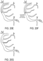
- FIGS. 20A-20G an example method for using the catheter 10 described in the present disclosure for accessing a difficult to reach side branch is shown.
- the difficult to reach side branch is in an atherosclerotic right coronary artery, as shown in FIG. 2 OA.
- a surgeon positions a guidewire to enter the right coronary artery, but cannot access the side branch, as shown in FIG. 20B .
- the microcatheter is tracked over the guidewire, as shown in FIG. 20C .
- the microcatheter is in the correct orientation for angulating the guidewire into the side branch, as indicated by the "C" shaped marker facing towards the side branch.
- the orientation rod is inserted into the microcatheter to re-orient the microcatheter until the "C" shaped marker faces towards the side branch.
- the guidewire is then pulled back inside the microcatheter until just the distal tip of the guidewire protrudes out of the opening, as shown in FIG. 20E .
- the expandable membrane of the deflection member is inflated to angulate the distal tip of the guidewire, which can then be advanced to enter the side branch, as shown in FIG. 2 OF.
- the microcatheter can either be advanced over the guidewire, or replaced with a different catheter, as shown in FIG. 20G .
- the configuration can be constructed to maintain the outer dimensions of a microcatheter, and will have a lower risk of causing harm to the artery or the subintimal space when used in the coronary arteries. That is, the deflection member 22 and other components of the catheter 10 described in the present disclosure are located within the catheter shaft 12, and the dimensions of these components can thus be sized so as not to exceed the microcatheter outer diameter.
- the ability of the catheter 10 to direct the guidewire out of the distal tip also allows for the catheter 10 to be advanced across a lesion without requiring the catheter 10 to be replaced.
- the catheter 10 described in the present disclosure can enable cardiologists to successfully perform percutaneous coronary interventions for complex chronic total occlusions.
- the catheter 10 can allow for an alternative method for directing a guidewire from the subintimal space into the true lumen that can reduce procedural costs and have a lower risk of complications as compared to current devices.
- Another advantage is that because the catheter 10 stays in place throughout the subintimal entry, little to no blood will track through the subintimal plane of tissue, which can otherwise occur when the a device (e.g., the CrossBoss described above] is removed and replaced with another device (e.g., the Stingray described above].
- the subintimal space will be prevented from filling up with blood and compressing the true lumen.
- the subintimal entry is made easier because the true lumen beyond the CTO is maintained. If the true lumen is compressed by blood tracking in the subintimal space, the distal lumen may become very difficult to visualize.
Landscapes
- Health & Medical Sciences (AREA)
- Life Sciences & Earth Sciences (AREA)
- Biophysics (AREA)
- Pulmonology (AREA)
- Engineering & Computer Science (AREA)
- Anesthesiology (AREA)
- Biomedical Technology (AREA)
- Heart & Thoracic Surgery (AREA)
- Hematology (AREA)
- Animal Behavior & Ethology (AREA)
- General Health & Medical Sciences (AREA)
- Public Health (AREA)
- Veterinary Medicine (AREA)
- Media Introduction/Drainage Providing Device (AREA)
Description
- This application claims the benefit of
U.S. Provisional Patent Application Serial No. 62/556,610, filed on September 11, 2017 - Chronic total occlusions (CTO] can be found in coronary angiography, occurring in approximately 18-33% of patients with documented coronary artery disease. Percutaneous revascularization (angioplasty] is attempted in less than 10% of CTOs. Approximately 25% of cases undergo bypass surgery, while the majority (approximately 65%] are treated medically. The main reasons for not attempting percutaneous revascularization include the frequent presence of multi-vessel disease, and the complexity and time requirements of performing these technically challenging percutaneous procedures.
- About 70% of percutaneous revascularization procedures are successful.
This is primarily due to the difficulty in crossing the occlusion with guidewires in the antegrade direction. A challenge is crossing the fibrotic and often calcified material that is occluding the artery and then re-entering the true lumen beyond the occluded segment. In some cases, the guidewire immediately re-enters the true lumen at the end of the CTO (just past the distal end], which is known as true-true crossing. However, in many cases, the guidewire cannot cross the occlusion, but is in a subintimal position after the occlusion and has to re-enter the true lumen further downstream - so called true to false to true. In some cases, downstream re-entry can be done by reshaping the tip of CTO specialty guidewires advanced through a central lumen microcatheter (such as finecross or corsair] and directing the guidewire back into the true lumen. Also, angulated microcatheters can be used, but control of the angle of the tip can be challenging in the subintimal space. - More recently, a specialized CTO device has been introduced that first involves advancing a catheter (known as the CrossBoss], which is a proximal torque device that utilizes bidirectional rotation with a fast-spin technique, in order to advance across the occlusion as the spin reduces the push required. Although this catheter can be advanced within the luminal space, it is usually advanced within the subintimal space and then the CrossBoss catheter is replaced with a special flat balloon that has two holes at different orientations (Stingray balloon] through which the operator advances a very stiff guidewire (Stingray wire] to re-enter the artery. This is a technically challenging procedure that requires extensive training and has been restricted so far to highly expert operators.
- Subintimal positioning of the guidewire (i.e. inside the wall of the coronary artery rather than the true lumen] after crossing the occlusion is a major problem and common failure more in CTO PCI, and highlights the need for additional options to facilitate re-entry into the true lumen of the artery after the occlusion.
US patent application No. 2013/072957 A1 discloses a catheter for recanalizing a blood vessel having an occlusion therein via a subintimal pathway. The catheter includes a catheter shaft having an inflatable balloon mounted to the distal end portion of the catheter shaft. A flexible tubular member extends from the catheter shaft and along an exterior of the inflatable balloon Inflation of the inflatable halloon deflects the flexible tubular member into a deflected configuration away from a longitudinal axis of the catheter shaft to effect re-entry into the true lumen distal of the occlusion.
International patent application publication No.WO2011/025855A2 discloses a method for thermal bonding of an inverted balloon neck on a catheter, including placing an inverted balloon neck on a shaft of a catheter, and characterized by applying heat at an internal hollow of the shaft where the inverted balloon neck is placed, while applying internal pressure to attach an external surface of the shaft (86) to the inverted balloon neck.
US patent application No. 2013/006167A1 discloses a method and apparatus for crossing an obstruction in a tubular member, and more particularly to a medical device method for crossing of a chronic occlusion in a subintimal or interstitial space of an artery. - The present invention is defined in
independent claim 1 and subsequent dependent claims 2 - 15. - The present disclosure addresses the aforementioned challenges by providing a catheter device designed for lumen re-entry, which may be used for percutaneous CTO revascularization and other applications, such as angioplasty procedures where it can be challenging to position a guidewire in a side branch vessel with a difficult angulation.
- It is an aspect of the present disclosure to provide a catheter that includes a catheter shaft having a tubular wall that extends from a proximal end to a distal end along a longitudinal axis to define a lumen. The tubular wall having formed therein an inner lumen that extends from the proximal end to the distal end of the catheter shaft. The catheter device also includes a deflection member coupled to the distal end of the catheter shaft and in fluid communication with the inner lumen such that fluid provided to the inner lumen causes the deflection member to expand from a first volume to a second volume that is larger than the first volume. When the deflection member is in the second volume, it extends from a surface of the tubular wall towards the longitudinal axis of the catheter shaft to provide a surface for deflecting an interventional device extending through the lumen and outward from the distal end of the catheter shaft at a deflection angle.
- The foregoing and other aspects and advantages of the disclosure will appear from the following description. In the description, reference is made to the accompanying drawings which form a part hereof, and in which there is shown by way of illustration a preferred embodiment of the disclosure. Such embodiment does not necessarily represent the full scope of the disclosure, however.
-
-
FIG. 1A is a cross sectional view of an example of a distal portion of a catheter device having an expandable member; - FIG. IB is a cross sectional view of the example catheter device of
FIG. 1A in which a wire is positioned therethrough; -
FIGS. 2A-2D show example configurations of deflection members that can be used with the catheter device described in the present disclosure. -
FIG. 3 is an axial cross-sectional view of an example of a distal portion of the catheter device ofFIG. 1A having an expandable member at a first volume; -
FIG. 4 is an axial cross-sectional view of an example of a distal portion of the catheter device ofFIG. 1A having an expandable member at a second volume; -
FIG. 5 is a cross-sectional view of another example of a distal portion of a catheter device having an expandable member; -
FIG. 6 is a cross sectional view of the example catheter device ofFIG. 3 in which a wire is positioned therethrough; -
FIG. 7 is a perspective view of the example catheter device ofFIG. 3 -
FIG. 8 is a cross-sectional view of another example of a distal portion of a catheter device having an expandable member; -
FIG. 9 is a perspective view of an example marked portion of any of theFIGS. 1 to 8 positioned in which a "C" shape is visible; -
FIG. 10 is an example of a medical image in which the "C" shape ofFIG. 9 is visible; -
FIG. 11 is a perspective view of an example marked portion of any of the
FIGS. 1 to 8 positioned in which a "Z" shape is visible; -
FIG. 12 is an example of a medical image in which the "Z" shape ofFIG. 11 is visible; -
FIG. 13A is a cross-sectional view of an example of a catheter device configured to interface with a catheter realignment system; -
FIG. 13B is a cross-sectional view of the example catheter device of FIG. 16A having a rod fed therethrough; -
FIG. 14A is a cross-sectional view of an example of a catheter device configured to interface with a catheter realignment system; -
FIG. 14B is a cross-sectional view of the example catheter device of FIG. 17A having a rod fed therethrough; -
FIG. 15A is a cross-sectional view of an example of a catheter device configured to interface with a catheter realignment system; -
FIG. 15B is a cross-sectional view of the example catheter device of FIG. 18A having a rod fed therethrough; -
FIG. 16 is a perspective view of an example of a proximal end of a catheter realignment mechanism having a handle and a rod; -
FIG. 17 is a perspective view of another example of a proximal end of a catheter realignment mechanism having a handle and a rod; -
FIG. 18 is a perspective view of another example of a proximal end of a catheter realignment mechanism having a handle and a rod; -
FIGS. 19A-19G show the steps of an example subintimal re-entry procedure using an example of a catheter described in the present disclosure; and -
FIGS. 20A-20G show the steps of an example procedure for accessing a difficult side-branch using an example of a catheter described in the present disclosure. - By way of overview and introduction, a catheter device that can provide subintimal orientation and re-entry into a lumen is generally illustrated in
FIGS. 1-18 . As will be described, one advantageous clinical use of the catheter device is treatment of chronic total occlusions ("CTO"]. The catheter device can also be used for other vascular treatment applications, such as the placement of stents and angioplasty balloons, deflection of guidewires into angulated side branches from an intraluminal position, orientation of a guidewire at the beginning of occlusion to engage a CTO proximal to the CTO and at an angle that is not parallel to the artery, and non-vascular treatment applications. Generally, the catheter device can include an orientation subsystem and a re-entry subsystem. Embodiments of the re-entry subsystem will be described with respect toFIGS. 1-8 . Embodiments of the orientation subsystem will be described with respect toFIGS. 9-18 . - Referring now to
FIGS. 1A and 1B , thecatheter 10 includes a catheter shaft
12 extending from aproximal end 14 to adistal end 16 along alongitudinal axis 18 to define alumen 20. Adeflection member 22 is coupled to theshaft 12 at thedistal end 16 of thecatheter 10. Thedeflection member 22 generally includes an expandable membrane that when filled with a fluid expands from a first volume (e.g., a deflated volume] to a second volume (e.g., an inflated or expanded volume]. When expanded to the second volume, thedeflection member 22 provides a surface for deflecting a guidewire, or other interventional device, extending through thelumen 20 outward through adistal opening 24 of thecatheter shaft 12. As will be described below, the expanded volume of thedeflection member 22 provides a surface that will deflect the guidewire, or other interventional device, a deflection angle, θ , when exiting theopening 24 at thedistal end 16 of thecatheter 10. - The wall of the
catheter shaft 12 has formed therein aninner lumen 26 extending from theproximal end 14 to thedistal end 16 of thecatheter 10. Theinner lumen 26 receives ahypotube 28 that is in fluid communication with thedeflection member 22. Thedeflection member 22 generally spans anaperture 30 formed as the distal end of theinner lumen 26, or anyhypotube 28 provided to theinner lumen 26. Theaperture 30 can be formed in the distal end of theinner lumen 26, as shown inFIGS. 1A and IB, or alternatively can be formed along the outer surface of theinner lumen 26 and through thecatheter shaft 12 such that thedeflection member 12 can be operated in a side-firing arrangement into theinterior lumen 20 of thecatheter shaft 12. Providing a fluid to thehypotube 28 causes thedeflection member 22 to expand from the first volume to the second volume. By controlling the amount of fluid provided to thedeflection member 22 via thehypotube 28, the second volume, and thereby the deflection angle, Θ , provided by thedeflection member 22, can be similarly controlled. Thus, by controlling the expanded volume of thedeflection member 22, a guidewire, or other interventional device, can be deflected into the true lumen of a blood vessel when thecatheter 10 is positioned in the subintimal space. - In some other embodiments, more than one
deflection member 22 can be provided at thedistal end 16 of thecatheter 10. In these configurations, a similar number ofinner lumens 26 are formed in the wall of thecatheter shaft 12 such that adifferent hypotube 28 may be provided to eachinner lumen 26 to be in fluid communication with one of thedeflection members 22. - In some embodiments, the wall of the
catheter shaft 12 does not include aninner lumen 26; rather, thehypotube 28 is provided to the interior surface of thelumen 20 of thecatheter shaft 12. In such configurations, it will be appreciated that more than one hypotube 28 can be similarly provided to the interior surface of thelumen 20 of thecatheter shaft 12. It will also be appreciated that in some embodiments ahypotube 28 can be provided to both aninner lumen 26 formed in the wall of thecatheter shaft 12, and to the interior surface of thelumen 20 of thecatheter shaft 12 itself. - The wall of the
catheter shaft 12 can be chamfered or beveled such that the wall slopes proximally toward thedistal opening 24 of thecatheter 10, thereby defining anangled surface 32. Theangled surface 32, in turn, defines a maximum deflection angle at which a guidewire, or other interventional device, can be deflected upon exiting theopening 24 at thedistal end 16 of thecatheter 10. In some configurations, the exterior surface of thecatheter shaft 12 may be inwardly tapered distal to ataper line 36 towards thedistal end 16 of thecatheter 10. - As mentioned above, and as shown in
FIGS. 1A and IB, thecatheter 10 can receive aguidewire 34 that can be fed through thelumen 20 from theproximal end 14 to thedistal end 16 of thecatheter 10. Theguidewire 34 can be directed through theopening 24 at thedistal end 16 of thecatheter 10 via contact with thedeflection member 22 and theangled surface 32 of thecatheter shaft 12. That is, theguidewire 34 is deflected by contact with thedeflection member 22 so as to extend outward from thedistal opening 24 at the deflection angle. - The
deflection member 22 is generally constructed as an expandable membrane that spans theaperture 30 in thecatheter shaft 12 formed by theinner lumen 26. In some other configurations, thedeflection member 22 can be constructed as an expandable membrane that spans the opening of thehypotube 28. That is, thedeflection member 22 can be coupled to thecatheter shaft 12 or to thehypotube 28. As described above, fluid is provided to thedeflection member 22 via thehypotube 28 to expand the deflection member from a first volume to a second volume. Thedeflection member 22 can have a partially spherical shape; although, other shapes can also be implemented, such as partially ellipsoidal shapes and the like. Thedeflection member 22 can extend outwardly from thedistal end 16 of thecatheter 10 along a direction perpendicular, or nearly perpendicular, to theangled surface 32 of thecatheter shaft 12. - In some embodiments, the
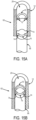
deflection member 22 can be constructed as an extruded sleeve that spans theaperture 30 in thecatheter shaft 12 formed by theinner lumen 26. Alternatively, the extruded sleeve can span a first aperture that is formed in thehypotube 28, which is aligned with a suitable second aperture in thecatheter shaft 12, such asaperture 30. An example of this configuration in an undeployed state is shown inFIG. 2A and in a deployed state inFIG. 2B . In this example, theaperture 30 in thecatheter shaft 12 formed by theinner lumen 26 terminates on the inner surface of thecatheter shaft 12 such that thedeflection member 22 will be deployed in a side-firing configuration. Thedeflection member 22 is also shown in this example as a balloon that is inflated when fluid is provided through thehypotube 28 to the interior volume of thedeflection member 22 in its undeployed state. As noted, thedeflection member 22 in this example can be constructed as anextruded sleeve 50. Thedeflection member 22 can also be constructed by dipping thecatheter shaft 12 orhypotube 28 in a suitable material to form thedeflection member 22 in its undeployed state. Thedeflection member 22 can be composed of silicon, polyurethane, silicone polypropylene , PEBAX® (Arkema; Colombes, France], or other suitable expandable material, which may include a polymer, elastomer, or so on. - In some other embodiments, the
deflection member 22 can be constructed as apatch 52 made by an extruded sleeve that spans theaperture 30 in thecatheter shaft 12 formed by theinner lumen 26. Alternatively, thepatch 52 can span a first aperture that is formed in thehypotube 28, which is aligned with a suitable second aperture in thecatheter shaft 12, such asaperture 30. Thepatch 52 can also be formed by dipping thecatheter shaft 12 orhypotube 28 in an expandable material that spans theaperture 30 in the catheter shaft, or an aperture formed in thehypotube 28. An example of this configuration is shown in an undeployed state inFIG. 2C and in a deployed state inFIG. 2D . In this example, theaperture 30 in thecatheter shaft 12 formed by theinner lumen 26 terminates on the inner surface of thecatheter shaft 12 such that thedeflection member 22 will be deployed in a side-firing configuration. Thepatch 52 can span a portion of the circumference of thecatheter shaft 12 orhypotube 28, as shown in FIG. 21C. Thedeflection member 22 is also shown in this example as a balloon that is inflated when fluid is provided through thehypotube 28 to the interior volume of thedeflection member 22 in its undeployed state. As noted, thedeflection member 22 in this example can be constructed as apatch 52 made by an extruded sleeve or by dipping thecatheter shaft 12 orhypotube 28 in a suitable material to form thedeflection member 22 in its undeployed state. Thedeflection member 22 can be composed of silicon, polyurethane, silicone polypropylene, PEBAX® (Arkema; Colombes, France], or other suitable expandable material, which may include a polymer, elastomer, or so on. - As described above, when a fluid is provided to the
deflection member 22 via thehypotube 28, thedeflection member 22 expands from the first volume to a second volume. When thedeflection member 22 has the second volume it partially extends into theopening 24 at thedistal end 16 of thecatheter 10, thereby providing a surface that will deflect a guidewire, or other interventional device, passing through theopening 24 at thedistal end 16 of thecatheter 10. As one non-limiting example, when thedeflection member 22 has the first volume, thedeflection member 22 has a substantially flat shape. That is, thedeflection member 22 can be relatively flat against theangled surface 32 of thecatheter shaft 12. In some other embodiments, thedeflection member 22 can be partially protruding from, or partially recessed relative to, theangled surface 32 of thecatheter shaft 12. As the pressure supplied to thedeflection member 22 by the fluid is decreased, thedeflection member 22 can begin to compress and transition from the expanded shape at the second volume to the flatter shape against theangled surface 32 at the first volume. It should be appreciated that thedeflection member 22 can be partially expanded, thereby expanding thedeflection member 22 into an intermediate position. - In some embodiments, the
catheter 10 is constructed to be a microcatheter.
As one example, thecatheter 10 can be constructed as a microcatheter for use in coronary arteries. Thus, in some non-limiting examples, thecatheter 10 can be sized at 4.5 Fr (1.5 mm] or less. As another example, thecatheter 10 can be constructed to be a microcatheter for use in peripheral arteries, which can allow a larger outer diameter than in coronary microcatheter implementations. - Referring to
FIGS. 3 and 4 , a view looking down thecatheter shaft 12 from thedistal end 16 of thecatheter 10 is shown with thedeflection member 22 at the first volume (FIG. 3 ] and at the second volume (FIG. 4 ]. As shown, thecatheter shaft 12 can be a tubular structure that defines thelumen 20 within the tubular structure of thecatheter shaft 12. Thecatheter shaft 12 is generally composed of a medical device class VI approved polymer material, such as, for example, polyethylene terephthalate ("PET"]; however, other polymer materials could also be employed, such as other related PET formulations, polyethylene naphthalate ("PEN"], polyether ether ketone ("PEEK"], and polyether block amide ("PEBA"], such as PEBAX® (Arkema; Colombes, France]. - In some embodiments, the catheter can be composed of more than one material. As one example, the catheter shaft can have first layer composed of a first material and a second layer composed of a second material. In such embodiments, the first layer can correspond to the inner surface of the
catheter shaft 12 and the second layer can correspond to the outer surface of thecatheter shaft 12. The first layer can be thin, such as 0.001", and the second layer can be molded around the first layer and anyhypotubes 28 positioned in the wall of thecatheter shaft 12. As one benefit, this two- layered composition can facilitate creating a varied outer diameter for thecatheter shaft 12, such as creating a tapered outer surface for thecatheter shaft 12, as described above. In these embodiments, thedeflection member 22 can be molded into the first layer. In other embodiments, thedeflection member 22 can be formed by applying a thin membrane (e.g., a thin membrane of latex plastic or other such material] across ahypotube 28. - Referring to
FIGS. 5 and 6 , another example of acatheter 10 of the present disclosure is illustrated. In this example, thecatheter 10 generally includes acatheter shaft 12 extending from aproximal end 14 to adistal end 16 along alongitudinal axis 18 to define alumen 20. In this example, thecatheter 10 is generally constructed such that thecatheter shaft 12 includes a singleinner lumen 26. As shown, theinner lumen 26 is generally positioned on afirst side 38 of thecatheter shaft 12. In some configurations, thesecond side 40 of thecatheter shaft 12 can have a thinner outer wall than thefirst side 38. As mentioned above, in some embodiments thehypotube 28 may be provided to the interior surface of thelumen 20 of thecatheter shaft 12 rather than aninner lumen 26 formed in the wall of thecatheter shaft 12. - The
catheter shaft 12 can be constructed to have an extendedportion 42 of the wall of thecatheter shaft 12 that extends distally beyond theopening 24. As shown, theextended portion 42 of the wall of thecatheter shaft 12 extends more distal on thefirst side 38 of the catheter shaft. The portion of the wall of thecatheter shaft 12 that does not include theextended portion 42 may be tapered to a thinner thickness than an opposing portion of the wall of thecatheter shaft 12. Theextended portion 42 of thecatheter shaft 12 can span one-half of a circumference of thecatheter shaft 12, or may span more or less than one-half of the circumference of thecatheter shaft 12. - In these embodiments, the
inner lumen 26 terminates in the extendedportion 42 of thecatheter shaft 12 without opening to thedistal end 16 of thecatheter shaft 12. However, anaperture 30 is formed on the inner surface of thecatheter shaft 12, such that theinner lumen 26 is open to the inner surface of thecatheter shaft 12 by way of theaperture 30. Thedeflection member 22 in this configuration can be coupled to the inner surface of thecatheter shaft 12 and can be made to span theaperture 30 such that thedeflection member 22 is in fluid communication with ahypotube 28 provided to theinner lumen 26. Thedeflection member 22 can have a generally hemi-spherical shape that provides adeflection member 22 that is "side-firing" in the sense that thedeflection member 22 expands into thelumen 20 of thecatheter shaft 12 towards thelongitudinal axis 18 of thecatheter 10 when expanding from the first volume to the second volume. - The
deflection member 22 is coupled to theaperture 30, such that theaperture 30 provides fluid communication between the deflection member and thehypotube 28 positioned in theinner lumen 26 to provide a fluid to thedeflection member 22. The fluid provided to thedeflection member 22 can facilitate expansion of thedeflection member 22 to the second volume as described above. Thedeflection member 22 at the second volume partially extends into thedistal opening 24 of thecatheter 10 to provide a surface that will deflect a guidewire or other interventional device extending through thelumen 20 of thecatheter shaft 12 by a projection angle, Θ . At the first volume, thedeflection member 22 can have a substantially flat shape. As fluid is removed from thedeflection member 22 its volume will decrease again from the second volume to the first volume. It should be appreciated that thedeflection member 22 can be partially expanded, thereby expanding thedeflection member 22 to an intermediate volume. - One example of the embodiment of the
catheter 10 as described above can be sized at 4.5 Fr (1.5 mm]. In such embodiments, thecatheter 10 can be a referred to as a microcatheter. In some implementations, thecatheter 10 may be sized for use in coronary arteries, and in some other implementations thecatheter 10 may be sized for use in peripheral arteries. - In another embodiment, the
catheter shaft 12 can be constructed to be angled at itsdistal end 16, as shown inFIG. 7 , such that thecatheter shaft 12 extends distally farther on oneside 41 than on theother side 43 forming a sloped outer surface to thedistal end 16 of thecatheter shaft 12. In these instances, theinner lumen 26 may terminate within the wall of thecatheter shaft 12. Like the embodiments described with respect toFIGS. 5 and 6 , an inward facingaperture 30 is formed in the wall of thecatheter shaft 12 to provide fluid communication between theinner lumen 26 and adeflection member 22 coupled to theaperture 30. As described above, ahypotube 28 can be provided in theinner lumen 26, or thelumen 20 of thecatheter shaft 12, to facilitate providing a fluid to thedeflection member 22 to adjust the volume of thedeflection member 22 between the first volume and the second volume. In the configuration shown inFIG. 7 , thedeflection member 22 is arranged opposite thelower side 43 of thecatheter shaft 12 at itsdistal end 16. - In another embodiment of the
catheter 10, a positioningmember 44 can be coupled to thecatheter shaft 12 at thedistal end 16 of thecatheter 10, as shown inFIG. 8 . The positioningmember 44 can be coupled adjacent adeflection member 22, such that expanding thedeflection member 22 from a first volume to a second volume will deflect or otherwise articulate the positioningmember 44 from a first position to a second position. As an example, in the second position the positioningmember 44 can provide a surface for deflecting a guidewire or other interventional device by a deflection angle. - As one example of the embodiments described above, the
catheter 10 can be sized at 4.5Fr (1.5 mm]. In some implementations, thecatheter 10 may be sized for use in coronary arteries, and in some other implementations thecatheter 10 may be sized for use in peripheral arteries. - In operation, the
catheter 10 should be properly oriented within the subintimal space, so as to ensure that the guidewire, or other interventional device, extending through thelumen 20 of thecatheter 10 will be deflected back into the true lumen of the blood vessel. To this end, thecatheter 10 can be constructed to include a radiopaque orientation marker that uniquely indicates the orientation of thecatheter shaft 12 within the subintimal space. Thecatheter 10 can also include a realignment assembly that can be used to reorient thecatheter 10 while it resides in the subintimal space, such that the deflection of the guidewire, or other interventional device, will be made into the true lumen of the blood vessel. - Referring now to
FIGS. 9 and 10 , one example of aradiopaque orientation marker 60 that is disposed on thecatheter shaft 12 of thecatheter 10 is shown. Theradiopaque orientation marker 60 can be positioned on thecatheter shaft 12 proximal to ataper line 36, such as those described above. Theradiopaque orientation marker 60 is composed of a radiopaque material and generally has an asymmetrical shape around the outer surface of thecatheter shaft 12. The asymmetrical shape provides an indication of the orientation of thecatheter 10 based on the shape displayed to a user. Thecatheter 10 can be rotated as will be discussed below, and the rotation of thecatheter 10 changes a view of theradiopaque marker 60. As shown inFIGS. 9 and 10 , theradiopaque orientation marker 60 may be shaped such that when oriented in a first orientation and viewed along a particular line-of-sight theradiopaque orientation marker 60 will be displayed as a "C- shaped" object in an x-ray image. When theradiopaque orientation marker 60 is rotated to a second orientation and viewed along the same line-of-sight, theradiopaque orientation marker 60 will be displayed as a "Z-shaped" object in an x-ray image. Thus, based on the unique shape of theradiopaque orientation marker 60, a user can visualize the current orientation of the catheter in an x-ray image. It will be appreciated that theradiopaque orientation marker 60 could also be composed of a material that renders it visible in images acquired with other medical imaging modalities, such as magnetic resonance imaging. - To adjust the orientation of the
catheter 10, a realignment assembly can be implemented. As shown inFIGS. 13A and 13B , therealignment assembly 62 can generally include arod 64 that is provided to thecatheter shaft 12 of thecatheter 10. Therod 64 interfaces with a receivingportion 66 in thecatheter shaft 12, at which therod 64 becomes coupled to thecatheter shaft 12. When interfaced with the receivingportion 66 of thecatheter shaft 12, rotation of therod 64 will result in a rotation of thecatheter shaft 12, at least at thedistal end 16 of thecatheter 10, thereby providing a realignment, or reorientation, of thecatheter shaft 12. - In the embodiment shown in
FIGS. 13A and 13B , the receivingportion 66 includesprotrusions 68 disposed on the interior wall of thecatheter shaft 12. Theseprotrusions 68 create a decreased diameter of thelumen 20 of thecatheter shaft 12. Theprotrusions 68 may be curved or otherwise shaped to provide a reduced diameter of thelumen 20 of thecatheter shaft 12. Theprotrusions 68 can be semi-deformable. When therod 64 is provided to the receivingportion 66, theprotrusions 68 will contact the distal end of therod 64, thereby creating an interference fit between therod 64 and the receivingportion 66. In this arrangement, therod 64 becomes mechanically coupled to thecatheter shaft 12 such that when therod 64 is rotated it provides a rotation of thecatheter shaft 12. - In one embodiment, shown in
FIGS. 14A and 14B , the realignment assembly
62 can include arod 64 that is tapered at its distal end. The receivingportion 66 of thecatheter shaft 12 is similarly tapered to receive the taperedrod 64. The tapering of the receivingportion 66 provides a tapered fit with therod 64 such that therod 64 becomes mechanically coupled to thecatheter shaft 12 when interfaced with the receivingportion 66. As such, when therod 64 is rotated it provides a rotation of thecatheter shaft 12. - In another embodiment shown in
FIGS. 15A and 15B , therealignment assembly 62 can include arod 64 that is shaped at its distal end to mate with the receivingportion 66 of thecatheter shaft 12. For example, therod 64 and receivingportion 66 can collectively define a "lock and key" mechanism. The receivingportion 66 can include anannular stopper 70 coupled to the inner wall of thecatheter shaft 12 and having one or more notchedrecesses 72 that receive similarly shapedprotrusions 74 extending distally from the distal end of therod 64. In some configurations, such as the one shown inFIGS. 15A and 15B , the notched recesses can be mirrored curved recesses that are recessed from the proximal surface of thestopper 70 opposite each other. The keyed end of therod 64 can have a cylindricalcentral member 76 and opposingcurved protrusions 74 that are shaped to interface with therecesses 72 and theannular stopper 70. When the keyed end of therod 64 is interfaced with therecesses 72 in theannular stopper 70, therod 64 becomes mechanically coupled to thecatheter shaft 12 such that when therod 64 is rotated it provides a rotation of thecatheter shaft 12. - Referring to
FIG. 16 , at its proximal end therod 64 can have ahandle 78 that is cylindrical in shape with a tapered distal end that tapers radially inward to meet therod 64. The outer surface of thehandle 78 can feature a plurality ofribs 80 having a raised profile and extending along a length of the outer surface of thehandle 78. Therod 64 can be generally cylindrical in shape and can extend to any appropriate length to its distal end. Referring toFIG. 17 , as another example, thehandle 78 of therod 64 can be generally cone-shaped being tapered radially inward to meet therod 64 at a distal end of thehandle 78. Referring toFIG. 18 , as another example, handle 78 of therod 64 can have a proximal body 82 that is generally spherical in shape and adistal body 84 that is generally cylindrical in shape and interfaces with therod 64. - Having generally described the features of the various embodiments of the
catheter 10, a discussion of its general mode of operation is provided. By way of example, the operation of the various embodiments of thecatheter 10 will be described with respect to treatment of chronic total occlusions in a patient. Thecatheter 10 can be configured as a re-entry component for re-entering a true lumen of a patient once thecatheter 10 has been oriented at a desired orientation in the subintimal space. In percutaneous revascularization therapy, it is desirable to have thecatheter 10 positioned after the chronic total occlusionfs] prior to re-entry in order to facilitate the procedure. As noted above, it should be appreciated by those skilled in the art that thecatheter 10 can be employed for other procedures. - The
catheter 10 can be positioned in the subintimal space of a patient near an occlusion designated for treatment. Thedeflection member 22 receives fluid from ahypotube 28 disposed within theinner lumen 26 or provided to the interior surface of thelumen 20 of thecatheter shaft 12, and the fluid causes thedeflection member 22 to expand from the first volume to the second volume. The fluid supplied to thedeflection member 22 can be controlled by a user at aproximal end 14 of thecatheter 10. As one example, the fluid can be supplied via a syringe, similar to those used in balloon catheters. - When the
deflection member 22 is expanded to the second volume, it partially extends into thedistal opening 24 of thecatheter 10 to provide a surface that will deflect a guidewire or other interventional instrument by a projection angle, Θ . It will be appreciated that during a percutaneous revascularization procedure multiple different guidewires can be interchangeably used with thecatheter 10. For instance, the guidewire can be changed for a stiffer or slippery guidewire to penetrate through the subintimal tissue to facilitate reentry into the vessel lumen. The deflection surface can be positioned on an interior side of thedeflection member 22 such that when theguidewire 34 extends through thedistal opening 24 of thelumen 20 of thecatheter 10, , theguidewire 34 will make contact with and be deflected by the surface of the deflection member. Contact between the surface of thedeflection member 22 and theguidewire 34 deflects theguidewire 34 through thedistal opening 24 along the projection angle, Θ . Theguidewire 34 may also contact theangled surface 32 that provides proximal support to theguidewire 34 when deflected through thedistal opening 24. Theguidewire 34 can extend distally from thedistal end 16 of the catheter device along the projection angle, Θ . The projection angle, θ , can be determined by a user pre-operatively or during operation in order to facilitate re-entry into the true lumen beyond the occlusion and can be selectively controlled by adjusting the volume of thedeflection member 22 as needed. Thecatheter 10 can then be advanced over theguidewire 34 into the true lumen beyond the occlusion. - During revascularization therapy using the catheter devices described in the present disclosure, it is generally desirable for the user to understand an orientation of the catheter device in order to determine the proper projection angle and to ensure the catheter device is oriented properly such that the projection angle is positioned for re-entry into the true lumen. Accordingly, the
radiopaque orientation marker 60 described above and shown inFIGS. 9-12 can be used to assist in alignment of thecatheter 10. The asymmetrical shape of theradiopaque orientation marker 60 provides an indication of the orientation of thecatheter 10 based on the appearance of the shape of theradiopaque orientation marker 60 displayed in an x-ray or other medical image of thecatheter 10. - Rotation of the
catheter 10 to a desired orientation can be achieved using the realignment assembly described above. By causing rotation of therod 64 while it is interfaced with the receivingportion 66 of the catheter shaft, thecatheter 10 can be rotated between different orientations. Therod 64 can be stiff and allow for increased translation of rotation applied by a user at thehandle 78 located at the proximal end of therod 64. Therod 64 can also provide support along the length of thecatheter shaft 12 to rotate thecatheter shaft 12 without kinking. Once the desired orientation is achieved, therod 64 can be removed from thelumen 20 of thecatheter shaft 12 and then be replaced with a guidewire for re-entry into the true lumen as discussed above. - Thus, as one non-limiting example of its use, the
catheter 10 will be oriented in the proper direction beyond the occlusion using theradiopaque orientation marker 60 and theorientation rod 64. A guidewire will be advanced to the tip of thecatheter 10, beside theuninflated deflection member 22. Thedeflection member 22 will then be expanded, angling the guidewire into the vessel lumen. The guidewire will then be advanced into the true lumen beyond the occlusion. Thecatheter 10 will then be advanced over the guidewire and into the true lumen to secure the position. After the guidewire has been advanced into the distal lumen, thecatheter 10 in the subintimal space may be exchanged for a balloon catheter or different microcatheter while maintaining the wire position in the distal lumen. - As described, the
catheter 10 can be used in CTO interventions, specifically directing a guidewire from the subintimal space towards the true lumen. Thecatheter 10 can also be used for directing a guidewire down a difficult to access side branch (in narrowed but not occluded arteries], for example. - Referring now to
FIGS. 19A-19G , an example method for using thecatheter 10 described in the present disclosure for a subintimal re-entry procedure is shown. A section of an artery with a chronic total occlusion is shown inFIG 19A . A surgeon positions a guidewire to enter the subintimal space proximal to the occlusive plaque, as shown inFIG. 19B . The microcatheter is then tracked over the guidewire into the subintimal space, as shown inFIG. 19C . The microcatheter is in the correct orientation for re-entry to the true lumen, as indicated by the "C" shaped marker facing towards the true lumen. If, however, the microcatheter is tracked over the guidewire into the subintimal space and catheter is not in the correct orientation for re-entry to the true lumen, as shown inFIG. 19D and indicated by the backwards "Z" shaped marker facing towards the true lumen, the orientation rod is inserted into the microcatheter to re-orient the microcatheter until the "C" shaped marker faces towards the true lumen. The guidewire is then pulled back inside the microcatheter until just the distal tip of the guidewire protrudes out of the opening, as shown inFIG. 19E . The expandable membrane of the deflection member is then inflated to angulate the distal tip of the guidewire, which can then be advanced to re-enter the true lumen, as shown inFIG. 19F . The catheter is then advanced over the guidewire into the true lumen, as shown inFIG, 19G . Alternatively, the guidewire is advanced into the distal lumen, and the microcatheter is withdrawn and can be replaced with a different catheter - Referring now to
FIGS. 20A-20G , an example method for using the catheter
10 described in the present disclosure for accessing a difficult to reach side branch is shown. In this example, the difficult to reach side branch is in an atherosclerotic right coronary artery, as shown inFIG. 2 OA. A surgeon positions a guidewire to enter the right coronary artery, but cannot access the side branch, as shown inFIG. 20B . The microcatheter is tracked over the guidewire, as shown inFIG. 20C . In this example, the microcatheter is in the correct orientation for angulating the guidewire into the side branch, as indicated by the "C" shaped marker facing towards the side branch. If, however, the microcatheter is tracked over the guidewire and is not in the correct orientation for angulating the guidewire into the side branch, as shown inFIG. 20D and indicated by the backwards "Z" shaped marker facing towards the side branch, then the orientation rod is inserted into the microcatheter to re-orient the microcatheter until the "C" shaped marker faces towards the side branch. The guidewire is then pulled back inside the microcatheter until just the distal tip of the guidewire protrudes out of the opening, as shown inFIG. 20E . The expandable membrane of the deflection member is inflated to angulate the distal tip of the guidewire, which can then be advanced to enter the side branch, as shown inFIG. 2 OF. When the guidewire successfully accessed the side branch, the microcatheter can either be advanced over the guidewire, or replaced with a different catheter, as shown inFIG. 20G . - One advantage of the
catheter 10 described in the present disclosure is that the configuration can be constructed to maintain the outer dimensions of a microcatheter, and will have a lower risk of causing harm to the artery or the subintimal space when used in the coronary arteries. That is, thedeflection member 22 and other components of thecatheter 10 described in the present disclosure are located within thecatheter shaft 12, and the dimensions of these components can thus be sized so as not to exceed the microcatheter outer diameter. The ability of thecatheter 10 to direct the guidewire out of the distal tip also allows for thecatheter 10 to be advanced across a lesion without requiring thecatheter 10 to be replaced. - The
catheter 10 described in the present disclosure can enable cardiologists to successfully perform percutaneous coronary interventions for complex chronic total occlusions. Thecatheter 10 can allow for an alternative method for directing a guidewire from the subintimal space into the true lumen that can reduce procedural costs and have a lower risk of complications as compared to current devices. Another advantage is that because thecatheter 10 stays in place throughout the subintimal entry, little to no blood will track through the subintimal plane of tissue, which can otherwise occur when the a device (e.g., the CrossBoss described above] is removed and replaced with another device (e.g., the Stingray described above]. As a result, the subintimal space will be prevented from filling up with blood and compressing the true lumen. In turn, the subintimal entry is made easier because the true lumen beyond the CTO is maintained. If the true lumen is compressed by blood tracking in the subintimal space, the distal lumen may become very difficult to visualize. - The present invention has been described in terms of one or more preferred embodiments, and it should be appreciated that many alternatives, variations, and modifications, aside from those expressly stated, are possible and within the scope of the invention.
Claims (15)
- A catheter (10) comprising:a catheter shaft (12) having a tubular wall that extends from a proximal end (14) to a distal end (16) along a longitudinal axis (18) to define a lumen (20), the tubular wall having formed therein an inner lumen (26) that extends from the proximal end to the distal end of the catheter shaft;a deflection member (22) coupled to the distal end of the catheter shaft and in fluid communication with the inner lumen such that fluid provided to the inner lumen causes the deflection member to expand from a first volume to a second volume that is larger than the first volume;wherein when the deflection member is in the second volume it extends from a surface of the tubular wall towards the longitudinal axis of the catheter shaft to provide a surface for deflecting an interventional device extending through the lumen and outward from the distal end of the catheter shaft at a deflection angle; andwherein the distal end of the tubular wall includes an angled surface (32) that is angled from an outer surface of the tubular wall proximally towards an inner surface of the tubular wall.
- The catheter of claim 1, wherein the deflection member is in fluid communication with a hypotube (28) positioned within the inner lumen of the catheter shaft.
- The catheter of claim 1, further comprising:a flexible guidewire (34) dimensioned to be received through and conforming to a shape of the lumen and having a distal end that extends outwardly through a distal opening; andwherein the deflection member is configured to angularly displace the distal end of the flexible guidewire at the deflection angle.
- The catheter of claim 1, wherein the deflection member is coupled to the angled surface and when in the second volume expands away from the angled surface along a direction that is normal to the angled surface.
- The catheter of claim 4, further comprising a positioning member (44) rotatably coupled to the inner surface of the tubular wall proximal to the angled surface such that when the deflection member is in the first volume the positioning member is in a first position that is parallel with the longitudinal axis and when the deflection member is in the second volume the positioning member is contacted by the deflection member and articulated into a second position that is angled at the deflection angle.
- The catheter of claim 1, wherein the deflection member is coupled to an inner surface of the tubular wall and when in the second volume expands away from the inner surface of the tubular wall along a direction that is normal to the inner surface.
- The catheter of claim 1, further comprising a radiopaque orientation marker (60) disposed on an outer surface of the tubular wall and having an asymmetrical shape that indicates an orientation of the catheter to a user.
- The catheter of claim 1, further comprising a realignment assembly (62) coupled to the tubular wall such that rotation of the realignment assembly about the longitudinal axis results in a rotation of the catheter shaft about the longitudinal axis.
- The catheter of claim 8, wherein the realignment assembly comprises a receiving portion (66) formed in the tubular wall and a rod (64) that is sized to be received by the receiving portion of the tubular wall and when received by the receiving portion of the tubular wall mechanically couples the rod to the catheter shaft.
- The catheter of claim 9, wherein the receiving portion includes a tapered surface that extends from a proximal end to a distal end along the longitudinal axis and tapers from a diameter of the lumen at its proximal end to a smaller diameter at its distal end, and wherein a distal end of the rod is tapered to be received by the receiving portion.
- The catheter of claim 9, wherein the receiving portion comprises one or more deformable protrusions (68) extending outward from an inner surface of the tubular wall in order to provide an interference fit with the rod or wherein the receiving portion comprises an annular stopper (70) formed in the tubular wall and having formed therein one or more notched recesses, recesses (72), and wherein the rod has formed at its distal end one or more protrusions (74) that interface with the one or more notched recesses in the annular stopper.
- The catheter of claim 2, further comprising:a first aperture formed in the hypotube, wherein the deflection member is coupled to the hypotube at the first aperture; anda second aperture formed in the inner lumen that is aligned with the first aperture, such that when the deflection member is expanded from the first volume to the second volume the deflection member extends through the second aperture towards the longitudinal axis of the catheter shaft.
- The catheter of claim 12, wherein the first aperture is formed at the distal end of the hypotube and the second aperture is formed at the distal end of the catheter shaft or wherein the first aperture is formed on a circumference of the hypotube and directed toward the longitudinal axis of the catheter shaft, and the second aperture is formed on an inner surface of the catheter shaft and directed towards the longitudinal axis of the catheter shaft.
- The catheter of claim 12, wherein the deflection member comprises an extruded sleeve (50) that is arranged over the first aperture, wherein the extruded sleeve is composed of an expandable material or wherein the deflection member comprises a patch (52) formed over the first aperture, wherein the patch is composed of an expandable material or wherein the deflection member is constructed by dipping the hypotube in an expandable material such that the expandable material spans the first aperture.
- The catheter of claim 14, wherein the expandable material is selected from the group consisting essentially of silicon, silicone polypropylene, polyurethane, or polyether block amide.
Applications Claiming Priority (2)
| Application Number | Priority Date | Filing Date | Title |
|---|---|---|---|
| US201762556610P | 2017-09-11 | 2017-09-11 | |
| PCT/CA2018/051124 WO2019046976A1 (en) | 2017-09-11 | 2018-09-11 | Catheter device for lumen re-entry and methods for use thereof |
Publications (4)
| Publication Number | Publication Date |
|---|---|
| EP3681580A1 EP3681580A1 (en) | 2020-07-22 |
| EP3681580A4 EP3681580A4 (en) | 2021-07-28 |
| EP3681580B1 true EP3681580B1 (en) | 2025-05-14 |
| EP3681580C0 EP3681580C0 (en) | 2025-05-14 |
Family
ID=65633356
Family Applications (1)
| Application Number | Title | Priority Date | Filing Date |
|---|---|---|---|
| EP18854017.3A Active EP3681580B1 (en) | 2017-09-11 | 2018-09-11 | Catheter device for lumen re-entry |
Country Status (10)
| Country | Link |
|---|---|
| US (1) | US20200276412A1 (en) |
| EP (1) | EP3681580B1 (en) |
| JP (1) | JP7219267B2 (en) |
| KR (1) | KR102649508B1 (en) |
| CN (1) | CN111050836A (en) |
| AU (1) | AU2018328784A1 (en) |
| BR (1) | BR112020004761A2 (en) |
| CA (1) | CA3075192A1 (en) |
| IL (1) | IL273175B2 (en) |
| WO (1) | WO2019046976A1 (en) |
Families Citing this family (10)
| Publication number | Priority date | Publication date | Assignee | Title |
|---|---|---|---|---|
| JP7638539B2 (en) * | 2019-09-16 | 2025-03-04 | ミドルトン メディカル イノベーション ピーティーワイ リミテッド | Urinary catheter and method of catheterizing the bladder using an actively deflectable urinary catheter and deflection mechanism - Patents.com |
| AU2020376754B2 (en) * | 2019-10-30 | 2023-02-23 | Boston Scientific Scimed, Inc. | Endoscopic catheter device |
| US20210220609A1 (en) * | 2020-01-16 | 2021-07-22 | Biotronik Se & Co. Kg | Implantable Pressure Sensor Probe and Catheter for Implanting a Pressure Sensor Probe |
| CN113367774B (en) * | 2020-07-06 | 2022-07-19 | 杭州启明医疗器械股份有限公司 | Interventional instrument delivery system |
| WO2022069966A1 (en) | 2020-09-30 | 2022-04-07 | Baylis Medical Company Inc. | Elongated conveyance assembly has tactile feature |
| JP7627126B2 (en) * | 2021-02-22 | 2025-02-05 | テルモ株式会社 | Catheter System |
| CN115252032A (en) * | 2022-07-14 | 2022-11-01 | 重庆市人民医院 | Preformed left auricle ligation system of sacculus expansion ligation ring |
| CN115920199B (en) * | 2022-11-08 | 2025-11-28 | 上海微创旋律医疗科技有限公司 | Microcatheter |
| CN116440389B (en) * | 2023-06-20 | 2023-11-10 | 北京普益盛济科技有限公司 | Microcatheter and method for manufacturing microtubule structure |
| CN120918856A (en) * | 2024-06-26 | 2025-11-11 | 北京深瑞达医疗科技有限公司 | Intravascular system and method of delivering tubular implants |
Family Cites Families (15)
| Publication number | Priority date | Publication date | Assignee | Title |
|---|---|---|---|---|
| KR19990064208A (en) * | 1995-10-13 | 1999-07-26 | 트랜스바스큘라, 인코포레이티드 | Methods and apparatus for bypassing arterial occlusion and / or performing other transvascular processes |
| US8617231B2 (en) * | 2001-05-18 | 2013-12-31 | Boston Scientific Scimed, Inc. | Dual guidewire exchange catheter system |
| US20040039371A1 (en) * | 2002-08-23 | 2004-02-26 | Bruce Tockman | Coronary vein navigator |
| WO2006105244A2 (en) * | 2005-03-30 | 2006-10-05 | Lumend, Inc. | Catheter systems for crossing total occlusions in vasculature |
| CA2711745C (en) * | 2007-10-19 | 2016-06-07 | Barts And The London Nhs Trust | Catheter apparatus |
| US8983577B2 (en) * | 2009-02-12 | 2015-03-17 | Koninklijke Philips N.V. | System for determining the orientation of a catheter |
| GB2469073A (en) * | 2009-03-31 | 2010-10-06 | Barking Havering And Redbridge | Balloon Assisted Occlusion of Aneurysms |
| EP2470248B1 (en) * | 2009-08-28 | 2014-10-22 | Boston Scientific Limited | Inverted balloon neck on catheter |
| EP2446918A1 (en) * | 2010-10-29 | 2012-05-02 | Biotronik AG | Balloon catheter with a radially asymmetrically dilatable portion |
| US8998936B2 (en) * | 2011-06-30 | 2015-04-07 | The Spectranetics Corporation | Reentry catheter and method thereof |
| WO2013043592A1 (en) * | 2011-09-19 | 2013-03-28 | Boston Scientific Scimed, Inc. | Subintimal re-entry catheter and retrograde recanalization |
| EP2854926A1 (en) * | 2012-05-30 | 2015-04-08 | Vascular Access Technologies, Inc. | Transvascular access device and method |
| WO2014012008A1 (en) * | 2012-07-13 | 2014-01-16 | Boston Scientific Scimed, Inc. | Subintimal reentry system |
| US10433821B2 (en) * | 2013-01-08 | 2019-10-08 | Sanovas Intellectual Property, Llc | Precision directed medical instruments |
| EP3319680A4 (en) * | 2015-07-06 | 2018-12-19 | Avinger, Inc. | Self-alignment mechanism for imaging catheter and drive assembly |
-
2018
- 2018-09-11 BR BR112020004761-9A patent/BR112020004761A2/en not_active Application Discontinuation
- 2018-09-11 US US16/645,920 patent/US20200276412A1/en active Pending
- 2018-09-11 WO PCT/CA2018/051124 patent/WO2019046976A1/en not_active Ceased
- 2018-09-11 KR KR1020207010010A patent/KR102649508B1/en active Active
- 2018-09-11 IL IL273175A patent/IL273175B2/en unknown
- 2018-09-11 AU AU2018328784A patent/AU2018328784A1/en not_active Abandoned
- 2018-09-11 EP EP18854017.3A patent/EP3681580B1/en active Active
- 2018-09-11 JP JP2020514280A patent/JP7219267B2/en active Active
- 2018-09-11 CA CA3075192A patent/CA3075192A1/en not_active Abandoned
- 2018-09-11 CN CN201880058762.3A patent/CN111050836A/en active Pending
Also Published As
| Publication number | Publication date |
|---|---|
| CA3075192A1 (en) | 2019-03-14 |
| AU2018328784A1 (en) | 2020-04-16 |
| CN111050836A (en) | 2020-04-21 |
| IL273175B2 (en) | 2024-10-01 |
| BR112020004761A2 (en) | 2020-09-15 |
| IL273175B1 (en) | 2024-06-01 |
| JP7219267B2 (en) | 2023-02-07 |
| EP3681580A1 (en) | 2020-07-22 |
| EP3681580A4 (en) | 2021-07-28 |
| US20200276412A1 (en) | 2020-09-03 |
| IL273175A (en) | 2020-04-30 |
| JP2020533099A (en) | 2020-11-19 |
| KR20200053529A (en) | 2020-05-18 |
| WO2019046976A1 (en) | 2019-03-14 |
| EP3681580C0 (en) | 2025-05-14 |
| KR102649508B1 (en) | 2024-03-21 |
Similar Documents
| Publication | Publication Date | Title |
|---|---|---|
| US20200276412A1 (en) | Catheter device for lumen re-entry and methods for use thereof | |
| CN115484900B (en) | Intravascular delivery system and method for percutaneous coronary intervention | |
| US11154325B2 (en) | Apparatus and method for septal punch | |
| EP2131913B1 (en) | Lumen reentry devices | |
| US10744304B2 (en) | Inverted balloon neck on catheter | |
| CN105636531B (en) | Formable re-entry device and system and method therefor | |
| US20230398333A1 (en) | Endovascular remotely steerable guidewire catheter | |
| JP7244114B2 (en) | Pointed Needle Axial Reentry Device | |
| EP3856055B1 (en) | Apparatus for septal punch | |
| US20260123958A1 (en) | Apparatus and method for septal punch | |
| US10786656B2 (en) | Methods and devices for recanalization of occluded body vessels using a double-sided guidewire | |
| WO2015044874A1 (en) | Device for treating chronic total coronary occlusions or occlusions of other arterial regions |
Legal Events
| Date | Code | Title | Description |
|---|---|---|---|
| STAA | Information on the status of an ep patent application or granted ep patent |
Free format text: STATUS: THE INTERNATIONAL PUBLICATION HAS BEEN MADE |
|
| PUAI | Public reference made under article 153(3) epc to a published international application that has entered the european phase |
Free format text: ORIGINAL CODE: 0009012 |
|
| STAA | Information on the status of an ep patent application or granted ep patent |
Free format text: STATUS: REQUEST FOR EXAMINATION WAS MADE |
|
| 17P | Request for examination filed |
Effective date: 20200409 |
|
| AK | Designated contracting states |
Kind code of ref document: A1 Designated state(s): AL AT BE BG CH CY CZ DE DK EE ES FI FR GB GR HR HU IE IS IT LI LT LU LV MC MK MT NL NO PL PT RO RS SE SI SK SM TR |
|
| AX | Request for extension of the european patent |
Extension state: BA ME |
|
| DAV | Request for validation of the european patent (deleted) | ||
| DAX | Request for extension of the european patent (deleted) | ||
| A4 | Supplementary search report drawn up and despatched |
Effective date: 20210628 |
|
| RIC1 | Information provided on ipc code assigned before grant |
Ipc: A61M 25/092 20060101AFI20210622BHEP Ipc: A61M 25/01 20060101ALI20210622BHEP Ipc: A61M 25/14 20060101ALI20210622BHEP |
|
| GRAP | Despatch of communication of intention to grant a patent |
Free format text: ORIGINAL CODE: EPIDOSNIGR1 |
|
| STAA | Information on the status of an ep patent application or granted ep patent |
Free format text: STATUS: GRANT OF PATENT IS INTENDED |
|
| INTG | Intention to grant announced |
Effective date: 20241220 |
|
| GRAS | Grant fee paid |
Free format text: ORIGINAL CODE: EPIDOSNIGR3 |
|
| GRAA | (expected) grant |
Free format text: ORIGINAL CODE: 0009210 |
|
| STAA | Information on the status of an ep patent application or granted ep patent |
Free format text: STATUS: THE PATENT HAS BEEN GRANTED |
|
| RIN1 | Information on inventor provided before grant (corrected) |
Inventor name: CIBULSKI, GILAD Inventor name: ARDESHIRI, RAMTIN Inventor name: ABUZEID, WAEL Inventor name: STRAUSS, BRADLEY Inventor name: DI BARTOLOMEO, LINDSEY Inventor name: TENNANT, RYAN |
|
| AK | Designated contracting states |
Kind code of ref document: B1 Designated state(s): AL AT BE BG CH CY CZ DE DK EE ES FI FR GB GR HR HU IE IS IT LI LT LU LV MC MK MT NL NO PL PT RO RS SE SI SK SM TR |
|
| REG | Reference to a national code |
Ref country code: GB Ref legal event code: FG4D |
|
| REG | Reference to a national code |
Ref country code: CH Ref legal event code: EP |
|
| REG | Reference to a national code |
Ref country code: DE Ref legal event code: R096 Ref document number: 602018081994 Country of ref document: DE |
|
| REG | Reference to a national code |
Ref country code: IE Ref legal event code: FG4D |
|
| U01 | Request for unitary effect filed |
Effective date: 20250610 |
|
| U07 | Unitary effect registered |
Designated state(s): AT BE BG DE DK EE FI FR IT LT LU LV MT NL PT RO SE SI Effective date: 20250617 |
|
| PG25 | Lapsed in a contracting state [announced via postgrant information from national office to epo] |
Ref country code: ES Free format text: LAPSE BECAUSE OF FAILURE TO SUBMIT A TRANSLATION OF THE DESCRIPTION OR TO PAY THE FEE WITHIN THE PRESCRIBED TIME-LIMIT Effective date: 20250514 |
|
| PG25 | Lapsed in a contracting state [announced via postgrant information from national office to epo] |
Ref country code: NO Free format text: LAPSE BECAUSE OF FAILURE TO SUBMIT A TRANSLATION OF THE DESCRIPTION OR TO PAY THE FEE WITHIN THE PRESCRIBED TIME-LIMIT Effective date: 20250814 Ref country code: GR Free format text: LAPSE BECAUSE OF FAILURE TO SUBMIT A TRANSLATION OF THE DESCRIPTION OR TO PAY THE FEE WITHIN THE PRESCRIBED TIME-LIMIT Effective date: 20250815 |
|
| PG25 | Lapsed in a contracting state [announced via postgrant information from national office to epo] |
Ref country code: PL Free format text: LAPSE BECAUSE OF FAILURE TO SUBMIT A TRANSLATION OF THE DESCRIPTION OR TO PAY THE FEE WITHIN THE PRESCRIBED TIME-LIMIT Effective date: 20250514 |
|
| PGFP | Annual fee paid to national office [announced via postgrant information from national office to epo] |
Ref country code: GB Payment date: 20250919 Year of fee payment: 8 |
|
| PG25 | Lapsed in a contracting state [announced via postgrant information from national office to epo] |
Ref country code: HR Free format text: LAPSE BECAUSE OF FAILURE TO SUBMIT A TRANSLATION OF THE DESCRIPTION OR TO PAY THE FEE WITHIN THE PRESCRIBED TIME-LIMIT Effective date: 20250514 |
|
| PG25 | Lapsed in a contracting state [announced via postgrant information from national office to epo] |
Ref country code: RS Free format text: LAPSE BECAUSE OF FAILURE TO SUBMIT A TRANSLATION OF THE DESCRIPTION OR TO PAY THE FEE WITHIN THE PRESCRIBED TIME-LIMIT Effective date: 20250814 |
|
| PG25 | Lapsed in a contracting state [announced via postgrant information from national office to epo] |
Ref country code: IS Free format text: LAPSE BECAUSE OF FAILURE TO SUBMIT A TRANSLATION OF THE DESCRIPTION OR TO PAY THE FEE WITHIN THE PRESCRIBED TIME-LIMIT Effective date: 20250914 |
|
| U20 | Renewal fee for the european patent with unitary effect paid |
Year of fee payment: 8 Effective date: 20250924 |
|
| PG25 | Lapsed in a contracting state [announced via postgrant information from national office to epo] |
Ref country code: SM Free format text: LAPSE BECAUSE OF FAILURE TO SUBMIT A TRANSLATION OF THE DESCRIPTION OR TO PAY THE FEE WITHIN THE PRESCRIBED TIME-LIMIT Effective date: 20250514 |
|
| PG25 | Lapsed in a contracting state [announced via postgrant information from national office to epo] |
Ref country code: CZ Free format text: LAPSE BECAUSE OF FAILURE TO SUBMIT A TRANSLATION OF THE DESCRIPTION OR TO PAY THE FEE WITHIN THE PRESCRIBED TIME-LIMIT Effective date: 20250514 |
|
| PG25 | Lapsed in a contracting state [announced via postgrant information from national office to epo] |
Ref country code: SK Free format text: LAPSE BECAUSE OF FAILURE TO SUBMIT A TRANSLATION OF THE DESCRIPTION OR TO PAY THE FEE WITHIN THE PRESCRIBED TIME-LIMIT Effective date: 20250514 |
|
| PLBE | No opposition filed within time limit |
Free format text: ORIGINAL CODE: 0009261 |
|
| STAA | Information on the status of an ep patent application or granted ep patent |
Free format text: STATUS: NO OPPOSITION FILED WITHIN TIME LIMIT |
|
| REG | Reference to a national code |
Ref country code: CH Ref legal event code: L10 Free format text: ST27 STATUS EVENT CODE: U-0-0-L10-L00 (AS PROVIDED BY THE NATIONAL OFFICE) Effective date: 20260325 |
|
| 26N | No opposition filed |
Effective date: 20260217 |
|
| REG | Reference to a national code |
Ref country code: CH Ref legal event code: H13 Free format text: ST27 STATUS EVENT CODE: U-0-0-H10-H13 (AS PROVIDED BY THE NATIONAL OFFICE) Effective date: 20260504 |