EP3681385B1 - Probe for ultrasound imaging system - Google Patents
Probe for ultrasound imaging system Download PDFInfo
- Publication number
- EP3681385B1 EP3681385B1 EP18857069.1A EP18857069A EP3681385B1 EP 3681385 B1 EP3681385 B1 EP 3681385B1 EP 18857069 A EP18857069 A EP 18857069A EP 3681385 B1 EP3681385 B1 EP 3681385B1
- Authority
- EP
- European Patent Office
- Prior art keywords
- probe
- user
- finger
- hand
- grip portion
- Prior art date
- Legal status (The legal status is an assumption and is not a legal conclusion. Google has not performed a legal analysis and makes no representation as to the accuracy of the status listed.)
- Active
Links
Images









Classifications
-
- A—HUMAN NECESSITIES
- A61—MEDICAL OR VETERINARY SCIENCE; HYGIENE
- A61B—DIAGNOSIS; SURGERY; IDENTIFICATION
- A61B8/00—Diagnosis using ultrasonic, sonic or infrasonic waves
- A61B8/44—Constructional features of the ultrasonic, sonic or infrasonic diagnostic device
- A61B8/4444—Constructional features of the ultrasonic, sonic or infrasonic diagnostic device related to the probe
- A61B8/4455—Features of the external shape of the probe, e.g. ergonomic aspects
-
- A—HUMAN NECESSITIES
- A61—MEDICAL OR VETERINARY SCIENCE; HYGIENE
- A61B—DIAGNOSIS; SURGERY; IDENTIFICATION
- A61B8/00—Diagnosis using ultrasonic, sonic or infrasonic waves
- A61B8/12—Diagnosis using ultrasonic, sonic or infrasonic waves in body cavities or body tracts, e.g. by using catheters
-
- A—HUMAN NECESSITIES
- A61—MEDICAL OR VETERINARY SCIENCE; HYGIENE
- A61B—DIAGNOSIS; SURGERY; IDENTIFICATION
- A61B8/00—Diagnosis using ultrasonic, sonic or infrasonic waves
- A61B8/42—Details of probe positioning or probe attachment to the patient
- A61B8/4245—Details of probe positioning or probe attachment to the patient involving determining the position of the probe, e.g. with respect to an external reference frame or to the patient
- A61B8/4254—Details of probe positioning or probe attachment to the patient involving determining the position of the probe, e.g. with respect to an external reference frame or to the patient using sensors mounted on the probe
-
- A—HUMAN NECESSITIES
- A61—MEDICAL OR VETERINARY SCIENCE; HYGIENE
- A61B—DIAGNOSIS; SURGERY; IDENTIFICATION
- A61B8/00—Diagnosis using ultrasonic, sonic or infrasonic waves
- A61B8/44—Constructional features of the ultrasonic, sonic or infrasonic diagnostic device
- A61B8/4427—Device being portable or laptop-like
-
- A—HUMAN NECESSITIES
- A61—MEDICAL OR VETERINARY SCIENCE; HYGIENE
- A61B—DIAGNOSIS; SURGERY; IDENTIFICATION
- A61B8/00—Diagnosis using ultrasonic, sonic or infrasonic waves
- A61B8/54—Control of the diagnostic device
-
- A—HUMAN NECESSITIES
- A61—MEDICAL OR VETERINARY SCIENCE; HYGIENE
- A61B—DIAGNOSIS; SURGERY; IDENTIFICATION
- A61B8/00—Diagnosis using ultrasonic, sonic or infrasonic waves
- A61B8/08—Clinical applications
- A61B8/0833—Clinical applications involving detecting or locating foreign bodies or organic structures
- A61B8/085—Clinical applications involving detecting or locating foreign bodies or organic structures for locating body or organic structures, e.g. tumours, calculi, blood vessels, nodules
Definitions
- the invention relates to ultrasound probes for use with an ultrasound imaging system, and in particular to ultrasound probes that are sized and configured so as to be supported and readily used with one or more fingers on a single hand of a user of the imaging system, such as a clinician.
- US 2010/0305447 relates to a handheld medical imaging acoustic sensor used to provide physiological data to electronic medical systems.
- an acoustic sensor such as an ultrasound sensor
- the acoustic sensor is designed to be worn on a finger, e.g. an index finger.
- the acoustic sensor is mounted on a U-shaped bracket that is swingably mounted using a hinge on a finger sleeve.
- the U-shaped bracket can be repositioned (flipped) using e.g. the thumb and thus does not require the use of the opposite hand.
- CN 104523292 relates to a finger-type ultrasonic probe for vascular puncture.
- US 2001/0111029 relates to an ultrasound platform using a finger-mounted probe.
- US 2007/0016030 relates to a multiplanar ultrasonic vascular sensor assembly including two ultrasonic, linear transducer arrays oriented perpendicularly to each other to form a "T" configuration.
- WO 2014/156259 relates to an operating device connected to an ultrasonic diagnostic device.
- US 2005/0085731 relates to a finger probe for use in ultrasonic imaging with a plurality of independently-addressable transducer elements.
- US 5,752,517 relates to ultrasonic diagnostic probes for imaging and diagnosing organs and vessels of the body during surgery.
- the probe is configured in one embodiment to enable the user's hand to be positioned substantially horizontally with respect to (parallel to) the skin surface of the patient, thus enabling relatively accurate probe positioning (e.g., lifting, placing, pressing, etc.) and scanning operations to be performed.
- proximal refers to a direction relatively closer to a clinician using the device to be described herein
- distal refers to a direction relatively further from the clinician.
- end of a catheter placed within the body of a patient is considered a distal end of the catheter, while the catheter end remaining outside the body is a proximal end of the catheter.
- the words “including,” “has,” and “having,” as used herein, including the claims, shall have the same meaning as the word “comprising.”
- Embodiments of the present invention are generally directed to an ultrasound probe ("probe") for use with an ultrasound imaging system.
- the probe is sized and configured so as to be supported and readily used with one or two fingers on a single hand of a user of the imaging system, such as a clinician.
- This configuration enables remaining fingers on the hand of the user to be employed for other purposes, including applying traction to the skin surface of the patient proximate the imaging site, providing touch comfort to the patient, etc.
- the probe With it supported by as little as a single finger, the probe can easily be positioned by the user in a proper orientation against the skin surface during imaging procedures.
- the probe is configured in one embodiment to enable the user's hand to be positioned substantially horizontally with respect to (i.e., parallel to) the skin surface of the patient, thus enabling relatively accurate probe positioning (e.g., lifting, placing, pressing, etc.) and scanning operations to be performed.
- the probe also includes a stabilizing portion to assist in maintaining stability of the probe while on the skin surface.
- the probe is configured to be supported and manipulated by a single finger, with the finger positioned directly over a lens portion of the probe. Such a position enables the user to easily and accurately move the probe on the skin surface as to position the probe with subtle movements as desired.
- FIG. 1 shows various components of an ultrasound imaging system 10 (also referred to herein as “imaging system” or “system”), according to one embodiment.
- the system 10 includes a console 20 housing various electronic and other components necessary for processing and depicting ultrasonic images.
- the console 20 includes a touchscreen display 30 for depicting ultrasonic images and for enabling touch-based input by a clinician to control the device and its functionality.
- An ultrasound probe (“probe") 40 containing one or more transducer elements in a head 44 thereof for emitting and receiving ultrasonic signals, is operably attached to the console 20 via a cable or other suitable interface, including wireless connectivity.
- an optional cap including a hydrogel insert can be removably attached to the head 44 of the probe 40 so as to cover a lens portion thereof.
- the hydrogel insert provides an ultrasonically transparent interface between the probe head 44 and the skin surface.
- a needle guide can also be included with the cap to assist with guiding needles through the patient's skin and into the vessel being imaged by the system 10. In another embodiment, the needle guide is included on the probe itself.
- a sheath or cover can be removably placed over the probe 40 to provide a sterile barrier. Note that other ultrasound imaging devices and systems that differ from that shown here can also benefit from the embodiments described herein.
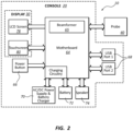
- FIG. 2 shows a block diagram of the system 10 of FIG. 1 , according to one embodiment.
- the console 20, display 30, and probe 40 are represented, as in FIG. 1 .
- the console 20 includes therein a motherboard 64 for governing system functionality and includes a processor or other general or special purpose computer, memory, storage locations, and other components for system operation.
- a beamformer 65 is also operably included with the motherboard 64 to enable ultrasonic signals to be produced, received, and processed.
- a power button 66 is included, as are USB ports 68 for interfacing with other devices.
- An external power supply 70, as well as a battery 72 and speaker 74, are provided for operation.
- the probe 40 includes a finger grip portion 110 configured to enable the user of the probe to grasp, support, and handle the probe with one or two fingers of a single hand of the user while leaving one or more fingers of the user's hand free to be used in other ways.
- the finger grip portion 110 includes two angled, protruding elements 114 extending from the opposing lateral surfaces 120A of the probe body 102. Each of the protruding elements 114 defines, together with a proximate portion of the lateral surface 102 A of the probe body 102, a concavely shaped grip surface 118 into which a user's finger is received in order to support and move the probe 40 during imaging system operation.
- the engagement of the probe 40 by the hand of the user is such that the user's hand is positioned substantially parallel with respect to the skin surface of the patient, i.e., horizontally, in a typical imaging procedure. This in turn enables the user to move the probe accurately and easily, with relatively small movements across the skin surface, which results in improved imaging results.
- the probe body 102 in this and other embodiments includes a suitable material, such as a thermoplastic. In one embodiment, the material includes R-5100 polyphenylsulfone.
- the size of the ring 124 can be configured such that the user's finger can be inserted varying distances through the ring in order to encounter a fit suitable for moving and handling the probe 40.
- the ring 124 can be sized in one or more of varying diameters.
- an insert can be removably fitted in to the ring 124 to adjust the size of the ring opening to accommodate differently sized fingers.
- all or part of the finger grip portion can be flexible/resilient so as to deform to a user's finger.
- the probe 40 in the embodiment illustrated in FIGS. 4A-4D is about 2.5 inches high, the probe head 44 about 1 inch wide, and the ring 124 about 1.5 inches wide, though other dimensions are possible for this and the other embodiments described herein.
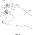
- FIG. 17 shows the probe 40 of FIGS. 4A-4D engaged with a forefinger 220 of a hand 224 of a user in one use embodiment.
- the finger grip portion 110 i.e., the ring 124, enables the user's finger to be positioned substantially co-linearly above and in a spaced-apart relationship with respect to the lens 108 of the probe head 44 when the probe is in an operable position on a horizontal skin surface of the patient 228.
- This enables the user to impart relatively fine amounts of pressure, or traction, to the skin surface via pressing down the probe 40 thereon, and provides enhanced control over the probe.
- FIG. 17 shows the probe 40 of FIGS. 4A-4D engaged with a forefinger 220 of a hand 224 of a user in one use embodiment.
- the finger grip portion 110 i.e., the ring 124
- the user's finger positioned substantially co-linearly above and in a spaced-apart relationship with respect to the lens 108 of
- FIGS. 5A-5D depict various details of the probe 40 and its finger grip portion 110 for enabling grasping, supporting, and handling of the probe with one or two fingers of a single hand of the user while leaving one or more fingers of the user's hand free to be used in other ways, according to another embodiment.
- the finger grip portion 110 includes a hook 134 defined by the body 102 of the probe 40.
- the hook 134 is approximately C-shaped and is sized in one embodiment to receive a finger of the user, such as the forefinger or middle finger, while enabling an opening for ease of finger insertion/removal.
- An inner surface of the hook 134 serves as the grip surface 118 against which the user's finger rests to enable the finger to handle and control movement of the probe 40. It is thus noted that the finger grip portion 110, i.e., the hook 134 in the present embodiment, further serves as one example of a retention portion to retain engagement of the probe 40 with the user's finger(s).
- the size of the hook 134 can be configured such that different portions of the user's finger can be inserted into the hook in order to encounter a fit suitable for moving and handling the probe 40.
- the hook 134 can be sized in one or more of varying sizes.
- an insert can be removably fitted in to the hook 134 to adjust the size thereof to accommodate differently sized fingers.
- the finger grip portion 110 i.e., the hook 134 in the embodiment of FIGS. 5A-5D , enables the user's finger to be positioned substantially co-linearly above and in a spaced-apart relationship with respect to the lens 108 of the probe head 44. This enables the user to impart relatively fine amounts of pressure, or traction, to the skin surface via pressing down the probe 40 thereon, and provides enhanced control over the probe.
- FIGS. 6A-6E depict various details of the probe 40 and its finger grip portion 110 for enabling grasping, supporting, and handling of the probe with one or two fingers of a single hand of the user while leaving one or more fingers of the user's hand free to be used in other ways, according to another embodiment.
- the finger grip portion 110 includes a tab 144 extending from one of the lateral surfaces 102A of the probe body 102.
- a terminal portion of the tab 144 includes an upwardly angled lip so as to provide the grip surface 118 on which a finger of the user, such as the forefinger, can rest.
- Another finger such as the middle finger on the same hand of the user, can engage the opposing lateral surface 102A of the probe body 102 to enable the two fingers to handle and control movement of the probe 40.
- Other fingers can be employed to grasp the probe 40, as with the other embodiments herein.
- the stabilizing portion 146 can also enable the probe 40 to be manipulated by a single finger, in one embodiment.
- a terminal free end of the leg 148 defines a notch 150, in the present embodiment, the notch configured for removably holding a portion of the cable 104 to keep it away from the hand of the user during use of the probe 40.
- the size of the cylindrical ring 154 can be configured such that the user's finger can be inserted varying distances through the ring in order to encounter a fit suitable for moving and handling the probe 40.
- the cylindrical ring 154 can be sized in one or more of varying diameters.
- an insert can be removably fitted in to the cylindrical ring 154 to adjust the size of the ring opening to accommodate differently sized fingers.
- the cylindrical ring 154 can have a varying diameter, such as being relatively wider at either end, so as to introduce freedom of movement for a finger inserted therein.
- FIGS. 8A-8D depict various details of the probe 40 and its finger grip portion 110 for enabling grasping, supporting, and handling of the probe with one or two fingers of a single hand of the user while leaving one or more fingers of the user's hand free to be used in other ways, according to another embodiment.
- the finger grip portion 110 includes the cylindrical ring 124 extending from the body 102 of the probe 40.
- the cylindrical ring 154 is sized in one embodiment to receive a finger of the user, such as the forefinger or middle finger.
- an inner cylindrical surface of the cylindrical ring 154 serves as the grip surface 118 against which the user's finger rests to enable the finger to handle and control movement of the probe 40.
- the finger grip portion 110 i.e., the cylindrical ring 154 in the present embodiment, further serves as one example of a retention portion to retain engagement of the probe 40 with the user's finger(s).
- the size of the cylindrical ring 154 can be configured such that the user's finger can be inserted varying distances through the ring in order to encounter a fit suitable for moving and handling the probe 40.
- the cylindrical ring 154 can be sized in one or more of varying diameters.
- an insert can be removably fitted in to the cylindrical ring 154 to adjust the size of the ring opening to accommodate differently sized fingers.
- the finger grip portion 110 i.e., the cylindrical ring 154 in the embodiment of FIGS. 8A-8D , enables the user's finger to be positioned substantially co-linearly above and in a spaced-apart relationship with respect to the lens 108 of the probe head 44. This enables the user to impart relatively fine amounts of pressure, or traction, to the skin surface via pressing down the probe 40 thereon, and provides enhanced control over the probe.
- the cable 104 which operably connects the probe 40 to the console 20 ( FIG. 1 ), extends from the probe body 102 at an angle from the use position of the probe (i.e., from the perspective shown in FIG. 8D ).
- This cable configuration can reduce torque on the probe 40 by the cable 104 as well as keep the cable clear of the user's hand.
- Such a configuration can be included in other of the embodiments described herein.
- FIGS. 9A-9D depict various details of the probe 40 and its finger grip portion 110 for enabling grasping, supporting, and handling of the probe with one or two fingers of a single hand of the user while leaving one or more fingers of the user's hand free to be used in other ways, according to another embodiment.
- FIGS. 9A-9D is similar to that shown in FIGS. 8A- 8D , with the addition of the stabilizing portion 146- here, the angled leg 148 similar to that shown in the embodiment of FIGS. 6A-6E .
- the particular shape of the angled leg 148 of FIGS. 9A-9D differs in shape somewhat from the angled leg of FIGS. 6A-6E , while still being configured to maintain the probe in an upright, usable position on the skin surface of the patient even when the user's hand is not contacting the probe.
- the angled leg 148 extends downward (from the perspective shown in FIG. 9D ) so as to provide a lower surface substantially flush with the lens 108 of the probe head 44. In this way, the leg 148 stabilizes the probe 40 by providing a second contacting surface for the skin, in addition to the lens 108.
- the finger grip portion 110 includes a cylindrical ring 154 extending from the main body 102 of the probe 40.
- the cylindrical ring 154 is sized in one embodiment to receive a first finger of the user, such as the middle finger.
- an inner cylindrical surface of the ring 154 serves as the grip surface 118 against which the user's finger rests to enable the finger to handle and control movement of the probe 40.
- the finger grip portion 110 i.e., the cylindrical ring 154 in the present embodiment, further serves as one example of a retention portion to retain engagement of the probe 40 with the user's finger(s).
- the size of the cylindrical ring 154 can be configured such that the user's finger can be inserted varying distances through the ring in order to encounter a fit suitable for moving and handling the probe 40.
- the cylindrical ring 154 can be sized in one or more of varying diameters.
- an insert can be removably fitted in to the cylindrical ring 154 to adjust the size of the ring opening to accommodate differently sized fingers.
- the probe body 102 further defines a protrusion 164 and a saddle 168 to provide a second grip surface 118 on which a second finger of the user's hand, such as the forefinger, can rest to further support and handle the probe 40.
- a second finger of the user's hand such as the forefinger
- the saddle 168 enables the user's finger to be positioned substantially co-linearly above and in a spaced-apart relationship with respect to the lens 108 of the probe head 44. This enables the user to impart relatively fine amounts of pressure, or traction, to the skin surface via pressing down the probe 40 thereon, and provides enhanced control over the probe.
- the probe 40 of the embodiment of FIGS. 10A-10D further includes the stabilizing portion 146 configured to maintain the probe in an upright, usable position on the skin surface of the patient even when the user's hand is not contacting the probe.
- the stabilizing portion 146 includes the cylindrical ring 154 itself, best seen in FIG. 10D .
- the cylindrical ring 154 extends downward (from the perspective shown in FIG. 10D ) so as to provide a lower surface substantially flush with the lens 108 of the probe head 44. In this way, the bottom portion of the cylindrical ring 154 stabilizes the probe 40 by providing a second contacting surface for the skin, in addition to the lens 108.
- FIGS. 11 A-l ID depict various details of the probe 40 and its finger grip portion 110 for enabling grasping, supporting, and handling of the probe with one or two fingers of a single hand of the user while leaving one or more fingers of the user's hand free to be used in other ways, according to another embodiment.
- FIGS. 11 A-l ID is similar to that shown in FIGS. 10A-10D , with the finger grip portion 110 including a cylindrical hook 174 extending from the probe body 102.
- the cylindrical hook 174 is approximately C-shaped and is sized in one embodiment to receive a finger of the user, such as the forefinger or middle finger, while enabling an opening for ease of finger insertion/removal.
- An inner surface of the hook 134 serves as the grip surface 118 against which the user's finger rests to enable the finger to handle and control movement of the probe 40.
- the cylindrical hook 174 is resilient such that it can deform a limited amount to conform to the size of the user's finger and remain connected therewith. It is thus noted that the finger grip portion 110, i.e., the hook 134 in the present embodiment, further serves as one example of a retention portion to retain engagement of the probe 40 with the user's finger(s).
- the cylindrical hook 174 can include an oval cross-sectional shape to further enhance its engagement with the user's finger.
- excess material comprising a sterile cover that is draped over the probe 40 can be inserted into the interior portion of the cylindrical hook 174 in order to increases the engagement of the cylindrical hook with the user's finger (and note that this technique can be employed in connection with the other embodiments herein, including those depicted in FIGS. 4A , 5A , 7A , 8A , 9A , 10A , and 12A .
- the cylindrical hook 174 in one embodiment can be removable as to enable cylindrical rings or other finger retention portions of different sizes/configurations to be interchanged on the probe 40.
- FIGS. 12A-12D depict various details of the probe 40 and its finger grip portion 110 for enabling grasping, supporting, and handling of the probe with one or two fingers of a single hand of the user while leaving one or more fingers of the user's hand free to be used in other ways, according to another embodiment.
- FIGS. 12A-12D is similar to that shown in FIGS. 10A-10D , with the finger grip portion 110 including the cylindrical ring 154, which further serves as the stabilizing portion 146.
- the embodiment shown in FIGS. 12A-12D includes an articulating component 178 disposed between the cylindrical ring 154 and the main portion of the probe body 102.
- the articulating component 178 includes a ball 180 included on the main portion of the probe body 102 and a corresponding socket 182 included on the cylindrical ring and sized to receive the ball therein so as to enable articulating movement between the probe head 44 and the cylindrical ring 154 through which a user's finger is received during an ultrasound imaging procedure.
- the articulating component 178 enables relative movement between the probe head 44 and the cylindrical ring, thus enabling freedom of movement of the probe 40. This is useful when it is desired to lift the lens 108 above the skin surface while desiring to keep one or more fingers on the skin surface.
- articulating and jointed structures can be employed to provide such relative movement, such as a hinge in one embodiment.
- the ball and socket configuration can be reversed in position, in one embodiment.
- FIGS. 13 A-13D depict various details of the probe 40 and its finger grip portion 110 for enabling grasping, supporting, and handling of the probe with one or two fingers of a single hand of the user while leaving one or more fingers of the user's hand free to be used in other ways, according to another embodiment.
- the probe body 102 includes a top disk 186 and a bottom disk 188 that are separated by the finger grip portion 110, here configured as an hourglass-shaped surface 184 that defines the grip surface 118.
- Two fingers of a user's single hand such as the forefinger and middle finger (though other digits could be used), can straddle the hourglass-shaped surface 184 to grasp and handle the probe 40.
- a flat side surface 190 is included on the bottom disk 188 proximate the lens 108, which is disposed on the bottom of the probe head 44, from the perspective shown in FIGS. 13C and 13D .
- a cable can extend from a cable conduit 194 at a top surface of the probe body 102.
- the probe body design shown in the present embodiment enables a finger to be positioned substantially directly over the lens 108 in a spaced-apart arrangement.
- the flat bottom surface of the bottom disk 188 best seen in FIG. 13B , serves as a stabilizing portion in the present embodiment for enabling the probe 40 to rest without assistance on the skin surface of the patient.
- FIG. 14 depicts the probe 40 according to one embodiment.
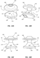
- the probe 40 here is similar to that shown in the embodiment of FIGS. 13 A-13D , but with the flat side surface 190, proximate the lens 108, being relatively larger.
- FIGS. 15A and 15B depict yet another variation of the embodiment shown in FIGS. 13A-13D , wherein the bottom disk of the probe body 102 is omitted and two chamfered surfaces 200 are defined on a bottom portion of the probe body proximate the lens 108.
- FIGS. 16A-16D depict various details of the probe 40 and its finger grip portion 110 for enabling grasping, supporting, and handling of the probe with one or two fingers of a single hand of the user while leaving one or more fingers of the user's hand free to be used in other ways, according to another embodiment.
- the probe body 102 includes a generally wedge-shaped configuration, with the lens 108 of the probe head 44 disposed on a bottom surface thereof, from the perspective shown in FIGS. 16C and 16D .
- the flat bottom surface of the probe body 102 best seen in FIG. 16B , serves as a stabilizing portion in the present embodiment for enabling the probe 40 to rest without assistance on the skin surface of the patient.
- the cable conduit 194 extends from the probe body 102 and two finger grip portions 110 are included, namely, two channels 210 that are defined by the body and are disposed adjacent the coble conduit so as to provide two concavely shaped grip surfaces 118.
- Two fingers of a single hand of the user such as the forefinger and middle finger, can be received into the channel 210 to support and handle the probe 40, while enabling other fingers of the user's hand to be used for other purposes.
- These and other probe body shapes and finger grip portion configurations are therefore contemplated.
- icons/symbols may be placed on the probe body 102 to assist a user in knowing where to place finger(s) for use of the probe 40.
Landscapes
- Life Sciences & Earth Sciences (AREA)
- Health & Medical Sciences (AREA)
- Biomedical Technology (AREA)
- Biophysics (AREA)
- Nuclear Medicine, Radiotherapy & Molecular Imaging (AREA)
- Pathology (AREA)
- Radiology & Medical Imaging (AREA)
- Engineering & Computer Science (AREA)
- Physics & Mathematics (AREA)
- Heart & Thoracic Surgery (AREA)
- Medical Informatics (AREA)
- Molecular Biology (AREA)
- Surgery (AREA)
- Animal Behavior & Ethology (AREA)
- General Health & Medical Sciences (AREA)
- Public Health (AREA)
- Veterinary Medicine (AREA)
- Ultra Sonic Daignosis Equipment (AREA)
- Transducers For Ultrasonic Waves (AREA)
Description
- The invention relates to ultrasound probes for use with an ultrasound imaging system, and in particular to ultrasound probes that are sized and configured so as to be supported and readily used with one or more fingers on a single hand of a user of the imaging system, such as a clinician.
-
US 2010/0305447 relates to a handheld medical imaging acoustic sensor used to provide physiological data to electronic medical systems. In one embodiment an acoustic sensor, such as an ultrasound sensor, is designed to be worn on a finger, e.g. an index finger. The acoustic sensor is mounted on a U-shaped bracket that is swingably mounted using a hinge on a finger sleeve. The U-shaped bracket can be repositioned (flipped) using e.g. the thumb and thus does not require the use of the opposite hand.CN 104523292 relates to a finger-type ultrasonic probe for vascular puncture.US 2001/0111029 relates to an ultrasound platform using a finger-mounted probe.US 2007/0016030 relates to a multiplanar ultrasonic vascular sensor assembly including two ultrasonic, linear transducer arrays oriented perpendicularly to each other to form a "T" configuration.WO 2014/156259 relates to an operating device connected to an ultrasonic diagnostic device.US 2005/0085731 relates to a finger probe for use in ultrasonic imaging with a plurality of independently-addressable transducer elements.US 5,752,517 relates to ultrasonic diagnostic probes for imaging and diagnosing organs and vessels of the body during surgery. Corbet et al ("A finger-worn ultrasound prove for point-of-care application", 2014 IEEE Healthcare and Innovation Conference, p.79-82) describes the SonicEye (RTM) device for "small-parts" imaging and ultrasound-guided needle procedures. Letterie et al (Am. Journal of Obstetrics & Gynaecology, vol. 187; no. 6, pages 1588-1590) relates to a "7.5 - MHz finger-grip ultrasound probe for real-time intraoperative guidance during complex reproductive surgical procedures". - Briefly summarized, embodiments of the present invention are directed to an ultrasound probe ("probe") for use with an ultrasound imaging system. In particular, the probe is sized and configured so as to be supported and readily used with as little as one finger on a single hand of a user of the imaging system, such as a clinician. This configuration enables remaining fingers on the hand of the user to be employed for other purposes, including applying traction to the skin surface of the patient proximate the imaging site and providing touch comfort to the patient. With it supported by as little as a single finger, the probe can easily be positioned by the user in a proper orientation against the skin surface during imaging procedures.
- Further, the probe is configured in one embodiment to enable the user's hand to be positioned substantially horizontally with respect to (parallel to) the skin surface of the patient, thus enabling relatively accurate probe positioning (e.g., lifting, placing, pressing, etc.) and scanning operations to be performed.
- The probe also includes a stabilizing portion to assist in maintaining stability of the probe while on the skin surface.
- In one embodiment, therefore, an ultrasound probe is disclosed, comprising a body, a lens included on head portion of the body through which ultrasound signals can be passed, a stabilizing portion extending from the body and configured to stabilize the body on a skin surface of a patient without user assistance when the lens is placed on the skin surface, the bottom surface of the stabilizing portion providing a second skin contact surface for the ultrasound probe, and a finger grip portion configured to enable a user of the probe to grasp and maneuver the probe during use thereof with no more than two fingers on a single hand of the user, the finger grip portion includes a cylindrical ring, which further serves as the stabilizing portion, and wherein an articulating component is interposed between the body and the cylindrical ring.
- These and other features of embodiments of the present invention will become more fully apparent from the following description and appended claims, or may be learned by the practice of embodiments of the invention as set forth hereinafter.
- A more particular description of the present disclosure will be rendered by reference to specific embodiments thereof that are illustrated in the appended drawings. It is appreciated that these drawings depict only typical embodiments of the invention and are therefore not to be considered limiting of its scope. Example embodiments of the invention will be described and explained with additional specificity and detail through the use of the accompanying drawings in which:
-
FIG. 1 is a perspective view of an ultrasound imaging system and included probe according to one embodiment; -
FIG. 2 is a block diagram the ultrasound imaging system ofFIG. 1 ; -
FIGS. 3A-3D are various views of an exemplary ultrasound probe; -
FIGS. 4A-4D are various views of an exemplary ultrasound probe; -
FIG. 5A-5D are various views of an exemplary ultrasound probe; -
FIGS. 6A-6E are various views of an exemplary ultrasound probe; -
FIGS. 7A-7D are various views of an exemplary ultrasound probe; -
FIGS. 8A-8D are various views of an exemplary ultrasound probe; -
FIGS. 9A-9D are various views of an exemplary ultrasound probe; -
FIGS. 10A-10D are various views of an exemplary ultrasound probe; -
FIGS. 11A-11D are various views of an exemplary ultrasound probe; -
FIGS. 12A-12D are various views of an ultrasound probe according to one embodiment; -
FIGS. 13A-13D are various views of an exemplary ultrasound probe; -
FIG. 14 is a perspective view of an exemplary ultrasound probe; -
FIGS. 15A and 15B are various views of an exemplary ultrasound probe; -
FIGS. 16A-16D are various views of an exemplary ultrasound probe; and -
FIG. 17 is a perspective view showing the hand of a user engaged with an exemplary ultrasound probe. - Reference will now be made to figures wherein like structures will be provided with like reference designations. It is understood that the drawings are diagrammatic and schematic representations of exemplary embodiments of the present invention, and are neither limiting nor necessarily drawn to scale.
- For clarity it is to be understood that the word "proximal" refers to a direction relatively closer to a clinician using the device to be described herein, while the word "distal" refers to a direction relatively further from the clinician. For example, the end of a catheter placed within the body of a patient is considered a distal end of the catheter, while the catheter end remaining outside the body is a proximal end of the catheter. Also, the words "including," "has," and "having," as used herein, including the claims, shall have the same meaning as the word "comprising."
- Embodiments of the present invention are generally directed to an ultrasound probe ("probe") for use with an ultrasound imaging system. In particular, the probe is sized and configured so as to be supported and readily used with one or two fingers on a single hand of a user of the imaging system, such as a clinician. This configuration enables remaining fingers on the hand of the user to be employed for other purposes, including applying traction to the skin surface of the patient proximate the imaging site, providing touch comfort to the patient, etc. With it supported by as little as a single finger, the probe can easily be positioned by the user in a proper orientation against the skin surface during imaging procedures.
- Further, the probe is configured in one embodiment to enable the user's hand to be positioned substantially horizontally with respect to (i.e., parallel to) the skin surface of the patient, thus enabling relatively accurate probe positioning (e.g., lifting, placing, pressing, etc.) and scanning operations to be performed.
- The probe also includes a stabilizing portion to assist in maintaining stability of the probe while on the skin surface.
- In one embodiment, which is outside the scope of the claims, the probe is configured to be supported and manipulated by a single finger, with the finger positioned directly over a lens portion of the probe. Such a position enables the user to easily and accurately move the probe on the skin surface as to position the probe with subtle movements as desired.
-
FIG. 1 shows various components of an ultrasound imaging system 10 (also referred to herein as "imaging system" or "system"), according to one embodiment. As shown, thesystem 10 includes aconsole 20 housing various electronic and other components necessary for processing and depicting ultrasonic images. Theconsole 20 includes atouchscreen display 30 for depicting ultrasonic images and for enabling touch-based input by a clinician to control the device and its functionality. An ultrasound probe ("probe") 40, containing one or more transducer elements in ahead 44 thereof for emitting and receiving ultrasonic signals, is operably attached to theconsole 20 via a cable or other suitable interface, including wireless connectivity. - In one embodiment, an optional cap including a hydrogel insert can be removably attached to the
head 44 of theprobe 40 so as to cover a lens portion thereof. The hydrogel insert provides an ultrasonically transparent interface between theprobe head 44 and the skin surface. A needle guide can also be included with the cap to assist with guiding needles through the patient's skin and into the vessel being imaged by thesystem 10. In another embodiment, the needle guide is included on the probe itself. Further details regarding the probe cap, hydrogel insert, and needle guide can be found inUS 2011/0313293 A1 entitled "Support and Cover Structures for an Ultrasound Probe Head," andUS 2012/0330159 A1 2912, entitled "Needle Guide with Selectable Aspects." In yet another embodiment, a sheath or cover can be removably placed over theprobe 40 to provide a sterile barrier. Note that other ultrasound imaging devices and systems that differ from that shown here can also benefit from the embodiments described herein. -
FIG. 2 shows a block diagram of thesystem 10 ofFIG. 1 , according to one embodiment. In detail, theconsole 20,display 30, and probe 40 are represented, as inFIG. 1 . Theconsole 20 includes therein amotherboard 64 for governing system functionality and includes a processor or other general or special purpose computer, memory, storage locations, and other components for system operation. Abeamformer 65, including suitable circuitry, is also operably included with themotherboard 64 to enable ultrasonic signals to be produced, received, and processed. Apower button 66 is included, as areUSB ports 68 for interfacing with other devices. Anexternal power supply 70, as well as abattery 72 andspeaker 74, are provided for operation. Thedisplay 30 in the present embodiment includes anLCD screen 78 or other suitable screen, and atouchscreen 80 to enable touch-based functionality via thedisplay 30. Note that thesystem 10 can include different, fewer, or more components than those listed here, including those components that enable the system to operate in a networked manner with other local or remote computing or network systems, including for instance, Wi-Fi, Ethernet, Bluetooth, and ZigBee functionality. Also, in addition to a touchscreen, other input modes can also be employed, including a keyboard or mouse input, for instance. - In operation of the
system 10, a lens portion of thehead 44 of theprobe 40 is placed against the skin of the patient so as to ultrasonically image a cross-sectional slice of a vessel, such as a vein, or other internal body tissue of the patient below the surface of the skin. Indeed, a target location of the vessel imaged by theprobe 40 is disposed a substantially vertical depth below the end of the probe. The vessel is imaged by thesystem 10 in preparation for accessing the vessel with a needle in preparation for inserting a catheter into the vessel, in one embodiment. Though shown here as a vessel, the target location can be any one of various subcutaneous locations within the body. -
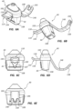
FIGS. 3A-3D depict various features of theprobe 40 including thehead 44 thereof, in accordance with one embodiment. As shown, theprobe 40 includes abody 102 defininglateral surfaces 102A and endsurfaces 102B, with thehead 44 of the probe defining a distal end of the probe body. Alens 108 is disposed at the distal end of theprobe body 102 and is configured to enable passage therethrough of ultrasonic signals. Anorientation arrow 107 is included in the illustrated embodiment to assist a user of the imaging system in determining proper needle placement through the skin surface of a patient. Acable 104 is shown extending from a proximal end of theprobe body 102 to operably connect the probe to the console 20 (FIG. 1 ), though the cable can extend from the probe in accordance with various different configurations. - In the present embodiment, the
probe 40 includes afinger grip portion 110 configured to enable the user of the probe to grasp, support, and handle the probe with one or two fingers of a single hand of the user while leaving one or more fingers of the user's hand free to be used in other ways. In the present embodiment, thefinger grip portion 110 includes two angled,protruding elements 114 extending from the opposing lateral surfaces 120A of theprobe body 102. Each of theprotruding elements 114 defines, together with a proximate portion of thelateral surface 102 A of theprobe body 102, a concavely shapedgrip surface 118 into which a user's finger is received in order to support and move theprobe 40 during imaging system operation. - In the present embodiment, the
probe 40 is placed between a forefinger (index finger) and a middle finger of a single hand of the user such that an inside portion of the forefinger engages one of the grip surfaces 118 and an inside portion of the middle finger engages the other grip surface on the opposing side of the probe. In this way, the user is able to lift, maneuver, slide, and otherwise move theprobe 40 with only two fingers during operation of theimaging system 10. Note that other fingers of the user's hand can alternatively be used to hold theprobe 40. This further enables the remaining three fingers of the user's hand to be employed in other ways during ultrasonic imaging by theprobe 40.
These other ways include, for instance, applying traction to the skin surface, touching the patient in order to impart comfort, establishing or marking a physical reference point etc. - Note that the engagement of the
probe 40 by the hand of the user is such that the user's hand is positioned substantially parallel with respect to the skin surface of the patient, i.e., horizontally, in a typical imaging procedure. This in turn enables the user to move the probe accurately and easily, with relatively small movements across the skin surface, which results in improved imaging results. Note also that theprobe body 102 in this and other embodiments includes a suitable material, such as a thermoplastic. In one embodiment, the material includes R-5100 polyphenylsulfone. - Reference is now made to
FIGS. 4A-4D , which depict various details of theprobe 40 and itsfinger grip portion 110 for enabling grasping, supporting, and handling of the probe with one or two fingers of a single hand of the user while leaving one or more fingers of the user's hand free to be used in other ways as described herein, according to another embodiment. As shown, thefinger grip portion 110 includes aring 124 defined by thebody 102 of theprobe 40. Thering 124 is sized in one embodiment to receive a finger of the user, such as the forefinger or middle finger. To that end, an inner annular surface of thering 124 serves as agrip surface 118 against which the user's finger rests to enable the finger to handle and control movement of theprobe 40. It is thus noted that thefinger grip portion 110, i.e., thering 124 in the present embodiment, further serves as one example of a retention portion to retain engagement of theprobe 40 with the user's finger(s). Note that, in this and other embodiments, the retention portion enables theprobe 40 to remain attached with the finger of the use even when the finger and/or hand of the user is lifted from the skin surface, which enables the user to perform other tasks without putting down the probe. - In one embodiment, the size of the
ring 124 can be configured such that the user's finger can be inserted varying distances through the ring in order to encounter a fit suitable for moving and handling theprobe 40. As such, thering 124 can be sized in one or more of varying diameters. In another embodiment, an insert can be removably fitted in to thering 124 to adjust the size of the ring opening to accommodate differently sized fingers. Note that in one embodiment, all or part of the finger grip portion can be flexible/resilient so as to deform to a user's finger. Note also, that theprobe 40 in the embodiment illustrated inFIGS. 4A-4D is about 2.5 inches high, theprobe head 44 about 1 inch wide, and thering 124 about 1.5 inches wide, though other dimensions are possible for this and the other embodiments described herein. -
FIG. 17 shows theprobe 40 ofFIGS. 4A-4D engaged with aforefinger 220 of ahand 224 of a user in one use embodiment. As shown, thefinger grip portion 110, i.e., thering 124, enables the user's finger to be positioned substantially co-linearly above and in a spaced-apart relationship with respect to thelens 108 of theprobe head 44 when the probe is in an operable position on a horizontal skin surface of thepatient 228. This enables the user to impart relatively fine amounts of pressure, or traction, to the skin surface via pressing down theprobe 40 thereon, and provides enhanced control over the probe. Also shown inFIG. 17 is the manner in which the hand of the user is positioned substantially parallel with respect to the skin surface of the patient, i.e., horizontally, in a typical imaging procedure. As mentioned, this enables the user to move the probe accurately and easily, with relatively small movements across the skin surface, which results in improved imaging results. - Reference is now made to
FIGS. 5A-5D , which depict various details of theprobe 40 and itsfinger grip portion 110 for enabling grasping, supporting, and handling of the probe with one or two fingers of a single hand of the user while leaving one or more fingers of the user's hand free to be used in other ways, according to another embodiment. As shown, thefinger grip portion 110 includes ahook 134 defined by thebody 102 of theprobe 40. Thehook 134 is approximately C-shaped and is sized in one embodiment to receive a finger of the user, such as the forefinger or middle finger, while enabling an opening for ease of finger insertion/removal. An inner surface of thehook 134 serves as thegrip surface 118 against which the user's finger rests to enable the finger to handle and control movement of theprobe 40. It is thus noted that thefinger grip portion 110, i.e., thehook 134 in the present embodiment, further serves as one example of a retention portion to retain engagement of theprobe 40 with the user's finger(s). - In one embodiment, the size of the
hook 134 can be configured such that different portions of the user's finger can be inserted into the hook in order to encounter a fit suitable for moving and handling theprobe 40. As such, thehook 134 can be sized in one or more of varying sizes. In another embodiment, an insert can be removably fitted in to thehook 134 to adjust the size thereof to accommodate differently sized fingers. - The
finger grip portion 110, i.e., thehook 134 in the embodiment ofFIGS. 5A-5D , enables the user's finger to be positioned substantially co-linearly above and in a spaced-apart relationship with respect to thelens 108 of theprobe head 44. This enables the user to impart relatively fine amounts of pressure, or traction, to the skin surface via pressing down theprobe 40 thereon, and provides enhanced control over the probe. - Reference is now made to
FIGS. 6A-6E , which depict various details of theprobe 40 and itsfinger grip portion 110 for enabling grasping, supporting, and handling of the probe with one or two fingers of a single hand of the user while leaving one or more fingers of the user's hand free to be used in other ways, according to another embodiment. As shown, thefinger grip portion 110 includes atab 144 extending from one of thelateral surfaces 102A of theprobe body 102. A terminal portion of thetab 144 includes an upwardly angled lip so as to provide thegrip surface 118 on which a finger of the user, such as the forefinger, can rest. Another finger, such as the middle finger on the same hand of the user, can engage the opposinglateral surface 102A of theprobe body 102 to enable the two fingers to handle and control movement of theprobe 40. Note that other fingers can be employed to grasp theprobe 40, as with the other embodiments herein. - The
probe 40 of the embodiment ofFIGS. 6A-6E further includes a stabilizingportion 146 configured to maintain the probe in an upright, usable position on the skin surface of the patient even when the user's hand is not contacting the probe. In the present embodiment, the stabilizingportion 146 includes anangled leg 148 extending from thelateral surface 102A opposite thetab 144, best seen inFIG. 6D . Theleg 148 extends downward (from the perspective shown inFIG. 6D ) so as to provide a lower surface substantially flush with thelens 108 of theprobe head 44. In this way, theleg 148 stabilizes theprobe 40 by providing a second contacting surface for the skin, in addition to thelens 108. Note that the stabilizingportion 146 can also enable theprobe 40 to be manipulated by a single finger, in one embodiment. A terminal free end of theleg 148 defines anotch 150, in the present embodiment, the notch configured for removably holding a portion of thecable 104 to keep it away from the hand of the user during use of theprobe 40. - Reference is now made to
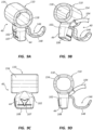
FIGS. 7A-7D , which depict various details of theprobe 40 and itsfinger grip portion 110 for enabling grasping, supporting, and handling of the probe with one or two fingers of a single hand of the user while leaving one or more fingers of the user's hand free to be used in other ways, according to another embodiment. As shown, thefinger grip portion 110 includes acylindrical ring 154 extending from themain body 102 of theprobe 40. Thecylindrical ring 154 is sized in one embodiment to receive a finger of the user, such as the forefinger or middle finger. To that end, an inner cylindrical surface of thering 154 serves as thegrip surface 118 against which the user's finger rests to enable the finger to handle and control movement of theprobe 40. It is thus noted that thefinger grip portion 110, i.e., thecylindrical ring 154 in the present embodiment, further serves as one example of a retention portion to retain engagement of theprobe 40 with the user's finger(s). - In one embodiment, the size of the
cylindrical ring 154 can be configured such that the user's finger can be inserted varying distances through the ring in order to encounter a fit suitable for moving and handling theprobe 40. As such, thecylindrical ring 154 can be sized in one or more of varying diameters. In another embodiment, an insert can be removably fitted in to thecylindrical ring 154 to adjust the size of the ring opening to accommodate differently sized fingers. In yet another embodiment, thecylindrical ring 154 can have a varying diameter, such as being relatively wider at either end, so as to introduce freedom of movement for a finger inserted therein. - The
probe 40 of the embodiment ofFIGS. 7A-7D further includes the stabilizingportion 146 configured to maintain the probe in an upright, usable position on the skin surface of the patient even when the user's hand is not contacting the probe. In the present embodiment, the stabilizingportion 146 includes thecylindrical ring 154 itself, best seen inFIG. 7D . Thecylindrical ring 154 extends downward (from the perspective shown inFIG. 7D ) so as to provide a lower surface substantially flush with thelens 108 of theprobe head 44. In this way, the bottom portion of thecylindrical ring 154 stabilizes theprobe 40 by providing a second contacting surface for the skin, in addition to thelens 108. - Reference is now made to
FIGS. 8A-8D , which depict various details of theprobe 40 and itsfinger grip portion 110 for enabling grasping, supporting, and handling of the probe with one or two fingers of a single hand of the user while leaving one or more fingers of the user's hand free to be used in other ways, according to another embodiment. - As shown, the
finger grip portion 110 includes thecylindrical ring 124 extending from thebody 102 of theprobe 40. Thecylindrical ring 154 is sized in one embodiment to receive a finger of the user, such as the forefinger or middle finger. To that end, an inner cylindrical surface of thecylindrical ring 154 serves as thegrip surface 118 against which the user's finger rests to enable the finger to handle and control movement of theprobe 40. It is thus noted that thefinger grip portion 110, i.e., thecylindrical ring 154 in the present embodiment, further serves as one example of a retention portion to retain engagement of theprobe 40 with the user's finger(s). - In one embodiment, the size of the
cylindrical ring 154 can be configured such that the user's finger can be inserted varying distances through the ring in order to encounter a fit suitable for moving and handling theprobe 40. As such, thecylindrical ring 154 can be sized in one or more of varying diameters. In another embodiment, an insert can be removably fitted in to thecylindrical ring 154 to adjust the size of the ring opening to accommodate differently sized fingers. - The
finger grip portion 110, i.e., thecylindrical ring 154 in the embodiment ofFIGS. 8A-8D , enables the user's finger to be positioned substantially co-linearly above and in a spaced-apart relationship with respect to thelens 108 of theprobe head 44. This enables the user to impart relatively fine amounts of pressure, or traction, to the skin surface via pressing down theprobe 40 thereon, and provides enhanced control over the probe. - Note in the present embodiment that the
cable 104, which operably connects theprobe 40 to the console 20 (FIG. 1 ), extends from theprobe body 102 at an angle from the use position of the probe (i.e., from the perspective shown inFIG. 8D ). This cable configuration can reduce torque on theprobe 40 by thecable 104 as well as keep the cable clear of the user's hand. Such a configuration can be included in other of the embodiments described herein. - Reference is now made to
FIGS. 9A-9D , which depict various details of theprobe 40 and itsfinger grip portion 110 for enabling grasping, supporting, and handling of the probe with one or two fingers of a single hand of the user while leaving one or more fingers of the user's hand free to be used in other ways, according to another embodiment. - As shown, the embodiment of
FIGS. 9A-9D is similar to that shown inFIGS. 8A- 8D , with the addition of the stabilizing portion 146- here, theangled leg 148 similar to that shown in the embodiment ofFIGS. 6A-6E . Note that the particular shape of theangled leg 148 ofFIGS. 9A-9D differs in shape somewhat from the angled leg ofFIGS. 6A-6E , while still being configured to maintain the probe in an upright, usable position on the skin surface of the patient even when the user's hand is not contacting the probe. As before, theangled leg 148 extends downward (from the perspective shown inFIG. 9D ) so as to provide a lower surface substantially flush with thelens 108 of theprobe head 44. In this way, theleg 148 stabilizes theprobe 40 by providing a second contacting surface for the skin, in addition to thelens 108. - Reference is now made to
FIGS. 10A-10D , which depict various details of theprobe 40 and itsfinger grip portion 110 for enabling grasping, supporting, and handling of the probe with one or two fingers of a single hand of the user while leaving one or more fingers of the user's hand free to be used in other ways, according to another embodiment. As shown, thefinger grip portion 110 includes acylindrical ring 154 extending from themain body 102 of theprobe 40. Thecylindrical ring 154 is sized in one embodiment to receive a first finger of the user, such as the middle finger. To that end, an inner cylindrical surface of thering 154 serves as thegrip surface 118 against which the user's finger rests to enable the finger to handle and control movement of theprobe 40. It is thus noted that thefinger grip portion 110, i.e., thecylindrical ring 154 in the present embodiment, further serves as one example of a retention portion to retain engagement of theprobe 40 with the user's finger(s). - In one embodiment, the size of the
cylindrical ring 154 can be configured such that the user's finger can be inserted varying distances through the ring in order to encounter a fit suitable for moving and handling theprobe 40. As such, thecylindrical ring 154 can be sized in one or more of varying diameters. In another embodiment, an insert can be removably fitted in to thecylindrical ring 154 to adjust the size of the ring opening to accommodate differently sized fingers. - The
probe body 102 further defines aprotrusion 164 and asaddle 168 to provide asecond grip surface 118 on which a second finger of the user's hand, such as the forefinger, can rest to further support and handle theprobe 40. Thus, two fingers of a user's single hand can be employed in the present embodiment to support and use theprobe 40. Thesaddle 168 enables the user's finger to be positioned substantially co-linearly above and in a spaced-apart relationship with respect to thelens 108 of theprobe head 44. This enables the user to impart relatively fine amounts of pressure, or traction, to the skin surface via pressing down theprobe 40 thereon, and provides enhanced control over the probe. - The
probe 40 of the embodiment ofFIGS. 10A-10D further includes the stabilizingportion 146 configured to maintain the probe in an upright, usable position on the skin surface of the patient even when the user's hand is not contacting the probe. In the present embodiment, the stabilizingportion 146 includes thecylindrical ring 154 itself, best seen inFIG. 10D . Thecylindrical ring 154 extends downward (from the perspective shown inFIG. 10D ) so as to provide a lower surface substantially flush with thelens 108 of theprobe head 44. In this way, the bottom portion of thecylindrical ring 154 stabilizes theprobe 40 by providing a second contacting surface for the skin, in addition to thelens 108. - Reference is now made to
FIGS. 11 A-l ID, which depict various details of theprobe 40 and itsfinger grip portion 110 for enabling grasping, supporting, and handling of the probe with one or two fingers of a single hand of the user while leaving one or more fingers of the user's hand free to be used in other ways, according to another embodiment. - As shown, the embodiment of
FIGS. 11 A-l ID is similar to that shown inFIGS. 10A-10D , with thefinger grip portion 110 including acylindrical hook 174 extending from theprobe body 102. Thecylindrical hook 174 is approximately C-shaped and is sized in one embodiment to receive a finger of the user, such as the forefinger or middle finger, while enabling an opening for ease of finger insertion/removal. An inner surface of thehook 134 serves as thegrip surface 118 against which the user's finger rests to enable the finger to handle and control movement of theprobe 40. In one embodiment, thecylindrical hook 174 is resilient such that it can deform a limited amount to conform to the size of the user's finger and remain connected therewith. It is thus noted that thefinger grip portion 110, i.e., thehook 134 in the present embodiment, further serves as one example of a retention portion to retain engagement of theprobe 40 with the user's finger(s). - Note that in one embodiment the
cylindrical hook 174 can include an oval cross-sectional shape to further enhance its engagement with the user's finger. In one embodiment, excess material comprising a sterile cover that is draped over theprobe 40 can be inserted into the interior portion of thecylindrical hook 174 in order to increases the engagement of the cylindrical hook with the user's finger (and note that this technique can be employed in connection with the other embodiments herein, including those depicted inFIGS. 4A ,5A ,7A ,8A ,9A ,10A , and12A . In addition, thecylindrical hook 174 in one embodiment can be removable as to enable cylindrical rings or other finger retention portions of different sizes/configurations to be interchanged on theprobe 40. - Also, as with the
cylindrical ring 154 of the embodiment shown inFIGS. 10A-10D , thecylindrical hook 174 of the present embodiment serves as the stabilizingportion 146, configured to maintain theprobe 40 in an upright, usable position on the skin surface of the patient even when the user's hand is not contacting the probe. - Reference is now made to
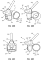
FIGS. 12A-12D , which depict various details of theprobe 40 and itsfinger grip portion 110 for enabling grasping, supporting, and handling of the probe with one or two fingers of a single hand of the user while leaving one or more fingers of the user's hand free to be used in other ways, according to another embodiment. - As shown, the embodiment of
FIGS. 12A-12D is similar to that shown inFIGS. 10A-10D , with thefinger grip portion 110 including thecylindrical ring 154, which further serves as the stabilizingportion 146. The embodiment shown inFIGS. 12A-12D includes an articulatingcomponent 178 disposed between thecylindrical ring 154 and the main portion of theprobe body 102. In detail, the articulatingcomponent 178 includes aball 180 included on the main portion of theprobe body 102 and acorresponding socket 182 included on the cylindrical ring and sized to receive the ball therein so as to enable articulating movement between theprobe head 44 and thecylindrical ring 154 through which a user's finger is received during an ultrasound imaging procedure. The articulatingcomponent 178 enables relative movement between theprobe head 44 and the cylindrical ring, thus enabling freedom of movement of theprobe 40. This is useful when it is desired to lift thelens 108 above the skin surface while desiring to keep one or more fingers on the skin surface. Note that other articulating and jointed structures can be employed to provide such relative movement, such as a hinge in one embodiment. Also, the ball and socket configuration can be reversed in position, in one embodiment. - Note that, in the present and previous embodiments discussed above, the
probe head 44,lens 108, andorientation arrow 107 are configured similar to standard probe heads so as to lend familiarity to the user in terms of placement of the probe head and lens on the skin surface and inserting needles, etc. - Reference is now made to
FIGS. 13 A-13D , which depict various details of theprobe 40 and itsfinger grip portion 110 for enabling grasping, supporting, and handling of the probe with one or two fingers of a single hand of the user while leaving one or more fingers of the user's hand free to be used in other ways, according to another embodiment. As shown, theprobe body 102 includes atop disk 186 and abottom disk 188 that are separated by thefinger grip portion 110, here configured as an hourglass-shapedsurface 184 that defines thegrip surface 118. Two fingers of a user's single hand, such as the forefinger and middle finger (though other digits could be used), can straddle the hourglass-shapedsurface 184 to grasp and handle theprobe 40. Aflat side surface 190 is included on thebottom disk 188 proximate thelens 108, which is disposed on the bottom of theprobe head 44, from the perspective shown inFIGS. 13C and 13D . A cable can extend from acable conduit 194 at a top surface of theprobe body 102. As in previous embodiments, the probe body design shown in the present embodiment enables a finger to be positioned substantially directly over thelens 108 in a spaced-apart arrangement. Note that the flat bottom surface of thebottom disk 188, best seen inFIG. 13B , serves as a stabilizing portion in the present embodiment for enabling theprobe 40 to rest without assistance on the skin surface of the patient. -
FIG. 14 depicts theprobe 40 according to one embodiment. Theprobe 40 here is similar to that shown in the embodiment ofFIGS. 13 A-13D , but with theflat side surface 190, proximate thelens 108, being relatively larger. -
FIGS. 15A and 15B depict yet another variation of the embodiment shown inFIGS. 13A-13D , wherein the bottom disk of theprobe body 102 is omitted and two chamferedsurfaces 200 are defined on a bottom portion of the probe body proximate thelens 108. These and other variations to theprobe body 102 while still enabling grasping and handling of theprobe 40 with one or two fingers but while still enabling other fingers of the user's hand to be free for other purposes, are therefore contemplated. -
FIGS. 16A-16D depict various details of theprobe 40 and itsfinger grip portion 110 for enabling grasping, supporting, and handling of the probe with one or two fingers of a single hand of the user while leaving one or more fingers of the user's hand free to be used in other ways, according to another embodiment. As shown, theprobe body 102 includes a generally wedge-shaped configuration, with thelens 108 of theprobe head 44 disposed on a bottom surface thereof, from the perspective shown inFIGS. 16C and 16D . Note that the flat bottom surface of theprobe body 102, best seen inFIG. 16B , serves as a stabilizing portion in the present embodiment for enabling theprobe 40 to rest without assistance on the skin surface of the patient. - The
cable conduit 194 extends from theprobe body 102 and twofinger grip portions 110 are included, namely, twochannels 210 that are defined by the body and are disposed adjacent the coble conduit so as to provide two concavely shaped grip surfaces 118. Two fingers of a single hand of the user, such as the forefinger and middle finger, can be received into thechannel 210 to support and handle theprobe 40, while enabling other fingers of the user's hand to be used for other purposes. These and other probe body shapes and finger grip portion configurations are therefore contemplated. - Note that the probes discussed herein are further configured to enable a sterile cover to be thereover and for elastic bands to be used to secure the cover to the probe. The probes herein are also configured to be symmetrical along at least one midline axis so as to enable both left-handed and right-handed use.
- In one embodiment, it is appreciated that icons/symbols may be placed on the
probe body 102 to assist a user in knowing where to place finger(s) for use of theprobe 40. - Embodiments of the invention may be embodied in other specific forms without departing from the scope of the invention as defined in the claims. The described embodiments are to be considered in all respects only as illustrative, not restrictive. The scope of the invention is, therefore, indicated by the appended claims rather than by the foregoing description.
Claims (8)
- An ultrasound probe (40), comprising:a body (102);a lens (108) included on a head portion (44) of the body (102) through which ultrasound signals can be passed;a stabilizing portion (146) extending from the body (102) and configured to stabilize the body on a skin surface of a patient without user assistance when the lens is placed on the skin surface, the bottom surface of the stabilizing portion providing a second skin contact surface for the ultrasound probe; anda finger grip portion (110) configured to enable a user of the probe (40) to grasp and maneuver the probe (40) during use thereof with no more than two fingers on a single hand of the user, wherein the finger grip portion (110) includes a cylindrical ring (154), which further serves as the stabilizing portion (146), and wherein an articulating component (178) is interposed between the body (102) and the cylindrical ring (154).
- The ultrasound probe as defined in claim 1, wherein the finger grip portion (110) is configured to enable the user to grasp and maneuver the probe (40) with a single finger.
- The ultrasound probe as defined in claim 1, wherein
wherein the finger grip portion (110) further includes a saddle portion (168) configured to receive a finger thereon. - The ultrasound probe as defined in any one of claims 1 to 3,
wherein the finger grip portion (110) is configured to be engaged by at least one of a forefinger and a middle finger of the hand of the user. - The ultrasound probe as defined in any one of claims 1-4, wherein at least a thumb and a finger of the hand of the user are configured to be free to use when the hand of the user is grasping the probe (40).
- The ultrasound probe as defined in any one of claims 1 to 5, wherein the articulating component (178) includes a ball and socket configuration.
- The ultrasound probe as defined in claim 1, wherein the stabilizing portion (146) is configured to maintain the body (102) of the probe (40) in an operable position without user assistance when the probe (40) is placed on the substantially horizontal skin surface of the patient.
- The ultrasound probe as defined in claim 1, wherein the finger grip portion (110) is configured to enable the hand of the user to be positioned substantially parallel with respect to the skin surface of the patient.
Priority Applications (1)
| Application Number | Priority Date | Filing Date | Title |
|---|---|---|---|
| EP25180475.3A EP4588443A3 (en) | 2017-09-13 | 2018-09-13 | Probe for ultrasound imaging system |
Applications Claiming Priority (2)
| Application Number | Priority Date | Filing Date | Title |
|---|---|---|---|
| US201762558234P | 2017-09-13 | 2017-09-13 | |
| PCT/US2018/050925 WO2019055684A1 (en) | 2017-09-13 | 2018-09-13 | Probe for ultrasound imaging system |
Related Child Applications (2)
| Application Number | Title | Priority Date | Filing Date |
|---|---|---|---|
| EP25180475.3A Division-Into EP4588443A3 (en) | 2017-09-13 | 2018-09-13 | Probe for ultrasound imaging system |
| EP25180475.3A Division EP4588443A3 (en) | 2017-09-13 | 2018-09-13 | Probe for ultrasound imaging system |
Publications (4)
| Publication Number | Publication Date |
|---|---|
| EP3681385A1 EP3681385A1 (en) | 2020-07-22 |
| EP3681385A4 EP3681385A4 (en) | 2020-11-18 |
| EP3681385B1 true EP3681385B1 (en) | 2025-07-09 |
| EP3681385C0 EP3681385C0 (en) | 2025-07-09 |
Family
ID=65630086
Family Applications (2)
| Application Number | Title | Priority Date | Filing Date |
|---|---|---|---|
| EP18857069.1A Active EP3681385B1 (en) | 2017-09-13 | 2018-09-13 | Probe for ultrasound imaging system |
| EP25180475.3A Pending EP4588443A3 (en) | 2017-09-13 | 2018-09-13 | Probe for ultrasound imaging system |
Family Applications After (1)
| Application Number | Title | Priority Date | Filing Date |
|---|---|---|---|
| EP25180475.3A Pending EP4588443A3 (en) | 2017-09-13 | 2018-09-13 | Probe for ultrasound imaging system |
Country Status (4)
| Country | Link |
|---|---|
| US (2) | US11413018B2 (en) |
| EP (2) | EP3681385B1 (en) |
| CN (1) | CN111093480A (en) |
| WO (1) | WO2019055684A1 (en) |
Families Citing this family (20)
| Publication number | Priority date | Publication date | Assignee | Title |
|---|---|---|---|---|
| CN113648551B (en) | 2013-03-08 | 2025-03-25 | 奥赛拉公司 | Device and method for multi-focus ultrasound therapy |
| CA2980446A1 (en) * | 2015-03-31 | 2016-10-06 | Marcio Marc Abreu | Wearable devices configured to support measurement and transmission apparatus |
| US11413018B2 (en) | 2017-09-13 | 2022-08-16 | Bard Access Systems, Inc. | Ultrasound finger probe |
| IL321967A (en) | 2018-11-30 | 2025-09-01 | Ulthera Inc | Systems and methods for enhancing efficacy of ultrasound treatment |
| USD1065534S1 (en) | 2020-01-03 | 2025-03-04 | Bard Access Systems, Inc. | Ultrasound finger probe |
| WO2021138442A1 (en) * | 2020-01-03 | 2021-07-08 | Bard Access Systems, Inc. | Ultrasound finger probe and methods thereof |
| US11877810B2 (en) | 2020-07-21 | 2024-01-23 | Bard Access Systems, Inc. | System, method and apparatus for magnetic tracking of ultrasound probe and generation of 3D visualization thereof |
| CN217310576U (en) | 2020-08-04 | 2022-08-30 | 巴德阿克塞斯系统股份有限公司 | Guidance system for assisting the advancement of a medical component within a patient |
| CN217907826U (en) | 2020-08-10 | 2022-11-29 | 巴德阿克塞斯系统股份有限公司 | Medical analysis system |
| US12492953B2 (en) | 2020-09-18 | 2025-12-09 | Bard Access Systems, Inc. | Ultrasound probe with pointer remote control capability |
| EP4216825B1 (en) | 2020-10-02 | 2025-08-20 | Bard Access Systems, Inc. | Ultrasound systems for sustained spatial attention |
| CN121221162A (en) | 2020-10-15 | 2025-12-30 | 巴德阿克塞斯系统股份有限公司 | Ultrasound imaging system and method for creating three-dimensional ultrasound images of a target region using the system |
| CN115670502A (en) | 2021-07-23 | 2023-02-03 | 巴德阿克塞斯系统股份有限公司 | Stabilization system for medical devices |
| JP7779040B2 (en) * | 2021-08-04 | 2025-12-03 | ニプロ株式会社 | Ultrasound diagnostic equipment |
| US12295788B2 (en) * | 2022-05-19 | 2025-05-13 | Martin Joel Pollock | Grip apparatus for ultrasound imaging transducer device |
| US12102481B2 (en) | 2022-06-03 | 2024-10-01 | Bard Access Systems, Inc. | Ultrasound probe with smart accessory |
| US12137989B2 (en) | 2022-07-08 | 2024-11-12 | Bard Access Systems, Inc. | Systems and methods for intelligent ultrasound probe guidance |
| US12564373B2 (en) | 2022-08-15 | 2026-03-03 | Bard Access Systems, Inc. | Spatially aware medical device configured for performance of insertion pathway approximation |
| IL298736B2 (en) * | 2022-12-01 | 2026-01-01 | Pulsenmore Ltd | Medical follicles assessment device with ergonomic grip |
| US12582381B1 (en) | 2025-03-17 | 2026-03-24 | Hugh Smith | Ergonomic ultrasound support |
Citations (1)
| Publication number | Priority date | Publication date | Assignee | Title |
|---|---|---|---|---|
| WO2016201006A1 (en) * | 2015-06-08 | 2016-12-15 | The Board Of Trustees Of The Leland Stanford Junior University | 3d ultrasound imaging, associated methods, devices, and systems |
Family Cites Families (72)
| Publication number | Priority date | Publication date | Assignee | Title |
|---|---|---|---|---|
| DE3219271A1 (en) | 1982-05-21 | 1983-11-24 | Siemens AG, 1000 Berlin und 8000 München | ULTRASONIC APPLICATOR |
| US4869260A (en) | 1986-05-13 | 1989-09-26 | Iowa State University Research Foundation, Inc. | Method and means for detecting pregnancy in domestic farm animal species |
| JPS63151109U (en) | 1987-03-26 | 1988-10-04 | ||
| US5195519A (en) | 1988-12-22 | 1993-03-23 | Angelsen Bjorn A J | Miniaturized mechanically-steerable ultrasonic probe |
| US5284147A (en) | 1989-05-22 | 1994-02-08 | Hitachi Medical Corporation | Ultrasonic probe to be installed on fingertip |
| USD327740S (en) | 1989-08-02 | 1992-07-07 | Terumo Kabushiki Kaisha | Ultrasonic scanning probe |
| US5088500A (en) * | 1989-11-22 | 1992-02-18 | Victor J. Wedel | Ultrasound finger probe and method for use |
| US5182972A (en) | 1991-03-28 | 1993-02-02 | Skaleski Robert A | Improved finger tip mounted holding device |
| US5152293A (en) * | 1991-07-01 | 1992-10-06 | Northwestern University | Finger-mounted intraoperative imaging device |
| US5598846A (en) | 1995-12-21 | 1997-02-04 | Hewlett-Packard Company | Rotatable ultrasound transducer finger probe |
| US5671747A (en) | 1996-01-24 | 1997-09-30 | Hewlett-Packard Company | Ultrasound probe having interchangeable accessories |
| US5752517A (en) | 1996-10-18 | 1998-05-19 | Advanced Technology Laboratories, Inc. | Intraoperative ultrasound probes for ultrasonic examination during surgery |
| US5792059A (en) | 1996-11-26 | 1998-08-11 | Esaote S.P.A. | Intraoperative probe, specifically intended for direct-contact observations |
| US5986446A (en) | 1997-02-05 | 1999-11-16 | C. Blake Williamson | Multi-meter and probe assembly and method of use |
| US5895871A (en) | 1997-07-25 | 1999-04-20 | General Electric Company | Finger controlled inspection apparatus |
| US6193709B1 (en) | 1998-05-13 | 2001-02-27 | Olympus Optical Co., Ltd. | Ultrasonic treatment apparatus |
| US6155987A (en) | 1999-02-11 | 2000-12-05 | Scherl; Michael | Assembly for removing ear wax from one's ear canal |
| US6126608A (en) | 1999-05-18 | 2000-10-03 | Pie Medical Equipment B.V. | Portable ultrasound diagnostic system with handsfree display |
| AU2001239977A1 (en) | 2000-03-02 | 2001-09-12 | Mayo Foundation For Medical Education And Research | Apparatus and method of holding and manipulating small ultrasound transducers |
| US7037270B2 (en) | 2000-03-02 | 2006-05-02 | Mayo Foundation For Medical Education And Research | Small ultrasound transducers |
| US6746402B2 (en) | 2002-01-02 | 2004-06-08 | E. Tuncay Ustuner | Ultrasound system and method |
| US7806828B2 (en) | 2002-02-05 | 2010-10-05 | Inceptio Medical Technologies, Lc | Multiplanar ultrasonic vascular sensor assembly and apparatus for movably affixing a sensor assembly to a body |
| EP1599121A4 (en) * | 2002-11-27 | 2007-10-10 | Blacktoe Medical Iii Inc | Immersible ultrasound probe and cable |
| US20050096554A1 (en) | 2002-11-27 | 2005-05-05 | Dudik Evan M. | Acoustic medical sensor for ultrasound imaging |
| US20040225217A1 (en) * | 2003-02-14 | 2004-11-11 | Voegele James W. | Fingertip ultrasound medical instrument |
| US7128720B2 (en) | 2003-06-30 | 2006-10-31 | Ethicon, Inc. | Ultrasonic finger probe |
| US20050085731A1 (en) | 2003-10-21 | 2005-04-21 | Miller David G. | Ultrasound transducer finger probe |
| US20060025690A1 (en) | 2004-07-27 | 2006-02-02 | Guigne Jacques Y | Acoustic body examination |
| US20060173331A1 (en) | 2004-11-24 | 2006-08-03 | Siemens Medical Solutions Usa, Inc. | Ergonomic transducer housing and methods for ultrasound imaging |
| GB0511008D0 (en) | 2005-05-31 | 2005-07-06 | Greater Glasgow Health Board N | Ultrasound probe |
| US8128568B2 (en) * | 2006-05-02 | 2012-03-06 | U-Systems, Inc. | Handheld volumetric ultrasound scanning device |
| US20080097215A1 (en) * | 2006-09-19 | 2008-04-24 | Kliewer Mark A | Ultrasonic probe with finger shelf |
| USD566284S1 (en) | 2006-11-09 | 2008-04-08 | Kabushiki Kaisha Toshiba | Connector for an ultrasonic probe |
| ATE530121T1 (en) * | 2006-12-18 | 2011-11-15 | Esaote Spa | ERGONOMIC HOUSING FOR AN ELECTROACOUSTIC TRANSDUCER AND ULTRASONIC PROBE HAVING SUCH A HOUSING |
| US20080306387A1 (en) | 2007-04-13 | 2008-12-11 | Schutz Ronald W | Finger mounted imaging and sensing assembly |
| WO2008131557A1 (en) | 2007-05-01 | 2008-11-06 | Urodynamix Technologies Ltd. | Apparatus and methods for evaluating physiological conditions of tissue |
| US20090163807A1 (en) | 2007-12-21 | 2009-06-25 | Sliwa John W | Finger-mounted or robot-mounted transducer device |
| USD609814S1 (en) | 2008-11-28 | 2010-02-09 | Kabushiki Kaisha Toshiba | Connector for ultrasonic probe |
| USD685482S1 (en) | 2009-04-09 | 2013-07-02 | Welch Allyn, Inc. | Cover for a probe or the like |
| US8277417B2 (en) | 2009-09-23 | 2012-10-02 | James J. Fedinec | Central venous catheter kit with line gripping and needle localizing devices |
| WO2011044421A1 (en) | 2009-10-08 | 2011-04-14 | C. R. Bard, Inc. | Spacers for use with an ultrasound probe |
| US20120197131A1 (en) | 2011-02-01 | 2012-08-02 | General Electric Company | Probe-mounted ultrasound system control interface |
| WO2013019806A2 (en) | 2011-08-01 | 2013-02-07 | University Of Florida Research Foundation Inc. | Apparatus for facilitating ultrasound-assisted needle placement for drug delivery |
| WO2013028786A2 (en) | 2011-08-22 | 2013-02-28 | Fuller Bradbury | Hand-mounted, video-guided system for treating peritonitis and other medical conditions |
| CN102968076A (en) | 2011-08-31 | 2013-03-13 | Ge医疗系统环球技术有限公司 | Controller for controlling operation of ultrasonic diagnosis detector |
| US20130085394A1 (en) | 2011-10-04 | 2013-04-04 | Sonivate Medical, Inc. | Glove with integrated sensor |
| EP2790573A2 (en) | 2011-12-16 | 2014-10-22 | The Regents of The University of Michigan | Digital manometry finger-mountable sensor device |
| US8827909B2 (en) | 2012-01-11 | 2014-09-09 | General Electric Company | Ultrasound probe |
| USD692564S1 (en) | 2012-03-15 | 2013-10-29 | Hitachi Aloka Medical, Ltd. | Probe connector for ultrasound diagnostic apparatus |
| JP6019671B2 (en) | 2012-03-30 | 2016-11-02 | セイコーエプソン株式会社 | Ultrasonic probe, electronic device, and ultrasonic diagnostic apparatus |
| USD700969S1 (en) | 2012-11-21 | 2014-03-11 | Samsung Electronics Co., Ltd. | Probe connector for ultrasonic diagnostic equipment |
| USD729166S1 (en) | 2013-02-28 | 2015-05-12 | Kabushiki Kaisha Toshiba | Connector for probe for an ultrasonic diagnosis apparatus |
| JP2016105746A (en) | 2013-03-27 | 2016-06-16 | 日立アロカメディカル株式会社 | Operation device for ultrasonic diagnostic apparatus |
| US20140330087A1 (en) | 2013-05-01 | 2014-11-06 | Medsensation, Inc. | Devices and methods for obtaining physiological data |
| US9986970B2 (en) | 2013-12-31 | 2018-06-05 | General Electric Company | Apparatus and method for aiding extremity ultrasonography |
| KR101814172B1 (en) | 2014-01-16 | 2018-01-03 | 알피니언메디칼시스템 주식회사 | Acoustic probe capable of easily replacing strain relief |
| USD743040S1 (en) | 2014-03-11 | 2015-11-10 | Sonivate Medical, Inc. | Wearable ultrasound probe |
| US20150257733A1 (en) | 2014-03-11 | 2015-09-17 | Sonivate Medical, Inc. | Wearable imaging system |
| USD753823S1 (en) | 2014-06-30 | 2016-04-12 | Hoya Corporation | Endoscope control grip |
| US10284762B2 (en) | 2014-10-27 | 2019-05-07 | Clear Guide Medical, Inc. | System and method for targeting feedback |
| CN104523292B (en) | 2014-12-09 | 2017-02-22 | 上海市东方医院 | Fingerstall type ultrasonic probe |
| USD801929S1 (en) | 2015-06-22 | 2017-11-07 | Karl Storz Imaging, Inc. | Video camera cable adapter and connector |
| US20180193098A1 (en) * | 2015-07-06 | 2018-07-12 | Metritrack, Inc. | Sensor assembly for use with a positional tracking system and method of manufacture |
| WO2017019873A1 (en) | 2015-07-30 | 2017-02-02 | Hossack John A | Compact fingertip-manipulated ultrasound imaging |
| USD818594S1 (en) | 2016-02-01 | 2018-05-22 | Konica Minolta, Inc. | Medical probe |
| USD833610S1 (en) | 2016-05-11 | 2018-11-13 | Dentsply Sirona Inc. | Compule for a dental material |
| JP1576154S (en) | 2016-10-13 | 2020-05-11 | ||
| US11413018B2 (en) | 2017-09-13 | 2022-08-16 | Bard Access Systems, Inc. | Ultrasound finger probe |
| USD983369S1 (en) | 2018-12-06 | 2023-04-11 | Yingjie Sun | Digital otoscope |
| KR102229141B1 (en) | 2019-09-13 | 2021-03-17 | 히타치 긴조쿠 가부시키가이샤 | Cable and medical hollow tube |
| WO2021138442A1 (en) | 2020-01-03 | 2021-07-08 | Bard Access Systems, Inc. | Ultrasound finger probe and methods thereof |
| JP1674221S (en) | 2020-06-30 | 2020-12-07 |
-
2018
- 2018-09-13 US US16/130,756 patent/US11413018B2/en active Active
- 2018-09-13 CN CN201880059854.3A patent/CN111093480A/en active Pending
- 2018-09-13 EP EP18857069.1A patent/EP3681385B1/en active Active
- 2018-09-13 WO PCT/US2018/050925 patent/WO2019055684A1/en not_active Ceased
- 2018-09-13 EP EP25180475.3A patent/EP4588443A3/en active Pending
-
2022
- 2022-08-03 US US17/880,583 patent/US12290402B2/en active Active
Patent Citations (1)
| Publication number | Priority date | Publication date | Assignee | Title |
|---|---|---|---|---|
| WO2016201006A1 (en) * | 2015-06-08 | 2016-12-15 | The Board Of Trustees Of The Leland Stanford Junior University | 3d ultrasound imaging, associated methods, devices, and systems |
Also Published As
| Publication number | Publication date |
|---|---|
| US11413018B2 (en) | 2022-08-16 |
| EP4588443A3 (en) | 2025-10-15 |
| US12290402B2 (en) | 2025-05-06 |
| EP3681385A4 (en) | 2020-11-18 |
| WO2019055684A1 (en) | 2019-03-21 |
| CN111093480A (en) | 2020-05-01 |
| US20220370042A1 (en) | 2022-11-24 |
| EP3681385A1 (en) | 2020-07-22 |
| EP4588443A2 (en) | 2025-07-23 |
| EP3681385C0 (en) | 2025-07-09 |
| US20190076121A1 (en) | 2019-03-14 |
Similar Documents
| Publication | Publication Date | Title |
|---|---|---|
| US20220370042A1 (en) | Probe for Ultrasound Imaging System | |
| JP6322354B2 (en) | Handheld ultrasound imaging device | |
| EP4081125B1 (en) | Ultrasound finger probe and method of use | |
| US12329569B2 (en) | Anatomical attachment device and associated method of use | |
| JP5175846B2 (en) | Apparatus and method for non-invasively measuring hemodynamic parameters | |
| US10136915B2 (en) | Ultrasound needle guide apparatus | |
| US8257264B2 (en) | Ultrasonic probe with a needle clip and method of using same | |
| BR112019010047B1 (en) | USER INTERFACE DEVICES FOR USE IN ROBOTIC SURGERY | |
| US20100312120A1 (en) | Handheld imaging devices and related methods | |
| US20050080345A1 (en) | Apparatus and methods for non-invasively measuring hemodynamic parameters | |
| US20050020919A1 (en) | Multiplanar ultrasonic vascular sensor assembly, system and methods employing same, apparatus for movably affixing a sensor assembly to a body and associated methods | |
| US11147536B2 (en) | Localization of imaging target regions and associated systems, devices and methods | |
| CN117119966A (en) | Portable ultrasound device and method for ultrasound imaging | |
| US20180125449A1 (en) | Ultrasound Imaging System with Mechanical Support Structure | |
| CN114617572A (en) | Ultrasound probe fixture, ultrasound imaging system and method of using the same | |
| US20230200847A1 (en) | Penetrative Medical Access Devices, and Related Methods and Systems | |
| CN216167527U (en) | Hands-free ultrasound probe, assembly and system | |
| US12295788B2 (en) | Grip apparatus for ultrasound imaging transducer device | |
| WO2021150732A1 (en) | Device for percutaneous puncture assistance | |
| WO2026064817A1 (en) | A hand held vessel visualisation device | |
| KR20220035400A (en) | arterial puncture assist device | |
| US20230389632A1 (en) | Ultrasound Probe Hand Shield | |
| JP2011056070A (en) | Operation navigation system, and magnetic sensor installation device used therefor | |
| KR20260043159A (en) | Ultrasound Assisted Needle Guidance Device for Accurate Medical Intervention | |
| JP2026509131A (en) | Hands-free fixing system for ultrasonic transducers |
Legal Events
| Date | Code | Title | Description |
|---|---|---|---|
| STAA | Information on the status of an ep patent application or granted ep patent |
Free format text: STATUS: THE INTERNATIONAL PUBLICATION HAS BEEN MADE |
|
| PUAI | Public reference made under article 153(3) epc to a published international application that has entered the european phase |
Free format text: ORIGINAL CODE: 0009012 |
|
| STAA | Information on the status of an ep patent application or granted ep patent |
Free format text: STATUS: REQUEST FOR EXAMINATION WAS MADE |
|
| 17P | Request for examination filed |
Effective date: 20200402 |
|
| AK | Designated contracting states |
Kind code of ref document: A1 Designated state(s): AL AT BE BG CH CY CZ DE DK EE ES FI FR GB GR HR HU IE IS IT LI LT LU LV MC MK MT NL NO PL PT RO RS SE SI SK SM TR |
|
| AX | Request for extension of the european patent |
Extension state: BA ME |
|
| RIN1 | Information on inventor provided before grant (corrected) |
Inventor name: ROBBINS, TAB Inventor name: BECK, KENT, F. Inventor name: PRINCE, MATTHEW, J. Inventor name: SOUTHARD, JEANETTE, E. Inventor name: WESTWOOD, PAUL, T. Inventor name: LENGYEL, ANDREW, J. Inventor name: CREAMER, TIMOTHY, L. |
|
| REG | Reference to a national code |
Ref country code: DE Ref legal event code: R079 Free format text: PREVIOUS MAIN CLASS: A61B0005000000 Ipc: A61B0008000000 |
|
| A4 | Supplementary search report drawn up and despatched |
Effective date: 20201019 |
|
| RIC1 | Information provided on ipc code assigned before grant |
Ipc: A61B 8/00 20060101AFI20201013BHEP |
|
| DAV | Request for validation of the european patent (deleted) | ||
| DAX | Request for extension of the european patent (deleted) | ||
| STAA | Information on the status of an ep patent application or granted ep patent |
Free format text: STATUS: EXAMINATION IS IN PROGRESS |
|
| 17Q | First examination report despatched |
Effective date: 20240527 |
|
| GRAP | Despatch of communication of intention to grant a patent |
Free format text: ORIGINAL CODE: EPIDOSNIGR1 |
|
| STAA | Information on the status of an ep patent application or granted ep patent |
Free format text: STATUS: GRANT OF PATENT IS INTENDED |
|
| INTG | Intention to grant announced |
Effective date: 20250210 |
|
| GRAS | Grant fee paid |
Free format text: ORIGINAL CODE: EPIDOSNIGR3 |
|
| GRAA | (expected) grant |
Free format text: ORIGINAL CODE: 0009210 |
|
| STAA | Information on the status of an ep patent application or granted ep patent |
Free format text: STATUS: THE PATENT HAS BEEN GRANTED |
|
| AK | Designated contracting states |
Kind code of ref document: B1 Designated state(s): AL AT BE BG CH CY CZ DE DK EE ES FI FR GB GR HR HU IE IS IT LI LT LU LV MC MK MT NL NO PL PT RO RS SE SI SK SM TR |
|
| REG | Reference to a national code |
Ref country code: GB Ref legal event code: FG4D |
|
| REG | Reference to a national code |
Ref country code: CH Ref legal event code: EP |
|
| REG | Reference to a national code |
Ref country code: IE Ref legal event code: FG4D |
|
| U01 | Request for unitary effect filed |
Effective date: 20250709 |
|
| U07 | Unitary effect registered |
Designated state(s): AT BE BG DE DK EE FI FR IT LT LU LV MT NL PT RO SE SI Effective date: 20250715 |
|
| U20 | Renewal fee for the european patent with unitary effect paid |
Year of fee payment: 8 Effective date: 20250820 |
|
| PGFP | Annual fee paid to national office [announced via postgrant information from national office to epo] |
Ref country code: GB Payment date: 20250820 Year of fee payment: 8 |
|
| PG25 | Lapsed in a contracting state [announced via postgrant information from national office to epo] |
Ref country code: IS Free format text: LAPSE BECAUSE OF FAILURE TO SUBMIT A TRANSLATION OF THE DESCRIPTION OR TO PAY THE FEE WITHIN THE PRESCRIBED TIME-LIMIT Effective date: 20251109 |
|
| PG25 | Lapsed in a contracting state [announced via postgrant information from national office to epo] |
Ref country code: NO Free format text: LAPSE BECAUSE OF FAILURE TO SUBMIT A TRANSLATION OF THE DESCRIPTION OR TO PAY THE FEE WITHIN THE PRESCRIBED TIME-LIMIT Effective date: 20251009 |
|
| PG25 | Lapsed in a contracting state [announced via postgrant information from national office to epo] |
Ref country code: HR Free format text: LAPSE BECAUSE OF FAILURE TO SUBMIT A TRANSLATION OF THE DESCRIPTION OR TO PAY THE FEE WITHIN THE PRESCRIBED TIME-LIMIT Effective date: 20250709 |
|
| PG25 | Lapsed in a contracting state [announced via postgrant information from national office to epo] |
Ref country code: GR Free format text: LAPSE BECAUSE OF FAILURE TO SUBMIT A TRANSLATION OF THE DESCRIPTION OR TO PAY THE FEE WITHIN THE PRESCRIBED TIME-LIMIT Effective date: 20251010 |
|
| PG25 | Lapsed in a contracting state [announced via postgrant information from national office to epo] |
Ref country code: PL Free format text: LAPSE BECAUSE OF FAILURE TO SUBMIT A TRANSLATION OF THE DESCRIPTION OR TO PAY THE FEE WITHIN THE PRESCRIBED TIME-LIMIT Effective date: 20250709 |
|
| PG25 | Lapsed in a contracting state [announced via postgrant information from national office to epo] |
Ref country code: RS Free format text: LAPSE BECAUSE OF FAILURE TO SUBMIT A TRANSLATION OF THE DESCRIPTION OR TO PAY THE FEE WITHIN THE PRESCRIBED TIME-LIMIT Effective date: 20251009 |
|
| PG25 | Lapsed in a contracting state [announced via postgrant information from national office to epo] |
Ref country code: ES Free format text: LAPSE BECAUSE OF FAILURE TO SUBMIT A TRANSLATION OF THE DESCRIPTION OR TO PAY THE FEE WITHIN THE PRESCRIBED TIME-LIMIT Effective date: 20250709 |
|
| PG25 | Lapsed in a contracting state [announced via postgrant information from national office to epo] |
Ref country code: SM Free format text: LAPSE BECAUSE OF FAILURE TO SUBMIT A TRANSLATION OF THE DESCRIPTION OR TO PAY THE FEE WITHIN THE PRESCRIBED TIME-LIMIT Effective date: 20250709 |
|
| PG25 | Lapsed in a contracting state [announced via postgrant information from national office to epo] |
Ref country code: CZ Free format text: LAPSE BECAUSE OF FAILURE TO SUBMIT A TRANSLATION OF THE DESCRIPTION OR TO PAY THE FEE WITHIN THE PRESCRIBED TIME-LIMIT Effective date: 20250709 |
|
| PG25 | Lapsed in a contracting state [announced via postgrant information from national office to epo] |
Ref country code: SK Free format text: LAPSE BECAUSE OF FAILURE TO SUBMIT A TRANSLATION OF THE DESCRIPTION OR TO PAY THE FEE WITHIN THE PRESCRIBED TIME-LIMIT Effective date: 20250709 |
|
| REG | Reference to a national code |
Ref country code: CH Ref legal event code: H13 Free format text: ST27 STATUS EVENT CODE: U-0-0-H10-H13 (AS PROVIDED BY THE NATIONAL OFFICE) Effective date: 20260504 |
|
| PLBE | No opposition filed within time limit |
Free format text: ORIGINAL CODE: 0009261 |
|
| STAA | Information on the status of an ep patent application or granted ep patent |
Free format text: STATUS: NO OPPOSITION FILED WITHIN TIME LIMIT |