EP3681374B1 - Rebound tonometer having tilt correction - Google Patents
Rebound tonometer having tilt correction Download PDFInfo
- Publication number
- EP3681374B1 EP3681374B1 EP18855934.8A EP18855934A EP3681374B1 EP 3681374 B1 EP3681374 B1 EP 3681374B1 EP 18855934 A EP18855934 A EP 18855934A EP 3681374 B1 EP3681374 B1 EP 3681374B1
- Authority
- EP
- European Patent Office
- Prior art keywords
- tilt
- measurement
- probe
- signal
- eye
- Prior art date
- Legal status (The legal status is an assumption and is not a legal conclusion. Google has not performed a legal analysis and makes no representation as to the accuracy of the status listed.)
- Active
Links
Images


Classifications
-
- A—HUMAN NECESSITIES
- A61—MEDICAL OR VETERINARY SCIENCE; HYGIENE
- A61B—DIAGNOSIS; SURGERY; IDENTIFICATION
- A61B3/00—Apparatus for testing the eyes; Instruments for examining the eyes
- A61B3/10—Objective types, i.e. instruments for examining the eyes independent of the patients' perceptions or reactions
- A61B3/16—Objective types, i.e. instruments for examining the eyes independent of the patients' perceptions or reactions for measuring intraocular pressure, e.g. tonometers
-
- A—HUMAN NECESSITIES
- A61—MEDICAL OR VETERINARY SCIENCE; HYGIENE
- A61B—DIAGNOSIS; SURGERY; IDENTIFICATION
- A61B3/00—Apparatus for testing the eyes; Instruments for examining the eyes
- A61B3/0016—Operational features thereof
- A61B3/0025—Operational features thereof characterised by electronic signal processing, e.g. eye models
-
- A—HUMAN NECESSITIES
- A61—MEDICAL OR VETERINARY SCIENCE; HYGIENE
- A61B—DIAGNOSIS; SURGERY; IDENTIFICATION
- A61B2560/00—Constructional details of operational features of apparatus; Accessories for medical measuring apparatus
- A61B2560/02—Operational features
- A61B2560/0223—Operational features of calibration, e.g. protocols for calibrating sensors
- A61B2560/0238—Means for recording calibration data
Definitions
- the present invention relates to rebound tonometers for measuring intraocular pressure (IOP).
- a rebound tonometer is a hand-held instrument that propels a movable measurement probe in a controlled manner toward the cornea of an eye to measure intraocular pressure and/or corneal biomechanics.
- the measurement probe is a disposable item typically having an elongated shaft terminating in a rounded tip.
- a new sterile measurement probe is loaded in the rebound tonometer prior to taking measurements on a patient. During a measurement, the probe contacts the cornea, is decelerated at a rate which depends on intraocular pressure, and then rebounds in a direction away from the cornea back toward the instrument housing.
- the rebound tonometer detects the motion of the measurement probe and determines intraocular pressure based on the detected motion of the probe.
- the measurement probe may have a magnetized shaft which travels within a coil in the instrument housing.
- the coil may be energized momentarily to propel the probe toward the cornea by electromagnetic force, and then, after energizing current to the coil is shut off, a current may be induced in the coil by the moving probe to provide a detectable voltage signal (a measurement signal) representing motion of the probe.
- a detectable voltage signal representing motion of the probe.
- the measurement accuracy of a rebound tonometer is dependent upon alignment of the instrument with the eye.
- a travel axis of the probe (the measurement axis) should coincide with a central optical axis of the eye and the probe should travel a predetermined working distance along the measurement axis before contacting the eye at or very close to the corneal apex.
- an adjustable forehead support above the probe mechanism. The forehead support protrudes from the tonometer housing, and a distal end of the forehead support may be placed against the patient's forehead to establish a proper working distance.
- rebound tonometer It is also known to equip a rebound tonometer with a sensing system capable of evaluating alignment and providing a yes or no indication of alignment to the user. Nevertheless, considerable skill and time is required to properly align the measurement axis to the eye. Because several (e.g. six) measurements may be recommended per eye and extra readings are often needed to refine alignment, rebound tonometry is sometimes considered inefficient.
- an inclinometer is used to alert the operator prior to measurement that the measurement axis is inclined so that the operator may eliminate the inclination by repositioning the rebound tonometer and/or the patient so that the measurement axis is horizontal.
- the accuracy of the measurement suffers due to the mentioned gravitational effects.
- DE 10 2004 001675 A1 relates to a method for measuring the intraocular pressure (IOP) of an elastic test body with a tonometer by accelerating a small measuring body from a short distance from a rest position along a predetermined path in the direction of the test body. The measurement body impacts the test body and then rebounds in the direction of the rest position.
- IOP intraocular pressure
- DE 10 2004 001675 A1 mentions the use of an angle sensor that is said to be able to help correct for the influence of the angle of the device, which has an effect of the motion of the measuring body.
- a rebound tonometer having a hand-held body, a measurement axis, a probe, a display, means for propelling the probe along the measurement axis toward an eye of a test subject such that the probe contacts and rebounds from the eye, means for generating a measurement signal representing motion of the probe, a signal processor configured to calculate a basic IOP measurement value based on the measurement signal, and a tilt sensor for detecting tilt of the measurement axis relative to horizontal: the tilt sensor being configured to generate a tilt signal indicating a direction and a degree of tilt of the measurement axis relative to horizontal when the probe is propelled toward the eye, wherein the tilt sensor is connected to the signal processor and the tilt signal is provided to the signal processor; and the signal processor being configured to apply a tilt correction factor to the basic IOP measurement value to provide a final IOP measurement value, wherein the tilt correction factor depends on the direction and the degree of tilt indicated by the tilt signal; wherein the signal processor is configured to: apply the tilt correction factor when the degree of tilt indicated by the tilt signal
- a rebound tonometry method generally comprises the steps of operating a rebound tonometer to propel a measurement probe along a measurement axis toward an eye of a test subject such that the measurement probe is rebounded by the eye in a direction away from the eye, detecting measurement data describing motion of the measurement probe toward and away from the eye, sensing a direction and a degree of tilt of the measurement axis when the measurement probe is propelled toward the eye, calculating a basic IOP measurement value from the measurement data, and applying a tilt correction factor to the basic IOP measurement value to yield a final IOP measurement value, wherein the tilt correction factor depends on the direction and the degree of tilt and apply the tilt correction factor when the degree of tilt indicated by the tilt signal is within a predetermined range, and display an error message when the degree of tilt indicated by the tilt signal is outside the predetermined range.
- the present disclosure also provides a non-claimed method of calibrating a rebound tonometer generally comprising the steps of operating the rebound tonometer at predetermined tilt angles of the measurement axis to measure pressure of a simulated eye having a known pressure to determine a difference between the measured pressure and the known pressure, and storing information for determining an applicable tilt correction factor corresponding to each of the predetermined tilt angles, wherein application of the applicable tilt correction factor to the measured pressure at the corresponding predetermined tilt angle yields the known pressure, and wherein the stored information is available during normal use of the calibrated rebound tonometer.
- the present disclosure relates to improving a rebound tonometer by incorporating a tilt sensor to compensate for gravity effects when a measurement axis of a rebound tonometer is tilted from horizontal during a measurement.
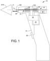
- Fig. 1 is a schematic view showing a rebound tonometer 10 formed in accordance with an embodiment of the present invention.
- Rebound tonometer 10 generally comprises a disposable probe 12 and a hand-held housing 14 containing a measurement system 16 configured to propel probe 12 in a forward direction along a measurement axis 11 toward an eye of test subject, wherein probe 12 contacts a cornea C of the eye and is rebounded from the cornea in a reverse direction opposite the forward direction.
- Probe 12 may include an elongated shaft 12A, at least a portion of which is made of a magnetic material, and a rounded tip 12B at an end of shaft 12A for contacting cornea C.
- Measurement system 16 may include a conductive drive coil 18 in which probe 12 is received, and a controller 20 configured to momentarily energize drive coil 18 to propel probe 12 forward toward the eye by electromagnetic force.
- Measurement system 16 may include a conductive measurement coil 22 through which probe 12 moves, and controller 20 may be further configured to measure a current induced in measurement coil 22 by the moving probe 12 and provide a measurement signal representing velocity of the probe as a function of time.
- controller 20 may be configured to receive the current induced in measurement coil 22 by the moving probe 12 and provide an analog voltage signal as the measurement signal.
- the embodiment depicted in Fig. 1 shows drive coil 18 and measurement coil 22 as being two different conductive coils. Alternatively, a single coil may act sequentially during a measurement cycle as both the drive coil and the measurement coil, thus eliminating the need for
- instrument 10 may further comprise an opto-electronic alignment detection system (not shown) and a display (not shown) to guide and confirm alignment of a measurement axis 11 of instrument 10 with cornea C and positioning of a front nose 28 of instrument 10 at a predetermined working distance from cornea C.
- a trigger button 26 may be provided on housing 14 for enabling a user to send a signal to controller 20 to initiate a measurement, and/or the alignment detection system may automatically send a signal to controller 20 to initiate a measurement when alignment and proper working distance are confirmed by the alignment detection system.
- Measurement system 16 further includes a signal processor 24, which may be part of controller 20 as shown in Fig. 1 .
- Signal processor 24 may be configured to convert the analog measurement signal to digital form, and to calculate a basic IOP measurement value from the digitized measurement signal.
- signal processor logic 20 may comprise an analog-to-digital signal converter and a programmed microprocessor for executing instructions stored in memory for calculating the basic IOP measurement value.
- Fig. 2 is a side view illustrating proper alignment of rebound tonometer 10 with an eye of a test subject, wherein measurement axis 11 of rebound tonometer 10 is horizontal.
- gravity force "g” acts perpendicular to the direction of motion of the tonometer's rebound probe 12 along measurement axis 11. Consequently, gravity force "g” does not have any component acting in the direction of motion of probe 12 that may influence the velocity at which the probe impacts the cornea and thereby affect the measurement result.
- Fig. 3 is another side view which also illustrates proper alignment of a rebound tonometer 10 with an eye of a test subject.
- the test subject's gaze direction is tilted slightly upward such that proper alignment requires that measurement axis 11 also be tilted from horizontal.
- gravity force "g" includes a component acting in the direction of motion of the probe.
- the gravity component will accelerate the probe as it travels toward the eye, causing the probe to impact the eye at a velocity greater than a desired predetermined velocity.
- the probe will be decelerated by gravity as it travels toward the eye.
- rebound tonometer 10 may be equipped with a tilt sensor 40 as shown in Fig. 1 .
- Tilt sensor 40 may be integrated in controller 20 or may be separate from controller 20 as depicted in Fig. 1 .
- Tilt sensor 40 generates a tilt signal indicating a direction (i.e. upward or downward) and degree of tilt of measurement axis 11 at the time a measurement is initiated.
- Tilt sensor 40 may be connected to signal processor 24 for processing the measurement signal representing motion of probe 12 to determine IOP.
- the tilt signal from tilt sensor 40 may be provided to signal processor 24 and taken into account in the calculation of IOP to compensate for the unwanted effects of gravity on the measurement.
- tilt sensor 40 may be embodied as a Bosch Sensortec BMA253 triaxial, low-g acceleration sensor with digital output.
- Fig. 4 is a flow diagram illustrating an example of logic followed by signal processor 24 of rebound tonometer 10 to compensate for effects of gravity due to tilting.
- the logic may be embodied by software code stored in memory in rebound tonometer 10 and executed by signal processor 24.
- tilt sensor 40 is monitored during an IOP measurement and the tilt angle of measurement axis 11 and probe 12 at the time of measurement is stored in memory.
- the IOP measurement is also taken and stored in memory pursuant to block 112. Flow may then branch to one of three flow paths depending upon the sensed tilt angle. If the tilt angle is zero or nearly zero in accordance with block 114, then the measured IOP is calculated without applying a tilt correction factor and is displayed as indicated by block 116.
- the IOP is calculated and adjusted by applying a tilt correction factor based on the sensed tilt angle to provide a final IOP measurement result, which is displayed as indicated by block 120.
- the tilt correction factor may be empirically determined in a calibration step by operating tonometer 10 at predetermined tilt angles using a simulated eye of known pressure, and a look-up table of applicable correction factors for various tilt angles may be stored in memory for use in block 120. Instead of a look-up table, a tilt correction function may be stored in memory for enabling calculation of an appropriate tilt correction factor based on the tilt signal.
- tilt correction factor may simply be addition of the tilt correction factor, which may be positive or negative, to the basic IOP measurement value. If the tilt angle is outside the acceptable range, for example its absolute value is greater than 30 degrees in accordance with block 122, then an error message is displayed such as "Excessive Tilt - Retry" as indicated in block 124.
Landscapes
- Health & Medical Sciences (AREA)
- Life Sciences & Earth Sciences (AREA)
- Engineering & Computer Science (AREA)
- Medical Informatics (AREA)
- Surgery (AREA)
- Biophysics (AREA)
- Biomedical Technology (AREA)
- Heart & Thoracic Surgery (AREA)
- Physics & Mathematics (AREA)
- Molecular Biology (AREA)
- Ophthalmology & Optometry (AREA)
- Animal Behavior & Ethology (AREA)
- General Health & Medical Sciences (AREA)
- Public Health (AREA)
- Veterinary Medicine (AREA)
- Signal Processing (AREA)
- Eye Examination Apparatus (AREA)
Description
- The present invention relates to rebound tonometers for measuring intraocular pressure (IOP).
- A rebound tonometer is a hand-held instrument that propels a movable measurement probe in a controlled manner toward the cornea of an eye to measure intraocular pressure and/or corneal biomechanics. The measurement probe is a disposable item typically having an elongated shaft terminating in a rounded tip. A new sterile measurement probe is loaded in the rebound tonometer prior to taking measurements on a patient. During a measurement, the probe contacts the cornea, is decelerated at a rate which depends on intraocular pressure, and then rebounds in a direction away from the cornea back toward the instrument housing. The rebound tonometer detects the motion of the measurement probe and determines intraocular pressure based on the detected motion of the probe. For example, the measurement probe may have a magnetized shaft which travels within a coil in the instrument housing. The coil may be energized momentarily to propel the probe toward the cornea by electromagnetic force, and then, after energizing current to the coil is shut off, a current may be induced in the coil by the moving probe to provide a detectable voltage signal (a measurement signal) representing motion of the probe. After measurements have been taken on a patient, the used measurement probe is discarded.
- The measurement accuracy of a rebound tonometer is dependent upon alignment of the instrument with the eye. Theoretically, for greatest accuracy, a travel axis of the probe (the measurement axis) should coincide with a central optical axis of the eye and the probe should travel a predetermined working distance along the measurement axis before contacting the eye at or very close to the corneal apex. To help with alignment and stability, it is known to provide an adjustable forehead support above the probe mechanism. The forehead support protrudes from the tonometer housing, and a distal end of the forehead support may be placed against the patient's forehead to establish a proper working distance. It is also known to equip a rebound tonometer with a sensing system capable of evaluating alignment and providing a yes or no indication of alignment to the user. Nevertheless, considerable skill and time is required to properly align the measurement axis to the eye. Because several (e.g. six) measurements may be recommended per eye and extra readings are often needed to refine alignment, rebound tonometry is sometimes considered inefficient.
- The position of the patient's head and direction of the patient's gaze may complicate alignment. If the patient's head is tilted and/or the patient's gaze is fixated along a direction that is inclined relative to horizontal, then the measurement axis cannot be properly aligned with the eye without tilting the rebound tonometer so the measurement axis is also inclined. However, if the measurement axis along which the probe travels is tilted to have a vertical component, the effects of gravity on the probe's motion may decrease measurement accuracy.
U.S. Patent Application Publication No. 2016/0174838 teaches a rebound tonometer in which a tilt sensor (i.e. an inclinometer) is used to alert the operator prior to measurement that the measurement axis is inclined so that the operator may eliminate the inclination by repositioning the rebound tonometer and/or the patient so that the measurement axis is horizontal. However, if a measurement is made while the measurement axis is tilted, the accuracy of the measurement suffers due to the mentioned gravitational effects. -
DE 10 2004 001675 A1 relates to a method for measuring the intraocular pressure (IOP) of an elastic test body with a tonometer by accelerating a small measuring body from a short distance from a rest position along a predetermined path in the direction of the test body. The measurement body impacts the test body and then rebounds in the direction of the rest position.DE 10 2004 001675 A1 mentions the use of an angle sensor that is said to be able to help correct for the influence of the angle of the device, which has an effect of the motion of the measuring body. - A rebound tonometer is claimed, having a hand-held body, a measurement axis, a probe, a display, means for propelling the probe along the measurement axis toward an eye of a test subject such that the probe contacts and rebounds from the eye, means for generating a measurement signal representing motion of the probe, a signal processor configured to calculate a basic IOP measurement value based on the measurement signal, and a tilt sensor for detecting tilt of the measurement axis relative to horizontal: the tilt sensor being configured to generate a tilt signal indicating a direction and a degree of tilt of the measurement axis relative to horizontal when the probe is propelled toward the eye, wherein the tilt sensor is connected to the signal processor and the tilt signal is provided to the signal processor; and the signal processor being configured to apply a tilt correction factor to the basic IOP measurement value to provide a final IOP measurement value, wherein the tilt correction factor depends on the direction and the degree of tilt indicated by the tilt signal; wherein the signal processor is configured to: apply the tilt correction factor when the degree of tilt indicated by the tilt signal is within a predetermined range, and generate an error message when the degree of tilt indicated by the tilt signal is outside the predetermined range.
- A rebound tonometry method according to the present disclosure generally comprises the steps of operating a rebound tonometer to propel a measurement probe along a measurement axis toward an eye of a test subject such that the measurement probe is rebounded by the eye in a direction away from the eye, detecting measurement data describing motion of the measurement probe toward and away from the eye, sensing a direction and a degree of tilt of the measurement axis when the measurement probe is propelled toward the eye, calculating a basic IOP measurement value from the measurement data, and applying a tilt correction factor to the basic IOP measurement value to yield a final IOP measurement value, wherein the tilt correction factor depends on the direction and the degree of tilt and apply the tilt correction factor when the degree of tilt indicated by the tilt signal is within a predetermined range, and display an error message when the degree of tilt indicated by the tilt signal is outside the predetermined range.
- The present disclosure also provides a non-claimed method of calibrating a rebound tonometer generally comprising the steps of operating the rebound tonometer at predetermined tilt angles of the measurement axis to measure pressure of a simulated eye having a known pressure to determine a difference between the measured pressure and the known pressure, and storing information for determining an applicable tilt correction factor corresponding to each of the predetermined tilt angles, wherein application of the applicable tilt correction factor to the measured pressure at the corresponding predetermined tilt angle yields the known pressure, and wherein the stored information is available during normal use of the calibrated rebound tonometer.
- The nature and mode of operation of the present invention will now be more fully described in the following detailed description of the invention taken with the accompanying drawing figures, in which:
-
Fig. 1 is a schematic view of a rebound tonometer having tilt correction in accordance with an embodiment of the present invention -
Fig. 2 is a side view illustrating proper alignment of a rebound tonometer with an eye of a test subject, wherein a measurement axis of the rebound tonometer is horizontal; -
Fig. 3 is another side view also illustrating proper alignment of a rebound tonometer with an eye of a test subject, but the measurement axis is tilted from horizontal; and -
Fig. 4 is a flow diagram illustrating logic used by the rebound tonometer of Fig. 11 to compensate for effects of gravity due to tilting. - The present disclosure relates to improving a rebound tonometer by incorporating a tilt sensor to compensate for gravity effects when a measurement axis of a rebound tonometer is tilted from horizontal during a measurement.
-
Fig. 1 is a schematic view showing arebound tonometer 10 formed in accordance with an embodiment of the present invention.Rebound tonometer 10 generally comprises adisposable probe 12 and a hand-heldhousing 14 containing ameasurement system 16 configured topropel probe 12 in a forward direction along ameasurement axis 11 toward an eye of test subject, whereinprobe 12 contacts a cornea C of the eye and is rebounded from the cornea in a reverse direction opposite the forward direction. -
Probe 12 may include anelongated shaft 12A, at least a portion of which is made of a magnetic material, and arounded tip 12B at an end ofshaft 12A for contacting corneaC. Measurement system 16 may include aconductive drive coil 18 in whichprobe 12 is received, and a controller 20 configured to momentarily energizedrive coil 18 to propelprobe 12 forward toward the eye by electromagnetic force.Measurement system 16 may include aconductive measurement coil 22 through whichprobe 12 moves, and controller 20 may be further configured to measure a current induced inmeasurement coil 22 by the movingprobe 12 and provide a measurement signal representing velocity of the probe as a function of time. For example, controller 20 may be configured to receive the current induced inmeasurement coil 22 by the movingprobe 12 and provide an analog voltage signal as the measurement signal. The embodiment depicted inFig. 1 showsdrive coil 18 andmeasurement coil 22 as being two different conductive coils. Alternatively, a single coil may act sequentially during a measurement cycle as both the drive coil and the measurement coil, thus eliminating the need for a second coil. - As known in the art of rebound tonometers,
instrument 10 may further comprise an opto-electronic alignment detection system (not shown) and a display (not shown) to guide and confirm alignment of ameasurement axis 11 ofinstrument 10 with cornea C and positioning of afront nose 28 ofinstrument 10 at a predetermined working distance from cornea C. Atrigger button 26 may be provided onhousing 14 for enabling a user to send a signal to controller 20 to initiate a measurement, and/or the alignment detection system may automatically send a signal to controller 20 to initiate a measurement when alignment and proper working distance are confirmed by the alignment detection system. -
Measurement system 16 further includes asignal processor 24, which may be part of controller 20 as shown inFig. 1 .Signal processor 24 may be configured to convert the analog measurement signal to digital form, and to calculate a basic IOP measurement value from the digitized measurement signal. For example, signal processor logic 20 may comprise an analog-to-digital signal converter and a programmed microprocessor for executing instructions stored in memory for calculating the basic IOP measurement value. - Reference is now made to
Figs. 2 and 3. Fig. 2 is a side view illustrating proper alignment ofrebound tonometer 10 with an eye of a test subject, whereinmeasurement axis 11 ofrebound tonometer 10 is horizontal. As may be seen, gravity force "g" acts perpendicular to the direction of motion of the tonometer'srebound probe 12 alongmeasurement axis 11. Consequently, gravity force "g" does not have any component acting in the direction of motion ofprobe 12 that may influence the velocity at which the probe impacts the cornea and thereby affect the measurement result. -
Fig. 3 is another side view which also illustrates proper alignment of arebound tonometer 10 with an eye of a test subject. However, inFig. 3 , the test subject's gaze direction is tilted slightly upward such that proper alignment requires thatmeasurement axis 11 also be tilted from horizontal. In this situation, gravity force "g" includes a component acting in the direction of motion of the probe. As may be understood fromFig. 3 , the gravity component will accelerate the probe as it travels toward the eye, causing the probe to impact the eye at a velocity greater than a desired predetermined velocity. Of course, if the test subject's gaze direction is tilted downward rather than upward, the probe will be decelerated by gravity as it travels toward the eye. - In order to compensate for effects of gravity where
measurement axis 11 is tilted from horizontal,rebound tonometer 10 may be equipped with atilt sensor 40 as shown inFig. 1 .Tilt sensor 40 may be integrated in controller 20 or may be separate from controller 20 as depicted inFig. 1 .Tilt sensor 40 generates a tilt signal indicating a direction (i.e. upward or downward) and degree of tilt ofmeasurement axis 11 at the time a measurement is initiated.Tilt sensor 40 may be connected tosignal processor 24 for processing the measurement signal representing motion ofprobe 12 to determine IOP. The tilt signal fromtilt sensor 40 may be provided to signalprocessor 24 and taken into account in the calculation of IOP to compensate for the unwanted effects of gravity on the measurement. By way of non-limiting example,tilt sensor 40 may be embodied as a Bosch Sensortec BMA253 triaxial, low-g acceleration sensor with digital output. -
Fig. 4 is a flow diagram illustrating an example of logic followed bysignal processor 24 ofrebound tonometer 10 to compensate for effects of gravity due to tilting. The logic may be embodied by software code stored in memory inrebound tonometer 10 and executed bysignal processor 24. As shown in block 110,tilt sensor 40 is monitored during an IOP measurement and the tilt angle ofmeasurement axis 11 and probe 12 at the time of measurement is stored in memory. The IOP measurement is also taken and stored in memory pursuant to block 112. Flow may then branch to one of three flow paths depending upon the sensed tilt angle. If the tilt angle is zero or nearly zero in accordance withblock 114, then the measured IOP is calculated without applying a tilt correction factor and is displayed as indicated byblock 116. If the tilt angle is between zero degrees and relatively low tilt angle, for example ±30 degrees in accordance withblock 118, then the IOP is calculated and adjusted by applying a tilt correction factor based on the sensed tilt angle to provide a final IOP measurement result, which is displayed as indicated byblock 120. The tilt correction factor may be empirically determined in a calibration step by operatingtonometer 10 at predetermined tilt angles using a simulated eye of known pressure, and a look-up table of applicable correction factors for various tilt angles may be stored in memory for use inblock 120. Instead of a look-up table, a tilt correction function may be stored in memory for enabling calculation of an appropriate tilt correction factor based on the tilt signal. Application of the tilt correction factor may simply be addition of the tilt correction factor, which may be positive or negative, to the basic IOP measurement value. If the tilt angle is outside the acceptable range, for example its absolute value is greater than 30 degrees in accordance withblock 122, then an error message is displayed such as "Excessive Tilt - Retry" as indicated inblock 124.
Claims (7)
- A rebound tonometer (10) having a hand-held body (14), a measurement axis (11), a probe (12), a display, means for propelling the probe along the measurement axis toward an eye of a test subject such that the probe (12) contacts and rebounds from the eye (C), means for generating a measurement signal representing motion of the probe, a signal processor (24) configured to calculate a basic IOP measurement value based on the measurement signal, and a tilt sensor (40) for detecting tilt of the measurement axis relative to horizontal:the tilt sensor (40) being configured to generate a tilt signal indicating a direction and a degree of tilt of the measurement axis (11) relative to horizontal when the probe is propelled toward the eye (C), wherein the tilt sensor (40) is connected to the signal processor (24) and the tilt signal is provided to the signal processor (24); andthe signal processor (24) being configured to apply a tilt correction factor to the basic IOP measurement value to provide a final IOP measurement value, wherein the tilt correction factor depends on the direction and the degree of tilt indicated by the tilt signal;wherein the signal processor (24) is configured to: apply the tilt correction factor when the degree of tilt indicated by the tilt signal is within a predetermined range, and display an error message on the display when the degree of tilt indicated by the tilt signal is outside the predetermined range.
- The rebound tonometer (10) according to claim 1, comprising of a memory connected to the signal processor (24), wherein the tilt correction factor is stored in the memory.
- The rebound tonometer (10) according to claim 2, wherein the tilt correction factor is empirically determined during calibration of the rebound tonometer (10).
- The rebound tonometer according to any one of claims 1 to 3, wherein the means for propelling the probe includes a conductive coil (18) energizable to propel the probe along the measurement axis (11) toward an eye (C) of a test subject.
- The rebound tonometer according to any one of claims 1 to 4, wherein the means for generating the measurement signal includes a conductive coil (22) through which the probe (12) moves and induces current.
- The rebound tonometer according to any one of claims 1 to 5, wherein the means for propelling the probe (12) and the means for generating the measurement signal together include only a single conductive coil, wherein the single conductive coil is energizable to propel the probe (12), and movement of the probe (12) through the single conductive coil induces current to generate the measurement signal.
- A rebound tonometry method comprising the steps of:
operating a rebound tonometer (10) according to any of claims 1-6 to propel a measurement probe (12) along a measurement axis (11) toward an eye (C) of a test subject, wherein the measurement probe (12) is rebounded by the eye (C) in a direction away from the eye;detecting measurement data describing motion of the measurement probe (12) toward and away from the eye (C);sensing a direction and a degree of tilt of the measurement axis (11) when the measurement probe (12) is propelled toward the eye (C);calculating a basic IOP measurement value from the measurement data; and applying a tilt correction factor to the basic IOP measurement value to yield a final IOP measurement value, wherein the tilt correction factor depends on the direction and the degree of tilt;wherein the tilt correction factor is applied when the degree of tilt indicated by the tilt signal is within a predetermined range, and an error message is displayed when the degree of tilt indicated by the tilt signal is outside the predetermined range.
Applications Claiming Priority (2)
| Application Number | Priority Date | Filing Date | Title |
|---|---|---|---|
| US201762557553P | 2017-09-12 | 2017-09-12 | |
| PCT/US2018/050346 WO2019055374A1 (en) | 2017-09-12 | 2018-09-11 | Rebound tonometer having tilt correction |
Publications (4)
| Publication Number | Publication Date |
|---|---|
| EP3681374A1 EP3681374A1 (en) | 2020-07-22 |
| EP3681374A4 EP3681374A4 (en) | 2021-07-07 |
| EP3681374C0 EP3681374C0 (en) | 2025-02-12 |
| EP3681374B1 true EP3681374B1 (en) | 2025-02-12 |
Family
ID=65724086
Family Applications (1)
| Application Number | Title | Priority Date | Filing Date |
|---|---|---|---|
| EP18855934.8A Active EP3681374B1 (en) | 2017-09-12 | 2018-09-11 | Rebound tonometer having tilt correction |
Country Status (3)
| Country | Link |
|---|---|
| US (2) | US11717162B2 (en) |
| EP (1) | EP3681374B1 (en) |
| WO (1) | WO2019055374A1 (en) |
Families Citing this family (8)
| Publication number | Priority date | Publication date | Assignee | Title |
|---|---|---|---|---|
| US11957413B2 (en) * | 2019-08-06 | 2024-04-16 | University of Pittsburgh—of the Commonwealth System of Higher Education | Solitary wave-based trans-lid tonometer |
| JP7672733B2 (en) * | 2021-03-29 | 2025-05-08 | 国立大学法人東北大学 | Hardness calculation device, hardness measurement device, and method of operating the hardness calculation device |
| FI130061B (en) * | 2021-10-21 | 2023-01-13 | Icare Finland Oy | Rebound tonometers and procedures for using rebound tonometers |
| DE102022201296A1 (en) | 2022-02-08 | 2023-08-10 | Carl Zeiss Meditec Ag | Arrangement for obtaining diagnostic information from the eye |
| CN116869474A (en) * | 2023-07-20 | 2023-10-13 | 海思视康(上海)生物医学科技有限公司 | intraocular pressure measuring device |
| US12419518B2 (en) | 2023-08-16 | 2025-09-23 | Reichert, Inc. | Ophthalmic instrument probe detection method |
| US20260026689A1 (en) * | 2024-07-25 | 2026-01-29 | Reichert, Inc. | Self-measurement ophthalmic instrument |
| CN119498770B (en) * | 2024-09-29 | 2025-10-14 | 海思视康(上海)生物医学科技有限公司 | Rebound tonometer and intraocular pressure measurement method |
Citations (2)
| Publication number | Priority date | Publication date | Assignee | Title |
|---|---|---|---|---|
| DE102004001675A1 (en) | 2004-01-12 | 2005-08-04 | Emil Hohl | Internal pressure measurement method for elastic test body, especially for measuring intra-ocular pressure, uses tonometer and comprises initially carrying out reference measurement to determine calibration parameters |
| WO2014202840A1 (en) | 2013-06-20 | 2014-12-24 | Icare Finland Oy | An optometric instrument with alignment means and method for aligning an optometric instrument |
Family Cites Families (9)
| Publication number | Priority date | Publication date | Assignee | Title |
|---|---|---|---|---|
| US6440070B2 (en) * | 2000-05-08 | 2002-08-27 | Ness Tec Ophthalmic Systems Ltd. | Intraocular pressure measurement |
| US7204806B2 (en) | 2003-06-17 | 2007-04-17 | Mitsugu Shimmyo | Method and apparatus for obtaining corrected intraocular pressure values |
| US8915253B2 (en) | 2005-07-18 | 2014-12-23 | Tearscience, Inc. | Method and apparatus for treating gland dysfunction employing heated medium |
| CN101190122B (en) * | 2006-11-30 | 2012-01-11 | 蒂奥拉特公司 | Method for measuring intraocular pressure |
| US9232892B2 (en) * | 2010-11-03 | 2016-01-12 | Lighttouch, Llc | Applanation tonometer and method for measuring the intraocular pressure of the eye |
| US8862420B2 (en) | 2013-02-05 | 2014-10-14 | Reno Sub-Sustems Canada Incorporated | Multi-axis tilt sensor for correcting gravitational effects on the measurement of pressure by a capacitance diaphragm gauge |
| CN104274153B (en) * | 2014-10-30 | 2016-02-10 | 武汉创博达信息科技有限公司 | A kind of soft-touch type intraocular pressure level or vertical survey device and method |
| MX2018002494A (en) * | 2015-08-27 | 2018-11-29 | Equinox Ophthalmic Inc | IDENTIFICATION AND MODIFICATION OF INTRACORPORAL PRESSURE RELATED TO EYES. |
| FI127018B (en) * | 2015-12-18 | 2017-09-29 | Icare Finland Oy | APPARATUS FOR MEASUREMENT OF EYE PRESSURE |
-
2018
- 2018-09-11 WO PCT/US2018/050346 patent/WO2019055374A1/en not_active Ceased
- 2018-09-11 US US16/645,523 patent/US11717162B2/en active Active
- 2018-09-11 EP EP18855934.8A patent/EP3681374B1/en active Active
-
2023
- 2023-06-19 US US18/211,364 patent/US12396644B2/en active Active
Patent Citations (3)
| Publication number | Priority date | Publication date | Assignee | Title |
|---|---|---|---|---|
| DE102004001675A1 (en) | 2004-01-12 | 2005-08-04 | Emil Hohl | Internal pressure measurement method for elastic test body, especially for measuring intra-ocular pressure, uses tonometer and comprises initially carrying out reference measurement to determine calibration parameters |
| DE102004001675B4 (en) * | 2004-01-12 | 2009-01-29 | Emil Hohl | Method and device for measuring the internal pressure of an elastic specimen, in particular for measuring intraocular pressure |
| WO2014202840A1 (en) | 2013-06-20 | 2014-12-24 | Icare Finland Oy | An optometric instrument with alignment means and method for aligning an optometric instrument |
Non-Patent Citations (1)
| Title |
|---|
| ANONYMOUS: "icare tonometer ONE - USER'S AND MAINTENANCE MANUAL (v1.11)", ICARE ONE, 1 June 2013 (2013-06-01), XP093337997 |
Also Published As
| Publication number | Publication date |
|---|---|
| US20200196864A1 (en) | 2020-06-25 |
| WO2019055374A1 (en) | 2019-03-21 |
| EP3681374A1 (en) | 2020-07-22 |
| EP3681374C0 (en) | 2025-02-12 |
| US12396644B2 (en) | 2025-08-26 |
| US11717162B2 (en) | 2023-08-08 |
| US20230329552A1 (en) | 2023-10-19 |
| EP3681374A4 (en) | 2021-07-07 |
Similar Documents
| Publication | Publication Date | Title |
|---|---|---|
| US12396644B2 (en) | Rebound tonometer having tilt correction | |
| CN110584595B (en) | Rebound intraocular pressure measuring method and device | |
| EP3389470B1 (en) | Apparatus for measuring intraocular pressure | |
| EP4418984B1 (en) | Rebound tonometers and methods for using rebound tonometers | |
| KR102472465B1 (en) | Oscillation measuring device and its control method for implant | |
| EP4096496A1 (en) | Positioning system for ophthalmic instrument | |
| FI113450B (en) | Apparatus for measuring eye pressure | |
| KR20220115371A (en) | Implant-vibration measuring instrument and method | |
| FI131113B1 (en) | Device and method for measuring properties of a target | |
| KR101060063B1 (en) | Detachable putting guide device using the weight of inertia |
Legal Events
| Date | Code | Title | Description |
|---|---|---|---|
| STAA | Information on the status of an ep patent application or granted ep patent |
Free format text: STATUS: THE INTERNATIONAL PUBLICATION HAS BEEN MADE |
|
| PUAI | Public reference made under article 153(3) epc to a published international application that has entered the european phase |
Free format text: ORIGINAL CODE: 0009012 |
|
| STAA | Information on the status of an ep patent application or granted ep patent |
Free format text: STATUS: REQUEST FOR EXAMINATION WAS MADE |
|
| 17P | Request for examination filed |
Effective date: 20200319 |
|
| AK | Designated contracting states |
Kind code of ref document: A1 Designated state(s): AL AT BE BG CH CY CZ DE DK EE ES FI FR GB GR HR HU IE IS IT LI LT LU LV MC MK MT NL NO PL PT RO RS SE SI SK SM TR |
|
| AX | Request for extension of the european patent |
Extension state: BA ME |
|
| DAV | Request for validation of the european patent (deleted) | ||
| DAX | Request for extension of the european patent (deleted) | ||
| A4 | Supplementary search report drawn up and despatched |
Effective date: 20210608 |
|
| RIC1 | Information provided on ipc code assigned before grant |
Ipc: A61B 3/16 20060101AFI20210601BHEP |
|
| P01 | Opt-out of the competence of the unified patent court (upc) registered |
Effective date: 20230525 |
|
| GRAP | Despatch of communication of intention to grant a patent |
Free format text: ORIGINAL CODE: EPIDOSNIGR1 |
|
| GRAP | Despatch of communication of intention to grant a patent |
Free format text: ORIGINAL CODE: EPIDOSNIGR1 |
|
| STAA | Information on the status of an ep patent application or granted ep patent |
Free format text: STATUS: GRANT OF PATENT IS INTENDED |
|
| INTG | Intention to grant announced |
Effective date: 20240614 |
|
| GRAJ | Information related to disapproval of communication of intention to grant by the applicant or resumption of examination proceedings by the epo deleted |
Free format text: ORIGINAL CODE: EPIDOSDIGR1 |
|
| STAA | Information on the status of an ep patent application or granted ep patent |
Free format text: STATUS: REQUEST FOR EXAMINATION WAS MADE |
|
| INTC | Intention to grant announced (deleted) | ||
| RAP3 | Party data changed (applicant data changed or rights of an application transferred) |
Owner name: REICHERT, INC. |
|
| GRAP | Despatch of communication of intention to grant a patent |
Free format text: ORIGINAL CODE: EPIDOSNIGR1 |
|
| STAA | Information on the status of an ep patent application or granted ep patent |
Free format text: STATUS: GRANT OF PATENT IS INTENDED |
|
| INTG | Intention to grant announced |
Effective date: 20241008 |
|
| GRAS | Grant fee paid |
Free format text: ORIGINAL CODE: EPIDOSNIGR3 |
|
| GRAA | (expected) grant |
Free format text: ORIGINAL CODE: 0009210 |
|
| STAA | Information on the status of an ep patent application or granted ep patent |
Free format text: STATUS: THE PATENT HAS BEEN GRANTED |
|
| AK | Designated contracting states |
Kind code of ref document: B1 Designated state(s): AL AT BE BG CH CY CZ DE DK EE ES FI FR GB GR HR HU IE IS IT LI LT LU LV MC MK MT NL NO PL PT RO RS SE SI SK SM TR |
|
| REG | Reference to a national code |
Ref country code: GB Ref legal event code: FG4D |
|
| REG | Reference to a national code |
Ref country code: CH Ref legal event code: EP |
|
| REG | Reference to a national code |
Ref country code: DE Ref legal event code: R096 Ref document number: 602018079156 Country of ref document: DE |
|
| REG | Reference to a national code |
Ref country code: IE Ref legal event code: FG4D |
|
| U01 | Request for unitary effect filed |
Effective date: 20250225 |
|
| U07 | Unitary effect registered |
Designated state(s): AT BE BG DE DK EE FI FR IT LT LU LV MT NL PT RO SE SI Effective date: 20250303 |
|
| P04 | Withdrawal of opt-out of the competence of the unified patent court (upc) registered |
Free format text: CASE NUMBER: APP_9734/2025 Effective date: 20250226 |
|
| PG25 | Lapsed in a contracting state [announced via postgrant information from national office to epo] |
Ref country code: RS Free format text: LAPSE BECAUSE OF FAILURE TO SUBMIT A TRANSLATION OF THE DESCRIPTION OR TO PAY THE FEE WITHIN THE PRESCRIBED TIME-LIMIT Effective date: 20250512 |
|
| PG25 | Lapsed in a contracting state [announced via postgrant information from national office to epo] |
Ref country code: PL Free format text: LAPSE BECAUSE OF FAILURE TO SUBMIT A TRANSLATION OF THE DESCRIPTION OR TO PAY THE FEE WITHIN THE PRESCRIBED TIME-LIMIT Effective date: 20250212 |
|
| PG25 | Lapsed in a contracting state [announced via postgrant information from national office to epo] |
Ref country code: ES Free format text: LAPSE BECAUSE OF FAILURE TO SUBMIT A TRANSLATION OF THE DESCRIPTION OR TO PAY THE FEE WITHIN THE PRESCRIBED TIME-LIMIT Effective date: 20250212 |
|
| PG25 | Lapsed in a contracting state [announced via postgrant information from national office to epo] |
Ref country code: IS Free format text: LAPSE BECAUSE OF FAILURE TO SUBMIT A TRANSLATION OF THE DESCRIPTION OR TO PAY THE FEE WITHIN THE PRESCRIBED TIME-LIMIT Effective date: 20250612 Ref country code: NO Free format text: LAPSE BECAUSE OF FAILURE TO SUBMIT A TRANSLATION OF THE DESCRIPTION OR TO PAY THE FEE WITHIN THE PRESCRIBED TIME-LIMIT Effective date: 20250512 |
|
| PG25 | Lapsed in a contracting state [announced via postgrant information from national office to epo] |
Ref country code: HR Free format text: LAPSE BECAUSE OF FAILURE TO SUBMIT A TRANSLATION OF THE DESCRIPTION OR TO PAY THE FEE WITHIN THE PRESCRIBED TIME-LIMIT Effective date: 20250212 |
|
| PG25 | Lapsed in a contracting state [announced via postgrant information from national office to epo] |
Ref country code: GR Free format text: LAPSE BECAUSE OF FAILURE TO SUBMIT A TRANSLATION OF THE DESCRIPTION OR TO PAY THE FEE WITHIN THE PRESCRIBED TIME-LIMIT Effective date: 20250513 |
|
| PG25 | Lapsed in a contracting state [announced via postgrant information from national office to epo] |
Ref country code: SM Free format text: LAPSE BECAUSE OF FAILURE TO SUBMIT A TRANSLATION OF THE DESCRIPTION OR TO PAY THE FEE WITHIN THE PRESCRIBED TIME-LIMIT Effective date: 20250212 |
|
| PGFP | Annual fee paid to national office [announced via postgrant information from national office to epo] |
Ref country code: GB Payment date: 20250919 Year of fee payment: 8 |
|
| PG25 | Lapsed in a contracting state [announced via postgrant information from national office to epo] |
Ref country code: CZ Free format text: LAPSE BECAUSE OF FAILURE TO SUBMIT A TRANSLATION OF THE DESCRIPTION OR TO PAY THE FEE WITHIN THE PRESCRIBED TIME-LIMIT Effective date: 20250212 |
|
| U1N | Appointed representative for the unitary patent procedure changed after the registration of the unitary effect |
Representative=s name: FOUNTAIN, SULLIVAN; GB |
|
| PG25 | Lapsed in a contracting state [announced via postgrant information from national office to epo] |
Ref country code: SK Free format text: LAPSE BECAUSE OF FAILURE TO SUBMIT A TRANSLATION OF THE DESCRIPTION OR TO PAY THE FEE WITHIN THE PRESCRIBED TIME-LIMIT Effective date: 20250212 |
|
| U20 | Renewal fee for the european patent with unitary effect paid |
Year of fee payment: 8 Effective date: 20250924 |
|
| PLBI | Opposition filed |
Free format text: ORIGINAL CODE: 0009260 |
|
| PLAX | Notice of opposition and request to file observation + time limit sent |
Free format text: ORIGINAL CODE: EPIDOSNOBS2 |
|
| 26 | Opposition filed |
Opponent name: ICARE FINLAND OY Effective date: 20251112 |