EP3681104A1 - Optimisation method - Google Patents
Optimisation method Download PDFInfo
- Publication number
- EP3681104A1 EP3681104A1 EP19216956.3A EP19216956A EP3681104A1 EP 3681104 A1 EP3681104 A1 EP 3681104A1 EP 19216956 A EP19216956 A EP 19216956A EP 3681104 A1 EP3681104 A1 EP 3681104A1
- Authority
- EP
- European Patent Office
- Prior art keywords
- power system
- sub
- computer
- phase
- implemented method
- Prior art date
- Legal status (The legal status is an assumption and is not a legal conclusion. Google has not performed a legal analysis and makes no representation as to the accuracy of the status listed.)
- Granted
Links
Images

Classifications
-
- G—PHYSICS
- G06—COMPUTING OR CALCULATING; COUNTING
- G06F—ELECTRIC DIGITAL DATA PROCESSING
- G06F9/00—Arrangements for program control, e.g. control units
- G06F9/06—Arrangements for program control, e.g. control units using stored programs, i.e. using an internal store of processing equipment to receive or retain programs
- G06F9/44—Arrangements for executing specific programs
- G06F9/445—Program loading or initiating
- G06F9/44505—Configuring for program initiating, e.g. using registry, configuration files
- G06F9/4451—User profiles; Roaming
-
- H—ELECTRICITY
- H04—ELECTRIC COMMUNICATION TECHNIQUE
- H04L—TRANSMISSION OF DIGITAL INFORMATION, e.g. TELEGRAPHIC COMMUNICATION
- H04L41/00—Arrangements for maintenance, administration or management of data switching networks, e.g. of packet switching networks
- H04L41/08—Configuration management of networks or network elements
- H04L41/0803—Configuration setting
- H04L41/0823—Configuration setting characterised by the purposes of a change of settings, e.g. optimising configuration for enhancing reliability
-
- G—PHYSICS
- G08—SIGNALLING
- G08G—TRAFFIC CONTROL SYSTEMS
- G08G5/00—Traffic control systems for aircraft
- G08G5/30—Flight plan management
- G08G5/34—Flight plan management for flight plan modification
-
- G—PHYSICS
- G08—SIGNALLING
- G08G—TRAFFIC CONTROL SYSTEMS
- G08G5/00—Traffic control systems for aircraft
- G08G5/20—Arrangements for acquiring, generating, sharing or displaying traffic information
- G08G5/21—Arrangements for acquiring, generating, sharing or displaying traffic information located onboard the aircraft
-
- G—PHYSICS
- G08—SIGNALLING
- G08G—TRAFFIC CONTROL SYSTEMS
- G08G5/00—Traffic control systems for aircraft
- G08G5/20—Arrangements for acquiring, generating, sharing or displaying traffic information
- G08G5/26—Transmission of traffic-related information between aircraft and ground stations
-
- G—PHYSICS
- G08—SIGNALLING
- G08G—TRAFFIC CONTROL SYSTEMS
- G08G5/00—Traffic control systems for aircraft
- G08G5/30—Flight plan management
- G08G5/32—Flight plan management for flight plan preparation
-
- G—PHYSICS
- G08—SIGNALLING
- G08G—TRAFFIC CONTROL SYSTEMS
- G08G5/00—Traffic control systems for aircraft
- G08G5/50—Navigation or guidance aids
- G08G5/53—Navigation or guidance aids for cruising
-
- G—PHYSICS
- G08—SIGNALLING
- G08G—TRAFFIC CONTROL SYSTEMS
- G08G5/00—Traffic control systems for aircraft
- G08G5/50—Navigation or guidance aids
- G08G5/55—Navigation or guidance aids for a single aircraft
-
- H—ELECTRICITY
- H04—ELECTRIC COMMUNICATION TECHNIQUE
- H04L—TRANSMISSION OF DIGITAL INFORMATION, e.g. TELEGRAPHIC COMMUNICATION
- H04L41/00—Arrangements for maintenance, administration or management of data switching networks, e.g. of packet switching networks
- H04L41/08—Configuration management of networks or network elements
- H04L41/0803—Configuration setting
- H04L41/0823—Configuration setting characterised by the purposes of a change of settings, e.g. optimising configuration for enhancing reliability
- H04L41/0833—Configuration setting characterised by the purposes of a change of settings, e.g. optimising configuration for enhancing reliability for reduction of network energy consumption
Definitions
- the present disclosure relates to a computer-implemented method of optimizing the performance of a reconfigurable power system.
- Power system optimisation over a mission / operating profile is generally treated as a finite horizon optimisation problem.
- the optimal configuration of the power system can be determined.
- There is a proposal to solve this as a model predictive control solution Huang, Y. et al., 2017. Model predictive control power management strategies for HEVs: A review. Journal of Power Sources ).
- solving the problem over the whole mission, with a full set of decision variables at each time step is computationally challenging - particularly for non-linear systems. Similar problems can be confronted in relation to non-vehicular power systems, such as static power generators.
- a computer-implemented method of optimizing the performance of a reconfigurable power system comprising the steps of:
- this method provides an approach to solve complex, large-scale optimisation problems in a practical time frame.
- the coarse optimisation allows the sub-phases to be decoupled by fixing boundary conditions for the fine grained optimisation, thus allowing the fine grain optimisation to be solved more simply in independence of the other sub-phases.
- the optimisation may act to improve parameters such as: fuel consumption, power availability, power efficiency, and component health.
- the computer-implemented method may have any one or, to the extent that they are compatible, any combination of the following optional features.
- the reconfigurable power system can be a power system in a vehicle.
- the operating profile can then be a mission profile for the vehicle.
- the vehicle can be an aircraft, a ship, a train, an automobile etc.
- the mission profile can be appropriate to the type of vehicle. For example, a flight plan for an aircraft; a shipping route and schedule for a ship; a route, timetable, and railway network signalling information, speed limits, inclines, availability of overhead power lines etc. for a hybrid locomotive system; a route with different classes of environment for an automobile.
- the coarse optimisation routine may include the steps of: (a) estimating, for each sub-phase under consideration, a value of an output parameter to be optimised by varying control parameters of the power system; (b) ranking each sub-phase under consideration based on the estimated value, and determining a highest ranking sub-phase; (c) fixing those control parameters of the power system which allowed the power system to achieve the estimated value of the output parameter for the highest ranking sub-phase; (d) removing the highest ranking sub-phase from consideration; and (e) repeating steps (a) - (d) in order to fix control parameters of the power system in respect of sub-phases remaining under consideration.
- the output parameter to be optimised may be fuel consumption, power availability, power efficiency, component health, response time/speed of response, maintenance cost, through-life cost (including capital expenditure and/or operational expenditure), emissions and/or environmental concerns, and/or energy trading costs (for example, if the power system is for land-based generation).
- the control parameters may include an engine shut down status, an energy storage status, an energy generation status etc.
- a control parameter fixed for the highest ranking sub-phase may impose a constraint on a control parameter of one or more other sub-phases under consideration such that the value of the constrained control parameter may be fixed for those sub-phases. For example, if in one sub-phase a control parameter requires that a battery must be used to power one or more motors, previous sub-phases may be constrained to (i) not use the power stored in that battery; (ii) use the power stored in that battery but leave a predetermined amount of energy in the battery; and/or (iii) place the battery in a charging state.
- the constraints imposed on the sub-phases for the coarse optimisation routine may be imposed on the sub-phases for the fine optimisation routine.
- the computational complexity of the fine optimisation routine may be reduced as a result.
- the computer-implemented method may include a step, performed before partitioning the operating profile, of receiving a condition of the power system and determining, based on the operating profile and the condition of the power system, whether a goal of the operating profile can be achieved.
- the condition of the power system can be: fixed demands on the system, system resources, system restrictions, system health, expected power demands, change in resources (for example change in feasibility for planned engine shutdown, change in generator health and therefore advised operation regions) etc.
- Determining whether the goal of the operating profile can be achieved may include determining whether power available within the power system is sufficient to achieve the goal of the operating profile. If the determination is that the power available is insufficient, one or more power drains on the system may be disengaged based on predetermined priority levels of the power drains.
- Determining whether the goal of the operating profile can be achieved may include deriving an initial configuration of control parameters of the power system which allows the goal to be achieved, and this initial configuration may be the subject of the coarse optimisation routine.
- the coarse optimisation routine may use a set of heuristic optimisation rules.
- the coarse optimisation routine may use one or more greedy optimisation rules, which may consider a subset of control parameters by aggregating the control parameters.
- the use of a heuristic rule-based optimiser can ensure that the best configuration is set for each sub-phase, and can remove or reduce the need to iterate the process.
- the fine optimisation routine may use either a deterministic heuristic method; a stochastic heuristic method; or a hybrid thereof.
- Partitioning the operating profile may be based on any one or more of: a power demand tolerance; an environment allowance; an operation phase; component health information; an availability of one or more energy storage components; an environment in which a vehicle is to operate (e.g. significantly different altitudes, in which allowed noise and/or emissions levels may vary).
- example operation phases may be different phases of flight.
- example phases may be different times during the day as energy trading costs and/or loads may vary in time.
- a flight management computer which is configured to perform the computer-implemented method of the first aspect, the reconfigurable power system being a power system in an aircraft, and the operating profile being a mission profile for the aircraft.
- the flight management computer of the second aspect may have any one of, or indeed insofar as they are compatible any combination of, the optional features of the first aspect.
- an aircraft including the flight management computer of the second aspect.
- a method of operating a reconfigurable power system comprising the steps of: performing the computer-implemented method of the first aspect to optimize the performance of a reconfigurable power system; and operating the reconfigurable power system to perform the operating profile.
- the method of the fourth aspect may have any one of, or indeed insofar as they are compatible any combination of, the optional features of the first aspect.
- either or both of: an updated operating profile, or an updated condition of the reconfigurable power system, may be received, and the step of performing the computer-implemented method may be repeated using the received updated operating profile and/or updated condition of the reconfigurable power system.
- a computer program comprising code which, when run on a computer, causes the computer to perform the computer-implemented method of the first aspect
- a computer readable medium storing a computer program comprising code which, when run on a computer, causes the computer to perform the computer-implemented method of the first aspect
- a computer system programmed to perform the computer-implemented method of the first aspect.
- the disclosure herein describes an approach to solve complex, large-scale optimisation problems in a practicable and timely manner.
- the large-scale problem is decomposed into a set of interdependent optimisation sub-problems.
- Interdependent problems herein may refer to problems which cannot easily be separated, and where any one of the solutions may impact the other (dependent) solutions.
- an aircraft power system has a given mission profile including one or more mission goals and platform condition (which describes the fixed demands on the power system, power system resources, and power system restrictions), the method may first ensure the feasibility of the mission power demand and delivery by exploiting power system flexibility while complying with any restrictions. For example, if an energy storage is available and is needed to supply energy in a given flight sub-phase to essential loads, to ensure missions success, energy is reserved for this purpose. Then, by modelling the problem in two layers (coarse and detailed or fine) with a small set of shared boundary/initial conditions, a two-scale optimisation is introduced. The process can be optimised to reduce fuel consumption, increase component life, increase performance, or a combination thereof, simultaneously.
- the system overview is shown in Figure 1 .
- the power system demands may be expressed in power required as a function of the entire flight cycle. This may be described in more detail by expressing the power requirement by groups of loads (load banks) and the priority or critically of each load.
- the power system resources and restrictions are determined by the component themselves, e.g. power rating, losses, recharge lags, and component health.
- a greedy set of heuristic optimisation rules can be used to pre-define the best expected power system set-up (or configuration) for each flight sub-phase, given overall mission demands and resources.
- Other control parameters may be aggregated to save computational / assessment time.
- the mission profile is partitioned into a plurality of sub-phases.
- the sub-phases are defined based on mission information, environment, and component status, health, and capacities.
- a configuration of the power system for a given flight sub-phase may be that only one engine is switched on (where the planned engine in-flight shutdown is allowable for the other engine), resulting in only two of the generators providing power to the power bus, along with the support from the energy storage.
- the configuration in this sub-phase also necessitates the configuration of the previous sub-phase to define the energy storage state as being recharged.
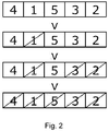
- each sub-phase is determined using a survey, rank, and freeze approach. Given an example that comprises five phases (see Figure 2 ), the sequence of actions taken by this rule scheme is listed as:
- the resulting outcome of this optimisation stage is the on/off state of the engines and generators, and the charge/discharge/inactive state of the energy storage system for every flight sub-phase (for the example discussed above).
- the power system set-points e.g. for each engine, generator, battery, or supercapacitor
- the proportions of power extracted from the generators to satisfy load demands are defined based on individual efficiency profiles and health status as well as the allowable tolerances on the load demands.
- the exact levels of power supported by the energy storage are also refined to ensure that the flexibility and potential of the power system is maximised in terms of the optimisation objective (which, in this example, is fuel cost minimisation).
- the power settings for each of the power components are restricted by the configuration set in the first layer of the two-scale optimisation.
- the optimisation methods used for this layer are, for example: a deterministic heuristic method, e.g. Nelder-Mead algorithm; and a stochastic heuristic method, e.g. particle swarm optimisation algorithm.
- a deterministic heuristic method e.g. Nelder-Mead algorithm
- a stochastic heuristic method e.g. particle swarm optimisation algorithm.
- the power settings for the power components for the entire flight have been determined, the power settings are fed back to the platform ready to be enacted on the power system.
- the system is in operation throughout the flight, and configurations set at the beginning of the flight may change depending on any real time flight updates.
- the rankings approach utilised in the survey, rank, and freeze approach may be replaced by a different set of rules.
- the sub-phases were ranked from most beneficial in terms of the objective to the least beneficial in terms of the objective.
- the fixing of the control parameters could also be done in order, or reverse order, of performance in time of the sub-phases.
- the computer-implemented method discussed above can be applied to optimise either a single or a plurality of objectives simultaneously.
- the relative importance of the criteria may change for each sub-phase, flight phase, operation mode, or mission.
- Measures of uncertainties can be incorporated into the optimisation process and, depending on the objectives of the optimisation, a different power plan may be enacted based on a solution selection rule or rules.
- a system utilising the above computer-implemented method could be applied within an autonomous vehicle context, where the mission goals and performance (optimisation) criteria are defined by another computer system (such as a mission management system).
- a human operator on-board, or remote may define the goals and objectives.
- the optimisation criteria may be singular or multiple, and static (for a flight) or dynamic (changing within the flight).
- Load tolerances which may be exploited include time tolerances or power (absolute) tolerances. These can be exploited in all of the stages of the method e.g. the feasibility checker and management (to ensure feasibility) as well as the greedy coarse mission power optimiser and the refined sub-phase mission power optimiser (for further optimisation).
- the present disclosure is applicable to optimization of the performance of reconfigurable power systems in vehicles generally, and indeed to optimization of the performance of reconfigurable power systems which may not be vehicular, e.g. static power generators.
- Embodiments may be described as a process which is depicted as a flowchart, a flow diagram, a data flow diagram, a structure diagram, or a block diagram. Although a flowchart may describe the operations as a sequential process, many of the operations can be performed in parallel or concurrently. In addition, the order of the operations may be rearranged. A process is terminated when its operations are completed, but could have additional steps not included in the figure. A process may correspond to a method, a function, a procedure, a subroutine, a subprogram, etc. When a process corresponds to a function, its termination corresponds to a return of the function to the calling function or the main function.
- computer readable medium may represent one or more devices for storing data, including read only memory (ROM), random access memory (RAM), magnetic RAM, core memory, magnetic disk storage mediums, optical storage mediums, flash memory devices and/or other machine readable mediums for storing information.
- ROM read only memory
- RAM random access memory
- magnetic RAM magnetic RAM
- core memory magnetic disk storage mediums
- optical storage mediums flash memory devices and/or other machine readable mediums for storing information.
- computer-readable medium includes, but is not limited to portable or fixed storage devices, optical storage devices, wireless channels and various other mediums capable of storing, containing or carrying instruction(s) and/or data.
- embodiments may be implemented by hardware, software, firmware, middleware, microcode, hardware description languages, or any combination thereof.
- the program code or code segments to perform the necessary tasks may be stored in a computer readable medium.
- One or more processors may perform the necessary tasks.
- a code segment may represent a procedure, a function, a subprogram, a program, a routine, a subroutine, a module, a software package, a class, or any combination of instructions, data structures, or program statements.
- a code segment may be coupled to another code segment or a hardware circuit by passing and/or receiving information, data, arguments, parameters, or memory contents. Information, arguments, parameters, data, etc. may be passed, forwarded, or transmitted via any suitable means including memory sharing, message passing, token passing, network transmission, etc.
Landscapes
- Engineering & Computer Science (AREA)
- Physics & Mathematics (AREA)
- General Physics & Mathematics (AREA)
- Aviation & Aerospace Engineering (AREA)
- Software Systems (AREA)
- Signal Processing (AREA)
- Computer Networks & Wireless Communication (AREA)
- Theoretical Computer Science (AREA)
- General Engineering & Computer Science (AREA)
- Supply And Distribution Of Alternating Current (AREA)
- Radar, Positioning & Navigation (AREA)
- Remote Sensing (AREA)
- Management, Administration, Business Operations System, And Electronic Commerce (AREA)
Abstract
Description
- The present disclosure relates to a computer-implemented method of optimizing the performance of a reconfigurable power system.
- Power system optimisation over a mission / operating profile, particularly in the context of vehicles such as aircraft, is generally treated as a finite horizon optimisation problem. At each time instance over the finite horizon of travel, the optimal configuration of the power system can be determined. There is a proposal to solve this as a model predictive control solution (Huang, Y. et al., 2017. Model predictive control power management strategies for HEVs: A review. Journal of Power Sources). However, solving the problem over the whole mission, with a full set of decision variables at each time step, is computationally challenging - particularly for non-linear systems. Similar problems can be confronted in relation to non-vehicular power systems, such as static power generators.
- Previously, a solution to this issue has been to decompose the problem hierarchically at different time scales. For example, it is known to decompose an electric ship power optimisation problem based on time scale i.e. based on the underlying physical dynamics of the power component (Xie, Y., Seenumani, G. & Sun, J., 2008. Real-time Simulation and Optimisation of Multi-scale Shipboard Power Systems. In Proc. Grand Challenges in Modelling and Simulation). However, this requires different models to be constructed, and assumes that the slow time scale can be modelled in a manner suitable for solving with an optimiser. In addition, the problem does not have determinism or convergence guarantees if the system at any time scale is non-linear.
- Accordingly, in a first aspect, there is provided a computer-implemented method of optimizing the performance of a reconfigurable power system, comprising the steps of:
- receiving an operating profile for the reconfigurable power system;
- partitioning the operating profile into a plurality of sub-phases;
- performing a coarse optimisation routine of the power system over each sub-phase of the operating profile to derive a respective coarsely optimised configuration of the power system;
- performing a fine optimisation routine of each coarsely optimised configuration over its respective sub-phase of the operating profile to derive a respective finely optimised configuration for that sub-phase; and
- defining settings of the power system to implement the finely optimised configurations thereon.
- Advantageously, this method provides an approach to solve complex, large-scale optimisation problems in a practical time frame. The coarse optimisation allows the sub-phases to be decoupled by fixing boundary conditions for the fine grained optimisation, thus allowing the fine grain optimisation to be solved more simply in independence of the other sub-phases. The optimisation may act to improve parameters such as: fuel consumption, power availability, power efficiency, and component health.
- The computer-implemented method may have any one or, to the extent that they are compatible, any combination of the following optional features.
- The reconfigurable power system can be a power system in a vehicle. The operating profile can then be a mission profile for the vehicle. The vehicle can be an aircraft, a ship, a train, an automobile etc. The mission profile can be appropriate to the type of vehicle. For example, a flight plan for an aircraft; a shipping route and schedule for a ship; a route, timetable, and railway network signalling information, speed limits, inclines, availability of overhead power lines etc. for a hybrid locomotive system; a route with different classes of environment for an automobile.
- The coarse optimisation routine may include the steps of: (a) estimating, for each sub-phase under consideration, a value of an output parameter to be optimised by varying control parameters of the power system; (b) ranking each sub-phase under consideration based on the estimated value, and determining a highest ranking sub-phase; (c) fixing those control parameters of the power system which allowed the power system to achieve the estimated value of the output parameter for the highest ranking sub-phase; (d) removing the highest ranking sub-phase from consideration; and (e) repeating steps (a) - (d) in order to fix control parameters of the power system in respect of sub-phases remaining under consideration. For example, the output parameter to be optimised may be fuel consumption, power availability, power efficiency, component health, response time/speed of response, maintenance cost, through-life cost (including capital expenditure and/or operational expenditure), emissions and/or environmental concerns, and/or energy trading costs (for example, if the power system is for land-based generation). For example, in the context of an aircraft power system, the control parameters may include an engine shut down status, an energy storage status, an energy generation status etc.
- In step (c) a control parameter fixed for the highest ranking sub-phase may impose a constraint on a control parameter of one or more other sub-phases under consideration such that the value of the constrained control parameter may be fixed for those sub-phases. For example, if in one sub-phase a control parameter requires that a battery must be used to power one or more motors, previous sub-phases may be constrained to (i) not use the power stored in that battery; (ii) use the power stored in that battery but leave a predetermined amount of energy in the battery; and/or (iii) place the battery in a charging state.
- The constraints imposed on the sub-phases for the coarse optimisation routine may be imposed on the sub-phases for the fine optimisation routine. Advantageously, the computational complexity of the fine optimisation routine may be reduced as a result.
- The computer-implemented method may include a step, performed before partitioning the operating profile, of receiving a condition of the power system and determining, based on the operating profile and the condition of the power system, whether a goal of the operating profile can be achieved. For example, the condition of the power system can be: fixed demands on the system, system resources, system restrictions, system health, expected power demands, change in resources (for example change in feasibility for planned engine shutdown, change in generator health and therefore advised operation regions) etc.
- Determining whether the goal of the operating profile can be achieved may include determining whether power available within the power system is sufficient to achieve the goal of the operating profile. If the determination is that the power available is insufficient, one or more power drains on the system may be disengaged based on predetermined priority levels of the power drains.
- Determining whether the goal of the operating profile can be achieved may include deriving an initial configuration of control parameters of the power system which allows the goal to be achieved, and this initial configuration may be the subject of the coarse optimisation routine.
- The coarse optimisation routine may use a set of heuristic optimisation rules. The coarse optimisation routine may use one or more greedy optimisation rules, which may consider a subset of control parameters by aggregating the control parameters. The use of a heuristic rule-based optimiser can ensure that the best configuration is set for each sub-phase, and can remove or reduce the need to iterate the process.
- The fine optimisation routine may use either a deterministic heuristic method; a stochastic heuristic method; or a hybrid thereof.
- Partitioning the operating profile may be based on any one or more of: a power demand tolerance; an environment allowance; an operation phase; component health information; an availability of one or more energy storage components; an environment in which a vehicle is to operate (e.g. significantly different altitudes, in which allowed noise and/or emissions levels may vary). For an aircraft, example operation phases may be different phases of flight. For a land-based energy generation, example phases may be different times during the day as energy trading costs and/or loads may vary in time.
- In a second aspect, there is provided a flight management computer, which is configured to perform the computer-implemented method of the first aspect, the reconfigurable power system being a power system in an aircraft, and the operating profile being a mission profile for the aircraft. The flight management computer of the second aspect may have any one of, or indeed insofar as they are compatible any combination of, the optional features of the first aspect.
- In a third aspect, there is provided an aircraft including the flight management computer of the second aspect.
- In a fourth aspect, there is provided a method of operating a reconfigurable power system, the method comprising the steps of: performing the computer-implemented method of the first aspect to optimize the performance of a reconfigurable power system; and operating the reconfigurable power system to perform the operating profile. The method of the fourth aspect may have any one of, or indeed insofar as they are compatible any combination of, the optional features of the first aspect.
- During the operation of the power system, either or both of: an updated operating profile, or an updated condition of the reconfigurable power system, may be received, and the step of performing the computer-implemented method may be repeated using the received updated operating profile and/or updated condition of the reconfigurable power system.
- Further aspects provide: a computer program comprising code which, when run on a computer, causes the computer to perform the computer-implemented method of the first aspect; a computer readable medium storing a computer program comprising code which, when run on a computer, causes the computer to perform the computer-implemented method of the first aspect; and a computer system programmed to perform the computer-implemented method of the first aspect.
- Embodiments of the invention will now be described by way of example with reference to the accompanying drawings in which:
- Figure 1
- shows a system overview for a computer-implemented method; and
- Figure 2
- shows an example of a survey, rank, and freeze approach.
- Aspects and embodiments of the present invention will now be discussed with reference to the accompanying figures. Further aspects and embodiments will be apparent to those skilled in the art. All documents mentioned in this text are incorporated herein by reference
- The disclosure herein describes an approach to solve complex, large-scale optimisation problems in a practicable and timely manner. The large-scale problem is decomposed into a set of interdependent optimisation sub-problems. Interdependent problems herein may refer to problems which cannot easily be separated, and where any one of the solutions may impact the other (dependent) solutions.
- In one example, an aircraft power system has a given mission profile including one or more mission goals and platform condition (which describes the fixed demands on the power system, power system resources, and power system restrictions), the method may first ensure the feasibility of the mission power demand and delivery by exploiting power system flexibility while complying with any restrictions. For example, if an energy storage is available and is needed to supply energy in a given flight sub-phase to essential loads, to ensure missions success, energy is reserved for this purpose. Then, by modelling the problem in two layers (coarse and detailed or fine) with a small set of shared boundary/initial conditions, a two-scale optimisation is introduced. The process can be optimised to reduce fuel consumption, increase component life, increase performance, or a combination thereof, simultaneously. The system overview is shown in
Figure 1 . - The power system demands may be expressed in power required as a function of the entire flight cycle. This may be described in more detail by expressing the power requirement by groups of loads (load banks) and the priority or critically of each load. The power system resources and restrictions are determined by the component themselves, e.g. power rating, losses, recharge lags, and component health.
- By verifying that the power available (e.g. of engines, generators, and energy storage) across the flight horizon is larger than the power demands across the flight horizon and that, within each phase, any restrictions are addressed such as certification limits, feasibility can be determined. If infeasible, additional power support from the energy storage system may then be considered. If still infeasible, loads may be dropped or disengaged from the power supply based on priorities or criticality. Any additional restrictions to the power sources (e.g. power store use during a particular sub-phase in flight to maintain feasibility) and changes to power demands (e.g. dropped low-priority loads) can be updated before passing onto the two-scale optimisation stage.
- In the first layer of the two-scale optimisation, a greedy set of heuristic optimisation rules can be used to pre-define the best expected power system set-up (or configuration) for each flight sub-phase, given overall mission demands and resources. Other control parameters may be aggregated to save computational / assessment time. At the onset of this layer of optimisation, the mission profile is partitioned into a plurality of sub-phases. In this example, the sub-phases are defined based on mission information, environment, and component status, health, and capacities.
- As an illustrative example, consider a power system with two engines with two generators each and an energy storage system, where the optimisation objective is set to reduce fuel consumption. A configuration of the power system for a given flight sub-phase may be that only one engine is switched on (where the planned engine in-flight shutdown is allowable for the other engine), resulting in only two of the generators providing power to the power bus, along with the support from the energy storage. The configuration in this sub-phase also necessitates the configuration of the previous sub-phase to define the energy storage state as being recharged.
- More generally, the configuration for each sub-phase is determined using a survey, rank, and freeze approach. Given an example that comprises five phases (see
Figure 2 ), the sequence of actions taken by this rule scheme is listed as: - 1. Estimate fuel consumption for each sub-phase if engine shutdown is permitted according to airspace regulations and mission demands. Use of the energy storage is also enabled to support generators, encouraging improved efficiency of the generators. The fuel consumption is estimated by setting the power output of the active generators to be of equal proportions and equal thrust loads on engines (if both engines are on). Rank each sub-phase based on the expected fuel consumption (where a rank of 1 indicates the least fuel consumption).
- 2. Fix the configuration of control parameters of the system to satisfy the preferred configuration of the
rank 1 phase (i.e. Sub-phase 2 in the example shown inFigure 2 ). Update the constraints that are affected by this for sub-phases before and afterSub-phase 2. That is, other sub-phases whose control parameters cannot be modified also have those control parameters fixed. For example, ifSub-phase 2 requires all energy stored in the energy storage, the energy of the energy storage will no longer be available for the sub-phase immediately precedingSub-phase 2. Fixing here indicates that the relevant control parameters of the sub-phase are frozen and cannot be further modified. - 3. Go to the next best-ranked phase (rank 2) i.e. Sub-phase 5. Fix the configuration of control parameters that favours the reduction of fuel use in
Sub-phase 5. Again, constrained control parameters for the remaining sub-phases under consideration are also fixed accordingly. For this example, Sub-phase 4 is fixed along withSub-phase 5. - 4.
Step 3 is repeated until all sub-phases have been considered and their configurations fixed. - 5. Steps 1 - 4 can be repeated for cases where planned engine in-flight shutdown is disabled and for cases where planned engine in-flight shutdown and energy storage use are disabled, resulting in three potential configuration sets. Engine in-flight shutdown costs (if any) are incorporated and the configuration set with the least fuel consumed is selected for optimisation.
- The resulting outcome of this optimisation stage is the on/off state of the engines and generators, and the charge/discharge/inactive state of the energy storage system for every flight sub-phase (for the example discussed above).
- In the second layer of the two-scale optimisation, a more in-depth optimisation process takes place, where the power system set-points (e.g. for each engine, generator, battery, or supercapacitor) are defined by exploiting system behaviour and mission tolerances. For example, the proportions of power extracted from the generators to satisfy load demands are defined based on individual efficiency profiles and health status as well as the allowable tolerances on the load demands. The exact levels of power supported by the energy storage are also refined to ensure that the flexibility and potential of the power system is maximised in terms of the optimisation objective (which, in this example, is fuel cost minimisation). The power settings for each of the power components are restricted by the configuration set in the first layer of the two-scale optimisation.
- The optimisation methods used for this layer are, for example: a deterministic heuristic method, e.g. Nelder-Mead algorithm; and a stochastic heuristic method, e.g. particle swarm optimisation algorithm.
- Once the power settings for the power components for the entire flight have been determined, the power settings are fed back to the platform ready to be enacted on the power system.
- The system is in operation throughout the flight, and configurations set at the beginning of the flight may change depending on any real time flight updates.
- The rankings approach utilised in the survey, rank, and freeze approach may be replaced by a different set of rules. For example, in the approach discussed previously, the sub-phases were ranked from most beneficial in terms of the objective to the least beneficial in terms of the objective. However, the fixing of the control parameters could also be done in order, or reverse order, of performance in time of the sub-phases.
- The computer-implemented method discussed above can be applied to optimise either a single or a plurality of objectives simultaneously. For optimisation against multiple criteria, the relative importance of the criteria may change for each sub-phase, flight phase, operation mode, or mission. Measures of uncertainties can be incorporated into the optimisation process and, depending on the objectives of the optimisation, a different power plan may be enacted based on a solution selection rule or rules.
- A system utilising the above computer-implemented method could be applied within an autonomous vehicle context, where the mission goals and performance (optimisation) criteria are defined by another computer system (such as a mission management system). Alternatively, a human operator (on-board, or remote) may define the goals and objectives.
- The optimisation criteria may be singular or multiple, and static (for a flight) or dynamic (changing within the flight).
- Load tolerances which may be exploited include time tolerances or power (absolute) tolerances. These can be exploited in all of the stages of the method e.g. the feasibility checker and management (to ensure feasibility) as well as the greedy coarse mission power optimiser and the refined sub-phase mission power optimiser (for further optimisation).
- Although described above in relation to an aircraft power system having a given mission profile, the present disclosure is applicable to optimization of the performance of reconfigurable power systems in vehicles generally, and indeed to optimization of the performance of reconfigurable power systems which may not be vehicular, e.g. static power generators.
- Embodiments may be described as a process which is depicted as a flowchart, a flow diagram, a data flow diagram, a structure diagram, or a block diagram. Although a flowchart may describe the operations as a sequential process, many of the operations can be performed in parallel or concurrently. In addition, the order of the operations may be rearranged. A process is terminated when its operations are completed, but could have additional steps not included in the figure. A process may correspond to a method, a function, a procedure, a subroutine, a subprogram, etc. When a process corresponds to a function, its termination corresponds to a return of the function to the calling function or the main function.
- The term "computer readable medium" may represent one or more devices for storing data, including read only memory (ROM), random access memory (RAM), magnetic RAM, core memory, magnetic disk storage mediums, optical storage mediums, flash memory devices and/or other machine readable mediums for storing information. The term "computer-readable medium" includes, but is not limited to portable or fixed storage devices, optical storage devices, wireless channels and various other mediums capable of storing, containing or carrying instruction(s) and/or data.
- Furthermore, embodiments may be implemented by hardware, software, firmware, middleware, microcode, hardware description languages, or any combination thereof. When implemented in software, firmware, middleware or microcode, the program code or code segments to perform the necessary tasks may be stored in a computer readable medium. One or more processors may perform the necessary tasks. A code segment may represent a procedure, a function, a subprogram, a program, a routine, a subroutine, a module, a software package, a class, or any combination of instructions, data structures, or program statements. A code segment may be coupled to another code segment or a hardware circuit by passing and/or receiving information, data, arguments, parameters, or memory contents. Information, arguments, parameters, data, etc. may be passed, forwarded, or transmitted via any suitable means including memory sharing, message passing, token passing, network transmission, etc.
- While the invention has been described in conjunction with the exemplary embodiments described above, many equivalent modifications and variations will be apparent to those skilled in the art when given this disclosure but within the scope of the following claims. Accordingly, the exemplary embodiments of the invention set forth above are considered to be illustrative and not limiting.
Claims (15)
- A computer-implemented method of optimizing the performance of a reconfigurable power system, comprising the steps of:receiving an operating profile for the reconfigurable power system;partitioning the operating profile into a plurality of sub-phases;performing a coarse optimisation routine of the power system over each sub-phase of the operating profile to derive a respective coarsely optimised configuration of the power system;performing a fine optimisation routine of each coarsely optimised configuration over its respective sub-phase of the operating profile to derive a respective finely optimised configuration for that sub-phase; anddefining settings of the power system to implement the finely optimised configurations thereon.
- The computer-implemented method of claim 1, wherein the coarse optimisation routine includes the steps of:(a) estimating, for each sub-phase under consideration, a value of an output parameter to be optimised by varying control parameters of the power system;(b) ranking each sub-phase under consideration based on the estimated value, and determining a highest ranking sub-phase;(c) fixing those control parameters of the power system which allowed the power system to achieve the estimated value of the output parameter for the highest ranking sub-phase;(d) removing the highest ranking sub-phase from consideration; and(e) repeating steps (a) - (d) in order to fix control parameters of the power system in respect of sub-phases remaining under consideration.
- The computer-implemented method of claim 2, wherein in step (c) a control parameter fixed for the highest ranking sub-phase imposes a constraint on a control parameter of one or more other sub-phases under consideration such that the value of the constrained control parameter is fixed for those sub-phases.
- The computer-implemented method of claim 3, wherein constraints imposed on the sub-phases for the coarse optimisation routine are imposed on the sub-phases for the fine optimisation routine.
- The computer-implemented method of any preceding claim, also comprising a step, performed before partitioning the operating profile, of receiving a condition of the power system and determining, based on the operating profile and the condition of the power system, whether a goal of the operating profile can be achieved.
- The computer-implemented method of claim 5, wherein determining whether the goal of the operating profile can be achieved includes determining whether power available within the power system is sufficient to achieve the goal of the operating profile.
- The computer-implemented method of claim 6, wherein if the determination is that the power available is insufficient, one or more power drains on the system are disengaged based on predetermined priority levels of the power drains.
- The computer-implemented method of any one of claims 5 to 7, wherein determining whether the goal of the operating profile can be achieved includes deriving an initial configuration of control parameters of the power system which allows the goal to be achieved, and wherein this initial configuration is the subject of the coarse optimisation routine.
- The computer-implemented method of any preceding claim, wherein the coarse optimisation routine uses a set of heuristic optimisation rules.
- The computer-implemented method of any preceding claim, wherein the fine optimisation routine uses either a deterministic heuristic method; a stochastic heuristic method; or a hybrid thereof.
- The computer-implemented method of any preceding claim, wherein partitioning the operating profile is based on any one or more of: a power demand tolerance; an environment allowance; an operation phase; component health information; and an availability of one or more energy storage components.
- The computer-implemented method of any preceding claim, wherein the reconfigurable power system is a reconfigurable power system in a vehicle, and wherein the operating profile is a mission profile for the vehicle.
- A flight management computer configured to perform the computer-implemented method of claim 12.
- An aircraft including the flight management computer of claim 13.
- A procedure of operating a reconfigurable power system, the procedure comprising the steps of:performing the computer-implemented method of any one of claims 1 to 12 to optimize the performance of the reconfigurable power system; andoperating the reconfigurable power system to perform the operating profile.
Applications Claiming Priority (1)
| Application Number | Priority Date | Filing Date | Title |
|---|---|---|---|
| GBGB1900477.9A GB201900477D0 (en) | 2019-01-14 | 2019-01-14 | Optimisation method |
Publications (2)
| Publication Number | Publication Date |
|---|---|
| EP3681104A1 true EP3681104A1 (en) | 2020-07-15 |
| EP3681104B1 EP3681104B1 (en) | 2023-02-01 |
Family
ID=65528095
Family Applications (1)
| Application Number | Title | Priority Date | Filing Date |
|---|---|---|---|
| EP19216956.3A Active EP3681104B1 (en) | 2019-01-14 | 2019-12-17 | Optimisation method |
Country Status (4)
| Country | Link |
|---|---|
| US (1) | US11308817B2 (en) |
| EP (1) | EP3681104B1 (en) |
| CN (1) | CN111506355B (en) |
| GB (1) | GB201900477D0 (en) |
Families Citing this family (1)
| Publication number | Priority date | Publication date | Assignee | Title |
|---|---|---|---|---|
| CN119989536B (en) * | 2025-01-24 | 2026-03-27 | 北京航空航天大学 | A method, apparatus, equipment, and medium for spacecraft pulse orbit control fuel optimization based on particle swarm optimization algorithm. |
Citations (2)
| Publication number | Priority date | Publication date | Assignee | Title |
|---|---|---|---|---|
| US20080058998A1 (en) * | 2006-08-29 | 2008-03-06 | The Boeing Company | Method and system for adaptive power management |
| EP2595011A2 (en) * | 2011-11-15 | 2013-05-22 | Palo Alto Research Center Incorporated | Using planning to control demand response and supply choices in a managed electrical system |
Family Cites Families (12)
| Publication number | Priority date | Publication date | Assignee | Title |
|---|---|---|---|---|
| RU2138840C1 (en) | 1994-07-08 | 1999-09-27 | Сименс АГ | Power plant control system |
| US7011498B2 (en) | 1998-04-03 | 2006-03-14 | Athena Technologies, Inc. | Optimization method for power generation systems |
| FR2856818B1 (en) * | 2003-06-30 | 2006-06-30 | Everbee Networks | METHOD AND SYSTEM FOR SEMANTICALLY CONTROLLING A DATA STREAM |
| CN100492286C (en) * | 2007-02-02 | 2009-05-27 | 浙江大学 | Performance optimization design method for graph library of embedded system development platform |
| US8185298B2 (en) * | 2007-10-17 | 2012-05-22 | Lockheed Martin Corporation | Hybrid heuristic national airspace flight path optimization |
| WO2012088537A1 (en) | 2010-12-23 | 2012-06-28 | Cummins Intellectual Property, Inc. | System and method of vehicle operating condition management |
| US9811130B2 (en) * | 2011-09-12 | 2017-11-07 | The Boeing Company | Power management control system |
| GB201200700D0 (en) * | 2012-01-17 | 2012-02-29 | Rolls Royce Plc | Vehicle energy and power management method and system |
| GB2524772B (en) | 2014-04-02 | 2016-07-13 | Rolls Royce Plc | Aircraft vapour trail control system |
| JP2017527059A (en) * | 2014-08-29 | 2017-09-14 | ズーナム エアロ,インコーポレイテッド | System and method for implementing a regional air traffic network using a hybrid electric airplane |
| EP2998817B1 (en) * | 2014-09-16 | 2017-06-07 | Aviovision | System for calculating aircraft performance and method for performing the same |
| CN106786687B (en) * | 2017-02-24 | 2019-11-15 | 深圳市微埃智能科技有限公司 | The method for parameter configuration and system of energy storage device |
-
2019
- 2019-01-14 GB GBGB1900477.9A patent/GB201900477D0/en not_active Ceased
- 2019-12-17 EP EP19216956.3A patent/EP3681104B1/en active Active
-
2020
- 2020-01-09 CN CN202010021063.0A patent/CN111506355B/en active Active
- 2020-01-10 US US16/739,614 patent/US11308817B2/en active Active
Patent Citations (2)
| Publication number | Priority date | Publication date | Assignee | Title |
|---|---|---|---|---|
| US20080058998A1 (en) * | 2006-08-29 | 2008-03-06 | The Boeing Company | Method and system for adaptive power management |
| EP2595011A2 (en) * | 2011-11-15 | 2013-05-22 | Palo Alto Research Center Incorporated | Using planning to control demand response and supply choices in a managed electrical system |
Non-Patent Citations (1)
| Title |
|---|
| HUANG, Y. ET AL.: "Model predictive control power management strategies for HEVs: A review", JOURNAL OF POWER SOURCES, 2017 |
Also Published As
| Publication number | Publication date |
|---|---|
| US11308817B2 (en) | 2022-04-19 |
| CN111506355B (en) | 2023-11-17 |
| EP3681104B1 (en) | 2023-02-01 |
| CN111506355A (en) | 2020-08-07 |
| GB201900477D0 (en) | 2019-02-27 |
| US20200226936A1 (en) | 2020-07-16 |
Similar Documents
| Publication | Publication Date | Title |
|---|---|---|
| Xie et al. | Optimization-based power and energy management system in shipboard microgrid: A review | |
| US9108652B2 (en) | Method and system for timetable optimization utilizing energy consumption factors | |
| US10202133B2 (en) | Method and system for timetable optimization utilizing energy consumption factors | |
| Hernández-Arauzo et al. | Electric vehicle charging under power and balance constraints as dynamic scheduling | |
| Rigas et al. | EVLibSim: A tool for the simulation of electric vehicles’ charging stations using the EVLib library | |
| EP2595011B1 (en) | Using planning to control demand response and supply choices in a managed electrical system | |
| Çinar | A methodology for dynamic sizing of electric power generation and distribution architectures | |
| Ozay et al. | Distributed power allocation for vehicle management systems | |
| US20230274216A1 (en) | Delivery plan generation apparatus, delivery plan generation method, and program | |
| Rigas et al. | Scheduling aerial vehicles in large scale urban air mobility schemes with vehicle relocation | |
| EP3681104B1 (en) | Optimisation method | |
| US12269368B2 (en) | Method of operating an energy management system for a fleet of aircraft | |
| André | Sustainable design of electric vertical take-off and landing aircraft for urban air mobility | |
| Wen et al. | Resilient microgrid scheduling with synthetic inertia from electric vehicles within a network of charging stations | |
| Elbert | Noncausal and causal optimization strategies for hybrid electric vehicles | |
| Kovač et al. | Variable neighborhood search methods for the dynamic minimum cost hybrid berth allocation problem | |
| Shen et al. | Minimum Cost Flow‐Based Integrated Model for Electric Vehicle and Crew Scheduling | |
| US12506345B2 (en) | Aircraft and method of operating an aircraft power system module | |
| Hellgren et al. | Early integration of quadratic programming-based power split control in electric aircraft charging system design | |
| Schattenberg et al. | On the Identification and Use of Hierarchical Resources in Planning and Scheduling. | |
| US11507077B2 (en) | Data analysis for selecting container with integrated energy source based on predicted transport energy usage | |
| US12630036B2 (en) | Systems and methods for optimal control of electric vehicle fleet and charging infrastructure | |
| US20240343149A1 (en) | Systems and methods for optimal control of electric vehicle fleet and charging infrastructure | |
| CN120735963B (en) | Energy scheduling method and system for distributed electric propulsion aircraft | |
| Arulmozhi et al. | Analysis of Power Requirements and Power Management using Various Optimization Techniques for Electric and Hybrid Electric Vehicles |
Legal Events
| Date | Code | Title | Description |
|---|---|---|---|
| PUAI | Public reference made under article 153(3) epc to a published international application that has entered the european phase |
Free format text: ORIGINAL CODE: 0009012 |
|
| STAA | Information on the status of an ep patent application or granted ep patent |
Free format text: STATUS: THE APPLICATION HAS BEEN PUBLISHED |
|
| AK | Designated contracting states |
Kind code of ref document: A1 Designated state(s): AL AT BE BG CH CY CZ DE DK EE ES FI FR GB GR HR HU IE IS IT LI LT LU LV MC MK MT NL NO PL PT RO RS SE SI SK SM TR |
|
| AX | Request for extension of the european patent |
Extension state: BA ME |
|
| STAA | Information on the status of an ep patent application or granted ep patent |
Free format text: STATUS: REQUEST FOR EXAMINATION WAS MADE |
|
| 17P | Request for examination filed |
Effective date: 20210112 |
|
| RBV | Designated contracting states (corrected) |
Designated state(s): AL AT BE BG CH CY CZ DE DK EE ES FI FR GB GR HR HU IE IS IT LI LT LU LV MC MK MT NL NO PL PT RO RS SE SI SK SM TR |
|
| STAA | Information on the status of an ep patent application or granted ep patent |
Free format text: STATUS: EXAMINATION IS IN PROGRESS |
|
| 17Q | First examination report despatched |
Effective date: 20210528 |
|
| REG | Reference to a national code |
Ref country code: DE Ref legal event code: R079 Ref document number: 602019025005 Country of ref document: DE Free format text: PREVIOUS MAIN CLASS: H04L0012240000 Ipc: H04L0041082300 |
|
| GRAP | Despatch of communication of intention to grant a patent |
Free format text: ORIGINAL CODE: EPIDOSNIGR1 |
|
| STAA | Information on the status of an ep patent application or granted ep patent |
Free format text: STATUS: GRANT OF PATENT IS INTENDED |
|
| GRAS | Grant fee paid |
Free format text: ORIGINAL CODE: EPIDOSNIGR3 |
|
| RIC1 | Information provided on ipc code assigned before grant |
Ipc: H04L 41/0833 20220101ALI20221021BHEP Ipc: H04L 41/0823 20220101AFI20221021BHEP |
|
| INTG | Intention to grant announced |
Effective date: 20221110 |
|
| GRAA | (expected) grant |
Free format text: ORIGINAL CODE: 0009210 |
|
| STAA | Information on the status of an ep patent application or granted ep patent |
Free format text: STATUS: THE PATENT HAS BEEN GRANTED |
|
| AK | Designated contracting states |
Kind code of ref document: B1 Designated state(s): AL AT BE BG CH CY CZ DE DK EE ES FI FR GB GR HR HU IE IS IT LI LT LU LV MC MK MT NL NO PL PT RO RS SE SI SK SM TR |
|
| REG | Reference to a national code |
Ref country code: GB Ref legal event code: FG4D |
|
| REG | Reference to a national code |
Ref country code: CH Ref legal event code: EP Ref country code: AT Ref legal event code: REF Ref document number: 1547211 Country of ref document: AT Kind code of ref document: T Effective date: 20230215 |
|
| REG | Reference to a national code |
Ref country code: DE Ref legal event code: R096 Ref document number: 602019025005 Country of ref document: DE |
|
| REG | Reference to a national code |
Ref country code: IE Ref legal event code: FG4D |
|
| REG | Reference to a national code |
Ref country code: LT Ref legal event code: MG9D |
|
| REG | Reference to a national code |
Ref country code: NL Ref legal event code: MP Effective date: 20230201 |
|
| P01 | Opt-out of the competence of the unified patent court (upc) registered |
Effective date: 20230528 |
|
| REG | Reference to a national code |
Ref country code: AT Ref legal event code: MK05 Ref document number: 1547211 Country of ref document: AT Kind code of ref document: T Effective date: 20230201 |
|
| PG25 | Lapsed in a contracting state [announced via postgrant information from national office to epo] |
Ref country code: RS Free format text: LAPSE BECAUSE OF FAILURE TO SUBMIT A TRANSLATION OF THE DESCRIPTION OR TO PAY THE FEE WITHIN THE PRESCRIBED TIME-LIMIT Effective date: 20230201 Ref country code: PT Free format text: LAPSE BECAUSE OF FAILURE TO SUBMIT A TRANSLATION OF THE DESCRIPTION OR TO PAY THE FEE WITHIN THE PRESCRIBED TIME-LIMIT Effective date: 20230601 Ref country code: NO Free format text: LAPSE BECAUSE OF FAILURE TO SUBMIT A TRANSLATION OF THE DESCRIPTION OR TO PAY THE FEE WITHIN THE PRESCRIBED TIME-LIMIT Effective date: 20230501 Ref country code: NL Free format text: LAPSE BECAUSE OF FAILURE TO SUBMIT A TRANSLATION OF THE DESCRIPTION OR TO PAY THE FEE WITHIN THE PRESCRIBED TIME-LIMIT Effective date: 20230201 Ref country code: LV Free format text: LAPSE BECAUSE OF FAILURE TO SUBMIT A TRANSLATION OF THE DESCRIPTION OR TO PAY THE FEE WITHIN THE PRESCRIBED TIME-LIMIT Effective date: 20230201 Ref country code: LT Free format text: LAPSE BECAUSE OF FAILURE TO SUBMIT A TRANSLATION OF THE DESCRIPTION OR TO PAY THE FEE WITHIN THE PRESCRIBED TIME-LIMIT Effective date: 20230201 Ref country code: HR Free format text: LAPSE BECAUSE OF FAILURE TO SUBMIT A TRANSLATION OF THE DESCRIPTION OR TO PAY THE FEE WITHIN THE PRESCRIBED TIME-LIMIT Effective date: 20230201 Ref country code: ES Free format text: LAPSE BECAUSE OF FAILURE TO SUBMIT A TRANSLATION OF THE DESCRIPTION OR TO PAY THE FEE WITHIN THE PRESCRIBED TIME-LIMIT Effective date: 20230201 Ref country code: AT Free format text: LAPSE BECAUSE OF FAILURE TO SUBMIT A TRANSLATION OF THE DESCRIPTION OR TO PAY THE FEE WITHIN THE PRESCRIBED TIME-LIMIT Effective date: 20230201 |
|
| PG25 | Lapsed in a contracting state [announced via postgrant information from national office to epo] |
Ref country code: SE Free format text: LAPSE BECAUSE OF FAILURE TO SUBMIT A TRANSLATION OF THE DESCRIPTION OR TO PAY THE FEE WITHIN THE PRESCRIBED TIME-LIMIT Effective date: 20230201 Ref country code: PL Free format text: LAPSE BECAUSE OF FAILURE TO SUBMIT A TRANSLATION OF THE DESCRIPTION OR TO PAY THE FEE WITHIN THE PRESCRIBED TIME-LIMIT Effective date: 20230201 Ref country code: IS Free format text: LAPSE BECAUSE OF FAILURE TO SUBMIT A TRANSLATION OF THE DESCRIPTION OR TO PAY THE FEE WITHIN THE PRESCRIBED TIME-LIMIT Effective date: 20230601 Ref country code: GR Free format text: LAPSE BECAUSE OF FAILURE TO SUBMIT A TRANSLATION OF THE DESCRIPTION OR TO PAY THE FEE WITHIN THE PRESCRIBED TIME-LIMIT Effective date: 20230502 Ref country code: FI Free format text: LAPSE BECAUSE OF FAILURE TO SUBMIT A TRANSLATION OF THE DESCRIPTION OR TO PAY THE FEE WITHIN THE PRESCRIBED TIME-LIMIT Effective date: 20230201 |
|
| PG25 | Lapsed in a contracting state [announced via postgrant information from national office to epo] |
Ref country code: SM Free format text: LAPSE BECAUSE OF FAILURE TO SUBMIT A TRANSLATION OF THE DESCRIPTION OR TO PAY THE FEE WITHIN THE PRESCRIBED TIME-LIMIT Effective date: 20230201 Ref country code: RO Free format text: LAPSE BECAUSE OF FAILURE TO SUBMIT A TRANSLATION OF THE DESCRIPTION OR TO PAY THE FEE WITHIN THE PRESCRIBED TIME-LIMIT Effective date: 20230201 Ref country code: EE Free format text: LAPSE BECAUSE OF FAILURE TO SUBMIT A TRANSLATION OF THE DESCRIPTION OR TO PAY THE FEE WITHIN THE PRESCRIBED TIME-LIMIT Effective date: 20230201 Ref country code: DK Free format text: LAPSE BECAUSE OF FAILURE TO SUBMIT A TRANSLATION OF THE DESCRIPTION OR TO PAY THE FEE WITHIN THE PRESCRIBED TIME-LIMIT Effective date: 20230201 Ref country code: CZ Free format text: LAPSE BECAUSE OF FAILURE TO SUBMIT A TRANSLATION OF THE DESCRIPTION OR TO PAY THE FEE WITHIN THE PRESCRIBED TIME-LIMIT Effective date: 20230201 |
|
| REG | Reference to a national code |
Ref country code: DE Ref legal event code: R097 Ref document number: 602019025005 Country of ref document: DE |
|
| PG25 | Lapsed in a contracting state [announced via postgrant information from national office to epo] |
Ref country code: SK Free format text: LAPSE BECAUSE OF FAILURE TO SUBMIT A TRANSLATION OF THE DESCRIPTION OR TO PAY THE FEE WITHIN THE PRESCRIBED TIME-LIMIT Effective date: 20230201 |
|
| PLBE | No opposition filed within time limit |
Free format text: ORIGINAL CODE: 0009261 |
|
| STAA | Information on the status of an ep patent application or granted ep patent |
Free format text: STATUS: NO OPPOSITION FILED WITHIN TIME LIMIT |
|
| 26N | No opposition filed |
Effective date: 20231103 |
|
| PG25 | Lapsed in a contracting state [announced via postgrant information from national office to epo] |
Ref country code: SI Free format text: LAPSE BECAUSE OF FAILURE TO SUBMIT A TRANSLATION OF THE DESCRIPTION OR TO PAY THE FEE WITHIN THE PRESCRIBED TIME-LIMIT Effective date: 20230201 |
|
| PG25 | Lapsed in a contracting state [announced via postgrant information from national office to epo] |
Ref country code: IT Free format text: LAPSE BECAUSE OF FAILURE TO SUBMIT A TRANSLATION OF THE DESCRIPTION OR TO PAY THE FEE WITHIN THE PRESCRIBED TIME-LIMIT Effective date: 20230201 |
|
| REG | Reference to a national code |
Ref country code: CH Ref legal event code: PL |
|
| PG25 | Lapsed in a contracting state [announced via postgrant information from national office to epo] |
Ref country code: LU Free format text: LAPSE BECAUSE OF NON-PAYMENT OF DUE FEES Effective date: 20231217 |
|
| PG25 | Lapsed in a contracting state [announced via postgrant information from national office to epo] |
Ref country code: MC Free format text: LAPSE BECAUSE OF FAILURE TO SUBMIT A TRANSLATION OF THE DESCRIPTION OR TO PAY THE FEE WITHIN THE PRESCRIBED TIME-LIMIT Effective date: 20230201 |
|
| REG | Reference to a national code |
Ref country code: BE Ref legal event code: MM Effective date: 20231231 |
|
| PG25 | Lapsed in a contracting state [announced via postgrant information from national office to epo] |
Ref country code: MC Free format text: LAPSE BECAUSE OF FAILURE TO SUBMIT A TRANSLATION OF THE DESCRIPTION OR TO PAY THE FEE WITHIN THE PRESCRIBED TIME-LIMIT Effective date: 20230201 Ref country code: LU Free format text: LAPSE BECAUSE OF NON-PAYMENT OF DUE FEES Effective date: 20231217 |
|
| REG | Reference to a national code |
Ref country code: IE Ref legal event code: MM4A |
|
| PG25 | Lapsed in a contracting state [announced via postgrant information from national office to epo] |
Ref country code: IE Free format text: LAPSE BECAUSE OF NON-PAYMENT OF DUE FEES Effective date: 20231217 |
|
| PG25 | Lapsed in a contracting state [announced via postgrant information from national office to epo] |
Ref country code: BE Free format text: LAPSE BECAUSE OF NON-PAYMENT OF DUE FEES Effective date: 20231231 |
|
| PG25 | Lapsed in a contracting state [announced via postgrant information from national office to epo] |
Ref country code: CH Free format text: LAPSE BECAUSE OF NON-PAYMENT OF DUE FEES Effective date: 20231231 |
|
| PG25 | Lapsed in a contracting state [announced via postgrant information from national office to epo] |
Ref country code: IE Free format text: LAPSE BECAUSE OF NON-PAYMENT OF DUE FEES Effective date: 20231217 Ref country code: CH Free format text: LAPSE BECAUSE OF NON-PAYMENT OF DUE FEES Effective date: 20231231 Ref country code: BE Free format text: LAPSE BECAUSE OF NON-PAYMENT OF DUE FEES Effective date: 20231231 |
|
| PG25 | Lapsed in a contracting state [announced via postgrant information from national office to epo] |
Ref country code: BG Free format text: LAPSE BECAUSE OF FAILURE TO SUBMIT A TRANSLATION OF THE DESCRIPTION OR TO PAY THE FEE WITHIN THE PRESCRIBED TIME-LIMIT Effective date: 20230201 |
|
| PG25 | Lapsed in a contracting state [announced via postgrant information from national office to epo] |
Ref country code: BG Free format text: LAPSE BECAUSE OF FAILURE TO SUBMIT A TRANSLATION OF THE DESCRIPTION OR TO PAY THE FEE WITHIN THE PRESCRIBED TIME-LIMIT Effective date: 20230201 |
|
| PG25 | Lapsed in a contracting state [announced via postgrant information from national office to epo] |
Ref country code: CY Free format text: LAPSE BECAUSE OF FAILURE TO SUBMIT A TRANSLATION OF THE DESCRIPTION OR TO PAY THE FEE WITHIN THE PRESCRIBED TIME-LIMIT; INVALID AB INITIO Effective date: 20191217 |
|
| PG25 | Lapsed in a contracting state [announced via postgrant information from national office to epo] |
Ref country code: HU Free format text: LAPSE BECAUSE OF FAILURE TO SUBMIT A TRANSLATION OF THE DESCRIPTION OR TO PAY THE FEE WITHIN THE PRESCRIBED TIME-LIMIT; INVALID AB INITIO Effective date: 20191217 |
|
| PG25 | Lapsed in a contracting state [announced via postgrant information from national office to epo] |
Ref country code: TR Free format text: LAPSE BECAUSE OF FAILURE TO SUBMIT A TRANSLATION OF THE DESCRIPTION OR TO PAY THE FEE WITHIN THE PRESCRIBED TIME-LIMIT Effective date: 20230201 |
|
| PGFP | Annual fee paid to national office [announced via postgrant information from national office to epo] |
Ref country code: GB Payment date: 20251223 Year of fee payment: 7 |
|
| PGFP | Annual fee paid to national office [announced via postgrant information from national office to epo] |
Ref country code: FR Payment date: 20251230 Year of fee payment: 7 |
|
| PGFP | Annual fee paid to national office [announced via postgrant information from national office to epo] |
Ref country code: DE Payment date: 20251229 Year of fee payment: 7 |