EP3681024A1 - Electrical machine disconnection systems - Google Patents
Electrical machine disconnection systems Download PDFInfo
- Publication number
- EP3681024A1 EP3681024A1 EP19209259.1A EP19209259A EP3681024A1 EP 3681024 A1 EP3681024 A1 EP 3681024A1 EP 19209259 A EP19209259 A EP 19209259A EP 3681024 A1 EP3681024 A1 EP 3681024A1
- Authority
- EP
- European Patent Office
- Prior art keywords
- rotor
- shaft
- stator
- relative
- move
- Prior art date
- Legal status (The legal status is an assumption and is not a legal conclusion. Google has not performed a legal analysis and makes no representation as to the accuracy of the status listed.)
- Granted
Links
Images




Classifications
-
- H—ELECTRICITY
- H02—GENERATION; CONVERSION OR DISTRIBUTION OF ELECTRIC POWER
- H02K—DYNAMO-ELECTRIC MACHINES
- H02K21/00—Synchronous motors having permanent magnets; Synchronous generators having permanent magnets
- H02K21/02—Details
- H02K21/021—Means for mechanical adjustment of the excitation flux
- H02K21/022—Means for mechanical adjustment of the excitation flux by modifying the relative position between field and armature, e.g. between rotor and stator
- H02K21/023—Means for mechanical adjustment of the excitation flux by modifying the relative position between field and armature, e.g. between rotor and stator by varying the amount of superposition, i.e. the overlap, of field and armature
- H02K21/024—Radial air gap machines
-
- H—ELECTRICITY
- H02—GENERATION; CONVERSION OR DISTRIBUTION OF ELECTRIC POWER
- H02K—DYNAMO-ELECTRIC MACHINES
- H02K21/00—Synchronous motors having permanent magnets; Synchronous generators having permanent magnets
- H02K21/02—Details
- H02K21/021—Means for mechanical adjustment of the excitation flux
- H02K21/028—Means for mechanical adjustment of the excitation flux by modifying the magnetic circuit within the field or the armature, e.g. by using shunts, by adjusting the magnets position, by vectorial combination of field or armature sections
-
- H—ELECTRICITY
- H02—GENERATION; CONVERSION OR DISTRIBUTION OF ELECTRIC POWER
- H02K—DYNAMO-ELECTRIC MACHINES
- H02K21/00—Synchronous motors having permanent magnets; Synchronous generators having permanent magnets
- H02K21/12—Synchronous motors having permanent magnets; Synchronous generators having permanent magnets with stationary armatures and rotating magnets
- H02K21/14—Synchronous motors having permanent magnets; Synchronous generators having permanent magnets with stationary armatures and rotating magnets with magnets rotating within the armatures
-
- H—ELECTRICITY
- H02—GENERATION; CONVERSION OR DISTRIBUTION OF ELECTRIC POWER
- H02K—DYNAMO-ELECTRIC MACHINES
- H02K2213/00—Specific aspects, not otherwise provided for and not covered by codes H02K2201/00 - H02K2211/00
- H02K2213/09—Machines characterised by the presence of elements which are subject to variation, e.g. adjustable bearings, reconfigurable windings, variable pitch ventilators
-
- Y—GENERAL TAGGING OF NEW TECHNOLOGICAL DEVELOPMENTS; GENERAL TAGGING OF CROSS-SECTIONAL TECHNOLOGIES SPANNING OVER SEVERAL SECTIONS OF THE IPC; TECHNICAL SUBJECTS COVERED BY FORMER USPC CROSS-REFERENCE ART COLLECTIONS [XRACs] AND DIGESTS
- Y02—TECHNOLOGIES OR APPLICATIONS FOR MITIGATION OR ADAPTATION AGAINST CLIMATE CHANGE
- Y02T—CLIMATE CHANGE MITIGATION TECHNOLOGIES RELATED TO TRANSPORTATION
- Y02T10/00—Road transport of goods or passengers
- Y02T10/60—Other road transportation technologies with climate change mitigation effect
- Y02T10/62—Hybrid vehicles
Definitions
- This disclosure relates to electrical machine systems, e.g., systems for selectively disconnecting an electrical machine from a shaft.
- Hybrid propulsion concepts combine a fossil fuel driven motor with an electrically driven motor to drive a propeller or fan. Potential system failure modes precipitate the need to be able to disconnect the electrically driven motor from the shaft, e.g., when driven by a fuel powered engine.
- a hybrid drive system can include a shaft, an electrical machine comprising a rotor and a stator, and a mechanical disconnect system connecting the rotor to the shaft.
- the mechanical disconnect system is configured to mechanically connect the rotor to the shaft in a first state and to mechanically disconnect the rotor from the shaft in a second state such that rotor does not drive the shaft or such that the rotor is not driven by the shaft.
- the rotor can be a permanent magnet rotor, for example.
- the mechanical disconnect system can include a clutch mechanism configured to mechanically connect and disconnect the rotor from the shaft.
- the mechanical disconnect system can include a gearing assembly configured to be engaged by the clutch mechanism in the first state and disengaged by the clutch mechanism in the second state to provide a geared connection between the rotor and the shaft in the first state.
- the gearing assembly can be configured to provide a freewheeling connection between the rotor and the shaft in the second state to mechanically disconnect the rotor from the shaft.
- the gearing assembly can include a carrier shaft configured to be engaged by the clutch mechanism to stop motion of the carrier shaft in the first state, and to be disengaged by the clutch mechanism to allow freewheeling in the second state.
- the carrier shaft can include a plurality of planet gears rotatably attached to the carrier shaft.
- the shaft can include a sun gear disposed thereon meshed with the planet gears.
- the rotor can include a ring gear disposed thereon meshed with the planet gears.
- the clutch mechanism can be an over-running clutch connected between the shaft and the rotor.
- the over-running clutch can be configured to allow torque to be applied in only one direction such that the rotor can drive the shaft, but shaft cannot drive the rotor.
- the clutch mechanism can be a face clutch mechanism configured to slidably actuate a face clutch member that rotates with the shaft to engage the rotor in the first state and to disengage the rotor in the second state to mechanically disconnect the rotor from the shaft.
- the rotor can include one or more rotor splines configured to engage with one or more face splines of the face clutch member in the first state.
- the face clutch member can be splined to the shaft via one or more shaft splines in connection with one or more axial splines of the face clutch member.
- the face clutch mechanism can include a biasing member configured to bias the face clutch member toward the first position.
- the clutch mechanism can include a friction clutch mechanism having an actuator and a friction member.
- the actuator can connect to the shaft to rotate with the shaft.
- the friction member can be configured to be pushed by the actuator to contact a rotor face to provide a frictional mechanical connection between the shaft and the rotor in the first state and to not push on the friction member in the second state to mechanically disconnect the shaft and the rotor in the second state.
- the clutch mechanism can include a hydraulic coupling disposed around a rotor fan and a shaft fan.
- the hydraulic coupling can be configured to be sealed to the rotor and the shaft to retain a liquid therein when in a flooded state.
- the rotor fan and the shaft fan can be configured to be fluidly coupled in the flooded state such that the rotor fan drives the shaft fan, and the rotor fan and the shaft fan can be configured to be fluidly decoupled in a drained state (e.g., when sufficient liquid, e.g., all is drained from the coupling, e.g., and the couple is filled with air or vacuum).
- Certain embodiments can include one or more bearings disposed between the rotor and the shaft to allow the shaft to rotate relative to the rotor in the second state. Certain embodiments can include a fuel powered engine operatively connected to the shaft to drive the shaft. While certain embodiments of mechanical disconnection systems are disclosed above, any suitable mechanical disconnection system as appreciated by those having ordinary skill in the art in view of this disclosure is contemplated herein.
- a method can include mechanically disconnecting a rotor of an electrical machine from a shaft when an engine is driving the shaft.
- the method can include mechanically disconnecting the rotor of the electrical machine includes releasing a clutch mechanism. Any other suitable methods and/or portion thereof are contemplated herein.
- a hybrid drive system can include a shaft, an electrical machine having a stator, and a rotor attached to the shaft to rotate with the shaft relative to the stator, and a rotor electromagnetic property modifying system configured to modify an electromagnetic property of the rotor to cause the rotor and the stator to be at least partially electromagnetically inactivated.
- the rotor electromagnetic property modifying system can include a pole modification device configured to modify one or more magnetic poles of the rotor to at least partially electromagnetically inactivate the electrical machine.
- the rotor can be a permanent magnet rotor.
- the rotor can include a first portion and a second portion rotatable relative to the first portion.
- the rotor can include plurality of first permanent magnet poles disposed on the first portion and a plurality of second permanent magnet poles disposed on the second portion.
- a clocking mechanism can be configured to rotate one or both of the first portion and the second portion to change a relative position between the first poles of the first portion and the second poles of the second portion to at least partially electromagnetically inactivate the electrical machine.
- the clocking mechanism can be configured to move the plurality of poles from an aligned state to a misaligned state to at least partially electromagnetically inactivate the electrical machine.
- the first poles and the second poles can include circumferentially alternating north poles and south poles.
- the aligned state can be defined by each north pole of the first poles aligning with each north pole of the second poles, and each south pole of the first poles aligning with the each south pole of the second poles.
- the misaligned state can be defined by opposite pole alignment such that north poles of each portion align with south poles of each portion.
- the aligned state can correspond to an activated state, and the misaligned state can correspond to an inactivated state where rotor rotation does not cause output from the stator and such that input to the stator does not cause rotor rotation.
- a rotor for an electrical machine can include a first portion and a second portion configured to connect to a shaft and to rotate relative to each other on the shaft.
- At least one clocking mechanism e.g., as described above, can be defined by or connected to the first portion and the second portion and configured to move the first portion and second portion relative to each other to modify an electromagnetic property of the rotor.
- the rotor can include any other suitable component as disclosed herein.
- any suitable electromagnetic inactivation e.g., preventing generation or output of electrical current from the stator due to rotation of the rotor, and/or preventing rotor motion due to input current to the stator
- any suitable electromagnetic inactivation e.g., preventing generation or output of electrical current from the stator due to rotation of the rotor, and/or preventing rotor motion due to input current to the stator
- a method can include modifying an electromagnetic property of a magnet rotor of an electrical machine to at least partially electromagnetically inactivate an electrical machine having a rotor attached to a rotating shaft and a stator without stopping rotation of the rotor.
- Modifying the electromagnetic property can include rotating at least a first portion of the rotor relative to a second portion of the rotor.
- modifying the electromagnetic property can include modifying magnetic pole alignment of one or more permanent magnetic poles of the rotor. Any other suitable methods and/or portions thereof are contemplated herein.
- a hybrid drive system can include a shaft and an electrical machine having a stator and a rotor attached to the shaft to rotate with the shaft relative to the stator.
- the system can include an electromagnetic disconnect system configured to modify a position of the rotor to cause the rotor and the stator to be at least partially electromagnetically decoupled.
- the rotor can include a permanent magnet, for example.
- the electromagnetic disconnect system can be configured to move the rotor relative to the stator to at least partially electromagnetically decouple the rotor and the stator.
- the electromagnetic disconnect system can be configured to move at least a portion of the rotor axially along the shaft.
- the electromagnetic disconnect system can include at least one hydraulic actuator assembly configured to selectively move at least a portion of the rotor axially along the shaft to at least partially electromagnetically decouple the rotor and the stator.
- the rotor can include a first portion and a second portion configured to move relative to each other between an electromagnetically coupled position and an at least partially electromagnetically decoupled position.
- the first portion and the second portion can define at least one hydraulic cavity of the at least one hydraulic actuator assembly.
- the at least one hydraulic cavity is a single annular cavity.
- the first portion and the second portion can be slidably splined to the shaft via one or more mating splines on the shaft.
- the first portion and the second portion can be sealed to each other and to the shaft with one or more seals.
- the at least one cavity can be in fluid communication with a shaft cavity through a shaft hole to provide hydraulic pressure to the at least one cavity through the shaft.
- the system can include one or more backstops configured to limit motion and prevent separation of the first portion and the second portion in the at least partially electromagnetically decoupled position.
- the at least one hydraulic actuator assembly can include at least one nested piston assembly comprising a cylinder and a piston in a sealed sliding connection within the cylinder.
- the piston and the cylinder can be configured to move relative to each other to move the first portion and the second portion.
- the at least one hydraulic actuator assembly can include a plurality of hydraulic actuator assemblies disposed circumferentially around at least one of the first portion or the second portion of the rotor to provide multiple actuation points.
- a rotor for an electrical machine can include a first portion and a second portion configured to slidably connect to a shaft and to move relative to each other on the shaft.
- the rotor can include at least one hydraulic actuator assembly at least partially defined by or connected to the first portion and the second portion and configured to move the first portion and second portion between an electromagnetically coupled position and an at least partially electromagnetically decoupled position on the shaft.
- the first portion and the second portion can define at least one hydraulic cavity of the at least one hydraulic actuator assembly.
- a method can include at least partially electromagnetically decoupling a rotor attached to a rotating shaft from a stator of an electrical machine without stopping rotation of the rotor. At least partially electromagnetically decoupling can include axially moving at least a portion of the rotor relative to the stator.
- axially moving at least a portion of the rotor relative to the stator can include actuating a hydraulic actuator to move at least a portion of the rotor relative to the stator.
- Axially moving at least a portion of the rotor relative to the stator can include moving a first portion of the rotor and a second portion of the rotor apart from each other to at least partially electromagnetically decouple the first portion and the second portion from the stator.
- FIG. 1 an illustrative view of an embodiment of a system in accordance with the disclosure is shown in Fig. 1 and is designated generally by reference character 100.
- FIGs. 2-8 Other embodiments and/or aspects of this disclosure are shown in Figs. 2-8 .
- Certain embodiments described herein can be used cause an electrical machine to not produce electricity due to rotation of a rotor or to prevent force transfer to the rotor when current is applied to the stator.
- a hybrid drive system 100, 200, 300, 400, 500 can include a shaft 101, 201, 301, 401, 501, an electrical machine 103, 203, 303, 403, 503 comprising a rotor 105, 205, 305, 405, 505 and a stator 107.
- the system 100, 200, 300, 400, 500 can include a mechanical disconnect system 109, 209, 309, 409, 509 connecting the rotor 105, 205, 305, 405, 505 to the shaft.
- the mechanical disconnect system 109, 209, 309, 409, 509 can be configured to mechanically connect the rotor 105, 205, 305, 405, 505 to the shaft 101, 201, 301, 401, 501 in a first state and to mechanically disconnect the rotor 105, 205, 305, 405, 505 from the shaft 101, 201, 301, 401, 501 in a second state such that rotor 105, 205, 305, 405, 505 does not drive the shaft 101, 201, 301, 401, 501 or such that the rotor 105, 205, 305, 405, 505 is not driven by the shaft 101, 201, 301, 401, 501.
- the rotor 105, 205, 305, 405, 505 can be a permanent magnet rotor (e.g., including one or more permanent magnets 111), for example.
- any suitable type of rotor e.g., an electromagnet rotor
- the mechanical disconnect system 109, 209, 309, 409, 509 can include a clutch mechanism 113, 213, 313, 413, 513 configured to mechanically connect and disconnect the rotor 105, 205, 305, 405, 505 from the shaft 101, 201, 301, 401, 501.
- the mechanical disconnect system 109 can include a gearing assembly 109a configured to be engaged by the clutch mechanism 113 in the first state and disengaged by the clutch mechanism 113 in the second state to provide a geared connection between the rotor 105 and the shaft 105 in the first state.
- the gearing assembly 109a can be configured to provide a freewheeling connection between the rotor 105 and the shaft 101 in the second state to mechanically disconnect the rotor 105 from the shaft 101.
- the gearing assembly can include a carrier shaft 115 configured to be engaged by the clutch mechanism 113 to stop motion of the carrier shaft 115 in the first state, and to be disengaged by the clutch mechanism 113 to allow freewheeling in the second state.
- the carrier shaft 115 can include a plurality of planet gears 117 rotatably attached (e.g., pinned to rotate on) to the carrier shaft 115.
- the shaft 101 can include a sun gear 119 disposed thereon (e.g., integrally formed therewith) and meshed with the planet gears 117.
- the rotor 105 can include a ring gear 121 disposed thereon (e.g., integrally formed therewith) and meshed with the planet gears 117.
- the clutch mechanism 113 can grip a portion of the carrier shaft 115 to stop the carrier shaft 115 relative to the shaft 101, which causes the planet gears 117 to be in a fixed position circumferentially relative to the rotating shaft 101, which causes planet gears 117 to rotate about their own axis and to transfer torque from the ring gear 121 to the shaft 101.
- the clutch mechanism 113 can be released which causes the carrier shaft 115 to freewheel such that planet gears 117 can rotate circumferentially around the shaft 101 and about their own axis which prevents transfer of torque from the shaft 101 to the ring gear 121 and, thus, the rotor 105.
- Any suitable rotor to shaft gear ratio (e.g., 1:1, 1:1.5) is contemplated herein. Any other suitable gearing architecture and/or components to selectively prevent power transfer between the rotor 105 and the shaft 101 are contemplated herein.
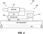
- the clutch mechanism 213 can be an over-running clutch 213 connected between the shaft 201 and the rotor 205.
- the over-running clutch can be configured to allow torque to be applied in only one direction such that the rotor 205 can drive the shaft 201, but shaft 201 cannot drive the rotor 205 (e.g., so that when the electrical machine 203 is not in use, the fuel powered engine cannot drive the electrical machine 203 to act as a generator).
- Any suitable over running clutch as appreciated by those having ordinary skill in the art, in view of this disclosure, is contemplate herein.
- the over running clutch 213 can directly connect between the shaft 201 and the rotor 205, e.g., as shown.
- the clutch mechanism 313 can be a face clutch mechanism 313 configured to slidably actuate (e.g., axially along the shaft 301) a face clutch member 315 that rotates with the shaft 301 to engage the rotor 305 in the first state and to disengage the rotor 305 in the second state to mechanically disconnect the rotor 305 from the shaft 301.
- the rotor 305 can include one or more rotor splines 317 configured to engage with one or more face splines 319 of the face clutch member 315 in the first state (e.g., as shown).
- the face clutch member 315 can be splined to the shaft 301 via one or more shaft splines 321 in connection with one or more axial splines 323 of the face clutch member 315.
- the face clutch mechanism 313 can include a biasing member 325 (e.g., biased in a downward direction as shown) configured to bias the face clutch member 315 (e.g., using a ramped face as shown to provide a camming action) toward the first state (e.g., in engagement with the rotor 305).
- the face clutch member 315 can be actuated by any suitable actuator connected thereto to pull the face clutch member 315 against the bias of the biasing member 325 (e.g., to pull to the right as shown). Any other suitable face clutch assembly and/or components therefor are contemplated herein.
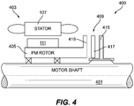
- the clutch mechanism 413 can be a friction clutch mechanism 413 having an actuator 415 and a friction member 417 (e.g., an elastic material disk).
- the actuator 415 can connect to the shaft 401 (e.g., via a spline connection) to rotate with the shaft 401 and to slide axially on the shaft 401.
- the friction member 417 can be configured to be pushed by the actuator 415 (e.g., to the left as shown) to contact a rotor face 419 (e.g., an end portion of the rotor 405 that is wider radially) to provide a frictional mechanical connection between the shaft 401 and the rotor 405 in the first state and to not push on the friction member 417 in the second state to mechanically disconnect the shaft 401 and the rotor 405 in the second state.
- Any suitable actuator and/or frictional member is contemplated herein as appreciated by those having ordinary skill in the art in view of this disclosure.
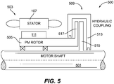
- the clutch mechanism 513 can be a hydraulic coupling 513 disposed around a rotor fan 517 and a shaft fan 515.
- the hydraulic coupling 513 can be configured to be sealed to the rotor 505 and the shaft 501 to retain a liquid (e.g., hydraulic fluid) therein when in a flooded state.
- the rotor fan 517 and the shaft fan 515 can be configured to be fluidly coupled in the flooded state (where liquid fills the cavity defined by the hydraulic coupling) such that the rotor fan 517 drives the shaft fan 515 (and thus drives the shaft 501).
- the rotor fan 517 and the shaft fan 515 can be configured to be fluidly decoupled in a drained state (e.g., when sufficient liquid, e.g., all, is drained from the coupling, e.g., and the couple is filled with air or vacuum).
- a drained state e.g., when sufficient liquid, e.g., all, is drained from the coupling, e.g., and the couple is filled with air or vacuum.
- Any suitable fluid connections, pumps, and/or fluid sources to selectively fill and drain the hydraulic coupling 513 are contemplated herein. Any other suitable design and/or components for the hydraulic coupling 513 as appreciated by those having ordinary skill in the art in view of this disclosure is contemplated herein.
- certain embodiments can include one or more bearings 135 disposed between the rotor 105, 205, 305, 405, 505 and the shaft 101, 201, 301, 401, 501 to allow the shaft to rotate relative to the rotor in the second state.
- Certain embodiments can include a fuel powered engine 137 (e.g., fossil fuel powered, e.g., a turbomachine) operatively connected to the shaft to drive the shaft. While certain embodiments of mechanical disconnection systems are disclosed above, any suitable mechanical disconnection system as appreciated by those having ordinary skill in the art in view of this disclosure is contemplated herein.
- a method can include mechanically disconnecting a rotor of an electrical machine from a shaft when an engine is driving the shaft.
- the method can include mechanically disconnecting the rotor of the electrical machine includes releasing a clutch mechanism. Any other suitable methods and/or portion thereof are contemplated herein.
- a hybrid drive system 600 can include a shaft 601, an electrical machine 603 having a stator 107, and a rotor 605 attached to the shaft 601 to rotate with the shaft 601 relative to the stator 107.
- the system 600 can include a rotor electromagnetic property modifying system 609 configured to modify an electromagnetic property of the rotor 605 to cause the rotor 605 and the stator 107 to be at least partially electromagnetically inactivated (e.g., either at least partially decoupled or caused to internally cancel output).
- the rotor electromagnetic property modifying system 109 can include a pole modification device (e.g., clocking mechanism 615) configured to modify one or more magnetic poles (e.g., change the location of relative to one or more other poles), e.g., 611N, 611S, 613N, 613S of the rotor 605 to at least partially electromagnetically inactivate the electrical machine 603.
- a pole modification device e.g., clocking mechanism 615
- modify one or more magnetic poles e.g., change the location of relative to one or more other poles
- 611N, 611S, 613N, 613S of the rotor 605 e.g., 611N, 611S, 613N, 613S of the rotor 605 to at least partially electromagnetically inactivate the electrical machine 603.
- the rotor 605 can be a permanent magnet rotor, as shown.
- the rotor 605 can include a first portion 605a, and a second portion 605b rotatable relative to the first portion 605a.
- the rotor 605 can include plurality of first permanent magnet poles 611N, 611S disposed on the first portion 605a and a plurality of second permanent magnet poles 613N, 613S disposed on the second portion 605b.
- the system 609 can include a clocking mechanism 615 configured to rotate one or both of the first portion 605a and the second portion 605b to change a relative position between the first poles 611N, 611S of the first portion 605a and the second poles 613N, 613S of the second portion 605b to at least partially electromagnetically inactivate the electrical machine 603.
- the clocking mechanism 615 can include any suitable actuator (e.g., an electric motor) and/or component(s) configured to connect to both portions 605a, 605b and to selectively allow rotatable motion therebetween.
- the actuator can include an electric motor that is controlled in any suitable manner (e.g., by a controller as a function of electrical output from the stator 107).
- the clocking mechanism 615 can be a biased coaxial bearing that is configured to be biased to the misaligned position, and having a releasable mechanism to allow rotation to the misaligned position. Any suitable structure and/or component(s) are contemplated herein.
- the clocking mechanism 615 can be configured to move the plurality of poles from an aligned state (e.g., as shown in Fig. 6 ) to a misaligned state to at least partially electromagnetically inactivate the electrical machine 603.
- the first poles 611N, 611S and the second poles 613N, 613S can include circumferentially alternating north poles 611N, 613N and south poles 611S, 613S.
- the aligned state can be defined by each north pole 611N of the first poles 611N, 611S aligning with each north pole 613N of the second poles 613N, 613S, and each south pole 61S of the first poles 611N, 611S aligning with the each south pole 613S of the second poles 613N, 613S.
- the misaligned state can be defined by opposite pole alignment such that north poles 611N, 613N of each portion 605a, 605b align with south poles 613S, 611S of the other portion 605b, 605a.
- the aligned state can correspond to an activated state
- the misaligned state can correspond to an inactivated state where rotor 605 rotation does not cause output from the stator 107 and such that input to the stator 107 does not cause rotor 105 rotation.
- Any other suitable aligned and misaligned states to prevent output from the stator 107 due to rotation of the rotor 605 and/or to prevent driving the rotor 605 with input to the stator 107 is contemplated herein.
- misaligning poles can prevent production of electrical output by creating two opposite outputs in the stator 107, thereby cancelling out electrical production from the stator 107.
- Such embodiments may have no mechanical disconnect, and may still provide a resistance to an engine 137 driving shaft 601, for example.
- a rotor 605, e.g., as described above, for an electrical machine can include a first portion 605a (e.g., a first half) and a second portion 605b (e.g., a second half) configured to connect to a shaft 601 and to rotate relative to each other on the shaft 601.
- At least one clocking mechanism 615 e.g., as described above, can be defined by or connected to the first portion and the second portion and configured to move the first portion and second portion relative to each other to modify an electromagnetic property of the rotor.
- the rotor 605 can include any other suitable components, e.g., as appreciated by those having ordinary skill in the art in accordance with this disclosure (e.g., more than two portions 605a, 605b). While embodiments are described above, any suitable electromagnetic inactivation (e.g., preventing generation or output of electrical current from the stator due to rotation of the rotor, and/or preventing rotor motion due to input current to the stator) is contemplated herein as appreciated by those having ordinary skill in the art in view of this disclosure.
- any suitable electromagnetic inactivation e.g., preventing generation or output of electrical current from the stator due to rotation of the rotor, and/or preventing rotor motion due to input current to the stator
- a method can include modifying an electromagnetic property of a permanent magnet rotor of an electrical machine to at least partially electromagnetically inactivate an electrical machine having a rotor attached to a rotating shaft and a stator without stopping rotation of the rotor.
- Modifying the electromagnetic property can include rotating at least a first portion of the rotor relative to a second portion of the rotor.
- modifying the electromagnetic property can include modifying magnetic pole alignment of one or more permanent magnetic poles of the rotor. Any other suitable methods and/or portions thereof are contemplated herein.
- a hybrid drive system 700, 800 can include a shaft 701, 801 and an electrical machine 703, 803 having a stator 107 and a rotor 705, 805 attached to the shaft 701, 801 to rotate with the shaft 701, 801 relative to the stator 107.
- the system 700, 800 can include an electromagnetic disconnect system 709, 809 configured to modify a position of the rotor 705, 805 to cause the rotor 705, 805 and the stator 107 to be at least partially electromagnetically decoupled.
- the rotor 705, 805 can include a permanent magnet 711, 811 (e.g., one or more), for example. Any other suitable type of magnet (e.g., an electromagnet) is contemplated herein.
- the electromagnetic disconnect system 709, 809 can be configured to move the rotor 705, 805 relative (e.g., axially) to the stator 107 to at least partially (e.g., fully) electromagnetically decouple the rotor 705, 805 and the stator 107.
- the electromagnetic disconnect system 709, 809 can be configured to move at least a portion of the rotor 705, 805 axially along the shaft 701, 801, for example.
- the electromagnetic disconnect system 709, 809 can include at least one hydraulic actuator assembly 713, 813 configured to selectively move at least a portion of the rotor 705, 805 axially along the shaft 701, 801 to at least partially electromagnetically decouple the rotor 705, 805 and the stator 107.
- the rotor 705, 805 can include a first portion 705a, 805a (e.g., a first half) and a second portion 705b, 805b (e.g., second half) configured to move relative to each other between an electromagnetically coupled position (e.g., as shown in Figs. 7 and 8 ) and an at least partially electromagnetically decoupled position (e.g., where first portion 705a, 805a is separated from second portion 705b, 805b).
- an electromagnetically coupled position e.g., as shown in Figs. 7 and 8
- an at least partially electromagnetically decoupled position e.g., where first portion 705a, 805a is separated
- the first portion 705a and the second portion 705b can define at least one hydraulic cavity 715 of the at least one hydraulic actuator assembly 713.
- the at least one hydraulic cavity 715 can be a single annular cavity, for example.
- each of the first portion 705a and the second portion 705b can be sealed to each other and to the shaft 701 with one or more seals 717 as shown.
- each of the first portion 705a and the second portion 705b can include a long leg 719a, 719b and/or a short leg 721a, 721b forming at least part of the hydraulic actuator assembly 713.
- the short legs 721a, 721b may be dimensioned to leave a gap in the electromagnetically coupled state to always have a hydraulic pathway to the at least one hydraulic cavity 715, e.g., as described below.
- the long legs 719a, 719b can be sealed to each other with at least one seal 717.
- the first portion 705a, 805a and the second portion 705b, 805b can be slidably splined to the shaft 701, 801 via one or more mating splines 723, 823 on the shaft 701, 801 and one or more rotor splines 725a, 825a, 725b, 825b.
- the at least one cavity 715 can be in fluid communication with a shaft cavity 727 through a shaft hole 729 to provide hydraulic pressure to the at least one cavity 715 through the shaft 701.
- the system as shown in Fig. 8 and further described below can include a similar hydraulic pathway through the shaft 801 as shown. Any other suitable hydraulic system and/or pathway is contemplated herein.
- the system 700 can include one or more backstops 731 configured to limit motion of the rotor 705 and/or portions 705a, 705b thereof, e.g., to prevent separation of the first portion 705a and the second portion 705b in the at least partially electromagnetically decoupled position.
- backstops 731 can stop further separation of the rotor portions 705a, 705b before long legs 719a, 719b move out of contact to maintain a seal.
- the at least one hydraulic actuator assembly 809 can include at least one nested piston assembly comprising a cylinder 833 and a piston 835 in a sealed sliding connection within the cylinder 833.
- the piston 835 and the cylinder 833 can define a hydraulic cavity 837 as shown (e.g., in fluid communication with a shaft cavity 827 through shaft opening 829, similar to the embodiment of Fig. 7 as described above).
- the piston 835 and the cylinder 833 can be configured to move relative to each other to move the first portion 805a and the second portion 805b relative to each other.
- the cylinder 833 can be connected to the second portion 805b and the piston 835 can be connected to or at least be in contact with the first portion 805a to push the portions apart when expanded.
- the at least one hydraulic actuator assembly 809 can include a plurality of hydraulic actuator assemblies 809 disposed circumferentially around at least one of the first portion 805a and/or the second portion 805b of the rotor 805 to provide multiple actuation points.
- one or more mirrored actuators (a mirror image of that shown Fig. 8 ) can be connected to provide opposing actuation when desired to provide push actuation in both directions to allow the portions 805a, 805b to be both separated and pushed back together. Any suitable assembly and/or hydraulic components are contemplated herein.
- a rotor 705, 805 for an electrical machine can include a first portion and a second portion configured to slidably connect to a shaft and to move relative to each other on the shaft.
- the rotor can include at least one hydraulic actuator assembly at least partially defined by or connected to the first portion and the second portion and configured to move the first portion and second portion between an electromagnetically coupled position and an at least partially electromagnetically decoupled position on the shaft.
- the first portion 705a and the second portion 705b can define at least one hydraulic cavity of the at least one hydraulic actuator assembly.
- Embodiments, e.g., as disclosed in Figs. 7 and 8 can remove the magnet from the inside of an electrical machine thereby at least partially, if not fully, decoupling the rotor and the stator for example.
- a method can include at least partially electromagnetically decoupling a rotor attached to a rotating shaft from a stator of an electrical machine without stopping rotation of the rotor. At least partially electromagnetically decoupling can include axially moving at least a portion of the rotor relative to the stator.
- axially moving at least a portion of the rotor relative to the stator can include actuating a hydraulic actuator to move at least a portion of the rotor relative to the stator.
- Axially moving at least a portion of the rotor relative to the stator can include moving a first portion of the rotor and a second portion of the rotor apart from each other to at least partially electromagnetically decouple the first portion and the second portion from the stator
- Certain embodiments disclosed hereinabove include systems configured to mechanically or otherwise disconnect an electrically driven motor from a fuel driven motor driveline, e.g., in the event of a system failure. Embodiments allow a fossil fuel driven motor to continue to provide propulsion without the electrically driven motor acting as a generator, for example.
- any numerical values disclosed herein can be exact values or can be values within a range. Further, any terms of approximation (e.g., “about”, “approximately”, “around”) used in this disclosure can mean the stated value within a range. For example, in certain embodiments, the range can be within (plus or minus) 20%, or within 10%, or within 5%, or within 2%, or within any other suitable percentage or number as appreciated by those having ordinary skill in the art (e.g., for known tolerance limits or error ranges).
Landscapes
- Engineering & Computer Science (AREA)
- Power Engineering (AREA)
- Connection Of Motors, Electrical Generators, Mechanical Devices, And The Like (AREA)
Abstract
Description
- This disclosure relates to electrical machine systems, e.g., systems for selectively disconnecting an electrical machine from a shaft.
- Hybrid propulsion concepts combine a fossil fuel driven motor with an electrically driven motor to drive a propeller or fan. Potential system failure modes precipitate the need to be able to disconnect the electrically driven motor from the shaft, e.g., when driven by a fuel powered engine.
- Such conventional methods and systems have generally been considered satisfactory for their intended purpose. However, there is still a need in the art for electrical machine disconnection systems. The present disclosure provides a solution for this need.
- In accordance with at least one aspect of this disclosure, a hybrid drive system can include a shaft, an electrical machine comprising a rotor and a stator, and a mechanical disconnect system connecting the rotor to the shaft. The mechanical disconnect system is configured to mechanically connect the rotor to the shaft in a first state and to mechanically disconnect the rotor from the shaft in a second state such that rotor does not drive the shaft or such that the rotor is not driven by the shaft.
- The rotor can be a permanent magnet rotor, for example. The mechanical disconnect system can include a clutch mechanism configured to mechanically connect and disconnect the rotor from the shaft.
- In certain embodiments, the mechanical disconnect system can include a gearing assembly configured to be engaged by the clutch mechanism in the first state and disengaged by the clutch mechanism in the second state to provide a geared connection between the rotor and the shaft in the first state. The gearing assembly can be configured to provide a freewheeling connection between the rotor and the shaft in the second state to mechanically disconnect the rotor from the shaft.
- The gearing assembly can include a carrier shaft configured to be engaged by the clutch mechanism to stop motion of the carrier shaft in the first state, and to be disengaged by the clutch mechanism to allow freewheeling in the second state. The carrier shaft can include a plurality of planet gears rotatably attached to the carrier shaft. The shaft can include a sun gear disposed thereon meshed with the planet gears. The rotor can include a ring gear disposed thereon meshed with the planet gears.
- In certain embodiments, the clutch mechanism can be an over-running clutch connected between the shaft and the rotor. The over-running clutch can be configured to allow torque to be applied in only one direction such that the rotor can drive the shaft, but shaft cannot drive the rotor.
- In certain embodiments, the clutch mechanism can be a face clutch mechanism configured to slidably actuate a face clutch member that rotates with the shaft to engage the rotor in the first state and to disengage the rotor in the second state to mechanically disconnect the rotor from the shaft. For example, the rotor can include one or more rotor splines configured to engage with one or more face splines of the face clutch member in the first state. The face clutch member can be splined to the shaft via one or more shaft splines in connection with one or more axial splines of the face clutch member.
- The face clutch mechanism can include a biasing member configured to bias the face clutch member toward the first position. The clutch mechanism can include a friction clutch mechanism having an actuator and a friction member. For example, the actuator can connect to the shaft to rotate with the shaft. The friction member can be configured to be pushed by the actuator to contact a rotor face to provide a frictional mechanical connection between the shaft and the rotor in the first state and to not push on the friction member in the second state to mechanically disconnect the shaft and the rotor in the second state.
- In certain embodiments, the clutch mechanism can include a hydraulic coupling disposed around a rotor fan and a shaft fan. The hydraulic coupling can be configured to be sealed to the rotor and the shaft to retain a liquid therein when in a flooded state. The rotor fan and the shaft fan can be configured to be fluidly coupled in the flooded state such that the rotor fan drives the shaft fan, and the rotor fan and the shaft fan can be configured to be fluidly decoupled in a drained state (e.g., when sufficient liquid, e.g., all is drained from the coupling, e.g., and the couple is filled with air or vacuum).
- Certain embodiments can include one or more bearings disposed between the rotor and the shaft to allow the shaft to rotate relative to the rotor in the second state. Certain embodiments can include a fuel powered engine operatively connected to the shaft to drive the shaft. While certain embodiments of mechanical disconnection systems are disclosed above, any suitable mechanical disconnection system as appreciated by those having ordinary skill in the art in view of this disclosure is contemplated herein.
- In accordance with at least one aspect of this disclosure, a method can include mechanically disconnecting a rotor of an electrical machine from a shaft when an engine is driving the shaft. The method can include mechanically disconnecting the rotor of the electrical machine includes releasing a clutch mechanism. Any other suitable methods and/or portion thereof are contemplated herein.
- In accordance with at least one aspect of this disclosure, a hybrid drive system can include a shaft, an electrical machine having a stator, and a rotor attached to the shaft to rotate with the shaft relative to the stator, and a rotor electromagnetic property modifying system configured to modify an electromagnetic property of the rotor to cause the rotor and the stator to be at least partially electromagnetically inactivated. For example, the rotor electromagnetic property modifying system can include a pole modification device configured to modify one or more magnetic poles of the rotor to at least partially electromagnetically inactivate the electrical machine.
- In certain embodiments, the rotor can be a permanent magnet rotor. The rotor can include a first portion and a second portion rotatable relative to the first portion. The rotor can include plurality of first permanent magnet poles disposed on the first portion and a plurality of second permanent magnet poles disposed on the second portion. For example, a clocking mechanism can be configured to rotate one or both of the first portion and the second portion to change a relative position between the first poles of the first portion and the second poles of the second portion to at least partially electromagnetically inactivate the electrical machine.
- The clocking mechanism can be configured to move the plurality of poles from an aligned state to a misaligned state to at least partially electromagnetically inactivate the electrical machine. For example, the first poles and the second poles can include circumferentially alternating north poles and south poles. The aligned state can be defined by each north pole of the first poles aligning with each north pole of the second poles, and each south pole of the first poles aligning with the each south pole of the second poles. The misaligned state can be defined by opposite pole alignment such that north poles of each portion align with south poles of each portion. The aligned state can correspond to an activated state, and the misaligned state can correspond to an inactivated state where rotor rotation does not cause output from the stator and such that input to the stator does not cause rotor rotation.
- In accordance with at least one aspect of this disclosure, a rotor, e.g., as described above, for an electrical machine can include a first portion and a second portion configured to connect to a shaft and to rotate relative to each other on the shaft. At least one clocking mechanism, e.g., as described above, can be defined by or connected to the first portion and the second portion and configured to move the first portion and second portion relative to each other to modify an electromagnetic property of the rotor. The rotor can include any other suitable component as disclosed herein. While embodiments are described above, any suitable electromagnetic inactivation (e.g., preventing generation or output of electrical current from the stator due to rotation of the rotor, and/or preventing rotor motion due to input current to the stator) is contemplated herein as appreciated by those having ordinary skill in the art in view of this disclosure.
- In accordance with at least one aspect of this disclosure, a method, can include modifying an electromagnetic property of a magnet rotor of an electrical machine to at least partially electromagnetically inactivate an electrical machine having a rotor attached to a rotating shaft and a stator without stopping rotation of the rotor. Modifying the electromagnetic property can include rotating at least a first portion of the rotor relative to a second portion of the rotor. In certain embodiments, modifying the electromagnetic property can include modifying magnetic pole alignment of one or more permanent magnetic poles of the rotor. Any other suitable methods and/or portions thereof are contemplated herein.
- In accordance with at least one aspect of this disclosure, a hybrid drive system can include a shaft and an electrical machine having a stator and a rotor attached to the shaft to rotate with the shaft relative to the stator. The system can include an electromagnetic disconnect system configured to modify a position of the rotor to cause the rotor and the stator to be at least partially electromagnetically decoupled. The rotor can include a permanent magnet, for example.
- The electromagnetic disconnect system can be configured to move the rotor relative to the stator to at least partially electromagnetically decouple the rotor and the stator. The electromagnetic disconnect system can be configured to move at least a portion of the rotor axially along the shaft.
- The electromagnetic disconnect system can include at least one hydraulic actuator assembly configured to selectively move at least a portion of the rotor axially along the shaft to at least partially electromagnetically decouple the rotor and the stator. For example, the rotor can include a first portion and a second portion configured to move relative to each other between an electromagnetically coupled position and an at least partially electromagnetically decoupled position.
- In certain embodiments, the first portion and the second portion can define at least one hydraulic cavity of the at least one hydraulic actuator assembly. In certain embodiments, the at least one hydraulic cavity is a single annular cavity.
- The first portion and the second portion can be slidably splined to the shaft via one or more mating splines on the shaft. The first portion and the second portion can be sealed to each other and to the shaft with one or more seals. In certain embodiments, the at least one cavity can be in fluid communication with a shaft cavity through a shaft hole to provide hydraulic pressure to the at least one cavity through the shaft. The system can include one or more backstops configured to limit motion and prevent separation of the first portion and the second portion in the at least partially electromagnetically decoupled position.
- In certain embodiments, the at least one hydraulic actuator assembly can include at least one nested piston assembly comprising a cylinder and a piston in a sealed sliding connection within the cylinder. The piston and the cylinder can be configured to move relative to each other to move the first portion and the second portion. The at least one hydraulic actuator assembly can include a plurality of hydraulic actuator assemblies disposed circumferentially around at least one of the first portion or the second portion of the rotor to provide multiple actuation points.
- In accordance with at least one aspect of this disclosure, a rotor for an electrical machine can include a first portion and a second portion configured to slidably connect to a shaft and to move relative to each other on the shaft. The rotor can include at least one hydraulic actuator assembly at least partially defined by or connected to the first portion and the second portion and configured to move the first portion and second portion between an electromagnetically coupled position and an at least partially electromagnetically decoupled position on the shaft. In certain embodiments, the first portion and the second portion can define at least one hydraulic cavity of the at least one hydraulic actuator assembly.
- In accordance with at least one aspect of this disclosure, a method can include at least partially electromagnetically decoupling a rotor attached to a rotating shaft from a stator of an electrical machine without stopping rotation of the rotor. At least partially electromagnetically decoupling can include axially moving at least a portion of the rotor relative to the stator.
- In certain embodiments, axially moving at least a portion of the rotor relative to the stator can include actuating a hydraulic actuator to move at least a portion of the rotor relative to the stator. Axially moving at least a portion of the rotor relative to the stator can include moving a first portion of the rotor and a second portion of the rotor apart from each other to at least partially electromagnetically decouple the first portion and the second portion from the stator.
- These and other features of the embodiments of the subject disclosure will become more readily apparent to those skilled in the art from the following detailed description taken in conjunction with the drawings.
- So that those skilled in the art to which the subject disclosure appertains will readily understand how to make and use the devices and methods of the subject disclosure without undue experimentation, embodiments thereof will be described in detail herein below with reference to certain figures, wherein:
-
Fig. 1 is a cross-sectional schematic view of an embodiment of a system in accordance with this disclosure, showing an embodiment of a mechanical disconnect system in accordance with this disclosure; -
Fig. 2 is a cross-sectional schematic view of an embodiment of a system in accordance with this disclosure, showing an embodiment of a mechanical disconnect system in accordance with this disclosure; -
Fig. 3 is a cross-sectional schematic view of an embodiment of a system in accordance with this disclosure, showing an embodiment of a mechanical disconnect system in accordance with this disclosure; -
Fig. 4 is a cross-sectional schematic view of an embodiment of a system in accordance with this disclosure, showing an embodiment of a mechanical disconnect system in accordance with this disclosure; -
Fig. 5 is a cross-sectional schematic view of an embodiment of a system in accordance with this disclosure, showing an embodiment of a mechanical disconnect system in accordance with this disclosure; -
Fig. 6 is a perspective schematic view of an embodiment of a rotor electromagnetic property modifying system in accordance with this disclosure, showing an embodiment of a rotor attached to a shaft; -
Fig. 7 is a cross-sectional schematic view of an embodiment of a system in accordance with this disclosure, showing an embodiment of an electromagnetic disconnect system in accordance with this disclosure; and -
Fig. 8 is a cross-sectional schematic view of an embodiment of a system in accordance with this disclosure, showing an embodiment of an electromagnetic disconnect system in accordance with this disclosure. - Reference will now be made to the drawings wherein like reference numerals identify similar structural features or aspects of the subject disclosure. For purposes of explanation and illustration, and not limitation, an illustrative view of an embodiment of a system in accordance with the disclosure is shown in
Fig. 1 and is designated generally byreference character 100. Other embodiments and/or aspects of this disclosure are shown inFigs. 2-8 . Certain embodiments described herein can be used cause an electrical machine to not produce electricity due to rotation of a rotor or to prevent force transfer to the rotor when current is applied to the stator. - In accordance with at least one aspect of this disclosure, referring to
Figs. 1-5 , ahybrid drive system shaft electrical machine rotor stator 107. Thesystem mechanical disconnect system rotor mechanical disconnect system rotor shaft rotor shaft rotor shaft rotor shaft - As shown the
rotor mechanical disconnect system clutch mechanism rotor shaft - As shown in
Fig. 1 , in certain embodiments, themechanical disconnect system 109 can include agearing assembly 109a configured to be engaged by theclutch mechanism 113 in the first state and disengaged by theclutch mechanism 113 in the second state to provide a geared connection between therotor 105 and theshaft 105 in the first state. Thegearing assembly 109a can be configured to provide a freewheeling connection between therotor 105 and theshaft 101 in the second state to mechanically disconnect therotor 105 from theshaft 101. - The gearing assembly can include a
carrier shaft 115 configured to be engaged by theclutch mechanism 113 to stop motion of thecarrier shaft 115 in the first state, and to be disengaged by theclutch mechanism 113 to allow freewheeling in the second state. Thecarrier shaft 115 can include a plurality ofplanet gears 117 rotatably attached (e.g., pinned to rotate on) to thecarrier shaft 115. Theshaft 101 can include asun gear 119 disposed thereon (e.g., integrally formed therewith) and meshed with the planet gears 117. Therotor 105 can include aring gear 121 disposed thereon (e.g., integrally formed therewith) and meshed with the planet gears 117. In the first state (e.g., where theelectrical machine 103 is driving the shaft 101), theclutch mechanism 113 can grip a portion of thecarrier shaft 115 to stop thecarrier shaft 115 relative to theshaft 101, which causes the planet gears 117 to be in a fixed position circumferentially relative to therotating shaft 101, which causes planet gears 117 to rotate about their own axis and to transfer torque from thering gear 121 to theshaft 101. In the second state (e.g., where the fuel powered engine drivesshaft 101 without the electrical machine 103), theclutch mechanism 113 can be released which causes thecarrier shaft 115 to freewheel such that planet gears 117 can rotate circumferentially around theshaft 101 and about their own axis which prevents transfer of torque from theshaft 101 to thering gear 121 and, thus, therotor 105. - Any suitable rotor to shaft gear ratio (e.g., 1:1, 1:1.5) is contemplated herein. Any other suitable gearing architecture and/or components to selectively prevent power transfer between the
rotor 105 and theshaft 101 are contemplated herein. - Referring to
Fig. 2 , in certain embodiments, theclutch mechanism 213 can be anover-running clutch 213 connected between theshaft 201 and therotor 205. The over-running clutch can be configured to allow torque to be applied in only one direction such that therotor 205 can drive theshaft 201, butshaft 201 cannot drive the rotor 205 (e.g., so that when theelectrical machine 203 is not in use, the fuel powered engine cannot drive theelectrical machine 203 to act as a generator). Any suitable over running clutch as appreciated by those having ordinary skill in the art, in view of this disclosure, is contemplate herein. For example, the over running clutch 213 can directly connect between theshaft 201 and therotor 205, e.g., as shown. - Referring to
Fig. 3 , in certain embodiments, theclutch mechanism 313 can be a faceclutch mechanism 313 configured to slidably actuate (e.g., axially along the shaft 301) a faceclutch member 315 that rotates with theshaft 301 to engage therotor 305 in the first state and to disengage therotor 305 in the second state to mechanically disconnect therotor 305 from theshaft 301. For example, therotor 305 can include one ormore rotor splines 317 configured to engage with one ormore face splines 319 of the faceclutch member 315 in the first state (e.g., as shown). The faceclutch member 315 can be splined to theshaft 301 via one ormore shaft splines 321 in connection with one or moreaxial splines 323 of the faceclutch member 315. - The face
clutch mechanism 313 can include a biasing member 325 (e.g., biased in a downward direction as shown) configured to bias the face clutch member 315 (e.g., using a ramped face as shown to provide a camming action) toward the first state (e.g., in engagement with the rotor 305). The faceclutch member 315 can be actuated by any suitable actuator connected thereto to pull the faceclutch member 315 against the bias of the biasing member 325 (e.g., to pull to the right as shown). Any other suitable face clutch assembly and/or components therefor are contemplated herein. - In certain embodiments, referring to
Fig. 4 , the clutch mechanism 413 can be a friction clutch mechanism 413 having anactuator 415 and a friction member 417 (e.g., an elastic material disk). For example, theactuator 415 can connect to the shaft 401 (e.g., via a spline connection) to rotate with theshaft 401 and to slide axially on theshaft 401. Thefriction member 417 can be configured to be pushed by the actuator 415 (e.g., to the left as shown) to contact a rotor face 419 (e.g., an end portion of therotor 405 that is wider radially) to provide a frictional mechanical connection between theshaft 401 and therotor 405 in the first state and to not push on thefriction member 417 in the second state to mechanically disconnect theshaft 401 and therotor 405 in the second state. Any suitable actuator and/or frictional member is contemplated herein as appreciated by those having ordinary skill in the art in view of this disclosure. - Referring to
Fig. 5 , in certain embodiments, theclutch mechanism 513 can be ahydraulic coupling 513 disposed around arotor fan 517 and ashaft fan 515. Thehydraulic coupling 513 can be configured to be sealed to therotor 505 and theshaft 501 to retain a liquid (e.g., hydraulic fluid) therein when in a flooded state. Therotor fan 517 and theshaft fan 515 can be configured to be fluidly coupled in the flooded state (where liquid fills the cavity defined by the hydraulic coupling) such that therotor fan 517 drives the shaft fan 515 (and thus drives the shaft 501). Therotor fan 517 and theshaft fan 515 can be configured to be fluidly decoupled in a drained state (e.g., when sufficient liquid, e.g., all, is drained from the coupling, e.g., and the couple is filled with air or vacuum). Any suitable fluid connections, pumps, and/or fluid sources to selectively fill and drain thehydraulic coupling 513 are contemplated herein. Any other suitable design and/or components for thehydraulic coupling 513 as appreciated by those having ordinary skill in the art in view of this disclosure is contemplated herein. - As shown in
Figs. 1-5 , certain embodiments can include one ormore bearings 135 disposed between therotor shaft - In accordance with at least one aspect of this disclosure, a method can include mechanically disconnecting a rotor of an electrical machine from a shaft when an engine is driving the shaft. The method can include mechanically disconnecting the rotor of the electrical machine includes releasing a clutch mechanism. Any other suitable methods and/or portion thereof are contemplated herein.
- In accordance with at least one aspect of this disclosure, referring to
Fig. 6 , ahybrid drive system 600 can include ashaft 601, anelectrical machine 603 having astator 107, and arotor 605 attached to theshaft 601 to rotate with theshaft 601 relative to thestator 107. Thesystem 600 can include a rotor electromagneticproperty modifying system 609 configured to modify an electromagnetic property of therotor 605 to cause therotor 605 and thestator 107 to be at least partially electromagnetically inactivated (e.g., either at least partially decoupled or caused to internally cancel output). For example, the rotor electromagneticproperty modifying system 109 can include a pole modification device (e.g., clocking mechanism 615) configured to modify one or more magnetic poles (e.g., change the location of relative to one or more other poles), e.g., 611N, 611S, 613N, 613S of therotor 605 to at least partially electromagnetically inactivate theelectrical machine 603. - In certain embodiments, the
rotor 605 can be a permanent magnet rotor, as shown. Therotor 605 can include afirst portion 605a, and asecond portion 605b rotatable relative to thefirst portion 605a. Therotor 605 can include plurality of firstpermanent magnet poles first portion 605a and a plurality of secondpermanent magnet poles second portion 605b. Thesystem 609 can include aclocking mechanism 615 configured to rotate one or both of thefirst portion 605a and thesecond portion 605b to change a relative position between thefirst poles first portion 605a and thesecond poles second portion 605b to at least partially electromagnetically inactivate theelectrical machine 603. Theclocking mechanism 615 can include any suitable actuator (e.g., an electric motor) and/or component(s) configured to connect to bothportions clocking mechanism 615 can be a biased coaxial bearing that is configured to be biased to the misaligned position, and having a releasable mechanism to allow rotation to the misaligned position. Any suitable structure and/or component(s) are contemplated herein. - The
clocking mechanism 615 can be configured to move the plurality of poles from an aligned state (e.g., as shown inFig. 6 ) to a misaligned state to at least partially electromagnetically inactivate theelectrical machine 603. For example, thefirst poles second poles north poles south poles north pole 611N of thefirst poles north pole 613N of thesecond poles first poles south pole 613S of thesecond poles north poles portion south poles other portion rotor 605 rotation does not cause output from thestator 107 and such that input to thestator 107 does not causerotor 105 rotation. Any other suitable aligned and misaligned states to prevent output from thestator 107 due to rotation of therotor 605 and/or to prevent driving therotor 605 with input to thestator 107 is contemplated herein. As appreciated by those having ordinary skill in the art in view of this disclosure, misaligning poles can prevent production of electrical output by creating two opposite outputs in thestator 107, thereby cancelling out electrical production from thestator 107. Such embodiments may have no mechanical disconnect, and may still provide a resistance to anengine 137 drivingshaft 601, for example. - In accordance with at least one aspect of this disclosure, a
rotor 605, e.g., as described above, for an electrical machine can include afirst portion 605a (e.g., a first half) and asecond portion 605b (e.g., a second half) configured to connect to ashaft 601 and to rotate relative to each other on theshaft 601. At least oneclocking mechanism 615, e.g., as described above, can be defined by or connected to the first portion and the second portion and configured to move the first portion and second portion relative to each other to modify an electromagnetic property of the rotor. Therotor 605 can include any other suitable components, e.g., as appreciated by those having ordinary skill in the art in accordance with this disclosure (e.g., more than twoportions - In accordance with at least one aspect of this disclosure, a method, can include modifying an electromagnetic property of a permanent magnet rotor of an electrical machine to at least partially electromagnetically inactivate an electrical machine having a rotor attached to a rotating shaft and a stator without stopping rotation of the rotor. Modifying the electromagnetic property can include rotating at least a first portion of the rotor relative to a second portion of the rotor. In certain embodiments, modifying the electromagnetic property can include modifying magnetic pole alignment of one or more permanent magnetic poles of the rotor. Any other suitable methods and/or portions thereof are contemplated herein.
- In accordance with at least one aspect of this disclosure, referring to
Figs. 7 and8 , a hybrid drive system 700, 800 can include ashaft 701, 801 and anelectrical machine stator 107 and arotor shaft 701, 801 to rotate with theshaft 701, 801 relative to thestator 107. The system 700, 800 can include anelectromagnetic disconnect system rotor rotor stator 107 to be at least partially electromagnetically decoupled. As shown, therotor permanent magnet 711, 811 (e.g., one or more), for example. Any other suitable type of magnet (e.g., an electromagnet) is contemplated herein. - The
electromagnetic disconnect system rotor stator 107 to at least partially (e.g., fully) electromagnetically decouple therotor stator 107. Theelectromagnetic disconnect system rotor shaft 701, 801, for example. - The
electromagnetic disconnect system hydraulic actuator assembly rotor shaft 701, 801 to at least partially electromagnetically decouple therotor stator 107. For example, therotor first portion second portion Figs. 7 and8 ) and an at least partially electromagnetically decoupled position (e.g., wherefirst portion second portion - Referring to
Fig. 7 , in certain embodiments, thefirst portion 705a and thesecond portion 705b can define at least onehydraulic cavity 715 of the at least onehydraulic actuator assembly 713. In certain embodiments, the at least onehydraulic cavity 715 can be a single annular cavity, for example. - The
first portion 705a and thesecond portion 705b can be sealed to each other and to theshaft 701 with one ormore seals 717 as shown. In certain embodiments, each of thefirst portion 705a and thesecond portion 705b can include along leg short leg 721a, 721b forming at least part of thehydraulic actuator assembly 713. As shown, theshort legs 721a, 721b may be dimensioned to leave a gap in the electromagnetically coupled state to always have a hydraulic pathway to the at least onehydraulic cavity 715, e.g., as described below. In certain embodiments, thelong legs seal 717. - Referring to both
Figs. 7 and8 , thefirst portion second portion shaft 701, 801 via one ormore mating splines shaft 701, 801 and one ormore rotor splines Fig. 7 , in certain embodiments, the at least onecavity 715 can be in fluid communication with ashaft cavity 727 through ashaft hole 729 to provide hydraulic pressure to the at least onecavity 715 through theshaft 701. The system as shown inFig. 8 and further described below can include a similar hydraulic pathway through the shaft 801 as shown. Any other suitable hydraulic system and/or pathway is contemplated herein. - As shown, the system 700 can include one or
more backstops 731 configured to limit motion of therotor 705 and/orportions first portion 705a and thesecond portion 705b in the at least partially electromagnetically decoupled position. For example, backstops 731 can stop further separation of therotor portions long legs - Referring to
Fig. 8 , in certain embodiments, the at least onehydraulic actuator assembly 809 can include at least one nested piston assembly comprising acylinder 833 and apiston 835 in a sealed sliding connection within thecylinder 833. Thepiston 835 and thecylinder 833 can define ahydraulic cavity 837 as shown (e.g., in fluid communication with ashaft cavity 827 throughshaft opening 829, similar to the embodiment ofFig. 7 as described above). Thepiston 835 and thecylinder 833 can be configured to move relative to each other to move thefirst portion 805a and thesecond portion 805b relative to each other. For example, thecylinder 833 can be connected to thesecond portion 805b and thepiston 835 can be connected to or at least be in contact with thefirst portion 805a to push the portions apart when expanded. - In certain embodiments, the at least one
hydraulic actuator assembly 809 can include a plurality ofhydraulic actuator assemblies 809 disposed circumferentially around at least one of thefirst portion 805a and/or thesecond portion 805b of therotor 805 to provide multiple actuation points. In certain embodiments, one or more mirrored actuators (a mirror image of that shownFig. 8 ) can be connected to provide opposing actuation when desired to provide push actuation in both directions to allow theportions - In accordance with at least one aspect of this disclosure, a
rotor Fig. 7 , thefirst portion 705a and thesecond portion 705b can define at least one hydraulic cavity of the at least one hydraulic actuator assembly. Embodiments, e.g., as disclosed inFigs. 7 and8 , can remove the magnet from the inside of an electrical machine thereby at least partially, if not fully, decoupling the rotor and the stator for example. - In accordance with at least one aspect of this disclosure, a method can include at least partially electromagnetically decoupling a rotor attached to a rotating shaft from a stator of an electrical machine without stopping rotation of the rotor. At least partially electromagnetically decoupling can include axially moving at least a portion of the rotor relative to the stator.
- In certain embodiments, axially moving at least a portion of the rotor relative to the stator can include actuating a hydraulic actuator to move at least a portion of the rotor relative to the stator. Axially moving at least a portion of the rotor relative to the stator can include moving a first portion of the rotor and a second portion of the rotor apart from each other to at least partially electromagnetically decouple the first portion and the second portion from the stator
- Traditional systems have no means to shut off the electrically driven motor from the driveline of a hybrid propulsion system. Certain embodiments disclosed hereinabove include systems configured to mechanically or otherwise disconnect an electrically driven motor from a fuel driven motor driveline, e.g., in the event of a system failure. Embodiments allow a fossil fuel driven motor to continue to provide propulsion without the electrically driven motor acting as a generator, for example.
- Those having ordinary skill in the art understand that any numerical values disclosed herein can be exact values or can be values within a range. Further, any terms of approximation (e.g., "about", "approximately", "around") used in this disclosure can mean the stated value within a range. For example, in certain embodiments, the range can be within (plus or minus) 20%, or within 10%, or within 5%, or within 2%, or within any other suitable percentage or number as appreciated by those having ordinary skill in the art (e.g., for known tolerance limits or error ranges).
- Any suitable combination(s) of any disclosed embodiments and/or any suitable portion(s) thereof are contemplated herein as appreciated by those having ordinary skill in the art.
- The embodiments of the present disclosure, as described above and shown in the drawings, provide for improvement in the art to which they pertain. While the subject disclosure includes reference to certain embodiments, those skilled in the art will readily appreciate that changes and/or modifications may be made thereto without departing from the scope of the invention as defined by the claims.
Claims (15)
- A hybrid drive system, comprising:a shaft (701); andan electrical machine (703), comprising:a stator (107); anda rotor (705) attached to the shaft to rotate with the shaft relative to the stator; andan electromagnetic disconnect system (709) configured to modify a position of the rotor to cause the rotor and the stator to be at least partially electromagnetically decoupled.
- The system of claim 1, wherein the rotor includes a permanent magnet (711).
- The system of claim 1 or 2, wherein the electromagnetic disconnect system is configured to move the rotor relative to the stator to at least partially electromagnetically decouple the rotor and the stator, and preferably wherein the electromagnetic disconnect system is configured to move at least a portion of the rotor axially along the shaft.
- The system of claim 3, wherein the electromagnetic disconnect system can include at least one hydraulic actuator assembly (713) configured to selectively move at least a portion of the rotor axially along the shaft to at least partially electromagnetically decouple the rotor and the stator.
- The system of claim45, wherein the rotor includes a first portion (705a) and a second portion (705b) configured to move relative to each other between an electromagnetically coupled position and an at least partially electromagnetically decoupled position.
- The system of claim 5, wherein the first portion and second portion define at least one hydraulic cavity (715) of the at least one hydraulic actuator assembly, and preferably wherein the at least one hydraulic cavity is a single annular cavity.
- The system of claim 6, wherein the first portion and the second portion are slidably splined to the shaft via one or more mating splines (723) on the shaft, and preferably wherein the first portion and the second portion are sealed to each other and to the shaft with one or more seals (717).
- The system of claim 6 or 7, wherein the at least one cavity is in fluid communication with a shaft cavity (827) through a shaft hole (829) to provide hydraulic pressure to the at least one cavity through the shaft.
- The system of any of claims 5 to 8, further comprising one or more backstops (731) configured to limit motion and prevent separation of the first portion and the second portion in the at least partially electromagnetically decoupled position.
- The system of any of claims 5 to 9, wherein the at least one hydraulic actuator assembly includes at least one nested piston assembly comprising a cylinder and a piston in a sealed sliding connection within the cylinder, the piston and the cylinder being configured to move relative to each other to move the first portion and the second portion, and wherein the at least one hydraulic actuator assembly includes a plurality of hydraulic actuator assemblies (809) disposed circumferentially around at least one of the first portion or the second portion of the rotor to provide multiple actuation points.
- A rotor for an electrical machine, comprising:a first portion and a second portion configured to slidably connect to a shaft and to move relative to each other on the shaft; andat least one hydraulic actuator assembly at least partially defined by or connected to the first portion and the second portion and configured to move the first portion and second portion between an electromagnetically coupled position and an at least partially electromagnetically decoupled position on the shaft.
- A method, comprising:
at least partially electromagnetically decoupling a rotor attached to a rotating shaft from a stator of an electrical machine without stopping rotation of the rotor. - The method of claim 12, wherein at least partially electromagnetically decoupling includes axially moving at least a portion of the rotor relative to the stator.
- The method of claim 13, wherein axially moving at least a portion of the rotor relative to the stator includes actuating a hydraulic actuator to move at least a portion of the rotor relative to the stator.
- The method of claim 14, wherein axially moving at least a portion of the rotor relative to the stator includes moving a first portion of the rotor and a second portion of the rotor apart from each other to at least partially electromagnetically decouple the first portion and the second portion from the stator.
Applications Claiming Priority (1)
| Application Number | Priority Date | Filing Date | Title |
|---|---|---|---|
| US16/242,729 US10879779B2 (en) | 2019-01-08 | 2019-01-08 | Electrical machine disconnection systems |
Publications (2)
| Publication Number | Publication Date |
|---|---|
| EP3681024A1 true EP3681024A1 (en) | 2020-07-15 |
| EP3681024B1 EP3681024B1 (en) | 2023-08-23 |
Family
ID=68581654
Family Applications (1)
| Application Number | Title | Priority Date | Filing Date |
|---|---|---|---|
| EP19209259.1A Active EP3681024B1 (en) | 2019-01-08 | 2019-11-14 | Electrical machine disconnection systems |
Country Status (2)
| Country | Link |
|---|---|
| US (1) | US10879779B2 (en) |
| EP (1) | EP3681024B1 (en) |
Citations (2)
| Publication number | Priority date | Publication date | Assignee | Title |
|---|---|---|---|---|
| JP2007267453A (en) * | 2006-03-27 | 2007-10-11 | Honda Motor Co Ltd | Electric motor |
| JP2010213488A (en) * | 2009-03-11 | 2010-09-24 | Yaskawa Electric Corp | Permanent magnet type rotary electric machine |
Family Cites Families (14)
| Publication number | Priority date | Publication date | Assignee | Title |
|---|---|---|---|---|
| US4578609A (en) * | 1982-09-29 | 1986-03-25 | The Garrett Corporation | Permanent magnet dynamoelectric machine |
| US4642683A (en) * | 1985-05-06 | 1987-02-10 | Eastman Kodak Company | Digital image processing method for images with bimodal tone value distribution |
| US5821710A (en) * | 1996-09-30 | 1998-10-13 | Hitachi Metals, Ltd. | Brushless motor having permanent magnets |
| US7259492B2 (en) * | 2001-09-27 | 2007-08-21 | Tai-Her Yang | Rotor axial activation modulation of electric machinery due to reverse torque |
| US20030164654A1 (en) * | 2002-02-25 | 2003-09-04 | Thaxton Edgar S. | Axially segmented permanent magnet synchronous machine with integrated magnetic bearings and active stator control of the axial degree-of-freedom |
| US7385332B2 (en) * | 2006-04-17 | 2008-06-10 | Hamilton Sundstrand Corporation | Permanent magnet dynamoelectric machine with axially displaceable permanent magnet rotor assembly |
| JP2009126404A (en) * | 2007-11-26 | 2009-06-11 | Hitachi Ltd | Hybrid vehicle |
| US8727271B2 (en) | 2008-01-11 | 2014-05-20 | Ival O. Salyer | Aircraft using turbo-electric hybrid propulsion system |
| US7804263B2 (en) * | 2008-02-21 | 2010-09-28 | Hamilton Sundstrand Corporation | Control system for a controllable permanent magnet machine |
| WO2013004595A1 (en) | 2011-07-07 | 2013-01-10 | Kasi Technologies Ab | Hybrid system comprising a supercharging system and method for operation |
| WO2014109006A1 (en) * | 2013-01-08 | 2014-07-17 | 株式会社安川電機 | Rotary electric machine |
| US9920689B2 (en) | 2013-03-15 | 2018-03-20 | Indiana University Research And Technology Corporation | Hybrid wave rotor propulsion system |
| US9193451B2 (en) | 2013-04-22 | 2015-11-24 | Ival O. Salyer | Aircraft using turbo-electric hybrid propulsion system for multi-mode operation |
| US10710449B2 (en) | 2016-07-15 | 2020-07-14 | GM Global Technology Operations LLC | Hybrid drivetrain |
-
2019
- 2019-01-08 US US16/242,729 patent/US10879779B2/en active Active
- 2019-11-14 EP EP19209259.1A patent/EP3681024B1/en active Active
Patent Citations (2)
| Publication number | Priority date | Publication date | Assignee | Title |
|---|---|---|---|---|
| JP2007267453A (en) * | 2006-03-27 | 2007-10-11 | Honda Motor Co Ltd | Electric motor |
| JP2010213488A (en) * | 2009-03-11 | 2010-09-24 | Yaskawa Electric Corp | Permanent magnet type rotary electric machine |
Also Published As
| Publication number | Publication date |
|---|---|
| US20200220442A1 (en) | 2020-07-09 |
| EP3681024B1 (en) | 2023-08-23 |
| US10879779B2 (en) | 2020-12-29 |
Similar Documents
| Publication | Publication Date | Title |
|---|---|---|
| CN114110122B (en) | a differential system | |
| EP3681018B1 (en) | Electrical machine disconnection systems | |
| EP3681019A1 (en) | Electrical machine disconnection systems | |
| US4808869A (en) | Integral magnetic torque limiting coupling/motor | |
| US6308794B1 (en) | Parallel hybrid drive for a motor vehicle having a clutch which is integrated in the electrical machine, and an associated electric motor unit | |
| US7086515B2 (en) | Clutch and synchronizer having permanent magnet actuators | |
| EP3319212B1 (en) | Electrical machine | |
| EP0238659A1 (en) | Quick disconnect mechanism | |
| EP1446566A1 (en) | Off loading clutch for gas turbine engine starting | |
| US11996758B2 (en) | Generator coupling system | |
| US10605338B2 (en) | Variable-speed speed increaser | |
| US20180278102A1 (en) | Electrical machine | |
| CN105570341A (en) | Electromagnetic clutch | |
| US20040084979A1 (en) | Integrated motor and clutch assembly | |
| US20160134171A1 (en) | Resettable electro-mechanically actuated connection unit for generators | |
| CN104747620B (en) | Electromagnetic clutch | |
| EP3681024B1 (en) | Electrical machine disconnection systems | |
| US20240424879A1 (en) | Electric drive system and method for minimizing mechanical losses in an auxiliary electric drive system thereof | |
| CN115704459A (en) | Powertrain Components | |
| CN108599526B (en) | connect/disconnect device | |
| CN204921764U (en) | Electromalgnetic clutch | |
| EP4414268A1 (en) | Power system | |
| CN204610615U (en) | Magnetic clutch | |
| GB2592977A (en) | Generator accessory drive | |
| CN100534824C (en) | Integrated motor and clutch assembly |
Legal Events
| Date | Code | Title | Description |
|---|---|---|---|
| PUAI | Public reference made under article 153(3) epc to a published international application that has entered the european phase |
Free format text: ORIGINAL CODE: 0009012 |
|
| STAA | Information on the status of an ep patent application or granted ep patent |
Free format text: STATUS: THE APPLICATION HAS BEEN PUBLISHED |
|
| AK | Designated contracting states |
Kind code of ref document: A1 Designated state(s): AL AT BE BG CH CY CZ DE DK EE ES FI FR GB GR HR HU IE IS IT LI LT LU LV MC MK MT NL NO PL PT RO RS SE SI SK SM TR |
|
| AX | Request for extension of the european patent |
Extension state: BA ME |
|
| STAA | Information on the status of an ep patent application or granted ep patent |
Free format text: STATUS: REQUEST FOR EXAMINATION WAS MADE |
|
| 17P | Request for examination filed |
Effective date: 20210115 |
|
| RBV | Designated contracting states (corrected) |
Designated state(s): AL AT BE BG CH CY CZ DE DK EE ES FI FR GB GR HR HU IE IS IT LI LT LU LV MC MK MT NL NO PL PT RO RS SE SI SK SM TR |
|
| STAA | Information on the status of an ep patent application or granted ep patent |
Free format text: STATUS: EXAMINATION IS IN PROGRESS |
|
| 17Q | First examination report despatched |
Effective date: 20210316 |
|
| RIN1 | Information on inventor provided before grant (corrected) |
Inventor name: BEHLING, DAVID S. Inventor name: SPIERLING, TODD A. |
|
| GRAP | Despatch of communication of intention to grant a patent |
Free format text: ORIGINAL CODE: EPIDOSNIGR1 |
|
| STAA | Information on the status of an ep patent application or granted ep patent |
Free format text: STATUS: GRANT OF PATENT IS INTENDED |
|
| INTG | Intention to grant announced |
Effective date: 20230307 |
|
| GRAS | Grant fee paid |
Free format text: ORIGINAL CODE: EPIDOSNIGR3 |
|
| GRAA | (expected) grant |
Free format text: ORIGINAL CODE: 0009210 |
|
| STAA | Information on the status of an ep patent application or granted ep patent |
Free format text: STATUS: THE PATENT HAS BEEN GRANTED |
|
| AK | Designated contracting states |
Kind code of ref document: B1 Designated state(s): AL AT BE BG CH CY CZ DE DK EE ES FI FR GB GR HR HU IE IS IT LI LT LU LV MC MK MT NL NO PL PT RO RS SE SI SK SM TR |
|
| REG | Reference to a national code |
Ref country code: GB Ref legal event code: FG4D |
|
| REG | Reference to a national code |
Ref country code: CH Ref legal event code: EP |
|
| REG | Reference to a national code |
Ref country code: DE Ref legal event code: R096 Ref document number: 602019035495 Country of ref document: DE |
|
| REG | Reference to a national code |
Ref country code: IE Ref legal event code: FG4D |
|
| REG | Reference to a national code |
Ref country code: LT Ref legal event code: MG9D |
|
| REG | Reference to a national code |
Ref country code: NL Ref legal event code: MP Effective date: 20230823 |
|
| REG | Reference to a national code |
Ref country code: AT Ref legal event code: MK05 Ref document number: 1603734 Country of ref document: AT Kind code of ref document: T Effective date: 20230823 |
|
| PG25 | Lapsed in a contracting state [announced via postgrant information from national office to epo] |
Ref country code: GR Free format text: LAPSE BECAUSE OF FAILURE TO SUBMIT A TRANSLATION OF THE DESCRIPTION OR TO PAY THE FEE WITHIN THE PRESCRIBED TIME-LIMIT Effective date: 20231124 |
|
| PG25 | Lapsed in a contracting state [announced via postgrant information from national office to epo] |
Ref country code: IS Free format text: LAPSE BECAUSE OF FAILURE TO SUBMIT A TRANSLATION OF THE DESCRIPTION OR TO PAY THE FEE WITHIN THE PRESCRIBED TIME-LIMIT Effective date: 20231223 |
|
| PG25 | Lapsed in a contracting state [announced via postgrant information from national office to epo] |
Ref country code: SE Free format text: LAPSE BECAUSE OF FAILURE TO SUBMIT A TRANSLATION OF THE DESCRIPTION OR TO PAY THE FEE WITHIN THE PRESCRIBED TIME-LIMIT Effective date: 20230823 Ref country code: RS Free format text: LAPSE BECAUSE OF FAILURE TO SUBMIT A TRANSLATION OF THE DESCRIPTION OR TO PAY THE FEE WITHIN THE PRESCRIBED TIME-LIMIT Effective date: 20230823 Ref country code: PT Free format text: LAPSE BECAUSE OF FAILURE TO SUBMIT A TRANSLATION OF THE DESCRIPTION OR TO PAY THE FEE WITHIN THE PRESCRIBED TIME-LIMIT Effective date: 20231226 Ref country code: NO Free format text: LAPSE BECAUSE OF FAILURE TO SUBMIT A TRANSLATION OF THE DESCRIPTION OR TO PAY THE FEE WITHIN THE PRESCRIBED TIME-LIMIT Effective date: 20231123 Ref country code: NL Free format text: LAPSE BECAUSE OF FAILURE TO SUBMIT A TRANSLATION OF THE DESCRIPTION OR TO PAY THE FEE WITHIN THE PRESCRIBED TIME-LIMIT Effective date: 20230823 Ref country code: LV Free format text: LAPSE BECAUSE OF FAILURE TO SUBMIT A TRANSLATION OF THE DESCRIPTION OR TO PAY THE FEE WITHIN THE PRESCRIBED TIME-LIMIT Effective date: 20230823 Ref country code: LT Free format text: LAPSE BECAUSE OF FAILURE TO SUBMIT A TRANSLATION OF THE DESCRIPTION OR TO PAY THE FEE WITHIN THE PRESCRIBED TIME-LIMIT Effective date: 20230823 Ref country code: IS Free format text: LAPSE BECAUSE OF FAILURE TO SUBMIT A TRANSLATION OF THE DESCRIPTION OR TO PAY THE FEE WITHIN THE PRESCRIBED TIME-LIMIT Effective date: 20231223 Ref country code: HR Free format text: LAPSE BECAUSE OF FAILURE TO SUBMIT A TRANSLATION OF THE DESCRIPTION OR TO PAY THE FEE WITHIN THE PRESCRIBED TIME-LIMIT Effective date: 20230823 Ref country code: GR Free format text: LAPSE BECAUSE OF FAILURE TO SUBMIT A TRANSLATION OF THE DESCRIPTION OR TO PAY THE FEE WITHIN THE PRESCRIBED TIME-LIMIT Effective date: 20231124 Ref country code: FI Free format text: LAPSE BECAUSE OF FAILURE TO SUBMIT A TRANSLATION OF THE DESCRIPTION OR TO PAY THE FEE WITHIN THE PRESCRIBED TIME-LIMIT Effective date: 20230823 Ref country code: AT Free format text: LAPSE BECAUSE OF FAILURE TO SUBMIT A TRANSLATION OF THE DESCRIPTION OR TO PAY THE FEE WITHIN THE PRESCRIBED TIME-LIMIT Effective date: 20230823 |
|
| PG25 | Lapsed in a contracting state [announced via postgrant information from national office to epo] |
Ref country code: PL Free format text: LAPSE BECAUSE OF FAILURE TO SUBMIT A TRANSLATION OF THE DESCRIPTION OR TO PAY THE FEE WITHIN THE PRESCRIBED TIME-LIMIT Effective date: 20230823 |
|
| PG25 | Lapsed in a contracting state [announced via postgrant information from national office to epo] |
Ref country code: ES Free format text: LAPSE BECAUSE OF FAILURE TO SUBMIT A TRANSLATION OF THE DESCRIPTION OR TO PAY THE FEE WITHIN THE PRESCRIBED TIME-LIMIT Effective date: 20230823 |
|
| PG25 | Lapsed in a contracting state [announced via postgrant information from national office to epo] |
Ref country code: SM Free format text: LAPSE BECAUSE OF FAILURE TO SUBMIT A TRANSLATION OF THE DESCRIPTION OR TO PAY THE FEE WITHIN THE PRESCRIBED TIME-LIMIT Effective date: 20230823 Ref country code: RO Free format text: LAPSE BECAUSE OF FAILURE TO SUBMIT A TRANSLATION OF THE DESCRIPTION OR TO PAY THE FEE WITHIN THE PRESCRIBED TIME-LIMIT Effective date: 20230823 Ref country code: ES Free format text: LAPSE BECAUSE OF FAILURE TO SUBMIT A TRANSLATION OF THE DESCRIPTION OR TO PAY THE FEE WITHIN THE PRESCRIBED TIME-LIMIT Effective date: 20230823 Ref country code: EE Free format text: LAPSE BECAUSE OF FAILURE TO SUBMIT A TRANSLATION OF THE DESCRIPTION OR TO PAY THE FEE WITHIN THE PRESCRIBED TIME-LIMIT Effective date: 20230823 Ref country code: DK Free format text: LAPSE BECAUSE OF FAILURE TO SUBMIT A TRANSLATION OF THE DESCRIPTION OR TO PAY THE FEE WITHIN THE PRESCRIBED TIME-LIMIT Effective date: 20230823 Ref country code: CZ Free format text: LAPSE BECAUSE OF FAILURE TO SUBMIT A TRANSLATION OF THE DESCRIPTION OR TO PAY THE FEE WITHIN THE PRESCRIBED TIME-LIMIT Effective date: 20230823 Ref country code: SK Free format text: LAPSE BECAUSE OF FAILURE TO SUBMIT A TRANSLATION OF THE DESCRIPTION OR TO PAY THE FEE WITHIN THE PRESCRIBED TIME-LIMIT Effective date: 20230823 |
|
| REG | Reference to a national code |
Ref country code: DE Ref legal event code: R097 Ref document number: 602019035495 Country of ref document: DE |
|
| PG25 | Lapsed in a contracting state [announced via postgrant information from national office to epo] |
Ref country code: IT Free format text: LAPSE BECAUSE OF FAILURE TO SUBMIT A TRANSLATION OF THE DESCRIPTION OR TO PAY THE FEE WITHIN THE PRESCRIBED TIME-LIMIT Effective date: 20230823 |
|
| PLBE | No opposition filed within time limit |
Free format text: ORIGINAL CODE: 0009261 |
|
| STAA | Information on the status of an ep patent application or granted ep patent |
Free format text: STATUS: NO OPPOSITION FILED WITHIN TIME LIMIT |
|
| REG | Reference to a national code |
Ref country code: CH Ref legal event code: PL |
|
| PG25 | Lapsed in a contracting state [announced via postgrant information from national office to epo] |
Ref country code: MC Free format text: LAPSE BECAUSE OF FAILURE TO SUBMIT A TRANSLATION OF THE DESCRIPTION OR TO PAY THE FEE WITHIN THE PRESCRIBED TIME-LIMIT Effective date: 20230823 |
|
| PG25 | Lapsed in a contracting state [announced via postgrant information from national office to epo] |
Ref country code: LU Free format text: LAPSE BECAUSE OF NON-PAYMENT OF DUE FEES Effective date: 20231114 |
|
| PG25 | Lapsed in a contracting state [announced via postgrant information from national office to epo] |
Ref country code: CH Free format text: LAPSE BECAUSE OF NON-PAYMENT OF DUE FEES Effective date: 20231130 |
|
| 26N | No opposition filed |
Effective date: 20240524 |
|
| PG25 | Lapsed in a contracting state [announced via postgrant information from national office to epo] |
Ref country code: MC Free format text: LAPSE BECAUSE OF FAILURE TO SUBMIT A TRANSLATION OF THE DESCRIPTION OR TO PAY THE FEE WITHIN THE PRESCRIBED TIME-LIMIT Effective date: 20230823 Ref country code: LU Free format text: LAPSE BECAUSE OF NON-PAYMENT OF DUE FEES Effective date: 20231114 Ref country code: CH Free format text: LAPSE BECAUSE OF NON-PAYMENT OF DUE FEES Effective date: 20231130 Ref country code: SI Free format text: LAPSE BECAUSE OF FAILURE TO SUBMIT A TRANSLATION OF THE DESCRIPTION OR TO PAY THE FEE WITHIN THE PRESCRIBED TIME-LIMIT Effective date: 20230823 |
|
| REG | Reference to a national code |
Ref country code: BE Ref legal event code: MM Effective date: 20231130 |
|
| REG | Reference to a national code |
Ref country code: IE Ref legal event code: MM4A |
|
| PG25 | Lapsed in a contracting state [announced via postgrant information from national office to epo] |
Ref country code: IE Free format text: LAPSE BECAUSE OF NON-PAYMENT OF DUE FEES Effective date: 20231114 |
|
| PG25 | Lapsed in a contracting state [announced via postgrant information from national office to epo] |
Ref country code: BE Free format text: LAPSE BECAUSE OF NON-PAYMENT OF DUE FEES Effective date: 20231130 |
|
| PG25 | Lapsed in a contracting state [announced via postgrant information from national office to epo] |
Ref country code: IE Free format text: LAPSE BECAUSE OF NON-PAYMENT OF DUE FEES Effective date: 20231114 Ref country code: BE Free format text: LAPSE BECAUSE OF NON-PAYMENT OF DUE FEES Effective date: 20231130 |
|
| PG25 | Lapsed in a contracting state [announced via postgrant information from national office to epo] |
Ref country code: BG Free format text: LAPSE BECAUSE OF FAILURE TO SUBMIT A TRANSLATION OF THE DESCRIPTION OR TO PAY THE FEE WITHIN THE PRESCRIBED TIME-LIMIT Effective date: 20230823 |
|
| PG25 | Lapsed in a contracting state [announced via postgrant information from national office to epo] |
Ref country code: BG Free format text: LAPSE BECAUSE OF FAILURE TO SUBMIT A TRANSLATION OF THE DESCRIPTION OR TO PAY THE FEE WITHIN THE PRESCRIBED TIME-LIMIT Effective date: 20230823 |
|
| PG25 | Lapsed in a contracting state [announced via postgrant information from national office to epo] |
Ref country code: CY Free format text: LAPSE BECAUSE OF FAILURE TO SUBMIT A TRANSLATION OF THE DESCRIPTION OR TO PAY THE FEE WITHIN THE PRESCRIBED TIME-LIMIT; INVALID AB INITIO Effective date: 20191114 |
|
| PG25 | Lapsed in a contracting state [announced via postgrant information from national office to epo] |
Ref country code: HU Free format text: LAPSE BECAUSE OF FAILURE TO SUBMIT A TRANSLATION OF THE DESCRIPTION OR TO PAY THE FEE WITHIN THE PRESCRIBED TIME-LIMIT; INVALID AB INITIO Effective date: 20191114 |
|
| PG25 | Lapsed in a contracting state [announced via postgrant information from national office to epo] |
Ref country code: TR Free format text: LAPSE BECAUSE OF FAILURE TO SUBMIT A TRANSLATION OF THE DESCRIPTION OR TO PAY THE FEE WITHIN THE PRESCRIBED TIME-LIMIT Effective date: 20230823 |
|
| PGFP | Annual fee paid to national office [announced via postgrant information from national office to epo] |
Ref country code: DE Payment date: 20251022 Year of fee payment: 7 |
|
| PGFP | Annual fee paid to national office [announced via postgrant information from national office to epo] |
Ref country code: GB Payment date: 20251023 Year of fee payment: 7 |
|
| PGFP | Annual fee paid to national office [announced via postgrant information from national office to epo] |
Ref country code: FR Payment date: 20251022 Year of fee payment: 7 |
|
| P01 | Opt-out of the competence of the unified patent court (upc) registered |
Free format text: CASE NUMBER: UPC_APP_0018911_3681024/2025 Effective date: 20251222 |