EP3680990A1 - Connector housing and connector - Google Patents
Connector housing and connector Download PDFInfo
- Publication number
- EP3680990A1 EP3680990A1 EP18854399.5A EP18854399A EP3680990A1 EP 3680990 A1 EP3680990 A1 EP 3680990A1 EP 18854399 A EP18854399 A EP 18854399A EP 3680990 A1 EP3680990 A1 EP 3680990A1
- Authority
- EP
- European Patent Office
- Prior art keywords
- cover
- conductor exposed
- board
- housing body
- fore
- Prior art date
- Legal status (The legal status is an assumption and is not a legal conclusion. Google has not performed a legal analysis and makes no representation as to the accuracy of the status listed.)
- Granted
Links
Images






Classifications
-
- H—ELECTRICITY
- H01—ELECTRIC ELEMENTS
- H01R—ELECTRICALLY-CONDUCTIVE CONNECTIONS; STRUCTURAL ASSOCIATIONS OF A PLURALITY OF MUTUALLY-INSULATED ELECTRICAL CONNECTING ELEMENTS; COUPLING DEVICES; CURRENT COLLECTORS
- H01R13/00—Details of coupling devices of the kinds covered by groups H01R12/70 or H01R24/00 - H01R33/00
- H01R13/02—Contact members
- H01R13/025—Contact members formed by the conductors of a cable end
-
- H—ELECTRICITY
- H01—ELECTRIC ELEMENTS
- H01R—ELECTRICALLY-CONDUCTIVE CONNECTIONS; STRUCTURAL ASSOCIATIONS OF A PLURALITY OF MUTUALLY-INSULATED ELECTRICAL CONNECTING ELEMENTS; COUPLING DEVICES; CURRENT COLLECTORS
- H01R13/00—Details of coupling devices of the kinds covered by groups H01R12/70 or H01R24/00 - H01R33/00
- H01R13/58—Means for relieving strain on wire connection, e.g. cord grip, for avoiding loosening of connections between wires and terminals within a coupling device terminating a cable
- H01R13/582—Means for relieving strain on wire connection, e.g. cord grip, for avoiding loosening of connections between wires and terminals within a coupling device terminating a cable the cable being clamped between assembled parts of the housing
- H01R13/5829—Means for relieving strain on wire connection, e.g. cord grip, for avoiding loosening of connections between wires and terminals within a coupling device terminating a cable the cable being clamped between assembled parts of the housing the clamping part being flexibly or hingedly connected to the housing
-
- H—ELECTRICITY
- H01—ELECTRIC ELEMENTS
- H01R—ELECTRICALLY-CONDUCTIVE CONNECTIONS; STRUCTURAL ASSOCIATIONS OF A PLURALITY OF MUTUALLY-INSULATED ELECTRICAL CONNECTING ELEMENTS; COUPLING DEVICES; CURRENT COLLECTORS
- H01R11/00—Individual connecting elements providing two or more spaced connecting locations for conductive members which are, or may be, thereby interconnected, e.g. end pieces for wires or cables supported by the wire or cable and having means for facilitating electrical connection to some other wire, terminal, or conductive member, blocks of binding posts
- H01R11/11—End pieces or tapping pieces for wires, supported by the wire and for facilitating electrical connection to some other wire, terminal or conductive member
-
- H—ELECTRICITY
- H01—ELECTRIC ELEMENTS
- H01R—ELECTRICALLY-CONDUCTIVE CONNECTIONS; STRUCTURAL ASSOCIATIONS OF A PLURALITY OF MUTUALLY-INSULATED ELECTRICAL CONNECTING ELEMENTS; COUPLING DEVICES; CURRENT COLLECTORS
- H01R13/00—Details of coupling devices of the kinds covered by groups H01R12/70 or H01R24/00 - H01R33/00
- H01R13/46—Bases; Cases
- H01R13/50—Bases; Cases formed as an integral body
- H01R13/501—Bases; Cases formed as an integral body comprising an integral hinge or a frangible part
-
- H—ELECTRICITY
- H01—ELECTRIC ELEMENTS
- H01R—ELECTRICALLY-CONDUCTIVE CONNECTIONS; STRUCTURAL ASSOCIATIONS OF A PLURALITY OF MUTUALLY-INSULATED ELECTRICAL CONNECTING ELEMENTS; COUPLING DEVICES; CURRENT COLLECTORS
- H01R13/00—Details of coupling devices of the kinds covered by groups H01R12/70 or H01R24/00 - H01R33/00
- H01R13/46—Bases; Cases
- H01R13/502—Bases; Cases composed of different pieces
- H01R13/506—Bases; Cases composed of different pieces assembled by snap action of the parts
Definitions
- the present invention relates to a connector housing for configuring a connector in which a conductor exposed portion at a fore-end of a harness is directly used as an electric contact, and relates to a connector configured using the connector housing.
- a connector which uses a conductor exposed portion at a fore-end of a harness (electric wire) directly as an electric contact. Since this type of connector can omit a terminal fitting, the connector can be configured simply. Therefore, for example, the connector is used as a connector for connecting a power supply terminal of a bicycle hub dynamo and a lamp.
- a connector which includes a housing body (a first housing portion), a cover (a second housing portion), and a connection portion which connects the housing body and the cover.
- the connector that clamps the harness between the housing body and the cover by coupling the housing body and the cover in a manner of bending the connection portion by about 90 degrees is disclosed.
- the connecting portion serves as one end of the coupling between the housing body and the cover.
- a middle portion of the conductor exposed portion at the fore-end of the harness is bent into a U shape at a front end edge of the board to prevent the harness from coming out, and a part of the conductor exposed portion serves as an electric contact which is in conductive contact with an electric contact of a mating connector.
- Paten literature 1 Japanese Patent Laid-open No. 2016-41591
- the connector described in patent literature 1 has a structure that when a tensile force is applied to the harness, the force is mainly received by either the housing body or the cover. Therefore, when a strong tensile force acts, the coupling between the housing body and the cover tends to misalign or detach.
- the connecting portion serves as one end of the coupling between the housing body and the cover. Thus, for example, if the connection portion is damaged due to deterioration over time, an external force or the like, the cover may also fall off from the housing body.
- the present invention is completed in view of the above situations and aims to provide a connector housing with which integral coupling property of two members for clamping harness can be enhanced and the coupling is not prone to misalign or detach, and a connector which is configured using the connector housing.
- the connector housing includes: a board which supports a conductor exposed portion bent in a U shape at a fore-end of a harness when a direction in which a mating connector is fitted is set as the front, wherein the board has a front end edge where a U-shaped bent portion of the conductor exposed portion is arranged, a first plate surface on which a part of the conductor exposed portion closer to a base-end side than the U-shaped bent portion is arranged along a front-rear direction, and a second plate surface on which a part of the conductor exposed portion closer to a fore-end side than the U-shaped bent portion is arranged along the front-rear direction; a harness guide portion which is arranged on one plate surface of the first plate surface and the second plate surface and support the part on the fore-end side or the part on the base-end side of the conductor exposed portion which is arranged on the one plate surface, the part serving as an electric contact which is in conductive contact with an electric
- the conductor exposed portion supported by the harness guide portion on the one plate surface of the board can function as the electric contact in conductive contact with the electric contact of the mating connector.
- the harness can be clamped between the cover which is in surface matching with the other plate surface of the board and the board.
- the other plate surface is set as the first plate surface and the one plate surface is set as the second plate surface
- the U-shaped bent portion of the conductor exposed portion at the fore-end of the harness is arranged on the front end edge.
- the part of the conductor exposed portion closer to the base-end side than the U-shaped bent portion is arranged on the first plate surface (the other plate surface) along the front-rear direction.
- the part of the conductor exposed portion closer to the fore-end side than the U-shaped bent portion is arranged on the second plate surface (the one plate surface) along the front-rear direction.
- the part on the fore-end side of the conductor exposed portion can function as the electric contact which is in conductive contact with the electric contact of the mating connector.
- the other plate surface is set as the second plate surface and the one plate surface is set as the first plate surface
- the U-shaped bent portion of the conductor exposed portion at the fore-end of the harness is arranged on the front end edge.
- the part of the conductor exposed portion closer to the base-end side than the U-shaped bent portion is arranged on the first plate surface (the one plate surface) along the front-rear direction.
- the part of the conductor exposed portion closer to the fore-end side than the U-shaped bent portion is arranged on the second plate surface (the other plate surface) along the front-rear direction.
- the cover is coupled to the board, and the cover is brought into surface matching with the second plate surface (the other plate surface), and thereby the fore-end side of the conductor exposed portion can be clamped between the second plate surface (the other plate surface) of the board and the cover.
- the part on the base-end side of the conductor exposed portion can function as the electric contact which is in conductive contact with the electric contact of the mating connector.
- the cover when the cover is coupled to the board by the coupling part in this way, the front projecting piece of the cover is engaged with the front end of the board, and the rear projecting piece of the cover is engaged with the rear end of the board. Therefore, movement of the board in the front-rear direction can be restricted by the cover, and the integral coupling property between the cover and the board can be enhanced. In addition, even when an external force in the front-rear direction acts via the harness or the mating connector, the coupling between the board and the cover can be prevented from being misaligned or detached.
- the connector housing includes a box, wherein an insertion hole into which a insertion piece being strip-like of the mating connector is inserted is formed by enclosing four sides with a lower plate, an upper plate facing the lower plate, left and right plates connecting the lower plate and the upper plate, and an opening in a front surface serves as a receiving port of the insertion piece into the insertion hole, wherein the board is arranged as the lower plate of the box, the one plate surface of the board on which the harness guide portion is formed serves as an upper surface of the lower plate configuring an inner surface of the insertion hole, and the other plate surface of the board in surface matching with the cover to clamp the harness serves as a lower surface of the lower plate, and the front projecting piece of the cover is formed as a front frame portion which covers the front surface of the box when the cover is coupled to the box, and an opening for opening the receiving port at the front is arranged in the front frame portion.
- the insertion piece of the mating connector can be inserted into the insertion hole of the box from the receiving port which is open on the front surface of the box. Besides, the electric contact on the lower surface of the insertion piece being inserted can be brought into sliding contact with the conductor exposed portion (the electric contact) disposed on the harness guide portion on the upper surface of the lower plate (the board) of the box.
- the insertion piece of the mating connector can be inserted into the receiving port of the box through the opening of the front frame portion of the cover. Therefore, the front frame portion can be arranged in a size for covering the entire front end surface of the box, and the integral coupling property with the box can be further enhanced. Furthermore, since the front frame portion and the mating connector are fitted with each other, the cover is supplementarily supported by the mating connector. Thus, the cover can be reliably prevented from falling off the box.
- a notch where the U-shaped bent portion of the conductor exposed portion is housed is arranged at a front edge portion of the harness guide portion.
- the bending can be easily performed at a stable position without lateral displacement.
- the bent place of the conductor exposed portion can be housed inside the notch, a protrusion caused by the bending is not prone to occur at the front end of the board (the lower plate of the box), and the front frame portion of the cover is easily brought into close contact with to the front end surface of the box.
- the connector housing is provided that a through hole which penetrate from the one plate surface to the other plate surface of the board is arranged at a rear portion of the harness guide portion.
- the fore-end of the conductor exposed portion is hooked in the through hole arranged in the lower plate (the board), and the fore-end side of the conductor exposed portion can be arranged in the harness guide portion.
- the middle portion of the conductor exposed portion can be bent into a U shape with the front end edge of the lower plate (the board) as a bending fulcrum. Therefore, since the bending operation can be performed in a state that the fore-end of the conductor exposed portion is constrained by the through hole, the bending work can be performed particularly stably and easily.
- a position of the fore-end of the conductor exposed portion inside the box can be confirmed from the outside through the through hole regardless of whether or not the fore-end of the conductor exposed portion is hooked in the through hole arranged in the lower plate (the board). Therefore, precision of the position of the conductor exposed portion arranged in the harness guide portion or the bending position can be enhanced.
- a window through which the through hole can be visually recognized from the outside is arranged in the upper plate of the box.
- the hooked state of the conductor exposed portion to the through hole can be confirmed by watching through the window, and the bending work of conductor exposed portion or the like can be performed while the hooked state is confirmed.
- the box is arranged as a part of a housing body, and the cover is integrally connected to the housing body via a bendable hinge.
- the connector housing can be made of an integrally molded resin product.
- the cover can be coupled to the housing body in a state that the cover is aligned.
- a connector according to the present invention is configured to introduce the fore-end of the harness to the above connector housing, wherein the U-shaped bent portion of the conductor exposed portion at the fore-end of the harness is arranged at a front end edge of the board, the part of the conductor exposed portion closer to the fore-end side than the U-shaped bent portion is arranged on the first plate surface of the board along the front-rear direction, and the part of the conductor exposed portion closer to the base-end side than the U-shaped bent portion is arranged on the second plate surface of the board along the front-rear direction; the part on the fore-end side or the part on the base-end side of the conductor exposed portion is disposed in the harness guide portion which is arranged on one plate surface of the first plate surface and the second plate surface, and thereby the base-end side or the fore-end side of the conductor exposed portion is configured as an electric contact which is in conductive contact with an electric contact of the mating connector; the harness is clamped between the cover and the board by bringing
- the movement of the board in the front-rear direction can be restricted by the cover, and the integral coupling property between the cover and the board can be enhanced.
- the coupling between the board and the cover can be prevented from being misaligned or detached.
- a connector described here is useful as a two-wire type connector which is connected to a power supply terminal (a mating connector) of a hub dynamo of a bicycle, and can also be used widely as other general electrical connectors.
- a connector housing configuring the connector is configured by one component (an integrally molded product).
- a connector housing configuring the connector is configured by two components (separately molded products).
- the connector housing of the first embodiment of the present invention and a connector configured using the connector housing are described with reference to FIG. 1-FIG. 12 .
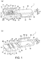
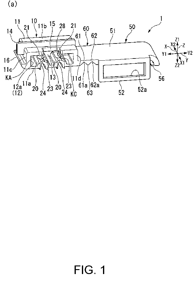
- FIG. 1 are perspective views showing a state before use of a connector housing 1 in the first embodiment of the present invention, where (a) is a perspective view viewed from the front, and (b) is a perspective view viewed from the rear with the top and the bottom turned upside down.
- FIG. 2 are diagrams showing a state before use of the connector housing 1, where (a) is a front view viewed from the front, and (b) is a rear view viewed from the rear with the top and the bottom turned upside down.
- FIG. 1 are perspective views showing a state before use of a connector housing 1 in the first embodiment of the present invention, where (a) is a perspective view viewed from the front, and (b) is a perspective view viewed from the rear with the top and the bottom turned upside down.
- FIG. 1 are perspective views showing a state before use of a connector housing 1 in the first embodiment of the present invention, where (a) is a perspective view viewed from the front, and (b) is a perspective view viewed from the rear with the top and
- FIG. 3 are illustration views of a method for assembling a connector 2 by using the connector housing 1, where (a) is a perspective view showing a state that conductor exposed portions Wa at fore-ends Wa1 of harnesses W are about to be inserted into a housing body 10 from the front, (b) is a perspective view showing a state that base-end sides of the harnesses W are bent and extended rearward, and (c) is a perspective view showing a state that a cover 50 is coupled to the housing body 10 and the connector 2 is completed.
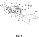
- FIG. 4 is a perspective view showing a state that a mating connector 200 is about to be fitted to the completed connector 2.
- the connector housing 1 of the first embodiment shown in FIG. 1 and FIG. 2 is a main component for configuring a two-wire connector connected to a power supply terminal (the mating connector) of a hub dynamo.
- the connector housing 1 is integrally molded by resin and includes the housing body 10, the cover 50, and a hinge 60 which connects the housing body 10 and the cover 50.
- FIG. 1(a) is a diagram viewed from diagonally front
- FIG. 1(b) is a diagram viewed from diagonally rear.
- a direction where the housing body 10 and the cover 50 are coupled is referred to as an up-down direction Z, and in the coupled state, a direction where the housing body 10 is positioned is referred to as the up (an upper side) Z1, and a direction where the cover 50 is positioned is referred to as the down (a lower side) Z2.
- the connector housing 1 configures a connector without using a terminal fitting.
- the harnesses W extend rearward from the connector 2. Therefore, when viewed from the harnesses W extending rearward from the connector 2, the fore-ends of the harnesses W are introduced from the rear toward the front with respect to the connector 2. For example, even if the fore-ends of the harnesses W are introduced from the front toward the rear in the middle of the assembly as shown in FIG. 3(a) , when the connector 2 is finally completed, as shown in FIG. 3(c) , the fore-ends of the harnesses W are introduced from the rear to the front.
- the housing body 10 of the connector housing 1 has a box 11 being a rectangular shape in which the dimension in the up-down direction is smaller than the dimension in the left-right direction when viewed from the front.
- the box 11 is configured by surrounding four sides with a lower plate 11a, an upper plate 11b facing the lower plate 11a, and a left plate 11c and a right plate 11d that connect the lower plate 11a and the upper plate 11b.
- the inside of the box 11 is configured as an insertion hole 12 into which a strip-like insertion piece 201 (see FIG. 4 ) of the mating connector 200 is inserted.
- a front surface of the insertion hole 12 is opened as a receiving port 12a for receiving the insertion piece 201 of the mating connector 200.
- a depth portion of the insertion hole 12 of the box 11 is blocked by a rear wall 13.
- an outer peripheral surface of an upper half portion and an outer peripheral surface of the upper plate 11b are integrated so as to cover a plate-like rib 14 having a U shape in a front view.
- an engagement claw 16 (a coupling part) which protrudes toward the left Y1 is arranged.
- the cover 50 is connected to the outer side of a right end portion of the lower plate 11a of the box 11 via the hinge 60. Accordingly, the cover 50 before assembly is arranged on the right side Y2 of the housing body 10.
- the harnesses W are obtained by covering harness core wires (conductive wires) Wa with insulation coatings Wb.
- the harness core wire Wa may be composed of a large number of strands or be composed of a single strand (a single wire).
- the insulation coatings Wb within a predetermined length of the fore-ends of the harnesses W are peeled off to expose the harness core wires Wa.
- the exposed core wires Wa at the fore-ends are referred to as the conductor exposed portions Wa and are denoted by the same symbol as the conductors Wa.
- the lower plate 11a of the box 11 is configured as a board which supports the conductor exposed portions Wa bent in a U shape at the fore-ends of the harnesses W.
- the lower plate 11a serving as the board has parts which function as a first plate surface, a front end edge, and a second plate surface described below, respectively. That is, the lower plate 11a serving as the board has a front end edge KC where U-shaped bent portions of the conductor exposed portions Wa are disposed.
- the lower plate 11a has a lower surface KB serving as the first plate surface where parts of the conductor exposed portions Wa closer to the base-end sides than the U-shaped bent portions are disposed along the front-rear direction.
- the lower plate 11a has an upper surface KA (an inner bottom surface of the insertion hole 12) serving as the second plate surface where parts of the conductor exposed portions Wa closer to the fore-end sides than the U-shaped bent portions are disposed along the front-rear direction.
- KA an inner bottom surface of the insertion hole 12
- harness holding projection portions 20 On the upper surface KA (corresponding to one plate surface) of the lower plate 11a of the housing body 10, along the front-rear direction, two harness holding projection portions 20 having a semi-circular cross section are arranged in parallel and spaced from each other in the left-right direction Y.
- harness guide grooves (harness guide portions) 23 are arranged on which the fore-end sides of the conductor exposed portions Wa are placed.
- notches 24 are arranged which guide the bending when middle portions of the conductor exposed portions Wa are bent into a U shape and serve as fulcrums for bending, the notches 24 being V-shaped or U-shaped when viewed from above.
- through holes 21 penetrating from the upper surface KA to the lower surface KB of the lower plate 11a are arranged at positions on the rear side X2 on the harness guide grooves 23 of the harness holding projection portions 20.
- a notch-shaped window 15 through which the periphery of the through holes 21 can be visually recognized from above the box 11 is arranged in the upper plate 11b of the box 11.
- conical guide walls 28 are arranged on the rear wall 13 which blocks the rear end of the box 11.
- the conical guide walls 28 hold the fore-ends Wa1 and guide the fore-ends Wa1 toward the lower side.
- harness support portions 25 which have harness support grooves 26 are arranged corresponding to the harness holding projection portions 20 of the upper surface KA of the lower plate 11a.
- the harness support portions 25 are arranged only in a part at a front end side of the lower plate 11a, and on rear sides of the harness support portions 25, harness guide grooves which can house the parts of the harnesses W with the coatings Wb are arranged.
- Inner peripheral surfaces of the harness guide grooves 22 are larger in size than inner peripheral surfaces of the harness support grooves 26 on the front side of the harness guide grooves 22 in order to house the parts of the harnesses W with the coatings Wb. Accordingly, there is a slight step at the boundary between the harness support grooves 26 and the harness guide grooves 22.
- the through holes 21 formed on rear sides of the harness guide grooves 23 on the upper surface KA side of the above-described lower plate 11a are open at inner bottom portions of the harness guide grooves 22.
- the harness guide grooves 23 are arranged on the upper surface KA side of the lower plate 11a
- the harness guide grooves 22 are arranged on the lower surface KB side of the lower plate 11a.
- the through holes 21 are open by being formed at height positions where inner bottom surfaces of the harness guide grooves 23 on the upper surface KA side and inner bottom surfaces of the harness guide grooves 22 on the lower surface KB side overlap each other. Therefore, inner surfaces of the conical guide walls 28 arranged on the rear wall 13 are continuous with the inner surfaces of the harness guide grooves 22 on the lower surface KB side.
- the lower surface KB of the housing body 10 is a plate surface in surface matching with the cover 50.
- the cover 50 includes a main plate 51 having a plate surface which is in surface matching with the lower surface KB of the housing body 10.
- the plate surface visible from above in FIG. 1(b) is the matching surface of the main plate 51.
- the harnesses W are clamped between the plate surface and the lower surface KB of the housing body 10.
- the hinge 60 can be bent by 180 degrees as a whole and is configured by two stages of hinge portions 61, 62 which can be bent by 90 degrees.
- V-grooves 61a, 61b along the front-rear direction are respectively formed and set as thin portions.
- the cover 50 By bending the two-stage hinge portions 61, 62 by 90 degrees, the cover 50 can be rotated by 180 degrees and the main plate 51 of the cover 50 can be brought into surface matching with the lower surface KB of the housing body 10. At that time, the V-grooves 61a, 61b are crushed, and the other inclined surfaces of the V-grooves 61a, 62a are combined with both inclined surfaces of a mountain-shaped portion 63 formed by common inclined surfaces of the two V-grooves 61a and 62a. Thereby, the main plate 51 can be in surface matching with the lower surface KB of the housing body 10 while eliminating the positional deviation in the left-right direction Y.
- An engagement claw 56 (a coupling part) which is elastically engaged with the engagement claw 16 on the housing body 10 side when the main plate 51 is matched with the housing body 10 is arranged on a side edge opposite to the hinge 60 of the main plate 51 of the cover 50.
- the engagement claws 16, 56 are engaged with each other when the housing body 10 and the cover 50 are brought into surface matching in the state that the harnesses W are clamped between the housing body 10 and the cover 50, and thereby the housing body 10 and the cover 50 are coupled integrally.
- one end side is already coupled with the hinge 60, it is sufficient to arrange the engagement claws 16, 56 only on the other end side.
- the coupling between the housing body 10 and the cover 50 can be released.
- a front frame portion 52 is arranged as a front projecting piece at the front end of the cover 50.
- the front frame portion 52 is arranged to cover the front surface of the housing body 10 when the cover 50 is coupled to the housing body 10. By being arranged to cover the front surface of the housing body 10 in this way, the front frame portion 52 can restrict the housing body 10 from moving forward in a state of being engaged with the front end of the housing body 10.
- an opening 52a which opens the receiving port 12a of the insertion hole 12 of the housing body 10 at the front is arranged in the front frame portion 52.
- a rear projecting piece 53 is arranged at the rear end of the cover 50.
- the rear projecting piece 53 is engaged with the rear end of the housing body 10 when the cover 50 is coupled to the housing body 10. Thereby, the housing body 10 is restricted from moving rearward.
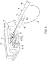
- FIG. 5 is a perspective view for illustrating a procedure when the fore-ends Wa1 of the conductor exposed portions Wa are inserted into the insertion hole 12 of the box 11 of the housing body 10.
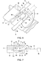
- FIG. 6 is a perspective view for illustrating a procedure of bending the middle portions of the conductor exposed portions Wa into a U shape on the lower surface KB side of the housing body 10.
- FIG. 5 corresponds to a detailed diagram for illustrating the process in FIG. 3(a) .
- FIG. 6 corresponds to a detailed diagram for illustrating the process in FIG. 3(b) .
- FIG. 7 is a view for illustrating a method of incorporating the conductor exposed portions Wa at the fore-ends of the harnesses W into the housing body 10 and is a cross-sectional side view which shows a state that the conductor exposed portions Wa at the fore-ends of the harnesses W are about to be inserted into the insertion hole 12 of the housing body 10 from the front.
- FIG. 8 is a cross-sectional side view showing a state that parts bent into a hook shape of the fore-ends Wa1 of the conductor exposed portions Wa are hooked in the through holes 21 after the state of FIG. 7 .
- FIG. 8 is a cross-sectional side view showing a state that parts bent into a hook shape of the fore-ends Wa1 of the conductor exposed portions Wa are hooked in the through holes 21 after the state of FIG. 7 .
- FIG. 9 is a cross-sectional side view showing a state that the middle portions of the conductor exposed portions Wa are bent into a U shape on the lower surface KB side of the housing body 10 and the base-end sides of the harnesses W are extended rearward after the state of FIG. 8 .
- FIG. 7 and FIG. 8 correspond to cross-sectional views for illustrating the process in FIG. 3(a) .
- FIG. 9 corresponds to a cross-sectional view for illustrating the process in FIG. 3(b) .
- FIG. 10 is a cross-sectional side view showing a state in which the cover 50 is coupled with the housing body 10 in the state of FIG. 9 to thereby clamp the base-end sides of the harnesses W between the housing body 10 and the cover 50 to complete the connector 2 and the insertion piece 201 of the mating connector 200 is about to be inserted into the connector 2, the connector 2 taking the fore-end sides of the conductor exposed portions Wa as electric contacts inside the insertion hole 12.
- FIG. 10 is a cross-sectional view showing a state corresponding to FIG. 4 .
- the fore-ends Wa1 of the conductor exposed portions Wa of the harnesses W are inserted into the insertion hole 12 of the housing body 10 from the front.
- the fore-ends Wa1 of the conductor exposed portions Wa are bent downward into a hook shape, and the hook parts are hooked into the through holes 21 of the lower plate 11a of the housing body 10 (an operation indicated by an arrow S1 in FIG. 5 and FIG. 7 ).
- the fore-end sides of the conductor exposed portions Wa can be disposed on the harness guide grooves 23 based on the parts hooked in the through holes 21.
- the middle portions of the conductor exposed portions Wa are bent downward while being fitted into the notches 24 arranged in the front end edge KC of the lower plate 11a. Furthermore, the middle portions of the conductor exposed portions Wa are further bent into a U shape with the front end edge KC of the lower plate 11a as a bending fulcrum (an operation indicated by an arrow S2 in FIG. 6 and FIG. 9 ).
- the bending operation is performed in a state that the fore-ends Wa1 of the conductor exposed portions Wa are constrained to the through holes 21, the bending can be stably and easily performed.
- the bending operation of the conductor exposed portions Wa can be performed while a state of hooking the fore-ends Wa1 of the conductor exposed portions Wa in the through holes 21 is confirmed through the window 15.
- the notches 24 are used for bending, and thus the conductor exposed portions Wa can be bent at stable positions without lateral displacement.
- the base-end sides of the conductor exposed portions Wa guided to the lower surface KB side of the lower plate 11a after being bent is, as shown in FIG. 6 , housed in the hinge support grooves 26 of the harness support portions 25 arranged on the lower surface KB side of the lower plate 11a.
- the parts of the harnesses W with the coatings Wb extending further toward the base-end sides of the harnesses W than the conductor exposed portions Wa are housed in the harness guide grooves 22 in a state of extending rearward of the connector housing 1.
- the base-end sides of the conductor exposed portions Wa at the fore-ends of the harnesses W introduced from the rear toward the front are disposed on the lower surface KB (the first plate surface) of the lower plate 11a of the housing body 10.
- the U-shaped bent portions of the conductor exposed portions Wa are disposed at the front end edge KC of the lower plate 11a.
- the fore-end sides of the conductor exposed portions Wa are disposed on the upper surface KA (the second plate surface) side of the lower plate 11a.
- the fore-end sides of the conductor exposed portions Wa are disposed in the harness guide grooves 23 formed on the upper surface of the lower plate 11a and are thereby configured as electric contacts in conductive contact with the electric contacts 202 on the lower surface of the insertion piece 201 of the mating connector 200.
- the harnesses W are clamped between the housing body 10 and the cover 50.
- the cover 50 when the cover 50 is coupled to the housing body 10 in this way, the front frame portion 52 which is a front projecting piece of the cover 50 is engaged with the front end of the housing body 10, and the rear projecting piece 53 of the cover 50 is engaged with the rear end of the housing body 10. Therefore, the movement of the housing body 10 in the front-rear direction can be restricted by the cover 50, and the integral coupling property between the cover 50 and the housing body 10 can be enhanced.
- the front frame portion 52 of the cover 50 can be disposed in close contact with the front end surface of the box 11 of the housing body 10.
- the insertion piece 201 of the mating connector 200 can be inserted into the insertion hole 12 of the housing body 10 through the opening 52a of the front frame portion 52 of the cover 50 and the receiving port 12a (an operation indicated by an arrow M in FIG. 10 ). Then, the electric contacts 202 on the lower surface of the inserted insertion piece 201 can be brought into sliding contact with the conductor exposed portions Wa (the electric contacts) supported on the harness guide grooves 23 of the lower plate 11a of the insertion hole 12.
- the mating connector 200 is fitted to the housing body 10 through the opening 52a of the front frame 52 having a size covering the entire front end surface of the housing body 10, the coupling property between the housing body 10, the cover 50 and the mating connector 200 is also increased. Therefore, when an external force in the front-rear direction acts on the connector 2 via the harnesses W or the mating connector 200, the coupling between the housing body 10 and the cover 50 can also be prevented from being misaligned or detached. Furthermore, since the front frame portion 52 and the mating connector 200 are fitted, the cover 50 is supplementarily supported by the mating connector 200. Thus, the cover 50 can be reliably prevented from falling off the housing body 10.
- FIG. 11 is a diagram for illustrating another method for incorporating the conductor exposed portions Wa at the fore-ends of the harnesses W in the housing body 10, and is a cross-sectional side view which shows a state that the conductor exposed portions Wa at the fore-ends of the harnesses W are about to be inserted into the insertion hole 12 of the housing body 10 from the front.
- FIG. 12 is a cross-sectional side view showing a state in which after the state of FIG.
- the middle portions of the conductor exposed portions Wa are bent into a U shape on the lower surface KB side of the housing body 10, the base-end sides of the harnesses W are extended rearward, and the cover 50 is coupled to the housing body 10 in this state, and thereby the base-end sides of the harnesses W are clamped between the housing body 10 and the cover 50, the connector 2 in which the fore-end sides of the conductor exposed portions Wa serve as the electric contacts inside the insertion hole 12 is completed, and the insertion piece 201 of the mating connector 200 is about to be inserted into the connector 2.
- the fore-ends Wa1 of the conductor exposed portions Wa are inserted into the insertion hole 12 while the conductor exposed portions Wa of the harnesses W are placed in the harness guide grooves 23 of the housing body 10. Besides, the fore-ends Wa1 of the conductor exposed portions Wa in an unbent state are abutted against the conical guide walls 28 of the rear wall 13 at the depth of the insertion hole 12. Then, the fore-ends Wa1 of the conductor exposed portions Wa are held inside the conical guide walls 28, and the fore-ends Wa1 of the conductor exposed portions Wa can be guided downward.
- the middle portions of the conductor exposed portions Wa are bent into a U shape inside the notches 24 with the front end edge KC of the lower plate 11a as the bending fulcrum.
- the fore-ends Wa1 of the conductor exposed portions Wa do not float due to the reaction caused by the bending. Therefore, the bending can be stably performed.
- positions of the fore-ends Wa1 of the conductor exposed portions Wa can be confirmed from the upper side or the lower side of the housing body 10 through the window 15 or the through holes 21. Accordingly, bending failure due to the reaction during the bending can be prevented, and precision of the positions of the conductor exposed portions Wa arranged in the harness guide grooves 23 and the positions of the bending can be improved.
- the harnesses W After being bent into a U-shape, the harnesses W are arranged as in the previous example, the hinge 60 (see FIG. 1 and FIG. 2 ) is bent, and the main plate 51 of the cover 50 is brought into surface matching with the lower surface KB of the housing body 10. Then, by engaging the engagement claw 56 of the cover 50 with the engagement claw 16 of the housing body 10, the harnesses W are clamped between the housing body 10 and the cover 50 as shown in FIG. 12 . Thereby, the connector 2 can be completed.
- the conductor exposed portions Wa in an unbent state are inserted into the housing body 10, and the middle portions of the exposed conductor portion Wa are bent into a U shape using the front end edge KC of the lower plate 11a.
- the conductor exposed portions Wa may be previously bent in a U shape, and the conductor exposed portions Wa bent in a U shape may be incorporated into the housing body 10.
- the U-shaped bent portions are arranged at the front end edge KC of the housing body 10, and the sides of the conductor exposed portions Wa closer to the fore-end than the U-shaped bent portions are inserted into the insertion hole 12 and are arranged in the harness guide grooves 23 on the upper surface KA side of the lower plate 11a.
- the sides of the conductor exposed portions Wa closer to the base-end than the U-shaped bent portions are disposed in the harness support grooves 26 of the lower surface KB of the lower plate 11a of the housing body 10, and the parts of the harnesses W with the coatings Wb are disposed in the harness guide grooves 22.
- the subsequent procedures are the same as described above.
- the housing body 10 may also be configured in a manner that the parts of the conductor exposed portions Wa of the harnesses W closer to the base-end sides than the U-shaped bent portions are disposed on the upper surface KA of the lower plate 11a, and the fore-ends Wa1 of the conductor exposed portions Wa of the harnesses W are disposed on the lower surface KB of the lower plate 11a.
- FIG. 14-FIG. 17 a connector housing according to a second embodiment of the present invention and a connector configured using the connector housing are described with reference to FIG. 14-FIG. 17 .
- the difference between the first embodiment described above and the second embodiment is that the connector housing 1 of the first embodiment has a one-component configuration in which the housing body 10 and the cover 50 are connected by the hinge 60, whereas the connector housing of the second embodiment has a two-component configuration in which the housing body and the cover are separated.
- the base-end sides of the conductor exposed portions Wa are disposed on the lower surface KB side of the lower plate 11a of the housing body 10, and the fore-end sides of the conductor exposed portions Wa are disposed on the upper surface KA side of the lower plate 11a of the housing body 10. Besides, the fore-end sides of the conductor exposed portions Wa serve as the electric contacts.
- the base-end sides of the conductor exposed portions Wa are disposed on an upper surface KA side of a lower plate 11a of a housing body 10, and the fore-end sides of the conductor exposed portions Wa are disposed on a lower surface KB of the lower plate 11a of the housing body 10.
- the fore-end sides of the conductor exposed portions Wa serve as electric contacts.
- positions in which the fore-ends of the harnesses W are introduced into the connector housing differ between the first embodiment and the second embodiment. That is, in the first embodiment, the introduction positions are between the lower surface KB of the housing body 10 and the cover 50. On the other hand, in the second embodiment, the introduction positions are penetration holes 121 (described later) in a rear wall 113 of the housing body 110.
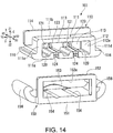
- FIG. 14 is a perspective view in which a state before use of a connector housing 101 in the second embodiment of the present invention is viewed from a diagonally upper front side
- FIG. 15 is a perspective view viewed from a diagonally lower front side.
- the connector housing 101 of the second embodiment shown in FIG. 14 and FIG. 15 is also a main component for configuring a two-wire type connector connected to a power supply terminal (a mating connector) of a hub dynamo.
- the connector housing 101 of this embodiment has the housing body 110 and a cover 150 which are separately molded from resin. Since the directionality of the members is the same as that of the first embodiment, the description thereof is omitted.
- the housing body 110 has a box 111 being a rectangular shape in which the dimension in the up-down direction is smaller than the dimension in the left-right direction when viewed from the front.
- the box 111 is configured by surrounding four sides with a lower plate 111a, an upper plate 111b facing the lower plate 111a, and a left plate 111c and a right plate 111d connecting the lower plate 111a and the upper plate 111b.
- the inside of the box 111 is configured as an insertion hole 112 into which a strip-like insertion piece 201 (see FIG. 4 ) of a mating connector 200 is inserted.
- a front surface of the insertion hole 112 is open as a receiving port 112a for receiving the insertion piece 201 of the mating connector 200.
- a depth portion of the insertion hole 112 of the box 111 is blocked by the rear wall 113.
- Outer peripheral surfaces of upper half portions of the left plate 111c and the right plate 111d of the box 111 and an outer peripheral surface of the upper plate 111b of the box 111 are integrated so as to cover a plate-shaped rib 114 having a U shape in a front view.
- Engagement claws 116 (coupling parts) are respectively arranged on outer sides of a left end portion and a right end portion of the lower plate 111a of the box 111.
- the lower plate 111a of the box 111 is configured as a board for assembling the conductor exposed portions Wa at the fore-ends of the harnesses W.
- the lower plate 111a serving as the board has parts which function as a first plate surface, a front end edge, and a second plate surface described later, respectively. That is, the lower plate 111a serving as the board has a front end edge KC where the U-shaped bent portions of the conductor exposed portions Wa are disposed.
- the lower plate 111a has an upper surface KA (an inner bottom surface of the insertion hole 12) serving as the first plate surface where parts of the conductor exposed portions Wa closer to the base-end sides than the U-shaped bent portions are disposed along the front-rear direction.
- the lower plate 111a has a lower surface KB serving as the second plate surface where parts of the conductor exposed portions Wa closer to the fore-end sides than the U-shaped bent portions are disposed along the front-rear direction.
- harness holding projection portions 120 are arranged in parallel and spaced from each other in the left-right direction Y.
- harness guide grooves (harness guide portions) 123 are arranged on which the fore-end sides of the conductor exposed portions Wa are placed.
- notches 124 are arranged which guide the bending when the middle portions of the conductor exposed portions Wa are bent into a U shape and serve as fulcrums for bending, the notches 124 being V-shaped or U-shaped when viewed from above.
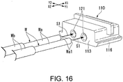
- the rear wall 113 which blocks a rear end of the box 111, two penetration holes 121 into which the conductor exposed portions Wa are inserted from the rear are arranged.
- the penetration holes 121 are positioned on extension of the harness guide grooves 123 in a manner that the conductor exposed portions Wa introduced from the penetration holes 121 are directly placed on the harness guide grooves 123.
- two harness support grooves 126 are arranged corresponding to the two harness guide grooves 123 on the upper surface KA of the lower plate 111a.
- the harness support grooves 126 extend rearward from the front end edge of the lower plate 111a and have fore-ends which are dead ends.
- the lower surface KB of the housing body 110 is a plate surface in surface matching with the cover 150 is.
- the cover 150 has a main plate 151 including a plate surface which is in surface matching with the lower surface KB of the housing body 110.
- the plate surface which is visible from above is a matching surface of the main plate 151.
- the fore-end sides of the conductor exposed portions Wa are clamped between the plate surface and the lower surface KB of the housing body 110.
- two harness support grooves 154 are arranged corresponding to the harness support grooves 126 on the lower surface of the housing body 110.
- the harness support grooves 154 also extend rearward from a front end edge of the main plate 151 and have fore-ends which are dead ends.
- Engagement claws 156 (coupling part) which are elastically engaged with the engagement claws 116 on the housing body 110 side when the main plate 151 is matched with the housing body 110 are arranged on both end portions in the left-right direction of the main plate 151.
- the engagement claws 116, 156 are engaged with each other when the housing body 110 and the cover 150 are brought into surface matching in the state that the harnesses W are clamped between the housing body 110 and the cover 150, and thereby the housing body 110 and the cover 50 are coupled integrally.
- the coupling between the housing body 110 and the cover 150 can be released.
- a front frame portion 152 is arranged as a front projecting piece at the front end of the cover 150.
- the front frame portion 152 is arranged to cover the front surface of the housing body 110 when the cover 150 is coupled to the housing body 110.
- the front frame portion 152 can restrict the housing body 110 from moving forward in a state of being engaged with the front end of the housing body 110.
- an opening 152a which opens the receiving port 112a of the insertion hole 112 of the housing body 110 at the front is arranged in the front frame portion 152.
- a rear projecting piece 153 is arranged at the rear end of the cover 150.
- the rear projecting piece 153 is engaged with the rear end of the housing body 110 when the cover 150 is coupled to the housing body 110. Thereby, the housing body 110 is restricted from moving rearward.
- FIG. 16 is a perspective view showing a state that the conductor exposed portions Wa at the fore-ends of the harnesses W are about to be inserted from the rear into the penetration holes 121 which are arranged in the rear wall 113 of the housing body 110 of the connector housing 101.
- FIG. 17 is a perspective view showing a state that the fore-end sides of the conductor exposed portions Wa inserted into the housing body 110 after the state of FIG. 16 are about to be bent in a U shape on the lower surface side of the housing body 110.
- the fore-ends Wa1 of the conductor exposed portions Wa of the harnesses W are inserted into the insertion hole 112 from the penetration holes 121 arranged on the rear wall 113 of the connector housing 101 (an operation indicated by an arrow S1).
- the base-end sides of the inserted conductor exposed portions Wa are placed on the harness guide grooves 123 as shown in FIG. 17 .
- the fore-end sides of the conductor exposed portions Wa protruding from the harness guide grooves 123 are bent downward while the middle portions are housed in the notches 124, and are directly bent in a U shape along the lower surface KB of the housing body 110 (an operation indicated by an arrow S2).
- the base-end sides of the conductor exposed portions Wa are held and fixed in the penetration holes 121, the bending can be stably and easily performed. Then, the fore-end sides of the conductor exposed portions Wa are disposed in the harness support grooves 126 of the lower surface KB of the housing body 110.
- the main plate 151 of the cover 150 is brought into surface matching with the lower surface KB of the housing body 10 (an operation indicated by an arrow F in FIG. 17 ). Then, the engagement claws 156 of the cover 150 are engaged with the engagement claws 116 of the housing body 110. Thereby, the fore-end sides of the conductor exposed portions Wa of the harnesses W can be clamped between the lower surface KB of the lower plate 111a of the housing body 110 and the main plate 151 of the cover 150.
- the connector is completed.
- the base-end sides of the conductor exposed portions Wa at the fore-ends of the harnesses W introduced from the rear toward the front are disposed on the upper surface KA (the first plate surface) of the lower plate 111a of the housing body 110.
- the U-shaped bent portions of the conductor exposed portions Wa are arranged at the front end edge KC of the lower plate 111a.
- the fore-end sides of the conductor exposed portions Wa are arranged on the lower surface KB (the second plate surface) side of the lower plate 111a.
- the base-end sides of the conductor exposed portions Wa are disposed in the harness guide grooves 123 formed on the upper surface of the lower plate 111a and are thereby configured as electric contacts in conductive contact with the electric contacts 202 on the lower surface of the insertion piece 201 of the mating connector 200.
- the fore-end sides of the conductor exposed portions Wa are clamped between the housing body 110 and the cover 150.
- the cover 150 when the cover 150 is coupled to the housing body 110 in this way, the front frame portion 152 which is the front projecting piece of the cover 150 is engaged with the front end of the housing body 110, and the rear projecting piece 153 of the cover 150 is engaged with the rear end of the housing body 110. Therefore, the movement of the housing body 110 in the front-rear direction can be restricted by the cover 150, and the integral coupling property between the cover 150 and the housing body 110 can be enhanced.
- the bent portions of the conductor exposed portions Wa can be housed inside the notches 124, protrusion caused by the bending does not occur at the front end of the lower plate 111a of the housing body 110. Therefore, the front frame portion 152 of the cover 150 can be disposed in close contact with the front end surface of the box 111 of the housing body 110.
- the insertion piece 201 of the mating connector 200 can be inserted into the insertion hole 112 of the housing body 110 through the opening 152a of the front frame portion 152 of the cover 150 and the receiving port 112a. Then, the electric contacts 202 on the lower surface of the inserted insertion piece 201 can be brought into sliding contact with the conductor exposed portions Wa (the electric contacts) supported on the harness guide grooves 123 of the lower plate 111a of the insertion hole 112.
- the mating connector 200 is fitted into the housing body 110 through the opening 152a of the front frame portion 152 having a size covering the entire front end surface of the housing body 110, coupling property between the housing body 110, the cover 150, and the mating connector 200 is also increased. Therefore, when an external force in the front-rear direction acts on the connector via the harnesses W or the mating connector 200, the coupling between the housing body 110 and the cover 150 can also be prevented from being misaligned or detached.
- the conductor exposed portions Wa when the conductor exposed portions Wa are bent into a U shape, the conductor exposed portions Wa can also be pushed and bent by the cover 150. In that case, the cover 150 is directly coupled to the housing body 110, and thereby the fore-end sides of the conductor exposed portions Wa can be clamped between the housing body 110 and the cover 150.
- the present invention is not limited to the above-described embodiments, and includes various modifications made to the above-described embodiments without departing from the gist of the present invention.
- the cases are shown in which two harnesses W are introduced into the connector housings 1, 101, but the number of the harnesses to be introduced may also be one or three or more. Accordingly, the number of the parts for supporting the conductor exposed portions may be changed.
Landscapes
- Details Of Connecting Devices For Male And Female Coupling (AREA)
- Connector Housings Or Holding Contact Members (AREA)
- Connection Or Junction Boxes (AREA)
Abstract
Description
- The present invention relates to a connector housing for configuring a connector in which a conductor exposed portion at a fore-end of a harness is directly used as an electric contact, and relates to a connector configured using the connector housing.
- A connector is known which uses a conductor exposed portion at a fore-end of a harness (electric wire) directly as an electric contact. Since this type of connector can omit a terminal fitting, the connector can be configured simply. Therefore, for example, the connector is used as a connector for connecting a power supply terminal of a bicycle hub dynamo and a lamp.
- In
patent literature 1, as this type of connector, a connector is disclosed which includes a housing body (a first housing portion), a cover (a second housing portion), and a connection portion which connects the housing body and the cover. In this connector, the connector that clamps the harness between the housing body and the cover by coupling the housing body and the cover in a manner of bending the connection portion by about 90 degrees is disclosed. The connecting portion serves as one end of the coupling between the housing body and the cover.
In this connector, a middle portion of the conductor exposed portion at the fore-end of the harness is bent into a U shape at a front end edge of the board to prevent the harness from coming out, and a part of the conductor exposed portion serves as an electric contact which is in conductive contact with an electric contact of a mating connector. - Paten literature 1: Japanese Patent Laid-open No.
2016-41591 - Meanwhile, the connector described in
patent literature 1 has a structure that when a tensile force is applied to the harness, the force is mainly received by either the housing body or the cover. Therefore, when a strong tensile force acts, the coupling between the housing body and the cover tends to misalign or detach.
In addition, inpatent literature 1 described above, the connecting portion serves as one end of the coupling between the housing body and the cover. Thus, for example, if the connection portion is damaged due to deterioration over time, an external force or the like, the cover may also fall off from the housing body. - Therefore, the present invention is completed in view of the above situations and aims to provide a connector housing with which integral coupling property of two members for clamping harness can be enhanced and the coupling is not prone to misalign or detach, and a connector which is configured using the connector housing.
- In order to solve the above problems, the connector housing according to the present invention includes: a board which supports a conductor exposed portion bent in a U shape at a fore-end of a harness when a direction in which a mating connector is fitted is set as the front, wherein the board has a front end edge where a U-shaped bent portion of the conductor exposed portion is arranged, a first plate surface on which a part of the conductor exposed portion closer to a base-end side than the U-shaped bent portion is arranged along a front-rear direction, and a second plate surface on which a part of the conductor exposed portion closer to a fore-end side than the U-shaped bent portion is arranged along the front-rear direction; a harness guide portion which is arranged on one plate surface of the first plate surface and the second plate surface and support the part on the fore-end side or the part on the base-end side of the conductor exposed portion which is arranged on the one plate surface, the part serving as an electric contact which is in conductive contact with an electric contact of the mating connector; a cover which clamps the harness between the board and the cover by being in surface matching with other plate surface of the first plate surface and the second plate surface; a coupling part which couples the board and the cover and releases the coupling in a state when the harness is clamped therebetween; and a front projecting piece and a rear projecting piece which are arranged at a front end and a rear end of the cover, and restrict, by being respectively engaged with a front end and a rear end of the board, a position of the board in the front-rear direction when the cover is coupled to the board.
- By configuring in this way, the conductor exposed portion supported by the harness guide portion on the one plate surface of the board can function as the electric contact in conductive contact with the electric contact of the mating connector. In addition, by coupling the cover to the board, the harness can be clamped between the cover which is in surface matching with the other plate surface of the board and the board.
For example, in a first example (a first embodiment) in which the other plate surface is set as the first plate surface and the one plate surface is set as the second plate surface, the U-shaped bent portion of the conductor exposed portion at the fore-end of the harness is arranged on the front end edge. In addition, the part of the conductor exposed portion closer to the base-end side than the U-shaped bent portion is arranged on the first plate surface (the other plate surface) along the front-rear direction. In addition, the part of the conductor exposed portion closer to the fore-end side than the U-shaped bent portion is arranged on the second plate surface (the one plate surface) along the front-rear direction. In this state, the cover is coupled to the board, and the cover is brought into surface matching with the first plate surface (the other plate surface). Thereby, the base-end side of the conductor exposed portion can be clamped between the first plate surface (the other plate surface) of the board and the cover. At the same time, by supporting the fore-end side of the conductor exposed portion with the harness guide portion on the second plate surface (the one plate surface), the part on the fore-end side of the conductor exposed portion can function as the electric contact which is in conductive contact with the electric contact of the mating connector.
On the contrary, in a second example (a second embodiment) in which the other plate surface is set as the second plate surface and the one plate surface is set as the first plate surface, the U-shaped bent portion of the conductor exposed portion at the fore-end of the harness is arranged on the front end edge. In addition, the part of the conductor exposed portion closer to the base-end side than the U-shaped bent portion is arranged on the first plate surface (the one plate surface) along the front-rear direction. In addition, the part of the conductor exposed portion closer to the fore-end side than the U-shaped bent portion is arranged on the second plate surface (the other plate surface) along the front-rear direction. In this state, the cover is coupled to the board, and the cover is brought into surface matching with the second plate surface (the other plate surface), and thereby the fore-end side of the conductor exposed portion can be clamped between the second plate surface (the other plate surface) of the board and the cover. At the same time, by supporting the base-end side of the conductor exposed portion with the harness guide portion on the first plate surface (the one plate surface), the part on the base-end side of the conductor exposed portion can function as the electric contact which is in conductive contact with the electric contact of the mating connector. In addition, when the cover is coupled to the board by the coupling part in this way, the front projecting piece of the cover is engaged with the front end of the board, and the rear projecting piece of the cover is engaged with the rear end of the board. Therefore, movement of the board in the front-rear direction can be restricted by the cover, and the integral coupling property between the cover and the board can be enhanced. In addition, even when an external force in the front-rear direction acts via the harness or the mating connector, the coupling between the board and the cover can be prevented from being misaligned or detached. - The connector housing according to the present invention includes a box, wherein an insertion hole into which a insertion piece being strip-like of the mating connector is inserted is formed by enclosing four sides with a lower plate, an upper plate facing the lower plate, left and right plates connecting the lower plate and the upper plate, and an opening in a front surface serves as a receiving port of the insertion piece into the insertion hole, wherein the board is arranged as the lower plate of the box, the one plate surface of the board on which the harness guide portion is formed serves as an upper surface of the lower plate configuring an inner surface of the insertion hole, and the other plate surface of the board in surface matching with the cover to clamp the harness serves as a lower surface of the lower plate, and the front projecting piece of the cover is formed as a front frame portion which covers the front surface of the box when the cover is coupled to the box, and an opening for opening the receiving port at the front is arranged in the front frame portion.
- By configuring in this way, the insertion piece of the mating connector can be inserted into the insertion hole of the box from the receiving port which is open on the front surface of the box. Besides, the electric contact on the lower surface of the insertion piece being inserted can be brought into sliding contact with the conductor exposed portion (the electric contact) disposed on the harness guide portion on the upper surface of the lower plate (the board) of the box. In addition, the insertion piece of the mating connector can be inserted into the receiving port of the box through the opening of the front frame portion of the cover. Therefore, the front frame portion can be arranged in a size for covering the entire front end surface of the box, and the integral coupling property with the box can be further enhanced.
Furthermore, since the front frame portion and the mating connector are fitted with each other, the cover is supplementarily supported by the mating connector. Thus, the cover can be reliably prevented from falling off the box. - In the connector housing according to the present invention, a notch where the U-shaped bent portion of the conductor exposed portion is housed is arranged at a front edge portion of the harness guide portion.
- By configuring in this way, when the conductor exposed portion is bent at the front end edge of the board, the bending can be easily performed at a stable position without lateral displacement. In addition, since the bent place of the conductor exposed portion can be housed inside the notch, a protrusion caused by the bending is not prone to occur at the front end of the board (the lower plate of the box), and the front frame portion of the cover is easily brought into close contact with to the front end surface of the box.
- In the connector housing according to the present invention, the connector housing is provided that a through hole which penetrate from the one plate surface to the other plate surface of the board is arranged at a rear portion of the harness guide portion.
- By configuring in this way, the fore-end of the conductor exposed portion is hooked in the through hole arranged in the lower plate (the board), and the fore-end side of the conductor exposed portion can be arranged in the harness guide portion. Besides, in this state, for example, the middle portion of the conductor exposed portion can be bent into a U shape with the front end edge of the lower plate (the board) as a bending fulcrum. Therefore, since the bending operation can be performed in a state that the fore-end of the conductor exposed portion is constrained by the through hole, the bending work can be performed particularly stably and easily. In addition, a position of the fore-end of the conductor exposed portion inside the box can be confirmed from the outside through the through hole regardless of whether or not the fore-end of the conductor exposed portion is hooked in the through hole arranged in the lower plate (the board). Therefore, precision of the position of the conductor exposed portion arranged in the harness guide portion or the bending position can be enhanced.
- In the connector housing according to the present invention, a window through which the through hole can be visually recognized from the outside is arranged in the upper plate of the box.
- By configuring in this way, the hooked state of the conductor exposed portion to the through hole can be confirmed by watching through the window, and the bending work of conductor exposed portion or the like can be performed while the hooked state is confirmed.
- In the connector housing according to the present invention, the box is arranged as a part of a housing body, and the cover is integrally connected to the housing body via a bendable hinge.
- By configuring in this way, the connector housing can be made of an integrally molded resin product. In addition, by bending the hinge, the cover can be coupled to the housing body in a state that the cover is aligned.
- A connector according to the present invention is configured to introduce the fore-end of the harness to the above connector housing, wherein the U-shaped bent portion of the conductor exposed portion at the fore-end of the harness is arranged at a front end edge of the board, the part of the conductor exposed portion closer to the fore-end side than the U-shaped bent portion is arranged on the first plate surface of the board along the front-rear direction, and the part of the conductor exposed portion closer to the base-end side than the U-shaped bent portion is arranged on the second plate surface of the board along the front-rear direction; the part on the fore-end side or the part on the base-end side of the conductor exposed portion is disposed in the harness guide portion which is arranged on one plate surface of the first plate surface and the second plate surface, and thereby the base-end side or the fore-end side of the conductor exposed portion is configured as an electric contact which is in conductive contact with an electric contact of the mating connector; the harness is clamped between the cover and the board by bringing the cover into surface matching with the other plate surface of the first plate surface and the second plate surface of the board; and the cover is coupled to the board by the coupling part in this state, and thereby the front projecting piece and the rear projecting piece which are formed in the cover are respectively engaged with the front end and the rear end of the board.
- By configuring in this way, movement of the board in the front-rear direction can be restricted by the cover, and the integral coupling property between the cover and the board can be enhanced. In addition, even when an external force in the front-rear direction acts via the harness or the mating connector, the coupling between the board and the cover can be prevented from being misaligned or detached.
- According to the present invention, the movement of the board in the front-rear direction can be restricted by the cover, and the integral coupling property between the cover and the board can be enhanced. In addition, even when an external force in the front-rear direction acts via the harness or the mating connector, the coupling between the board and the cover can be prevented from being misaligned or detached.
-
-
FIG. 1 are perspective views showing a state before use of a connector housing in a first embodiment of the present invention, where (a) is a perspective view viewed from the front, and (b) is a perspective view viewed from the rear with the top and the bottom turned upside down. -
FIG. 2 are diagrams showing a state before use of the connector housing in the first embodiment of the present invention, where (a) is a front view viewed from the front, and (b) is a rear view viewed from the rear with the top and the bottom turned upside down. -
FIG. 3 are illustration views of a method for assembling a connector by using the connector housing according to the first embodiment of the present invention, where (a) is a perspective view showing a state that conductor exposed portions at fore-ends of harnesses are about to be inserted into a housing body from the front, (b) is a perspective view showing a state that base-end sides of the harnesses are bent and extended rearward, and (c) is a perspective view showing a state that a cover is coupled to the housing body and the connector is completed. -
FIG. 4 is a perspective view showing a state that a mating connector is about to be fitted to the completed connector in the first embodiment of the present invention. -
FIG. 5 is a perspective view for illustrating a procedure when the fore-ends of the conductor exposed portions are inserted into an insertion hole of a box of the housing body in the first embodiment of the present invention. -
FIG. 6 is a perspective view for illustrating a procedure of bending middle portions of the conductor exposed portions in the first embodiment of the present invention into a U shape on a lower surface side of the housing body. -
FIG. 7 is a diagram for illustrating a method of incorporating the conductor exposed portions at the fore-ends of the harnesses into the housing body in the first embodiment of the present invention and is a cross-sectional side view which shows a state that the conductor exposed portions at the fore-ends of the harnesses are about to be inserted into the insertion hole of the housing body. -
FIG. 8 is a cross-sectional side view showing a state that the fore-ends of the conductor exposed portions are hooked in through holes after the state ofFIG. 7 . -
FIG. 9 is a cross-sectional side view showing a state that the middle portions of the conductor exposed portions are extended rearward after the state ofFIG. 8 . -
FIG. 10 is a cross-sectional side view showing a state that the connector is completed in the state ofFIG. 9 and an insertion piece of the mating connector is about to be inserted into the connector. -
FIG. 11 is a diagram for illustrating another method for incorporating the conductor exposed portions at the fore-ends of the harnesses into the housing body in the first embodiment of the present invention and is a cross-sectional side view which shows a state that the conductor exposed portions at the fore-ends of the harnesses are about to be inserted into the insertion hole of the housing body. -
FIG. 12 is a cross-sectional side view showing a state that the connector is completed after the state ofFIG. 11 and the insertion piece of the mating connector is about to be inserted into the connector. -
FIG. 13 is a cross-sectional side view of a connector in a modification example of the first embodiment of the present invention. -
FIG. 14 is a perspective view in which a state before use of a connector housing in a second embodiment of the present invention is viewed from a diagonally upper front side. -
FIG. 15 is a perspective view in which the state before use of the connector housing in the second embodiment of the present invention is viewed from a diagonally lower front side. -
FIG. 16 is a perspective view showing a state that conductor exposed portions at fore-ends of harnesses are about to be inserted into penetration holes of a housing body of the connector housing in the second embodiment of the present invention. -
FIG. 17 is a perspective view showing a state that the fore-end sides of the conductor exposed portions inserted into the housing body after the state ofFIG. 16 are about to be bent in a U shape on a lower surface side of the housing body. - Embodiments of the present invention are described below with reference to the drawings.
- A connector described here is useful as a two-wire type connector which is connected to a power supply terminal (a mating connector) of a hub dynamo of a bicycle, and can also be used widely as other general electrical connectors. In a first embodiment, an example is shown where a connector housing configuring the connector is configured by one component (an integrally molded product). Besides, in a second embodiment, an example is shown where a connector housing configuring the connector is configured by two components (separately molded products).
- The connector housing of the first embodiment of the present invention and a connector configured using the connector housing are described with reference to
FIG. 1-FIG. 12 . -
FIG. 1 are perspective views showing a state before use of aconnector housing 1 in the first embodiment of the present invention, where (a) is a perspective view viewed from the front, and (b) is a perspective view viewed from the rear with the top and the bottom turned upside down.FIG. 2 are diagrams showing a state before use of theconnector housing 1, where (a) is a front view viewed from the front, and (b) is a rear view viewed from the rear with the top and the bottom turned upside down.FIG. 3 are illustration views of a method for assembling aconnector 2 by using theconnector housing 1, where (a) is a perspective view showing a state that conductor exposed portions Wa at fore-ends Wa1 of harnesses W are about to be inserted into ahousing body 10 from the front, (b) is a perspective view showing a state that base-end sides of the harnesses W are bent and extended rearward, and (c) is a perspective view showing a state that acover 50 is coupled to thehousing body 10 and theconnector 2 is completed.FIG. 4 is a perspective view showing a state that amating connector 200 is about to be fitted to the completedconnector 2. - The
connector housing 1 of the first embodiment shown inFIG. 1 andFIG. 2 is a main component for configuring a two-wire connector connected to a power supply terminal (the mating connector) of a hub dynamo. Theconnector housing 1 is integrally molded by resin and includes thehousing body 10, thecover 50, and ahinge 60 which connects thehousing body 10 and thecover 50. - Here, prior to the following description, directionality is defined in advance as follows.
- Each direction described below indicates a direction in the state of the
connector 2 finally completed (seeFIG. 3(c) andFIG. 4 ). First, a direction in which a mating connector is received while being fitted to the mating connector (the power supply terminal of the hub dynamo or the like) is referred to as the front (a front side) X1, and the opposite direction is referred to as a rear direction (a rear side) X2, and a front-rear direction is represented by X. Accordingly,FIG. 1(a) is a diagram viewed from diagonally front, andFIG. 1(b) is a diagram viewed from diagonally rear. In addition, a left side ofFIG. 1(a) when viewed from the front is referred to as the left (a left side) Y1 of theconnector housing 1, a right side ofFIG. 1(a) when viewed from the front is referred to as the right (a left side) Y1, and a left-right direction is represented by Y. In addition, a direction where thehousing body 10 and thecover 50 are coupled is referred to as an up-down direction Z, and in the coupled state, a direction where thehousing body 10 is positioned is referred to as the up (an upper side) Z1, and a direction where thecover 50 is positioned is referred to as the down (a lower side) Z2. - By being combined with the fore-ends of the harnesses, the
connector housing 1 configures a connector without using a terminal fitting. - As shown in
FIG. 3(c) andFIG. 4 , in the finally completedconnector 2, the harnesses W extend rearward from theconnector 2. Therefore, when viewed from the harnesses W extending rearward from theconnector 2, the fore-ends of the harnesses W are introduced from the rear toward the front with respect to theconnector 2. For example, even if the fore-ends of the harnesses W are introduced from the front toward the rear in the middle of the assembly as shown inFIG. 3(a) , when theconnector 2 is finally completed, as shown inFIG. 3(c) , the fore-ends of the harnesses W are introduced from the rear to the front. - As shown in
FIG. 1 andFIG. 2 , thehousing body 10 of theconnector housing 1 has abox 11 being a rectangular shape in which the dimension in the up-down direction is smaller than the dimension in the left-right direction when viewed from the front. Thebox 11 is configured by surrounding four sides with alower plate 11a, anupper plate 11b facing thelower plate 11a, and aleft plate 11c and aright plate 11d that connect thelower plate 11a and theupper plate 11b. The inside of thebox 11 is configured as aninsertion hole 12 into which a strip-like insertion piece 201 (seeFIG. 4 ) of themating connector 200 is inserted. A front surface of theinsertion hole 12 is opened as a receivingport 12a for receiving theinsertion piece 201 of themating connector 200. A depth portion of theinsertion hole 12 of thebox 11 is blocked by arear wall 13. - In the
left plate 11c and theright plate 11d of thebox 11, an outer peripheral surface of an upper half portion and an outer peripheral surface of theupper plate 11b are integrated so as to cover a plate-like rib 14 having a U shape in a front view. On the outer side of a left end portion of thelower plate 11a of thebox 11, an engagement claw 16 (a coupling part) which protrudes toward the left Y1 is arranged. In addition, thecover 50 is connected to the outer side of a right end portion of thelower plate 11a of thebox 11 via thehinge 60. Accordingly, thecover 50 before assembly is arranged on the right side Y2 of thehousing body 10. - Here, as shown in
FIG. 3(a) , the harnesses W are obtained by covering harness core wires (conductive wires) Wa with insulation coatings Wb. The harness core wire Wa may be composed of a large number of strands or be composed of a single strand (a single wire). When the fore-ends of the harnesses W are introduced into theconnector housing 1, the insulation coatings Wb within a predetermined length of the fore-ends of the harnesses W are peeled off to expose the harness core wires Wa. Here, the exposed core wires Wa at the fore-ends are referred to as the conductor exposed portions Wa and are denoted by the same symbol as the conductors Wa. - As shown in
FIG. 1 andFIG. 2 , thelower plate 11a of thebox 11 is configured as a board which supports the conductor exposed portions Wa bent in a U shape at the fore-ends of the harnesses W. Thelower plate 11a serving as the board has parts which function as a first plate surface, a front end edge, and a second plate surface described below, respectively. That is, thelower plate 11a serving as the board has a front end edge KC where U-shaped bent portions of the conductor exposed portions Wa are disposed. In addition, thelower plate 11a has a lower surface KB serving as the first plate surface where parts of the conductor exposed portions Wa closer to the base-end sides than the U-shaped bent portions are disposed along the front-rear direction. In addition, thelower plate 11a has an upper surface KA (an inner bottom surface of the insertion hole 12) serving as the second plate surface where parts of the conductor exposed portions Wa closer to the fore-end sides than the U-shaped bent portions are disposed along the front-rear direction. - On the upper surface KA (corresponding to one plate surface) of the
lower plate 11a of thehousing body 10, along the front-rear direction, two harness holdingprojection portions 20 having a semi-circular cross section are arranged in parallel and spaced from each other in the left-right direction Y. On upper surfaces of the harness holdingprojection portions 20, harness guide grooves (harness guide portions) 23 are arranged on which the fore-end sides of the conductor exposed portions Wa are placed. By disposing the fore-end sides of the conductor exposed portions Wa (closer to the fore-end sides than the U-shaped bent portions) in theharness guide grooves 23, the fore-end sides of the conductor exposed portions Wa can be used as electric contacts. - At front edge portions of the
harness guide grooves 23,notches 24 are arranged which guide the bending when middle portions of the conductor exposed portions Wa are bent into a U shape and serve as fulcrums for bending, thenotches 24 being V-shaped or U-shaped when viewed from above. In addition, throughholes 21 penetrating from the upper surface KA to the lower surface KB of thelower plate 11a are arranged at positions on the rear side X2 on theharness guide grooves 23 of the harness holdingprojection portions 20. In addition, a notch-shapedwindow 15 through which the periphery of the throughholes 21 can be visually recognized from above thebox 11 is arranged in theupper plate 11b of thebox 11. In addition, on therear wall 13 which blocks the rear end of thebox 11,conical guide walls 28 are arranged. When the fore-ends Wa1 of the conductor exposed portions Wa placed on theharness guide grooves 23 are abutted against therear wall 13, theconical guide walls 28 hold the fore-ends Wa1 and guide the fore-ends Wa1 toward the lower side. - In addition, on a lower surface of the
housing body 10, that is, the lower surface KB of thelower plate 11a,harness support portions 25 which haveharness support grooves 26 are arranged corresponding to the harness holdingprojection portions 20 of the upper surface KA of thelower plate 11a. Theharness support portions 25 are arranged only in a part at a front end side of thelower plate 11a, and on rear sides of theharness support portions 25, harness guide grooves which can house the parts of the harnesses W with the coatings Wb are arranged. Inner peripheral surfaces of theharness guide grooves 22 are larger in size than inner peripheral surfaces of theharness support grooves 26 on the front side of theharness guide grooves 22 in order to house the parts of the harnesses W with the coatings Wb. Accordingly, there is a slight step at the boundary between theharness support grooves 26 and theharness guide grooves 22. - The through holes 21 formed on rear sides of the
harness guide grooves 23 on the upper surface KA side of the above-describedlower plate 11a are open at inner bottom portions of theharness guide grooves 22. Specifically, theharness guide grooves 23 are arranged on the upper surface KA side of thelower plate 11a, and theharness guide grooves 22 are arranged on the lower surface KB side of thelower plate 11a. Besides, the throughholes 21 are open by being formed at height positions where inner bottom surfaces of theharness guide grooves 23 on the upper surface KA side and inner bottom surfaces of theharness guide grooves 22 on the lower surface KB side overlap each other. Therefore, inner surfaces of theconical guide walls 28 arranged on therear wall 13 are continuous with the inner surfaces of theharness guide grooves 22 on the lower surface KB side. - The lower surface KB of the
housing body 10 is a plate surface in surface matching with thecover 50. Thecover 50 includes amain plate 51 having a plate surface which is in surface matching with the lower surface KB of thehousing body 10. The plate surface visible from above inFIG. 1(b) is the matching surface of themain plate 51. The harnesses W are clamped between the plate surface and the lower surface KB of thehousing body 10. - One side end portion of the
main plate 51 is connected to a part outside the right end portion of thelower plate 11a of thehousing body 10 via thebendable hinge 60. Thehinge 60 can be bent by 180 degrees as a whole and is configured by two stages ofhinge portions stage hinge portions lower plate 11a of thehousing body 10 and themain plate 51 of thecover 50, V-grooves 61a, 61b along the front-rear direction are respectively formed and set as thin portions. - By bending the two-
stage hinge portions cover 50 can be rotated by 180 degrees and themain plate 51 of thecover 50 can be brought into surface matching with the lower surface KB of thehousing body 10. At that time, the V-grooves 61a, 61b are crushed, and the other inclined surfaces of the V-grooves portion 63 formed by common inclined surfaces of the two V-grooves main plate 51 can be in surface matching with the lower surface KB of thehousing body 10 while eliminating the positional deviation in the left-right direction Y. - An engagement claw 56 (a coupling part) which is elastically engaged with the
engagement claw 16 on thehousing body 10 side when themain plate 51 is matched with thehousing body 10 is arranged on a side edge opposite to thehinge 60 of themain plate 51 of thecover 50. Theengagement claws housing body 10 and thecover 50 are brought into surface matching in the state that the harnesses W are clamped between thehousing body 10 and thecover 50, and thereby thehousing body 10 and thecover 50 are coupled integrally. In this case, since one end side is already coupled with thehinge 60, it is sufficient to arrange theengagement claws engagement claw 16 on thehousing body 10 side and theengagement claw 56 on thecover 50 side, the coupling between thehousing body 10 and thecover 50 can be released. - A
front frame portion 52 is arranged as a front projecting piece at the front end of thecover 50. Thefront frame portion 52 is arranged to cover the front surface of thehousing body 10 when thecover 50 is coupled to thehousing body 10. By being arranged to cover the front surface of thehousing body 10 in this way, thefront frame portion 52 can restrict thehousing body 10 from moving forward in a state of being engaged with the front end of thehousing body 10. In addition, anopening 52a which opens the receivingport 12a of theinsertion hole 12 of thehousing body 10 at the front is arranged in thefront frame portion 52. - In addition, a
rear projecting piece 53 is arranged at the rear end of thecover 50. The rear projectingpiece 53 is engaged with the rear end of thehousing body 10 when thecover 50 is coupled to thehousing body 10. Thereby, thehousing body 10 is restricted from moving rearward. - Next, a procedure of assembling the connector using the
connector housing 1 with the above configuration is described. -
FIG. 5 is a perspective view for illustrating a procedure when the fore-ends Wa1 of the conductor exposed portions Wa are inserted into theinsertion hole 12 of thebox 11 of thehousing body 10.FIG. 6 is a perspective view for illustrating a procedure of bending the middle portions of the conductor exposed portions Wa into a U shape on the lower surface KB side of thehousing body 10. Moreover,FIG. 5 corresponds to a detailed diagram for illustrating the process inFIG. 3(a) .FIG. 6 corresponds to a detailed diagram for illustrating the process inFIG. 3(b) . - In addition,
FIG. 7 is a view for illustrating a method of incorporating the conductor exposed portions Wa at the fore-ends of the harnesses W into thehousing body 10 and is a cross-sectional side view which shows a state that the conductor exposed portions Wa at the fore-ends of the harnesses W are about to be inserted into theinsertion hole 12 of thehousing body 10 from the front.FIG. 8 is a cross-sectional side view showing a state that parts bent into a hook shape of the fore-ends Wa1 of the conductor exposed portions Wa are hooked in the throughholes 21 after the state ofFIG. 7 .FIG. 9 is a cross-sectional side view showing a state that the middle portions of the conductor exposed portions Wa are bent into a U shape on the lower surface KB side of thehousing body 10 and the base-end sides of the harnesses W are extended rearward after the state ofFIG. 8 . Moreover,FIG. 7 andFIG. 8 correspond to cross-sectional views for illustrating the process inFIG. 3(a) .FIG. 9 corresponds to a cross-sectional view for illustrating the process inFIG. 3(b) . - In addition,
FIG. 10 is a cross-sectional side view showing a state in which thecover 50 is coupled with thehousing body 10 in the state ofFIG. 9 to thereby clamp the base-end sides of the harnesses W between thehousing body 10 and thecover 50 to complete theconnector 2 and theinsertion piece 201 of themating connector 200 is about to be inserted into theconnector 2, theconnector 2 taking the fore-end sides of the conductor exposed portions Wa as electric contacts inside theinsertion hole 12.FIG. 10 is a cross-sectional view showing a state corresponding toFIG. 4 . - When the
connector 2 is assembled, first, as shown inFIG. 3(a) ,FIG. 5 , andFIG. 7 , the fore-ends Wa1 of the conductor exposed portions Wa of the harnesses W are inserted into theinsertion hole 12 of thehousing body 10 from the front. At that time, the fore-ends Wa1 of the conductor exposed portions Wa are bent downward into a hook shape, and the hook parts are hooked into the throughholes 21 of thelower plate 11a of the housing body 10 (an operation indicated by an arrow S1 inFIG. 5 andFIG. 7 ). As a result, as shown inFIG. 8 , the fore-end sides of the conductor exposed portions Wa can be disposed on theharness guide grooves 23 based on the parts hooked in the through holes 21. - Next, in this state, as shown in
FIG. 3(b) ,FIG. 6 , andFIG. 9 , the middle portions of the conductor exposed portions Wa are bent downward while being fitted into thenotches 24 arranged in the front end edge KC of thelower plate 11a. Furthermore, the middle portions of the conductor exposed portions Wa are further bent into a U shape with the front end edge KC of thelower plate 11a as a bending fulcrum (an operation indicated by an arrow S2 inFIG. 6 andFIG. 9 ). - At this time, since the bending operation is performed in a state that the fore-ends Wa1 of the conductor exposed portions Wa are constrained to the through
holes 21, the bending can be stably and easily performed. In addition, the bending operation of the conductor exposed portions Wa can be performed while a state of hooking the fore-ends Wa1 of the conductor exposed portions Wa in the throughholes 21 is confirmed through thewindow 15. At the time of bending, thenotches 24 are used for bending, and thus the conductor exposed portions Wa can be bent at stable positions without lateral displacement. - The base-end sides of the conductor exposed portions Wa guided to the lower surface KB side of the
lower plate 11a after being bent is, as shown inFIG. 6 , housed in thehinge support grooves 26 of theharness support portions 25 arranged on the lower surface KB side of thelower plate 11a. In addition, the parts of the harnesses W with the coatings Wb extending further toward the base-end sides of the harnesses W than the conductor exposed portions Wa are housed in theharness guide grooves 22 in a state of extending rearward of theconnector housing 1. - In this state, as shown in
FIG. 3(c) andFIG. 10 , the hinge 60 (seeFIG. 1 andFIG. 2 ) is bent and themain plate 51 of thecover 50 is brought into surface matching with the lower surface KB of the housing body 10 (an operation indicated by an arrow F inFIG. 10 ). Then, theengagement claw 56 of thecover 50 is engaged with theengagement claw 16 of thehousing body 10. Thereby, the harnesses W can be clamped between the lower surface KB of thelower plate 11a of thehousing body 10 and themain plate 51 of thecover 50. - Through the above procedure, the
connector 2 shown inFIG. 3(c) andFIG. 10 is completed. - In this
connector 2, the base-end sides of the conductor exposed portions Wa at the fore-ends of the harnesses W introduced from the rear toward the front are disposed on the lower surface KB (the first plate surface) of thelower plate 11a of thehousing body 10. In addition, the U-shaped bent portions of the conductor exposed portions Wa are disposed at the front end edge KC of thelower plate 11a. In addition, the fore-end sides of the conductor exposed portions Wa are disposed on the upper surface KA (the second plate surface) side of thelower plate 11a. Moreover, the fore-end sides of the conductor exposed portions Wa are disposed in theharness guide grooves 23 formed on the upper surface of thelower plate 11a and are thereby configured as electric contacts in conductive contact with theelectric contacts 202 on the lower surface of theinsertion piece 201 of themating connector 200. In addition, the harnesses W are clamped between thehousing body 10 and thecover 50. - In addition, when the
cover 50 is coupled to thehousing body 10 in this way, thefront frame portion 52 which is a front projecting piece of thecover 50 is engaged with the front end of thehousing body 10, and the rear projectingpiece 53 of thecover 50 is engaged with the rear end of thehousing body 10. Therefore, the movement of thehousing body 10 in the front-rear direction can be restricted by thecover 50, and the integral coupling property between thecover 50 and thehousing body 10 can be enhanced. - In addition, because the bent portions of the conductor exposed portions Wa can be housed inside the
notches 24, protrusion caused by the bending does not occur at the front end of thelower plate 11a of thehousing body 10. Therefore, thefront frame portion 52 of thecover 50 can be disposed in close contact with the front end surface of thebox 11 of thehousing body 10. - With respect to the
connector 2 configured as described above, as shown inFIG. 4 andFIG. 10 , theinsertion piece 201 of themating connector 200 can be inserted into theinsertion hole 12 of thehousing body 10 through theopening 52a of thefront frame portion 52 of thecover 50 and the receivingport 12a (an operation indicated by an arrow M inFIG. 10 ). Then, theelectric contacts 202 on the lower surface of the insertedinsertion piece 201 can be brought into sliding contact with the conductor exposed portions Wa (the electric contacts) supported on theharness guide grooves 23 of thelower plate 11a of theinsertion hole 12. When themating connector 200 is inserted, a friction force is received in a direction in which the fore-ends Wa1 of the conductor exposed portions Wa are pushed into the deep side of theinsertion hole 12. Thus, the harnesses W are not prone to fall off theconnector housing 1. - In addition, since the
mating connector 200 is fitted to thehousing body 10 through theopening 52a of thefront frame 52 having a size covering the entire front end surface of thehousing body 10, the coupling property between thehousing body 10, thecover 50 and themating connector 200 is also increased. Therefore, when an external force in the front-rear direction acts on theconnector 2 via the harnesses W or themating connector 200, the coupling between thehousing body 10 and thecover 50 can also be prevented from being misaligned or detached.
Furthermore, since thefront frame portion 52 and themating connector 200 are fitted, thecover 50 is supplementarily supported by themating connector 200. Thus, thecover 50 can be reliably prevented from falling off thehousing body 10. - Moreover, in the above description, an example is described in which when the fore-ends Wa1 of the conductor exposed portions Wa are inserted into the
insertion hole 12 of thehousing body 10, the fore-ends Wa1 of the conductor exposed portions Wa are hooked into the throughholes 21 after the fore-ends Wa1 are bending into a hook shape. However, the present invention is not limited thereto. -
FIG. 11 is a diagram for illustrating another method for incorporating the conductor exposed portions Wa at the fore-ends of the harnesses W in thehousing body 10, and is a cross-sectional side view which shows a state that the conductor exposed portions Wa at the fore-ends of the harnesses W are about to be inserted into theinsertion hole 12 of thehousing body 10 from the front.FIG. 12 is a cross-sectional side view showing a state in which after the state ofFIG. 11 , the middle portions of the conductor exposed portions Wa are bent into a U shape on the lower surface KB side of thehousing body 10, the base-end sides of the harnesses W are extended rearward, and thecover 50 is coupled to thehousing body 10 in this state, and thereby the base-end sides of the harnesses W are clamped between thehousing body 10 and thecover 50, theconnector 2 in which the fore-end sides of the conductor exposed portions Wa serve as the electric contacts inside theinsertion hole 12 is completed, and theinsertion piece 201 of themating connector 200 is about to be inserted into theconnector 2. - As shown in
FIG. 11 , in this example, the fore-ends Wa1 of the conductor exposed portions Wa are inserted into theinsertion hole 12 while the conductor exposed portions Wa of the harnesses W are placed in theharness guide grooves 23 of thehousing body 10. Besides, the fore-ends Wa1 of the conductor exposed portions Wa in an unbent state are abutted against theconical guide walls 28 of therear wall 13 at the depth of theinsertion hole 12. Then, the fore-ends Wa1 of the conductor exposed portions Wa are held inside theconical guide walls 28, and the fore-ends Wa1 of the conductor exposed portions Wa can be guided downward. - In this state, the middle portions of the conductor exposed portions Wa are bent into a U shape inside the
notches 24 with the front end edge KC of thelower plate 11a as the bending fulcrum. In this bending, since the parts inserted into theconical guide walls 28 are fixed to theconical guide walls 28, the fore-ends Wa1 of the conductor exposed portions Wa do not float due to the reaction caused by the bending. Therefore, the bending can be stably performed. In addition, positions of the fore-ends Wa1 of the conductor exposed portions Wa (the parts inserted into the conical guide walls 28) can be confirmed from the upper side or the lower side of thehousing body 10 through thewindow 15 or the through holes 21. Accordingly, bending failure due to the reaction during the bending can be prevented, and precision of the positions of the conductor exposed portions Wa arranged in theharness guide grooves 23 and the positions of the bending can be improved. - After being bent into a U-shape, the harnesses W are arranged as in the previous example, the hinge 60 (see
FIG. 1 andFIG. 2 ) is bent, and themain plate 51 of thecover 50 is brought into surface matching with the lower surface KB of thehousing body 10. Then, by engaging theengagement claw 56 of thecover 50 with theengagement claw 16 of thehousing body 10, the harnesses W are clamped between thehousing body 10 and thecover 50 as shown inFIG. 12 . Thereby, theconnector 2 can be completed. - Moreover, in the above description, the case is described in which the conductor exposed portions Wa in an unbent state are inserted into the
housing body 10, and the middle portions of the exposed conductor portion Wa are bent into a U shape using the front end edge KC of thelower plate 11a.
However, it is not always necessary to bend the conductor exposed portions Wa into a U shape after the conductor exposed portions Wa are introduced into thehousing body 10. That is, the conductor exposed portions Wa may be previously bent in a U shape, and the conductor exposed portions Wa bent in a U shape may be incorporated into thehousing body 10. In that case, the U-shaped bent portions are arranged at the front end edge KC of thehousing body 10, and the sides of the conductor exposed portions Wa closer to the fore-end than the U-shaped bent portions are inserted into theinsertion hole 12 and are arranged in theharness guide grooves 23 on the upper surface KA side of thelower plate 11a. In addition, the sides of the conductor exposed portions Wa closer to the base-end than the U-shaped bent portions are disposed in theharness support grooves 26 of the lower surface KB of thelower plate 11a of thehousing body 10, and the parts of the harnesses W with the coatings Wb are disposed in theharness guide grooves 22. The subsequent procedures are the same as described above. - In addition, in the above description, the case is described in which the fore-ends Wa1 of the conductor exposed portions Wa of the harnesses W are disposed on the upper surface KA of the
lower plate 11a of thehousing body 10, and the parts of the conductor exposed portions Wa closer to the base-end sides than the U-shaped bent portions are disposed on the lower surface KB of thelower plate 11a.
However, as shown inFIG. 13 , thehousing body 10 may also be configured in a manner that the parts of the conductor exposed portions Wa of the harnesses W closer to the base-end sides than the U-shaped bent portions are disposed on the upper surface KA of thelower plate 11a, and the fore-ends Wa1 of the conductor exposed portions Wa of the harnesses W are disposed on the lower surface KB of thelower plate 11a. - Next, a connector housing according to a second embodiment of the present invention and a connector configured using the connector housing are described with reference to
FIG. 14-FIG. 17 . - Here, the difference between the first embodiment described above and the second embodiment is that the
connector housing 1 of the first embodiment has a one-component configuration in which thehousing body 10 and thecover 50 are connected by thehinge 60, whereas the connector housing of the second embodiment has a two-component configuration in which the housing body and the cover are separated. - That is, in the first embodiment, the base-end sides of the conductor exposed portions Wa are disposed on the lower surface KB side of the
lower plate 11a of thehousing body 10, and the fore-end sides of the conductor exposed portions Wa are disposed on the upper surface KA side of thelower plate 11a of thehousing body 10. Besides, the fore-end sides of the conductor exposed portions Wa serve as the electric contacts. In contrast, in the second embodiment, the base-end sides of the conductor exposed portions Wa are disposed on an upper surface KA side of alower plate 11a of ahousing body 10, and the fore-end sides of the conductor exposed portions Wa are disposed on a lower surface KB of thelower plate 11a of thehousing body 10. Besides, the fore-end sides of the conductor exposed portions Wa serve as electric contacts. - Due to the differences, positions in which the fore-ends of the harnesses W are introduced into the connector housing (or positions in which the harnesses W are extracted from the connector housing) differ between the first embodiment and the second embodiment. That is, in the first embodiment, the introduction positions are between the lower surface KB of the
housing body 10 and thecover 50. On the other hand, in the second embodiment, the introduction positions are penetration holes 121 (described later) in arear wall 113 of thehousing body 110. -
FIG. 14 is a perspective view in which a state before use of aconnector housing 101 in the second embodiment of the present invention is viewed from a diagonally upper front side, andFIG. 15 is a perspective view viewed from a diagonally lower front side. - The
connector housing 101 of the second embodiment shown inFIG. 14 andFIG. 15 is also a main component for configuring a two-wire type connector connected to a power supply terminal (a mating connector) of a hub dynamo. Theconnector housing 101 of this embodiment has thehousing body 110 and acover 150 which are separately molded from resin. Since the directionality of the members is the same as that of the first embodiment, the description thereof is omitted. - As shown in
FIG. 14 andFIG. 15 , thehousing body 110 has abox 111 being a rectangular shape in which the dimension in the up-down direction is smaller than the dimension in the left-right direction when viewed from the front. Thebox 111 is configured by surrounding four sides with alower plate 111a, anupper plate 111b facing thelower plate 111a, and aleft plate 111c and aright plate 111d connecting thelower plate 111a and theupper plate 111b. The inside of thebox 111 is configured as aninsertion hole 112 into which a strip-like insertion piece 201 (seeFIG. 4 ) of amating connector 200 is inserted. A front surface of theinsertion hole 112 is open as a receivingport 112a for receiving theinsertion piece 201 of themating connector 200. A depth portion of theinsertion hole 112 of thebox 111 is blocked by therear wall 113. - Outer peripheral surfaces of upper half portions of the
left plate 111c and theright plate 111d of thebox 111 and an outer peripheral surface of theupper plate 111b of thebox 111 are integrated so as to cover a plate-shapedrib 114 having a U shape in a front view. Engagement claws 116 (coupling parts) are respectively arranged on outer sides of a left end portion and a right end portion of thelower plate 111a of thebox 111. - The
lower plate 111a of thebox 111 is configured as a board for assembling the conductor exposed portions Wa at the fore-ends of the harnesses W. Thelower plate 111a serving as the board has parts which function as a first plate surface, a front end edge, and a second plate surface described later, respectively. That is, thelower plate 111a serving as the board has a front end edge KC where the U-shaped bent portions of the conductor exposed portions Wa are disposed. In addition, thelower plate 111a has an upper surface KA (an inner bottom surface of the insertion hole 12) serving as the first plate surface where parts of the conductor exposed portions Wa closer to the base-end sides than the U-shaped bent portions are disposed along the front-rear direction. In addition, thelower plate 111a has a lower surface KB serving as the second plate surface where parts of the conductor exposed portions Wa closer to the fore-end sides than the U-shaped bent portions are disposed along the front-rear direction. - On the upper surface KA (corresponding to one plate surface) of the
lower plate 111a of thehousing body 110, along the front-rear direction, two harness holdingprojection portions 120 are arranged in parallel and spaced from each other in the left-right direction Y. On upper surfaces of the harness holdingprojection portions 120, harness guide grooves (harness guide portions) 123 are arranged on which the fore-end sides of the conductor exposed portions Wa are placed. By arranging the base-end sides of the conductor exposed portions Wa (closer to the base-end sides than the U-shaped bent portions) in theharness guide grooves 123, the base-end sides of the conductor exposed portions Wa can be used as electric contacts. - At front edge portions of the
harness guide grooves 123,notches 124 are arranged which guide the bending when the middle portions of the conductor exposed portions Wa are bent into a U shape and serve as fulcrums for bending, thenotches 124 being V-shaped or U-shaped when viewed from above. In addition, on therear wall 113 which blocks a rear end of thebox 111, twopenetration holes 121 into which the conductor exposed portions Wa are inserted from the rear are arranged. The penetration holes 121 are positioned on extension of theharness guide grooves 123 in a manner that the conductor exposed portions Wa introduced from the penetration holes 121 are directly placed on theharness guide grooves 123. - In addition, on the lower surface of the
housing body 110, that is, the lower surface KB of thelower plate 111a, twoharness support grooves 126 are arranged corresponding to the twoharness guide grooves 123 on the upper surface KA of thelower plate 111a. Theharness support grooves 126 extend rearward from the front end edge of thelower plate 111a and have fore-ends which are dead ends. - The lower surface KB of the
housing body 110 is a plate surface in surface matching with thecover 150 is. Thecover 150 has amain plate 151 including a plate surface which is in surface matching with the lower surface KB of thehousing body 110. InFIG. 14 , the plate surface which is visible from above is a matching surface of themain plate 151. The fore-end sides of the conductor exposed portions Wa are clamped between the plate surface and the lower surface KB of thehousing body 110. On the matching surface of thecover 150, twoharness support grooves 154 are arranged corresponding to theharness support grooves 126 on the lower surface of thehousing body 110. Theharness support grooves 154 also extend rearward from a front end edge of themain plate 151 and have fore-ends which are dead ends. - Engagement claws 156 (coupling part) which are elastically engaged with the
engagement claws 116 on thehousing body 110 side when themain plate 151 is matched with thehousing body 110 are arranged on both end portions in the left-right direction of themain plate 151. Theengagement claws housing body 110 and thecover 150 are brought into surface matching in the state that the harnesses W are clamped between thehousing body 110 and thecover 150, and thereby thehousing body 110 and thecover 50 are coupled integrally. In addition, by disengaging the engagement between theengagement claws 116 on thehousing body 110 side and theengagement claws 156 on thecover 150 side, the coupling between thehousing body 110 and thecover 150 can be released. - A
front frame portion 152 is arranged as a front projecting piece at the front end of thecover 150. Thefront frame portion 152 is arranged to cover the front surface of thehousing body 110 when thecover 150 is coupled to thehousing body 110. By being arranged to cover the front surface of thehousing body 110 in this way, thefront frame portion 152 can restrict thehousing body 110 from moving forward in a state of being engaged with the front end of thehousing body 110. In addition, anopening 152a which opens the receivingport 112a of theinsertion hole 112 of thehousing body 110 at the front is arranged in thefront frame portion 152. - In addition, a
rear projecting piece 153 is arranged at the rear end of thecover 150. The rear projectingpiece 153 is engaged with the rear end of thehousing body 110 when thecover 150 is coupled to thehousing body 110. Thereby, thehousing body 110 is restricted from moving rearward. - Next, a procedure of assembling the connector using the
connector housing 101 with the above configuration is described. -
FIG. 16 is a perspective view showing a state that the conductor exposed portions Wa at the fore-ends of the harnesses W are about to be inserted from the rear into the penetration holes 121 which are arranged in therear wall 113 of thehousing body 110 of theconnector housing 101.FIG. 17 is a perspective view showing a state that the fore-end sides of the conductor exposed portions Wa inserted into thehousing body 110 after the state ofFIG. 16 are about to be bent in a U shape on the lower surface side of thehousing body 110. - When the connector is assembled using this
connector housing 101, first, as shown inFIG. 16 , the fore-ends Wa1 of the conductor exposed portions Wa of the harnesses W are inserted into theinsertion hole 112 from the penetration holes 121 arranged on therear wall 113 of the connector housing 101 (an operation indicated by an arrow S1). The base-end sides of the inserted conductor exposed portions Wa are placed on theharness guide grooves 123 as shown inFIG. 17 . Then, the fore-end sides of the conductor exposed portions Wa protruding from theharness guide grooves 123 are bent downward while the middle portions are housed in thenotches 124, and are directly bent in a U shape along the lower surface KB of the housing body 110 (an operation indicated by an arrow S2). At this time, since the base-end sides of the conductor exposed portions Wa are held and fixed in the penetration holes 121, the bending can be stably and easily performed. Then, the fore-end sides of the conductor exposed portions Wa are disposed in theharness support grooves 126 of the lower surface KB of thehousing body 110. - In this state, the
main plate 151 of thecover 150 is brought into surface matching with the lower surface KB of the housing body 10 (an operation indicated by an arrow F inFIG. 17 ). Then, theengagement claws 156 of thecover 150 are engaged with theengagement claws 116 of thehousing body 110. Thereby, the fore-end sides of the conductor exposed portions Wa of the harnesses W can be clamped between the lower surface KB of thelower plate 111a of thehousing body 110 and themain plate 151 of thecover 150. - Through the above procedure, the connector is completed. In this connector, the base-end sides of the conductor exposed portions Wa at the fore-ends of the harnesses W introduced from the rear toward the front are disposed on the upper surface KA (the first plate surface) of the
lower plate 111a of thehousing body 110. In addition, the U-shaped bent portions of the conductor exposed portions Wa are arranged at the front end edge KC of thelower plate 111a. In addition, the fore-end sides of the conductor exposed portions Wa are arranged on the lower surface KB (the second plate surface) side of thelower plate 111a. Moreover, the base-end sides of the conductor exposed portions Wa are disposed in theharness guide grooves 123 formed on the upper surface of thelower plate 111a and are thereby configured as electric contacts in conductive contact with theelectric contacts 202 on the lower surface of theinsertion piece 201 of themating connector 200. In addition, the fore-end sides of the conductor exposed portions Wa are clamped between thehousing body 110 and thecover 150. - In addition, when the
cover 150 is coupled to thehousing body 110 in this way, thefront frame portion 152 which is the front projecting piece of thecover 150 is engaged with the front end of thehousing body 110, and the rear projectingpiece 153 of thecover 150 is engaged with the rear end of thehousing body 110. Therefore, the movement of thehousing body 110 in the front-rear direction can be restricted by thecover 150, and the integral coupling property between thecover 150 and thehousing body 110 can be enhanced. - In addition, because the bent portions of the conductor exposed portions Wa can be housed inside the
notches 124, protrusion caused by the bending does not occur at the front end of thelower plate 111a of thehousing body 110. Therefore, thefront frame portion 152 of thecover 150 can be disposed in close contact with the front end surface of thebox 111 of thehousing body 110. - With respect to the connector configured as described above, similarly to the first embodiment, the
insertion piece 201 of themating connector 200 can be inserted into theinsertion hole 112 of thehousing body 110 through theopening 152a of thefront frame portion 152 of thecover 150 and the receivingport 112a. Then, theelectric contacts 202 on the lower surface of the insertedinsertion piece 201 can be brought into sliding contact with the conductor exposed portions Wa (the electric contacts) supported on theharness guide grooves 123 of thelower plate 111a of theinsertion hole 112. - In addition, since the
mating connector 200 is fitted into thehousing body 110 through theopening 152a of thefront frame portion 152 having a size covering the entire front end surface of thehousing body 110, coupling property between thehousing body 110, thecover 150, and themating connector 200 is also increased. Therefore, when an external force in the front-rear direction acts on the connector via the harnesses W or themating connector 200, the coupling between thehousing body 110 and thecover 150 can also be prevented from being misaligned or detached. - Meanwhile, when the conductor exposed portions Wa are bent into a U shape, the conductor exposed portions Wa can also be pushed and bent by the
cover 150. In that case, thecover 150 is directly coupled to thehousing body 110, and thereby the fore-end sides of the conductor exposed portions Wa can be clamped between thehousing body 110 and thecover 150. - Moreover, the present invention is not limited to the above-described embodiments, and includes various modifications made to the above-described embodiments without departing from the gist of the present invention.
- For example, in the above embodiments, the cases are shown in which two harnesses W are introduced into the
connector housings -
- 1, 101
- connector housing
- 10, 110
- housing body
- 11, 111
- box
- 11a, 111a
- lower plate (board)
- 11b, 111b
- upper plate
- 11c, 111c
- left plate
- 11d, 111d
- right plate
- 12, 112
- insertion hole
- 12a, 112a
- receiving port
- 13, 113
- rear wall
- 15
- window
- 16, 56, 116, 156
- engagement claw (coupling part)
- 21
- through hole
- 22
- harness guide groove
- 23, 123
- harness guide groove (harness guide portion)
- 24, 124
- notch
- 26, 126, 154
- harness support groove
- 28
- conical guide wall
- 50, 150
- cover
- 51, 151
- main plate
- 52,152
- front frame portion (front projecting piece)
- 52a, 152a
- opening
- 53, 153
- rear projecting piece
- 60
- hinge
- 121
- penetration hole
- 200
- mating connector
- 201
- insertion piece
- 202
- electric contact
- KA
- upper surface (one plate surface, the other plate surface)
- KB
- lower surface (the other plate surface, one plate surface)
- KC
- front end edge
- W
- harness
- Wa
- conductor, conductor exposed portion
- Wa1
- fore-end
Claims (7)
- A connector housing, comprising:a board which supports a conductor exposed portion bent in a U shape at a fore-end of a harness when a direction in which a mating connector is fitted is set as the front, wherein the board has a front end edge where a U-shaped bent portion of the conductor exposed portion is arranged, a first plate surface on which a part of the conductor exposed portion closer to a base-end side than the U-shaped bent portion is arranged along a front-rear direction, and a second plate surface on which a part of the conductor exposed portion closer to a fore-end side than the U-shaped bent portion is arranged along the front-rear direction;a harness guide portion which is arranged on one plate surface of the first plate surface and the second plate surface and support the part on the fore-end side or the part on the base-end side of the conductor exposed portion which is arranged on the one plate surface, the part serving as an electric contact which is in conductive contact with an electric contact of the mating connector;a cover which clamps the harness between the board and the cover by being in surface matching with other plate surface of the first plate surface and the second plate surface;a coupling part which couples the board and the cover and releases the coupling in a state when the harness is clamped therebetween; anda front projecting piece and a rear projecting piece which are arranged at a front end and a rear end of the cover, and restrict, by being respectively engaged with a front end and a rear end of the board, a position of the board in the front-rear direction when the cover is coupled to the board.
- The connector housing according to claim 1, comprising a box, wherein an insertion hole into which a insertion piece being strip-like of the mating connector is inserted is formed by enclosing four sides with a lower plate, an upper plate facing the lower plate, left and right plates connecting the lower plate and the upper plate, and an opening in a front surface serves as a receiving port of the insertion piece into the insertion hole, wherein
the board is arranged as the lower plate of the box, the one plate surface of the board on which the harness guide portion is formed serves as an upper surface of the lower plate configuring an inner surface of the insertion hole, and the other plate surface of the board in surface matching with the cover to clamp the harness serves as a lower surface of the lower plate, and
the front projecting piece of the cover is formed as a front frame portion which covers the front surface of the box when the cover is coupled to the box, and an opening for opening the receiving port at the front is arranged in the front frame portion. - The connector housing according to claim 2, wherein a notch where the U-shaped bent portion of the conductor exposed portion is housed is arranged at a front edge portion of the harness guide portion.
- The connector housing according to claim 2 or claim 3, wherein a through hole which penetrate from the one plate surface to the other plate surface of the board is arranged at a rear portion of the harness guide portion.
- The connector housing according to claim 4, wherein a window through which the through hole can be visually recognized from the outside is arranged in the upper plate of the box.
- The connector housing according to any one of claims 2 to 5, wherein the box is arranged as a part of a housing body, and the cover is integrally connected to the housing body via a bendable hinge.
- A connector which is configured to introduce the fore-end of the harness to the connector housing according to any one of claims 1-6, wherein
the U-shaped bent portion of the conductor exposed portion at the fore-end of the harness is arranged at a front end edge of the board, the part of the conductor exposed portion closer to the fore-end side than the U-shaped bent portion is arranged on the first plate surface of the board along the front-rear direction, and the part of the conductor exposed portion closer to the base-end side than the U-shaped bent portion is arranged on the second plate surface of the board along the front-rear direction;
the part on the fore-end side or the part on the base-end side of the conductor exposed portion is disposed in the harness guide portion which is arranged on one plate surface of the first plate surface and the second plate surface, and thereby the base-end side or the fore-end side of the conductor exposed portion is configured as an electric contact which is in conductive contact with an electric contact of the mating connector;
the harness is clamped between the cover and the board by bringing the cover into surface matching with the other plate surface of the first plate surface and the second plate surface of the board; and
the cover is coupled to the board by the coupling part in this state, and thereby the front projecting piece and the rear projecting piece which are formed in the cover are respectively engaged with the front end and the rear end of the board.
Applications Claiming Priority (2)
| Application Number | Priority Date | Filing Date | Title |
|---|---|---|---|
| JP2017170102A JP6983477B2 (en) | 2017-09-05 | 2017-09-05 | Connector housing and connector |
| PCT/JP2018/031746 WO2019049730A1 (en) | 2017-09-05 | 2018-08-28 | Connector housing and connector |
Publications (3)
| Publication Number | Publication Date |
|---|---|
| EP3680990A1 true EP3680990A1 (en) | 2020-07-15 |
| EP3680990A4 EP3680990A4 (en) | 2021-05-05 |
| EP3680990B1 EP3680990B1 (en) | 2023-08-23 |
Family
ID=65634866
Family Applications (1)
| Application Number | Title | Priority Date | Filing Date |
|---|---|---|---|
| EP18854399.5A Active EP3680990B1 (en) | 2017-09-05 | 2018-08-28 | Connector housing and connector |
Country Status (4)
| Country | Link |
|---|---|
| EP (1) | EP3680990B1 (en) |
| JP (1) | JP6983477B2 (en) |
| CN (1) | CN111033912B (en) |
| WO (1) | WO2019049730A1 (en) |
Families Citing this family (3)
| Publication number | Priority date | Publication date | Assignee | Title |
|---|---|---|---|---|
| JP6904940B2 (en) * | 2018-11-22 | 2021-07-21 | 矢崎総業株式会社 | connector |
| CN113764947B (en) * | 2020-06-02 | 2025-10-14 | 山一电机株式会社 | Socket, IC package and method for mounting contact piece to connector housing |
| CN111992653B (en) * | 2020-09-16 | 2025-06-27 | 江苏龙城精锻集团有限公司 | A claw-pole parts picking device driven by a linear motor |
Family Cites Families (9)
| Publication number | Priority date | Publication date | Assignee | Title |
|---|---|---|---|---|
| JPS5914283U (en) * | 1982-07-19 | 1984-01-28 | 星電器製造株式会社 | connector |
| FR2654557B1 (en) * | 1989-11-10 | 1992-01-17 | Labinal | MALE ELECTRIC CONTACT MEMBER AND CORRESPONDING ELECTRICAL CONNECTION BOX. |
| US6264500B1 (en) * | 1997-03-06 | 2001-07-24 | I-Pex Co., Ltd. | Electrical connector with cable guide slot |
| JPH1126103A (en) * | 1997-06-30 | 1999-01-29 | Aipetsukusu:Kk | connector |
| EP1195854A1 (en) * | 2000-10-05 | 2002-04-10 | Nexans | Modular plug and method of coupling a cable with twisted wire pair to the same |
| CN201663287U (en) * | 2009-12-11 | 2010-12-01 | 富港电子(东莞)有限公司 | Connector shell and connector shell material belt |
| CN202840052U (en) * | 2012-07-13 | 2013-03-27 | 东莞市塘厦盛洋五金电子加工厂 | Fixing structure of connector housing |
| CN204885584U (en) * | 2014-06-13 | 2015-12-16 | 株式会社岛野 | Lighting device that connector housing , electric connector and bicycle were used |
| JP5981058B2 (en) * | 2016-01-12 | 2016-08-31 | 株式会社シマノ | Connector housing, electrical connector, and bicycle lighting device |
-
2017
- 2017-09-05 JP JP2017170102A patent/JP6983477B2/en active Active
-
2018
- 2018-08-28 WO PCT/JP2018/031746 patent/WO2019049730A1/en not_active Ceased
- 2018-08-28 EP EP18854399.5A patent/EP3680990B1/en active Active
- 2018-08-28 CN CN201880053701.8A patent/CN111033912B/en active Active
Also Published As
| Publication number | Publication date |
|---|---|
| CN111033912A (en) | 2020-04-17 |
| WO2019049730A1 (en) | 2019-03-14 |
| JP2019046699A (en) | 2019-03-22 |
| CN111033912B (en) | 2021-03-16 |
| JP6983477B2 (en) | 2021-12-17 |
| EP3680990A4 (en) | 2021-05-05 |
| EP3680990B1 (en) | 2023-08-23 |
Similar Documents
| Publication | Publication Date | Title |
|---|---|---|
| JP2011003363A (en) | Crimp terminal structure, and terminal crimping device | |
| JP4100319B2 (en) | Splice absorption structure for automobile | |
| US10741935B2 (en) | Branch connector | |
| EP3680990B1 (en) | Connector housing and connector | |
| US11749933B2 (en) | Connector | |
| KR20200077919A (en) | Waterproof connector and waterproof connector assembly having same | |
| CN103715571A (en) | Electric connector assembly body | |
| TW201320501A (en) | Electric connector for circuit board and electric connector assembly | |
| KR20160118145A (en) | Electrical connector | |
| CN104396088B (en) | RJ45 connector with wire guiding device | |
| US12080968B2 (en) | Joint connector | |
| CN111092318B (en) | Terminal and method of connecting electric wire and terminal | |
| US6702623B2 (en) | Connector | |
| US7442072B2 (en) | Cable connector and method of assembling a cable to such a cable connector | |
| US6428340B2 (en) | Wire equipment | |
| JP3817241B2 (en) | Connector housing assembly, electrical connector assembly, and electrical connector with wire | |
| JP2017208251A (en) | Shield connector | |
| CN102396117B (en) | Connector | |
| CN107230849A (en) | Crimp contact and crimp connector | |
| JP6865089B2 (en) | connector | |
| KR100783849B1 (en) | Electrical connection device | |
| JP5659394B2 (en) | Terminal crimping device | |
| US20250286302A1 (en) | Connector and connector manufacturing method | |
| CN111146613B (en) | Terminals, method of connecting wires to terminals, and clamps | |
| WO2011093267A1 (en) | Terminal insulation cover |
Legal Events
| Date | Code | Title | Description |
|---|---|---|---|
| STAA | Information on the status of an ep patent application or granted ep patent |
Free format text: STATUS: THE INTERNATIONAL PUBLICATION HAS BEEN MADE |
|
| PUAI | Public reference made under article 153(3) epc to a published international application that has entered the european phase |
Free format text: ORIGINAL CODE: 0009012 |
|
| STAA | Information on the status of an ep patent application or granted ep patent |
Free format text: STATUS: REQUEST FOR EXAMINATION WAS MADE |
|
| 17P | Request for examination filed |
Effective date: 20200217 |
|
| AK | Designated contracting states |
Kind code of ref document: A1 Designated state(s): AL AT BE BG CH CY CZ DE DK EE ES FI FR GB GR HR HU IE IS IT LI LT LU LV MC MK MT NL NO PL PT RO RS SE SI SK SM TR |
|
| AX | Request for extension of the european patent |
Extension state: BA ME |
|
| DAV | Request for validation of the european patent (deleted) | ||
| DAX | Request for extension of the european patent (deleted) | ||
| A4 | Supplementary search report drawn up and despatched |
Effective date: 20210408 |
|
| RIC1 | Information provided on ipc code assigned before grant |
Ipc: H01R 13/58 20060101AFI20210331BHEP Ipc: B62J 6/06 20060101ALI20210331BHEP Ipc: H01R 11/11 20060101ALI20210331BHEP Ipc: H01R 13/508 20060101ALI20210331BHEP Ipc: H01R 13/02 20060101ALI20210331BHEP |
|
| REG | Reference to a national code |
Ref country code: DE Ref legal event code: R079 Free format text: PREVIOUS MAIN CLASS: H01R0013560000 Ipc: H01R0013580000 Ref country code: DE Ref legal event code: R079 Ref document number: 602018056116 Country of ref document: DE Free format text: PREVIOUS MAIN CLASS: H01R0013560000 Ipc: H01R0013580000 |
|
| GRAP | Despatch of communication of intention to grant a patent |
Free format text: ORIGINAL CODE: EPIDOSNIGR1 |
|
| STAA | Information on the status of an ep patent application or granted ep patent |
Free format text: STATUS: GRANT OF PATENT IS INTENDED |
|
| RIC1 | Information provided on ipc code assigned before grant |
Ipc: H01R 13/02 20060101ALI20230213BHEP Ipc: H01R 13/508 20060101ALI20230213BHEP Ipc: H01R 11/11 20060101ALI20230213BHEP Ipc: B62J 6/06 20060101ALI20230213BHEP Ipc: H01R 13/58 20060101AFI20230213BHEP |
|
| INTG | Intention to grant announced |
Effective date: 20230320 |
|
| GRAS | Grant fee paid |
Free format text: ORIGINAL CODE: EPIDOSNIGR3 |
|
| GRAA | (expected) grant |
Free format text: ORIGINAL CODE: 0009210 |
|
| STAA | Information on the status of an ep patent application or granted ep patent |
Free format text: STATUS: THE PATENT HAS BEEN GRANTED |
|
| AK | Designated contracting states |
Kind code of ref document: B1 Designated state(s): AL AT BE BG CH CY CZ DE DK EE ES FI FR GB GR HR HU IE IS IT LI LT LU LV MC MK MT NL NO PL PT RO RS SE SI SK SM TR |
|
| REG | Reference to a national code |
Ref country code: GB Ref legal event code: FG4D |
|
| REG | Reference to a national code |
Ref country code: CH Ref legal event code: EP |
|
| REG | Reference to a national code |
Ref country code: DE Ref legal event code: R096 Ref document number: 602018056116 Country of ref document: DE |
|
| REG | Reference to a national code |
Ref country code: IE Ref legal event code: FG4D |
|
| REG | Reference to a national code |
Ref country code: LT Ref legal event code: MG9D |
|
| REG | Reference to a national code |
Ref country code: NL Ref legal event code: MP Effective date: 20230823 |
|
| REG | Reference to a national code |
Ref country code: AT Ref legal event code: MK05 Ref document number: 1603689 Country of ref document: AT Kind code of ref document: T Effective date: 20230823 |
|
| PG25 | Lapsed in a contracting state [announced via postgrant information from national office to epo] |
Ref country code: GR Free format text: LAPSE BECAUSE OF FAILURE TO SUBMIT A TRANSLATION OF THE DESCRIPTION OR TO PAY THE FEE WITHIN THE PRESCRIBED TIME-LIMIT Effective date: 20231124 |
|
| PG25 | Lapsed in a contracting state [announced via postgrant information from national office to epo] |
Ref country code: IS Free format text: LAPSE BECAUSE OF FAILURE TO SUBMIT A TRANSLATION OF THE DESCRIPTION OR TO PAY THE FEE WITHIN THE PRESCRIBED TIME-LIMIT Effective date: 20231223 |
|
| PG25 | Lapsed in a contracting state [announced via postgrant information from national office to epo] |
Ref country code: SE Free format text: LAPSE BECAUSE OF FAILURE TO SUBMIT A TRANSLATION OF THE DESCRIPTION OR TO PAY THE FEE WITHIN THE PRESCRIBED TIME-LIMIT Effective date: 20230823 Ref country code: RS Free format text: LAPSE BECAUSE OF FAILURE TO SUBMIT A TRANSLATION OF THE DESCRIPTION OR TO PAY THE FEE WITHIN THE PRESCRIBED TIME-LIMIT Effective date: 20230823 Ref country code: PT Free format text: LAPSE BECAUSE OF FAILURE TO SUBMIT A TRANSLATION OF THE DESCRIPTION OR TO PAY THE FEE WITHIN THE PRESCRIBED TIME-LIMIT Effective date: 20231226 Ref country code: NO Free format text: LAPSE BECAUSE OF FAILURE TO SUBMIT A TRANSLATION OF THE DESCRIPTION OR TO PAY THE FEE WITHIN THE PRESCRIBED TIME-LIMIT Effective date: 20231123 Ref country code: NL Free format text: LAPSE BECAUSE OF FAILURE TO SUBMIT A TRANSLATION OF THE DESCRIPTION OR TO PAY THE FEE WITHIN THE PRESCRIBED TIME-LIMIT Effective date: 20230823 Ref country code: LV Free format text: LAPSE BECAUSE OF FAILURE TO SUBMIT A TRANSLATION OF THE DESCRIPTION OR TO PAY THE FEE WITHIN THE PRESCRIBED TIME-LIMIT Effective date: 20230823 Ref country code: LT Free format text: LAPSE BECAUSE OF FAILURE TO SUBMIT A TRANSLATION OF THE DESCRIPTION OR TO PAY THE FEE WITHIN THE PRESCRIBED TIME-LIMIT Effective date: 20230823 Ref country code: IS Free format text: LAPSE BECAUSE OF FAILURE TO SUBMIT A TRANSLATION OF THE DESCRIPTION OR TO PAY THE FEE WITHIN THE PRESCRIBED TIME-LIMIT Effective date: 20231223 Ref country code: HR Free format text: LAPSE BECAUSE OF FAILURE TO SUBMIT A TRANSLATION OF THE DESCRIPTION OR TO PAY THE FEE WITHIN THE PRESCRIBED TIME-LIMIT Effective date: 20230823 Ref country code: GR Free format text: LAPSE BECAUSE OF FAILURE TO SUBMIT A TRANSLATION OF THE DESCRIPTION OR TO PAY THE FEE WITHIN THE PRESCRIBED TIME-LIMIT Effective date: 20231124 Ref country code: FI Free format text: LAPSE BECAUSE OF FAILURE TO SUBMIT A TRANSLATION OF THE DESCRIPTION OR TO PAY THE FEE WITHIN THE PRESCRIBED TIME-LIMIT Effective date: 20230823 Ref country code: AT Free format text: LAPSE BECAUSE OF FAILURE TO SUBMIT A TRANSLATION OF THE DESCRIPTION OR TO PAY THE FEE WITHIN THE PRESCRIBED TIME-LIMIT Effective date: 20230823 |
|
| PG25 | Lapsed in a contracting state [announced via postgrant information from national office to epo] |
Ref country code: PL Free format text: LAPSE BECAUSE OF FAILURE TO SUBMIT A TRANSLATION OF THE DESCRIPTION OR TO PAY THE FEE WITHIN THE PRESCRIBED TIME-LIMIT Effective date: 20230823 |
|
| REG | Reference to a national code |
Ref country code: CH Ref legal event code: PL |
|
| PG25 | Lapsed in a contracting state [announced via postgrant information from national office to epo] |
Ref country code: LU Free format text: LAPSE BECAUSE OF NON-PAYMENT OF DUE FEES Effective date: 20230828 |
|
| PG25 | Lapsed in a contracting state [announced via postgrant information from national office to epo] |
Ref country code: ES Free format text: LAPSE BECAUSE OF FAILURE TO SUBMIT A TRANSLATION OF THE DESCRIPTION OR TO PAY THE FEE WITHIN THE PRESCRIBED TIME-LIMIT Effective date: 20230823 |
|
| PG25 | Lapsed in a contracting state [announced via postgrant information from national office to epo] |
Ref country code: SM Free format text: LAPSE BECAUSE OF FAILURE TO SUBMIT A TRANSLATION OF THE DESCRIPTION OR TO PAY THE FEE WITHIN THE PRESCRIBED TIME-LIMIT Effective date: 20230823 Ref country code: RO Free format text: LAPSE BECAUSE OF FAILURE TO SUBMIT A TRANSLATION OF THE DESCRIPTION OR TO PAY THE FEE WITHIN THE PRESCRIBED TIME-LIMIT Effective date: 20230823 Ref country code: LU Free format text: LAPSE BECAUSE OF NON-PAYMENT OF DUE FEES Effective date: 20230828 Ref country code: ES Free format text: LAPSE BECAUSE OF FAILURE TO SUBMIT A TRANSLATION OF THE DESCRIPTION OR TO PAY THE FEE WITHIN THE PRESCRIBED TIME-LIMIT Effective date: 20230823 Ref country code: EE Free format text: LAPSE BECAUSE OF FAILURE TO SUBMIT A TRANSLATION OF THE DESCRIPTION OR TO PAY THE FEE WITHIN THE PRESCRIBED TIME-LIMIT Effective date: 20230823 Ref country code: DK Free format text: LAPSE BECAUSE OF FAILURE TO SUBMIT A TRANSLATION OF THE DESCRIPTION OR TO PAY THE FEE WITHIN THE PRESCRIBED TIME-LIMIT Effective date: 20230823 Ref country code: CZ Free format text: LAPSE BECAUSE OF FAILURE TO SUBMIT A TRANSLATION OF THE DESCRIPTION OR TO PAY THE FEE WITHIN THE PRESCRIBED TIME-LIMIT Effective date: 20230823 Ref country code: SK Free format text: LAPSE BECAUSE OF FAILURE TO SUBMIT A TRANSLATION OF THE DESCRIPTION OR TO PAY THE FEE WITHIN THE PRESCRIBED TIME-LIMIT Effective date: 20230823 Ref country code: CH Free format text: LAPSE BECAUSE OF NON-PAYMENT OF DUE FEES Effective date: 20230831 |
|
| REG | Reference to a national code |
Ref country code: BE Ref legal event code: MM Effective date: 20230831 |
|
| REG | Reference to a national code |
Ref country code: IE Ref legal event code: MM4A |
|
| REG | Reference to a national code |
Ref country code: DE Ref legal event code: R097 Ref document number: 602018056116 Country of ref document: DE |
|
| PG25 | Lapsed in a contracting state [announced via postgrant information from national office to epo] |
Ref country code: IT Free format text: LAPSE BECAUSE OF FAILURE TO SUBMIT A TRANSLATION OF THE DESCRIPTION OR TO PAY THE FEE WITHIN THE PRESCRIBED TIME-LIMIT Effective date: 20230823 Ref country code: MC Free format text: LAPSE BECAUSE OF FAILURE TO SUBMIT A TRANSLATION OF THE DESCRIPTION OR TO PAY THE FEE WITHIN THE PRESCRIBED TIME-LIMIT Effective date: 20230823 |
|
| PLBE | No opposition filed within time limit |
Free format text: ORIGINAL CODE: 0009261 |
|
| STAA | Information on the status of an ep patent application or granted ep patent |
Free format text: STATUS: NO OPPOSITION FILED WITHIN TIME LIMIT |
|
| PG25 | Lapsed in a contracting state [announced via postgrant information from national office to epo] |
Ref country code: IE Free format text: LAPSE BECAUSE OF NON-PAYMENT OF DUE FEES Effective date: 20230828 |
|
| GBPC | Gb: european patent ceased through non-payment of renewal fee |
Effective date: 20231123 |
|
| 26N | No opposition filed |
Effective date: 20240524 |
|
| PG25 | Lapsed in a contracting state [announced via postgrant information from national office to epo] |
Ref country code: IE Free format text: LAPSE BECAUSE OF NON-PAYMENT OF DUE FEES Effective date: 20230828 Ref country code: FR Free format text: LAPSE BECAUSE OF NON-PAYMENT OF DUE FEES Effective date: 20231023 Ref country code: SI Free format text: LAPSE BECAUSE OF FAILURE TO SUBMIT A TRANSLATION OF THE DESCRIPTION OR TO PAY THE FEE WITHIN THE PRESCRIBED TIME-LIMIT Effective date: 20230823 |
|
| PG25 | Lapsed in a contracting state [announced via postgrant information from national office to epo] |
Ref country code: BE Free format text: LAPSE BECAUSE OF NON-PAYMENT OF DUE FEES Effective date: 20230831 |
|
| PG25 | Lapsed in a contracting state [announced via postgrant information from national office to epo] |
Ref country code: GB Free format text: LAPSE BECAUSE OF NON-PAYMENT OF DUE FEES Effective date: 20231123 |
|
| PG25 | Lapsed in a contracting state [announced via postgrant information from national office to epo] |
Ref country code: GB Free format text: LAPSE BECAUSE OF NON-PAYMENT OF DUE FEES Effective date: 20231123 |
|
| PG25 | Lapsed in a contracting state [announced via postgrant information from national office to epo] |
Ref country code: BG Free format text: LAPSE BECAUSE OF FAILURE TO SUBMIT A TRANSLATION OF THE DESCRIPTION OR TO PAY THE FEE WITHIN THE PRESCRIBED TIME-LIMIT Effective date: 20230823 |
|
| PG25 | Lapsed in a contracting state [announced via postgrant information from national office to epo] |
Ref country code: BG Free format text: LAPSE BECAUSE OF FAILURE TO SUBMIT A TRANSLATION OF THE DESCRIPTION OR TO PAY THE FEE WITHIN THE PRESCRIBED TIME-LIMIT Effective date: 20230823 |
|
| PG25 | Lapsed in a contracting state [announced via postgrant information from national office to epo] |
Ref country code: CY Free format text: LAPSE BECAUSE OF FAILURE TO SUBMIT A TRANSLATION OF THE DESCRIPTION OR TO PAY THE FEE WITHIN THE PRESCRIBED TIME-LIMIT; INVALID AB INITIO Effective date: 20180828 |
|
| PG25 | Lapsed in a contracting state [announced via postgrant information from national office to epo] |
Ref country code: HU Free format text: LAPSE BECAUSE OF FAILURE TO SUBMIT A TRANSLATION OF THE DESCRIPTION OR TO PAY THE FEE WITHIN THE PRESCRIBED TIME-LIMIT; INVALID AB INITIO Effective date: 20180828 |
|
| PGFP | Annual fee paid to national office [announced via postgrant information from national office to epo] |
Ref country code: DE Payment date: 20250702 Year of fee payment: 8 |
|
| PG25 | Lapsed in a contracting state [announced via postgrant information from national office to epo] |
Ref country code: TR Free format text: LAPSE BECAUSE OF FAILURE TO SUBMIT A TRANSLATION OF THE DESCRIPTION OR TO PAY THE FEE WITHIN THE PRESCRIBED TIME-LIMIT Effective date: 20230823 |