EP3680632A1 - Liquid storage tank equipped with liquid level monitoring device - Google Patents
Liquid storage tank equipped with liquid level monitoring device Download PDFInfo
- Publication number
- EP3680632A1 EP3680632A1 EP19211369.4A EP19211369A EP3680632A1 EP 3680632 A1 EP3680632 A1 EP 3680632A1 EP 19211369 A EP19211369 A EP 19211369A EP 3680632 A1 EP3680632 A1 EP 3680632A1
- Authority
- EP
- European Patent Office
- Prior art keywords
- liquid
- tank body
- return
- liquid level
- storage tank
- Prior art date
- Legal status (The legal status is an assumption and is not a legal conclusion. Google has not performed a legal analysis and makes no representation as to the accuracy of the status listed.)
- Withdrawn
Links
- 239000007788 liquid Substances 0.000 title claims abstract description 257
- 238000012806 monitoring device Methods 0.000 title claims abstract description 39
- 238000003825 pressing Methods 0.000 claims abstract description 10
- 238000012986 modification Methods 0.000 description 9
- 230000004048 modification Effects 0.000 description 9
- 238000010586 diagram Methods 0.000 description 7
- 239000000126 substance Substances 0.000 description 7
- 238000002485 combustion reaction Methods 0.000 description 6
- 238000004891 communication Methods 0.000 description 5
- 239000000463 material Substances 0.000 description 4
- 238000010521 absorption reaction Methods 0.000 description 3
- 238000012544 monitoring process Methods 0.000 description 3
- 230000005540 biological transmission Effects 0.000 description 2
- 230000002452 interceptive effect Effects 0.000 description 2
- 239000002184 metal Substances 0.000 description 2
- XLYOFNOQVPJJNP-UHFFFAOYSA-N water Substances O XLYOFNOQVPJJNP-UHFFFAOYSA-N 0.000 description 2
- 238000013459 approach Methods 0.000 description 1
- 238000009841 combustion method Methods 0.000 description 1
- 238000004880 explosion Methods 0.000 description 1
- 238000009434 installation Methods 0.000 description 1
- 231100000167 toxic agent Toxicity 0.000 description 1
- 239000003440 toxic substance Substances 0.000 description 1
Images



Classifications
-
- G—PHYSICS
- G01—MEASURING; TESTING
- G01F—MEASURING VOLUME, VOLUME FLOW, MASS FLOW OR LIQUID LEVEL; METERING BY VOLUME
- G01F23/00—Indicating or measuring liquid level or level of fluent solid material, e.g. indicating in terms of volume or indicating by means of an alarm
- G01F23/30—Indicating or measuring liquid level or level of fluent solid material, e.g. indicating in terms of volume or indicating by means of an alarm by floats
-
- G—PHYSICS
- G01—MEASURING; TESTING
- G01F—MEASURING VOLUME, VOLUME FLOW, MASS FLOW OR LIQUID LEVEL; METERING BY VOLUME
- G01F25/00—Testing or calibration of apparatus for measuring volume, volume flow or liquid level or for metering by volume
- G01F25/20—Testing or calibration of apparatus for measuring volume, volume flow or liquid level or for metering by volume of apparatus for measuring liquid level
- G01F25/22—Checking proper indicating of discrete level by floats
Definitions
- the present invention relates to a liquid storage tank equipped with a liquid level monitoring device, and more particularly to a liquid storage tank to be used in an atomic absorption spectrophotometer.
- FIG. 5 illustrates a partial structure of an atomic absorption spectrophotometer that is configured to detect elements according to a combustion method.
- the reference numeral 2 denotes a combustion head
- the reference numeral 1 denotes a combustion flame
- the reference numeral 3 denotes a gas-liquid atomizing and mixing chamber.
- a safety accident such as an explosion caused by the returning of the flame 1 to the gas-liquid atomizing and mixing chamber 3 (also referred to as "backfire)
- it is required to maintain the pressure in the gas-liquid atomizing and mixing chamber 3 at a constant pressure.
- a certain volume of liquid is sealed in a communication pipe 5 and a liquid storage tank 9 that are in communication with the gas-liquid atomizing and mixing chamber 3 so as to maintain the gas-liquid atomizing and mixing chamber 3 at a relatively stable pressure.
- the liquid may be water or any other chemical liquid.
- the liquid storage tank 9 includes a tank body 7 that stores a liquid.
- the liquid level sensor mainly includes two parts: a float member 6 and a rod member 4. The rod member 4 is inserted into the liquid, and the float member (float) 6 is floating on the liquid surface of the liquid and can slide in the vertical direction along the rod member 4 in accordance with a change in the liquid level of the liquid.
- the rod member 4 is fixed to a cover member (cover) 8 of the liquid storage tank.
- the liquid level is monitored by using sensor components built in the float member 6 and the rod member 4 to monitor the position of the float member 6 relative to the rod member 4 in real time.
- An electric signal indicating the liquid level is transmitted to a monitoring controller such as a computer via a transmission line (not shown).
- Whether or not the float-type liquid level sensor mentioned above is working normally is directly related to the safe and stable operation of the spectrophotometer. Therefore, it is necessary to check whether or the liquid level sensor is working normally each time when the spectrophotometer is turned on to perform the self-checking operation (i.e., the self-checking operation of the liquid storage tank).
- the self-checking operation when the float member 6 is brought to the lower end and the upper end of the rod member 4, respectively, if the liquid level sensor outputs a low liquid level signal and a high liquid level signal correspondingly, it means that the liquid level sensor is working normally.
- the operator When performing the self-checking operation, the operator needs to operate the liquid storage tank 9 with one hand and operate the computer with the other hand. Specifically, the operator needs to disassemble and assemble the liquid storage tank 9 according to the instructions from the computer, and meanwhile needs to click buttons of a self-checking software executed on the computer, which makes the operation complicated.
- the combustion of the flame 1 may produce a water-soluble toxic substance, which makes the liquid harmful to the human health.
- the operator may contact the liquid in the liquid storage tank 9, which may cause damage to the human health and pollution to the environment.
- the present invention is made to solve the technical problems mentioned above, and an object thereof is to provide a liquid storage tank equipped with a liquid level monitoring device.
- the liquid storage tank includes a tank body that stores a liquid; a liquid level monitoring device that includes a rod member inserted into the liquid and a float member floating on a liquid surface of the liquid, wherein the liquid level monitoring device monitors the liquid level of the liquid in accordance with a sliding movement of the float member along the rod member in the vertical direction in response to a change in the liquid level of the liquid; a press member that extends from the outside of the tank body into the tank body and includes a portion outside the tank body and a portion inside the tank body, wherein the portion inside the tank body is in contact with the float member, and the press member presses the float member below the liquid surface of the liquid by using a pressing force applied from the outside of the liquid storage tank to the portion outside the tank body; and a return member, wherein one end of the return member is fixed to the press member, and when the press member presse
- the operator may complete the self-checking operation without disassembling or assembling the liquid storage tank.
- the liquid storage tank is simple in structure and high in reliability.
- the liquid storage tank equipped with the liquid level monitoring device may further include a cover member disposed above the tank body, wherein the cover member is provided with a through hole for the press member to pass through, the return member is disposed inside a space surrounded by the tank body and the cover member, the one end of the return member is a lower end, and an upper end of the return member is fixed to the cover member.
- the press member and the return member may be made simple in structure with few modifications to the original structure of the liquid storage tank and without increasing the volume in the circumferential direction of the liquid storage tank, and the return member may be appropriately protected by the tank body and the cover member.
- a part of the press member may be fitted in the return member, and a specific example thereof is illustrated in Fig. 1 .
- the press member may support the return member and guide the movement of the return member.
- the present invention is not limited thereto.
- the press member may not be fitted in the return member, it may be disposed separately from the return member, and a specific example thereof is illustrated in Fig. 6(a) . In this case, it is possible to prevent the press member and the return member from interfering with each other.
- a side wall of the tank body is provided with a through hole for the press member to pass through, the return member is disposed outside the tank body, and the one end of the return member is an upper end, and a specific example thereof is illustrated in Fig. 4 .
- the press member and the return member may be made simple in structure with few modifications to the original structure of the liquid storage tank and without increasing the volume in the height direction of the liquid storage tank, and the return member may be prevented from being corroded by the liquid in the tank body.
- the present invention further provides a liquid storage tank equipped with a liquid level monitoring device, and the liquid storage tank includes a tank body that stores a liquid; a liquid level monitoring device that includes a rod member inserted into the liquid and a float member floating on a liquid surface of the liquid, wherein the liquid level monitoring device monitors the liquid level of the liquid in accordance with a sliding movement of the float member along the rod member in the vertical direction in response to a change in the liquid level of the liquid; a press member that extends from the outside of the tank body into the tank body and includes a portion outside the tank body and a portion inside the tank body, wherein the portion inside the tank body is in contact with the float member, and the press member presses the float member below the liquid surface of the liquid by using a pressing force applied from the outside of the liquid storage tank to the portion outside the tank body; and a return member, wherein an upper end of the return member is in contact with the press member, and when the press member presses the float member, the return member applies a return force
- the operator may complete the self-checking operation without disassembling or assembling the liquid storage tank.
- the liquid storage tank is simple in structure and high in reliability.
- the liquid storage tank further includes a cover member disposed above the tank body, the cover member is provided with a through hole for the press member to pass through, the return member is disposed outside a space surrounded by the tank body and the cover member, and a lower end of the return member is in contact with the cover member.
- the press member and the return member may be made simple in structure with few modifications to the original structure of the liquid storage tank and without increasing the volume in the circumferential direction of the liquid storage tank, and the return member may be prevented from being corroded by the liquid in the tank body.
- a part of the press member may be fitted in the return member, and a specific example thereof is illustrated in Fig. 2 .
- the press member may support the return member and guide the movement of the return member.
- the present invention is not limited thereto.
- the press member may not be fitted in the return member, it may be disposed separately from the return member, and a specific example thereof is illustrated in Fig. 6(b) . In this case, it is possible to prevent the press member and the return member from interfering with each other.
- a side wall of the tank body is provided with a through hole for the press member to pass through, and the return member is disposed inside the tank body.
- a specific example thereof is illustrated in Fig. 3 .
- the press member and the return member may be made simple in structure with few modifications to the original structure of the liquid storage tank and without increasing the volume in the height direction of the liquid storage tank, and the return member may be appropriately protected by the tank body.
- the return member may be a coil spring or a leaf spring.
- the return member is simple in structure and high in reliability.
- the operator may complete the self-checking operation of the liquid storage tank by pressing and releasing the press member without the need to disassemble and assemble the liquid storage tank, which makes it possible to reduce the work load of the operator and prevent the liquid containing the chemicals from causing any damage to the operator and the environment at the time of disassembling or assembling the liquid storage tank.
- the present invention is high in reliability since it is only necessary to add a press member and a return member that are simple in structure to the conventional liquid storage tank with few modifications to the original structure of the liquid storage tank. Thereby, the present invention is relatively low in cost and may be used to improve a conventional liquid storage tank on the market.
- Fig. 1 illustrates the structure of a liquid storage tank equipped with a liquid level monitoring device according to the present embodiment.
- the reference numeral 102 denotes a combustion head
- the reference numeral 101 denotes a combustion flame
- the reference numeral 103 denotes a gas-liquid atomizing and mixing chamber.
- the liquid storage tank 109 includes a tank body 107 that is used to store a liquid.
- the liquid level sensor (that is, the liquid level monitoring device) mainly includes a float member 106 and a rod member 104.
- the rod member 104 is inserted into the liquid, and the float member 106 is floating on the liquid surface of the liquid and can slide in the vertical direction along the rod member 104 in accordance with a change in the liquid level of the liquid.
- the liquid level sensor monitors the liquid level of the liquid.
- An electric signal indicating the liquid level is transmitted to a monitoring controller such as a computer via a transmission line (not shown).
- the liquid storage tank 109 includes a cover member 108 provided above the tank body 107.
- the cover member 108 and the rod member 104 are fixed together.
- the installation of the rod member 104 is not limited to thereto, it may be fixed to the bottom of the tank body 107, for example.
- the liquid storage tank 109 is provided with a press member 110 and a return member 111.
- the press member 110 extends from the outside of the tank body 107 into the tank body 107 via a through hole provided on the cover member 108, and a portion thereof inside the tank body 107 is in contact with the float member 106, and the press member 110 presses the float member 106 below the liquid surface of the liquid by using a pressing force applied from the outside of the liquid storage tank (for example, applied by the operator) to a portion thereof outside the tank body.
- the return member 111 may be, for example, a coil spring or a leaf spring, an upper end thereof is fixed to the cover member 108, and a lower end thereof is fixed to the press member 110. As illustrated in Fig. 1 , a part of the press member 110 is fitted in the return member 111.
- the operator at the time of verifying a low liquid level signal in the self-checking operation, the operator does not need to open the cover member 108 and just needs to press the press member 110 so as to move the press member 110 downward, which lengthens the return member 111.
- the press member 110 overcomes a return force from the return member 111, and presses the float member 106 downward. If the liquid level sensor is working normally, the liquid level sensor sends a low liquid level signal.
- the operator may withdraw the force applied to the press member 110.
- the press member 110 is returned by the return force to the initial position where the float member 106 is not pressed, and the float member 106 is automatically returned to a high liquid level by the buoyant force. If the liquid level sensor is working normally, the liquid level sensor sends a high liquid level signal.
- the press member 110 is required to contact the liquid in the liquid storage tank 109, the press member 110 is preferably made of a chemical resistant material.
- the return member 111 is disposed inside a space surrounded by the tank body 107 and the cover member 108, it may be corroded by the vaporized liquid in the space. Therefore, the return member 111 is preferably made of a chemical resistant material, and for example, it may be a plastic spring.
- Fig. 1 illustrates a case in which a part of the press member 110 is fitted in the return member 111, the arrangement is not limited thereto, and as a modification, a part of the press member 110 may be disposed separately from the return member 111 such as that illustrated in Fig. 6(a) .
- the operator may complete the self-checking operation of the liquid storage tank by pressing and releasing the press member without the need to disassemble and assemble the liquid storage tank, which makes it possible to reduce the work load of the operator and prevent the liquid containing the chemicals from causing any damage to the operator and the environment at the time of disassembling or assembling the liquid storage tank.
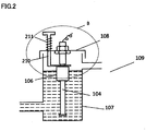
- Fig. 2 illustrates the structure of a liquid storage tank equipped with a liquid level monitoring device according to the present embodiment.
- the return member 211 is disposed outside a space surrounded by the tank body 107 and the cover member 108, a lower end thereof is in contact with the cover member 108, and an upper end thereof is in contact with the press member 210.
- the upper end of a portion of the press member 210 outside the tank body 107 is formed into a "T" shape.
- Fig. 2 illustrates that a part of the press member 210 is fitted in the return member 211
- the arrangement is not limited thereto, and as a modification, a part of the press member 210 may be disposed separately from the return member 211 such as that illustrated in Fig. 6(b) .
- the upper end of a portion of the press member 210 outside the space surrounded by the tank body 107 and the cover member 108 is not limited to the "T" shape, it may be a simple rod shape as illustrated in Fig. 1 .
- the upper end of the return member 211 needs to be fixed to the press member 210 so that when the press member 210 is pressed downward, the return member 211 is compressed to generate an upward return force, and in this case, a part of the press member 210 is preferably fitted in the return member 211.
- the return member 211 since the return member 211 is disposed outside the space surrounded by the tank body 107 and the cover member 108, the return member 211 may not be made of a chemical resistant material, and for example, it may be a metal spring.
- Fig. 3 illustrates the structure of a liquid storage tank equipped with a liquid level monitoring device according to the present embodiment.
- a side wall of the tank body 107 is provided with a through hole for the press member 310 to pass through.
- the return member 311 is disposed inside the tank body 107, and the upper end thereof may contact the press member 310 without being fixed, and the lower end thereof may be placed on or fixed to a support member 312 disposed on the side wall of the tank body 107.
- the support member 312 illustrated in Fig. 3 extends from the side wall of the tank body 107 in the horizontal direction but not limited to thereto, and it may have any shape as long as it can support the return member 311.
- Fig. 3 merely illustrates an example, and if the liquid level of the liquid in the tank body 107 is sufficiently low or if the return member 311 is sufficiently long, the return member 311 may be directly placed on or fixed to the bottom of the tank body 107.
- the through hole provided on the side wall of the tank body 107 serves as a fulcrum, and according to the lever principle, the portion of the press member 310 inside the tank body 107 is lowered to press the float member 106 below the liquid surface to a low liquid level, sending a low liquid level signal, and compress the return member 311 at the same time.
- the return member 311 generates an upward return force to return the portion of the press member 310 inside the tank body 107.
- the portion of the press member 310 inside the tank body 107 is returned by the return force to the initial position where the float member 106 is not pressed. Then, the float member 106 is also automatically returned to the high liquid level by the buoyant force and sends a high liquid level signal.
- Fig. 4 illustrates the structure of a liquid storage tank equipped with a liquid level monitoring device according to the present embodiment.
- the return member 411 is disposed outside the tank body 107, an upper end thereof is fixed to the press member 410, and a lower end is fixed to, for example, a support member 412 provided outside the tank body 107.
- the support member 412 may have any shape as long as it can support and fix the return member 411.
- Fig. 4 merely illustrates an example, and if the liquid level of the liquid in the tank body 107 is sufficiently low or if the length of the return member 411 is sufficiently long, the return member 411 may be directly fixed to the surface on which the tank body 107 is disposed.
- the through hole on the side wall of the tank body 107 serves as a fulcrum, and according to the lever principle, the portion of the press member 410 inside the tank body 107 is lowered to press the float member 106 below the liquid surface to a lower liquid level, sending a liquid level signal, and lengthen the return member 411 at the same time, which generates a downward return force to return the portion of the press member 410 outside the tank body 107.
- the portion of the press member 410 outside the tank body 107 is lowered by the return force, and according to the lever principle, the portion of the press member 410 inside the tank body 107 is returned to the initial position where the float member 106 is not pressed. Then, the float member 106 is also automatically returned to the high liquid level by the buoyant force and sends a high liquid level signal.
- the return member 411 since the return member 411 is disposed outside the tank body 107, the return member 411 may not be made of a chemical resistant material, and for example, it may be a metal spring.
Landscapes
- Physics & Mathematics (AREA)
- Fluid Mechanics (AREA)
- General Physics & Mathematics (AREA)
- Level Indicators Using A Float (AREA)
- Investigating Or Analysing Materials By Optical Means (AREA)
Abstract
Description
- The present invention relates to a liquid storage tank equipped with a liquid level monitoring device, and more particularly to a liquid storage tank to be used in an atomic absorption spectrophotometer.
- Atomic absorption spectrophotometers are widely used in various fields. For example,
Fig. 5 illustrates a partial structure of an atomic absorption spectrophotometer that is configured to detect elements according to a combustion method. InFig. 5 , thereference numeral 2 denotes a combustion head, the reference numeral 1 denotes a combustion flame, and thereference numeral 3 denotes a gas-liquid atomizing and mixing chamber. In order to prevent the occurrence of a safety accident such as an explosion caused by the returning of the flame 1 to the gas-liquid atomizing and mixing chamber 3 (also referred to as "backfire"), it is required to maintain the pressure in the gas-liquid atomizing and mixingchamber 3 at a constant pressure. As a common approach, a certain volume of liquid is sealed in acommunication pipe 5 and aliquid storage tank 9 that are in communication with the gas-liquid atomizing andmixing chamber 3 so as to maintain the gas-liquid atomizing and mixingchamber 3 at a relatively stable pressure. The liquid may be water or any other chemical liquid. - In order to ensure safety, it is required to monitor the pressure mentioned above. In other words, it is required to monitor the liquid level of the sealed liquid in real time while the spectrophotometer is operating. As a device for monitoring the liquid level, a float-type liquid level sensor may be adopted. As illustrated in
Fig. 5 , theliquid storage tank 9 includes atank body 7 that stores a liquid. The liquid level sensor mainly includes two parts: afloat member 6 and arod member 4. Therod member 4 is inserted into the liquid, and the float member (float) 6 is floating on the liquid surface of the liquid and can slide in the vertical direction along therod member 4 in accordance with a change in the liquid level of the liquid. Therod member 4 is fixed to a cover member (cover) 8 of the liquid storage tank. The liquid level is monitored by using sensor components built in thefloat member 6 and therod member 4 to monitor the position of thefloat member 6 relative to therod member 4 in real time. An electric signal indicating the liquid level is transmitted to a monitoring controller such as a computer via a transmission line (not shown). - Whether or not the float-type liquid level sensor mentioned above is working normally is directly related to the safe and stable operation of the spectrophotometer. Therefore, it is necessary to check whether or the liquid level sensor is working normally each time when the spectrophotometer is turned on to perform the self-checking operation (i.e., the self-checking operation of the liquid storage tank). During the self-checking operation, when the
float member 6 is brought to the lower end and the upper end of therod member 4, respectively, if the liquid level sensor outputs a low liquid level signal and a high liquid level signal correspondingly, it means that the liquid level sensor is working normally. - In the liquid storage tank according to the prior art illustrated in
Fig. 5 , during the self-checking operation, it is required that the operator disassembles theliquid storage tank 9 and lifts thecover member 8 and therod member 4 to move thefloat member 6 away from the liquid surface and then naturally drop it to the lowest position so as to obtain a liquid level signal (if the liquid level sensor is working normally, the liquid level signal indicates a low liquid level), and thereafter, the operator assembles thecover member 8 and therod member 4 into thetank body 7, and thefloat member 6 floats to the highest position by the buoyant force of the liquid so as to obtain another float level signal (if the liquid level sensor is working normally, the liquid level signal indicates a high liquid level). - When performing the self-checking operation, the operator needs to operate the
liquid storage tank 9 with one hand and operate the computer with the other hand. Specifically, the operator needs to disassemble and assemble theliquid storage tank 9 according to the instructions from the computer, and meanwhile needs to click buttons of a self-checking software executed on the computer, which makes the operation complicated. - In addition, even though the liquid in the
liquid storage tank 9 is water, the combustion of the flame 1 may produce a water-soluble toxic substance, which makes the liquid harmful to the human health. When performing the self-checking operation on theliquid storage tank 9, it is necessary to disassemble thecover member 8 and lift thecover member 8 and therod member 4, the operator may contact the liquid in theliquid storage tank 9, which may cause damage to the human health and pollution to the environment. - The present invention is made to solve the technical problems mentioned above, and an object thereof is to provide a liquid storage tank equipped with a liquid level monitoring device. The liquid storage tank includes a tank body that stores a liquid; a liquid level monitoring device that includes a rod member inserted into the liquid and a float member floating on a liquid surface of the liquid, wherein the liquid level monitoring device monitors the liquid level of the liquid in accordance with a sliding movement of the float member along the rod member in the vertical direction in response to a change in the liquid level of the liquid; a press member that extends from the outside of the tank body into the tank body and includes a portion outside the tank body and a portion inside the tank body, wherein the portion inside the tank body is in contact with the float member, and the press member presses the float member below the liquid surface of the liquid by using a pressing force applied from the outside of the liquid storage tank to the portion outside the tank body; and a return member, wherein one end of the return member is fixed to the press member, and when the press member presses the float member, the return member applies a return force to the press member so as to return the press member to an initial position where the float member is not pressed by the press member.
- Thus, the operator may complete the self-checking operation without disassembling or assembling the liquid storage tank. In addition, the liquid storage tank is simple in structure and high in reliability.
- The liquid storage tank equipped with the liquid level monitoring device according to a first embodiment of the present invention may further include a cover member disposed above the tank body, wherein the cover member is provided with a through hole for the press member to pass through, the return member is disposed inside a space surrounded by the tank body and the cover member, the one end of the return member is a lower end, and an upper end of the return member is fixed to the cover member.
- Therefore, the press member and the return member may be made simple in structure with few modifications to the original structure of the liquid storage tank and without increasing the volume in the circumferential direction of the liquid storage tank, and the return member may be appropriately protected by the tank body and the cover member.
- In this case, a part of the press member may be fitted in the return member, and a specific example thereof is illustrated in
Fig. 1 . In this case, the press member may support the return member and guide the movement of the return member. However, the present invention is not limited thereto. The press member may not be fitted in the return member, it may be disposed separately from the return member, and a specific example thereof is illustrated inFig. 6(a) . In this case, it is possible to prevent the press member and the return member from interfering with each other. - In the liquid storage tank equipped with the liquid level monitoring device according to a fourth embodiment of the present invention, it is acceptable that a side wall of the tank body is provided with a through hole for the press member to pass through, the return member is disposed outside the tank body, and the one end of the return member is an upper end, and a specific example thereof is illustrated in
Fig. 4 . - Therefore, the press member and the return member may be made simple in structure with few modifications to the original structure of the liquid storage tank and without increasing the volume in the height direction of the liquid storage tank, and the return member may be prevented from being corroded by the liquid in the tank body.
- The present invention further provides a liquid storage tank equipped with a liquid level monitoring device, and the liquid storage tank includes a tank body that stores a liquid; a liquid level monitoring device that includes a rod member inserted into the liquid and a float member floating on a liquid surface of the liquid, wherein the liquid level monitoring device monitors the liquid level of the liquid in accordance with a sliding movement of the float member along the rod member in the vertical direction in response to a change in the liquid level of the liquid; a press member that extends from the outside of the tank body into the tank body and includes a portion outside the tank body and a portion inside the tank body, wherein the portion inside the tank body is in contact with the float member, and the press member presses the float member below the liquid surface of the liquid by using a pressing force applied from the outside of the liquid storage tank to the portion outside the tank body; and a return member, wherein an upper end of the return member is in contact with the press member, and when the press member presses the float member, the return member applies a return force to the press member so as to return the press member to an initial position where the float member is not pressed by the press member.
- Thus, the operator may complete the self-checking operation without disassembling or assembling the liquid storage tank. In addition, the liquid storage tank is simple in structure and high in reliability.
- In the liquid storage tank equipped with the liquid level monitoring device according to a second embodiment of the present invention, it is acceptable that the liquid storage tank further includes a cover member disposed above the tank body, the cover member is provided with a through hole for the press member to pass through, the return member is disposed outside a space surrounded by the tank body and the cover member, and a lower end of the return member is in contact with the cover member.
- Therefore, the press member and the return member may be made simple in structure with few modifications to the original structure of the liquid storage tank and without increasing the volume in the circumferential direction of the liquid storage tank, and the return member may be prevented from being corroded by the liquid in the tank body.
- In this case, a part of the press member may be fitted in the return member, and a specific example thereof is illustrated in
Fig. 2 . In this case, the press member may support the return member and guide the movement of the return member. However, the present invention is not limited thereto. The press member may not be fitted in the return member, it may be disposed separately from the return member, and a specific example thereof is illustrated inFig. 6(b) . In this case, it is possible to prevent the press member and the return member from interfering with each other. - In the liquid storage tank provided with the liquid level monitoring device according to a third embodiment of the present invention, it is acceptable that a side wall of the tank body is provided with a through hole for the press member to pass through, and the return member is disposed inside the tank body. A specific example thereof is illustrated in
Fig. 3 . - Therefore, the press member and the return member may be made simple in structure with few modifications to the original structure of the liquid storage tank and without increasing the volume in the height direction of the liquid storage tank, and the return member may be appropriately protected by the tank body.
- In each of the above embodiments, the return member may be a coil spring or a leaf spring. Thereby, the return member is simple in structure and high in reliability.
- According to the liquid storage tank equipped with the liquid level monitoring device of the present invention, the operator may complete the self-checking operation of the liquid storage tank by pressing and releasing the press member without the need to disassemble and assemble the liquid storage tank, which makes it possible to reduce the work load of the operator and prevent the liquid containing the chemicals from causing any damage to the operator and the environment at the time of disassembling or assembling the liquid storage tank.
- The present invention is high in reliability since it is only necessary to add a press member and a return member that are simple in structure to the conventional liquid storage tank with few modifications to the original structure of the liquid storage tank. Thereby, the present invention is relatively low in cost and may be used to improve a conventional liquid storage tank on the market.
-
-
Fig. 1 is a schematic diagram illustrating the structure of a liquid storage tank equipped with a liquid level monitoring device according to a first embodiment; -
Fig. 2 is a schematic diagram illustrating the structure of a liquid storage tank equipped with a liquid level monitoring device according to a second embodiment; -
Fig. 3 is a schematic diagram illustrating the structure of a liquid storage tank equipped with a liquid level monitoring device according to a third embodiment; -
Fig. 4 is a schematic diagram illustrating the structure of a liquid storage tank equipped with a liquid level monitoring device according to a fourth embodiment; -
Fig. 5 is a schematic diagram illustrating the structure of a liquid storage tank in the prior art; -
Fig. 6(a) is a partial schematic diagram illustrating a modification of the first embodiment; and -
Fig. 6(b) is a partial schematic diagram illustrating a modification of the second embodiment. -
Fig. 1 illustrates the structure of a liquid storage tank equipped with a liquid level monitoring device according to the present embodiment. InFig. 1 , thereference numeral 102 denotes a combustion head, thereference numeral 101 denotes a combustion flame, and thereference numeral 103 denotes a gas-liquid atomizing and mixing chamber. - Similar to the prior art, a certain volume of liquid is sealed in a
communication pipe 105 and aliquid storage tank 109 that are in communication with the gas-liquid atomizing and mixingchamber 103. Theliquid storage tank 109 includes atank body 107 that is used to store a liquid. The liquid level sensor (that is, the liquid level monitoring device) mainly includes afloat member 106 and arod member 104. Therod member 104 is inserted into the liquid, and thefloat member 106 is floating on the liquid surface of the liquid and can slide in the vertical direction along therod member 104 in accordance with a change in the liquid level of the liquid. Thereby, the liquid level sensor monitors the liquid level of the liquid. An electric signal indicating the liquid level is transmitted to a monitoring controller such as a computer via a transmission line (not shown). - In the present embodiment, the
liquid storage tank 109 includes acover member 108 provided above thetank body 107. InFig. 1 , thecover member 108 and therod member 104 are fixed together. However, as long as the function of the liquid level sensor may be realized, the installation of therod member 104 is not limited to thereto, it may be fixed to the bottom of thetank body 107, for example. - In the present embodiment, the
liquid storage tank 109 is provided with apress member 110 and areturn member 111. Thepress member 110 extends from the outside of thetank body 107 into thetank body 107 via a through hole provided on thecover member 108, and a portion thereof inside thetank body 107 is in contact with thefloat member 106, and thepress member 110 presses thefloat member 106 below the liquid surface of the liquid by using a pressing force applied from the outside of the liquid storage tank (for example, applied by the operator) to a portion thereof outside the tank body. Thereturn member 111 may be, for example, a coil spring or a leaf spring, an upper end thereof is fixed to thecover member 108, and a lower end thereof is fixed to thepress member 110. As illustrated inFig. 1 , a part of thepress member 110 is fitted in thereturn member 111. - According to the liquid storage tank equipped with the liquid level monitoring device according to the present embodiment, at the time of verifying a low liquid level signal in the self-checking operation, the operator does not need to open the
cover member 108 and just needs to press thepress member 110 so as to move thepress member 110 downward, which lengthens thereturn member 111. Thepress member 110 overcomes a return force from thereturn member 111, and presses thefloat member 106 downward. If the liquid level sensor is working normally, the liquid level sensor sends a low liquid level signal. At the time of verifying a high liquid level signal, the operator may withdraw the force applied to thepress member 110. Thereby, thepress member 110 is returned by the return force to the initial position where thefloat member 106 is not pressed, and thefloat member 106 is automatically returned to a high liquid level by the buoyant force. If the liquid level sensor is working normally, the liquid level sensor sends a high liquid level signal. - Since the
press member 110 is required to contact the liquid in theliquid storage tank 109, thepress member 110 is preferably made of a chemical resistant material. In addition, since thereturn member 111 is disposed inside a space surrounded by thetank body 107 and thecover member 108, it may be corroded by the vaporized liquid in the space. Therefore, thereturn member 111 is preferably made of a chemical resistant material, and for example, it may be a plastic spring. AlthoughFig. 1 illustrates a case in which a part of thepress member 110 is fitted in thereturn member 111, the arrangement is not limited thereto, and as a modification, a part of thepress member 110 may be disposed separately from thereturn member 111 such as that illustrated inFig. 6(a) . - According to the above embodiment, the operator may complete the self-checking operation of the liquid storage tank by pressing and releasing the press member without the need to disassemble and assemble the liquid storage tank, which makes it possible to reduce the work load of the operator and prevent the liquid containing the chemicals from causing any damage to the operator and the environment at the time of disassembling or assembling the liquid storage tank.
-
Fig. 2 illustrates the structure of a liquid storage tank equipped with a liquid level monitoring device according to the present embodiment. As illustrated inFig. 2 , thereturn member 211 is disposed outside a space surrounded by thetank body 107 and thecover member 108, a lower end thereof is in contact with thecover member 108, and an upper end thereof is in contact with thepress member 210. As illustrated inFig. 2 , the upper end of a portion of thepress member 210 outside thetank body 107 is formed into a "T" shape. Thus, there is no need to fix thereturn member 211 to thepress member 210 and thecover member 108 as long as the upper end of thereturn member 211 is in contact with thepress member 210 and the lower end thereof is in contact with thecover member 108. When an external force is applied to press thepress member 210, thereturn member 211 is compressed by the T-shaped upper end so as to generate an upward return force. - Although
Fig. 2 illustrates that a part of thepress member 210 is fitted in thereturn member 211, the arrangement is not limited thereto, and as a modification, a part of thepress member 210 may be disposed separately from thereturn member 211 such as that illustrated inFig. 6(b) . - In addition, the upper end of a portion of the
press member 210 outside the space surrounded by thetank body 107 and thecover member 108 is not limited to the "T" shape, it may be a simple rod shape as illustrated inFig. 1 . In this case, the upper end of thereturn member 211 needs to be fixed to thepress member 210 so that when thepress member 210 is pressed downward, thereturn member 211 is compressed to generate an upward return force, and in this case, a part of thepress member 210 is preferably fitted in thereturn member 211. - Further, since the
return member 211 is disposed outside the space surrounded by thetank body 107 and thecover member 108, thereturn member 211 may not be made of a chemical resistant material, and for example, it may be a metal spring. - Other than that described in the above, the other parts of the present embodiment are the same as those of the first embodiment, and the description thereof will not be repeated.
-
Fig. 3 illustrates the structure of a liquid storage tank equipped with a liquid level monitoring device according to the present embodiment. As illustrated inFig. 3 , a side wall of thetank body 107 is provided with a through hole for thepress member 310 to pass through. Thereturn member 311 is disposed inside thetank body 107, and the upper end thereof may contact thepress member 310 without being fixed, and the lower end thereof may be placed on or fixed to asupport member 312 disposed on the side wall of thetank body 107. Thesupport member 312 illustrated inFig. 3 extends from the side wall of thetank body 107 in the horizontal direction but not limited to thereto, and it may have any shape as long as it can support thereturn member 311.Fig. 3 merely illustrates an example, and if the liquid level of the liquid in thetank body 107 is sufficiently low or if thereturn member 311 is sufficiently long, thereturn member 311 may be directly placed on or fixed to the bottom of thetank body 107. - When the portion of the
press member 310 outside thetank body 107 is lifted upward by the operator with an upward lifting force as illustrated by an arrow inFig. 3 , the through hole provided on the side wall of thetank body 107 serves as a fulcrum, and according to the lever principle, the portion of thepress member 310 inside thetank body 107 is lowered to press thefloat member 106 below the liquid surface to a low liquid level, sending a low liquid level signal, and compress thereturn member 311 at the same time. As a result, thereturn member 311 generates an upward return force to return the portion of thepress member 310 inside thetank body 107. On the other hand, when the operator withdraws the pressing force, the portion of thepress member 310 inside thetank body 107 is returned by the return force to the initial position where thefloat member 106 is not pressed. Then, thefloat member 106 is also automatically returned to the high liquid level by the buoyant force and sends a high liquid level signal. - Other than that described in the above, the other parts of the present embodiment are the same as those of the first embodiment, and the description thereof will not be repeated.
-
Fig. 4 illustrates the structure of a liquid storage tank equipped with a liquid level monitoring device according to the present embodiment. As illustrated inFig. 4 , thereturn member 411 is disposed outside thetank body 107, an upper end thereof is fixed to thepress member 410, and a lower end is fixed to, for example, asupport member 412 provided outside thetank body 107. Thesupport member 412 may have any shape as long as it can support and fix thereturn member 411.Fig. 4 merely illustrates an example, and if the liquid level of the liquid in thetank body 107 is sufficiently low or if the length of thereturn member 411 is sufficiently long, thereturn member 411 may be directly fixed to the surface on which thetank body 107 is disposed. - When the portion of the
press member 410 outside thetank body 107 is lifted upward by the operator with an upward lifting force as illustrated by an arrow inFig. 4 , the through hole on the side wall of thetank body 107 serves as a fulcrum, and according to the lever principle, the portion of thepress member 410 inside thetank body 107 is lowered to press thefloat member 106 below the liquid surface to a lower liquid level, sending a liquid level signal, and lengthen thereturn member 411 at the same time, which generates a downward return force to return the portion of thepress member 410 outside thetank body 107. On the other hand, when the operator withdraws the pressing force, the portion of thepress member 410 outside thetank body 107 is lowered by the return force, and according to the lever principle, the portion of thepress member 410 inside thetank body 107 is returned to the initial position where thefloat member 106 is not pressed. Then, thefloat member 106 is also automatically returned to the high liquid level by the buoyant force and sends a high liquid level signal. - In addition, since the
return member 411 is disposed outside thetank body 107, thereturn member 411 may not be made of a chemical resistant material, and for example, it may be a metal spring. - Other than that described in the above, the other parts of the present embodiment are the same as those of the third embodiment, and the description thereof will not be repeated.
- Although the embodiments of the present invention have been described above, the present invention is not limited to the above-described embodiments, and any technical solution that does not depart from the technical idea of the present invention is included within the scope of the claims of the present invention. In addition, the embodiments described above may be arbitrarily combined as long as they are not contradict to each other.
- 1, 101: flame; 2, 102: combustion head; 3, 103: gas-liquid atomizing and mixing chamber; 4, 104: rod member; 5, 105: communication pipe; 6, 106: float member; 7, 107: tank body; 8, 108: cover member; 9, 109: liquid storage tank; 110, 210, 310, 410: press member; 111, 211, 311, 411: return member; 312, 412: support member
Claims (10)
- A liquid storage tank equipped with a liquid level monitoring device, the liquid storage tank comprising:a tank body that stores a liquid;a liquid level monitoring device that includes a rod member inserted into the liquid and a float member floating on a liquid surface of the liquid, wherein the liquid level monitoring device monitors the liquid level of the liquid in accordance with a sliding movement of the float member along the rod member in the vertical direction in response to a change in the liquid level of the liquid;a press member that extends from the outside of the tank body into the tank body and includes a portion outside the tank body and a portion inside the tank body, wherein the portion inside the tank body is in contact with the float member, and the press member presses the float member below the liquid surface of the liquid by using a pressing force applied from the outside of the liquid storage tank to the portion outside the tank body; anda return member, wherein one end of the return member is fixed to the press member, and when the press member presses the float member, the return member applies a return force to the press member so as to return the press member to an initial position where the float member is not pressed by the press member.
- The liquid storage tank equipped with the liquid level monitoring device according to claim 1, further comprising a cover member disposed above the tank body, wherein
the cover member is provided with a through hole for the press member to pass through,
the return member is disposed inside a space surrounded by the tank body and the cover member,
the one end of the return member is a lower end, and
an upper end of the return member is fixed to the cover member. - The liquid storage tank equipped the liquid level monitoring device according to claim 2, wherein
a part of the press member is fitted in the return member. - The liquid storage tank equipped with the liquid level monitoring device according to claim 1, wherein
a side wall of the tank body is provided with a through hole for the press member to pass through,
the return member is disposed outside the tank body, and
the one end of the return member is an upper end. - The liquid storage tank equipped with the liquid level monitoring device according to any one of claims 1 to 4, wherein
the return member is a coil spring or a leaf spring. - A liquid storage tank equipped with a liquid level monitoring device, the liquid storage tank comprising:a tank body that stores a liquid;a liquid level monitoring device that includes a rod member inserted into the liquid and a float member floating on a liquid surface of the liquid, wherein the liquid level monitoring device monitors the liquid level of the liquid in accordance with a sliding movement of the float member along the rod member in the vertical direction in response to a change in the liquid level of the liquid;a press member that extends from the outside of the tank body into the tank body and includes a portion outside the tank body and a portion inside the tank body, wherein the portion inside the tank body is in contact with the float member, and the press member presses the float member below the liquid surface of the liquid by using a pressing force applied from the outside of the liquid storage tank to the portion outside the tank body; anda return member, wherein an upper end of the return member is in contact with the press member, and when the press member presses the float member, the return member applies a return force to the press member so as to return the press member to an initial position where the float member is not pressed by the press member.
- The liquid storage tank equipped with the liquid level monitoring device according to claim 6, further comprising a cover member disposed above the tank body, wherein
the cover member is provided with a through hole for the press member to pass through,
the return member is disposed outside a space surrounded by the tank body and the cover member, and
a lower end of the return member is in contact with the cover member. - The liquid storage tank equipped the liquid level monitoring device according to claim 7, wherein
a part of the press member is fitted in the return member. - The liquid storage tank equipped with the liquid level monitoring device according to claim 6, wherein
a side wall of the tank body is provided with a through hole for the press member to pass through, and
the return member is disposed inside the tank body. - The liquid storage tank equipped with the liquid level monitoring device according to any one of claims 6 to 9, wherein
the return member is a coil spring or a leaf spring.
Applications Claiming Priority (1)
| Application Number | Priority Date | Filing Date | Title |
|---|---|---|---|
| CN201920046275.7U CN209684489U (en) | 2019-01-11 | 2019-01-11 | Fluid storage tanks with level monitoring |
Publications (1)
| Publication Number | Publication Date |
|---|---|
| EP3680632A1 true EP3680632A1 (en) | 2020-07-15 |
Family
ID=68598582
Family Applications (1)
| Application Number | Title | Priority Date | Filing Date |
|---|---|---|---|
| EP19211369.4A Withdrawn EP3680632A1 (en) | 2019-01-11 | 2019-11-26 | Liquid storage tank equipped with liquid level monitoring device |
Country Status (3)
| Country | Link |
|---|---|
| EP (1) | EP3680632A1 (en) |
| JP (1) | JP2020112543A (en) |
| CN (1) | CN209684489U (en) |
Families Citing this family (1)
| Publication number | Priority date | Publication date | Assignee | Title |
|---|---|---|---|---|
| CN111157082B (en) * | 2019-12-18 | 2021-04-27 | 深圳市中科华工科技有限公司 | Water level switch calibration detector |
Citations (7)
| Publication number | Priority date | Publication date | Assignee | Title |
|---|---|---|---|---|
| GB1517280A (en) * | 1975-05-23 | 1978-07-12 | Richmond F | Liquid level warning apparatus |
| JPS5450590U (en) * | 1977-09-16 | 1979-04-07 | ||
| JPS55157069U (en) * | 1979-04-28 | 1980-11-12 | ||
| US4321590A (en) * | 1979-08-08 | 1982-03-23 | Toyota Jidosha Kogyo Kabushiki Kaisha | Check mechanism for fluid level warning device in fluid reservoirs |
| US4821022A (en) * | 1988-04-04 | 1989-04-11 | Jannotta Louis J | Float assembly checking system |
| WO2017039837A1 (en) * | 2015-09-01 | 2017-03-09 | Franklin Fueling Systems, Inc. | Tank maintenance access chamber |
| DE102016221435A1 (en) * | 2016-11-01 | 2018-05-03 | Continental Teves Ag & Co. Ohg | Warning device for a fluid container and method for testing the same |
Family Cites Families (4)
| Publication number | Priority date | Publication date | Assignee | Title |
|---|---|---|---|---|
| JPS58130228U (en) * | 1982-02-26 | 1983-09-02 | 株式会社東芝 | level meter |
| JPS6047923A (en) * | 1983-08-27 | 1985-03-15 | Nissan Motor Co Ltd | Reservior with liquid level detector |
| JP3139531B2 (en) * | 1995-09-22 | 2001-03-05 | 株式会社タツノ・メカトロニクス | Float type liquid level gauge |
| KR101503773B1 (en) * | 2013-12-31 | 2015-03-18 | 한국중부발전(주) | Level switch |
-
2019
- 2019-01-11 CN CN201920046275.7U patent/CN209684489U/en active Active
- 2019-11-08 JP JP2019203179A patent/JP2020112543A/en active Pending
- 2019-11-26 EP EP19211369.4A patent/EP3680632A1/en not_active Withdrawn
Patent Citations (7)
| Publication number | Priority date | Publication date | Assignee | Title |
|---|---|---|---|---|
| GB1517280A (en) * | 1975-05-23 | 1978-07-12 | Richmond F | Liquid level warning apparatus |
| JPS5450590U (en) * | 1977-09-16 | 1979-04-07 | ||
| JPS55157069U (en) * | 1979-04-28 | 1980-11-12 | ||
| US4321590A (en) * | 1979-08-08 | 1982-03-23 | Toyota Jidosha Kogyo Kabushiki Kaisha | Check mechanism for fluid level warning device in fluid reservoirs |
| US4821022A (en) * | 1988-04-04 | 1989-04-11 | Jannotta Louis J | Float assembly checking system |
| WO2017039837A1 (en) * | 2015-09-01 | 2017-03-09 | Franklin Fueling Systems, Inc. | Tank maintenance access chamber |
| DE102016221435A1 (en) * | 2016-11-01 | 2018-05-03 | Continental Teves Ag & Co. Ohg | Warning device for a fluid container and method for testing the same |
Also Published As
| Publication number | Publication date |
|---|---|
| JP2020112543A (en) | 2020-07-27 |
| CN209684489U (en) | 2019-11-26 |
Similar Documents
| Publication | Publication Date | Title |
|---|---|---|
| US11740251B2 (en) | Sensor interrogation | |
| US11740201B2 (en) | Sensor interrogation | |
| US10451581B2 (en) | Sensor interrogation | |
| EP2972277B1 (en) | Gas sensor interrogation | |
| US9528957B2 (en) | Sensor interrogation | |
| EP3680632A1 (en) | Liquid storage tank equipped with liquid level monitoring device | |
| US20070205907A1 (en) | Switch assembly and system for high-level monitoring | |
| US20180156249A1 (en) | Cylinder device | |
| EP2954294B1 (en) | Displacement level sensor and seal and pivot assembly for displacement level sensor | |
| JP4313289B2 (en) | Fuel tank pump module structure | |
| KR101610478B1 (en) | Overflow discharge apparatus for tank-lorry | |
| EP1343680A1 (en) | Vacuum relief unit with means preventing the effects of an accident | |
| EP1818656A3 (en) | Oil level detection device for internal combustion engine | |
| EP1970611A1 (en) | Liquid pressure-feed device | |
| US11454254B2 (en) | State determination device of liquid pumping apparatus, and liquid pumping apparatus | |
| CN210072100U (en) | Press-riveting leak-proof indirect detection mechanism | |
| CN213592205U (en) | Foam pump seal gasket detection mechanism | |
| CN223105816U (en) | A gas-liquid actuator testing device | |
| JP7327590B2 (en) | atomic absorption spectrophotometer | |
| CN110936651A (en) | Compressor for industrial waste iron drum | |
| CN204792316U (en) | Sealed transformer oil position compensation arrangement | |
| CN209542344U (en) | A pressure adjustment system of a friction sensitivity tester | |
| US2749401A (en) | Oil safety measuring rod | |
| CN111717830B (en) | Lifting device capable of lifting stably | |
| CN110044444A (en) | A kind of float level meter test device |
Legal Events
| Date | Code | Title | Description |
|---|---|---|---|
| PUAI | Public reference made under article 153(3) epc to a published international application that has entered the european phase |
Free format text: ORIGINAL CODE: 0009012 |
|
| STAA | Information on the status of an ep patent application or granted ep patent |
Free format text: STATUS: REQUEST FOR EXAMINATION WAS MADE |
|
| 17P | Request for examination filed |
Effective date: 20191128 |
|
| AK | Designated contracting states |
Kind code of ref document: A1 Designated state(s): AL AT BE BG CH CY CZ DE DK EE ES FI FR GB GR HR HU IE IS IT LI LT LU LV MC MK MT NL NO PL PT RO RS SE SI SK SM TR |
|
| AX | Request for extension of the european patent |
Extension state: BA ME |
|
| RBV | Designated contracting states (corrected) |
Designated state(s): AL AT BE BG CH CY CZ DE DK EE ES FI FR GB GR HR HU IE IS IT LI LT LU LV MC MK MT NL NO PL PT RO RS SE SI SK SM TR |
|
| STAA | Information on the status of an ep patent application or granted ep patent |
Free format text: STATUS: EXAMINATION IS IN PROGRESS |
|
| 17Q | First examination report despatched |
Effective date: 20210803 |
|
| STAA | Information on the status of an ep patent application or granted ep patent |
Free format text: STATUS: THE APPLICATION HAS BEEN WITHDRAWN |
|
| 18W | Application withdrawn |
Effective date: 20211203 |