EP3680589A1 - Refrigerator - Google Patents
Refrigerator Download PDFInfo
- Publication number
- EP3680589A1 EP3680589A1 EP20150245.7A EP20150245A EP3680589A1 EP 3680589 A1 EP3680589 A1 EP 3680589A1 EP 20150245 A EP20150245 A EP 20150245A EP 3680589 A1 EP3680589 A1 EP 3680589A1
- Authority
- EP
- European Patent Office
- Prior art keywords
- fan
- storage space
- space
- storage chamber
- refrigerator
- Prior art date
- Legal status (The legal status is an assumption and is not a legal conclusion. Google has not performed a legal analysis and makes no representation as to the accuracy of the status listed.)
- Granted
Links
Images






Classifications
-
- F—MECHANICAL ENGINEERING; LIGHTING; HEATING; WEAPONS; BLASTING
- F25—REFRIGERATION OR COOLING; COMBINED HEATING AND REFRIGERATION SYSTEMS; HEAT PUMP SYSTEMS; MANUFACTURE OR STORAGE OF ICE; LIQUEFACTION SOLIDIFICATION OF GASES
- F25D—REFRIGERATORS; COLD ROOMS; ICE-BOXES; COOLING OR FREEZING APPARATUS NOT OTHERWISE PROVIDED FOR
- F25D11/00—Self-contained movable devices, e.g. domestic refrigerators
- F25D11/02—Self-contained movable devices, e.g. domestic refrigerators with cooling compartments at different temperatures
- F25D11/025—Self-contained movable devices, e.g. domestic refrigerators with cooling compartments at different temperatures using primary and secondary refrigeration systems
-
- F—MECHANICAL ENGINEERING; LIGHTING; HEATING; WEAPONS; BLASTING
- F25—REFRIGERATION OR COOLING; COMBINED HEATING AND REFRIGERATION SYSTEMS; HEAT PUMP SYSTEMS; MANUFACTURE OR STORAGE OF ICE; LIQUEFACTION SOLIDIFICATION OF GASES
- F25D—REFRIGERATORS; COLD ROOMS; ICE-BOXES; COOLING OR FREEZING APPARATUS NOT OTHERWISE PROVIDED FOR
- F25D17/00—Arrangements for circulating cooling fluids; Arrangements for circulating gas, e.g. air, within refrigerated spaces
- F25D17/04—Arrangements for circulating cooling fluids; Arrangements for circulating gas, e.g. air, within refrigerated spaces for circulating air, e.g. by convection
- F25D17/06—Arrangements for circulating cooling fluids; Arrangements for circulating gas, e.g. air, within refrigerated spaces for circulating air, e.g. by convection by forced circulation
-
- F—MECHANICAL ENGINEERING; LIGHTING; HEATING; WEAPONS; BLASTING
- F25—REFRIGERATION OR COOLING; COMBINED HEATING AND REFRIGERATION SYSTEMS; HEAT PUMP SYSTEMS; MANUFACTURE OR STORAGE OF ICE; LIQUEFACTION SOLIDIFICATION OF GASES
- F25D—REFRIGERATORS; COLD ROOMS; ICE-BOXES; COOLING OR FREEZING APPARATUS NOT OTHERWISE PROVIDED FOR
- F25D29/00—Arrangement or mounting of control or safety devices
-
- F—MECHANICAL ENGINEERING; LIGHTING; HEATING; WEAPONS; BLASTING
- F25—REFRIGERATION OR COOLING; COMBINED HEATING AND REFRIGERATION SYSTEMS; HEAT PUMP SYSTEMS; MANUFACTURE OR STORAGE OF ICE; LIQUEFACTION SOLIDIFICATION OF GASES
- F25D—REFRIGERATORS; COLD ROOMS; ICE-BOXES; COOLING OR FREEZING APPARATUS NOT OTHERWISE PROVIDED FOR
- F25D17/00—Arrangements for circulating cooling fluids; Arrangements for circulating gas, e.g. air, within refrigerated spaces
- F25D17/04—Arrangements for circulating cooling fluids; Arrangements for circulating gas, e.g. air, within refrigerated spaces for circulating air, e.g. by convection
- F25D17/042—Air treating means within refrigerated spaces
-
- F—MECHANICAL ENGINEERING; LIGHTING; HEATING; WEAPONS; BLASTING
- F25—REFRIGERATION OR COOLING; COMBINED HEATING AND REFRIGERATION SYSTEMS; HEAT PUMP SYSTEMS; MANUFACTURE OR STORAGE OF ICE; LIQUEFACTION SOLIDIFICATION OF GASES
- F25D—REFRIGERATORS; COLD ROOMS; ICE-BOXES; COOLING OR FREEZING APPARATUS NOT OTHERWISE PROVIDED FOR
- F25D17/00—Arrangements for circulating cooling fluids; Arrangements for circulating gas, e.g. air, within refrigerated spaces
- F25D17/04—Arrangements for circulating cooling fluids; Arrangements for circulating gas, e.g. air, within refrigerated spaces for circulating air, e.g. by convection
- F25D17/042—Air treating means within refrigerated spaces
- F25D17/045—Air flow control arrangements
-
- F—MECHANICAL ENGINEERING; LIGHTING; HEATING; WEAPONS; BLASTING
- F25—REFRIGERATION OR COOLING; COMBINED HEATING AND REFRIGERATION SYSTEMS; HEAT PUMP SYSTEMS; MANUFACTURE OR STORAGE OF ICE; LIQUEFACTION SOLIDIFICATION OF GASES
- F25D—REFRIGERATORS; COLD ROOMS; ICE-BOXES; COOLING OR FREEZING APPARATUS NOT OTHERWISE PROVIDED FOR
- F25D17/00—Arrangements for circulating cooling fluids; Arrangements for circulating gas, e.g. air, within refrigerated spaces
- F25D17/04—Arrangements for circulating cooling fluids; Arrangements for circulating gas, e.g. air, within refrigerated spaces for circulating air, e.g. by convection
- F25D17/06—Arrangements for circulating cooling fluids; Arrangements for circulating gas, e.g. air, within refrigerated spaces for circulating air, e.g. by convection by forced circulation
- F25D17/062—Arrangements for circulating cooling fluids; Arrangements for circulating gas, e.g. air, within refrigerated spaces for circulating air, e.g. by convection by forced circulation in household refrigerators
- F25D17/065—Arrangements for circulating cooling fluids; Arrangements for circulating gas, e.g. air, within refrigerated spaces for circulating air, e.g. by convection by forced circulation in household refrigerators with compartments at different temperatures
-
- F—MECHANICAL ENGINEERING; LIGHTING; HEATING; WEAPONS; BLASTING
- F25—REFRIGERATION OR COOLING; COMBINED HEATING AND REFRIGERATION SYSTEMS; HEAT PUMP SYSTEMS; MANUFACTURE OR STORAGE OF ICE; LIQUEFACTION SOLIDIFICATION OF GASES
- F25D—REFRIGERATORS; COLD ROOMS; ICE-BOXES; COOLING OR FREEZING APPARATUS NOT OTHERWISE PROVIDED FOR
- F25D17/00—Arrangements for circulating cooling fluids; Arrangements for circulating gas, e.g. air, within refrigerated spaces
- F25D17/04—Arrangements for circulating cooling fluids; Arrangements for circulating gas, e.g. air, within refrigerated spaces for circulating air, e.g. by convection
- F25D17/06—Arrangements for circulating cooling fluids; Arrangements for circulating gas, e.g. air, within refrigerated spaces for circulating air, e.g. by convection by forced circulation
- F25D17/067—Evaporator fan units
-
- F—MECHANICAL ENGINEERING; LIGHTING; HEATING; WEAPONS; BLASTING
- F25—REFRIGERATION OR COOLING; COMBINED HEATING AND REFRIGERATION SYSTEMS; HEAT PUMP SYSTEMS; MANUFACTURE OR STORAGE OF ICE; LIQUEFACTION SOLIDIFICATION OF GASES
- F25D—REFRIGERATORS; COLD ROOMS; ICE-BOXES; COOLING OR FREEZING APPARATUS NOT OTHERWISE PROVIDED FOR
- F25D19/00—Arrangement or mounting of refrigeration units with respect to devices or objects to be refrigerated, e.g. infrared detectors
- F25D19/04—Arrangement or mounting of refrigeration units with respect to devices or objects to be refrigerated, e.g. infrared detectors with more than one refrigeration unit
-
- F—MECHANICAL ENGINEERING; LIGHTING; HEATING; WEAPONS; BLASTING
- F25—REFRIGERATION OR COOLING; COMBINED HEATING AND REFRIGERATION SYSTEMS; HEAT PUMP SYSTEMS; MANUFACTURE OR STORAGE OF ICE; LIQUEFACTION SOLIDIFICATION OF GASES
- F25D—REFRIGERATORS; COLD ROOMS; ICE-BOXES; COOLING OR FREEZING APPARATUS NOT OTHERWISE PROVIDED FOR
- F25D31/00—Other cooling or freezing apparatus
- F25D31/005—Combined cooling and heating devices
-
- F—MECHANICAL ENGINEERING; LIGHTING; HEATING; WEAPONS; BLASTING
- F25—REFRIGERATION OR COOLING; COMBINED HEATING AND REFRIGERATION SYSTEMS; HEAT PUMP SYSTEMS; MANUFACTURE OR STORAGE OF ICE; LIQUEFACTION SOLIDIFICATION OF GASES
- F25D—REFRIGERATORS; COLD ROOMS; ICE-BOXES; COOLING OR FREEZING APPARATUS NOT OTHERWISE PROVIDED FOR
- F25D2317/00—Details or arrangements for circulating cooling fluids; Details or arrangements for circulating gas, e.g. air, within refrigerated spaces, not provided for in other groups of this subclass
- F25D2317/04—Treating air flowing to refrigeration compartments
- F25D2317/041—Treating air flowing to refrigeration compartments by purification
- F25D2317/0413—Treating air flowing to refrigeration compartments by purification by humidification
-
- F—MECHANICAL ENGINEERING; LIGHTING; HEATING; WEAPONS; BLASTING
- F25—REFRIGERATION OR COOLING; COMBINED HEATING AND REFRIGERATION SYSTEMS; HEAT PUMP SYSTEMS; MANUFACTURE OR STORAGE OF ICE; LIQUEFACTION SOLIDIFICATION OF GASES
- F25D—REFRIGERATORS; COLD ROOMS; ICE-BOXES; COOLING OR FREEZING APPARATUS NOT OTHERWISE PROVIDED FOR
- F25D2317/00—Details or arrangements for circulating cooling fluids; Details or arrangements for circulating gas, e.g. air, within refrigerated spaces, not provided for in other groups of this subclass
- F25D2317/04—Treating air flowing to refrigeration compartments
- F25D2317/041—Treating air flowing to refrigeration compartments by purification
- F25D2317/0413—Treating air flowing to refrigeration compartments by purification by humidification
- F25D2317/04131—Control means therefor
-
- F—MECHANICAL ENGINEERING; LIGHTING; HEATING; WEAPONS; BLASTING
- F25—REFRIGERATION OR COOLING; COMBINED HEATING AND REFRIGERATION SYSTEMS; HEAT PUMP SYSTEMS; MANUFACTURE OR STORAGE OF ICE; LIQUEFACTION SOLIDIFICATION OF GASES
- F25D—REFRIGERATORS; COLD ROOMS; ICE-BOXES; COOLING OR FREEZING APPARATUS NOT OTHERWISE PROVIDED FOR
- F25D2400/00—General features of, or devices for refrigerators, cold rooms, ice-boxes, or for cooling or freezing apparatus not covered by any other subclass
- F25D2400/02—Refrigerators including a heater
-
- F—MECHANICAL ENGINEERING; LIGHTING; HEATING; WEAPONS; BLASTING
- F25—REFRIGERATION OR COOLING; COMBINED HEATING AND REFRIGERATION SYSTEMS; HEAT PUMP SYSTEMS; MANUFACTURE OR STORAGE OF ICE; LIQUEFACTION SOLIDIFICATION OF GASES
- F25D—REFRIGERATORS; COLD ROOMS; ICE-BOXES; COOLING OR FREEZING APPARATUS NOT OTHERWISE PROVIDED FOR
- F25D2600/00—Control issues
- F25D2600/06—Controlling according to a predetermined profile
-
- F—MECHANICAL ENGINEERING; LIGHTING; HEATING; WEAPONS; BLASTING
- F25—REFRIGERATION OR COOLING; COMBINED HEATING AND REFRIGERATION SYSTEMS; HEAT PUMP SYSTEMS; MANUFACTURE OR STORAGE OF ICE; LIQUEFACTION SOLIDIFICATION OF GASES
- F25D—REFRIGERATORS; COLD ROOMS; ICE-BOXES; COOLING OR FREEZING APPARATUS NOT OTHERWISE PROVIDED FOR
- F25D2700/00—Means for sensing or measuring; Sensors therefor
- F25D2700/02—Sensors detecting door opening
Definitions
- the controller may drive the fan to increase humidity in the storage space when the door is closed, the refrigeration system is not operated to cool the storage space, and the heater is in a power off state.
- the controller may close the first damper and open the second damper during the second portion of the time period when driving the fan to increase humidity in the storage space even when a temperature in the first space is outside at a target range associated with the target temperature of the first space.
- the controller may not drive the fan when the heater is operated to heat the refrigeration space.
- the refrigerator may perform a specific operation for the priority storage chamber and a specific operation for the subordinate storage chamber.
- the specific operation includes a general operation and a special operation for the storage chamber.
- a general operation may include, for example, a conventional cooling operation for the storage chamber cooling.
- the special operation may include, for example, a defrost operation for defrosting the cooling device, a door load response operation that can be performed when one or more predetermined conditions are satisfied after the door is opened, or an initial power supply operation, which is an operation when the power is first supplied to the refrigerator.
- the refrigerator may include cooling device and heating device for controlling the temperature of at least one storage chamber among a specific goods storage chamber, a constant temperature chamber, and a priority storage chamber.
- the refrigerator may perform a cooling operation E in which the storage chamber W is cooled by the cooling device(s) or a heating operation H in which the storage chamber W is heated by the heating device(s), for temperature control of the storage chamber W.
- the refrigerator may implement a standby mode D that maintains the storage chamber W in a current state without cooling or heating.
- the refrigerator may include a temperature sensor for sensing a temperature of the storage chamber W and may perform the cooling operation E, the heating operation H, and the standby mode D according to the storage chamber temperature sensed by the temperature sensor.
- the refrigerator may include a see-through door.
- the see-through door may be a door that can selectively switched between a first state in which the door is at least partially transparent and a user can see through the door (a see-through activation state), and a second state in which the door is at least partially opaque and a user cannot see through the door (a see-through deactivation state).
- the see-through door may be a door that is changed from a see-through deactivation state to a see-through activation state or is changed from a see-through activation state to a see-through deactivation state according to an input value provided to the controller 30 through the input device.
- the see-through door may be a door in which the see-through door is changed from see-through deactivation state to see-through activation state when the see-through door is closed and according to an input value provided to the controller 30 through the input device.
- the outer door 22 may be opaque, and an opening portion 21 may be formed in (e.g., in a central region) of the outer door 22.
- the outer door 22 may form an outer appearance of the see-through door.
- the outer door 22 may be rotatably connected to or connected to the cabinet 1 to be capable of being advanced and retracted to open storage chamber W.
- the panel assembly 23 may be disposed in the opening portion 21.
- the panel assembly 23 may be disposed to shield the opening portion 21.
- the panel assembly 23 can form the same outer appearance as the front surface of the outer door 22.
- FIG. 12 is a sectional view when another example of a door according to an embodiment of the present disclosure is opened by a door opening module 11'.
- the door is drawer that may be automatically opened by the door opening module 11' that applies an outward force.
- the temperature adjusting device disposed in the refrigerant flow path P will be described as an example of cooling device(s), but the temperature adjusting device disposed in the air flow path P is not limited to being a cooling device(s), but may be a heating device such as a heater.
- the temperature adjusting device disposed in the air flow path P is not limited to being a cooling device(s), but may be a heating device such as a heater.
- the evaporator which can be an example for the temperature adjusting device disposed in the air flow path P.
- the refrigerator may include a guide 234 for guiding air forced by the fan 181 inside the air guide 400 to the outlet 412.
- the guide 234 may be formed in the discharge guide 202 to guide the air blown from the fan 181 to the outlet 412.
- the air guide 400 may be provided with a scroll 413 and an opening portion 414 for guiding air to the discharge flow path P2.
- the scroll 413 may guide the air blown from the fan 181 to the opening portion 414.
- the opening portion 414 may communicate with the lower end of the discharge flow path P2.
- the controller 30 may operate or stop the temperature adjusting device 150.
- the operation of the temperature adjusting device 150 may mean that the refrigerant flows to the temperature adjusting device 150, and for example, may be a case where the compressor 100 is on and the refrigerant valve is in the evaporator mode which supplies refrigerant to the evaporator.
- the stop of the temperature adjusting device 150 may mean that the refrigerant does not flow to the temperature adjusting device 150, and for example, a mode in which the refrigerant valve does not supply the refrigerant to the evaporator (for example, a mode for supplying a refrigerant to a second evaporator, or the like).
- the number of rotations or on-time period (duty cycle) of the fan for the cooling device(s) during the humidity care mode driving may be controlled so that the relative humidity (RH) average of the storage chamber is over 50% RH.
- the fan speed or on-time period (duty cycle) for cooling device(s) during humidity care mode driving is controlled so that the relative humidity average of the storage chamber is 50% to 75% (European standard).
- the operation of the temperature adjusting device (or cooler) 150 may relate to controlling the cooling the storage space, and the operation of the heating device (or heater) may relate to controlling the heating the storage space.
- the humidity management of the storage space may be important for the previously described reasons, but in order to ensure constant temperature properties, the temperature management of the storage chamber may be more important, and the controller 30 may perform the humidity care mode in a lower order of importance than controlling the cooling of the storage space (that is, the cooling operation) or the controlling the heating of the storage space (that is, heating operation).
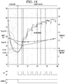
- Region (d) of Fig. 17 illustrates an example in which a fan 181 for flowing air in the first storage chamber W is turned on all when the first storage chamber W is cooled, when the second storage chamber C is cooled, and when the compressor 100 is turned off.
- the speed of the fan 181 when the second storage chamber C is cooled or the speed of the fan 181 when the compressor 100 is turned off may be slower than the speed of fan 181 when the first storage chamber C is cooled.
- the fan 181 is controlled as illustrated in Fig. 17(d) , the effect of increasing the humidity of the storage space by turning on the fan 181 may be high, and the refrigerator may maintain the storage space at a high relative humidity as a whole.
- the controller 30 can compare the elapsed time with a first set time (for example, 8 minutes) after the fan 181 is off, and if the time elapsed is equal to or less than the first set time after the fan 181 is off, the controller 30 can maintain the off state of the fan 181 for a second set time (for example, 2 minutes), and may wait without controlling each of the first and second dampers 191 and 192 in the open mode (S1)(S2)(S3)(S5)(S6).
- a first set time for example, 8 minutes
- the controller 30 can maintain the off state of the fan 181 for a second set time (for example, 2 minutes), and may wait without controlling each of the first and second dampers 191 and 192 in the open mode (S1)(S2)(S3)(S5)(S6).
- the controller may end the humidity care mode if the cooling operation is ended or the storage space is opened during the humidity care mode.
- the controller may resume the humidity care mode if the cooling operation is performed, the door that opens and closes the storage space is closed, and the cold mode is not performed after the humidity care mode is ended.
- the refrigerator may further include a heating device configured to heat the storage space.
- the controller may not perform the humidity care mode if the heating operation for heating the storage space by the heating device is performed.
Landscapes
- Engineering & Computer Science (AREA)
- Chemical & Material Sciences (AREA)
- Combustion & Propulsion (AREA)
- Physics & Mathematics (AREA)
- Mechanical Engineering (AREA)
- Thermal Sciences (AREA)
- General Engineering & Computer Science (AREA)
- Devices That Are Associated With Refrigeration Equipment (AREA)
- Cold Air Circulating Systems And Constructional Details In Refrigerators (AREA)
Abstract
Description
- The present disclosure relates to a refrigerator.
- In general, a refrigerator is an appliance that allows food or other items to be stored at a relatively low temperature in an internal storage space that is accessed by a door. The refrigerator may cool the inside of the storage space by using air heat exchanged with the refrigerant circulating in a refrigeration cycle such that stored food, cosmetics, or the like (hereinafter, referred to as goods) may be in an optimal state. For example, the refrigerator may condense moisture in the air in the storage chamber by a heat exchanging device such as an evaporator such that the storage chamber may have relatively lower humidity than the outside of the refrigerator. Some of the goods stored in a refrigerator may be optimally stored at an appropriate humidity, and for this purpose, a refrigerator may include a component to adjust the humidity of the storage chamber.
- An example of a refrigerator having a humidity adjuster is a temperature and humidity adjusted wine refrigerator discussed in Korean Utility Model Publication No.
20-0380906 Y1 (published March 29, 2005 - In another example, a refrigerator may be formed to include a separate outside air suction passage such that the air outside the refrigerator can flow into the storage chamber to provide additional humidity to the storage chamber. However, the cooled air in the storage chamber may be exhausted through the outside air suction passage, causing a potentially large heat loss, and potentially allowing foreign matter, such as dust, to penetrate the storage chamber through the outside air suction passage.
- The above reference is incorporated by reference herein where appropriate for appropriate teachings of additional or alternative details, features and/or technical background.
- An object of the present invention is to provide a refrigerator having an improved humidity control.
- The object is solved by the features of the independent claims. Preferred embodiments are given in the dependent claims.
- According to one aspect a refrigerator is provided comprising: a cabinet configured to form a storage space; a door that opens and closes the storage space; a refrigeration system to cool the storage space, the refrigeration system including a fan that blows air between the refrigeration system and the storage space; and a controller configured to control the fan, wherein the controller drives the fan to increase humidity in the storage space when the door is closed and the refrigeration system is not operated to cool the storage space.
- Preferably, the refrigerator may further comprise a heater to heat the storage space.
- Preferably, the refrigerator may further comprise a damper that is configured to be opened and closed to adjust air flowing into the storage space.
- Preferably, the controller may drive the fan to increase humidity in the storage space when the door is closed, the refrigeration system is not operated to cool the storage space, and the heater is in a power off state.
- Preferably, the controller may drive the fan for a predetermined time and may open the damper to increase humidity in the storage space when the door is closed and the refrigeration system is not operated to cool the storage space.
- Preferably, the controller may pause driving the fan to increase humidity in the storage space when the door is opened or the refrigeration system is operated to cool the storage space, or a heater is in a power-on state to heat the storage space.
- Preferably, the controller may, after pausing the driving of the fan to increase humidity in the storage space, resume driving the fan to increase humidity in the storage space when the door is closed, the refrigeration system is not operated to cool the storage space, and the heating device is in a power-off state.
- Preferably, the storage space may include a first storage space and second storage space.
- Preferably, the first storage space may have a first fan and the second storage space may have the second fan.
- Preferably, the refrigeration system may include a first refrigeration system for controlling temperature of the first storage space having a first target temperature and a second refrigeration system for controlling temperature of the second storage space.
- Preferably, the second storage space may be partitioned from the first storage space.
- Preferably, the second storage space may be associated with a second target temperature that is lower than the first target temperature.
- Preferably, the refrigerator may further comprise a second refrigeration system which cools the second storage space, the second refrigeration system including a second fan that blows air between the second refrigeration system and the second storage space.
- Preferably, the controller may delay driving the first fan to increase humidity in the first storage space when the second refrigeration system is being defrosted.
- Preferably, the controller may delay driving the fan to increase humidity in the storage space when the humidity of the refrigeration space is equal to or greater than a set humidity level.
- Preferably, the controller may stop driving the fan to increase humidity in the storage space when the humidity of the refrigeration space is equal to or greater than a set humidity level.
- Preferably, the storage space may be a refrigeration space which is partitioned into a first space and a second space, wherein the fan blows air into the first space and the second space.
- Preferably, the refrigerator may further comprises a first damper that can be opened and can be closed to adjust a flow of air from the refrigeration system into the first space.
- Preferably, the refrigerator may further comprises a second damper that can be opened and closed to adjust a flow of air from the refrigeration system into the second space.
- Preferably, the controller may open the first damper and close the second damper during a first portion of a time period when driving the fan to increase humidity in the storage space.
- Preferably, the controller may close the first damper and open the second damper during a second portion of the time period when driving the fan to increase humidity in the storage space.
- Preferably, a target temperature of the first space may be higher than a target temperature of the second space.
- Preferably, the controller may close the first damper and open the second damper during the second portion of the time period when driving the fan to increase humidity in the storage space even when a temperature in the first space is outside at a target range associated with the target temperature of the first space.
- Preferably, the controller may determine that the refrigeration system is not operated to cool the storage chamber when refrigerant stops flowing to an evaporator of the refrigeration system.
- Preferably, the controller may delay driving the fan to increase humidity in the storage space after a set time has elapsed after refrigerant stops flowing to the evaporator of the refrigeration system.
- Preferably, the controller may, when controlling the fan, drive the fan to blow a first volume of air when the refrigeration system is operated to cool the refrigeration space.
- Preferably, the controller may drive, when the door is closed and the refrigeration system is not operated to cool the refrigeration space, the fan to blow a second volume of air to increase humidity in the refrigeration space.
- Preferably, the first air volume is greater than the second air volume.
- Preferably, the controller may pause driving the fan to blow the second volume of air when the door is opened or the refrigeration system is operated to cool the refrigeration space.
- Preferably, the controller may resume driving the fan to blow the second volume of air when the door is closed and the refrigeration system is not operated to cool the refrigeration space.
- Preferably, the refrigerator may further comprise a heater configured to heat the refrigeration space.
- Preferably, the controller may not drive the fan when the heater is operated to heat the refrigeration space.
- Embodiments will be described in detail with reference to the following drawings in which like reference numerals refer to like elements, and wherein:
-
Fig. 1 is a sectional view illustrating an example of a refrigerator according to an embodiment of the present disclosure; -
Fig. 2 is a sectional view illustrating another example of a refrigerator according to an embodiment of the present disclosure; -
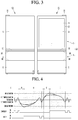
Fig. 3 is a front view when a refrigerator according to an embodiment of the present disclosure is disposed adjacent to another refrigerator; -
Fig. 4 is a view illustrating on and off of cooling device(s) and on and off of heating device(s) according to the temperature change of the storage chamber according to an embodiment of the present disclosure; -
Figs. 5 to 8 are views illustrating examples of a refrigeration cycle of a refrigerator according to an embodiment of the present disclosure; -
Fig. 9 is a control block diagram of a refrigerator of an embodiment of the present disclosure; -
Fig. 10 is a perspective view illustrating a see-through door of a refrigerator according to an embodiment of the present disclosure; -
Fig. 11 is a plan view when an example of a door according to an embodiment of the present disclosure is opened in a door opening module; -
Fig. 12 is a cross-sectional view when another example of a door according to an embodiment of the present disclosure is opened by the door opening module; -
Fig. 13 is a sectional view when a holder illustrated inFig. 12 is lifted; -
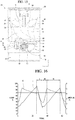
Fig. 14 is a front view illustrating a storage chamber of a refrigerator according to an embodiment of the present disclosure; -
Fig. 15 is a rear view illustrating an inner portion of the inner guide according to an embodiment of the present disclosure; -
Fig. 16 is a view showing a change in storage chamber temperature and storage chamber humidity in the cooling mode of the storage chamber according to an embodiment of the present disclosure; -
Fig. 17 is a view illustrating a compressor operation and a fan operation when repeating the operation in which the second storage chamber is cooled after the first storage chamber is cooled according to an embodiment of the present disclosure; -
Fig. 18 is a view illustrating a change in relative humidity of the storage space while the fan is periodically turned on/off after the first storage chamber is cooled according to the present embodiment; -
Fig. 19 is a flowchart illustrating a humidity care mode of a refrigerator according to an embodiment of the present disclosure. - Hereinafter, specific embodiments of the present disclosure will be described in detail with reference to the accompanying drawings. For example,
FIG. 1 is a sectional view illustrating an example of a refrigerator according to an embodiment of the present disclosure. - The refrigerator may have a storage chamber (or refrigeration chamber) W in which goods and the like may be stored. The refrigerator may include a
cabinet 1 in which a storage chamber W is formed. The refrigerator may further include adoor 50 that opens and closes the storage chamber W. Thedoor 50 may include at least one of a rotatable door 5 (e.g., a swinging door) or an advancing and retracting type door 6 (e.g., a drawer). Thecabinet 1 may include anouter case 7 forming an outer appearance and aninner case 8 forming at least one surface for forming the storage chamber W therein. - The storage chamber W may be a storage chamber to receive mainly certain kinds of goods which are preferably stored at a specific temperature range. For example, the storage chamber W may be a dedicated storage chamber for storing certain goods that need to be kept warm or cold, for example, alcoholic liquors such as wine and beer, fermented foods, cosmetics, or medical supplies. As one example, the storage chamber for receiving wine may be maintained at a temperature range of 3°C to 20°C, and this temperature range is relatively higher than temperatures for the refrigerating chamber of a conventional refrigerator to receive food items, and is preferable not to exceed 20°C. More specifically, the temperature of the storage chamber for red wine can be adjusted to 12°C to 18°C, and the temperature of the storage chamber for white wine can be adjusted to 6°C to 11°C. In another example, the temperature of the storage chamber for champagne can be adjusted to about 5°C.
- The temperature of the storage chamber W can be adjusted such that the storage chamber temperature fluctuates between a target temperature upper limit value and a target temperature lower limit value of the storage chamber W. The quality or freshness of the goods stored in the storage chamber W may be reduced by the difference between the target temperature upper limit value and the target temperature lower limit value (hereinafter, referred to as storage chamber temperature difference). The refrigerator may be manufactured with a small storage chamber temperature difference according to the type of the goods and may minimize the reduction of the quality of the goods. The storage chamber W of the refrigerator of the present embodiment may be a storage chamber having a smaller storage chamber temperature difference than that of a general refrigerator. For example, the storage chamber temperature difference of the storage chamber W may be less than 3°C and may be 2°C, as an example. Of course, in a case of considering certain types of goods that are very sensitive to temperature changes, the storage chamber temperature difference may be less than 1°C.
- The refrigerator may include a device capable of adjusting the temperature of the storage chamber W (hereinafter, referred to as a "temperature adjusting device" or "temperature adjusting module"). The temperature adjusting device may include at least one of a cooling device or a heating device. The temperature adjusting device may cool or heat the storage chamber W by at least one of conduction, convection, and radiation. For example, a cooling device, such as an
evaporator 150 or a heat absorbing body of a thermoelectric element, may be attached to theinner case 8 to cool the storage chamber W by conduction. By adding an airflow forming mechanism such as a fan, the air may be heat-exchanged with the cooling device by convection and supplied to the storage chamber W. In another example, a heating device, such as a heater or a heat generating body of the thermoelectric element, may be attached to theinner case 8 to heat the storage chamber W by conduction. An airflow forming mechanism, such as a fan, can supply a flow of air that is heated by convection and provided to the storage chamber W by convection. - In the present specification, the cooling device may be defined as a device capable of cooling the storage chamber W, including at least one of the
evaporator 150, the heat absorbing body of the thermoelectric element, or the fan. In addition, the heating device may be defined as a device capable of heating the storage chamber W, including at least one of a heater, a heat generating body of the thermoelectric element, or a fan. - The refrigerator may further include an
inner guide 200. Theinner guide 200 may partition an inner portion of theinner case 8 into a first space in which goods are stored and a second space in which a temperature adjusting device is located (the second space hereinafter being referred to as a "temperature adjusting device chamber"). The temperature adjusting device chamber may include a cooling device chamber and a heating device chamber. For example, the temperature adjusting device chamber can be located between theinner guide 200 and theinner case 8, between theinner guide 200 and theouter case 7, or inside theinner guide 200, such as in the storage chamber W. - The
inner guide 200 may be disposed to partition a cold air flow path P for supplying cold air to the space where goods are stored and the storage chamber W, and at least one cooling device may be disposed in the cold air flow path P. Theinner guide 200 may be further disposed to partition a space in which goods are stored and a hot air flow path P for supplying heat to the storage chamber W, and at least one heating device may be disposed in the hot air flow path P. The inner guide for the cooling device and the inner guide for the heating device may be designed in common or may be manufactured separately. Theinner guide 200 may form a storage space (or refrigeration space) together with theinner case 8. Theinner guide 200 may be disposed in front of the rear body of the inner case. - The refrigerator may have one space having the same storage chamber temperature range of the storage chamber W or may have two or more spaces having different storage temperature ranges from each other (such as freezer/refrigerator combination. The refrigerator may further include a
partition member 3 disposed vertically or horizontally in order to divide the storage chambers W into two or more spaces (for example, a first space W1 and a second space W2) which have different storage chamber temperatures range from each other. - The refrigerator may further include the
partition member 10 disposed vertically or horizontally in order to divide the storage chambers W into two or more spaces (for example, a second space W2, a third space W3) which have different storage chamber temperatures range from each other. Thepartition member 10 may be separately manufactured and then mounted in theinner case 8. Thepartition member 10 may be manufactured as a heat insulating material disposed between theouter case 7 and theinner cases 8 and 9. - The two or more spaces may be different in size and locations. For example, the first space W1 may be located at the upper side, the second space W2 may be located at the lower side, and the
partition member 3 may be disposed so that the size of the first space W1 is larger than the size of the second space W2. In one example, the first storage chamber temperature for the first space W may be higher than the second storage chamber temperature for the second space W2. - In the present specification, it can be defined that a meaning of the first storage chamber temperature being higher than the second storage chamber temperature corresponds to at least one case of a case where the maximum value of the first storage chamber temperature is greater than the maximum value of the second storage chamber temperature, a case where the average value of the first storage chamber temperature is greater than the average value of the second storage chamber temperature, a case where the minimum value of the first storage chamber temperature is greater than the minimum value of the second storage chamber temperature, or a case where a current detected value of the first storage chamber temperature is greater than a current detected value of the second storage chamber temperature..
- The refrigerator may further include a door (hereinafter, a see-through door) through which the user can see the storage chamber through a see-through window without opening the
door 50 from the outside of the refrigerator, and the see-through door will be described later. In addition, the refrigerator may further include atransparent gasket 24 disposed on at least one of the see-through door or thepartition members transparent gasket 24 may combine with thepartition members - The refrigerator may further include door opening modules (or door motors) 11 and 11' for guiding an opening motion of the
door 50. Thedoor opening modules 11 and 11' may be a rotatabledoor opening module 11 which can allow thedoor 5 to be rotated more than a predetermined angle without the user holding thedoor 5, or an advancing and retracting type door opening module 11' which can allow the door (e.g., a drawer) 6 to be advanced and retracted in a front and rear direction. Thedoor opening modules 11 and 11' will be described later. - The refrigerator may further include a lifting module (or lifting mechanism) 13 capable of lifting or lowering the holder (or bin) 12, and although not illustrated in
FIG. 1 , the lifting module may be located in at least one of the storage chamber or the door. - As previously described, the refrigerator may include a plurality of doors for opening and closing two or more spaces having different storage temperature ranges from each other. At least one of the plurality of doors may be a see-through door having a region that is formed of a transparent or translucent material, such as glass. At least one of the
cabinet 1 or the plurality of doors may includedoor opening modules 11 and 11'. Thelifting module 13 for lifting and lowering the holder located in the storage chamber to open and close may be disposed on at least one of the plurality of doors. For example, the door for the storage chamber located at the top may be a see-through door, and alifting module 13 for lifting and lowering aholder 12 of a storage chamber located at the lower portion may be disposed. -
FIG. 2 is a sectional view illustrating an example of another type of refrigerator according to an embodiment of the present disclosure. Hereinafter, the storage chamber W illustrated inFIG. 1 will be described as a first storage chamber W. The refrigerator may further include at least one of the first storage chamber W (e.g., first chambers W1 and W2) and at least one second storage chamber C that may be temperature-controlled independently of the first storage chamber W. Hereinafter, a detailed description of the same configuration and operation as those of the storage chamber W illustrated inFIG. 1 will be omitted for the first storage chamber W, and a different configuration and operation from the storage chamber W illustrated inFIG. 1 will be described. - The second storage chamber C may be a storage chamber having a temperature range lower than the temperature range of the first storage chamber W and, for example, may be a storage chamber having a temperature range of -24°C to 7°C. The second storage chamber C may be a storage chamber which is temperature-controlled based on a target temperature, which is a temperature selected by a user in this lower temperature range (e.g., between -24°C to 7°C). The second storage chamber C may be composed of a switching chamber (or a temperature changing chamber) in which any one of a plurality of temperature ranges may be selected, or may be configured as a non-switching chamber having one temperature range.
- The switching chamber is a storage chamber which can be temperature-controlled to a selected temperature range among a plurality of temperature ranges, and the plurality of temperature ranges may include, for example, a first temperature range above zero, a second temperature range below zero, and a third temperature range between the first temperature range and the second temperature range. For example, the user may provide an input to control the second storage chamber C to operate in a mode (for example, a refrigerating chamber mode) associated with a temperature range above zero, and accordingly, the temperature range of the second storage chamber C may be selected a temperature range above zero (for example, 1°C to 7°C). For example, the user may further input a desired temperature in the temperature range above zero, and the target temperature of the second storage chamber C may be a specific temperature (for example, 4°C) entered by a user in the temperature range (for example, 1°C to 7°C) above zero.
- In another example, the user can provide an input to select an operating mode in which the second storage chamber C is maintained in the temperature range below zero (for example, freezing chamber mode) or a special mode (for example, a mode for maintaining an optimal temperature range for storing certain kind of goods, such as a kimchi storage mode). For example, the user may further input a desired temperature in the temperature range below zero or a desired temperature for the certain type of goods, and the second storage chamber C may be maintained within a temperature range that is centered at or otherwise includes the specific inputted temperature.
- As previously described, the first storage chamber W may be a specific goods storage chamber in a specific temperature range or other environmental conditions (e.g., humidity, light levels, etc.) are maintained to optimally store a particular kind of goods or to mainly store a certain kind of goods, or the second storage chamber C may be a non-specific goods storage chamber in which a various kinds of goods may be stored in addition to a specific kind of goods. Examples of specific goods may include alcoholic beverages such as wine, fermented foods, cosmetics, and medical supplies. For example, the first storage chamber W may be a storage chamber in which wine is stored or a wine chamber in which wine is mainly stored, and the second storage chamber C may be a nonwine chamber in which goods other than wine are stored or goods other than wine are mainly stored.
- A storage chamber having a relatively small storage chamber temperature difference among the first storage chamber W and the second storage chamber C may be defined as a constant temperature chamber, and a storage chamber having a relatively large storage chamber temperature difference among the first storage chamber W and the second storage chamber C may be defined as a non-constant temperature chamber.
- Any one of the first storage chamber W and the second storage chamber C may be a priority storage chamber which is controlled in priority, and the other may be a subordinate storage chamber which is controlled in relatively subordinate. A first goods having a large or expensive quality change according to the temperature change may be stored in the priority storage chamber, and A second goods having a small or low quality change according to the temperature change may be stored in the subordinate storage chamber.
- The refrigerator may perform a specific operation for the priority storage chamber and a specific operation for the subordinate storage chamber. The specific operation includes a general operation and a special operation for the storage chamber. A general operation may include, for example, a conventional cooling operation for the storage chamber cooling. The special operation may include, for example, a defrost operation for defrosting the cooling device, a door load response operation that can be performed when one or more predetermined conditions are satisfied after the door is opened, or an initial power supply operation, which is an operation when the power is first supplied to the refrigerator.
- The refrigerator may be controlled such that a specific operation for the priority storage chamber is performed first when two operations collide with each other. Here, the collision of the two operations may be occur, for example, as a case where the start condition of the first operation and the start condition of the second operation are satisfied at the same time; as a case where the start condition of the first operation is satisfied and thus the start condition of the second operation is satisfied while the first operation is in progress; or as a case where the start condition of the second operation is satisfied and thus the start condition of the first operation is satisfied while the second operation is in progress.
- For example, in the refrigerator, the priority storage chamber may be cooled or heated prior to the subordinate storage chamber when the temperature of the priority storage chamber is not satisfied and the temperature of the subordinate storage chamber is not satisfied. In another example, while the cooling device for cooling the subordinate storage chamber is being defrosted, if the temperature of the priority storage chamber is not satisfied, the priority storage chamber may be cooled or heated while the cooling device of the subordinate storage chamber is being defrosted (even if this cooling or heating of the priority chamber may interfere with defrosting the cooling device of the subordinate storage chamber).
- In another example, if the temperature of the priority storage chamber is not satisfied (e.g., outside of a desired temperature range) while the subordinate storage chamber is in progress of the door load response operation, the priority storage chamber may be cooled or heated during the door load response operation of the subordinate storage chamber such that the temperature of the priority storage chamber is adjusted to be within the desired temperature range.
- In certain configurations, any one of the first storage chamber W and the second storage chamber C may be a storage chamber in which the temperature is adjusted by the first cooling device and the heating device, and the other is a storage chamber in which the temperature is adjusted by a second cooling mechanism or device.
- In the refrigerator, a separate receiving member (or storage drawer) 4 may be additionally disposed in at least one of the first space W1 or the second space W2. In the receiving
member 4, a separate space S (hereinafter, referred to as a receiving space) may be formed separately from the first space W1 and the second space W2 to accommodate goods. The refrigerator may adjust the receiving space S of the receivingmember 4 to a temperature range different from that of the first space W1 and the second space W2. - The receiving
member 4 may be disposed to be located in the second space W2 provided below the first space W1. The receiving space S of the receivingmember 4 may be smaller than the second space W2. In one example, the storage chamber temperature of the receiving space S may be equal to or less than the storage chamber temperature of the second space W2. - In the refrigerator, in order to dispose as
many shelves 2 as possible in the first storage chamber W, the length of the refrigerator itself in the vertical direction may be longer than the width in the horizontal direction, and in this case, the length of the refrigerator in the vertical direction may be more than twice the width in the horizontal direction. Meanwhile, since the refrigerator may be unstable and tip over if the length in the vertical direction is too long relative to the width in the horizontal direction, it may be preferable that the length in the vertical direction is less than three times the width in the horizontal direction. Certain examples of the length in the vertical direction that can store a plurality of the specific goods may be 2.3 to 3 times the width in a left and right direction, and a particular example may be 2.4 to 3 times the width in the left and right direction. - Meanwhile, even if the length of the refrigerator in the vertical direction is longer than the width in the left and right direction, when the length of the storage chamber in which the specific goods are substantially stored (for example, the first storage chamber W) is relatively short in a vertical direction, the number of specific goods that may be received in the storage chamber may not be high. In the refrigerator, preferably, the length of the first storage chamber W in the vertical direction is longer than the length of the second storage chamber C in the vertical direction so that the specific goods can be stored as much as possible. For example, the length of the first storage chamber W in the vertical direction may be 1.1 times to 1.5 times the length of the second storage chamber C in the vertical direction.
- As previously described, at least one of the
first door 5 and thesecond door 6 may be a see-through door, and the see-through door will be described later. Additionally, the refrigerator may further includedoor opening modules 11 and 11' for guiding the opening of at least one of thefirst door 5 or thesecond door 6, and thedoor opening modules 11 and 11' will be described later. In at least one of the first storage chamber W, the second storage chamber C, thefirst door 5, or thesecond door 6, alifting module 13 capable of lifting aholder 12 may be disposed, and thelifting module 13 will be described later. -
FIG. 3 is a front view when a refrigerator according to an embodiment of the present disclosure is positioned adjacent to another refrigerator. The refrigerator described in the present disclosure may be disposed adjacent to one or more other refrigerators, and a pair of adjacent refrigerators may be disposed, for example, in the left and right direction. Hereinafter, for convenience of description, the first refrigerator Q1 and the second refrigerator Q2 will be referred for description thereof, and the same configuration of the first refrigerator Q1 and the second refrigerator Q2 as each other will be described using the same reference numerals for convenience of description. In one example, a refrigerator may include a plurality of storage chambers that may be located in the left and right direction and the vertical direction in one outer case, such as a side by side type refrigerator or a French door type refrigerator. - At least one of the first refrigerator Q1 and the second refrigerator Q2 may be a refrigerator to which an embodiment of the present disclosure is applied. Although the first refrigerator Q1 and the second refrigerator Q2 may have some functions that different from each other, the lengths (or heights) of the first and second refrigerators Q1 and Q2 in the vertical direction be the same or almost similar so that the overall appearance may give the same or similar feeling when disposed adjacent to each other in the left and right direction.
- Each of the first refrigerator Q1 and the second refrigerator Q2 may include each of a first storage chamber and a second storage chamber, and the first storage chamber and the second storage chamber may include a
partition member 10 partitioning in the vertical direction, respectively, and thepartition member 10 of the first refrigerator Q1 and thepartition member 10 of the second refrigerator Q2 may overlap in the horizontal direction. - The
upper end 6A of thesecond door 6 opening and closing the second storage chamber of the first refrigerator Q1 and theupper end 6A of thesecond door 6 opening and closing the second storage chamber of the second refrigerator Q2 can coincide with each other in the horizontal direction. Similarly, thelower end 6B of thesecond door 6 opening and closing the second storage chamber of the first refrigerator Q1 and thelower end 6B of thesecond door 6 opening and closing the second storage chamber of the second refrigerator Q2 can coincide with each other in the horizontal direction. -
FIG. 4 is a view illustrating on and off of a cooling device and on and off of heating device according to the temperature change of the storage chamber according to an embodiment of the present disclosure. As previously described, the refrigerator may be provided with cooling device and heating device that can be independently controlled to control the temperature of the storage chamber W. - The refrigerator may include cooling device and heating device for controlling the temperature of at least one storage chamber among a specific goods storage chamber, a constant temperature chamber, and a priority storage chamber. The refrigerator may perform a cooling operation E in which the storage chamber W is cooled by the cooling device(s) or a heating operation H in which the storage chamber W is heated by the heating device(s), for temperature control of the storage chamber W. The refrigerator may implement a standby mode D that maintains the storage chamber W in a current state without cooling or heating. The refrigerator may include a temperature sensor for sensing a temperature of the storage chamber W and may perform the cooling operation E, the heating operation H, and the standby mode D according to the storage chamber temperature sensed by the temperature sensor.
- The cooling operation E is not limited to that the storage chamber W is continuously cooled by the cooling device(s) and may include a case where the storage chamber is cooled by the cooling device(s) as a whole, but the storage chamber W is temporarily not cooled by the cooling device(s) and a case where the storage chamber W is cooled by the cooling device(s) as a whole, but the storage chamber is temporarily heated by the heating device(s). The cooling operation E may include a case where the time when the storage chamber is cooled by the cooling device(s) is longer than the time when the storage chamber W is not cooled by the cooling device(s).
- The heating operation H is not limited to the storage chamber W being continuously heated by the heating device(s) and include a case where the storage chamber W is heated by the heating device(s) as a whole, but the storage chamber W is temporarily not heated by the heating device(s) and a case where the storage chamber W is heated by the heating device(s) as a whole, the storage chamber W is temporarily cooled by the cooling device(s). The heating operation H may include a case where the time when the storage chamber W is heated by the heating device(s) is longer than the time when the storage chamber W is not heated by the heating device(s).
- In one example, the temperature of the storage chamber W, which has been temperature-controlled by the cooling operation E, may be kept below a target temperature lower limit value without lifting above the target temperature lower limit value for a long time in a state of being lowered below the target temperature lower limit value. In this example, the refrigerator may start the heating operation H so that the storage chamber W is not overcooled when the storage chamber temperature falls below the lower limit temperature, and the heating device(s) can be turned on. As used herein, the lower limit temperature may be a temperature set to be lower than the target temperature lower limit value by the predetermined temperature.
- In certain examples, the refrigerator may start the heating operation H so that the storage chamber temperature is not maintained in a low state for a long time when the storage chamber temperature is maintained between the target temperature lower limit value and the lower limit temperature during the setting time. For example, the heating operation H may be started when the storage chamber temperature is less than the lower limit temperature, and the lower limit temperature may be the heating operation start temperature.
- One example of the standby mode D may be a mode in which the storage chamber temperature is maintained between the target lower limit value and the lower limit temperature, the refrigerator is not immediately switched to the heating operation H during the cooling operation E, and the cooling operation E, the standby mode D, and the heating operation H in the order can be controlled.
- Additionally, the temperature of the storage chamber W, which has been temperature-controlled by the heating operation H, may be kept above the target temperature upper limit value without being lowered below the target temperature upper limit value for a long time in a state of lifting above the target temperature upper limit value. For example, when the storage chamber temperature exceeds the upper limit temperature, the refrigerator can start the cooling operation E so that the storage chamber W is not overheated, and the cooling device(s) can be turned on. The upper limit temperature may be a temperature set to be higher than a target temperature upper limit value.
- The refrigerator may start the cooling operation E so that the storage chamber temperature does not remain high (e.g., above a high temperature limit) for a long time when the storage chamber temperature is maintained between the target temperature upper limit value and the upper limit temperature during the setting time. The cooling operation E may be started when the storage chamber temperature exceeds the upper limit temperature, and the upper limit temperature may be a cooling operation start temperature.
- Another example of the standby mode D may be a mode in which the storage chamber temperature is maintained between the target temperature upper limit value and the upper limit temperature, and the refrigerator does not immediately switch to the cooling operation E during the heating operation H, but the heating operation H, the standby mode D, and the cooling operation E in the order can be controlled.
- For example, the cooling operation E may be a mode in which the refrigerant passes through the evaporator, the air in the storage chamber W is cooled by the evaporator, and then flows into the storage chamber W. In the cooling operation E, the compressor may be turned on or off according to the temperature of the storage chamber W. In the cooling operation E, the compressor may be turned on or off such that the storage chamber temperature is maintained between the target temperature upper limit value and the target temperature lower limit value. Specifically, the compressor may be turned on because the cooling is not satisfied when the storage chamber temperature reaches the target temperature upper limit value and may be turned off when cooling is satisfied when the storage chamber temperature reaches the target temperature lower limit value.
- The cooling operation E may include a cooling mode in which the refrigerant passes through the evaporator and the fan supplies heat exchanged air with the evaporator to the storage space, and a non-cooling mode in which the refrigerant does not pass through the evaporator, and when the storage chamber temperature lifts and lowers repeatedly between the upper limit temperature and the lower limit temperature in the cooling operation E, the cooling mode and the non-cooling mode may be alternately performed.
- For example, in the heating operation H, the heater may be turned on or off so that the storage chamber temperature is maintained between the target temperature upper limit value and the target temperature lower limit value. Specifically, the heater may be turned off because heating is satisfied when the storage chamber temperature reaches the target temperature upper limit value and may be turned on because heating is not satisfied when the storage chamber temperature reaches the target temperature lower limit value.
- The heating operation H may include a heating mode in which the refrigerant does not pass through the evaporator and the heater is turned on, and a non-heating mode in which the refrigerant does not pass through the evaporator and the heater is turned off, and in the heating operation H, when the storage chamber temperature repeats the lifting and lowering between the upper limit temperature and the lower limit temperature, the heating mode and the non-heating mode can be performed alternately.
- For example, the standby mode D may be a mode in which the refrigerant does not pass through the evaporator and the heater maintains the off state. The standby mode D may be a mode in which air in the storage chamber W is not forced to flow by the storage chamber fan. The standby mode D may be a mode in which the heater also maintains the off state while the compressor maintains the off state.
-
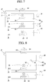
FIG. 5 is a view illustrating a first example of a refrigeration cycle of a refrigerator according to an embodiment of the present disclosure,FIG. 6 is a view illustrating a second example of a refrigeration cycle of a refrigerator according to an embodiment of the present disclosure,FIG. 7 is a view illustrating a third example of a refrigeration cycle of a refrigerator according to an embodiment of the present disclosure, andFIG. 8 is a diagram illustrating a fourth example of a refrigeration cycle of a refrigerator according to an embodiment of the present disclosure. - The refrigeration cycles illustrated in
FIGs. 5 to 8 may be applied to a refrigerator having three spaces (hereinafter, referred to as first, second, and third spaces) that may have different storage temperature ranges from each other. For example, the refrigeration cycles may be applied to at least one of i) a refrigerator having a first space W1, a separate second space W2, and a separate third space W3, ii) a refrigerator having a first storage chamber W having the first space W1 and the second space W2, and a second storage chamber C partitioned from the first storage chamber W, or iii) a refrigerator having a first storage chamber W and second and third storage chambers partitioned from the first storage chamber W. - The refrigeration cycle illustrated in
FIGs. 5 to 7 may include acompressor 100, acondenser 110, a plurality of expansion mechanisms (or valves) 130', 130, 140, and a plurality ofevaporators - The plurality of
evaporators first evaporators 150', 150 capable of independently cooling the first space W1 and the second space W2, respectively, and asecond evaporator 160 that can cool a second storage chamber C. One of the pair offirst evaporators 150' and 150 may be an evaporator 150' cooling the first space W1, and the other of the pair offirst evaporators 150' and 150 may be anevaporator 150 cooling the second space W2. - The plurality of
expansion mechanisms first expansion mechanisms 130' and 130 connected to a pair offirst evaporators 150' and 150, and asecond expansion mechanism 140 connected to asecond evaporator 160. Any one of the pair offirst expansion mechanisms 130' and 130 may be an expansion mechanism 130' connected to any one 150' of the pair offirst evaporators 150' and 150, and the other of the pair offirst expansion mechanisms 130' and 130 may be anexpansion mechanism 130 connected to theother one 150 of the pair offirst evaporators 150' and 150. - The flow path switching mechanism 120' may include a
first valve 121 capable of controlling a refrigerant flowing into the pair offirst expansion mechanisms 130' and 130, and asecond valve 122 capable of controlling a refrigerant flowing into thefirst valve 121 and thesecond expansion mechanism 140. - The refrigerator having the refrigeration cycle illustrated in
FIGs. 5 to 7 may include a pair offirst fans 181' and 181, and asecond fan 182 for circulating cold air in the space of the second storage chamber C to the space of thesecond evaporator 160 and the second storage chamber C and may further include acondensation fan 114 for blowing outside air to thecondenser 110. Any one 181' of the pair offirst fans 181' and 181 may be a fan for the first space in which cold air in the first space W1 can be circulated into any one 150' of the pair offirst evaporators 150' and 150 and the first space W1. In addition, theother one 181 of the pair offans 181' and 181 may be a fan the second space in which cold air in the second space W2 can be circulated into any one 150 of the pair offirst evaporators 150' and 150 and the second space W2. - The refrigeration cycle illustrated in
FIG. 5 may include a first parallel flow path in which a pair offirst evaporators 150' and 150 are connected in parallel and a second parallel flow path in which a pair offirst evaporators 150' and 150 are connected to thesecond evaporator 160 in parallel. In this case, a one-way valve 168 may be installed at an outlet side of thesecond evaporator 160 to prevent the refrigerant at the outlet side of thesecond evaporator 160 from flowing back to thesecond evaporator 160. - The refrigeration cycle illustrated in
FIG. 6 may include a parallel flow path in which a pair offirst evaporators 150' and 150 are connected in parallel and aserial flow path 123 in which the pair offirst evaporators 150' and 150 are connected to asecond evaporator 160 in series. One end of theserial flow path 123 may be connected to a parallel flow path in which a pair offirst evaporators 150' and 150 are connected in parallel. The other end of theserial flow path 123 may be connected between thesecond expansion mechanism 140 and the inlet of thesecond evaporator 160. In this case, a one-way valve 168 may be installed at the outlet side of thesecond evaporator 150 to prevent the refrigerant at the outlet side of thesecond evaporator 160 from flowing back to thesecond evaporator 160. - The refrigeration cycle illustrated in
FIG. 7 may include aserial flow path 125 in which a pair offirst evaporators 150' and 150 are connected in series, and, a parallel flow path in which the pair offirst evaporators 150' and 150 are connected to thesecond evaporator 160 in parallel. One end of theserial flow path 125 may be connected to the outlet side of any one 150 of the pair offirst evaporators 150' and 150. The other end of theserial flow path 125 may be connected to an inlet side of the other 150' of the pair of first evaporators 150' and 150'. In this case, a one-way valve 168 may be installed at the outlet side of thesecond evaporator 160 to prevent the refrigerant at the outlet side of thesecond evaporator 160 from flowing back to thesecond evaporator 160. - The refrigeration cycle illustrated in
FIG. 8 may include onefirst evaporator 150 instead of the pair offirst evaporators 150' and 150 illustrated inFIGs. 5 to 7 , and onefirst expansion mechanism 130 instead of the pair ofexpansion mechanism 130' and 130. In addition, the refrigeration cycle illustrated inFIG. 8 may include a flow path switching mechanism (or valve) 120 for controlling the refrigerant flowing into thefirst expansion mechanism 130 and thesecond expansion mechanism 140, and the flowpath switching mechanism 120 may include a refrigerant valve that can be switched so that the refrigerant flowing from thecondenser 110 flows to thefirst expansion mechanism 130 or thesecond expansion mechanism 140. In addition, a one-way valve 168 may be installed at the outlet side of thesecond evaporator 160 to prevent the refrigerant at the outlet side of thesecond evaporator 160 from flowing back to thesecond evaporator 160. - Since other configurations and actions other than one
first evaporator 150, onefirst expansion mechanism 130, a flowpath switching mechanism 120, and a one-way valve 168 of the refrigeration cycle illustrated inFIG. 8 are the same as or similar to those of the refrigeration cycle illustrated inFIGs. 5 to 7 , a detailed description with respect to those will be omitted. - In addition, the refrigerator having a refrigeration cycle illustrated in
FIG. 8 may include afirst fan 181 circulating cold air of the first storage chamber W into thefirst evaporator 150 and the first storage chamber W instead of the pair offirst fans 181' and 181 illustrated inFIGs. 5 to 7 . In addition, the refrigerator having the refrigeration cycle illustrated inFIG. 8 may include afirst damper 191 for controlling cold air flowing into the first space W1 after being cooled by thefirst evaporator 150 and asecond damper 192 for controlling the cold air flowing into the second space W2 after being cooled by thefirst evaporator 150. Only one of thefirst damper 191 and thesecond damper 192 may be provided. Meanwhile, in the refrigerator, one damper may selectively supply air cooled by theevaporator 150 to at least one of the first space W1 and the second space W2. - Modification of the examples of the refrigeration cycle illustrated in
FIGs. 5 to 8 may be applied to a refrigerator having two spaces having different storage temperature ranges from each other. In other words, the modification examples of the refrigeration cycle may be applied to a refrigerator having a first space W1 and a second space W2 or a refrigerator having a first storage chamber W and a second storage chamber C. In certain examples, the refrigeration cycle can be configured with a cycle which does not include the flowpath switching mechanisms second expansion mechanism 140, thesecond evaporator 160, thesecond fan 182, and the one-way valve 168. -
Fig. 9 is a control block diagram illustrating a refrigerator according to an embodiment of the present disclosure. The refrigerator may include acontroller 30 that controls various electronic devices such as a motor provided in the refrigerator. Thecontroller 30 may control the refrigerator according to an input value of the input device, such as a user command, or an input value that is generated by the refrigerator, such as an input value generated based on sensor reading related to stored objects, ambient conditions, a location of the refrigerator, a sensed attribute of the user, etc. - The input device may include at least one of a
communication device 31 which receives a signal from an external device such as a remote controller such as a remote controller or a mobile terminal such as a mobile phone, amicrophone 32 that changes a user's voice to a sound signal, asensing unit 33 which can sense a user's motion, a proximity sensor 34 (or a distance sensor) which can sense the user's proximity, a touch sensor 35 which can sense the user's touch, adoor switch 36 which can detect the opening and closing of the door, and atimer 37 which can measure the lapse of time, and acontrol panel 39 capable of inputting a target temperature. - As previously described, the refrigerator may include a see-through door. The see-through door may be a door that can selectively switched between a first state in which the door is at least partially transparent and a user can see through the door (a see-through activation state), and a second state in which the door is at least partially opaque and a user cannot see through the door (a see-through deactivation state). The see-through door may be a door that is changed from a see-through deactivation state to a see-through activation state or is changed from a see-through activation state to a see-through deactivation state according to an input value provided to the
controller 30 through the input device. In another example, the see-through door may be a door in which the see-through door is changed from see-through deactivation state to see-through activation state when the see-through door is closed and according to an input value provided to thecontroller 30 through the input device. - An example of an operation method according to the input device is now described. The
sensing unit 33 may include a vibration sensor. For example, the vibration sensor may be disposed on the rear surface of the front panel, and the vibration sensor may be formed in black such that visible exposure of the vibration sensor may be minimized. For example, thesensing unit 33 may include a microphone or other audio sensor disposed, for example, on the rear surface of the front panel, and the microphone may sense sound waves of vibration applied to the front panel. When a user provides a particular input, such as tapping the panel assembly 23 a plurality of times at a predetermined time interval, the specific input may be detected through thesensing unit 33, and thecontroller 30 may change the see-through door to be activated or deactivated based on the detected input. Additionally or alternatively, thesensing unit 33 may be a device for imaging a user's motion, such as a camera. It may be determined whether the image photographed by thesensing unit 33 is similar or identical to a specific motion input in advance, and may be changed to activate or deactivate the see-through door according to the determination result. - Similarly, if it is determined that the user or a part of the user (e.g., the user's hand) is positioned within a predetermined distance or less (e.g., 30 cm or less) of a portion of the refrigerator according to the value detected by the
proximity sensor 34, the see-through door may be changed between the activated or deactivated states. In another example, the see-through door may be changed between the activated or deactivated states when it is determined that the user positioned with a predetermined distance or less and is moving toward the refrigerator according to the value detected by theproximity sensor 34. - In another example, when the
controller 30 determines that the door is closed according to the value detected by thedoor switch 36, the see-through door may be activated, and when it is determined that the door is open, the see-through door may be changed to be inactivated. For example, the see-through door may be in the deactivated state when opened and may remain in the deactivated state when closed, until a particular input is received that prompts the see-through door to be switched to the activated state. - The see-through door may be controlled to be deactivated after a certain time elapses after being activated according to the value input through the
timer 37. For example, the see-through door may be controlled to be deactivated after a certain time elapses after an input to activate the see-through door is received. In another example, according to the value input through thetimer 37, the see-through door may be controlled to be activated when a predetermined time elapses after being deactivated. - If the mechanisms for activating or deactivating the see-through door (e.g., a transparency control module) may include, for example, the
panel assembly 23 and thelight source 38. As an example in which the see-through door is activated or deactivated, there may be a case where the transparency of the see-through door itself may vary. For example, the see-through door may maintain in an opaque state when no current is applied to thepanel assembly 23 and may be changed to be transparent when current is applied to thepanel assembly 23. In another example, it can be a case that, when thelight source 38 installed inside the see-through door is turned on, the user may see the storage chamber through the see-through door by the light emitted from thelight source 38. Thelight source 38 may make thepanel assembly 23 appear transparent or translucent so that an inside of the refrigerator (a side of the storage chamber relative to the panel assembly) looks brighter than outside of the refrigerator (outside relative to the panel assembly). Thelight source 38 may be mounted on the light source mounting portion formed on thecabinet 1 or the light source mounting portion formed on the door and may be disposed to emit light toward thepanel assembly 23. - The
controller 30 may control thedoor opening module 11 according to the input value of the input device. Thecontroller 30 may control thelifting module 13 according to the input value of the input device. -
FIG. 10 is a perspective view illustrating a see-through door of a refrigerator according to an embodiment of the present disclosure. The refrigerator may include a door (hereinafter, a see-through door) through which a user may view the storage chamber through a see-through window without opening thedoor 50 from the outside of the refrigerator. The see-through door may include anouter door 22 and apanel assembly 23. - The
outer door 22 may be opaque, and anopening portion 21 may be formed in (e.g., in a central region) of theouter door 22. Theouter door 22 may form an outer appearance of the see-through door. Theouter door 22 may be rotatably connected to or connected to thecabinet 1 to be capable of being advanced and retracted to open storage chamber W. Thepanel assembly 23 may be disposed in the openingportion 21. Thepanel assembly 23 may be disposed to shield the openingportion 21. Thepanel assembly 23 can form the same outer appearance as the front surface of theouter door 22. - The see-through door may be provided to open and close the storage chamber which mainly stores goods (for example, wine) having a large quality change according to the temperature change (e.g., the goods are preferable stored in a narrow temperature range to preserve a quality of the goods). In a case where goods having a large quality change due to temperature change are mainly stored in the storage chamber W, the storage chamber W is preferably opened and closed as short as possible, the number of opening and closing is preferably minimized, and the see-through door is preferably installed to open and close the storage chamber W so that a user may view goods within the storage chamber without opening the door and disturbing the temperature within the storage chamber. For example, the see-through door may be provided in the door for opening and closing at least one of a specific goods storage chamber, a constant temperature chamber, or a priority storage chamber.
-
FIG. 11 is a plan view when an example of a swinging-type door according to an embodiment of the present disclosure is opened in a door opening module. In the refrigerator, a door opening and closing the storage chamber may be an automatic door, and the door for opening and closing the specific goods storage chamber, the constant temperature chamber, and a priority storage chamber may be an automatic door. The refrigerator may include adoor opening module 11 that provides a force for automatically opening thedoor 5. For example, the automatic door may be controlled to be opened or closed according to an input value provided to thecontroller 30 through the input device. For this purpose, thecontroller 30 may control thedoor opening module 11. - The
cabinet 1 may be coupled to ahinge mechanism 40 in which thehinge shaft 42 is connected to thedoor 5. The refrigerator may further include amodule cover 70 that may cover thehinge mechanism 40 and thedoor opening module 11 together. In addition, thedoor opening module 11 may include adrive motor 72, apower transmission unit 74, and apush member 76. - When the power of the refrigerator is turned on, the
controller 30 may wait to receive an open command of thedoor 5. When the door opening command is input through the input device, thecontroller 30 may transmit an opening signal to thedrive motor 72 included in thedoor opening module 11. - When the
controller 30 transmits an opening signal to thedrive motor 72, thedrive motor 72 may be rotated in a first direction to move thepush member 76 from the initial position to the door opening position. When thedrive motor 72 rotates in the first direction, thepower transmission unit 74 may transmit a first direction rotational force of thedrive motor 72 to thepush member 76, and thepush member 76 may push the door while protruding forward, and thedoor 5 may be rotated in the forward direction with respect to thecabinet 1. - The
controller 30 may determine whether thepush member 76 has reached the door opening position in a process of rotating in the first direction of thedrive motor 72. For example, the controller may determine that thepush member 76 has reached the door opening position when the cumulative rotational speed of thedrive motor 72 reaches the reference rotational speed. Thecontroller 30 may stop the rotation of thedrive motor 72 when it is determined that thepush member 76 has moved to the door opening position. - In a state where the
door 5 is rotated by a predetermined angle, the user can manually increase the opening angle of thedoor 5. When the user increases the opening angle of the door in a state where thepush member 76 moves thedoor 5 to the door opening position, the door sensor including amagnet 46 and areed switch 48 can sense the manual opening of thedoor 5, and if the manual opening of thedoor 5 is sensed by the door sensor, thecontroller 300 can output a return signal to thedrive motor 72. - The
controller 30 may transmit the return signal to thedrive motor 72 so that thepush member 76 returns to the initial position and thedrive motor 72 may be reversely rotated in a second direction opposite to the first direction. If it is determined that thepush member 76 has returned to the initial position, thecontroller 30 may stop thedrive motor 72. -
FIG. 12 is a sectional view when another example of a door according to an embodiment of the present disclosure is opened by a door opening module 11'. In the example shown inFIG. 12 , the door is drawer that may be automatically opened by the door opening module 11' that applies an outward force. - The door opening module 11' illustrated in
FIG. 12 may automatically open the door (or drawer) 6 disposed in thecabinet 1 to be capable of being advanced and retracted. The refrigerator may include a first door provided at a relatively higher at a greater height and a second door that is relatively lower and having a smaller height, and the door opening module 11' may be installed to automatically open a door having a lower height than other doors. Such a door may be a retractable automatic door which is automatically opened by the door opening module 11'. Thedoor 6 advanced and retracted by the door opening module 11' may include a drawer body (or bin) 6A and a door body (or drawer front) 6B disposed at thedrawer body 6A to open and close the storage chamber. - The door opening module 11' may include a
drive motor 80, apinion 82, and arack 84. Thepinion 82 may be connected to the rotation shaft of thedrive motor 80. Therack 84 may extend from thedoor 6, in particular, thedrawer body 6A. The refrigerator may further include a door sensor that senses a position of thedoor 6, and the door sensor may sense a pair of magnets 46' spaced apart from thedoor 6 and a reed switch (or Hall sensor) 48' sensing the magnet 46'. - When the power of the refrigerator is turned on, the
controller 30 may wait to receive an opening command of thedoor 6. When the door opening command is input through the input device, thecontroller 30 may transmit an opening signal to thedrive motor 80. - The
drive motor 80 may be activated to rotate in the first direction by thecontroller 30 when an opening signal is input, and thepinion 82 and therack 84 may transmit the rotational force of thedrive motor 80 to thedrawer body 82. Thedrawer body 6A may advance thedoor body 6B while advancing forward in the storage chamber, and thedoor body 6B can be advanced to be spaced apart from thecabinet 1 toward the front of thecabinet 1. Thecontroller 30 may sense that thedoor 6 has reached the opening position by the door sensor, and when thedoor 6 has reached the opening position, thecontroller 30 may stop the rotation of thedrive motor 80. - When the
drawer body 6A is advanced as described above, the upper surface of thedrawer body 6A may be exposed. In a state where thedrawer body 6A is advanced to the opening position, the user can enter a door closing command such that thedrawer body 6A retracts to the closing position via the input device. For example, if the motion sensed by thesensing unit 33 coincides with a specific motion, thecontroller 30 may transmit a close signal to thedrive motor 80. In another example, thecontroller 30 may sense the proximity of the user by theproximity sensor 34 and transmit a closing signal to thedrive motor 80 when theproximity sensor 34 detects that the user has moved more than a predetermined distance (e.g., toward the proximity sensor 34). - When the close signal is input, the
drive motor 80 may be reversely rotated in a second direction opposite to the first direction. In reverse rotation of thedrive motor 80, thepinion 82 and therack 84 can transmit the rotational force of thedrive motor 80 to thedrawer body 6A, and while thedrawer body 6A retracts into the storage chamber, thedoor body 6B can be retracted and thedoor body 6B can be retracted in close contact with thecabinet 1 toward the front of thecabinet 1. Thecontroller 30 may sense that thedoor 6 has reached the closing position by the door sensor, and if thedoor 6 has reached the closing position, thecontroller 30 may stop the reverse rotation of thedrive motor 80. -
FIG. 13 is a sectional view illustrating when theholder 12 lifts while the door is opened according to the embodiment of the present disclosure. As previously described, the refrigerator may further include a lifting module (also referred to as a lift or elevator) 13 which allows theholder 12 to be automatically lifted and lowered after theholder 12 is moved forward in a state where thedoor 50 is opened. Theholder 12 may be a shelf, a drawer, a basket, or the like on which goods can be placed. Thelifting module 13 may be disposed in the storage chamber or at least one of therotatable door 5 and the advancing and retractingtype door 6 for opening and closing the storage chamber. The refrigerator may have both a first holder provided higher at a greater height and a second holder provided lower at a smaller lower height. - The
lifting module 13 may be disposed in a low storage chamber associated with aholder 12 having a lower height thanother holders 12. In another example, thelifting module 13 may function for lowering a holder and may be arranged in a storage chamber in which a holder having a relatively greater height than other holders is located. - An example of the
lifting module 13 will be described. An example of thelifting module 13 may include alower frame 93, anupper frame 94, a lifting and loweringmechanism 92 having at least onelink 95, and adrive mechanism 90 capable of lifting and lowering theupper frame 94. Thedrive mechanism 90 may include a lifting and loweringmotor 91 and a power transmission member connected to the lifting and loweringmotor 91 to transfer the drive force of the lifting and loweringmotor 91 to theupper frame 94. - When the refrigerator is turned on, the
controller 30 may wait for a lifting command of theholder 12 to be input. When the lifting command is input through the input device, thecontroller 30 may transmit a lifting signal to the lifting and loweringmotor 91 included in thelifting module 13. In another example, thecontroller 30 may automatically generate the lifting command when a drawer is fully opened and other, higher drawers are closed. When thecontroller 30 transmits an opening signal to the lifting and loweringmotor 91, the lifting and loweringmotor 91 may rotate in a first direction and theupper frame 94 may lift theholder 12 to the upper side of thedrawer body 6B. - The user may input a lowering command through the input device, and the
controller 30 may transmit a lowering signal to the lifting and loweringmotor 91 when the lowering command is input through the input device. In another example, thecontroller 30 may automatically generate the lowering command when a lifted drawer is being closed or other, higher drawers start to be closed. For example, the lifting and loweringmotor 91 may be reversely rotated in a second direction opposite to the first direction. Upon reverse rotation of the lifting and elevatingmotor 91, theupper frame 94 may be lowered to the inner lower portion of thedrawer body 82, and theholder 12 may be inserted into thedrawer body 6B together with theupper frame 94. In another example, the lifting and loweringmotor 91 may be rotating in a same direction when lowering or lifting theholder 12, and a vertical movement direction may be adjusted by a power transmission member, such as to adjust a quantity and/or position of gears to receive a rotational force of the lifting and loweringmotor 91. -
Fig. 14 is a front view illustrating a storage chamber of a refrigerator according to an embodiment of the present disclosure, andFig. 15 is a rear view illustrating an inside of theinner guide 200 according to an embodiment of the present disclosure. Theinner guide 200 may be disposed in thecabinet 1 in which the first storage chamber W is formed, and may be disposed in theinner case 8 to partition the storage space and the air flow path P. The air flow path P may be formed between theinner guide 200 and theinner case 8 of the inner space of theinner case 8 or may be formed in theinner guide 200. - One example of the temperature adjusting device disposed in the air flow path P may be cooling device(s) capable of cooling the air passing through the air flow path P, and may cool the storage chamber. The cooling device(s) may be a heat absorbing body of the thermoelectric element, an
evaporator 150 through which the refrigerant passes, or the like. - Hereinafter, the temperature adjusting device disposed in the refrigerant flow path P will be described as an example of cooling device(s), but the temperature adjusting device disposed in the air flow path P is not limited to being a cooling device(s), but may be a heating device such as a heater. For convenience, it will be described with reference to the
same reference numeral 150 as the evaporator which can be an example for the temperature adjusting device disposed in the air flow path P. - At least one
fan inner case 8 or theinner guide 200. Thefan 181 may be disposed in theinner guide 200 to circulate air in the storage space to the air flow path P and the storage space. Thecirculation fan 186 may circulate air in the storage space and may be an HG fan. Thecirculation fan 186 may be disposed in the circulation flow path P4, and the air of the storage space can flow into the circulation flow path P4 other than the air flow path P, and blow the air of the circulation flow path P4 into the storage space. The circulation flow path P4 may be formed to be partitioned from the air flow path P in theinner guide 200 and may be formed to communicate with the first space W1. - The
inner guide 200 may form a storage space together with theinner case 8. Theinner guide 200 may cover thetemperature adjusting device 150 and thefan 181. When theinner guide 200 is disposed in front of the rear body of theinner case 8, the storage space may be a space in front of theinner guide 200 among the interior of theinner case 8, and the air flow path P may be formed between theinner guide 200 and the rear body of theinner case 8 or may be formed inside theinner guide 200. - When the refrigerator further includes a
partition member 3, thepartition member 3 may be closer to a lower end of the storage chamber. - The
inner guide 200 may have adischarge port 204 and asuction port 205 spaced apart from each other, and thedischarge port 204 and thesuction port 205 may be formed to face the first space W1. Theinner guide 200 may have a heat exchange flow path P1 in which the first cooling device(s) 150 and thefan 181 are received. Theinner guide 200 may have a discharge flow path P2 through which air blown by thefan 181 is guided to thedischarge port 204. Theinner guide 200 may be provided with an additional discharge flow path P3 for guiding the air blown by thefan 181 to be discharged to theadditional discharge port 321. - The heat exchange flow path P1, the discharge flow path P2, and the additional discharge flow path P3 may constitute an air flow path P for guiding air to circulate through the
temperature adjusting device 150 and the storage space, and thetemperature adjusting device 150 and thefan 181 may adjust the temperature of the first space W1 and the second space W2 in a state of being accommodated in the air flow path P. - The
air guide 400 may include afront housing 410 and a rear housing 420 in which thefan 181 is received. Theair guide 400 may have anoutlet 412 communicating with theadditional discharge port 321. Theoutlet 412 may be formed to face theadditional discharge port 321 to discharge air to theadditional discharge port 321 or may be in communication with theadditional discharge port 321 through a discharge duct. - The refrigerator may include a
guide 234 for guiding air forced by thefan 181 inside theair guide 400 to theoutlet 412. Theguide 234 may be formed in thedischarge guide 202 to guide the air blown from thefan 181 to theoutlet 412. Theair guide 400 may be provided with ascroll 413 and anopening portion 414 for guiding air to the discharge flow path P2. Thescroll 413 may guide the air blown from thefan 181 to theopening portion 414. Theopening portion 414 may communicate with the lower end of the discharge flow path P2. - The
first damper 191 may be disposed in the air flow path P and may adjust the air supplied to the first space W1. Thesecond damper 192 may be disposed in the air flow path P and may adjust the air supplied to the second space W2. - The
circulation fan 186 may be disposed in theinner guide 200. In theinner guide 200, when thecirculation fan 186 is operated, a circulation flow path P4 through which air passes may be formed. Theinner guide 200 may be formed with aninlet 188 through which air in the storage space flows into the circulation flow path P4 when thecirculation fan 186 is driven. Theinner guide 200 may have anoutlet 189 through which air from the circulation flow path P4 is discharged into the storage space. - The
inlet 188 and theoutlet 189 may communicate with the first space W1. Thecirculation fan 186 may circulate air in the first space W1 into the circulation flow path P4 and the first space W1. Apurifying unit 185 such as an air purifying filter may be disposed in the circulation flow path P4, and the air passing through the circulation flow path P4 may be purified by thepurification unit 185. Theinner guide 200 may further include aninlet body 187 forming thedischarge guide 202 and theinlet 188. - The
inner guide 200 may be provided with afirst temperature sensor 190 for sensing the temperature of the first space W1 and asecond temperature sensor 390 for sensing the temperature of the second space W2. - The
inner guide 200 may include adischarge guide 202 and aninner cover 300. Thedischarge guide 202 may be disposed higher than theinner cover 300. Thedischarge guide 202 may include adischarge body 210 in which thedischarge port 204 and thesuction port 205 are formed, and aflow path body 230 disposed in thedischarge body 210 and forming the discharge flow path P2. - The
temperature adjusting device 150 and thefan 181 can supply air to the first space W1 and the second space W2 through the air flow path P formed by at least one of thedischarge guide 202 and theinner cover 300. Thetemperature adjusting device 150 may be received in theinner cover 300. - The
discharge guide 202 and theinner cover 300 are configured to be received inside theinner case 8 together with thetemperature adjusting device 150 and thefan 181, and the volume occupied by thedischarge guide 202, theinner cover 300, thetemperature adjusting device 150, and thefan 181 may be minimized. Thefan 181 is to forcedly flow the air heat exchanged with thetemperature adjusting device 150, and the air flowing by thefan 181 can be discharged and guided to the first space W1 and the second space W2 by thedischarge guide 202 and theinner cover 300. - The
discharge guide 202 may face the first space W1, and thedischarge hole 204 and thesuction hole 205 may be formed in thedischarge guide 202. Theinner cover 300 may be connected to thedischarge guide 202. Theinner cover 300 may face the second space W2, and theadditional discharge port 321 and theadditional suction port 341 may be formed in theinner cover 300. - A portion of the
discharge guide 202 facing the first space W1 may be provided with a heating air generation module (HG)module 184 and afirst temperature sensor 190. TheHG module 184 may include acirculation fan 186. TheHG module 184 may include apurifying unit 185 such as an air purifying filter and purify the air in the first space W1. - The height of the
additional discharge port 321 may be higher than the height of theadditional suction port 341. Theadditional discharge ports 321 may be formed on theinner cover 300, and the air blown by thefan 181 may be discharged into the second space W2 through theadditional discharge ports 321. Theadditional suction port 341 may be formed at the lower portion of theinner cover 300, and the air suctioned into theadditional suction port 341 may flow to thetemperature adjusting device 150. Thesecond temperature sensor 390 may be disposed in theinner cover 300 to sense the temperature of the second space W2. - As previously described, the refrigerator may include at least one heating device for heating the storage space, and the refrigerator may perform a heating operation H (see
Fig. 4 ) using the heating device. At least one heating device may be operated independently from the temperature adjusting device (or refrigeration system) 150 disposed in the air flow path P. - The refrigerator may perform the cooling operation E (see
Fig. 4 ) by thetemperature adjusting device 150 disposed in the air flow path P and may perform the heating operation H by the at least one heating device. The heating device may be disposed to heat only one of the first space W1 and the second space W2 and may be provided for each of the first space W1 and the second space W2. The heating device is preferably installed at a position thermally separated from the temperature adjusting device disposed in the air flow path P. - The heating device may include a
first heating device 171 for heating the first space W1. Thefirst heating device 171 may include a pair of firstside heating devices 173 and 174 disposed in thefirst body 8C facing the first space W1. Thefirst heating device 171 may include aninner heating device 175 disposed on thepartition member 3 or theshelf 2. Theinner heating device 175 is disposed to be exposed to thepartition member 3, theshelf 3, or the outer surface of the heating body to directly heat the air in the storage space. - The heating device may further comprise a
second heating device 172 for heating the second space W2. Asecond heating device 172 may include a pair of secondside heating devices second body 8D towards the second space. Asecond heating device 172 may further include alower heating device 178 disposed in the lower body of theinner case 8. - The
controller 30 may control thefan 181 and the heating device. Thecontroller 30 may drive or stop thefan 181. Driving thefan 181 may mean that thefan 181 is on, and stopping of thefan 181 may mean that thefan 181 is off. - The
controller 30 may operate or stop the heating device. When the heating device is a heater, the operation of the heating device may mean that the temperature of the heater is increased, and for example, it may be the case that the heater is on. Stopping the heating device may mean that the temperature of the heater is not increased, and for example, it may be the case that the heater is off. - The
controller 30 may operate or stop thetemperature adjusting device 150. When thetemperature adjusting device 150 is an evaporator, the operation of thetemperature adjusting device 150 may mean that the refrigerant flows to thetemperature adjusting device 150, and for example, may be a case where thecompressor 100 is on and the refrigerant valve is in the evaporator mode which supplies refrigerant to the evaporator. The stop of thetemperature adjusting device 150 may mean that the refrigerant does not flow to thetemperature adjusting device 150, and for example, a mode in which the refrigerant valve does not supply the refrigerant to the evaporator (for example, a mode for supplying a refrigerant to a second evaporator, or the like). - During the cooling operation of the first space W1, the cooling device(s) and the
fan 181 may be operated, and thefirst heating device 171 may be stopped. In this case, the cooling device(s) may control the flowpath switching mechanism 120, 120', thecompressor 100, or the like so that the refrigerant is supplied to thetemperature adjusting device 150, and thefirst damper 191 may be opened. - During the heating operation of the first space W1, the
first heating device 171 may be operated. In this case, at least one of thefan 181 and thecirculation fan 186 may be operated. During the heating operation of the first space W1, thecirculation fan 186 may be driven so that the air in the first space W1 circulates through thefirst heating device 171 and the circulation flow path P4, and thus the first space W1 may be heated by convection. In this case, the cooling device(s) may be controlled so that the air of the air flow path P is not discharged into the first space W1, and, to this end, thefirst damper 191 may be closed or thefan 181 may be stopped. - In the heating operation of the first space W1, the
fan 181 may be operated so that the air in the first space W1 circulates through thefirst heating device 171 and the air flow path P, so that the first space W1 may be heated by convection. In this case, the cooling device(s) may control the flowpath switching mechanisms 120 and 120', thecompressor 100, and the like such that the refrigerant is not supplied to thetemperature adjusting device 150. - In the cooling operation of the second space W2, the cooling device(s) and the
fan 181 may be operated, and thesecond heating device 172 may be stopped. In this case, the cooling device(s) may control the flowpath switching mechanism 120, 120', thecompressor 100, and the like, such that the refrigerant is supplied to thetemperature adjusting device 150, and thesecond damper 192 may be opened. - In the heating operation of the second space W2, the
second heating device 172 may be operated. In this case, thefan 181 may be operated or stopped. In the heating operation of the second space W2, thefan 181 is operated so that the air in the second space W2 circulates through thesecond heating device 172 and the air flow path P, and thus the second space W2 may be heated by convection. In this case, the cooling device(s) may control the flowpath switching mechanism 120, 120' and thecompressor 100 such that the refrigerant is not supplied to thetemperature adjusting device 150. Additionally, in the heating operation of the second space W2, thefan 181 may be stopped, and in this case, thesecond heating device 172 may heat the second space W2 by conduction. -
Fig. 16 is a view illustrating a change in the storage chamber temperature and storage chamber humidity in the cooling mode of the storage chamber according to an embodiment of the present disclosure. Curve J ofFig. 16 is a temperature of storage space, and curve K ofFig. 16 is a relative humidity of storage space. - Region L in
Fig. 16 corresponds to a process in which thetemperature adjusting device 150 and thefan 181 are operated, and the air in the storage space may circulate through the storage space and thetemperature adjusting device 150, and the temperature and relative humidity of the storage space can be gradually lowered, respectively. - Region M in
Fig. 16 may correspond to a process in which some of the moisture in thetemperature adjusting device 150 is moved to the storage space while thetemperature adjusting device 150 is naturally defrosted by the air flowed from the storage space while thetemperature adjusting device 150 is stopped and thefan 181 is driven such that temperature and relative humidity of the storage space may be increased together. - Region N in
Fig. 16 may correspond to a process in which the temperature of the storage space is increased while thetemperature adjusting device 150 is stopped and thefan 181 is driven, and the relative humidity of the storage space may be lowered again by the temperature rise of the storage space. - The relative humidity of the storage space can be increased or decreased by various factors, as illustrated in
Fig. 16 . These factors may include, for example, be the size of thetemperature adjusting device 150, the time for which thefan 181 is operated while thetemperature adjusting device 150 is stopped, the flow rate of the fan, and the temperature of the storage space. - As the humidity inside the storage chamber changes, the quality of goods stored in the storage chamber may be reduced. For example, when the humidity inside the storage chamber is low, the cork of the wine bottle stored in the storage chamber dries up, and oxygen may flow into the wine bottle, potentially causing the wine to oxidize, mold to form around the cork, and the quality of the wine to be drastically degraded. For this reason, in certain countries, the specification of the relative humidity range within a storage chamber may be specified for the storage chamber which stores particular goods.
- Providing a separate humidifier for adjusting the humidity inside the storage chamber may cause the structure of the refrigerator to be more complicated and to include costs. As another example, an opening may be installed to allow air flow between the inside of the storage chamber and the outside of the storage chamber, but this opening would not allow the humidity in the storage chamber to be actively controlled. Meanwhile, since the ice is gradually formed into the cooling device(s) and its surroundings when the cooling device(s) starts the cooling operation, a separate defrost heater may be provided at a position adjacent to the cooling device(s) in order to remove ice formed on the cooling device(s), but, in this case, since heating device(s) operates near the cooling device(s), there is a disadvantage in terms of power consumption, and there is a problem that the quality of the stored goods may be degraded because the storage chamber is not cooled during defrosting.
- In certain examples described herein, if a predetermined operation start condition is satisfied while the operation of the cooling device(s) is ended, the fan for the cooling device(s) may be driven to supply moisture to the storage chamber. By supplying moisture provided by the cooling device(s) and the ice formed around the storage chamber, the humidity inside the storage chamber can be maintained, and the amount of ice formed on the cooling device(s) and the surroundings can be gradually reduced. For this reason, a defrost heater can be can be minimized or avoided, and it is not necessary to provide a separate humidifier.
- The humidity care (or humidifying) mode of driving the fan for the cooling device(s) to supply moisture to the storage chamber may be started with at least one of the cooling mode or the heating mode is ended. The humidity care mode can start at least in standby mode. The humidity care mode may be started when at least one of the cooling device(s) and at least one of the heating device(s) are deactivated.
- In order to reduce the overcooling of the storage chamber, the air volume of the fan for the cooling device(s) during the humidity care mode driving may be controlled to be smaller than the air volume of the fan for the cooling device(s) during the cooling mode. Furthermore, when the refrigerator is partitioned into a first space W1 to which a first target temperature is set and a second space W2 to which a second target temperature lower than the first target temperature) is set, and when the humidity care operation for the first space W1 and the humidity care operation for the second space (W2) conflict, the performing of the humidity care operation for the first space can be prioritized since a storage space having a higher target temperature tends to have a larger deterioration in storage goods quality due to a decrease in storage chamber humidity.
- The number of rotations or on-time period (duty cycle) of the fan for the cooling device(s) during the humidity care mode driving may be controlled so that the relative humidity (RH) average of the storage chamber is over 50% RH. In another example, the fan speed or on-time period (duty cycle) for cooling device(s) during humidity care mode driving is controlled so that the relative humidity average of the storage chamber is 50% to 75% (European standard).
- The humidity care mode may be particularly performed to control the humidity of at least one of the expensive specific goods storage chambers, the constant temperature chamber, or the priority storage chamber of the refrigerator. The humidity care mode may be implemented to control the humidity of the storage chamber whose temperature is controlled by the cooling device(s) and the heating device(s).
- The refrigerator may perform a humidity care mode to control the humidity of the storage space. As previously described the humidity care mode may be a kind of humidification mode in which moisture of the cooling device(s), for example, moisture on the surface of the evaporator is moved to the storage space. In the humidity care mode, the fan can be driven to move the accumulated moisture from the cooling device.
- Thus, the humidity care mode may be defined as a mode in which the fan is driven and which supplies air to the storage space. For example, the humidity care mode may be a mode in which the air in the storage space W may flow into the cooling device(s) chamber by the fan and be humidified, and the humidified air in the cooling device(s) chamber may flow into the storage space to humidify the storage space, in a state where at least some of the cooling device(s) are in an off state (for example, the supply of refrigerant to the evaporator is interrupted, the thermoelectric element is off), and at least some of the heating device(s) are maintained in the off state (for example, the heater is turned off, the off of the thermoelectric element). For example, the humidity care mode may be a mode in which the air in the storage space flows to the evaporator by the fan to humidify, the humidified air flows into the storage space and humidifies the storage space, in a state where the refrigerant does not pass through the evaporator and the heater maintains the off state.
- In one example, the humidity care mode may be performed while the storage space is closed by the door, the cooling device(s) are stopped (e.g., no refrigerant flows to the evaporator for cooling the storage space), and the heating device(s) are stopped (for example, the heater is turned off). Accordingly, the humidity care mode may be started when a first condition in which the door to open and close the storage space is closed, and when both second condition in which the cooling device(s) is stopped and the third condition in which the heating device(s) is stopped are satisfied.
- For example, when the refrigerator repeats the cooling operation, the standby mode, and the cooling operation, the humidity care mode may be started when all of the first, second, and third conditions are satisfied in the non-cooling mode or the standby mode. Similarly, when the refrigerator repeats the heating operation, the standby mode and the heating operation, the humidity care mode may be started when all of the first, second, and third conditions are satisfied in the non-heating mode or the standby mode.
- When the refrigerator may be operated in the order of the cooling operation, the standby mode, and the heating operation, or in the order of the heating operation, the standby mode and the cooling operation, the humidity care mode may be performed, for example, in the non-cooling mode, the standby mode, or the non-heating mode.
- When the door to access the storage space is closed, and the
temperature adjusting device 150 is not operated, and the heating device is off, thecontroller 30 may perform a humidity care mode and drive thefan 181 in the humidity care mode. For example, thedoor switch 36 may transmit a signal to thecontroller 30 when the door is opened or closed, and thecontroller 30 may determine whether the door is closed according to the signal of thedoor switch 36. Thecontroller 30 may then operate or stop of thetemperature adjusting device 150 and turn on or off of the heating device according the storage chamber temperature sensed by the temperature sensor and the storage chamber target temperature, and start the humidity care mode when door is closed, thetemperature adjusting device 150 is stopped, and the heating device is turned off. - In certain examples, in the humidity care mode, the
controller 30 may control a damper that controls air flowing into the storage space, and controls the damper in an open mode for a set time (for example, 2 minutes or 4 minutes) and may drive thefan 181. - The
controller 30 may end the humidity care mode, for example, when the door is open, thetemperature adjusting device 150 is operated, and/or the heating device is turned on. In one example, thecontroller 30 may end the humidity care mode (e.g., to deactivate fan 181) when a desired level of humidity is achieved. When ending the humidity care mode, thecontroller 30 may continue to activatefan 181 but close a damper to the storage space such that defrosting of thetemperature adjusting device 150 continues without further providing humidity to the storage chamber. - When the door is opened, the outside air may flow into the storage space, and the humidity of the storage space may be increased by the inflow of the outside air. The
controller 30 may not implement the humidity care mode in order to minimize the power consumption and wear of thefan 181 since moisture is received from outside the storage (that is, due to the opening of the door). - The operation of the temperature adjusting device (or cooler) 150 may relate to controlling the cooling the storage space, and the operation of the heating device (or heater) may relate to controlling the heating the storage space. In the refrigerator, the humidity management of the storage space may be important for the previously described reasons, but in order to ensure constant temperature properties, the temperature management of the storage chamber may be more important, and the
controller 30 may perform the humidity care mode in a lower order of importance than controlling the cooling of the storage space (that is, the cooling operation) or the controlling the heating of the storage space (that is, heating operation). - The
controller 30 may resume the humidity care mode (e.g., resume activating the fan 181) when the door is closed, thetemperature adjusting device 150 is not operated, and the heating device is turned off after the humidity care mode is ended. For example, as previously described, the humidity care mode may stop when the door is opened, and thecontroller 30 may resume the humidity care mode (e.g., resume activating the fan 181) based on determining that the door is closed while thetemperature adjusting device 150 remain not operated, and the heating device remains turned off. - Meanwhile, the low temperature storage chamber partitioned from the storage space may be further formed in the
cabinet 1. Here, the low temperature storage chamber may include a space having a target temperature range lower than that of the storage space. For example, when the storage space is provided in the first storage chamber W, the low temperature storage chamber may be the second storage chamber C. - A low-temperature temperature adjusting device for cooling the low temperature storage chamber may be disposed in the low temperature storage chamber. When the
temperature adjusting device 150 is thefirst evaporator 150 for cooling the first storage chamber W, the low-temperature temperature adjusting device may be thesecond evaporator 160 for cooling the second storage chamber C, as shown inFIGs. 6-9 . In the following discussion, the low-temperature temperature adjusting device will be described with reference to thesecond evaporator 160 for the low-temperature temperature adjusting device. - In addition, the refrigerator may further include a low temperature fan for supplying air heat exchanged with the low-temperature
temperature adjusting device 160 to the low temperature storage chamber. In a case where thefan 181 is thefirst fan 181 disposed in the first storage chamber W, the low temperature fan may be thesecond fan 182 disposed in the second storage chamber C, as shown inFIGs. 6-9 . - Furthermore, a defrost heater for defrosting the low-temperature
temperature adjusting device 160 may be disposed in the low temperature storage chamber. Thecontroller 30 may separately perform a defrost mode for defrosting the low-temperature temperature adjusting device. - In some examples, the
controller 30 may wait or omit starting the humidity care mode while the refrigerator performs the defrost mode. For example, the refrigerator may further include a humidity sensor for sensing the humidity of the storage chamber W, and thecontroller 30 may perform the defrost mode (e.g., not operate the low-temperature temperature adjusting device 160) without starting the humidity care mode when the humidity of the storage space is equal to or greater than the set humidity. In addition, thecontroller 30 may end the humidity care mode when the humidity of the storage space is equal to or greater than the set humidity during the humidity care mode. - If the humidity of the storage space is equal to or greater than an appropriate level, such as during a time period after the opening of the door, the power consumption of the
fan 181 may be reduced by waiting to start the humidity care mode. Similarly, the power consumption of thefan 181 may be reduced by ending the humidity care mode if the humidity of the storage space is equal to or greater than the set humidity during the humidity care mode. - The refrigerator may perform a humidity care mode for each of the first space W1 and the second space W2. For example, the humidity care mode may include a first humidification mode in which the
fan 181 is driven, thefirst damper 191 is open, and thesecond damper 192 is closed (such that moist air is provided to the first space W1), and a second humidification mode in which thefan 181 is driven, thefirst damper 191 is closed, and thesecond damper 192 is open (such that moist air is provided to the second space W2). Thus, the first humidification mode may be a mode for supplying the moisture of thetemperature adjusting device 150 to the first space W1 without supplying the moisture to the second space W2, and the second humidification mode may be a mode for supplying the moisture of thetemperature adjusting device 150 to the second space W2 without supplying the moisture to the first space W1. - The
controller 30 may selectively perform one of the first humidification mode or the second humidification mode or may simultaneously perform both the first humidification mode and the second humidification mode (e.g., by opening both the first andsecond dampeners 191, 192). - The first humidification mode may be performed when the
first heating device 171 is off, and during a set time (for example, 2 minutes), thefan 181 may be driven, thefirst damper 191 may be opened, and thesecond damper 192 may be closed. The second humidification mode may be performed when thesecond heating device 172 is off, and during a set time (for example, 2 minutes), thefan 181 may be driven, and thesecond damper 192 may be opened, and thesecond damper 191 may be closed. As previously described, thecontroller 30 may alternate between the first humidification mode and the second humidification mode, such as to sequentially perform the second humidification mode and the first humidification mode. - The target temperature of the first space W1 may be higher than the target temperature of the second space W2, such that the temperature at the
temperature adjusting device 150 may be lower than the temperature of the second space W2, and the temperature of the second space W2 may be lower than the temperature of the first space W1. In the humidification care mode, the refrigerator may first perform the first humidification mode and then perform the second humidification mode. However, the humidification care mode may cause, when the temperature of the first space W1 is satisfied, low-temperature air from the at thetemperature adjusting device 150 to flow into the first space W1 such that the first space W1 may be supercooled (e.g., cooled to be below a desired temperature range). - Accordingly, when the conditions of initiating the humidification care mode are satisfied, the
controller 30 may perform the second humidification mode in preference to the first humidification mode. For example, in the situation where the condition of the humidification care mode is satisfied and thesecond heating device 172 is off, thecontroller 30 can drive thefan 181 during the setting time (for example, 2 minutes) to perform the second humidification mode by opening thesecond damper 192 while closingfirst damper 191. However, in the situation where the condition of the humidification care mode is satisfied while thesecond heating device 172 is turned on, thecontroller 30 may perform the first humidification mode or wait without performing the second humidification mode. - The humidification care mode may be performed in a situation where the humidity of the storage space is significantly lowered, and if a set (or delay) time (for example, 8 minutes) has not elapsed after the
fan 181 is turned off, the humidification care mode may be performed after the set time has elapsed. Thus, if the door is closed, no refrigerant flows to thetemperature adjusting device 150, a heating device is turned off, and the set time (for example, 8 minutes) has elapsed after thefan 181 is stopped, thecontroller 30 can perform the humidification care mode. The refrigerator may minimize the unnecessary humidification care mode and minimize the power consumption of thefan 181 by preventing the humidification care mode from being performed so frequently. -
Fig. 17 is a view illustrating a compressor operation and a fan operation when the first storage chamber is cooled and then the second storage chamber is cooled according to an embodiment of the present disclosure. For example, region (a) ofFig. 17 is a view illustrating a compressor operation when repeating the operation in which the second storage chamber C is cooled after the first storage chamber W is cooled, thecompressor 100 may be operated at a first capacity when the first storage chamber W is cooled and may be operated at a second capacity when the second storage chamber C is cooled and can maintain the off state after the second storage chamber C is cooled. Thecompressor 100 may be operated in the order of the operation of the first capability, the operation of the second capability, and the off state as time passes. - Region (b) of
Fig. 17 illustrates an example in which thefan 181 is turned on when the first storage chamber W is cooled, thefan 181 is turned off when the second storage chamber C is cooled, and thefan 181 is turned off when thecompressor 100 is turned off. - In contrast, region (c) of
Fig. 17 illustrates an example in which thefan 181 is turned on when the first storage chamber W is cooled, and thefan 181 is intermittently turned on when the second storage chamber C is cooled and thecompressor 100 is turned off. In this case, the speed of thefan 181 when the second storage chamber C is cooled and/or when thecompressor 100 is turned off may be slower than or equal to the speed of thefan 181 when the first storage chamber W is cooled. - Additionally, the
first fan 181 may be repeatedly turned on and off at least twice while the second storage chamber C is cooled and thecompressor 100 is off, and at this time, the on time of thefan 181 may be shorter than the off time offan 181. In this case, when the on time of thefan 181 is shorter than the off time of thefan 181, the power consumption of thefan 181 may be reduced. - Region (d) of
Fig. 17 illustrates an example in which afan 181 for flowing air in the first storage chamber W is turned on all when the first storage chamber W is cooled, when the second storage chamber C is cooled, and when thecompressor 100 is turned off. In this case, the speed of thefan 181 when the second storage chamber C is cooled or the speed of thefan 181 when thecompressor 100 is turned off may be slower than the speed offan 181 when the first storage chamber C is cooled. When thefan 181 is controlled as illustrated inFig. 17(d) , the effect of increasing the humidity of the storage space by turning on thefan 181 may be high, and the refrigerator may maintain the storage space at a high relative humidity as a whole. - As illustrated in
Fig. 17(c) , when thefan 181 is intermittently turned on or off after cooling of the storage space, it may be an example of the humidity care mode or the first humidity care mode. As illustrated inFig. 17(d) , a case where the on state of thefan 181 is continuously maintained after cooling of the storage space may be another example of the humidity care mode and may be the second humidity care mode. - The user may select one or more of the first humidity care mode or the second humidity care mode through an input device. For example, if the user enters the second humidity care mode, the
controller 30 executes the second humidity care mode, and if the user does not enter the second humidity care mode, thecontroller 30 can perform the first humidity care mode. - The user may input the second humidity care mode for each of the first space W1 and the second space W2. When the user inputs each of the first space W1 and the second space W2 in the second humidity care mode, the
controller 30 can perform the humidity care mode in the second space W2 in preference to the first space W1. Meanwhile, when the user inputs only one of the first space (W1) and the second space (W2) in the second humidity care mode, thecontroller 30 can perform the second humidity care mode of the space in which the second humidity care mode is input in preference to the first humidity care mode of the space in which the second humidity care mode is not input. -
Fig. 18 is a view illustrating a change in relative humidity (RH) of the storage space while the fan is periodically turned on/off after the first storage chamber is cooled according to the present embodiment.Fig. 18 illustrates an example in which temperature change and relative humidity change is indicated when the humidity care mode of each of the first space W1 and the second space W2 is performed. - Line RH-W1 of
Fig. 18 is a relative humidity of the first space, line RH-W2 ofFig. 18 is a relative humidity of the second space, line Temp_W1 ofFig. 18 is a temperature of the first space, and line Temp-W2 ofFig 18 is a temperature of the second space. Referring toFig. 18 , while thefan 181 is repeatedly turned on and off periodically, each of the relative humidity of the first space (RH-W1) and the relative humidity of the second space (RH-W2) may be greatly increased when thefan 181 is on, and as the on and off of thefan 181 is repeated, each of the relative humidity and the second relative humidity of the first space may be increased. - Special goods such as wine that is sealed by a stopper such as cork may be stored in the storage chamber W. When the humidity of the storage chamber W is excessively low, the stopper of cork or the like may be excessively dried and deformed shape and oxygen in the storage chamber W may penetrate into the bottle through the inlet to reduce the quality of the special goods.
- The
controller 30 may perform a cooling operation for cooling the storage space by thetemperature adjusting device 150. During the cooling operation, thecontroller 30 may perform a cooling mode in which thetemperature adjusting device 150 is operated and thefan 181 is driven. In addition, if a door to access the storage space after the cooling mode is closed, and thetemperature adjusting device 150 is not operated, thecontroller 30 can perform the humidity care mode in which thefan 181 is driven (for example, the first humidity care mode), as previously described. When the refrigerator performs the humidity care mode as described above, the moisture of thetemperature adjusting device 150 may be moved into the storage space, and special goods such as wine may be maintained in an optimal state in the storage space. - The
controller 30 may control thefan 181 such that the fan air volume in the cooling mode is greater than the fan air volume in the humidity care mode. In addition, thecontroller 50 may continuously drive the fan in the cooling mode and intermittently drive the fan in the humidity care mode, and in this case, the fan air volume per unit time may be more in the cooling mode. Thecontroller 50 may control thefan 181 such that the fan speed in the cooling mode is faster than the fan speed in the humidity care mode. - The
controller 30 may end the humidity care mode when the cooling operation is ended or the storage space is open during the humidity care mode. Thecontroller 30 may resume the humidity care mode after the humidity care mode is ended, if it is in the cooling operation, a door that opens and closes the storage space is closed, and it is not in the cooling mode. -
Fig. 19 is a flowchart illustrating process to manage humidity in storage chambers of refrigerator according to an embodiment of the present disclosure. For example, thecontroller 30 may perform a humidity care mode when thedoor 5 to access the storage space is closed, the low temperature storage chamber C is not in the defrost mode, and the refrigerant valve is not in the evaporator mode. Thecontroller 30 may not perform the humidity care mode if, for example, the door is open or the low-temperaturetemperature adjusting device 160 is in the defrost mode that cools the low temperature storage chamber C. - Even if the door is closed and the low-temperature
temperature adjusting device 160 is not in the defrost mode, thecontroller 30 does not perform the humidity care mode and can control thefan 181 to continue the cooling mode of the cooling operation E. For example, thecontroller 30 may wait for a delay time period before starting the humidity care mode and may turn on thefan 181 for the cooling mode in connection with the cooling operation E (S1)(S2)(S3)(S4). For example, the cooling device may remain relatively cool even when initially deactivated, and activation offan 181 may cause the storage chamber to continue to be cooled. - If a door is closed and the low-temperature
temperature adjusting device 160 is not in the defrost mode, the refrigerant valve is not in the evaporator mode, thecontroller 30 can compare the elapsed time with a first set time (for example, 8 minutes) after thefan 181 is off, and if the time elapsed is equal to or less than the first set time after thefan 181 is off, thecontroller 30 can maintain the off state of thefan 181 for a second set time (for example, 2 minutes), and may wait without controlling each of the first andsecond dampers - The
controller 30 can drive thefan 181 during a third set time (for example, 2 minutes), close thefirst damper 191, and open thesecond damper 192 if the door is closed, the defrost mode of the low-temperaturetemperature adjusting device 160 is not performed, the refrigerant valve is not in the evaporator mode, the time elapsed after thefan 181 is turned off is greater than the first set time (for example, 8 minutes), and thesecond heating device 171 is off (S1)(S2)(S3)(S5)(S7)(S9). - Meanwhile, the
controller 30 can maintain the off state of thefan 181 during the second set time (for example, 2 minutes), and wait for each of the first andsecond dampers second dampers temperature adjusting device 160 is not performed, the refrigerant valve is not in the evaporator mode, and although the time elapsed after thefan 181 is turned off is greater than the first set time (for example, 8 minutes), thesecond heating device 171 is on (S7)(S8). In this case, thecontroller 30 may not perform the second humidification mode (S8)(S10). - If the
first heating device 171 is off, thecontroller 30 can drive thefan 181 during a set time (for example, 2 minutes), open thefirst damper 191, and close the second damper 192 (S10) (S12). If thefirst heating device 171 is on, thecontroller 30 can maintain the off of thefan 181 for a set time (for example, 2 minutes), and wait without controlling each of the first andsecond dampers - Aspects of the present disclosure provide a refrigerator capable of managing the storage chamber at an appropriate humidity while minimizing the number of components or heat loss by increasing the humidity of the storage chamber using moisture of the heat exchanger.
- A refrigerator according to an embodiment of the present disclosure includes a cabinet configured to forms a storage space, a temperature adjusting device configured to cool the storage space, a fan configured to blow air heat-exchanged with the temperature adjusting device to the storage space, a heating device configured to heat the storage space, and a controller configured to control the fan and the heating device, in which the controller may start a humidity care mode which drives the fan if a door that opens and closes the storage space is closed, the temperature adjusting device is not operated, and the heating device is off.
- The refrigerator may further include a damper configured to adjust air flowing into the storage space. The controller may drive the fan for a predetermined time and open the damper in the humidity care mode. The controller may end the humidity care mode if the door is in an opened, the temperature adjusting device is operated, or the heating device is on. After the humidity care mode is ended, the controller may resume the humidity care mode if the door is closed, the temperature adjusting device is not operated, and the heating device is off.
- The cabinet may further include a low temperature storage chamber partitioned with the storage space. A low-temperature temperature adjusting device which cools the low temperature storage chamber may be further disposed. A low temperature fan which supplies air heat-exchanged with the low-temperature temperature adjusting device to the low temperature storage chamber may further disposed. The controller may wait without starting the humidity care mode if a defrost mode in which the low-temperature temperature adjusting device is defrosted is performed.
- The controller may wait without starting the humidity care mode if the humidity of the storage space is equal to or greater than a set humidity. The controller may end the humidity care mode if the humidity of the storage space is equal to or greater than a set humidity during the humidity care mode.
- The storage space may be partitioned into a first space and a second space. The fan may blow air into the first space and the second space. The heating device may include a first heating device for heating the first space and a second heating device for heating the second space. A first damper for adjusting the air flowing into the first space may be disposed. A second damper for adjusting the air flowing into the second space may be disposed.
- The humidity care mode may include a first humidification mode in which the fan is driven, the first damper is opened, and the second damper is closed, and a second humidification mode in which the fan is driven, the first damper is closed, and the second damper is opened. The controller may selectively perform the first humidification mode and the second humidification mode.
- The target temperature of the first space may be higher than the target temperature of the second space. The controller may perform the second humidification mode in preference to the first gas mode.
- The controller may start the humidity care mode if a door that opens and closes the storage space is closed, the refrigerant does not flow to the temperature adjusting device, the heating device is off, and a set time has elapsed after the fan is stopped.
- The controller may be configured to perform a cooling operation for cooling the storage space by the temperature adjusting device, and the controller is configured to perform, in the cooling operation, a cooling mode in which the temperature adjusting device is operated and the fan is driven, and a humidity care mode in which the fan is operated if a door that opens and closes the storage space is closed and the temperature adjusting device is not operated. A fan air volume in the cooling mode may be greater than a fan air volume in the humidity care mode.
- The controller may end the humidity care mode if the cooling operation is ended or the storage space is opened during the humidity care mode. The controller may resume the humidity care mode if the cooling operation is performed, the door that opens and closes the storage space is closed, and the cold mode is not performed after the humidity care mode is ended.
- The refrigerator may further include a heating device configured to heat the storage space. The controller may not perform the humidity care mode if the heating operation for heating the storage space by the heating device is performed.
- According to an embodiment of the present disclosure, the storage space can be maintained at an appropriate humidity by using the humidity and the fan of the temperature adjusting device without a separate humidity adjusting device such as a steam supply device. In addition, the supercooling of the storage space can be minimized, and the power consumption of the fan can be minimized.
- The above description is merely illustrative of the technical idea of the present disclosure, and a person skilled in the art to which the present disclosure pertains may make various modifications and changes without departing from the essential characteristics of the present disclosure.
- Therefore, the embodiments disclosed in the present disclosure are not intended to limit the technical idea of the present disclosure but to describe the present disclosure, and the scope of the technical idea of the present disclosure is not limited by these embodiments.
- The protection scope of the present disclosure should be interpreted by the following claims, and all technical ideas within the scope equivalent thereto should be construed as being included in the scope of the present disclosure.
- It will be understood that when an element or layer is referred to as being "on" another element or layer, the element or layer can be directly on another element or layer or intervening elements or layers. In contrast, when an element is referred to as being "directly on" another element or layer, there are no intervening elements or layers present. As used herein, the term "and/or" includes any and all combinations of one or more of the associated listed items.
- It will be understood that, although the terms first, second, third, etc., may be used herein to describe various elements, components, regions, layers and/or sections, these elements, components, regions, layers and/or sections should not be limited by these terms. These terms are only used to distinguish one element, component, region, layer or section from another region, layer or section. Thus, a first element, component, region, layer or section could be termed a second element, component, region, layer or section without departing from the teachings of the present invention.
- Spatially relative terms, such as "lower", "upper" and the like, may be used herein for ease of description to describe the relationship of one element or feature to another element(s) or feature(s) as illustrated in the figures. It will be understood that the spatially relative terms are intended to encompass different orientations of the device in use or operation, in addition to the orientation depicted in the figures. For example, if the device in the figures is turned over, elements described as "lower" relative to other elements or features would then be oriented "upper" relative to the other elements or features. Thus, the exemplary term "lower" can encompass both an orientation of above and below. The device may be otherwise oriented (rotated 90 degrees or at other orientations) and the spatially relative descriptors used herein interpreted accordingly.
- The terminology used herein is for the purpose of describing particular embodiments only and is not intended to be limiting of the invention. As used herein, the singular forms "a", "an" and "the" are intended to include the plural forms as well, unless the context clearly indicates otherwise. It will be further understood that the terms "comprises" and/or "comprising," when used in this specification, specify the presence of stated features, integers, steps, operations, elements, and/or components, but do not preclude the presence or addition of one or more other features, integers, steps, operations, elements, components, and/or groups thereof.
- Embodiments of the disclosure are described herein with reference to cross-section illustrations that are schematic illustrations of idealized embodiments (and intermediate structures) of the disclosure. As such, variations from the shapes of the illustrations as a result, for example, of manufacturing techniques and/or tolerances, are to be expected. Thus, embodiments of the disclosure should not be construed as limited to the particular shapes of regions illustrated herein but are to include deviations in shapes that result, for example, from manufacturing.
- Unless otherwise defined, all terms (including technical and scientific terms) used herein have the same meaning as commonly understood by one of ordinary skill in the art to which this invention belongs. It will be further understood that terms, such as those defined in commonly used dictionaries, should be interpreted as having a meaning that is consistent with their meaning in the context of the relevant art and will not be interpreted in an idealized or overly formal sense unless expressly so defined herein.
- Any reference in this specification to "one embodiment," "an embodiment," "example embodiment," etc., means that a particular feature, structure, or characteristic described in connection with the embodiment is included in at least one embodiment. The appearances of such phrases in various places in the specification are not necessarily all referring to the same embodiment. Further, when a particular feature, structure, or characteristic is described in connection with any embodiment, it is submitted that it is within the purview of one skilled in the art to effect such feature, structure, or characteristic in connection with other ones of the embodiments.
- Although embodiments have been described with reference to a number of illustrative embodiments thereof, it should be understood that numerous other modifications and embodiments can be devised by those skilled in the art that will fall within the scope of the principles of this disclosure. More particularly, various variations and modifications are possible in the component parts and/or arrangements of the subject combination arrangement within the scope of the disclosure, the drawings and the appended claims. In addition to variations and modifications in the component parts and/or arrangements, alternative uses will also be apparent to those skilled in the art.
Claims (15)
- A refrigerator comprising:a cabinet (1) configured to form a storage space (W);a door (50) for opening and closing the storage space (W);a refrigeration system (150) to cool the storage space, the refrigeration system including a fan (181, 182) for blowing air between the refrigeration system (150) and the storage space (W); anda controller (30) configured to control the fan (181, 182), wherein the controller (30) is configured to drive the fan (181, 182) to increase humidity in the storage space (W) when the door (50) is closed and the refrigeration system (150) is not operated to cool the storage space (W).
- The refrigerator of claim 1, further comprising at least one of:a heater (171, 172) to heat the storage space (W),a damper (192) configured to be opened and closed to adjust air flowing into the storage space (W).
- The refrigerator of claim 2, wherein the controller (30) is configured to drive the fan (181, 182) to increase humidity in the storage space (W) when the door (50) is closed, the refrigeration system (150) is not operated to cool the storage space (W), and the heater (171, 172) is in a power off state and/or the controller (30) is configured to drive the fan (181, 182) for a predetermined time and to open the damper (192) to increase humidity in the storage space (W) when the door (50) is closed and the refrigeration system (150) is not operated to cool the storage space (W).
- The refrigerator of claim 1, 2 or 3, wherein the controller (30) is configured to pause driving the fan (181, 182) to increase humidity in the storage space (W) when the door (50) is opened or when the refrigeration system (150) is operated to cool the storage space (W), or when the heater (171, 172) is in a power-on state to heat the storage space (W).
- The refrigerator of claim 4, wherein the controller (30), after pausing the driving of the fan to increase humidity in the storage space, is configured to resume driving the fan (181, 182) to increase humidity in the storage space (W) when the door (50) is closed, the refrigeration system is (150) not operated to cool the storage space (W), and the heater (171. 172) is in a power-off state.
- The refrigerator of any one of claims 1 to 5,
wherein the storage space (W) is a first storage space (W1), the refrigeration system (150) is a first refrigeration system (150'), and the fan (181) is a first fan (181'), wherein the first storage space (W1) is associated with a first target temperature,
wherein the cabinet (1) further includes a second storage space (W2) that is partitioned from the first storage space (W1) and associated with a second target temperature that is lower than the first target temperature,
wherein the refrigerator further comprises a second refrigeration system (150) which cools the second storage space (W2), the second refrigeration system (150) including a second fan (181) for blowing air between the second refrigeration system (150) and the second storage space (W2), and
wherein the controller (30) is configured to delay driving the first fan (181') to increase humidity in the first storage space (W1) when the second refrigeration system (150) is being defrosted. - The refrigerator of any one of claims 1 to 6, wherein the controller (30) is configured to delay driving the fan (181) to increase humidity in the storage space (W) when the humidity of the storage space (W) is equal to or greater than a set humidity level.
- The refrigerator of any one of claims 1 to 7, wherein the controller (30) is configured to stop driving the fan (181) to increase humidity in the storage space (181) when the humidity of the storage space is equal to or greater than a set humidity level.
- The refrigerator of any one of claims 1 to 8,
wherein the storage space (W) is partitioned into a first space (W1) and a second space (W2),
wherein the fan (181) is configured to blow air into the first space (W1) and/or the second space (W2), and/or
wherein the refrigerator further comprises:a first damper (191) which could be opened or closed for adjusting a flow of air from the refrigeration system (150) into the first space (W1); anda second damper (192) which could be opened or closed for adjusting a flow of air from the refrigeration system (150) into the second space (W2). - The refrigerator of claim 9, wherein the controller (30) is further configured to:open the first damper (191) and to close the second damper (192) during a first portion of a time period when driving the fan (181) to increase humidity in the storage space (W), andclose the first damper (191) and to open the second damper (192) during a second portion of the time period when driving the fan (181) to increase humidity in the storage space (W),wherein a target temperature of the first space (W1) is higher than a target temperature of the second space (W2), and/orwherein the controller (30) is further configured to close the first damper (191) and to open the second damper (192) during the second portion of the time period when driving the fan (181) to increase humidity in the storage space (W) even when a temperature in the first space (W1) is outside at a target range associated with the target temperature of the first space (W1).
- The refrigerator of any one of claims 1 to 10, wherein the controller (30) is further configured to:determine that the refrigeration system (150) is not operated to cool the storage chamber (W) when refrigerant stops flowing to an evaporator (150) of the refrigeration system (150), anddelay driving the fan (181) to increase humidity in the storage space (W) until after a set time has elapsed after refrigerant stops flowing to the evaporator (150) of the refrigeration system (150).
- The refrigerator of any one of claims 1 to 11, wherein the controller (30), when controlling the fan (181), is configured to:drive the fan (181) to blow a first volume of air when the refrigeration system (150) is operated to cool the storage space (W), anddrive, when the door (50) is closed and the refrigeration system (150) is not operated to cool the storage space (W), the fan (181) to blow a second volume of air to increase humidity in the storage space (W), wherein the first air volume is greater than the second air volume.
- The refrigerator of claim 12, wherein the controller (30) is configured to pause driving the fan (181) to blow the second volume of air when the door (50) is opened or the refrigeration system (150) is operated to cool the storage space (W).
- The refrigerator of claim 13, wherein the controller (30) is configured to resume driving the fan (181) to blow the second volume of air when the door (50) is closed and the refrigeration system (150) is not operated to cool the storage space (W).
- The refrigerator of any one of the preceding claims, further comprising a heater (171, 172) configured to heat the storage space (W), wherein the controller (30) is configured not to drive the fan (181) when the heater (171, 172) is operated to heat the storage space (W).
Applications Claiming Priority (1)
| Application Number | Priority Date | Filing Date | Title |
|---|---|---|---|
| KR1020190003588A KR102619492B1 (en) | 2019-01-10 | 2019-01-10 | Refrigerator |
Publications (2)
| Publication Number | Publication Date |
|---|---|
| EP3680589A1 true EP3680589A1 (en) | 2020-07-15 |
| EP3680589B1 EP3680589B1 (en) | 2025-07-09 |
Family
ID=69137730
Family Applications (1)
| Application Number | Title | Priority Date | Filing Date |
|---|---|---|---|
| EP20150245.7A Active EP3680589B1 (en) | 2019-01-10 | 2020-01-03 | Refrigerator |
Country Status (5)
| Country | Link |
|---|---|
| US (1) | US20200224955A1 (en) |
| EP (1) | EP3680589B1 (en) |
| KR (1) | KR102619492B1 (en) |
| CN (1) | CN111426119B (en) |
| AU (2) | AU2020200127B2 (en) |
Families Citing this family (8)
| Publication number | Priority date | Publication date | Assignee | Title |
|---|---|---|---|---|
| EP3674631B1 (en) * | 2018-12-28 | 2024-04-24 | LG Electronics Inc. | Refrigerator and method for controlling the same |
| CN114568618B (en) * | 2020-11-30 | 2023-09-15 | 合肥华凌股份有限公司 | Food nutrient enhancement methods and control devices, lockers, and electronic equipment |
| CN115615095A (en) * | 2021-07-15 | 2023-01-17 | 博西华电器(江苏)有限公司 | Refrigerator and anti-condensation method therefor |
| CN114061260A (en) * | 2021-11-30 | 2022-02-18 | 青岛海尔特种电冰柜有限公司 | Humidity control method of refrigeration equipment |
| CN114518014B (en) * | 2022-03-10 | 2024-07-02 | 广东凯得智能科技股份有限公司 | Air cooling system for wine cabinet, control method of air cooling system and wine cabinet |
| CN116045597A (en) * | 2022-12-20 | 2023-05-02 | 珠海格力电器股份有限公司 | Refrigerator control method and device, electronic equipment and storage medium |
| FR3149677B1 (en) * | 2023-06-08 | 2025-11-28 | Sossi Gael Alaoui | A set of individually temperature-controlled lockers |
| WO2025138570A1 (en) * | 2023-12-26 | 2025-07-03 | 海信容声(广东)冰箱有限公司 | Storage cabinet and control method therefor |
Citations (7)
| Publication number | Priority date | Publication date | Assignee | Title |
|---|---|---|---|---|
| JPH10300316A (en) * | 1997-04-23 | 1998-11-13 | Matsushita Refrig Co Ltd | Refrigerator having freezer |
| JPH10332239A (en) * | 1997-05-30 | 1998-12-15 | Mitsubishi Heavy Ind Ltd | Control method of refrigerating machine |
| KR200380906Y1 (en) | 2005-01-04 | 2005-04-07 | 김현석 | A Freezer For Wine |
| DE69831028T2 (en) * | 1997-02-18 | 2006-05-24 | Fisher + Paykel Appliances Ltd., East Tamaki | Cooling system and control method |
| US20080196427A1 (en) * | 2007-02-16 | 2008-08-21 | Whirlpool Corporation | Method for controlling humidity in a domestic refrigerator, and refrigerator adapted to carry out such method |
| JP2009041883A (en) * | 2007-08-10 | 2009-02-26 | Toshiba Corp | refrigerator |
| US20120204581A1 (en) * | 2011-02-11 | 2012-08-16 | Samsung Electronics Co., Ltd. | Refrigerator with sterilizer |
Family Cites Families (11)
| Publication number | Priority date | Publication date | Assignee | Title |
|---|---|---|---|---|
| JP3636602B2 (en) | 1998-09-16 | 2005-04-06 | 株式会社東芝 | refrigerator |
| JP2000258028A (en) | 1999-03-10 | 2000-09-22 | Toshiba Corp | refrigerator |
| KR100913144B1 (en) * | 2002-12-04 | 2009-08-19 | 삼성전자주식회사 | Time divided multi-cycle type cooling apparatus |
| US6931870B2 (en) * | 2002-12-04 | 2005-08-23 | Samsung Electronics Co., Ltd. | Time division multi-cycle type cooling apparatus and method for controlling the same |
| US20080178621A1 (en) * | 2007-01-26 | 2008-07-31 | Samsung Electronics Co., Ltd. | Refrigerator and operation control method thereof |
| US20140208783A1 (en) * | 2013-01-30 | 2014-07-31 | Lg Electronics Inc. | Refrigerator |
| KR20170029346A (en) * | 2015-09-07 | 2017-03-15 | 엘지전자 주식회사 | Control method of refrigerator |
| CN107131700B (en) * | 2016-02-26 | 2019-11-29 | 合肥美的电冰箱有限公司 | Refrigerator |
| KR102604833B1 (en) * | 2016-09-29 | 2023-11-22 | 엘지전자 주식회사 | Refrigerator |
| KR102756990B1 (en) * | 2016-12-08 | 2025-01-21 | 삼성전자주식회사 | Refrigerator |
| CN107606848B (en) | 2017-09-19 | 2019-07-26 | 合肥华凌股份有限公司 | Refrigerator and anti-condensation device and method of refrigerator |
-
2019
- 2019-01-10 KR KR1020190003588A patent/KR102619492B1/en active Active
- 2019-12-23 US US16/725,428 patent/US20200224955A1/en not_active Abandoned
- 2019-12-30 CN CN201911395312.6A patent/CN111426119B/en active Active
-
2020
- 2020-01-03 EP EP20150245.7A patent/EP3680589B1/en active Active
- 2020-01-08 AU AU2020200127A patent/AU2020200127B2/en active Active
-
2022
- 2022-02-10 AU AU2022200857A patent/AU2022200857B2/en active Active
Patent Citations (7)
| Publication number | Priority date | Publication date | Assignee | Title |
|---|---|---|---|---|
| DE69831028T2 (en) * | 1997-02-18 | 2006-05-24 | Fisher + Paykel Appliances Ltd., East Tamaki | Cooling system and control method |
| JPH10300316A (en) * | 1997-04-23 | 1998-11-13 | Matsushita Refrig Co Ltd | Refrigerator having freezer |
| JPH10332239A (en) * | 1997-05-30 | 1998-12-15 | Mitsubishi Heavy Ind Ltd | Control method of refrigerating machine |
| KR200380906Y1 (en) | 2005-01-04 | 2005-04-07 | 김현석 | A Freezer For Wine |
| US20080196427A1 (en) * | 2007-02-16 | 2008-08-21 | Whirlpool Corporation | Method for controlling humidity in a domestic refrigerator, and refrigerator adapted to carry out such method |
| JP2009041883A (en) * | 2007-08-10 | 2009-02-26 | Toshiba Corp | refrigerator |
| US20120204581A1 (en) * | 2011-02-11 | 2012-08-16 | Samsung Electronics Co., Ltd. | Refrigerator with sterilizer |
Also Published As
| Publication number | Publication date |
|---|---|
| AU2022200857A1 (en) | 2022-03-03 |
| EP3680589B1 (en) | 2025-07-09 |
| CN111426119A (en) | 2020-07-17 |
| AU2022200857B2 (en) | 2024-07-04 |
| AU2020200127B2 (en) | 2021-11-11 |
| AU2020200127A1 (en) | 2020-07-30 |
| KR102619492B1 (en) | 2024-01-02 |
| US20200224955A1 (en) | 2020-07-16 |
| KR20200087044A (en) | 2020-07-20 |
| CN111426119B (en) | 2022-04-29 |
Similar Documents
| Publication | Publication Date | Title |
|---|---|---|
| AU2022200857B2 (en) | Refrigerator | |
| US11397048B2 (en) | Refrigerator | |
| US11480382B2 (en) | Refrigerator | |
| US11592228B2 (en) | Refrigerator | |
| CN111656112B (en) | Refrigerator with a door | |
| US11578912B2 (en) | Refrigerator | |
| US20200224954A1 (en) | Refrigerator | |
| KR102609597B1 (en) | Refrigerator | |
| KR20200087613A (en) | Refrigerator | |
| US20200224956A1 (en) | Refrigerator |
Legal Events
| Date | Code | Title | Description |
|---|---|---|---|
| PUAI | Public reference made under article 153(3) epc to a published international application that has entered the european phase |
Free format text: ORIGINAL CODE: 0009012 |
|
| STAA | Information on the status of an ep patent application or granted ep patent |
Free format text: STATUS: REQUEST FOR EXAMINATION WAS MADE |
|
| 17P | Request for examination filed |
Effective date: 20200103 |
|
| AK | Designated contracting states |
Kind code of ref document: A1 Designated state(s): AL AT BE BG CH CY CZ DE DK EE ES FI FR GB GR HR HU IE IS IT LI LT LU LV MC MK MT NL NO PL PT RO RS SE SI SK SM TR |
|
| AX | Request for extension of the european patent |
Extension state: BA ME |
|
| RBV | Designated contracting states (corrected) |
Designated state(s): AL AT BE BG CH CY CZ DE DK EE ES FI FR GB GR HR HU IE IS IT LI LT LU LV MC MK MT NL NO PL PT RO RS SE SI SK SM TR |
|
| STAA | Information on the status of an ep patent application or granted ep patent |
Free format text: STATUS: EXAMINATION IS IN PROGRESS |
|
| 17Q | First examination report despatched |
Effective date: 20210618 |
|
| GRAP | Despatch of communication of intention to grant a patent |
Free format text: ORIGINAL CODE: EPIDOSNIGR1 |
|
| STAA | Information on the status of an ep patent application or granted ep patent |
Free format text: STATUS: GRANT OF PATENT IS INTENDED |
|
| INTG | Intention to grant announced |
Effective date: 20250207 |
|
| GRAS | Grant fee paid |
Free format text: ORIGINAL CODE: EPIDOSNIGR3 |
|
| GRAA | (expected) grant |
Free format text: ORIGINAL CODE: 0009210 |
|
| STAA | Information on the status of an ep patent application or granted ep patent |
Free format text: STATUS: THE PATENT HAS BEEN GRANTED |
|
| RAP3 | Party data changed (applicant data changed or rights of an application transferred) |
Owner name: LG ELECTRONICS INC. |
|
| AK | Designated contracting states |
Kind code of ref document: B1 Designated state(s): AL AT BE BG CH CY CZ DE DK EE ES FI FR GB GR HR HU IE IS IT LI LT LU LV MC MK MT NL NO PL PT RO RS SE SI SK SM TR |
|
| REG | Reference to a national code |
Ref country code: GB Ref legal event code: FG4D |
|
| REG | Reference to a national code |
Ref country code: CH Ref legal event code: EP |
|
| REG | Reference to a national code |
Ref country code: IE Ref legal event code: FG4D |
|
| REG | Reference to a national code |
Ref country code: DE Ref legal event code: R096 Ref document number: 602020054076 Country of ref document: DE |
|
| REG | Reference to a national code |
Ref country code: NL Ref legal event code: MP Effective date: 20250709 |
|
| PG25 | Lapsed in a contracting state [announced via postgrant information from national office to epo] |
Ref country code: PT Free format text: LAPSE BECAUSE OF FAILURE TO SUBMIT A TRANSLATION OF THE DESCRIPTION OR TO PAY THE FEE WITHIN THE PRESCRIBED TIME-LIMIT Effective date: 20251110 |
|
| PG25 | Lapsed in a contracting state [announced via postgrant information from national office to epo] |
Ref country code: NL Free format text: LAPSE BECAUSE OF FAILURE TO SUBMIT A TRANSLATION OF THE DESCRIPTION OR TO PAY THE FEE WITHIN THE PRESCRIBED TIME-LIMIT Effective date: 20250709 |
|
| REG | Reference to a national code |
Ref country code: AT Ref legal event code: MK05 Ref document number: 1812136 Country of ref document: AT Kind code of ref document: T Effective date: 20250709 |
|
| PG25 | Lapsed in a contracting state [announced via postgrant information from national office to epo] |
Ref country code: IS Free format text: LAPSE BECAUSE OF FAILURE TO SUBMIT A TRANSLATION OF THE DESCRIPTION OR TO PAY THE FEE WITHIN THE PRESCRIBED TIME-LIMIT Effective date: 20251109 |
|
| PG25 | Lapsed in a contracting state [announced via postgrant information from national office to epo] |
Ref country code: NO Free format text: LAPSE BECAUSE OF FAILURE TO SUBMIT A TRANSLATION OF THE DESCRIPTION OR TO PAY THE FEE WITHIN THE PRESCRIBED TIME-LIMIT Effective date: 20251009 |
|
| REG | Reference to a national code |
Ref country code: LT Ref legal event code: MG9D |
|
| PG25 | Lapsed in a contracting state [announced via postgrant information from national office to epo] |
Ref country code: AT Free format text: LAPSE BECAUSE OF FAILURE TO SUBMIT A TRANSLATION OF THE DESCRIPTION OR TO PAY THE FEE WITHIN THE PRESCRIBED TIME-LIMIT Effective date: 20250709 |
|
| PG25 | Lapsed in a contracting state [announced via postgrant information from national office to epo] |
Ref country code: FI Free format text: LAPSE BECAUSE OF FAILURE TO SUBMIT A TRANSLATION OF THE DESCRIPTION OR TO PAY THE FEE WITHIN THE PRESCRIBED TIME-LIMIT Effective date: 20250709 |
|
| PG25 | Lapsed in a contracting state [announced via postgrant information from national office to epo] |
Ref country code: HR Free format text: LAPSE BECAUSE OF FAILURE TO SUBMIT A TRANSLATION OF THE DESCRIPTION OR TO PAY THE FEE WITHIN THE PRESCRIBED TIME-LIMIT Effective date: 20250709 |
|
| PG25 | Lapsed in a contracting state [announced via postgrant information from national office to epo] |
Ref country code: GR Free format text: LAPSE BECAUSE OF FAILURE TO SUBMIT A TRANSLATION OF THE DESCRIPTION OR TO PAY THE FEE WITHIN THE PRESCRIBED TIME-LIMIT Effective date: 20251010 |
|
| PG25 | Lapsed in a contracting state [announced via postgrant information from national office to epo] |
Ref country code: SE Free format text: LAPSE BECAUSE OF FAILURE TO SUBMIT A TRANSLATION OF THE DESCRIPTION OR TO PAY THE FEE WITHIN THE PRESCRIBED TIME-LIMIT Effective date: 20250709 |
|
| PG25 | Lapsed in a contracting state [announced via postgrant information from national office to epo] |
Ref country code: LV Free format text: LAPSE BECAUSE OF FAILURE TO SUBMIT A TRANSLATION OF THE DESCRIPTION OR TO PAY THE FEE WITHIN THE PRESCRIBED TIME-LIMIT Effective date: 20250709 |
|
| PG25 | Lapsed in a contracting state [announced via postgrant information from national office to epo] |
Ref country code: PL Free format text: LAPSE BECAUSE OF FAILURE TO SUBMIT A TRANSLATION OF THE DESCRIPTION OR TO PAY THE FEE WITHIN THE PRESCRIBED TIME-LIMIT Effective date: 20250709 Ref country code: BG Free format text: LAPSE BECAUSE OF FAILURE TO SUBMIT A TRANSLATION OF THE DESCRIPTION OR TO PAY THE FEE WITHIN THE PRESCRIBED TIME-LIMIT Effective date: 20250709 |
|
| PG25 | Lapsed in a contracting state [announced via postgrant information from national office to epo] |
Ref country code: RS Free format text: LAPSE BECAUSE OF FAILURE TO SUBMIT A TRANSLATION OF THE DESCRIPTION OR TO PAY THE FEE WITHIN THE PRESCRIBED TIME-LIMIT Effective date: 20251009 |
|
| PG25 | Lapsed in a contracting state [announced via postgrant information from national office to epo] |
Ref country code: ES Free format text: LAPSE BECAUSE OF FAILURE TO SUBMIT A TRANSLATION OF THE DESCRIPTION OR TO PAY THE FEE WITHIN THE PRESCRIBED TIME-LIMIT Effective date: 20250709 |
|
| PG25 | Lapsed in a contracting state [announced via postgrant information from national office to epo] |
Ref country code: SM Free format text: LAPSE BECAUSE OF FAILURE TO SUBMIT A TRANSLATION OF THE DESCRIPTION OR TO PAY THE FEE WITHIN THE PRESCRIBED TIME-LIMIT Effective date: 20250709 |
|
| PG25 | Lapsed in a contracting state [announced via postgrant information from national office to epo] |
Ref country code: DK Free format text: LAPSE BECAUSE OF FAILURE TO SUBMIT A TRANSLATION OF THE DESCRIPTION OR TO PAY THE FEE WITHIN THE PRESCRIBED TIME-LIMIT Effective date: 20250709 |
|
| PGFP | Annual fee paid to national office [announced via postgrant information from national office to epo] |
Ref country code: DE Payment date: 20251208 Year of fee payment: 7 |
|
| PG25 | Lapsed in a contracting state [announced via postgrant information from national office to epo] |
Ref country code: IT Free format text: LAPSE BECAUSE OF FAILURE TO SUBMIT A TRANSLATION OF THE DESCRIPTION OR TO PAY THE FEE WITHIN THE PRESCRIBED TIME-LIMIT Effective date: 20250709 |
|
| PG25 | Lapsed in a contracting state [announced via postgrant information from national office to epo] |
Ref country code: CZ Free format text: LAPSE BECAUSE OF FAILURE TO SUBMIT A TRANSLATION OF THE DESCRIPTION OR TO PAY THE FEE WITHIN THE PRESCRIBED TIME-LIMIT Effective date: 20250709 |
|
| PG25 | Lapsed in a contracting state [announced via postgrant information from national office to epo] |
Ref country code: SK Free format text: LAPSE BECAUSE OF FAILURE TO SUBMIT A TRANSLATION OF THE DESCRIPTION OR TO PAY THE FEE WITHIN THE PRESCRIBED TIME-LIMIT Effective date: 20250709 Ref country code: EE Free format text: LAPSE BECAUSE OF FAILURE TO SUBMIT A TRANSLATION OF THE DESCRIPTION OR TO PAY THE FEE WITHIN THE PRESCRIBED TIME-LIMIT Effective date: 20250709 |