EP3680478B1 - Heat exchanger for gas turbine engine - Google Patents
Heat exchanger for gas turbine engine Download PDFInfo
- Publication number
- EP3680478B1 EP3680478B1 EP20156729.4A EP20156729A EP3680478B1 EP 3680478 B1 EP3680478 B1 EP 3680478B1 EP 20156729 A EP20156729 A EP 20156729A EP 3680478 B1 EP3680478 B1 EP 3680478B1
- Authority
- EP
- European Patent Office
- Prior art keywords
- various embodiments
- tubes
- gas
- flow path
- engine
- Prior art date
- Legal status (The legal status is an assumption and is not a legal conclusion. Google has not performed a legal analysis and makes no representation as to the accuracy of the status listed.)
- Active
Links
Images



Classifications
-
- F—MECHANICAL ENGINEERING; LIGHTING; HEATING; WEAPONS; BLASTING
- F02—COMBUSTION ENGINES; HOT-GAS OR COMBUSTION-PRODUCT ENGINE PLANTS
- F02C—GAS-TURBINE PLANTS; AIR INTAKES FOR JET-PROPULSION PLANTS; CONTROLLING FUEL SUPPLY IN AIR-BREATHING JET-PROPULSION PLANTS
- F02C7/00—Features, components parts, details or accessories, not provided for in, or of interest apart form groups F02C1/00 - F02C6/00; Air intakes for jet-propulsion plants
- F02C7/12—Cooling of plants
- F02C7/16—Cooling of plants characterised by cooling medium
- F02C7/18—Cooling of plants characterised by cooling medium the medium being gaseous, e.g. air
- F02C7/185—Cooling means for reducing the temperature of the cooling air or gas
-
- F—MECHANICAL ENGINEERING; LIGHTING; HEATING; WEAPONS; BLASTING
- F02—COMBUSTION ENGINES; HOT-GAS OR COMBUSTION-PRODUCT ENGINE PLANTS
- F02K—JET-PROPULSION PLANTS
- F02K3/00—Plants including a gas turbine driving a compressor or a ducted fan
- F02K3/08—Plants including a gas turbine driving a compressor or a ducted fan with supplementary heating of the working fluid; Control thereof
- F02K3/105—Heating the by-pass flow
- F02K3/115—Heating the by-pass flow by means of indirect heat exchange
-
- F—MECHANICAL ENGINEERING; LIGHTING; HEATING; WEAPONS; BLASTING
- F02—COMBUSTION ENGINES; HOT-GAS OR COMBUSTION-PRODUCT ENGINE PLANTS
- F02C—GAS-TURBINE PLANTS; AIR INTAKES FOR JET-PROPULSION PLANTS; CONTROLLING FUEL SUPPLY IN AIR-BREATHING JET-PROPULSION PLANTS
- F02C7/00—Features, components parts, details or accessories, not provided for in, or of interest apart form groups F02C1/00 - F02C6/00; Air intakes for jet-propulsion plants
- F02C7/12—Cooling of plants
- F02C7/14—Cooling of plants of fluids in the plant, e.g. lubricant or fuel
- F02C7/141—Cooling of plants of fluids in the plant, e.g. lubricant or fuel of working fluid
-
- F—MECHANICAL ENGINEERING; LIGHTING; HEATING; WEAPONS; BLASTING
- F02—COMBUSTION ENGINES; HOT-GAS OR COMBUSTION-PRODUCT ENGINE PLANTS
- F02C—GAS-TURBINE PLANTS; AIR INTAKES FOR JET-PROPULSION PLANTS; CONTROLLING FUEL SUPPLY IN AIR-BREATHING JET-PROPULSION PLANTS
- F02C7/00—Features, components parts, details or accessories, not provided for in, or of interest apart form groups F02C1/00 - F02C6/00; Air intakes for jet-propulsion plants
- F02C7/12—Cooling of plants
- F02C7/16—Cooling of plants characterised by cooling medium
- F02C7/18—Cooling of plants characterised by cooling medium the medium being gaseous, e.g. air
-
- F—MECHANICAL ENGINEERING; LIGHTING; HEATING; WEAPONS; BLASTING
- F02—COMBUSTION ENGINES; HOT-GAS OR COMBUSTION-PRODUCT ENGINE PLANTS
- F02C—GAS-TURBINE PLANTS; AIR INTAKES FOR JET-PROPULSION PLANTS; CONTROLLING FUEL SUPPLY IN AIR-BREATHING JET-PROPULSION PLANTS
- F02C7/00—Features, components parts, details or accessories, not provided for in, or of interest apart form groups F02C1/00 - F02C6/00; Air intakes for jet-propulsion plants
- F02C7/20—Mounting or supporting of plant; Accommodating heat expansion or creep
-
- F—MECHANICAL ENGINEERING; LIGHTING; HEATING; WEAPONS; BLASTING
- F04—POSITIVE - DISPLACEMENT MACHINES FOR LIQUIDS; PUMPS FOR LIQUIDS OR ELASTIC FLUIDS
- F04D—NON-POSITIVE-DISPLACEMENT PUMPS
- F04D29/00—Details, component parts, or accessories
- F04D29/58—Cooling; Heating; Diminishing heat transfer
- F04D29/582—Cooling; Heating; Diminishing heat transfer specially adapted for elastic fluid pumps
- F04D29/5826—Cooling at least part of the working fluid in a heat exchanger
-
- F—MECHANICAL ENGINEERING; LIGHTING; HEATING; WEAPONS; BLASTING
- F28—HEAT EXCHANGE IN GENERAL
- F28D—HEAT-EXCHANGE APPARATUS, NOT PROVIDED FOR IN ANOTHER SUBCLASS, IN WHICH THE HEAT-EXCHANGE MEDIA DO NOT COME INTO DIRECT CONTACT
- F28D1/00—Heat-exchange apparatus having stationary conduit assemblies for one heat-exchange medium only, the media being in contact with different sides of the conduit wall, in which the other heat-exchange medium is a large body of fluid, e.g. domestic or motor car radiators
- F28D1/02—Heat-exchange apparatus having stationary conduit assemblies for one heat-exchange medium only, the media being in contact with different sides of the conduit wall, in which the other heat-exchange medium is a large body of fluid, e.g. domestic or motor car radiators with heat-exchange conduits immersed in the body of fluid
- F28D1/04—Heat-exchange apparatus having stationary conduit assemblies for one heat-exchange medium only, the media being in contact with different sides of the conduit wall, in which the other heat-exchange medium is a large body of fluid, e.g. domestic or motor car radiators with heat-exchange conduits immersed in the body of fluid with tubular conduits
- F28D1/047—Heat-exchange apparatus having stationary conduit assemblies for one heat-exchange medium only, the media being in contact with different sides of the conduit wall, in which the other heat-exchange medium is a large body of fluid, e.g. domestic or motor car radiators with heat-exchange conduits immersed in the body of fluid with tubular conduits the conduits being bent, e.g. in a serpentine or zig-zag
- F28D1/0475—Heat-exchange apparatus having stationary conduit assemblies for one heat-exchange medium only, the media being in contact with different sides of the conduit wall, in which the other heat-exchange medium is a large body of fluid, e.g. domestic or motor car radiators with heat-exchange conduits immersed in the body of fluid with tubular conduits the conduits being bent, e.g. in a serpentine or zig-zag the conduits having a single U-bend
-
- F—MECHANICAL ENGINEERING; LIGHTING; HEATING; WEAPONS; BLASTING
- F28—HEAT EXCHANGE IN GENERAL
- F28D—HEAT-EXCHANGE APPARATUS, NOT PROVIDED FOR IN ANOTHER SUBCLASS, IN WHICH THE HEAT-EXCHANGE MEDIA DO NOT COME INTO DIRECT CONTACT
- F28D7/00—Heat-exchange apparatus having stationary tubular conduit assemblies for both heat-exchange media, the media being in contact with different sides of a conduit wall
- F28D7/06—Heat-exchange apparatus having stationary tubular conduit assemblies for both heat-exchange media, the media being in contact with different sides of a conduit wall the conduits having a single U-bend
-
- F—MECHANICAL ENGINEERING; LIGHTING; HEATING; WEAPONS; BLASTING
- F28—HEAT EXCHANGE IN GENERAL
- F28F—DETAILS OF HEAT-EXCHANGE AND HEAT-TRANSFER APPARATUS, OF GENERAL APPLICATION
- F28F21/00—Constructions of heat-exchange apparatus characterised by the selection of particular materials
- F28F21/08—Constructions of heat-exchange apparatus characterised by the selection of particular materials of metal
- F28F21/081—Heat exchange elements made from metals or metal alloys
-
- F—MECHANICAL ENGINEERING; LIGHTING; HEATING; WEAPONS; BLASTING
- F28—HEAT EXCHANGE IN GENERAL
- F28F—DETAILS OF HEAT-EXCHANGE AND HEAT-TRANSFER APPARATUS, OF GENERAL APPLICATION
- F28F9/00—Casings; Header boxes; Auxiliary supports for elements; Auxiliary members within casings
- F28F9/007—Auxiliary supports for elements
- F28F9/013—Auxiliary supports for elements for tubes or tube-assemblies
- F28F9/0131—Auxiliary supports for elements for tubes or tube-assemblies formed by plates
-
- F—MECHANICAL ENGINEERING; LIGHTING; HEATING; WEAPONS; BLASTING
- F04—POSITIVE - DISPLACEMENT MACHINES FOR LIQUIDS; PUMPS FOR LIQUIDS OR ELASTIC FLUIDS
- F04D—NON-POSITIVE-DISPLACEMENT PUMPS
- F04D19/00—Axial-flow pumps
- F04D19/02—Multi-stage pumps
-
- F—MECHANICAL ENGINEERING; LIGHTING; HEATING; WEAPONS; BLASTING
- F05—INDEXING SCHEMES RELATING TO ENGINES OR PUMPS IN VARIOUS SUBCLASSES OF CLASSES F01-F04
- F05D—INDEXING SCHEME FOR ASPECTS RELATING TO NON-POSITIVE-DISPLACEMENT MACHINES OR ENGINES, GAS-TURBINES OR JET-PROPULSION PLANTS
- F05D2260/00—Function
- F05D2260/20—Heat transfer, e.g. cooling
- F05D2260/213—Heat transfer, e.g. cooling by the provision of a heat exchanger within the cooling circuit
-
- F—MECHANICAL ENGINEERING; LIGHTING; HEATING; WEAPONS; BLASTING
- F28—HEAT EXCHANGE IN GENERAL
- F28D—HEAT-EXCHANGE APPARATUS, NOT PROVIDED FOR IN ANOTHER SUBCLASS, IN WHICH THE HEAT-EXCHANGE MEDIA DO NOT COME INTO DIRECT CONTACT
- F28D21/00—Heat-exchange apparatus not covered by any of the groups F28D1/00 - F28D20/00
- F28D2021/0019—Other heat exchangers for particular applications; Heat exchange systems not otherwise provided for
- F28D2021/0026—Other heat exchangers for particular applications; Heat exchange systems not otherwise provided for for combustion engines, e.g. for gas turbines or for Stirling engines
-
- F—MECHANICAL ENGINEERING; LIGHTING; HEATING; WEAPONS; BLASTING
- F28—HEAT EXCHANGE IN GENERAL
- F28F—DETAILS OF HEAT-EXCHANGE AND HEAT-TRANSFER APPARATUS, OF GENERAL APPLICATION
- F28F9/00—Casings; Header boxes; Auxiliary supports for elements; Auxiliary members within casings
- F28F9/22—Arrangements for directing heat-exchange media into successive compartments, e.g. arrangements of guide plates
- F28F2009/222—Particular guide plates, baffles or deflectors, e.g. having particular orientation relative to an elongated casing or conduit
-
- F—MECHANICAL ENGINEERING; LIGHTING; HEATING; WEAPONS; BLASTING
- F28—HEAT EXCHANGE IN GENERAL
- F28F—DETAILS OF HEAT-EXCHANGE AND HEAT-TRANSFER APPARATUS, OF GENERAL APPLICATION
- F28F9/00—Casings; Header boxes; Auxiliary supports for elements; Auxiliary members within casings
- F28F9/22—Arrangements for directing heat-exchange media into successive compartments, e.g. arrangements of guide plates
- F28F2009/222—Particular guide plates, baffles or deflectors, e.g. having particular orientation relative to an elongated casing or conduit
- F28F2009/226—Transversal partitions
-
- F—MECHANICAL ENGINEERING; LIGHTING; HEATING; WEAPONS; BLASTING
- F28—HEAT EXCHANGE IN GENERAL
- F28F—DETAILS OF HEAT-EXCHANGE AND HEAT-TRANSFER APPARATUS, OF GENERAL APPLICATION
- F28F2245/00—Coatings; Surface treatments
-
- F—MECHANICAL ENGINEERING; LIGHTING; HEATING; WEAPONS; BLASTING
- F28—HEAT EXCHANGE IN GENERAL
- F28F—DETAILS OF HEAT-EXCHANGE AND HEAT-TRANSFER APPARATUS, OF GENERAL APPLICATION
- F28F2250/00—Arrangements for modifying the flow of the heat exchange media, e.g. flow guiding means; Particular flow patterns
- F28F2250/06—Derivation channels, e.g. bypass
-
- F—MECHANICAL ENGINEERING; LIGHTING; HEATING; WEAPONS; BLASTING
- F28—HEAT EXCHANGE IN GENERAL
- F28F—DETAILS OF HEAT-EXCHANGE AND HEAT-TRANSFER APPARATUS, OF GENERAL APPLICATION
- F28F2255/00—Heat exchanger elements made of materials having special features or resulting from particular manufacturing processes
-
- F—MECHANICAL ENGINEERING; LIGHTING; HEATING; WEAPONS; BLASTING
- F28—HEAT EXCHANGE IN GENERAL
- F28F—DETAILS OF HEAT-EXCHANGE AND HEAT-TRANSFER APPARATUS, OF GENERAL APPLICATION
- F28F2265/00—Safety or protection arrangements; Arrangements for preventing malfunction
- F28F2265/26—Safety or protection arrangements; Arrangements for preventing malfunction for allowing differential expansion between elements
-
- F—MECHANICAL ENGINEERING; LIGHTING; HEATING; WEAPONS; BLASTING
- F28—HEAT EXCHANGE IN GENERAL
- F28F—DETAILS OF HEAT-EXCHANGE AND HEAT-TRANSFER APPARATUS, OF GENERAL APPLICATION
- F28F2280/00—Mounting arrangements; Arrangements for facilitating assembling or disassembling of heat exchanger parts
-
- Y—GENERAL TAGGING OF NEW TECHNOLOGICAL DEVELOPMENTS; GENERAL TAGGING OF CROSS-SECTIONAL TECHNOLOGIES SPANNING OVER SEVERAL SECTIONS OF THE IPC; TECHNICAL SUBJECTS COVERED BY FORMER USPC CROSS-REFERENCE ART COLLECTIONS [XRACs] AND DIGESTS
- Y02—TECHNOLOGIES OR APPLICATIONS FOR MITIGATION OR ADAPTATION AGAINST CLIMATE CHANGE
- Y02T—CLIMATE CHANGE MITIGATION TECHNOLOGIES RELATED TO TRANSPORTATION
- Y02T50/00—Aeronautics or air transport
- Y02T50/60—Efficient propulsion technologies, e.g. for aircraft
Definitions
- the present disclosure relates to gas turbine engines, and, more specifically, to heat exchangers (HEX) for cooling air of gas turbine engines.
- HEX heat exchangers
- a heat exchanger may be provided to cool hot air in a gas turbine engine.
- the present invention provides a heat exchanger for a gas turbine engine according to claim 1.
- the lubricating surface may be configured to allow the tube to easily slide across the lubricating surface in response to at least one of an increase and decrease in temperature.
- Fuel efficiency of gas turbine engines is known to be proportional to the ratio of the exit pressure and the inlet pressure of the engine, or overall pressure ratio (OPR). As the OPR increases, the efficiency of the engine generally increases. However, a byproduct of OPR is high operating temperatures in various portions of the engine, such as the high pressure compressor for example. Materials used in gas turbine engines have temperature thresholds which cannot be surpassed for successful operation. Cooling air may be used to decrease operating temperatures of various components in a gas turbine engine. Generally, air from a compressor section of a gas turbine engine is used to cool other sections of the engine. However, as the OPR of gas turbine engines increases, the air from the compressor section may become increasingly hot. A heat exchanger (HEX) may be used to cool the air from a compressor section, thus providing cooled cooling air.
- HEX heat exchanger
- FIG. 1 illustrates a schematic view of a gas turbine engine, in accordance with various embodiments.
- Gas turbine engine 110 may include core engine 120. Core air flow C flows through core engine 120 and is expelled through exhaust outlet 118 surrounding tail cone 122.
- Core engine 120 drives a fan 114 arranged in a bypass flow path B.
- Air in bypass flow-path B flows in the aft direction (z-direction) along bypass flow-path B.
- At least a portion of bypass flow path B may be defined by nacelle 112 and inner fixed structure (IFS) 126.
- Fan case 132 may surround fan 114.
- Fan case 132 may be housed within fan nacelle 112.
- nacelle 112 typically comprises two halves which are typically mounted to pylon 270.
- Fan case structure 233 may provide structure for securing gas turbine engine 110 to a pylon 160.
- multiple guide vanes 116 may extend radially between core engine 120 and IMC 134.
- Upper bifurcation 144 and lower bifurcation 142 may extend radially between the nacelle 112 and IFS 126 in locations opposite one another to accommodate engine components such as wires and fluids, for example.
- Inner fixed structure 126 surrounds core engine 120 and provides core compartments 128.
- Various components may be provided in core compartment 128 such as fluid conduits and/or a compressed air duct 130, for example.
- Compressed air duct 130 may be under high pressure and may supply compressed cooling air from a compressor stage to a high pressure turbine stage, for example.
- a heat exchanger may be coupled to compressed air duct 130.
- FIG. 2 elements with like element numbering as depicted in FIG. 1 are intended to be the same and will not necessarily be repeated for the sake of clarity.
- Gas turbine engine 110 may be a two-spool turbofan that generally incorporates a fan section 222, a compressor section 224, a combustor section 226 and a turbine section 228.
- Alternative engines may include, for example, an augmentor section among other systems or features.
- fan section 222 can drive air along a bypass flow-path B while compressor section 224 can drive air along a core flow-path C for compression and communication into combustor section 226 then expansion through turbine section 228.
- turbofan gas turbine engine 110 depicted as a turbofan gas turbine engine 110 herein, it should be understood that the concepts described herein are not limited to use with turbofans as the teachings may be applied to other types of turbine engines including three-spool architectures.
- Gas turbine engine 110 may generally comprise a low speed spool 230 and a high speed spool 232 mounted for rotation about an engine central longitudinal axis A-A' relative to an engine static structure 236 via one or more bearing systems 238 (shown as bearing system 238-1 and bearing system 238-2 in FIG. 2 ). It should be understood that various bearing systems 238 at various locations may alternatively or additionally be provided including, for example, bearing system 238, bearing system 238-1, and bearing system 238-2.
- Low speed spool 230 may generally comprise an inner shaft 240 that interconnects a fan 114, a low pressure (or first) compressor section 244 and a low pressure (or first) turbine section 246.
- Inner shaft 240 may be connected to fan 114 through a geared architecture 248 that can drive fan 114 at a lower speed than low speed spool 230.
- Geared architecture 248 may comprise a gear assembly 260 enclosed within a gear housing 262.
- Gear assembly 260 couples inner shaft 240 to a rotating fan structure.
- High speed spool 232 may comprise an outer shaft 250 that interconnects a high-pressure compressor (“HPC") 252 (e.g., a second compressor section) and high pressure (or second) turbine section 254.
- HPC high-pressure compressor
- a combustor 256 may be located between HPC 252 and high pressure turbine 254.
- a mid-turbine frame 257 of engine static structure 236 may be located generally between high pressure turbine 254 and low pressure turbine 246.
- Mid-turbine frame 257 may support one or more bearing systems 238 in turbine section 228.
- Inner shaft 240 and outer shaft 250 may be concentric and rotate via bearing systems 238 about the engine central longitudinal axis A-A', which is collinear with their longitudinal axes.
- a "high pressure" compressor or turbine experiences a higher pressure than a corresponding "low pressure” compressor or turbine.
- the core airflow C may be compressed by low pressure compressor 244 then HPC 252, mixed and burned with fuel in combustor 256, then expanded over high pressure turbine 254 and low pressure turbine 246.
- Mid-turbine frame 257 includes airfoils 259 which are in the core airflow path.
- Low pressure turbine 246 and high pressure turbine 254 rotationally drive the respective low speed spool 230 and high speed spool 232 in response to the expansion.
- Gas turbine engine 110 may be, for example, a high-bypass geared aircraft engine. In various embodiments, the bypass ratio of gas turbine engine 110 may be greater than about six (6). In various embodiments, the bypass ratio of gas turbine engine 110 may be greater than ten (10).
- geared architecture 248 may be an epicyclic gear train, such as a star gear system (sun gear in meshing engagement with a plurality of star gears supported by a carrier and in meshing engagement with a ring gear) or other gear system. Geared architecture 248 may have a gear reduction ratio of greater than about 2.3 and low pressure turbine 246 may have a pressure ratio that is greater than about 5. In various embodiments, the bypass ratio of gas turbine engine 110 is greater than about ten (10:1).
- the diameter of fan 114 may be significantly larger than that of the low pressure compressor 244, and the low pressure turbine 246 may have a pressure ratio that is greater than about 5:1.
- Low pressure turbine 246 pressure ratio may be measured prior to inlet of low pressure turbine 246 as related to the pressure at the outlet of low pressure turbine 246 prior to an exhaust nozzle.
- FIG. 1 and FIG. 2 provide a general understanding of the sections in a gas turbine engine, and is not intended to limit the disclosure. The present disclosure may extend to all types of turbine engines, including turbofan gas turbine engines and turbojet engines, for all types of applications.
- FIG. 3 elements with like element numbering as depicted in FIG. 1 and FIG. 2 are intended to be the same and will not necessarily be repeated for the sake of clarity.
- FIG. 3 illustrates the primary flow gas path through core engine 110, in accordance with various embodiments.
- Core engine 110 may include engine static structure 236, low-pressure compressor 244, high-pressure compressor 252, combustor 256, high-pressure turbine 254, and low-pressure turbine C.
- Engine static structure 236 may be referred to as an engine case.
- Gas may flow into low-pressure compressor 244 along gas path C.
- Gas flowing through low-pressure compressor 244 along gas path C may be compressed, resulting in an increase in pressure and temperature relative to the pressure and temperature upon entering low-pressure compressor 244.
- Gas may flow into high-pressure compressor 252 along gas path C.
- Gas flowing through high-pressure compressor 252 along gas path C may be compressed, resulting in an increase in pressure and temperature relative to the pressure and temperature upon entering high-pressure compressor 252.
- T3 gas Uncombusted gas in gas path C leaving high-pressure compressor 252 may be referred to as T3 gas.
- T3 gas may have a varying temperature at different engine speeds.
- the temperature of T3 gas may be about 400°F (205°C) when core engine 110 is at idle speeds and may reach about 1,400°F (760°C) or higher as core engine 110 accelerates for takeoff, where the term "about” in this context only may refer to +/- 200°F (+/- 111°C).
- Different engines may have higher temperatures or lower temperatures at each stage.
- T3 gas may be present at location 314 of core engine 110.
- T3 gas leaving the high-pressure compressor 252 may then flow into combustor 256 to supply combustor 256 with air for combustion.
- uncombusted T3 gas may be mixed with fuel and burned in combustor 256.
- Combusted gas in combustor 256 may be referred to as T4 gas.
- T4 gas may leave combustor 256 and enter high-pressure turbine 254.
- T4 gas may reach or exceed temperatures of up to 3,500°F (1,925°C) or higher.
- T4 gas may be located at location 316, for example.
- T4 gas leaving combustor may follow gas path C to drive high-pressure turbine 254.
- combusted gas that has entered, but not exited, high-pressure turbine 254 may be identified as T4.25 gas.
- T4.25 gas may be significantly cooler than T4 gas exiting combustor 256.
- T4.25 gas may be at temperatures of about 1,000°F-2,000°F (537°C-1,093°C), where the term "about” in this context only may refer to +/- 500°F (+/- 278°C).
- T4.25 gas may be located at location 318, for example. The T4.25 gas then follows out high-pressure turbine 254 and into low-pressure turbine 246 along gas path C.
- T4.5 gas combusted gas exiting high-pressure turbine 254 and entering low-pressure turbine 246 may be referred to as T4.5 gas.
- T4.5 gas may be cooler than T4.25 gas found in the high-pressure compressor or T4 gas exiting the combustor.
- T4.5 gas may be about 1,500°F (815°C) degrees at idle, where the term "about” in this context only may refer to +/- 500°F (+/- 278°C).
- T4.5 gas may be located at location 320 in gas path C, for example. The T4.5 gas then follows gas path C into low-pressure turbine 246.
- HEX 400 may comprise a central manifold 410 and a plurality of tubes 430.
- central manifold 410 may comprise an inlet portion 412, a first outlet portion 414, and a second outlet portion 416.
- first outlet portion 414 may be located on the opposite side of inlet portion 412 as second outlet portion 416.
- first outlet portion 414 may be located adjacent to inlet portion 412 (in the positive y-direction).
- second outlet portion 416 may be located adjacent to inlet portion 412 (in the negative y-direction).
- inlet portion 412, first outlet portion 414, and second outlet portion 416 may each individually define a cylindrical void.
- HEX 400 may further comprise a shroud 450.
- shroud 450 may be coupled to central manifold 410.
- Shroud 450 may at least partially encase central manifold 410 and tubes 430.
- a plurality of baffles such as baffle 436 for example, may be coupled to plurality of tubes 430.
- Baffle 436 may comprise a plurality of apertures into which plurality of tubes 430 are inserted.
- Baffle 436 may add to the stiffness of plurality of tubes 430.
- the number of baffles installed over plurality of tubes 430 may be determined by the highest operating frequency of gas turbine engine 110.
- baffles, such as baffle 436 may be installed over plurality of tubes 430 until the natural frequency of plurality of tubes 430 is higher than the highest operating frequency of gas turbine engine 110.
- a baffle support 438 may be coupled to baffle 436.
- central manifold 410 and/or plurality of tubes 430 may be made of a high performance nickel-chromium alloy such as an austenitic nickel-chromium-based superalloy (e.g., INCONEL or HAYNES 282), metals, ceramics, or other materials suitable to withstand T3 gas temperatures that may exceed 1,100°F (593°C) degrees when core engine 120 is operating at takeoff speeds.
- a high performance nickel-chromium alloy such as an austenitic nickel-chromium-based superalloy (e.g., INCONEL or HAYNES 282), metals, ceramics, or other materials suitable to withstand T3 gas temperatures that may exceed 1,100°F (593°C) degrees when core engine 120 is operating at takeoff speeds.
- FIG. 5 With respect to FIG. 5 , FIG. 6 , FIG. 7A, FIG. 7B , and FIG. 8 , elements with like element numbering as depicted in FIG. 4 are intended to be the same and will not necessarily be repeated for the sake of clarity.
- inlet portion 412 may comprise four quadrants including quadrant 502 (also referred to herein as “first quadrant”), quadrant 504 (also referred to herein as “second quadrant”), quadrant 506 (also referred to herein as “third quadrant”), and quadrant 508 (also referred to herein as "fourth quadrant”).
- First outlet portion 414 may comprise first half 512 and second half 514.
- Second outlet portion 416 may comprise first half 522 and second half 524.
- a plurality of tubes, including tube 432 may be coupled between quadrant 504 of inlet portion 412 and second half 514 of first outlet portion 414.
- a plurality of tubes may be coupled between quadrant 508 of inlet portion 412 and second half 524 of second outlet portion 416.
- a plurality of tubes, including tube 536 may be coupled between quadrant 502 of inlet portion 412 and first half 512 of first outlet portion 414.
- a plurality of tubes, including tube 538 may be coupled between quadrant 506 of inlet portion 412 and first half 522 of second outlet portion 416.
- inlet portion 412 may be in fluid communication with first outlet portion 414 and in fluid communication with second outlet portion 416.
- central manifold 410 may comprise a hexagonal geometry as illustrated in FIG. 5 .
- central manifold 410 may comprise an octagonal, square, ovular, elliptical, and/or any other geometry.
- tube 536 may comprise a straight portion 596 and a rounded portion 598. Accordingly, tube 536 may be folded, in half for example. Thus, HEX may be referred to as having a folded tube design.
- plurality of tubes 430 may comprise an upper stack (also referred to herein as "first stack") 590 and a lower stack (also referred to herein as a "second stack”) 592.
- baffle support 438 may be configured to block air in cooling air flow path F from entering the void 563 located in the middle of upper stack 590 of plurality of tubes 430.
- baffle support 438 may provide support for a plurality of baffles such as baffle 436.
- baffle support 438 may comprise a plurality of apertures, such as aperture 439, through which at least a portion of a plurality of baffles, such as a portion of baffle 436, may be inserted and coupled to baffle support 438.
- baffle support 438 may be welded, soldered, brazed, or otherwise suitably coupled to baffle 436.
- One or more baffle supports may be located within the void in the middle of lower stack 592 in a similar manner as baffle support 438.
- inlet portion 412 may include a first attachment feature 442 and a second attachment feature 444.
- first attachment feature 442 may define a hemispherical void.
- second attachment feature 444 may define a hemispherical void.
- first attachment feature 442 may be detachably coupled to inlet portion 412.
- first attachment feature 442 may be permanently coupled to inlet portion 412.
- first attachment feature 442 may be welded, soldered, brazed, or otherwise suitably coupled to inlet portion 412.
- second attachment feature 444 may be detachably coupled to inlet portion 412.
- second attachment feature 444 may be permanently coupled to inlet portion 412.
- second attachment feature 444 may be welded, soldered, brazed, or otherwise suitably coupled to inlet portion 412.
- air may enter HEX 400 via inlet tube 404.
- HEX 400 may be coupled via inlet tube 404 to a high pressure compressor such as high-pressure compressor 252 of FIG. 2 and FIG. 3 .
- HEX 400 may be in fluid communication via inlet portion 412 with a compressor section 224 of a gas turbine engine.
- HEX 400 may be coupled via inlet tube 404 to a compressor section, combustor section, and/or a turbine section of a gas turbine engine.
- HEX 400 may be coupled to any portion of a gas turbine engine.
- HEX 400 may comprise hot air flow path E.
- Hot air flow path E may be defined by inlet portion 412, plurality of tubes 430, first outlet portion 414, and/or second outlet portion 416.
- air may follow hot air flow path E and enter the plurality of tubes 430 from inlet portion 412 and then exit the plurality of tubes 430 into one of first outlet portion 414 and/or second outlet portion 416.
- air may enter inlet portion 412, then enter tube 432, next it may exit tube 432 into first outlet portion 414, and finally exit first outlet portion 414 via first outlet tube 406.
- air may enter inlet portion 412, then enter tube 434, next it may exit tube 434 into second outlet portion 416, and finally exit second outlet portion 416 via second outlet tube 408.
- Air exiting either first outlet portion 414 or second outlet portion 416 may be used to cool various portions of a gas turbine engine.
- air in hot air flow path E may transfer heat to air in cooling air flow path F.
- inner surface 454 of shroud 450 may at least partially define a cooling air flow path F.
- Outer surface 418 of central manifold 410 may at least partially define cooling air flow path F.
- the outer surface of the plurality of tubes 430 may at least partially define cooling air flow path F.
- air from bypass flow path 124 of FIG. 1 may enter cooling air flow path F.
- air in cooling air flow path F may flow generally in an aft direction (positive z-direction).
- heat from air in the plurality of tubes 430 may be transferred to air in cooling air flow path F. In various embodiments, the transfer of heat may occur in a convective manner.
- the temperature of air in inlet portion 412 may be greater than the temperature of air in first outlet portion 414 and second outlet portion 416.
- the flow of air in plurality of tubes 430 may be orthogonal to the flow of air in cooling air flow path F.
- the flow of air in tubes 430 and the flow of air in cooling air flow path F may comprise a cross-flow.
- plurality of tubes 430 may extend in a direction which is orthogonal to cooling air flow path F.
- a pressure gradient may exist between air in hot air flow path E and cooling air flow path F.
- inlet portion 412, first outlet portion 414, and second outlet portion 416 may each individually define a cylindrical void as shown in FIG. 4 and FIG. 5 .
- air pressure in inlet portion 412 may reach up to 500 pounds per square inch absolute (500 psia) (3,447,378.6 Pascal) or more, while air pressure in cooling air flow path F may generally vary between 14.7 psia (101,352.9 Pascal) and 21 psia (144,789.9 Pascal).
- air entering hot air flow path E may reach temperatures of about 1,400°F (760°C) or higher.
- air entering hot air flow path E may comprise T3 gas.
- air entering cooling air flow path F may reach temperatures of about 100°F (38°C) or higher.
- air entering cooling air flow path F may comprise engine bypass air.
- engine bypass air may comprise air from bypass flow path 124 of FIG. 1 .
- plurality of tubes 430 may be installed in an alternating manner.
- column 804 of plurality of tubes 430 may be offset (in the y-direction) from column 802 such that column 804 is not directly behind (in the z-direction) column 802.
- Installing tubes 430 in an alternating manner may aide in more efficiently transferring heat from air in plurality of tubes 430 to air in flow path F.
- shroud 450 may include flow tab 452.
- flow tab 452 may comprise a tab or panel.
- flow tab 452 may be configured to contain cooling air flow path F in close proximity to plurality of tubes 430 which may aide in more efficiently transferring heat from air in plurality of tubes 430 to air in flow path F.
- central manifold 410 may comprise one or more relief cuts 670.
- Relief cut 670 may be located between inlet portion 412 and first outlet portion 414.
- Relief cut 670 may be located between inlet portion 412 and second outlet portion 416.
- Relief cut 670 may be configured to relieve stress from central manifold 410 as central manifold 410 expands and contracts in response to an increase and decrease in temperature respectively.
- central manifold 410 may comprise a plurality of apertures 660 such as aperture 662 for example.
- plurality of apertures 660 may be configured to receive plurality of tubes 430.
- Plurality of tubes 430 may be inserted from an outer surface 666 of central manifold 410 to an inner surface 668 of central manifold 410 in the x-direction.
- plurality of tubes 430 may be detachably coupled to central manifold 410.
- plurality of tubes 430 may be permanently coupled to central manifold 410.
- tube 432 may be welded, soldered, brazed, or otherwise suitably coupled to central manifold 410 via aperture 662.
- plurality of tubes 430 may be flush with inner surface 668 when in an installed position.
- plurality of tubes 430 may protrude radially inward from inner surface 668 when in an installed position.
- plurality of tubes 430 are illustrated in an installed position in a stepped fashion, according to various embodiments.
- Plurality of tubes 430 may comprise various sections of tubes, each installed at different radial positions.
- plurality of tubes 430 may comprise various sections of tubes such as section 702, section 704, and section 706.
- section 702 may protrude further radially inward than section 704.
- section 704 may protrude further radially inward than section 706.
- plurality of tubes 430 may comprise a gradual or smooth change in radial position as illustrated in FIG. 7B , as opposed to a stepped change as illustrated in FIG. 7A .
- inlet portion 412 may comprise a pressure gradient along the axial direction (z-direction). Installing plurality of tubes 430 in a stepped fashion may compensate for such pressure gradient resulting in a more uniform flow through plurality of tubes 430.
- plurality of tubes 430 may be pre-cut to size before installing into central manifold 410.
- plurality of tubes 430 may be installed into central manifold 410 and then cut to length when in the installed position.
- each tube of plurality of tubes 430 may comprise a similar length, installed into central manifold 410, and then cut to various lengths according to pre-determined specifications.
- one or more orifices may be coupled to an inlet of plurality of tubes 430 in order to meter the flow of air through plurality of tubes 430.
- each tube included in plurality of tubes 430 may comprise a physical flow area which is less than 5% of the flow area of inlet portion 412.
- inlet portion 412 may comprise inner diameter 478, where the flow area of inlet portion 412 is calculated as ⁇ times one fourth times inner diameter 478 squared, or ( ⁇ /4) ⁇ (inner diameter 478) 2 .
- the inner diameter of each tube included in plurality of tubes 430 may comprise a flow area.
- tube 432 may comprise a flow area which is less than 5% of the flow area of inlet portion 412.
- tube 432 may comprise a flow area in the range from about 1% to about 7% of the flow area of inlet portion 412, wherein the term "about” in this context can only mean +/- 1%. Minimizing the flow area of tube 432 may allow room for more tubes to be included in plurality of tubes 430, thus increasing the overall surface area of plurality of tubes 430. Increasing the overall surface area of plurality of tubes 430 may increase the rate at which heat may be transferred from air in plurality of tubes 430 to air in cooling air flow path F. Similarly, the flow area of first outlet portion 414 and the flow area of second outlet portion 416 may be less than the flow area of inlet portion 412.
- HEX 400 may be configured such that the flow area of inlet portion 412 is equal to the flow area of first outlet portion 414 and the flow area of second outlet portion 416.
- two outlets may enable the length of plurality of tubes 430 to be decreased while maintaining similar heat transfer between hot air flow path E and cooling air flow path F, in comparison with a single outlet design.
- a pressure drop (or difference) may exist between inlet portion 412 and both first outlet portion 414 and second outlet portion 416.
- splitting the flow of hot air flow path E in half between first outlet portion 414 and second outlet portion 416 may decrease the pressure drop between the inlet and outlet by half, in comparison with a single outlet design.
- having two outlets may decrease the pressure drop between inlet portion 412 and outlet portions 414, 416 by half. It may be desirable to decrease the pressure drop between the inlet and outlet of HEX 400 in order to prevent reverse flow or stagnated flow through HEX 400.
- HEX 900 may be similar to HEX 400 as illustrated in FIG. 4 .
- HEX 900 may comprise an inlet portion 912, first outlet portion 914, second outlet portion 916, and a plurality of tubes (not shown in FIG. 9 ).
- HEX 900 may further comprise shroud 950.
- Inlet tube 904 may be coupled to inlet portion 912 of HEX 900.
- First outlet tube 906 may be coupled to first outlet portion 914 of HEX 900.
- Second outlet tube 908 may be coupled to second outlet portion 916 of HEX 900.
- HEX 900 may be coupled to core engine 120 via first attachment feature 942 and second attachment feature 944.
- first attachment feature 942 may be similar to first attachment feature 442 as illustrated in FIG. 4 .
- second attachment feature 944 may be similar to second attachment feature 444 as illustrated in FIG. 4 .
- first attachment feature 942 may be coupled to core engine 120 via one or more links, such as first link 920 for example.
- first link 920 may be a turnbuckle link.
- FIG. 9 illustrates first attachment feature 942 comprising a plurality of tabs, such as tab 943 for example.
- a bolt or fastener may be inserted through one or more apertures in link 920 and one or more apertures in tab 943 to couple link 920 and first attachment feature 942.
- First link 920 may extend generally in the z-direction.
- Second link 922 and third link 924 may be coupled to first attachment feature in a similar manner as first link 920.
- Second link 922 may extend away from first attachment feature 942 generally in the negative x-direction.
- Third link 924 may extend away from first attachment feature 942 generally in the positive x-direction. Accordingly, first attachment feature may be fixed in space. Stated another way, first attachment feature may be fixed in the x, y, and z-directions.
- second attachment feature 944 may be coupled to core engine 120.
- Second attachment feature 944 may be coupled to core engine 120 via fourth link 928.
- second attachment feature 944 may be coupled to core engine 120 such that second attachment feature 944 may be free to move in the z-direction.
- second attachment feature 944 may be configured to freely expand away from or contract towards first attachment feature 942 with HEX 900 in response to an increase or decrease in temperature, respectively.
- centerline 998 of HEX 900 may be oriented at an angle in the range from about zero degrees (0°) to about five degrees (5°), wherein the term "about” in this context can only mean +/- 3°.
- centerline 998 of HEX 900 may be oriented at an angle of about five degrees (5°), wherein the term "about” in this context can only mean +/- 2°.
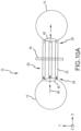
- heat exchanger 10 may be similar to HEX 400.
- heat exchanger 10 comprises an inlet 12, an outlet 14, one or more tubes, such as plurality of tubes 20, and a baffle 16.
- the plurality of tubes 20 include tube 22.
- Tube 22 comprises a first end 24 and a second end 26.
- First end 24 is coupled to inlet 12.
- Second end 26 is coupled to outlet 14.
- air for cooling may enter inlet 12, travel through hot air flow path 40 into plurality of tubes 20, and exit plurality of tubes 20 into outlet 14.
- baffle 16 may be similar to baffle 436.
- baffle 16 a perspective view of baffle 16 is illustrated in FIG. 10B , in accordance with various embodiments.
- Plurality of tubes 20 are inserted into one or more apertures, such as aperture 28 for example, in baffle 16.
- baffle 16 may be fixed to an adjacent component such as a heat exchanger shroud or other fixed object.
- Cooling air flow path 42 may comprise air which flows across plurality of tubes 20.
- heat may be transferred from air in hot air flow path 40 to air in cooling air flow path 42.
- air entering heat exchanger 10 may comprise a greater temperature than air exiting heat exchanger 10.
- plurality of tubes 20 may extend in the x-direction.
- cooling air flow path 42 may flow generally in the z-direction.
- cooling air flow path 42 and hot air flow path 40 may form a cross-flow.
- cooling air flow path 42 and hot air flow path 40 may comprise a cross-flow, counter-flow, co-flow, or any other type of flow. Stated another way, the orientation of hot air flow path 40 relative to cooling air flow path 42 may be in any direction.
- baffle 16 is made of a cobalt alloy (e.g., HAYNES 188) suitable to create an oxidized layer when exposed to temperatures that exceed 1,000°F (538°C) degrees.
- Baffle 16 is configured to form an oxidized layer 30 over an outer surface, such as aperture 28, of the baffle in response to an increase in temperature.
- the oxidized layer 30 provides a lubricating surface over which plurality of tubes 20 may easily slide across.
- tube 22 may expand or contract in an axial direction (x-direction in FIG. 10A ) in response to an increase or decrease, respectively, in temperature.
- Oxidized layer 30 may prevent or lessen stress in heat exchanger 10 during expansion and/or contraction.
Landscapes
- Engineering & Computer Science (AREA)
- Mechanical Engineering (AREA)
- General Engineering & Computer Science (AREA)
- Chemical & Material Sciences (AREA)
- Combustion & Propulsion (AREA)
- Physics & Mathematics (AREA)
- Thermal Sciences (AREA)
- Heat-Exchange Devices With Radiators And Conduit Assemblies (AREA)
- Solid-Phase Diffusion Into Metallic Material Surfaces (AREA)
Description
- The present disclosure relates to gas turbine engines, and, more specifically, to heat exchangers (HEX) for cooling air of gas turbine engines.
- As higher pressures are achieved in compressors of gas turbine engines, the temperature of compressed air in and/or leaving the compressors may increase as well. As a result, various components in a gas turbine engine may experience thermal stress. Thus, a heat exchanger (HEX) may be provided to cool hot air in a gas turbine engine.
- A prior art heat exchanger having the features of the preamble to claim 1 is disclosed in
US 4,528,733 . - The present invention provides a heat exchanger for a gas turbine engine according to claim 1.
- In an embodiment of the above, the lubricating surface may be configured to allow the tube to easily slide across the lubricating surface in response to at least one of an increase and decrease in temperature.
- The subject matter of the present disclosure is particularly pointed out and distinctly claimed in the concluding portion of the specification. A more complete understanding of the present disclosure, however, may best be obtained by referring to the detailed description and claims when considered in connection with the figures, wherein like numerals denote like elements.
-
FIG. 1 illustrates a cross-sectional view of an exemplary gas turbine engine, in accordance with various embodiments; -
FIG. 2 illustrates a cross-sectional view of an exemplary gas turbine engine, in accordance with various embodiments; -
FIG. 3 illustrates the primary-flow gas path in a gas turbine engine through the low pressure compressor, high-pressure compressor, combustor, high-pressure turbine, and low-pressure turbine, in accordance with various embodiments; -
FIG. 4 illustrates a cross-sectional view of a heat exchanger, in accordance with various embodiments; -
FIG. 5 illustrates a cross-sectional view of a heat exchanger, in accordance with various embodiments; -
FIG. 6 illustrates a cross-sectional view of a central manifold, in accordance with various embodiments; -
FIG. 7A illustrates a cross-sectional view of part of a central manifold with tubes installed in a stepped manner, in accordance with various embodiments; -
FIG. 7B illustrates a cross-sectional view of part of a central manifold with tubes installed with a smooth change in radial position, in accordance with various embodiments; -
FIG. 8 illustrates a cross-sectional view of a cooling air flow path through heat exchanger tubes installed in an alternating manner, in accordance with various embodiments; -
FIG. 9 illustrates a perspective view of a heat exchanger installed on a gas turbine engine, in accordance with various embodiments; -
FIG. 10A illustrates a cross-section view of a heat exchanger, in accordance with various embodiments; -
FIG. 10B illustrates a perspective view of a baffle for a heat exchanger, in accordance with various embodiments; and -
FIG. 10C illustrates a baffle with a oxidized layer, in accordance with various embodiments. - The detailed description of exemplary embodiments herein makes reference to the accompanying drawings, which show exemplary embodiments by way of illustration. While these exemplary embodiments are described in sufficient detail to enable those skilled in the art to practice the invention, it should be understood that other embodiments may be realized and that logical changes and adaptations in design and construction may be made in accordance with this invention and the teachings herein. Thus, the detailed description herein is presented for purposes of illustration only and not of limitation. As used herein, "aft" refers to the direction associated with the tail (e.g., the back end) of an aircraft, or generally, to the direction of exhaust of the gas turbine. As used herein, "forward" refers to the direction associated with the nose (e.g., the front end) of an aircraft, or generally, to the direction of flight or motion. As used herein, "gas" and "air" may be used interchangeably.
- Fuel efficiency of gas turbine engines is known to be proportional to the ratio of the exit pressure and the inlet pressure of the engine, or overall pressure ratio (OPR). As the OPR increases, the efficiency of the engine generally increases. However, a byproduct of OPR is high operating temperatures in various portions of the engine, such as the high pressure compressor for example. Materials used in gas turbine engines have temperature thresholds which cannot be surpassed for successful operation. Cooling air may be used to decrease operating temperatures of various components in a gas turbine engine. Generally, air from a compressor section of a gas turbine engine is used to cool other sections of the engine. However, as the OPR of gas turbine engines increases, the air from the compressor section may become increasingly hot. A heat exchanger (HEX) may be used to cool the air from a compressor section, thus providing cooled cooling air.
-
FIG. 1 illustrates a schematic view of a gas turbine engine, in accordance with various embodiments.Gas turbine engine 110 may includecore engine 120. Core air flow C flows throughcore engine 120 and is expelled throughexhaust outlet 118 surroundingtail cone 122. -
Core engine 120 drives afan 114 arranged in a bypass flow path B. Air in bypass flow-path B flows in the aft direction (z-direction) along bypass flow-path B. At least a portion of bypass flow path B may be defined bynacelle 112 and inner fixed structure (IFS) 126.Fan case 132 may surroundfan 114.Fan case 132 may be housed withinfan nacelle 112. - With momentary reference to
FIG. 2 ,nacelle 112 typically comprises two halves which are typically mounted topylon 270.Fan case structure 233 may provide structure for securinggas turbine engine 110 to a pylon 160. According to various embodiments,multiple guide vanes 116 may extend radially betweencore engine 120 and IMC 134. -
Upper bifurcation 144 andlower bifurcation 142 may extend radially between thenacelle 112 and IFS 126 in locations opposite one another to accommodate engine components such as wires and fluids, for example. - Inner
fixed structure 126 surroundscore engine 120 and providescore compartments 128. Various components may be provided incore compartment 128 such as fluid conduits and/or acompressed air duct 130, for example. Compressedair duct 130 may be under high pressure and may supply compressed cooling air from a compressor stage to a high pressure turbine stage, for example. In various embodiments, a heat exchanger may be coupled to compressedair duct 130. - With respect to
FIG. 2 , elements with like element numbering as depicted inFIG. 1 are intended to be the same and will not necessarily be repeated for the sake of clarity. - In various embodiments and with reference to
FIG. 2 , agas turbine engine 110 is provided.Gas turbine engine 110 may be a two-spool turbofan that generally incorporates afan section 222, acompressor section 224, acombustor section 226 and aturbine section 228. Alternative engines may include, for example, an augmentor section among other systems or features. In operation,fan section 222 can drive air along a bypass flow-path B whilecompressor section 224 can drive air along a core flow-path C for compression and communication intocombustor section 226 then expansion throughturbine section 228. Although depicted as a turbofangas turbine engine 110 herein, it should be understood that the concepts described herein are not limited to use with turbofans as the teachings may be applied to other types of turbine engines including three-spool architectures. -
Gas turbine engine 110 may generally comprise alow speed spool 230 and ahigh speed spool 232 mounted for rotation about an engine central longitudinal axis A-A' relative to an enginestatic structure 236 via one or more bearing systems 238 (shown as bearing system 238-1 and bearing system 238-2 inFIG. 2 ). It should be understood that various bearingsystems 238 at various locations may alternatively or additionally be provided including, for example,bearing system 238, bearing system 238-1, and bearing system 238-2. -
Low speed spool 230 may generally comprise aninner shaft 240 that interconnects afan 114, a low pressure (or first)compressor section 244 and a low pressure (or first)turbine section 246.Inner shaft 240 may be connected to fan 114 through a gearedarchitecture 248 that can drivefan 114 at a lower speed thanlow speed spool 230.Geared architecture 248 may comprise agear assembly 260 enclosed within agear housing 262.Gear assembly 260 couplesinner shaft 240 to a rotating fan structure.High speed spool 232 may comprise anouter shaft 250 that interconnects a high-pressure compressor ("HPC") 252 (e.g., a second compressor section) and high pressure (or second)turbine section 254. Acombustor 256 may be located betweenHPC 252 andhigh pressure turbine 254. Amid-turbine frame 257 of enginestatic structure 236 may be located generally betweenhigh pressure turbine 254 andlow pressure turbine 246.Mid-turbine frame 257 may support one ormore bearing systems 238 inturbine section 228.Inner shaft 240 andouter shaft 250 may be concentric and rotate via bearingsystems 238 about the engine central longitudinal axis A-A', which is collinear with their longitudinal axes. As used herein, a "high pressure" compressor or turbine experiences a higher pressure than a corresponding "low pressure" compressor or turbine. - The core airflow C may be compressed by
low pressure compressor 244 thenHPC 252, mixed and burned with fuel incombustor 256, then expanded overhigh pressure turbine 254 andlow pressure turbine 246.Mid-turbine frame 257 includesairfoils 259 which are in the core airflow path.Low pressure turbine 246 andhigh pressure turbine 254 rotationally drive the respectivelow speed spool 230 andhigh speed spool 232 in response to the expansion. -
Gas turbine engine 110 may be, for example, a high-bypass geared aircraft engine. In various embodiments, the bypass ratio ofgas turbine engine 110 may be greater than about six (6). In various embodiments, the bypass ratio ofgas turbine engine 110 may be greater than ten (10). In various embodiments, gearedarchitecture 248 may be an epicyclic gear train, such as a star gear system (sun gear in meshing engagement with a plurality of star gears supported by a carrier and in meshing engagement with a ring gear) or other gear system.Geared architecture 248 may have a gear reduction ratio of greater than about 2.3 andlow pressure turbine 246 may have a pressure ratio that is greater than about 5. In various embodiments, the bypass ratio ofgas turbine engine 110 is greater than about ten (10:1). In various embodiments, the diameter offan 114 may be significantly larger than that of thelow pressure compressor 244, and thelow pressure turbine 246 may have a pressure ratio that is greater than about 5:1.Low pressure turbine 246 pressure ratio may be measured prior to inlet oflow pressure turbine 246 as related to the pressure at the outlet oflow pressure turbine 246 prior to an exhaust nozzle. It should be understood, however, that the above parameters are exemplary of various embodiments of a suitable geared architecture engine and that the present disclosure contemplates other gas turbine engines including direct drive turbofans.FIG. 1 andFIG. 2 provide a general understanding of the sections in a gas turbine engine, and is not intended to limit the disclosure. The present disclosure may extend to all types of turbine engines, including turbofan gas turbine engines and turbojet engines, for all types of applications. - With respect to
FIG. 3 , elements with like element numbering as depicted inFIG. 1 andFIG. 2 are intended to be the same and will not necessarily be repeated for the sake of clarity. -
FIG. 3 illustrates the primary flow gas path throughcore engine 110, in accordance with various embodiments.Core engine 110 may include enginestatic structure 236, low-pressure compressor 244, high-pressure compressor 252,combustor 256, high-pressure turbine 254, and low-pressure turbine C. Enginestatic structure 236 may be referred to as an engine case. Gas may flow into low-pressure compressor 244 along gas path C. Gas flowing through low-pressure compressor 244 along gas path C may be compressed, resulting in an increase in pressure and temperature relative to the pressure and temperature upon entering low-pressure compressor 244. Gas may flow into high-pressure compressor 252 along gas path C. Gas flowing through high-pressure compressor 252 along gas path C may be compressed, resulting in an increase in pressure and temperature relative to the pressure and temperature upon entering high-pressure compressor 252. Uncombusted gas in gas path C leaving high-pressure compressor 252 may be referred to as T3 gas. T3 gas may have a varying temperature at different engine speeds. The temperature of T3 gas may be about 400°F (205°C) whencore engine 110 is at idle speeds and may reach about 1,400°F (760°C) or higher ascore engine 110 accelerates for takeoff, where the term "about" in this context only may refer to +/- 200°F (+/- 111°C). Different engines may have higher temperatures or lower temperatures at each stage. T3 gas may be present atlocation 314 ofcore engine 110. T3 gas leaving the high-pressure compressor 252 may then flow intocombustor 256 to supplycombustor 256 with air for combustion. - In various embodiments, uncombusted T3 gas may be mixed with fuel and burned in
combustor 256. Combusted gas incombustor 256 may be referred to as T4 gas. T4 gas may leavecombustor 256 and enter high-pressure turbine 254. T4 gas may reach or exceed temperatures of up to 3,500°F (1,925°C) or higher. T4 gas may be located atlocation 316, for example. T4 gas leaving combustor may follow gas path C to drive high-pressure turbine 254. - In various embodiments, combusted gas that has entered, but not exited, high-
pressure turbine 254 may be identified as T4.25 gas. T4.25 gas may be significantly cooler than T4gas exiting combustor 256. For example, T4.25 gas may be at temperatures of about 1,000°F-2,000°F (537°C-1,093°C), where the term "about" in this context only may refer to +/- 500°F (+/- 278°C). T4.25 gas may be located atlocation 318, for example. The T4.25 gas then follows out high-pressure turbine 254 and into low-pressure turbine 246 along gas path C. - In various embodiments, combusted gas exiting high-
pressure turbine 254 and entering low-pressure turbine 246 may be referred to as T4.5 gas. T4.5 gas may be cooler than T4.25 gas found in the high-pressure compressor or T4 gas exiting the combustor. For example, T4.5 gas may be about 1,500°F (815°C) degrees at idle, where the term "about" in this context only may refer to +/- 500°F (+/- 278°C). T4.5 gas may be located atlocation 320 in gas path C, for example. The T4.5 gas then follows gas path C into low-pressure turbine 246. - With reference to
FIG. 4 , a cross-section view of a heat exchanger (HEX) 400 is illustrated. An x-y-z axis is provided for ease of illustration. In various embodiments,HEX 400 may comprise acentral manifold 410 and a plurality oftubes 430. In various embodiments,central manifold 410 may comprise aninlet portion 412, afirst outlet portion 414, and asecond outlet portion 416. In various embodiments,first outlet portion 414 may be located on the opposite side ofinlet portion 412 assecond outlet portion 416. In various embodiments,first outlet portion 414 may be located adjacent to inlet portion 412 (in the positive y-direction). In various embodiments,second outlet portion 416 may be located adjacent to inlet portion 412 (in the negative y-direction). In various embodiments,inlet portion 412,first outlet portion 414, andsecond outlet portion 416 may each individually define a cylindrical void. In various embodiments,HEX 400 may further comprise ashroud 450. In various embodiments,shroud 450 may be coupled tocentral manifold 410.Shroud 450 may at least partially encasecentral manifold 410 andtubes 430. - In various embodiments, a plurality of baffles, such as
baffle 436 for example, may be coupled to plurality oftubes 430.Baffle 436 may comprise a plurality of apertures into which plurality oftubes 430 are inserted.Baffle 436 may add to the stiffness of plurality oftubes 430. In various embodiments, with momentary reference toFIG. 1 , the number of baffles installed over plurality oftubes 430 may be determined by the highest operating frequency ofgas turbine engine 110. For example, baffles, such asbaffle 436 may be installed over plurality oftubes 430 until the natural frequency of plurality oftubes 430 is higher than the highest operating frequency ofgas turbine engine 110. In various embodiments, abaffle support 438 may be coupled to baffle 436. - With reference now to
FIG. 3 andFIG. 4 , in various embodiments,central manifold 410 and/or plurality oftubes 430 may be made of a high performance nickel-chromium alloy such as an austenitic nickel-chromium-based superalloy (e.g., INCONEL or HAYNES 282), metals, ceramics, or other materials suitable to withstand T3 gas temperatures that may exceed 1,100°F (593°C) degrees whencore engine 120 is operating at takeoff speeds. - With respect to
FIG. 5 ,FIG. 6 ,FIG. 7A, FIG. 7B , andFIG. 8 , elements with like element numbering as depicted inFIG. 4 are intended to be the same and will not necessarily be repeated for the sake of clarity. - With reference now to
FIG. 5 ,inlet portion 412 may comprise four quadrants including quadrant 502 (also referred to herein as "first quadrant"), quadrant 504 (also referred to herein as "second quadrant"), quadrant 506 (also referred to herein as "third quadrant"), and quadrant 508 (also referred to herein as "fourth quadrant").First outlet portion 414 may comprisefirst half 512 andsecond half 514.Second outlet portion 416 may comprisefirst half 522 andsecond half 524. In various embodiments, a plurality of tubes, includingtube 432, may be coupled betweenquadrant 504 ofinlet portion 412 andsecond half 514 offirst outlet portion 414. In various embodiments, a plurality of tubes, includingtube 434, may be coupled betweenquadrant 508 ofinlet portion 412 andsecond half 524 ofsecond outlet portion 416. In various embodiments, a plurality of tubes, includingtube 536, may be coupled betweenquadrant 502 ofinlet portion 412 andfirst half 512 offirst outlet portion 414. In various embodiments, a plurality of tubes, includingtube 538, may be coupled betweenquadrant 506 ofinlet portion 412 andfirst half 522 ofsecond outlet portion 416. Accordingly,inlet portion 412 may be in fluid communication withfirst outlet portion 414 and in fluid communication withsecond outlet portion 416. In various embodiments,central manifold 410 may comprise a hexagonal geometry as illustrated inFIG. 5 . In various embodiments,central manifold 410 may comprise an octagonal, square, ovular, elliptical, and/or any other geometry. - In various embodiments, as illustrated in
FIG. 5 ,tube 536 may comprise astraight portion 596 and arounded portion 598. Accordingly,tube 536 may be folded, in half for example. Thus, HEX may be referred to as having a folded tube design. - In various embodiments, plurality of
tubes 430 may comprise an upper stack (also referred to herein as "first stack") 590 and a lower stack (also referred to herein as a "second stack") 592. In various embodiments, with momentary reference toFIG. 4 andFIG. 8 ,baffle support 438 may be configured to block air in cooling air flow path F from entering the void 563 located in the middle ofupper stack 590 of plurality oftubes 430. In various embodiments,baffle support 438 may provide support for a plurality of baffles such asbaffle 436. In various embodiments,baffle support 438 may comprise a plurality of apertures, such asaperture 439, through which at least a portion of a plurality of baffles, such as a portion ofbaffle 436, may be inserted and coupled to bafflesupport 438. In various embodiments,baffle support 438 may be welded, soldered, brazed, or otherwise suitably coupled to baffle 436. One or more baffle supports may be located within the void in the middle oflower stack 592 in a similar manner asbaffle support 438. - With reference now to
FIG. 4 ,inlet portion 412 may include afirst attachment feature 442 and asecond attachment feature 444. In various embodiments,first attachment feature 442 may define a hemispherical void. In various embodiments,second attachment feature 444 may define a hemispherical void. In various embodiments,first attachment feature 442 may be detachably coupled toinlet portion 412. In various embodiments,first attachment feature 442 may be permanently coupled toinlet portion 412. For example,first attachment feature 442 may be welded, soldered, brazed, or otherwise suitably coupled toinlet portion 412. In various embodiments,second attachment feature 444 may be detachably coupled toinlet portion 412. In various embodiments,second attachment feature 444 may be permanently coupled toinlet portion 412. For example,second attachment feature 444 may be welded, soldered, brazed, or otherwise suitably coupled toinlet portion 412. - In various embodiments, air may enter
HEX 400 viainlet tube 404. In various embodiments,HEX 400 may be coupled viainlet tube 404 to a high pressure compressor such as high-pressure compressor 252 ofFIG. 2 andFIG. 3 . Accordingly,HEX 400 may be in fluid communication viainlet portion 412 with acompressor section 224 of a gas turbine engine. In various embodiments,HEX 400 may be coupled viainlet tube 404 to a compressor section, combustor section, and/or a turbine section of a gas turbine engine. In various embodiments,HEX 400 may be coupled to any portion of a gas turbine engine. - In various embodiments,
HEX 400 may comprise hot air flow path E. Hot air flow path E may be defined byinlet portion 412, plurality oftubes 430,first outlet portion 414, and/orsecond outlet portion 416. Upon enteringinlet portion 412 viainlet tube 404, air may follow hot air flow path E and enter the plurality oftubes 430 frominlet portion 412 and then exit the plurality oftubes 430 into one offirst outlet portion 414 and/orsecond outlet portion 416. For example, air may enterinlet portion 412, then entertube 432, next it may exittube 432 intofirst outlet portion 414, and finally exitfirst outlet portion 414 viafirst outlet tube 406. In a further example, air may enterinlet portion 412, then entertube 434, next it may exittube 434 intosecond outlet portion 416, and finally exitsecond outlet portion 416 viasecond outlet tube 408. Air exiting eitherfirst outlet portion 414 orsecond outlet portion 416 may be used to cool various portions of a gas turbine engine. In various embodiments, while in plurality oftubes 430, air in hot air flow path E may transfer heat to air in cooling air flow path F. - In various embodiments,
inner surface 454 ofshroud 450 may at least partially define a cooling air flow pathF. Outer surface 418 ofcentral manifold 410 may at least partially define cooling air flow path F. The outer surface of the plurality oftubes 430 may at least partially define cooling air flow path F. In various embodiments, air from bypass flow path 124 ofFIG. 1 may enter cooling air flow path F. In various embodiments, air in cooling air flow path F may flow generally in an aft direction (positive z-direction). In various embodiments, heat from air in the plurality oftubes 430 may be transferred to air in cooling air flow path F. In various embodiments, the transfer of heat may occur in a convective manner. Accordingly, the temperature of air ininlet portion 412 may be greater than the temperature of air infirst outlet portion 414 andsecond outlet portion 416. In various embodiments, the flow of air in plurality oftubes 430 may be orthogonal to the flow of air in cooling air flow path F. Thus, the flow of air intubes 430 and the flow of air in cooling air flow path F may comprise a cross-flow. Accordingly, plurality oftubes 430 may extend in a direction which is orthogonal to cooling air flow path F. - In various embodiments, a pressure gradient may exist between air in hot air flow path E and cooling air flow path F. In various embodiments, as previously mentioned,
inlet portion 412,first outlet portion 414, andsecond outlet portion 416 may each individually define a cylindrical void as shown inFIG. 4 andFIG. 5 . In various embodiments, air pressure ininlet portion 412 may reach up to 500 pounds per square inch absolute (500 psia) (3,447,378.6 Pascal) or more, while air pressure in cooling air flow path F may generally vary between 14.7 psia (101,352.9 Pascal) and 21 psia (144,789.9 Pascal). In various embodiments, the cylindrical geometry ofinlet portion 412,first outlet portion 414, andsecond outlet portion 416 may be ideal to handle the amount of pressure experienced by these portions. In various embodiments, air entering hot air flow path E may reach temperatures of about 1,400°F (760°C) or higher. In various embodiments, with reference toFIG. 3 , air entering hot air flow path E may comprise T3 gas. In various embodiments, air entering cooling air flow path F may reach temperatures of about 100°F (38°C) or higher. In various embodiments, air entering cooling air flow path F may comprise engine bypass air. In various embodiments, engine bypass air may comprise air from bypass flow path 124 ofFIG. 1 . - With reference to
FIG. 8 , cross-section view of plurality oftubes 430 installed in an alternating manner with a detailed view of cooling air flow path F is illustrated, according to various embodiments. An x-y-z axis is provided for ease of illustration. In various embodiments, plurality oftubes 430 may be installed in an alternating manner. For example,column 804 of plurality oftubes 430 may be offset (in the y-direction) fromcolumn 802 such thatcolumn 804 is not directly behind (in the z-direction)column 802. Installingtubes 430 in an alternating manner may aide in more efficiently transferring heat from air in plurality oftubes 430 to air in flow path F. - In various embodiments,
shroud 450 may includeflow tab 452. In various embodiments,flow tab 452 may comprise a tab or panel. In various embodiments,flow tab 452 may be configured to contain cooling air flow path F in close proximity to plurality oftubes 430 which may aide in more efficiently transferring heat from air in plurality oftubes 430 to air in flow path F. - With reference to
FIG. 6 , a cross-section view of acentral manifold 410 is illustrated. An x-y-z axis is provided for ease of illustration. In various embodiments,central manifold 410 may comprise one or more relief cuts 670. Relief cut 670 may be located betweeninlet portion 412 andfirst outlet portion 414. Relief cut 670 may be located betweeninlet portion 412 andsecond outlet portion 416. Relief cut 670 may be configured to relieve stress fromcentral manifold 410 ascentral manifold 410 expands and contracts in response to an increase and decrease in temperature respectively. In various embodiments,central manifold 410 may comprise a plurality ofapertures 660 such asaperture 662 for example. With momentary reference toFIG. 4 , plurality ofapertures 660 may be configured to receive plurality oftubes 430. Plurality oftubes 430 may be inserted from an outer surface 666 ofcentral manifold 410 to aninner surface 668 ofcentral manifold 410 in the x-direction. In various embodiments, plurality oftubes 430 may be detachably coupled tocentral manifold 410. In various embodiments, plurality oftubes 430 may be permanently coupled tocentral manifold 410. For example,tube 432 may be welded, soldered, brazed, or otherwise suitably coupled tocentral manifold 410 viaaperture 662. In various embodiments, plurality oftubes 430 may be flush withinner surface 668 when in an installed position. In various embodiments, plurality oftubes 430 may protrude radially inward frominner surface 668 when in an installed position. - With reference to
FIG. 7A , plurality oftubes 430 are illustrated in an installed position in a stepped fashion, according to various embodiments. Plurality oftubes 430 may comprise various sections of tubes, each installed at different radial positions. For example, plurality oftubes 430 may comprise various sections of tubes such assection 702,section 704, andsection 706. In various embodiments,section 702 may protrude further radially inward thansection 704. In various embodiments,section 704 may protrude further radially inward thansection 706. In various embodiments, with momentary reference toFIG. 7B , plurality oftubes 430 may comprise a gradual or smooth change in radial position as illustrated inFIG. 7B , as opposed to a stepped change as illustrated inFIG. 7A . In various embodiments,inlet portion 412 may comprise a pressure gradient along the axial direction (z-direction). Installing plurality oftubes 430 in a stepped fashion may compensate for such pressure gradient resulting in a more uniform flow through plurality oftubes 430. In various embodiments, plurality oftubes 430 may be pre-cut to size before installing intocentral manifold 410. In various embodiments, plurality oftubes 430 may be installed intocentral manifold 410 and then cut to length when in the installed position. For example, each tube of plurality oftubes 430 may comprise a similar length, installed intocentral manifold 410, and then cut to various lengths according to pre-determined specifications. In various embodiments, one or more orifices may be coupled to an inlet of plurality oftubes 430 in order to meter the flow of air through plurality oftubes 430. - In various embodiments, each tube included in plurality of
tubes 430 may comprise a physical flow area which is less than 5% of the flow area ofinlet portion 412. With further reference toFIG. 4 ,inlet portion 412 may comprise inner diameter 478, where the flow area ofinlet portion 412 is calculated as πtimes one fourth times inner diameter 478 squared, or (π/4)∗(inner diameter 478)2. Similarly, the inner diameter of each tube included in plurality oftubes 430 may comprise a flow area. For example, according to various embodiments,tube 432 may comprise a flow area which is less than 5% of the flow area ofinlet portion 412. In various embodiments,tube 432 may comprise a flow area in the range from about 1% to about 7% of the flow area ofinlet portion 412, wherein the term "about" in this context can only mean +/- 1%. Minimizing the flow area oftube 432 may allow room for more tubes to be included in plurality oftubes 430, thus increasing the overall surface area of plurality oftubes 430. Increasing the overall surface area of plurality oftubes 430 may increase the rate at which heat may be transferred from air in plurality oftubes 430 to air in cooling air flow path F. Similarly, the flow area offirst outlet portion 414 and the flow area ofsecond outlet portion 416 may be less than the flow area ofinlet portion 412. - In various embodiments,
HEX 400 may be configured such that the flow area ofinlet portion 412 is equal to the flow area offirst outlet portion 414 and the flow area ofsecond outlet portion 416. In various embodiments, two outlets may enable the length of plurality oftubes 430 to be decreased while maintaining similar heat transfer between hot air flow path E and cooling air flow path F, in comparison with a single outlet design. A pressure drop (or difference) may exist betweeninlet portion 412 and bothfirst outlet portion 414 andsecond outlet portion 416. In various embodiments, splitting the flow of hot air flow path E in half betweenfirst outlet portion 414 andsecond outlet portion 416 may decrease the pressure drop between the inlet and outlet by half, in comparison with a single outlet design. Stated another way, having two outlets, with hot air flow path E split between the two outlets via plurality oftubes 430, may decrease the pressure drop betweeninlet portion 412 andoutlet portions HEX 400 in order to prevent reverse flow or stagnated flow throughHEX 400. - With respect to
FIG. 9 a heat exchanger (HEX) installed on a gas turbine engine is illustrated, in accordance with various embodiments. In various embodiments,HEX 900 may be similar toHEX 400 as illustrated inFIG. 4 . In various embodiments,HEX 900 may comprise an inlet portion 912,first outlet portion 914,second outlet portion 916, and a plurality of tubes (not shown inFIG. 9 ).HEX 900 may further compriseshroud 950.Inlet tube 904 may be coupled to inlet portion 912 ofHEX 900.First outlet tube 906 may be coupled tofirst outlet portion 914 ofHEX 900.Second outlet tube 908 may be coupled tosecond outlet portion 916 ofHEX 900. - In various embodiments,
HEX 900 may be coupled tocore engine 120 viafirst attachment feature 942 andsecond attachment feature 944. In various embodiments,first attachment feature 942 may be similar tofirst attachment feature 442 as illustrated inFIG. 4 . In various embodiments,second attachment feature 944 may be similar tosecond attachment feature 444 as illustrated inFIG. 4 . In various embodiments,first attachment feature 942 may be coupled tocore engine 120 via one or more links, such asfirst link 920 for example. In various embodiments,first link 920 may be a turnbuckle link.FIG. 9 illustratesfirst attachment feature 942 comprising a plurality of tabs, such astab 943 for example. A bolt or fastener may be inserted through one or more apertures inlink 920 and one or more apertures intab 943 to couple link 920 andfirst attachment feature 942. First link 920 may extend generally in the z-direction.Second link 922 andthird link 924 may be coupled to first attachment feature in a similar manner asfirst link 920.Second link 922 may extend away fromfirst attachment feature 942 generally in the negative x-direction.Third link 924 may extend away fromfirst attachment feature 942 generally in the positive x-direction. Accordingly, first attachment feature may be fixed in space. Stated another way, first attachment feature may be fixed in the x, y, and z-directions. - In various embodiments,
second attachment feature 944 may be coupled tocore engine 120.Second attachment feature 944 may be coupled tocore engine 120 viafourth link 928. In various embodiments,second attachment feature 944 may be coupled tocore engine 120 such thatsecond attachment feature 944 may be free to move in the z-direction. Accordingly,second attachment feature 944 may be configured to freely expand away from or contract towardsfirst attachment feature 942 withHEX 900 in response to an increase or decrease in temperature, respectively. In various embodiments, with momentary reference toFIG. 2 , centerline 998 ofHEX 900 may be oriented at an angle in the range from about zero degrees (0°) to about five degrees (5°), wherein the term "about" in this context can only mean +/- 3°. In various embodiments, centerline 998 ofHEX 900 may be oriented at an angle of about five degrees (5°), wherein the term "about" in this context can only mean +/- 2°. - With reference to
FIG. 10A , a cross-section view of aheat exchanger 10 in accordance with the claims is illustrated. With momentary reference toFIG. 4 ,heat exchanger 10 may be similar toHEX 400. In accordance with the claims,heat exchanger 10 comprises aninlet 12, anoutlet 14, one or more tubes, such as plurality oftubes 20, and abaffle 16. The plurality oftubes 20 includetube 22.Tube 22 comprises afirst end 24 and asecond end 26.First end 24 is coupled toinlet 12.Second end 26 is coupled tooutlet 14. In various embodiments, air for cooling (or hot air) may enterinlet 12, travel through hotair flow path 40 into plurality oftubes 20, and exit plurality oftubes 20 intooutlet 14. With momentary reference toFIG. 4 , baffle 16 may be similar to baffle 436. - With reference to
FIG. 10A andFIG. 10B , a perspective view ofbaffle 16 is illustrated inFIG. 10B , in accordance with various embodiments. Plurality oftubes 20 are inserted into one or more apertures, such asaperture 28 for example, inbaffle 16. In various embodiments, baffle 16 may be fixed to an adjacent component such as a heat exchanger shroud or other fixed object. Coolingair flow path 42 may comprise air which flows across plurality oftubes 20. In various embodiments, heat may be transferred from air in hotair flow path 40 to air in coolingair flow path 42. Thus, air enteringheat exchanger 10 may comprise a greater temperature than air exitingheat exchanger 10. In various embodiments, plurality oftubes 20 may extend in the x-direction. In various embodiments, coolingair flow path 42 may flow generally in the z-direction. Thus, coolingair flow path 42 and hotair flow path 40 may form a cross-flow. However, coolingair flow path 42 and hotair flow path 40 may comprise a cross-flow, counter-flow, co-flow, or any other type of flow. Stated another way, the orientation of hotair flow path 40 relative to coolingair flow path 42 may be in any direction. - In accordance with the claims, with reference to
FIG. 10 C , baffle 16 is made of a cobalt alloy (e.g., HAYNES 188) suitable to create an oxidized layer when exposed to temperatures that exceed 1,000°F (538°C) degrees.Baffle 16 is configured to form an oxidizedlayer 30 over an outer surface, such asaperture 28, of the baffle in response to an increase in temperature. With further reference toFIG. 10A , the oxidizedlayer 30 provides a lubricating surface over which plurality oftubes 20 may easily slide across. For example,tube 22 may expand or contract in an axial direction (x-direction inFIG. 10A ) in response to an increase or decrease, respectively, in temperature. Thus,tube 22 may easily slide throughaperture 28 across oxidizedlayer 30.Oxidized layer 30 may prevent or lessen stress inheat exchanger 10 during expansion and/or contraction.
Claims (2)
- A heat exchanger (400; 900) for a gas turbine engine (110) comprising:a baffle (436, 16);a tube (22) inserted at least partially through the baffle (436, 16); and characterised by an inlet (12) coupled to a first end of the tube (22); and byan outlet (14) coupled to a second end of the tube (22); and in thatthe baffle (436, 16) comprises a cobalt alloy configured to form an oxidized layer (30) over an outer surface of the baffle (436, 16) in response to an increase in temperature, the oxidized layer providing a lubricating surface.
- The heat exchanger of claim 1, wherein the lubricating surface is configured to allow the tube (22) to easily slide across the lubricating surface in response to at least one of an increase and decrease in temperature.
Applications Claiming Priority (2)
| Application Number | Priority Date | Filing Date | Title |
|---|---|---|---|
| US14/826,905 US10287982B2 (en) | 2015-08-14 | 2015-08-14 | Folded heat exchanger for cooled cooling air |
| EP16182828.0A EP3139025B1 (en) | 2015-08-14 | 2016-08-04 | Folded heat exchanger for cooled cooling air |
Related Parent Applications (2)
| Application Number | Title | Priority Date | Filing Date |
|---|---|---|---|
| EP16182828.0A Division EP3139025B1 (en) | 2015-08-14 | 2016-08-04 | Folded heat exchanger for cooled cooling air |
| EP16182828.0A Division-Into EP3139025B1 (en) | 2015-08-14 | 2016-08-04 | Folded heat exchanger for cooled cooling air |
Publications (3)
| Publication Number | Publication Date |
|---|---|
| EP3680478A2 EP3680478A2 (en) | 2020-07-15 |
| EP3680478A3 EP3680478A3 (en) | 2020-10-14 |
| EP3680478B1 true EP3680478B1 (en) | 2023-04-12 |
Family
ID=56851373
Family Applications (2)
| Application Number | Title | Priority Date | Filing Date |
|---|---|---|---|
| EP16182828.0A Active EP3139025B1 (en) | 2015-08-14 | 2016-08-04 | Folded heat exchanger for cooled cooling air |
| EP20156729.4A Active EP3680478B1 (en) | 2015-08-14 | 2016-08-04 | Heat exchanger for gas turbine engine |
Family Applications Before (1)
| Application Number | Title | Priority Date | Filing Date |
|---|---|---|---|
| EP16182828.0A Active EP3139025B1 (en) | 2015-08-14 | 2016-08-04 | Folded heat exchanger for cooled cooling air |
Country Status (2)
| Country | Link |
|---|---|
| US (2) | US10287982B2 (en) |
| EP (2) | EP3139025B1 (en) |
Families Citing this family (14)
| Publication number | Priority date | Publication date | Assignee | Title |
|---|---|---|---|---|
| US20170045309A1 (en) * | 2015-08-11 | 2017-02-16 | Hamilton Sundstrand Corporation | High temperature flow manifold |
| US11092384B2 (en) * | 2016-01-14 | 2021-08-17 | Hamilton Sundstrand Corporation | Thermal stress relief for heat sinks |
| US10526916B2 (en) * | 2016-04-26 | 2020-01-07 | United Technologies Corporation | Heat exchanger with heat resistant center body |
| SI3355022T1 (en) * | 2017-01-31 | 2020-02-28 | Alfa Laval Corporate Ab | Apparatus and method for protecting the tube-sheet of a syngas loop boiler |
| EP3413001B1 (en) * | 2017-06-06 | 2020-01-08 | Ge Avio S.r.l. | Additively manufactured heat exchanger |
| US11306979B2 (en) * | 2018-12-05 | 2022-04-19 | Hamilton Sundstrand Corporation | Heat exchanger riblet and turbulator features for improved manufacturability and performance |
| FR3095264B1 (en) * | 2019-04-17 | 2021-03-19 | Safran Aircraft Engines | Secondary air / fluid heat exchanger, its manufacturing process and bypass turbomachine equipped with this exchanger |
| US11378341B2 (en) * | 2020-01-03 | 2022-07-05 | Raytheon Technologies Corporation | Gas turbine engine heat exchanger for annular flowpaths |
| CN113090390B (en) * | 2021-04-07 | 2022-02-08 | 南京航空航天大学 | Precooling type engine air inlet channel with bypass flow path and design method |
| US11859910B2 (en) | 2021-05-14 | 2024-01-02 | Rtx Corporation | Heat exchanger tube support |
| US11892250B2 (en) * | 2021-05-14 | 2024-02-06 | Rtx Corporation | Heat exchanger tube support |
| CA3188310A1 (en) * | 2022-02-17 | 2023-08-17 | Bosal Flanders NV | Heat exchanger module, method for manufacturing such a module and tubular heat exchanger comprising such modules |
| CN115853644B (en) * | 2022-12-06 | 2025-03-25 | 南京航空航天大学 | A serially arranged dual inlet duct-precooler structure and its design method |
| US12234771B1 (en) | 2023-07-31 | 2025-02-25 | Rolls-Royce North American Technologies Inc. | Bypass duct heat exchanger mount system with reduced motion |
Family Cites Families (35)
| Publication number | Priority date | Publication date | Assignee | Title |
|---|---|---|---|---|
| GB533048A (en) | 1939-10-02 | 1941-02-05 | Ribbesford Company Ltd | Improvements in or relating to shock absorbers |
| US3117624A (en) | 1959-06-22 | 1964-01-14 | Separator Ab | Plate heat exchanger |
| US3770290A (en) | 1972-01-24 | 1973-11-06 | F Bottalico | Vehicle shock absorber |
| US4120150A (en) * | 1977-05-17 | 1978-10-17 | The United States Of America As Represented By The Secretary Of The Air Force | Compact fuel-to-air heat exchanger for jet engine application |
| US4187675A (en) * | 1977-10-14 | 1980-02-12 | The United States Of America As Represented By The Secretary Of The Air Force | Compact air-to-air heat exchanger for jet engine application |
| US4457741A (en) | 1979-03-12 | 1984-07-03 | Hoeptner Iii Herbert W | Tensioner |
| US4528733A (en) * | 1983-07-25 | 1985-07-16 | United Aircraft Products, Inc. | Method of making tubular heat exchangers |
| US4901829A (en) | 1988-03-17 | 1990-02-20 | Stone & Webster Engineering Corp. | Frictional shock absorber enclosed within a housing |
| DE3827679A1 (en) * | 1988-08-16 | 1990-02-22 | Mtu Muenchen Gmbh | METHOD FOR PRODUCING A SPACER FOR PROFILE TUBES OF THE MATRIX OF A HEAT EXCHANGER |
| DE3840460A1 (en) * | 1988-12-01 | 1990-06-07 | Mtu Muenchen Gmbh | HEAT EXCHANGER |
| DE4139104C1 (en) | 1991-11-28 | 1993-05-27 | Mtu Muenchen Gmbh | |
| FR2734319B1 (en) * | 1995-05-15 | 1997-07-18 | Aerospatiale | DEVICE FOR TAKING UP AND COOLING HOT AIR AT AN AIRCRAFT ENGINE |
| FR2734320B1 (en) * | 1995-05-15 | 1997-07-18 | Aerospatiale | DEVICE FOR TAKING UP AND COOLING HOT AIR AT AN AIRCRAFT ENGINE |
| US6212974B1 (en) | 1998-12-17 | 2001-04-10 | United Technologies Corporation | Variable stiffness positioning link for a gearbox |
| DE10001112A1 (en) | 2000-01-13 | 2001-07-19 | Alstom Power Schweiz Ag Baden | Cooling air cooler for gas turbine unit, with water separator on cooling air side behind jet device in flow direction |
| DE10031721C1 (en) | 2000-06-29 | 2001-12-13 | Krupp Presta Ag Eschen | Length and height adjustment device for automobile steering column has locking devices for length and height adjustment opened and closed in common by clamping mechanism |
| AT411353B (en) | 2000-10-25 | 2003-12-29 | Sticht Fertigungstech Stiwa | CLUTCH DEVICE, ESPECIALLY FOR AT LEAST TWO RELATIVELY ADJUSTABLE PARTS |
| US6412606B1 (en) | 2001-10-03 | 2002-07-02 | Chun-Liang Wu | Damper/positioning structure |
| US6918598B2 (en) * | 2002-04-02 | 2005-07-19 | Honeywell International, Inc. | Hot air seal |
| US7174804B2 (en) | 2002-12-03 | 2007-02-13 | Associated Spring Raymond | Positioning mechanism for tilt steering |
| JP2005140451A (en) * | 2003-11-07 | 2005-06-02 | Usui Kokusai Sangyo Kaisha Ltd | Heat exchanger tube faced with fin member |
| DE102004047999A1 (en) | 2004-10-01 | 2006-04-06 | BSH Bosch und Siemens Hausgeräte GmbH | Friction damper device for a washing machine |
| FR2889250B1 (en) * | 2005-07-28 | 2007-09-07 | Airbus France Sas | PROPELLER ASSEMBLY FOR AIRCRAFT AND AIRCRAFT COMPRISING AT LEAST ONE SUCH PROPELLER ASSEMBLY |
| JP4807076B2 (en) * | 2005-12-28 | 2011-11-02 | Dowaテクノロジー株式会社 | Heat transfer tube, heat transfer tube manufacturing method, and fluidized bed furnace |
| EP2118611B1 (en) * | 2006-12-14 | 2013-04-17 | Embaffle B.V. | Assembly of baffles and seals |
| FR2944077B1 (en) | 2009-04-06 | 2011-05-06 | Messier Dowty Sa | SLIDING DEVICE WITH CONTROLLED FRICTION, SUCH AS A DAMPER, OPERATING IN BOTH SENSES |
| US8307662B2 (en) | 2009-10-15 | 2012-11-13 | General Electric Company | Gas turbine engine temperature modulated cooling flow |
| US8510945B2 (en) | 2009-12-22 | 2013-08-20 | Unison Industries, Llc | Method of mounting a heat exchanger in a gas turbine engine assembly |
| US9022185B2 (en) | 2010-05-11 | 2015-05-05 | Adil Kanioz | Electromechanical friction shock absorber |
| US8727273B2 (en) | 2010-09-08 | 2014-05-20 | Goodrich Corporation | Shrink shock strut locking mechanism for retractable aircraft landing gear |
| US9395122B2 (en) | 2011-02-28 | 2016-07-19 | Pratt & Whitney Canada Corp. | Diffusing gas turbine engine recuperator |
| WO2015041855A1 (en) | 2013-09-19 | 2015-03-26 | United Technologies Corporation | Aircraft engine case shock mount |
| US10006369B2 (en) * | 2014-06-30 | 2018-06-26 | General Electric Company | Method and system for radial tubular duct heat exchangers |
| JP6413503B2 (en) | 2014-09-01 | 2018-10-31 | アイシン精機株式会社 | Body reinforcement device |
| DE102016225036A1 (en) | 2016-12-14 | 2018-06-14 | Suspa Gmbh | Friction device and friction damper with such a friction device |
-
2015
- 2015-08-14 US US14/826,905 patent/US10287982B2/en active Active
-
2016
- 2016-08-04 EP EP16182828.0A patent/EP3139025B1/en active Active
- 2016-08-04 EP EP20156729.4A patent/EP3680478B1/en active Active
-
2019
- 2019-03-26 US US16/364,524 patent/US11492973B2/en active Active
Also Published As
| Publication number | Publication date |
|---|---|
| EP3680478A2 (en) | 2020-07-15 |
| EP3139025B1 (en) | 2020-04-01 |
| US20170044983A1 (en) | 2017-02-16 |
| EP3139025A3 (en) | 2017-05-17 |
| US10287982B2 (en) | 2019-05-14 |
| EP3680478A3 (en) | 2020-10-14 |
| EP3139025A2 (en) | 2017-03-08 |
| US20190218974A1 (en) | 2019-07-18 |
| US11492973B2 (en) | 2022-11-08 |
Similar Documents
| Publication | Publication Date | Title |
|---|---|---|
| EP3680478B1 (en) | Heat exchanger for gas turbine engine | |
| US11572928B2 (en) | Heat exchanger for cooled cooling air with adjustable damper | |
| EP3130781B1 (en) | Heat exchanger for cooled cooling air | |
| EP3889535B1 (en) | Duct mounted heat exchanger | |
| US20170204787A1 (en) | Heat exchanger array | |
| EP3246544B1 (en) | Gas turbine engine having a heat exchanger suspension system with pipe-to-linkage spring rate ratio | |
| EP2770190A2 (en) | Exhaust section for bypass gas turbine engines | |
| US10526916B2 (en) | Heat exchanger with heat resistant center body | |
| EP4403753A2 (en) | Tube bank heat exchanger | |
| EP3252420B1 (en) | Heat exchanger with precision manufactured flow passages | |
| EP3193038B1 (en) | Heat exchanger for cooled cooling air with adjustable damper | |
| EP3722723A1 (en) | Curved heat exchanger | |
| EP4089356B1 (en) | Heat exchanger tube support | |
| EP3102808B1 (en) | Gas turbine engine with cooling fluid composite tube | |
| EP4407170A1 (en) | Lattice heat exchanger | |
| US12298091B2 (en) | Heat exchanger with header embedded cooling channels | |
| EP3848570B1 (en) | Cooling system for a gas turbine engine |
Legal Events
| Date | Code | Title | Description |
|---|---|---|---|
| PUAI | Public reference made under article 153(3) epc to a published international application that has entered the european phase |
Free format text: ORIGINAL CODE: 0009012 |
|
| STAA | Information on the status of an ep patent application or granted ep patent |
Free format text: STATUS: THE APPLICATION HAS BEEN PUBLISHED |
|
| AC | Divisional application: reference to earlier application |
Ref document number: 3139025 Country of ref document: EP Kind code of ref document: P |
|
| AK | Designated contracting states |
Kind code of ref document: A2 Designated state(s): AL AT BE BG CH CY CZ DE DK EE ES FI FR GB GR HR HU IE IS IT LI LT LU LV MC MK MT NL NO PL PT RO RS SE SI SK SM TR |
|
| PUAL | Search report despatched |
Free format text: ORIGINAL CODE: 0009013 |
|
| AK | Designated contracting states |
Kind code of ref document: A3 Designated state(s): AL AT BE BG CH CY CZ DE DK EE ES FI FR GB GR HR HU IE IS IT LI LT LU LV MC MK MT NL NO PL PT RO RS SE SI SK SM TR |
|
| RIC1 | Information provided on ipc code assigned before grant |
Ipc: F02C 7/18 20060101ALI20200908BHEP Ipc: F04D 29/58 20060101ALI20200908BHEP Ipc: F02K 3/115 20060101AFI20200908BHEP Ipc: F02C 7/20 20060101ALI20200908BHEP Ipc: F02C 7/141 20060101ALI20200908BHEP |
|
| RAP1 | Party data changed (applicant data changed or rights of an application transferred) |
Owner name: RAYTHEON TECHNOLOGIES CORPORATION |
|
| STAA | Information on the status of an ep patent application or granted ep patent |
Free format text: STATUS: REQUEST FOR EXAMINATION WAS MADE |
|
| 17P | Request for examination filed |
Effective date: 20210401 |
|
| RBV | Designated contracting states (corrected) |
Designated state(s): AL AT BE BG CH CY CZ DE DK EE ES FI FR GB GR HR HU IE IS IT LI LT LU LV MC MK MT NL NO PL PT RO RS SE SI SK SM TR |
|
| GRAP | Despatch of communication of intention to grant a patent |
Free format text: ORIGINAL CODE: EPIDOSNIGR1 |
|
| STAA | Information on the status of an ep patent application or granted ep patent |
Free format text: STATUS: GRANT OF PATENT IS INTENDED |
|
| INTG | Intention to grant announced |
Effective date: 20221027 |
|
| RIN1 | Information on inventor provided before grant (corrected) |
Inventor name: SCHWARZ, FREDERICK M. Inventor name: DUESLER, PAUL W. |
|
| GRAS | Grant fee paid |
Free format text: ORIGINAL CODE: EPIDOSNIGR3 |
|
| GRAA | (expected) grant |
Free format text: ORIGINAL CODE: 0009210 |
|
| STAA | Information on the status of an ep patent application or granted ep patent |
Free format text: STATUS: THE PATENT HAS BEEN GRANTED |
|
| AC | Divisional application: reference to earlier application |
Ref document number: 3139025 Country of ref document: EP Kind code of ref document: P |
|
| AK | Designated contracting states |
Kind code of ref document: B1 Designated state(s): AL AT BE BG CH CY CZ DE DK EE ES FI FR GB GR HR HU IE IS IT LI LT LU LV MC MK MT NL NO PL PT RO RS SE SI SK SM TR |
|
| REG | Reference to a national code |
Ref country code: GB Ref legal event code: FG4D |
|
| REG | Reference to a national code |
Ref country code: CH Ref legal event code: EP |
|
| REG | Reference to a national code |
Ref country code: DE Ref legal event code: R096 Ref document number: 602016078861 Country of ref document: DE |
|
| REG | Reference to a national code |
Ref country code: IE Ref legal event code: FG4D |
|
| REG | Reference to a national code |
Ref country code: AT Ref legal event code: REF Ref document number: 1559911 Country of ref document: AT Kind code of ref document: T Effective date: 20230515 |
|
| P01 | Opt-out of the competence of the unified patent court (upc) registered |
Effective date: 20230521 |
|
| REG | Reference to a national code |
Ref country code: LT Ref legal event code: MG9D |
|
| REG | Reference to a national code |
Ref country code: NL Ref legal event code: MP Effective date: 20230412 |
|
| REG | Reference to a national code |
Ref country code: AT Ref legal event code: MK05 Ref document number: 1559911 Country of ref document: AT Kind code of ref document: T Effective date: 20230412 |
|
| PG25 | Lapsed in a contracting state [announced via postgrant information from national office to epo] |
Ref country code: NL Free format text: LAPSE BECAUSE OF FAILURE TO SUBMIT A TRANSLATION OF THE DESCRIPTION OR TO PAY THE FEE WITHIN THE PRESCRIBED TIME-LIMIT Effective date: 20230412 |
|
| PG25 | Lapsed in a contracting state [announced via postgrant information from national office to epo] |
Ref country code: SE Free format text: LAPSE BECAUSE OF FAILURE TO SUBMIT A TRANSLATION OF THE DESCRIPTION OR TO PAY THE FEE WITHIN THE PRESCRIBED TIME-LIMIT Effective date: 20230412 Ref country code: PT Free format text: LAPSE BECAUSE OF FAILURE TO SUBMIT A TRANSLATION OF THE DESCRIPTION OR TO PAY THE FEE WITHIN THE PRESCRIBED TIME-LIMIT Effective date: 20230814 Ref country code: NO Free format text: LAPSE BECAUSE OF FAILURE TO SUBMIT A TRANSLATION OF THE DESCRIPTION OR TO PAY THE FEE WITHIN THE PRESCRIBED TIME-LIMIT Effective date: 20230712 Ref country code: ES Free format text: LAPSE BECAUSE OF FAILURE TO SUBMIT A TRANSLATION OF THE DESCRIPTION OR TO PAY THE FEE WITHIN THE PRESCRIBED TIME-LIMIT Effective date: 20230412 Ref country code: AT Free format text: LAPSE BECAUSE OF FAILURE TO SUBMIT A TRANSLATION OF THE DESCRIPTION OR TO PAY THE FEE WITHIN THE PRESCRIBED TIME-LIMIT Effective date: 20230412 |
|
| RAP4 | Party data changed (patent owner data changed or rights of a patent transferred) |
Owner name: RTX CORPORATION |
|
| PG25 | Lapsed in a contracting state [announced via postgrant information from national office to epo] |
Ref country code: RS Free format text: LAPSE BECAUSE OF FAILURE TO SUBMIT A TRANSLATION OF THE DESCRIPTION OR TO PAY THE FEE WITHIN THE PRESCRIBED TIME-LIMIT Effective date: 20230412 Ref country code: PL Free format text: LAPSE BECAUSE OF FAILURE TO SUBMIT A TRANSLATION OF THE DESCRIPTION OR TO PAY THE FEE WITHIN THE PRESCRIBED TIME-LIMIT Effective date: 20230412 Ref country code: LV Free format text: LAPSE BECAUSE OF FAILURE TO SUBMIT A TRANSLATION OF THE DESCRIPTION OR TO PAY THE FEE WITHIN THE PRESCRIBED TIME-LIMIT Effective date: 20230412 Ref country code: LT Free format text: LAPSE BECAUSE OF FAILURE TO SUBMIT A TRANSLATION OF THE DESCRIPTION OR TO PAY THE FEE WITHIN THE PRESCRIBED TIME-LIMIT Effective date: 20230412 Ref country code: IS Free format text: LAPSE BECAUSE OF FAILURE TO SUBMIT A TRANSLATION OF THE DESCRIPTION OR TO PAY THE FEE WITHIN THE PRESCRIBED TIME-LIMIT Effective date: 20230812 Ref country code: HR Free format text: LAPSE BECAUSE OF FAILURE TO SUBMIT A TRANSLATION OF THE DESCRIPTION OR TO PAY THE FEE WITHIN THE PRESCRIBED TIME-LIMIT Effective date: 20230412 Ref country code: GR Free format text: LAPSE BECAUSE OF FAILURE TO SUBMIT A TRANSLATION OF THE DESCRIPTION OR TO PAY THE FEE WITHIN THE PRESCRIBED TIME-LIMIT Effective date: 20230713 Ref country code: AL Free format text: LAPSE BECAUSE OF FAILURE TO SUBMIT A TRANSLATION OF THE DESCRIPTION OR TO PAY THE FEE WITHIN THE PRESCRIBED TIME-LIMIT Effective date: 20230412 |
|
| PG25 | Lapsed in a contracting state [announced via postgrant information from national office to epo] |
Ref country code: FI Free format text: LAPSE BECAUSE OF FAILURE TO SUBMIT A TRANSLATION OF THE DESCRIPTION OR TO PAY THE FEE WITHIN THE PRESCRIBED TIME-LIMIT Effective date: 20230412 |
|
| REG | Reference to a national code |
Ref country code: DE Ref legal event code: R097 Ref document number: 602016078861 Country of ref document: DE |
|
| PG25 | Lapsed in a contracting state [announced via postgrant information from national office to epo] |
Ref country code: SK Free format text: LAPSE BECAUSE OF FAILURE TO SUBMIT A TRANSLATION OF THE DESCRIPTION OR TO PAY THE FEE WITHIN THE PRESCRIBED TIME-LIMIT Effective date: 20230412 |
|
| PG25 | Lapsed in a contracting state [announced via postgrant information from national office to epo] |
Ref country code: SM Free format text: LAPSE BECAUSE OF FAILURE TO SUBMIT A TRANSLATION OF THE DESCRIPTION OR TO PAY THE FEE WITHIN THE PRESCRIBED TIME-LIMIT Effective date: 20230412 Ref country code: SK Free format text: LAPSE BECAUSE OF FAILURE TO SUBMIT A TRANSLATION OF THE DESCRIPTION OR TO PAY THE FEE WITHIN THE PRESCRIBED TIME-LIMIT Effective date: 20230412 Ref country code: RO Free format text: LAPSE BECAUSE OF FAILURE TO SUBMIT A TRANSLATION OF THE DESCRIPTION OR TO PAY THE FEE WITHIN THE PRESCRIBED TIME-LIMIT Effective date: 20230412 Ref country code: EE Free format text: LAPSE BECAUSE OF FAILURE TO SUBMIT A TRANSLATION OF THE DESCRIPTION OR TO PAY THE FEE WITHIN THE PRESCRIBED TIME-LIMIT Effective date: 20230412 Ref country code: DK Free format text: LAPSE BECAUSE OF FAILURE TO SUBMIT A TRANSLATION OF THE DESCRIPTION OR TO PAY THE FEE WITHIN THE PRESCRIBED TIME-LIMIT Effective date: 20230412 Ref country code: CZ Free format text: LAPSE BECAUSE OF FAILURE TO SUBMIT A TRANSLATION OF THE DESCRIPTION OR TO PAY THE FEE WITHIN THE PRESCRIBED TIME-LIMIT Effective date: 20230412 |
|
| PLBE | No opposition filed within time limit |
Free format text: ORIGINAL CODE: 0009261 |
|
| STAA | Information on the status of an ep patent application or granted ep patent |
Free format text: STATUS: NO OPPOSITION FILED WITHIN TIME LIMIT |
|
| PG25 | Lapsed in a contracting state [announced via postgrant information from national office to epo] |
Ref country code: MC Free format text: LAPSE BECAUSE OF FAILURE TO SUBMIT A TRANSLATION OF THE DESCRIPTION OR TO PAY THE FEE WITHIN THE PRESCRIBED TIME-LIMIT Effective date: 20230412 |
|
| 26N | No opposition filed |
Effective date: 20240115 |
|
| REG | Reference to a national code |
Ref country code: CH Ref legal event code: PL |
|
| PG25 | Lapsed in a contracting state [announced via postgrant information from national office to epo] |
Ref country code: MC Free format text: LAPSE BECAUSE OF FAILURE TO SUBMIT A TRANSLATION OF THE DESCRIPTION OR TO PAY THE FEE WITHIN THE PRESCRIBED TIME-LIMIT Effective date: 20230412 |
|
| PG25 | Lapsed in a contracting state [announced via postgrant information from national office to epo] |
Ref country code: LU Free format text: LAPSE BECAUSE OF NON-PAYMENT OF DUE FEES Effective date: 20230804 |
|
| PG25 | Lapsed in a contracting state [announced via postgrant information from national office to epo] |
Ref country code: LU Free format text: LAPSE BECAUSE OF NON-PAYMENT OF DUE FEES Effective date: 20230804 Ref country code: CH Free format text: LAPSE BECAUSE OF NON-PAYMENT OF DUE FEES Effective date: 20230831 |
|
| PG25 | Lapsed in a contracting state [announced via postgrant information from national office to epo] |
Ref country code: SI Free format text: LAPSE BECAUSE OF FAILURE TO SUBMIT A TRANSLATION OF THE DESCRIPTION OR TO PAY THE FEE WITHIN THE PRESCRIBED TIME-LIMIT Effective date: 20230412 |
|
| REG | Reference to a national code |
Ref country code: BE Ref legal event code: MM Effective date: 20230831 |
|
| REG | Reference to a national code |
Ref country code: IE Ref legal event code: MM4A |
|
| PG25 | Lapsed in a contracting state [announced via postgrant information from national office to epo] |
Ref country code: SI Free format text: LAPSE BECAUSE OF FAILURE TO SUBMIT A TRANSLATION OF THE DESCRIPTION OR TO PAY THE FEE WITHIN THE PRESCRIBED TIME-LIMIT Effective date: 20230412 Ref country code: IT Free format text: LAPSE BECAUSE OF FAILURE TO SUBMIT A TRANSLATION OF THE DESCRIPTION OR TO PAY THE FEE WITHIN THE PRESCRIBED TIME-LIMIT Effective date: 20230412 |
|
| PG25 | Lapsed in a contracting state [announced via postgrant information from national office to epo] |
Ref country code: IE Free format text: LAPSE BECAUSE OF NON-PAYMENT OF DUE FEES Effective date: 20230804 |
|
| PG25 | Lapsed in a contracting state [announced via postgrant information from national office to epo] |
Ref country code: IE Free format text: LAPSE BECAUSE OF NON-PAYMENT OF DUE FEES Effective date: 20230804 |
|
| PG25 | Lapsed in a contracting state [announced via postgrant information from national office to epo] |
Ref country code: BE Free format text: LAPSE BECAUSE OF NON-PAYMENT OF DUE FEES Effective date: 20230831 |
|
| PG25 | Lapsed in a contracting state [announced via postgrant information from national office to epo] |
Ref country code: BG Free format text: LAPSE BECAUSE OF FAILURE TO SUBMIT A TRANSLATION OF THE DESCRIPTION OR TO PAY THE FEE WITHIN THE PRESCRIBED TIME-LIMIT Effective date: 20230412 |
|
| PG25 | Lapsed in a contracting state [announced via postgrant information from national office to epo] |
Ref country code: BG Free format text: LAPSE BECAUSE OF FAILURE TO SUBMIT A TRANSLATION OF THE DESCRIPTION OR TO PAY THE FEE WITHIN THE PRESCRIBED TIME-LIMIT Effective date: 20230412 |
|
| PG25 | Lapsed in a contracting state [announced via postgrant information from national office to epo] |
Ref country code: CY Free format text: LAPSE BECAUSE OF FAILURE TO SUBMIT A TRANSLATION OF THE DESCRIPTION OR TO PAY THE FEE WITHIN THE PRESCRIBED TIME-LIMIT; INVALID AB INITIO Effective date: 20160804 |
|
| PG25 | Lapsed in a contracting state [announced via postgrant information from national office to epo] |
Ref country code: HU Free format text: LAPSE BECAUSE OF FAILURE TO SUBMIT A TRANSLATION OF THE DESCRIPTION OR TO PAY THE FEE WITHIN THE PRESCRIBED TIME-LIMIT; INVALID AB INITIO Effective date: 20160804 |
|
| REG | Reference to a national code |
Ref country code: DE Ref legal event code: R081 Ref document number: 602016078861 Country of ref document: DE Owner name: RTX CORPORATION (N.D.GES.D. STAATES DELAWARE),, US Free format text: FORMER OWNER: RAYTHEON TECHNOLOGIES CORPORATION, FARMINGTON, CT, US |
|
| PGFP | Annual fee paid to national office [announced via postgrant information from national office to epo] |
Ref country code: DE Payment date: 20250724 Year of fee payment: 10 |
|
| PGFP | Annual fee paid to national office [announced via postgrant information from national office to epo] |
Ref country code: GB Payment date: 20250725 Year of fee payment: 10 |
|
| PGFP | Annual fee paid to national office [announced via postgrant information from national office to epo] |
Ref country code: FR Payment date: 20250723 Year of fee payment: 10 |
|
| PG25 | Lapsed in a contracting state [announced via postgrant information from national office to epo] |
Ref country code: TR Free format text: LAPSE BECAUSE OF FAILURE TO SUBMIT A TRANSLATION OF THE DESCRIPTION OR TO PAY THE FEE WITHIN THE PRESCRIBED TIME-LIMIT Effective date: 20230412 |