EP3680468B1 - Three-way heat exchanger system for auxiliary power unit - Google Patents
Three-way heat exchanger system for auxiliary power unit Download PDFInfo
- Publication number
- EP3680468B1 EP3680468B1 EP19217257.5A EP19217257A EP3680468B1 EP 3680468 B1 EP3680468 B1 EP 3680468B1 EP 19217257 A EP19217257 A EP 19217257A EP 3680468 B1 EP3680468 B1 EP 3680468B1
- Authority
- EP
- European Patent Office
- Prior art keywords
- fuel
- flow path
- oil
- flow
- heat exchanger
- Prior art date
- Legal status (The legal status is an assumption and is not a legal conclusion. Google has not performed a legal analysis and makes no representation as to the accuracy of the status listed.)
- Active
Links
Images



Classifications
-
- F—MECHANICAL ENGINEERING; LIGHTING; HEATING; WEAPONS; BLASTING
- F28—HEAT EXCHANGE IN GENERAL
- F28D—HEAT-EXCHANGE APPARATUS, NOT PROVIDED FOR IN ANOTHER SUBCLASS, IN WHICH THE HEAT-EXCHANGE MEDIA DO NOT COME INTO DIRECT CONTACT
- F28D7/00—Heat-exchange apparatus having stationary tubular conduit assemblies for both heat-exchange media, the media being in contact with different sides of a conduit wall
- F28D7/0066—Multi-circuit heat-exchangers, e.g. integrating different heat exchange sections in the same unit or heat-exchangers for more than two fluids
- F28D7/0083—Multi-circuit heat-exchangers, e.g. integrating different heat exchange sections in the same unit or heat-exchangers for more than two fluids with units having particular arrangement relative to a supplementary heat exchange medium, e.g. with interleaved units or with adjacent units arranged in common flow of supplementary heat exchange medium
-
- F—MECHANICAL ENGINEERING; LIGHTING; HEATING; WEAPONS; BLASTING
- F02—COMBUSTION ENGINES; HOT-GAS OR COMBUSTION-PRODUCT ENGINE PLANTS
- F02C—GAS-TURBINE PLANTS; AIR INTAKES FOR JET-PROPULSION PLANTS; CONTROLLING FUEL SUPPLY IN AIR-BREATHING JET-PROPULSION PLANTS
- F02C7/00—Features, components parts, details or accessories, not provided for in, or of interest apart form groups F02C1/00 - F02C6/00; Air intakes for jet-propulsion plants
- F02C7/12—Cooling of plants
- F02C7/14—Cooling of plants of fluids in the plant, e.g. lubricant or fuel
-
- F—MECHANICAL ENGINEERING; LIGHTING; HEATING; WEAPONS; BLASTING
- F02—COMBUSTION ENGINES; HOT-GAS OR COMBUSTION-PRODUCT ENGINE PLANTS
- F02C—GAS-TURBINE PLANTS; AIR INTAKES FOR JET-PROPULSION PLANTS; CONTROLLING FUEL SUPPLY IN AIR-BREATHING JET-PROPULSION PLANTS
- F02C7/00—Features, components parts, details or accessories, not provided for in, or of interest apart form groups F02C1/00 - F02C6/00; Air intakes for jet-propulsion plants
- F02C7/22—Fuel supply systems
- F02C7/224—Heating fuel before feeding to the burner
-
- F—MECHANICAL ENGINEERING; LIGHTING; HEATING; WEAPONS; BLASTING
- F28—HEAT EXCHANGE IN GENERAL
- F28D—HEAT-EXCHANGE APPARATUS, NOT PROVIDED FOR IN ANOTHER SUBCLASS, IN WHICH THE HEAT-EXCHANGE MEDIA DO NOT COME INTO DIRECT CONTACT
- F28D7/00—Heat-exchange apparatus having stationary tubular conduit assemblies for both heat-exchange media, the media being in contact with different sides of a conduit wall
- F28D7/0066—Multi-circuit heat-exchangers, e.g. integrating different heat exchange sections in the same unit or heat-exchangers for more than two fluids
-
- F—MECHANICAL ENGINEERING; LIGHTING; HEATING; WEAPONS; BLASTING
- F28—HEAT EXCHANGE IN GENERAL
- F28D—HEAT-EXCHANGE APPARATUS, NOT PROVIDED FOR IN ANOTHER SUBCLASS, IN WHICH THE HEAT-EXCHANGE MEDIA DO NOT COME INTO DIRECT CONTACT
- F28D7/00—Heat-exchange apparatus having stationary tubular conduit assemblies for both heat-exchange media, the media being in contact with different sides of a conduit wall
- F28D7/08—Heat-exchange apparatus having stationary tubular conduit assemblies for both heat-exchange media, the media being in contact with different sides of a conduit wall the conduits being otherwise bent, e.g. in a serpentine or zig-zag
- F28D7/082—Heat-exchange apparatus having stationary tubular conduit assemblies for both heat-exchange media, the media being in contact with different sides of a conduit wall the conduits being otherwise bent, e.g. in a serpentine or zig-zag with serpentine or zig-zag configuration
-
- F—MECHANICAL ENGINEERING; LIGHTING; HEATING; WEAPONS; BLASTING
- F28—HEAT EXCHANGE IN GENERAL
- F28D—HEAT-EXCHANGE APPARATUS, NOT PROVIDED FOR IN ANOTHER SUBCLASS, IN WHICH THE HEAT-EXCHANGE MEDIA DO NOT COME INTO DIRECT CONTACT
- F28D7/00—Heat-exchange apparatus having stationary tubular conduit assemblies for both heat-exchange media, the media being in contact with different sides of a conduit wall
- F28D7/10—Heat-exchange apparatus having stationary tubular conduit assemblies for both heat-exchange media, the media being in contact with different sides of a conduit wall the conduits being arranged one within the other, e.g. concentrically
- F28D7/106—Heat-exchange apparatus having stationary tubular conduit assemblies for both heat-exchange media, the media being in contact with different sides of a conduit wall the conduits being arranged one within the other, e.g. concentrically consisting of two coaxial conduits or modules of two coaxial conduits
-
- F—MECHANICAL ENGINEERING; LIGHTING; HEATING; WEAPONS; BLASTING
- F28—HEAT EXCHANGE IN GENERAL
- F28D—HEAT-EXCHANGE APPARATUS, NOT PROVIDED FOR IN ANOTHER SUBCLASS, IN WHICH THE HEAT-EXCHANGE MEDIA DO NOT COME INTO DIRECT CONTACT
- F28D7/00—Heat-exchange apparatus having stationary tubular conduit assemblies for both heat-exchange media, the media being in contact with different sides of a conduit wall
- F28D7/10—Heat-exchange apparatus having stationary tubular conduit assemblies for both heat-exchange media, the media being in contact with different sides of a conduit wall the conduits being arranged one within the other, e.g. concentrically
- F28D7/14—Heat-exchange apparatus having stationary tubular conduit assemblies for both heat-exchange media, the media being in contact with different sides of a conduit wall the conduits being arranged one within the other, e.g. concentrically both tubes being bent
-
- F—MECHANICAL ENGINEERING; LIGHTING; HEATING; WEAPONS; BLASTING
- F28—HEAT EXCHANGE IN GENERAL
- F28F—DETAILS OF HEAT-EXCHANGE AND HEAT-TRANSFER APPARATUS, OF GENERAL APPLICATION
- F28F1/00—Tubular elements; Assemblies of tubular elements
- F28F1/02—Tubular elements of cross-section which is non-circular
- F28F1/04—Tubular elements of cross-section which is non-circular polygonal, e.g. rectangular
-
- F—MECHANICAL ENGINEERING; LIGHTING; HEATING; WEAPONS; BLASTING
- F28—HEAT EXCHANGE IN GENERAL
- F28F—DETAILS OF HEAT-EXCHANGE AND HEAT-TRANSFER APPARATUS, OF GENERAL APPLICATION
- F28F1/00—Tubular elements; Assemblies of tubular elements
- F28F1/10—Tubular elements and assemblies thereof with means for increasing heat-transfer area, e.g. with fins, with projections, with recesses
- F28F1/40—Tubular elements and assemblies thereof with means for increasing heat-transfer area, e.g. with fins, with projections, with recesses the means being only inside the tubular element
-
- F—MECHANICAL ENGINEERING; LIGHTING; HEATING; WEAPONS; BLASTING
- F28—HEAT EXCHANGE IN GENERAL
- F28F—DETAILS OF HEAT-EXCHANGE AND HEAT-TRANSFER APPARATUS, OF GENERAL APPLICATION
- F28F27/00—Control arrangements or safety devices specially adapted for heat-exchange or heat-transfer apparatus
- F28F27/02—Control arrangements or safety devices specially adapted for heat-exchange or heat-transfer apparatus for controlling the distribution of heat-exchange media between different channels
-
- F—MECHANICAL ENGINEERING; LIGHTING; HEATING; WEAPONS; BLASTING
- F05—INDEXING SCHEMES RELATING TO ENGINES OR PUMPS IN VARIOUS SUBCLASSES OF CLASSES F01-F04
- F05D—INDEXING SCHEME FOR ASPECTS RELATING TO NON-POSITIVE-DISPLACEMENT MACHINES OR ENGINES, GAS-TURBINES OR JET-PROPULSION PLANTS
- F05D2220/00—Application
- F05D2220/30—Application in turbines
- F05D2220/32—Application in turbines in gas turbines
-
- F—MECHANICAL ENGINEERING; LIGHTING; HEATING; WEAPONS; BLASTING
- F05—INDEXING SCHEMES RELATING TO ENGINES OR PUMPS IN VARIOUS SUBCLASSES OF CLASSES F01-F04
- F05D—INDEXING SCHEME FOR ASPECTS RELATING TO NON-POSITIVE-DISPLACEMENT MACHINES OR ENGINES, GAS-TURBINES OR JET-PROPULSION PLANTS
- F05D2220/00—Application
- F05D2220/50—Application for auxiliary power units (APU's)
-
- F—MECHANICAL ENGINEERING; LIGHTING; HEATING; WEAPONS; BLASTING
- F05—INDEXING SCHEMES RELATING TO ENGINES OR PUMPS IN VARIOUS SUBCLASSES OF CLASSES F01-F04
- F05D—INDEXING SCHEME FOR ASPECTS RELATING TO NON-POSITIVE-DISPLACEMENT MACHINES OR ENGINES, GAS-TURBINES OR JET-PROPULSION PLANTS
- F05D2260/00—Function
- F05D2260/20—Heat transfer, e.g. cooling
- F05D2260/213—Heat transfer, e.g. cooling by the provision of a heat exchanger within the cooling circuit
-
- F—MECHANICAL ENGINEERING; LIGHTING; HEATING; WEAPONS; BLASTING
- F05—INDEXING SCHEMES RELATING TO ENGINES OR PUMPS IN VARIOUS SUBCLASSES OF CLASSES F01-F04
- F05D—INDEXING SCHEME FOR ASPECTS RELATING TO NON-POSITIVE-DISPLACEMENT MACHINES OR ENGINES, GAS-TURBINES OR JET-PROPULSION PLANTS
- F05D2260/00—Function
- F05D2260/60—Fluid transfer
- F05D2260/607—Preventing clogging or obstruction of flow paths by dirt, dust, or foreign particles
-
- F—MECHANICAL ENGINEERING; LIGHTING; HEATING; WEAPONS; BLASTING
- F28—HEAT EXCHANGE IN GENERAL
- F28D—HEAT-EXCHANGE APPARATUS, NOT PROVIDED FOR IN ANOTHER SUBCLASS, IN WHICH THE HEAT-EXCHANGE MEDIA DO NOT COME INTO DIRECT CONTACT
- F28D21/00—Heat-exchange apparatus not covered by any of the groups F28D1/00 - F28D20/00
- F28D2021/0019—Other heat exchangers for particular applications; Heat exchange systems not otherwise provided for
- F28D2021/0021—Other heat exchangers for particular applications; Heat exchange systems not otherwise provided for for aircrafts or cosmonautics
-
- F—MECHANICAL ENGINEERING; LIGHTING; HEATING; WEAPONS; BLASTING
- F28—HEAT EXCHANGE IN GENERAL
- F28D—HEAT-EXCHANGE APPARATUS, NOT PROVIDED FOR IN ANOTHER SUBCLASS, IN WHICH THE HEAT-EXCHANGE MEDIA DO NOT COME INTO DIRECT CONTACT
- F28D21/00—Heat-exchange apparatus not covered by any of the groups F28D1/00 - F28D20/00
- F28D2021/0019—Other heat exchangers for particular applications; Heat exchange systems not otherwise provided for
- F28D2021/0026—Other heat exchangers for particular applications; Heat exchange systems not otherwise provided for for combustion engines, e.g. for gas turbines or for Stirling engines
-
- F—MECHANICAL ENGINEERING; LIGHTING; HEATING; WEAPONS; BLASTING
- F28—HEAT EXCHANGE IN GENERAL
- F28D—HEAT-EXCHANGE APPARATUS, NOT PROVIDED FOR IN ANOTHER SUBCLASS, IN WHICH THE HEAT-EXCHANGE MEDIA DO NOT COME INTO DIRECT CONTACT
- F28D21/00—Heat-exchange apparatus not covered by any of the groups F28D1/00 - F28D20/00
- F28D2021/0019—Other heat exchangers for particular applications; Heat exchange systems not otherwise provided for
- F28D2021/0049—Other heat exchangers for particular applications; Heat exchange systems not otherwise provided for for lubricants, e.g. oil coolers
Definitions
- the present disclosure generally relates to a heat exchanger and, more particularly, to a three-way heat exchanger for an auxiliary power unit.
- a heat exchanger may be provided for transferring heat from one fluid to another and for ultimately removing the heat from a system. For example, in the case of an engine, oil may flow through an engine component, then through a first flow path in a heat exchanger, and then back to the engine component. A second, comparatively cooler fluid may also flow through the heat exchanger, removing heat from the first fluid in so doing.
- the present disclosure provides a heat exchanger system with a three-way heat exchanger configured to receive at least three different fluid flows (e.g., an oil flow, a fuel flow, and an airflow).
- the heat exchanger is constructed such that heat transfers from one fluid flow to at least one other fluid flow.
- the heat exchanger may have different modes, different settings, different controls, and/or a plurality of operational configurations. The operations of the heat exchanger may selectively change based upon current operating conditions.
- the heat exchanger system receives a flow of a first fluid from another component of a gas turbine engine.
- the heat exchanger receives an oil flow (e.g., a flow of hot lubrication oil) from a component of an auxiliary power unit.
- the heat exchanger also receives a fuel flow that is used to cool the first fluid.
- the heat exchanger receives an airflow.
- the airflow through the heat exchanger system may be selectively adjusted, for example, using a valve member.
- the adjustments are selectively controlled by a control system, such as a computerized control system.
- the control system adjusts the airflow based upon one or more variable characteristics of the first fluid flow and/or the fuel flow.
- the heat exchanger includes a core structure defined by an elongate flow structure (e.g., a pipe, tube, hose, conduit, etc.).
- the elongate flow structure may extend in various directions along an axis.
- the elongate flow structure may be arranged to define an outer profile of the core structure as well as one or more openings through the core structure.
- the opening(s) define a flow path for the airflow through the core structure.
- the elongate flow structure internally defines an oil flow path as well as fuel flow path.
- the oil and fuel flow paths may extend along the axis of the elongate flow structure (i.e., along a so-called "tortuous path") and may be coupled for heat exchange such that the fuel cools the oil as the fluids flow through the core structure.
- This liquid-to-liquid heat exchange allows the heat exchanger to operate at high efficiency.
- the airflow over the core structure may provide further cooling effect, for example, by cooling the fuel flow and/or the oil flow.
- the airflow may be selectively provided to supplement the cooling effect as needed. For example, if the oil and/or fuel temperature is low, the control system may adjust the airflow to a lower flow rate (or to a zero or negligible flow rate) through the core structure. Conversely, if the oil/fuel temperature exceeds a temperature threshold, then the control system may automatically increase the flow rate of the air, thereby increasing the cooling effect.
- the heat exchanger may provide high operating efficiencies across a broad range of operating conditions.
- the heat exchanger may also be relatively compact and lightweight.
- the heat exchanger may provide various manufacturing efficiencies.
- Embodiments of the present disclosure may be described herein in terms of functional and/or logical block components and various processing steps. It should be appreciated that such block components may be realized by any number of hardware, software, and/or firmware components configured to perform the specified functions. For example, an embodiment of the present disclosure may employ various integrated circuit components, e.g., memory elements, digital signal processing elements, logic elements, look-up tables, or the like, which may carry out a variety of functions under the control of one or more microprocessors or other control devices. In addition, those skilled in the art will appreciate that embodiments of the present disclosure may be practiced in conjunction with any number of systems, and that the heat exchanger system described herein is merely one exemplary embodiment of the present disclosure.
- FIG. 1 a schematic diagram of a heat exchanger system 200 is shown integrated into another system, such as a gas turbine engine 100.
- the engine 100 may be included on a vehicle 110 of any suitable type, such as an aircraft, rotorcraft, marine vessel, train, or other vehicle, and the engine 100 can provide auxiliary power to the vehicle 110.
- the heat exchanger system 200 may be used with another machine (other than a gas turbine engine 100) without departing from the scope of the present disclosure.
- the heat exchanger system 200 may be integrated within and connected to the gas turbine engine 100 in a variety of ways, examples of which will be discussed in detail below.
- the heat exchanger system 200 may be referred to as a "three-way heat exchanger system" in that it receives at least three different fluids, and heat is exchanged between at least two of the fluids.
- the term "three-way heat exchanger system” is used broadly herein and will be interpreted to include heat exchangers that receive three or more different fluids and that provide heat exchange between at least two of those fluids during use.
- the gas turbine engine 100 may comprise an auxiliary power unit (APU) for an aircraft.
- APU auxiliary power unit
- the heat exchanger system 200 may be useful in an APU because, typically, the fuel consumption requirements of the APU and fuel flow rate are low (e.g., compared to a main engine). However, these characteristics allow the fuel flow to be directed through the heat exchanger system 200 for cooling another fluid in a highly efficient manner.
- the fuel may be used to cool an oil that lubricates a component of the engine 100.
- the engine 100 may generally include an intake section 101, a compressor section 102, a combustion section 104, a turbine section 106, and an exhaust section 108. At least some of these sections may be cooperatively defined by a rotor 103 and an outer structure 105.
- the rotor 103 may be supported for rotation within the outer structure 105 by one or more bearings.
- the outer structure 105 may include one or more housing members, support structures, and shroud members which oppose components of the rotor 103 and define an outer radial boundary for fluids moving through the engine 100.
- the intake section 101 may receive an intake airstream indicated by arrows 107 in FIG. 1 .
- the rotor 103 may include a compressor wheel 117 disposed within the compressor section 102.
- the compressor wheel 117 may rotate relative to the outer structure 105 to compress the airstream 107, which is passed to the combustion section 104.
- Fuel is provided to at least one combustor 109 for igniting an air-fuel mixture within the combustion section 104.
- the energy from combustion drives a turbine wheel 111 of the rotor 103 within the turbine section 106, and exhaust flows out of the engine 100 via the exhaust section 108.
- Rotation of the turbine wheel 111 drives a shaft 112 of the rotor 113, which may provide mechanical power to a generator 114 via an accessory drive 115.
- the generator 114 may convert this mechanical power (i.e., power from a rotating input shaft) into electrical energy that is provided to one or more electrical systems of the vehicle 110.
- the accessory drive 115 e.g., one or more gear trains
- the heat exchanger system 200 may include a ducting arrangement 160.
- the ducting arrangement 160 may include an inlet passage 202 and an outlet passage 204.
- the heat exchanger system 200 may further include a central unit 206 that is disposed between the inlet passage 202 and the outlet passage 204.
- the ducting arrangement 160 may direct an airflow through the central unit 206. As represented in FIG. 1 , air from the heat exchanger system 200 may outlet to join the airstream 107 within the intake section 101 of the gas turbine engine 100; however, in other embodiments, air from the heat exchanger system 200 may outlet to another location.
- the central unit 206 may also be in fluid communication with one or more components of the gas turbine engine 100 via an oil circulation system 150. As shown in FIG. 1 , the oil circulation system 150 may fluidly connect the accessory drive 115 and the central unit 206 of the heat exchanger system 200; however, the oil circulation system 150 may fluidly connect the central unit 206 with another lubricated component, such as a bearing of the shaft 112, or another component of the gas turbine engine 100.
- the central unit 206 may receive a flow of fuel (e.g., from a tank, fuel pump, or other fuel source) via a fuel input line 250.
- a fuel output line 252 may extend from the central unit 206 to the combustor 109 of the gas turbine engine 100.
- the fuel flow through the central unit 206 may receive heat from (i.e., cool) the oil provided via the oil circulation system 150, and the fuel flow may transfer the heat away from the central unit 206.
- Air may flow through the central unit 206 via the ducting arrangement 160 to further increase the cooling effect. Specifically, the airflow may receive heat from the flow of oil and/or fuel for supplementing the cooling effect of the heat exchanger system 200. Ultimately, the oil flowing through the central unit 206 may be transferred to and cooled by the fuel and/or air flowing through the central unit 206.
- the ducting arrangement 160 may include a valve member 258.
- the valve member 258 may be provided upstream of the central unit 206 in some embodiments.
- the valve member 258 may be a door or panel on the exterior of the aircraft 110, and the valve member 258 may actuate to open and close the door/panel.
- the valve member 258 may be selectively and automatically actuated by an actuator 259, such as an electric motor or hydraulic actuator. Accordingly, the airflow (e.g., the mass flow rate of the airflow) moving through the central unit 206 may be selectively altered.
- the airflow may be cut off (i.e., zero mass flow rate) when the valve member 258 is closed, and the airflow may be provided (i.e., a positive mass flow rate) when the valve member 258 is open.
- the valve member 258 and actuator 259 may be configured such that the valve member 258 may be actuated and retained in a variety of different positions, where the airflow rate to the heat exchanger system 200 is different in each position.
- the airflow may be selectively changed to supplement the cooling effect provided by the fuel flow.
- the ducting arrangement 160 may include a fan instead of (or in addition to) the valve member 258. The speed of the fan may be selectively changed (e.g., between an off position, a low speed, and a high speed) to change the airflow through the central unit 206.
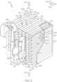
- FIG. 2 the central unit 206 of the heat exchanger system 200 is shown in greater detail according to example embodiments.
- a Cartesian coordinate system with a first axis 201, a second axis 203, and a third axis 205 orthogonally arranged is shown for purposes of reference.
- the first axis 201 indicates a normally vertical direction (e.g., directed along the force of gravity) whereas the second and third axes 203, 205 indicate normally horizontal directions.
- the central unit 206 may generally include an outer casing 208 and a core structure 214 that is received in the outer casing 208. A portion of the outer casing 208 is shown in phantom in FIG. 2 to more clearly show the core structure 214.
- the central unit 206 may also include one or more support brackets 233 that extend between the core structure 214 and the outer casing 208 and that support the core structure 214 therein.
- the outer casing 208 may be a hollow container with a plurality of relatively thin walls made of metal. In some embodiments, the outer casing 208 may be generally cuboid in shape; however, it will be appreciated that the outer casing 208 may have a variety of shapes (e.g., a rounded and cylindrical shape, etc.) without departing from the scope of the present disclosure.
- the outer casing 208 may include a first open end defining an air inlet 210 into the outer casing 208.
- the outer casing 208 may also include a second open end defining an air outlet 212 from the casing 208.
- the air inlet 210 and the air outlet 212 may be spaced apart at a distance along the first axis 201, on opposite ends of the outer casing 208.
- the air inlet 210 and/or the air outlet 212 may be rectangular and substantially aligned along the first axis 201.
- the air inlet 210 and/or the air outlet 212 may include a filtering element, such as a screen, a mesh, a porous filter, etc.
- the air inlet 210 may be fluidly connected to the inlet passage 202 ( FIG. 1 ), and the air outlet 212 may be fluidly connected to the outlet passage 204 ( FIG. 1 ). Accordingly, an airflow path 227 provided by the inlet passage 202 may be partly defined through the outer casing 208, from the air inlet 210 to the air outlet 212.
- the core structure 214 of the central unit 206 may be received within the outer casing 208.
- An outer profile 215 of the core structure 214 may resemble a three-dimensional shape, such as a cuboid shape, a cylindrical shape, or otherwise.
- the shape of the outer profile 215 may correspond to that of the outer casing 208.
- the outer profile 215 of the core structure 214 and the interior of the outer casing 208 may be cuboid in shape, but these components may be cylindrical in other embodiments of the present disclosure.
- the outer profile 215 of the core structure 214 is generally cuboid so as to define an upper side 207, a lower side 209, and four lateral sides 211a, 211b, 211c, 211d.
- the upper side 207 may face the air inlet 210
- the lower side 209 may face the air outlet 212.
- the upper and lower sides 207, 209 may be separated along the first axis 201, and the lateral sides 211a, 211b, 211c, 211d may extend along the first axis 201.
- the lateral sides 211a, 211b, 211c, 211d may oppose the side walls of the outer casing 208 and there may be space therebetween to define part of the airflow path 227.
- the core structure 2 includes an elongate flow structure 216.
- the elongate flow structure 216 may be a rigid tube, pipe, hose, line, or other conduit.
- the elongate flow structure 216 may be made out of a rigid thin-walled material that has high heat transfer properties (high heat transfer coefficient).
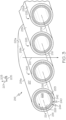
- the elongate flow structure 216 may have an outer surface 217 that is rounded (e.g., circular) in cross section as shown in FIG. 3 ; however, the outer surface 217 can have other shapes as will be discussed.
- the elongate flow structure 216 may include a first end 220 and a second end 222, and the flow structure 216 may extend continuously along a non-linear axis 218 between the ends 220, 222.
- the elongate flow structure 216 may be compacted within a three-dimensional space that corresponds to the cuboid outer profile 215 of the core structure 214. Portions of the axis 218 may be linear while other portions may turn, bend, and change directions. In some embodiments, the axis 218 may change directions repeatedly throughout the core structure 214.
- the elongate flow structure 216 may bend and turn inward upon itself in some embodiments.
- the elongate flow structure 216 may include relatively long and straight runs, such as a first run 219a, a second run 219b, a third run 219c, a fourth run 219d, and so on.
- the elongate flow structure 216 may also include a plurality of turns, such as first turn 221a, a second turn 221b, a third turn 221c, and so on.
- the runs 219a-d may extend substantially parallel to each other and/or substantially parallel to the second axis 203 so as to extend between the opposing lateral sides 211a, 211c of the core structure 214.
- the runs 219a-219d may lie substantially within a plane defined by the second and third axes 203, 205.
- the first turn 221a may be a one-hundred eighty degree turn that connects the first and second runs 219a, 219b proximate lateral side 211c as shown in FIGS. 2 and 3 .
- the radius of the first turn 221a may be relatively small such that the outer surface 217 of the first run 219a is directly adjacent, layered on, and/or connected to the second run 219b.
- the second turn 221b may be similar except that it may connect the second run 219b and the third run 219c proximate the lateral side 211a.
- the outer surfaces 217 of the second and third runs 219b, 219c may be directly adjacent, layered on each other, and/or connected.
- the third turn 221c may connect the third run 219c and the fourth run 219d, and so on continuously in this back-and-forth pattern until a fifth run 219e that is disposed proximate the lateral side 211b.
- the elongate flow structure 216 may be arranged in a first layer 223a.
- the layer 223a may lie substantially within the plane defined by the second and third axes 203, 205 and may define the upper side 207 of the core structure 214. As shown in FIG.
- the elongate flow structure 216 may also include a fifth turn 229 that is similar to the other turns 221a-c except that the fifth turn 229 curves within a (vertical) plane defined by the first axis and the second axis 203.
- the fifth turn 229 may connect the fifth run 219e and a sixth run 219f that is disposed directly underneath the fifth run 219e. From the sixth run 219f, the elongate flow structure 216 may extend back-and-forth in a second layer 223b toward the lateral side 211d, then a third layer 223c, and so on.
- the layers 223a-223c may be stacked (vertically) along the first axis 201, and in some embodiments, the runs and turns within the different layers 223a-223c may be substantially aligned along the first axis 201.
- the second end 222 of the elongate flow structure 216 may be included in a fourth layer 223d that substantially defines the lower side 209 of the core structure 214.
- the elongate flow structure 219 may also define one or more openings 225 through the core structure 214.
- the outer surfaces 217 between neighboring areas of the elongate flow structure 219 may be spaced apart to define openings 225 therebetween.
- the openings 225 may be fluidly connected between the different layers 223a-223d such that a continuous airflow path 227 is defined through the core structure 214.
- the airflow path 227 may extend generally along the first axis 201 from the upper side 207 to the lower side 209; however, there may be openings 225 in the core structure 214 that direct the airflow path 227 laterally (i.e., along the second and/or third axes 203, 205) through the core structure 214.
- the elongate flow structure 216 defines one or more internal flow paths, such as an oil flow path 224.
- the oil flow path 224 may be defined by an inner surface 226 of the elongate flow structure 216.
- the inner surface 226 may be rounded (e.g., circular) in cross section, and may be substantially centered about the axis 218 in some embodiments.
- This inner surface 226 may extend continuously along the axis 218 to define an oil passage 228 through the elongate flow structure 216, from the first end 220 to the second end 222.
- the oil passage 228 may include an inlet end 220 and an outlet end 232.
- the inlet end 220 may be disposed proximate the first end 220 of the elongate flow structure 216, and the outlet end 232 may be disposed proximate the second end 222.
- the core structure 214 may also include an oil input line 234 and an oil output line 236.
- the input line 234 may be a pipe or tube that extends into and merges with the first end 220 of the elongate flow structure 216, and an internal passage of the input line 234 may be fluidly connected to the inlet end 220 of the oil passage 228.
- the output line 236 may be similar, but the internal passage of the output line 236 may be fluidly connected to the outlet end 222 of the oil passage 228.
- the input line 234 and output line 236 may fluidly connect the oil passage 228 to the oil circulation system 150 ( FIG. 1 ) such that the input line 234 supplies oil to the oil passage 228, and the output line 236 receives oil from the oil passage 228.
- the elongate flow structure 219 includes a fuel flow path 240.
- the fuel flow path 240 may be defined by an inner surface 242 of the elongate flow structure 219.
- the inner surface 242 may extend continuously along the axis 218 to define a fuel passage 244 through the elongate flow structure 216, from the second end 222 to the first end 220.
- the fuel passage 244 may include an inlet end 246 and an outlet end 248.
- the inlet end 246 may be disposed proximate the second end 222 of the elongate flow structure 216, and the outlet end 248 may be disposed proximate the first end 220.
- the fuel passage 244 may be C-shaped in cross section and may extend about the axis 218 and about the oil passage 228.
- the fuel flow path 240 at least partly surrounds or encompasses a majority of the oil flow path 224 in the cross section.
- the fuel flow path 240 may be disposed between the oil flow path 224 and the outer surface 217 in a radial direction relative to the axis 218.
- the fuel flow path 240 may be arranged as a jacket (a cooling jacket) for the oil flow path 224.
- the cross-sectional area of the fuel passage 244 may be considerably smaller than that of the oil passage 228.
- the fuel flow path 240 and/or the oil flow path 224 may be included differently without departing from the scope of the present disclosure.
- at least one of the paths 240, 224 may be wedge-shaped in cross section.
- the fuel flow path 240 may be connected to and may receive fuel via the fuel input line 250 ( FIGS. 1 and 2 ).
- the input line 250 may include a pipe or tube that extends into and merges with the second end 222 of the elongate flow structure 216 and that supplies fuel to the fuel passage 244.
- the fuel flow path 240 may also be connected to and may output fuel via the fuel output line 252.
- the output line 252 may extend from and branch from the first end 220 of the elongate flow structure 216.
- the oil flow path 224 and the fuel flow path 240 are arranged in a heat exchanging arrangement within the elongate flow structure 216.
- the fuel flow path 240 may surround a majority of the oil flow path 224 and share a common internal wall 253 of the elongate flow structure 216. Accordingly heat transfers generally radially outward from the oil in the oil flow path 224, through the thickness of the internal wall 253, and into the fuel of the fuel flow path 240.
- the elongate flow structure 216 may include an outer wall 299 disposed radially between the fuel flow path 240 and the outer surface 217. The outer wall 299 may provide another heat transfer medium, in that heat may transfer generally radially outward from the fuel in the fuel flow path 240, through the outer wall 299, and to the air flowing along the airflow path 227.
- the heat exchanger system 200 additionally includes a control system 260.
- the control system 260 may be a computerized device with a processor 262 with one or more modules that can be used to control operations of the system 200.
- the term module refers to any hardware, software, firmware, electronic control component, processing logic, and/or processor device, individually or in any combination, including without limitation: application specific integrated circuit (ASIC), an electronic circuit, a processor (shared, dedicated, or group) and memory that executes one or more software or firmware programs, a combinational logic circuit, and/or other suitable components that provide the described functionality.
- ASIC application specific integrated circuit
- the control system 260 includes and/or is communication with one or more sensors 264.
- the sensors 264 are configured to detect a characteristic of the oil in the oil flow path 224 and/or a characteristic of the fuel in the fuel flow path 240
- the sensor 264 include a temperature sensor configured to measure the temperature of the oil in the oil flow path 224 and/or the temperature of the fuel in the fuel flow path 240.
- the sensors 264 transmit corresponding signals to the processor 262, and the processor 262 controls an actuator 259 of the valve member 258 based on the detected oil and/or fuel temperatures.
- the processor 262 may rely on look-up tables stored in a memory element that correlate the current oil/fuel temperatures to a position setting for the valve member 258.
- the control system 260 may selectively change and adjust the mass flow rate of the air flowing along the airflow path 227 based on the conditions detected by the sensors 264.
- oil may flow, for example, from the accessory drive 115 to the heat exchanger system 200.
- This oil may flow into the core structure 214 via the input line 234.
- the oil may flow into the inlet end 230 of the oil flow path 224 of the elongate flow structure 216 and flow therethrough along the axis 218 toward the outlet end 232.
- the oil may also flow out of the core structure 214 via the output line 236, back to the accessory drive 115 to further lubricate the moving parts therein.
- fuel may enter the inlet end 246 of the fuel flow path 240 via the input line 250.
- the fuel may flow along the fuel flow path 240 along the axis 218 toward the outlet end 248.
- the fuel may flow out of the core structure 214 via the output line 252 toward the injector of the combustor 109 for fueling ignition within the combustion section 104.
- heat may transfer from the oil flow to the fuel flow, thereby cooling the oil.
- the oil may be maintained at a proper temperature, viscosity, etc. for providing suitable lubrication for the engine 100.
- This heat exchange effect may be supplemented by the air flowing along the airflow path 227.
- the air may flow around and through the core structure 214, thereby receiving heat from the fuel and/or oil flowing within the elongate flow structure 216.
- the airflow of the airflow path 227 may be used and controlled to supplement the heat exchange effect.
- the control system 260 may maintain the valve member 258 in a closed or partially closed position. This may be the normal or neutral position of the valve member 258, and the valve member 258 may be biased toward this position.
- the airflow may be provided to the core structure 214 at a relatively low mass flow rate. Accordingly, the heat exchanger system 200 may provide high efficiency using the fuel flow primarily to cool the oil.
- control system 260 may output a control signal to the actuator 259 for actuating the valve member 258 to an open or partially opened position.
- the airflow may be provided to the core structure 214 at a relatively high mass flow rate, thereby increasing the cooling effect and removing heat from the system.
- the control system 260 continuously monitors the fuel/oil temperatures and continuously adjusts the position of the valve member 258 accordingly. the control system 260 adjusts the airflow provided to the core structure 214 in an effort to maintain the temperatures of the oil and/or fuel below the threshold. Because the cooling effect may be selectively supplemented by the air in the airflow path 227, the size of the core structure 214 and, thus, the size of the overall heat exchanger system 200 may be reduced.
- the core structure 314 is illustrated according to additional embodiments of the present disclosure.
- the core structure 314 may be substantially similar to the embodiments of FIGS. 2-3 except as noted. Components that correspond to those of the embodiments of FIGS. 2 and 3 are indicated with corresponding reference numbers increased by 100.
- the outer surface 317 of the elongate flow structure 316 may include at least one flat side.
- the outer surface 317 may be polygonal (e.g., rectangular) in cross section.
- the oil flow path 324 may include at least one flat side in cross section.
- the oil flow path 324 may be polygonal (e.g., rectangular) in cross section.
- the elongate flow structure 316 may include a plurality of turbulators 380.
- the turbulators 380 may be bumps, posts, rails, fins, or other projections that project from the inner surface 326 into the oil flow path 324.
- the turbulators 380 may be configured to divert the oil flow, creating turbulence and promoting mixing. As such, the turbulators 380 may increase the heat transfer effect to the fuel flow path 340.
- the fuel flow path 340 may also be polygonal.
- the fuel flow path 340 may L-shaped.
- the fuel flow path 340 may partly surround the fuel flow path 340 in the cross section of FIG. 5 .
- the fuel flow path 340 may extend along two sides of the oil flow path 324.
- the core structure 314 may also include one or more flow straightener members 382.
- the flow straightener members 382 may be flat, smooth, and thin walls that extend along the axis 318 within the oil flow path 324. As shown in the illustrated embodiment, there may be three flow separators 382 that are received within the oil flow path 324. The flow separators 382 may separate, divide, and straighten the flow of oil into three separate channels extending along the axis 318.
- the heat exchanger system of the present disclosure may be manufactured in various ways without departing from the scope of the present disclosure.
- the elongate flow structure 216, 316 and/or other portions of the core structure 214, 314 may be constructed using rapid manufacturing techniques, such as additive manufacturing (e.g., 3-D printing).
- additive manufacturing e.g., 3-D printing
- the elongate flow structure 216, 316 may be formed as a unitary (one-piece) part, layer-by-layer until completed.
- the complex shapes, highly contoured surfaces, etc. may be formed with a high degree of precision and efficiency.
- the sensors 264 and any associated wiring may be embedded or otherwise attached to the core structure 214, 314 during the additive manufacturing process.
- at least part of the elongate flow structure 216, 316 may be extruded.
- the elongate flow structure 216, 316 may be assembled from a plurality of parts in some embodiments.
Landscapes
- Engineering & Computer Science (AREA)
- Physics & Mathematics (AREA)
- Mechanical Engineering (AREA)
- General Engineering & Computer Science (AREA)
- Thermal Sciences (AREA)
- Chemical & Material Sciences (AREA)
- Combustion & Propulsion (AREA)
- Geometry (AREA)
- Heat-Exchange Devices With Radiators And Conduit Assemblies (AREA)
Description
- The present disclosure generally relates to a heat exchanger and, more particularly, to a three-way heat exchanger for an auxiliary power unit.
- A heat exchanger may be provided for transferring heat from one fluid to another and for ultimately removing the heat from a system. For example, in the case of an engine, oil may flow through an engine component, then through a first flow path in a heat exchanger, and then back to the engine component. A second, comparatively cooler fluid may also flow through the heat exchanger, removing heat from the first fluid in so doing.
- However, conventional heat exchangers may be relatively bulky, heavy, difficult to manufacture, and costly. Accordingly, there is a need for an improved heat exchanger that provides high operating efficiency, that is relatively compact, and that provides manufacturing improvements. Furthermore, other desirable features and characteristics of the present disclosure will become apparent from the subsequent detailed description and the appended claims, taken in conjunction with the accompanying drawings and this background section.
- Document
JP2001280864 - Aspects and preferred embodiments of the invention are defined in the appended claims.
- In an embodiment, there is provided a heat exchanger system according to Claim 1.
- In another embodiment, there is provided a method of operating a heat exchanger system in accordance with Claim 12.
- Furthermore, other desirable features and characteristics of the gas turbine engine will become apparent from the above background, the subsequent detailed description, and the appended claims, taken in conjunction with the accompanying drawings.
- The present disclosure will hereinafter be described in conjunction with the following drawing figures, wherein like numerals denote like elements, and wherein:
-
FIG. 1 is a schematic view of a gas turbine engine with a heat exchanger system according to example embodiments of the present disclosure; -
FIG. 2 is a perspective view of a heat exchanger system of the gas turbine engine ofFIG. 1 ; -
FIG. 3 is a perspective section of a portion of the heat exchanger ofFIG. 2 ; -
FIG. 4 is a perspective view of the heat exchanger system according to additional embodiments of the present disclosure; -
FIG. 5 is a perspective section view of the heat exchanger system ofFIG. 4 ; and -
FIG. 6 is a perspective section view of the heat exchanger system ofFIG. 4 . - The following detailed description is merely exemplary in nature and is not intended to limit the present disclosure or the application and uses of the present disclosure. Furthermore, there is no intention to be bound by any theory presented in the preceding background or the following detailed description.
- The present disclosure provides a heat exchanger system with a three-way heat exchanger configured to receive at least three different fluid flows (e.g., an oil flow, a fuel flow, and an airflow). The heat exchanger is constructed such that heat transfers from one fluid flow to at least one other fluid flow. Also, the heat exchanger may have different modes, different settings, different controls, and/or a plurality of operational configurations. The operations of the heat exchanger may selectively change based upon current operating conditions.
- The heat exchanger system receives a flow of a first fluid from another component of a gas turbine engine. For example, the heat exchanger receives an oil flow (e.g., a flow of hot lubrication oil) from a component of an auxiliary power unit. The heat exchanger also receives a fuel flow that is used to cool the first fluid. Moreover, the heat exchanger receives an airflow. The airflow through the heat exchanger system may be selectively adjusted, for example, using a valve member. The adjustments are selectively controlled by a control system, such as a computerized control system. The control system adjusts the airflow based upon one or more variable characteristics of the first fluid flow and/or the fuel flow.
- The heat exchanger includes a core structure defined by an elongate flow structure (e.g., a pipe, tube, hose, conduit, etc.). The elongate flow structure may extend in various directions along an axis. The elongate flow structure may be arranged to define an outer profile of the core structure as well as one or more openings through the core structure. The opening(s) define a flow path for the airflow through the core structure. Also, the elongate flow structure internally defines an oil flow path as well as fuel flow path. The oil and fuel flow paths may extend along the axis of the elongate flow structure (i.e., along a so-called "tortuous path") and may be coupled for heat exchange such that the fuel cools the oil as the fluids flow through the core structure. This liquid-to-liquid heat exchange allows the heat exchanger to operate at high efficiency. Furthermore, the airflow over the core structure may provide further cooling effect, for example, by cooling the fuel flow and/or the oil flow. In some embodiments, the airflow may be selectively provided to supplement the cooling effect as needed. For example, if the oil and/or fuel temperature is low, the control system may adjust the airflow to a lower flow rate (or to a zero or negligible flow rate) through the core structure. Conversely, if the oil/fuel temperature exceeds a temperature threshold, then the control system may automatically increase the flow rate of the air, thereby increasing the cooling effect.
- Accordingly, the heat exchanger may provide high operating efficiencies across a broad range of operating conditions. The heat exchanger may also be relatively compact and lightweight. Furthermore, the heat exchanger may provide various manufacturing efficiencies.
- Embodiments of the present disclosure may be described herein in terms of functional and/or logical block components and various processing steps. It should be appreciated that such block components may be realized by any number of hardware, software, and/or firmware components configured to perform the specified functions. For example, an embodiment of the present disclosure may employ various integrated circuit components, e.g., memory elements, digital signal processing elements, logic elements, look-up tables, or the like, which may carry out a variety of functions under the control of one or more microprocessors or other control devices. In addition, those skilled in the art will appreciate that embodiments of the present disclosure may be practiced in conjunction with any number of systems, and that the heat exchanger system described herein is merely one exemplary embodiment of the present disclosure.
- For the sake of brevity, conventional techniques related to signal processing, data transmission, signaling, control, and other functional aspects of the systems (and the individual operating components of the systems) may not be described in detail herein. Furthermore, the connecting lines shown in the various figures contained herein are intended to represent example functional relationships and/or physical couplings between the various elements. It should be noted that many alternative or additional functional relationships or physical connections may be present in an embodiment of the present disclosure.
- Turning now to
FIG. 1 , a schematic diagram of aheat exchanger system 200 is shown integrated into another system, such as agas turbine engine 100. Theengine 100 may be included on avehicle 110 of any suitable type, such as an aircraft, rotorcraft, marine vessel, train, or other vehicle, and theengine 100 can provide auxiliary power to thevehicle 110. - It will be appreciated that the
heat exchanger system 200 may be used with another machine (other than a gas turbine engine 100) without departing from the scope of the present disclosure. Furthermore, theheat exchanger system 200 may be integrated within and connected to thegas turbine engine 100 in a variety of ways, examples of which will be discussed in detail below. Moreover, theheat exchanger system 200 may be referred to as a "three-way heat exchanger system" in that it receives at least three different fluids, and heat is exchanged between at least two of the fluids. It will be appreciated that the term "three-way heat exchanger system" is used broadly herein and will be interpreted to include heat exchangers that receive three or more different fluids and that provide heat exchange between at least two of those fluids during use. - In some embodiments, the
gas turbine engine 100 may comprise an auxiliary power unit (APU) for an aircraft. Theheat exchanger system 200 may be useful in an APU because, typically, the fuel consumption requirements of the APU and fuel flow rate are low (e.g., compared to a main engine). However, these characteristics allow the fuel flow to be directed through theheat exchanger system 200 for cooling another fluid in a highly efficient manner. For example, the fuel may be used to cool an oil that lubricates a component of theengine 100. - The
engine 100 may generally include anintake section 101, acompressor section 102, acombustion section 104, aturbine section 106, and anexhaust section 108. At least some of these sections may be cooperatively defined by arotor 103 and anouter structure 105. Therotor 103 may be supported for rotation within theouter structure 105 by one or more bearings. Theouter structure 105 may include one or more housing members, support structures, and shroud members which oppose components of therotor 103 and define an outer radial boundary for fluids moving through theengine 100. - The
intake section 101 may receive an intake airstream indicated byarrows 107 inFIG. 1 . Therotor 103 may include acompressor wheel 117 disposed within thecompressor section 102. Thecompressor wheel 117 may rotate relative to theouter structure 105 to compress theairstream 107, which is passed to thecombustion section 104. Fuel is provided to at least onecombustor 109 for igniting an air-fuel mixture within thecombustion section 104. The energy from combustion drives aturbine wheel 111 of therotor 103 within theturbine section 106, and exhaust flows out of theengine 100 via theexhaust section 108. - Rotation of the
turbine wheel 111 drives ashaft 112 of the rotor 113, which may provide mechanical power to agenerator 114 via anaccessory drive 115. Thegenerator 114 may convert this mechanical power (i.e., power from a rotating input shaft) into electrical energy that is provided to one or more electrical systems of thevehicle 110. Also, in some embodiments, the accessory drive 115 (e.g., one or more gear trains) may transfer mechanical power from therotating shaft 112 to another gas turbine engine of thevehicle 110 for starting the other engine. - The
heat exchanger system 200 may include aducting arrangement 160. Theducting arrangement 160 may include aninlet passage 202 and anoutlet passage 204. Theheat exchanger system 200 may further include acentral unit 206 that is disposed between theinlet passage 202 and theoutlet passage 204. Theducting arrangement 160 may direct an airflow through thecentral unit 206. As represented inFIG. 1 , air from theheat exchanger system 200 may outlet to join theairstream 107 within theintake section 101 of thegas turbine engine 100; however, in other embodiments, air from theheat exchanger system 200 may outlet to another location. - The
central unit 206 may also be in fluid communication with one or more components of thegas turbine engine 100 via anoil circulation system 150. As shown inFIG. 1 , theoil circulation system 150 may fluidly connect theaccessory drive 115 and thecentral unit 206 of theheat exchanger system 200; however, theoil circulation system 150 may fluidly connect thecentral unit 206 with another lubricated component, such as a bearing of theshaft 112, or another component of thegas turbine engine 100. - Furthermore, the
central unit 206 may receive a flow of fuel (e.g., from a tank, fuel pump, or other fuel source) via afuel input line 250. Afuel output line 252 may extend from thecentral unit 206 to thecombustor 109 of thegas turbine engine 100. As will be discussed, the fuel flow through thecentral unit 206 may receive heat from (i.e., cool) the oil provided via theoil circulation system 150, and the fuel flow may transfer the heat away from thecentral unit 206. - Air may flow through the
central unit 206 via theducting arrangement 160 to further increase the cooling effect. Specifically, the airflow may receive heat from the flow of oil and/or fuel for supplementing the cooling effect of theheat exchanger system 200. Ultimately, the oil flowing through thecentral unit 206 may be transferred to and cooled by the fuel and/or air flowing through thecentral unit 206. - Moreover, the
ducting arrangement 160 may include avalve member 258. Thevalve member 258 may be provided upstream of thecentral unit 206 in some embodiments. In some embodiments, thevalve member 258 may be a door or panel on the exterior of theaircraft 110, and thevalve member 258 may actuate to open and close the door/panel. Thevalve member 258 may be selectively and automatically actuated by anactuator 259, such as an electric motor or hydraulic actuator. Accordingly, the airflow (e.g., the mass flow rate of the airflow) moving through thecentral unit 206 may be selectively altered. For example, the airflow may be cut off (i.e., zero mass flow rate) when thevalve member 258 is closed, and the airflow may be provided (i.e., a positive mass flow rate) when thevalve member 258 is open. Also, thevalve member 258 andactuator 259 may be configured such that thevalve member 258 may be actuated and retained in a variety of different positions, where the airflow rate to theheat exchanger system 200 is different in each position. As will be discussed, the airflow may be selectively changed to supplement the cooling effect provided by the fuel flow. In additional embodiments, theducting arrangement 160 may include a fan instead of (or in addition to) thevalve member 258. The speed of the fan may be selectively changed (e.g., between an off position, a low speed, and a high speed) to change the airflow through thecentral unit 206. - Referring now to
FIG. 2 , thecentral unit 206 of theheat exchanger system 200 is shown in greater detail according to example embodiments. A Cartesian coordinate system with afirst axis 201, asecond axis 203, and athird axis 205 orthogonally arranged is shown for purposes of reference. In some embodiments, thefirst axis 201 indicates a normally vertical direction (e.g., directed along the force of gravity) whereas the second andthird axes - The
central unit 206 may generally include anouter casing 208 and a core structure 214 that is received in theouter casing 208. A portion of theouter casing 208 is shown in phantom inFIG. 2 to more clearly show the core structure 214. Thecentral unit 206 may also include one ormore support brackets 233 that extend between the core structure 214 and theouter casing 208 and that support the core structure 214 therein. - In some embodiments, the
outer casing 208 may be a hollow container with a plurality of relatively thin walls made of metal. In some embodiments, theouter casing 208 may be generally cuboid in shape; however, it will be appreciated that theouter casing 208 may have a variety of shapes (e.g., a rounded and cylindrical shape, etc.) without departing from the scope of the present disclosure. Theouter casing 208 may include a first open end defining anair inlet 210 into theouter casing 208. Theouter casing 208 may also include a second open end defining anair outlet 212 from thecasing 208. In some embodiments, theair inlet 210 and theair outlet 212 may be spaced apart at a distance along thefirst axis 201, on opposite ends of theouter casing 208. Theair inlet 210 and/or theair outlet 212 may be rectangular and substantially aligned along thefirst axis 201. Furthermore, in some embodiments, theair inlet 210 and/or theair outlet 212 may include a filtering element, such as a screen, a mesh, a porous filter, etc. Theair inlet 210 may be fluidly connected to the inlet passage 202 (FIG. 1 ), and theair outlet 212 may be fluidly connected to the outlet passage 204 (FIG. 1 ). Accordingly, anairflow path 227 provided by theinlet passage 202 may be partly defined through theouter casing 208, from theair inlet 210 to theair outlet 212. - As stated, the core structure 214 of the
central unit 206 may be received within theouter casing 208. Anouter profile 215 of the core structure 214 may resemble a three-dimensional shape, such as a cuboid shape, a cylindrical shape, or otherwise. The shape of theouter profile 215 may correspond to that of theouter casing 208. For example, theouter profile 215 of the core structure 214 and the interior of theouter casing 208 may be cuboid in shape, but these components may be cylindrical in other embodiments of the present disclosure. - In the illustrated embodiment, for example, the
outer profile 215 of the core structure 214 is generally cuboid so as to define anupper side 207, alower side 209, and fourlateral sides upper side 207 may face theair inlet 210, and thelower side 209 may face theair outlet 212. Thus, the upper andlower sides first axis 201, and thelateral sides first axis 201. Thelateral sides outer casing 208 and there may be space therebetween to define part of theairflow path 227. There may also be one ormore openings 225 through the core structure 214 as will be discussed below, and theopenings 225 may define another part of theairflow path 227 of theheat exchanger system 200. - The core structure 2 includes an
elongate flow structure 216. Theelongate flow structure 216 may be a rigid tube, pipe, hose, line, or other conduit. Theelongate flow structure 216 may be made out of a rigid thin-walled material that has high heat transfer properties (high heat transfer coefficient). In some embodiments, theelongate flow structure 216 may have anouter surface 217 that is rounded (e.g., circular) in cross section as shown inFIG. 3 ; however, theouter surface 217 can have other shapes as will be discussed. - The
elongate flow structure 216 may include a first end 220 and asecond end 222, and theflow structure 216 may extend continuously along anon-linear axis 218 between theends 220, 222. Generally, theelongate flow structure 216 may be compacted within a three-dimensional space that corresponds to the cuboidouter profile 215 of the core structure 214. Portions of theaxis 218 may be linear while other portions may turn, bend, and change directions. In some embodiments, theaxis 218 may change directions repeatedly throughout the core structure 214. Theelongate flow structure 216 may bend and turn inward upon itself in some embodiments. - For example, as shown in
FIG. 2 , theelongate flow structure 216 may include relatively long and straight runs, such as afirst run 219a, asecond run 219b, athird run 219c, afourth run 219d, and so on. Theelongate flow structure 216 may also include a plurality of turns, such asfirst turn 221a, asecond turn 221b, athird turn 221c, and so on. In some embodiments, theruns 219a-d may extend substantially parallel to each other and/or substantially parallel to thesecond axis 203 so as to extend between the opposinglateral sides runs 219a-219d may lie substantially within a plane defined by the second andthird axes first turn 221a may be a one-hundred eighty degree turn that connects the first andsecond runs lateral side 211c as shown inFIGS. 2 and3 . The radius of thefirst turn 221a may be relatively small such that theouter surface 217 of thefirst run 219a is directly adjacent, layered on, and/or connected to thesecond run 219b. Thesecond turn 221b may be similar except that it may connect thesecond run 219b and thethird run 219c proximate thelateral side 211a. Theouter surfaces 217 of the second andthird runs third turn 221c may connect thethird run 219c and thefourth run 219d, and so on continuously in this back-and-forth pattern until afifth run 219e that is disposed proximate thelateral side 211b. Accordingly, theelongate flow structure 216 may be arranged in afirst layer 223a. Thelayer 223a may lie substantially within the plane defined by the second andthird axes upper side 207 of the core structure 214. As shown inFIG. 2 , theelongate flow structure 216 may also include afifth turn 229 that is similar to theother turns 221a-c except that thefifth turn 229 curves within a (vertical) plane defined by the first axis and thesecond axis 203. Thefifth turn 229 may connect thefifth run 219e and asixth run 219f that is disposed directly underneath thefifth run 219e. From thesixth run 219f, theelongate flow structure 216 may extend back-and-forth in asecond layer 223b toward thelateral side 211d, then athird layer 223c, and so on. Thelayers 223a-223c may be stacked (vertically) along thefirst axis 201, and in some embodiments, the runs and turns within thedifferent layers 223a-223c may be substantially aligned along thefirst axis 201. Thesecond end 222 of theelongate flow structure 216 may be included in afourth layer 223d that substantially defines thelower side 209 of the core structure 214. - As shown in
FIG. 3 , the elongate flow structure 219 may also define one ormore openings 225 through the core structure 214. For example, theouter surfaces 217 between neighboring areas of the elongate flow structure 219 may be spaced apart to defineopenings 225 therebetween. Theopenings 225 may be fluidly connected between thedifferent layers 223a-223d such that acontinuous airflow path 227 is defined through the core structure 214. Theairflow path 227 may extend generally along thefirst axis 201 from theupper side 207 to thelower side 209; however, there may beopenings 225 in the core structure 214 that direct theairflow path 227 laterally (i.e., along the second and/orthird axes 203, 205) through the core structure 214. - Moreover, as shown in
FIG. 3 , theelongate flow structure 216 defines one or more internal flow paths, such as anoil flow path 224. Theoil flow path 224 may be defined by aninner surface 226 of theelongate flow structure 216. Theinner surface 226 may be rounded (e.g., circular) in cross section, and may be substantially centered about theaxis 218 in some embodiments. Thisinner surface 226 may extend continuously along theaxis 218 to define anoil passage 228 through theelongate flow structure 216, from the first end 220 to thesecond end 222. Specifically, as shown inFIG. 2 , theoil passage 228 may include an inlet end 220 and anoutlet end 232. The inlet end 220 may be disposed proximate the first end 220 of theelongate flow structure 216, and theoutlet end 232 may be disposed proximate thesecond end 222. - As shown in
FIG. 2 , the core structure 214 may also include anoil input line 234 and an oil output line 236. Theinput line 234 may be a pipe or tube that extends into and merges with the first end 220 of theelongate flow structure 216, and an internal passage of theinput line 234 may be fluidly connected to the inlet end 220 of theoil passage 228. The output line 236 may be similar, but the internal passage of the output line 236 may be fluidly connected to theoutlet end 222 of theoil passage 228. Furthermore, theinput line 234 and output line 236 may fluidly connect theoil passage 228 to the oil circulation system 150 (FIG. 1 ) such that theinput line 234 supplies oil to theoil passage 228, and the output line 236 receives oil from theoil passage 228. - Additionally, as shown in
FIG. 3 , the elongate flow structure 219 includes afuel flow path 240. Thefuel flow path 240 may be defined by aninner surface 242 of the elongate flow structure 219. Theinner surface 242 may extend continuously along theaxis 218 to define afuel passage 244 through theelongate flow structure 216, from thesecond end 222 to the first end 220. Specifically, as shown inFIG. 2 , thefuel passage 244 may include aninlet end 246 and anoutlet end 248. Theinlet end 246 may be disposed proximate thesecond end 222 of theelongate flow structure 216, and theoutlet end 248 may be disposed proximate the first end 220. - As shown in
FIG. 3 , thefuel passage 244 may be C-shaped in cross section and may extend about theaxis 218 and about theoil passage 228. In other words, thefuel flow path 240 at least partly surrounds or encompasses a majority of theoil flow path 224 in the cross section. Thus, as shown in the cross section ofFIG. 3 , thefuel flow path 240 may be disposed between theoil flow path 224 and theouter surface 217 in a radial direction relative to theaxis 218. In the illustrated embodiment, for example, thefuel flow path 240 may be arranged as a jacket (a cooling jacket) for theoil flow path 224. The cross-sectional area of thefuel passage 244 may be considerably smaller than that of theoil passage 228. - However, it will be appreciated that the
fuel flow path 240 and/or theoil flow path 224 may be included differently without departing from the scope of the present disclosure. For example, at least one of thepaths multiple paths elongate flow structure 216. - The
fuel flow path 240 may be connected to and may receive fuel via the fuel input line 250 (FIGS. 1 and2 ). As shown inFIG. 2 , theinput line 250 may include a pipe or tube that extends into and merges with thesecond end 222 of theelongate flow structure 216 and that supplies fuel to thefuel passage 244. Thefuel flow path 240 may also be connected to and may output fuel via thefuel output line 252. As shown inFIG. 2 , theoutput line 252 may extend from and branch from the first end 220 of theelongate flow structure 216. - The
oil flow path 224 and thefuel flow path 240 are arranged in a heat exchanging arrangement within theelongate flow structure 216. For example, thefuel flow path 240 may surround a majority of theoil flow path 224 and share a commoninternal wall 253 of theelongate flow structure 216. Accordingly heat transfers generally radially outward from the oil in theoil flow path 224, through the thickness of theinternal wall 253, and into the fuel of thefuel flow path 240. Moreover, theelongate flow structure 216 may include an outer wall 299 disposed radially between thefuel flow path 240 and theouter surface 217. The outer wall 299 may provide another heat transfer medium, in that heat may transfer generally radially outward from the fuel in thefuel flow path 240, through the outer wall 299, and to the air flowing along theairflow path 227. - The
heat exchanger system 200 additionally includes acontrol system 260. In some embodiments, thecontrol system 260 may be a computerized device with aprocessor 262 with one or more modules that can be used to control operations of thesystem 200. As used herein, the term module refers to any hardware, software, firmware, electronic control component, processing logic, and/or processor device, individually or in any combination, including without limitation: application specific integrated circuit (ASIC), an electronic circuit, a processor (shared, dedicated, or group) and memory that executes one or more software or firmware programs, a combinational logic circuit, and/or other suitable components that provide the described functionality. - The
control system 260 includes and/or is communication with one ormore sensors 264. Thesensors 264 are configured to detect a characteristic of the oil in theoil flow path 224 and/or a characteristic of the fuel in thefuel flow path 240 Thesensor 264 include a temperature sensor configured to measure the temperature of the oil in theoil flow path 224 and/or the temperature of the fuel in thefuel flow path 240. Thesensors 264 transmit corresponding signals to theprocessor 262, and theprocessor 262 controls anactuator 259 of thevalve member 258 based on the detected oil and/or fuel temperatures. In some embodiments, theprocessor 262 may rely on look-up tables stored in a memory element that correlate the current oil/fuel temperatures to a position setting for thevalve member 258. Thus, thecontrol system 260 may selectively change and adjust the mass flow rate of the air flowing along theairflow path 227 based on the conditions detected by thesensors 264. - Accordingly, during operations of the
gas turbine engine 100, oil may flow, for example, from theaccessory drive 115 to theheat exchanger system 200. This oil may flow into the core structure 214 via theinput line 234. The oil may flow into theinlet end 230 of theoil flow path 224 of theelongate flow structure 216 and flow therethrough along theaxis 218 toward theoutlet end 232. The oil may also flow out of the core structure 214 via the output line 236, back to theaccessory drive 115 to further lubricate the moving parts therein. Meanwhile, fuel may enter theinlet end 246 of thefuel flow path 240 via theinput line 250. The fuel may flow along thefuel flow path 240 along theaxis 218 toward theoutlet end 248. The fuel may flow out of the core structure 214 via theoutput line 252 toward the injector of thecombustor 109 for fueling ignition within thecombustion section 104. Within the core structure 214, heat may transfer from the oil flow to the fuel flow, thereby cooling the oil. Thus, the oil may be maintained at a proper temperature, viscosity, etc. for providing suitable lubrication for theengine 100. - This heat exchange effect may be supplemented by the air flowing along the
airflow path 227. For example, the air may flow around and through the core structure 214, thereby receiving heat from the fuel and/or oil flowing within theelongate flow structure 216. The airflow of theairflow path 227 may be used and controlled to supplement the heat exchange effect. - For example, in situations in which the
sensors 264 detect that the oil/fuel temperature is below a predetermined threshold, thecontrol system 260 may maintain thevalve member 258 in a closed or partially closed position. This may be the normal or neutral position of thevalve member 258, and thevalve member 258 may be biased toward this position. Thus, the airflow may be provided to the core structure 214 at a relatively low mass flow rate. Accordingly, theheat exchanger system 200 may provide high efficiency using the fuel flow primarily to cool the oil. - However, in situations in which the
sensors 264 detect that the oil/fuel temperature exceeds the threshold, thecontrol system 260 may output a control signal to theactuator 259 for actuating thevalve member 258 to an open or partially opened position. Thus, the airflow may be provided to the core structure 214 at a relatively high mass flow rate, thereby increasing the cooling effect and removing heat from the system. - The
control system 260 continuously monitors the fuel/oil temperatures and continuously adjusts the position of thevalve member 258 accordingly. thecontrol system 260 adjusts the airflow provided to the core structure 214 in an effort to maintain the temperatures of the oil and/or fuel below the threshold. Because the cooling effect may be selectively supplemented by the air in theairflow path 227, the size of the core structure 214 and, thus, the size of the overallheat exchanger system 200 may be reduced. - Referring now to
FIGS. 4 ,5 , and6 , thecore structure 314 is illustrated according to additional embodiments of the present disclosure. Thecore structure 314 may be substantially similar to the embodiments ofFIGS. 2-3 except as noted. Components that correspond to those of the embodiments ofFIGS. 2 and3 are indicated with corresponding reference numbers increased by 100. - As shown in
FIG. 5 , theouter surface 317 of theelongate flow structure 316 may include at least one flat side. For example, theouter surface 317 may be polygonal (e.g., rectangular) in cross section. Likewise, theoil flow path 324 may include at least one flat side in cross section. Theoil flow path 324 may be polygonal (e.g., rectangular) in cross section. - Also, as shown in
FIG. 5 , theelongate flow structure 316 may include a plurality ofturbulators 380. Theturbulators 380 may be bumps, posts, rails, fins, or other projections that project from theinner surface 326 into theoil flow path 324. Theturbulators 380 may be configured to divert the oil flow, creating turbulence and promoting mixing. As such, theturbulators 380 may increase the heat transfer effect to thefuel flow path 340. Thefuel flow path 340 may also be polygonal. For example, thefuel flow path 340 may L-shaped. Thefuel flow path 340 may partly surround thefuel flow path 340 in the cross section ofFIG. 5 . Thefuel flow path 340 may extend along two sides of theoil flow path 324. - Furthermore, as shown in
FIG. 6 , thecore structure 314 may also include one or moreflow straightener members 382. Theflow straightener members 382 may be flat, smooth, and thin walls that extend along theaxis 318 within theoil flow path 324. As shown in the illustrated embodiment, there may be threeflow separators 382 that are received within theoil flow path 324. Theflow separators 382 may separate, divide, and straighten the flow of oil into three separate channels extending along theaxis 318. - The heat exchanger system of the present disclosure may be manufactured in various ways without departing from the scope of the present disclosure. For example, the
elongate flow structure core structure 214, 314 may be constructed using rapid manufacturing techniques, such as additive manufacturing (e.g., 3-D printing). Thus, in some embodiments, theelongate flow structure sensors 264 and any associated wiring may be embedded or otherwise attached to thecore structure 214, 314 during the additive manufacturing process. In other embodiments, at least part of theelongate flow structure elongate flow structure - While at least one exemplary embodiment has been presented in the foregoing detailed description, it should be appreciated that a vast number of variations exist. It should also be appreciated that the exemplary embodiment or exemplary embodiments are only examples, and are not intended to limit the scope, applicability, or configuration of the present disclosure in any way. Rather, the foregoing detailed description will provide those skilled in the art with a convenient road map for implementing an exemplary embodiment of the present disclosure. It is understood that various changes may be made in the function and arrangement of elements described in an exemplary embodiment without departing from the scope of the present disclosure as set forth in the appended claims.
Claims (12)
- A heat exchanger system (200) comprising:a core structure (214, 314) at least partly defined by an elongate flow structure (216, 316), the elongate flow structure (216, 316) extending along an axis (218, 318) from a first end (220) to a second end (222), wherein the elongate flow structure (216, 316) includes an outer surface (217, 317);an oil flow path (224, 324) that is internal to the elongate flow structure (216, 316) and that extends along the axis (218, 318) between the first end (220) and the second end (222), the oil flow path (224, 324) configured to receive an oil flow;a fuel flow path (240, 340) that is internal to the elongate flow structure (216, 316) and that extends along the axis (218, 318) between the first end (220) and the second end (222) to be included in the core structure (214, 314), the fuel flow path (240, 340) configured to receive a fuel flow, the fuel flow path (240, 340) coupled to the oil flow path (224, 324) to allow the fuel flow to receive heat from the oil flow in the oil flow path (224, 324), the oil flow path (224, 324) and the fuel flow path (240, 340) being separated by a common wall (253) within the elongate flow structure (216, 316), wherein in a cross section of the elongate flow structure (216, 316), the fuel flow path (240, 340) at least partly surrounds the oil flow path (224, 324) and wherein, in the cross section of the elongate flow structure (216, 316), the fuel flow path (240, 340) is disposed between the outer surface (217, 317) and the oil flow path (224, 324);a supplemental airflow path (227) defined at least partly by the core structure (214, 314) and configured to receive a supplemental airflow that receives heat from at least one of the oil flow and the fuel flow, wherein the outer surface (217, 317) at least partly defines the supplemental airflow path (227);the heat exchanger system being characterized in that it comprisesa control system (260) coupled to one or more sensors (264) that are configured to obtain a temperature of oil in the oil flow path and a temperature of fuel in the fuel flow path; anda valve member (258) configured to be selectively and automatically actuated by an actuator (259) coupled to the control system (260), the control system (260) configured to selectively vary, via actuation of the actuator coupled to the valve member, a mass flow rate of an airflow through the supplemental airflow path (227) using the obtained oil and fuel temperatures.
- The heat exchanger system (200) of claim 1, wherein the supplemental airflow path (227) is selectively variable according to a characteristic of at least one of the oil flow and the fuel flow.
- The heat exchanger system (200) of claim 2, furthercomprising: a sensor (264) configured to detect thecharacteristic; anda control system (260) configured to selectively vary the airflow path (227) according to the characteristic detected by the sensor (264).
- The heat exchanger system (200) of claim 3, wherein the sensor (264) is a temperature sensor configured to detect a temperature of at least one of the oil flow and the fuel flow;
wherein the control system (260) is configured to selectively vary the airflow path (227) to increase a mass flow rate of the supplemental airflow when the temperature exceeds a predetermined limit. - The heat exchanger system (200) of claim 1, wherein, in the cross section, the oil flow path (224, 324) is substantially centered on the axis (218, 318); and
wherein the fuel flow path (240, 340) surrounds a majority of the oil flow path (224, 324). - The heat exchanger system (200) of claim 1, wherein, in the cross section, the oil flow path (324) includes at least one flat side; and
wherein, in the cross section, the fuel flow path (340) is disposed between the outer surface (217, 317) and the at least one flat side. - The heat exchanger system (200) of claim 1, the elongate flow structure (216, 316) defining at least one opening (225) through the core structure (214, 314);
wherein the supplemental airflow path (227) is defined through the core structure (214, 314) via the at least one opening (225). - The heat exchanger system (200) of claim 7, wherein the elongate flow structure (216, 316) defines a plurality of stacked layers (223a-223c).
- The heat exchanger system (200) of claim 8, wherein the elongate flow structure (216, 316) is arranged in a plurality of runs (219a-219f) that are substantially parallel; and
wherein the plurality of runs (219a-219f) are substantially aligned in the plurality of stacked layers (223a-223c). - The heat exchanger system (200) of claim 1, further comprising at least one of:a turbulator (380) that projects into the oil flow path (324), the turbulator (380) configured to divert the oil flow; anda flow straightener (382) disposed in the oil flow path (324).
- The heat exchanger system (200) of claim 1, further comprising a first inlet end (220) and a first outlet end (232) that are in fluid communication with the oil flow path (224, 324), the first inlet end (220) being proximate the first end (220) of the elongate flow structure (216, 316), the first outlet end (232) being proximate the second end (222) of the elongate flow structure (216, 316); and
further comprising a fuel inlet end (246) and a fuel outlet end (248) that are in fluid communication with the fuel flow path (240, 340), the fuel inlet end (246) being proximate the second end (222) of the elongate flow structure (216, 316), the fuel outlet end (248) being proximate the first end (220) of the elongate flow structure (216, 316). - A method of operating the heat exchanger system (200) of claim 1, further comprising:detecting a temperature of at least one of an oil and a fuel flowing in the core structure (214, 314) of the heat exchanger system (200), the oil flowing through the core structure (214, 314) via the oil flow path (224, 324), the fuel flowing through the core structure (214, 314) via the a-fuel flow path (240, 340);receiving, by a processor (262) of the control system (260), an input corresponding to the detected temperatures;generating, by the processor (262), a control signal according to the input; andactuating the valve member (258) according to the control signal to selectively vary the mass flow rate of an airflow that flows through the core structure (214, 314) and that receives heat from at least one of the oil and the fuel.
Applications Claiming Priority (1)
| Application Number | Priority Date | Filing Date | Title |
|---|---|---|---|
| US16/226,200 US11454450B2 (en) | 2018-12-19 | 2018-12-19 | Three-way heat exchanger system for auxiliary power unit |
Publications (3)
| Publication Number | Publication Date |
|---|---|
| EP3680468A2 EP3680468A2 (en) | 2020-07-15 |
| EP3680468A3 EP3680468A3 (en) | 2020-09-16 |
| EP3680468B1 true EP3680468B1 (en) | 2025-01-29 |
Family
ID=68944466
Family Applications (1)
| Application Number | Title | Priority Date | Filing Date |
|---|---|---|---|
| EP19217257.5A Active EP3680468B1 (en) | 2018-12-19 | 2019-12-17 | Three-way heat exchanger system for auxiliary power unit |
Country Status (2)
| Country | Link |
|---|---|
| US (1) | US11454450B2 (en) |
| EP (1) | EP3680468B1 (en) |
Citations (4)
| Publication number | Priority date | Publication date | Assignee | Title |
|---|---|---|---|---|
| CN101105373A (en) * | 2007-08-01 | 2008-01-16 | 中原工学院 | Fin-tube type three-medium compound heat exchanger |
| US20120192589A1 (en) * | 2011-01-28 | 2012-08-02 | Advanced Technical Solutions Gmbh | Three-media evaporator for a cooling unit |
| EP2472067B1 (en) * | 2010-12-31 | 2013-09-25 | Techspace Aero S.A. | Integration of a surface heat exchanger with controlled air flow in an airplane engine |
| CN204285899U (en) * | 2014-10-29 | 2015-04-22 | 上海华恩利热能机器股份有限公司 | Solar energy-air energy combined heat-pump coaxial sleeve finned evaporator |
Family Cites Families (18)
| Publication number | Priority date | Publication date | Assignee | Title |
|---|---|---|---|---|
| US2731239A (en) * | 1951-06-15 | 1956-01-17 | Garrett Corp | Oil cooler cooled by air and fuel |
| US3513907A (en) * | 1968-04-17 | 1970-05-26 | United Aircraft Prod | Plural mode heat exchange apparatus |
| EP0138677A3 (en) | 1983-09-21 | 1985-05-22 | Office National d'Etudes et de Recherches Aérospatiales (O.N.E.R.A.) | Heat-exchanger tubes, heat-exchangers provided therewith and gas-turbine plants comprising such a heat-exchanger |
| US4759401A (en) | 1984-11-29 | 1988-07-26 | Parker-Hannifin Corporation | Three fluid heat exchanger for cooling oil and air with fuel |
| WO1993017290A1 (en) * | 1992-02-28 | 1993-09-02 | Melanesia International Trust Company Limited | Heat exchanger assembly |
| JP2001280864A (en) | 2000-03-30 | 2001-10-10 | Hitachi Ltd | Heat exchanger and method of manufacturing the same |
| US7434765B2 (en) | 2005-02-16 | 2008-10-14 | The Boeing Company | Heat exchanger systems and associated systems and methods for cooling aircraft starter/generators |
| JP5509311B2 (en) | 2010-02-26 | 2014-06-04 | 株式会社日立製作所 | Three-fluid heat exchanger and air-conditioning hot-water supply system using the same |
| GB2478934B (en) * | 2010-03-24 | 2012-06-13 | Rolls Royce Plc | Fuel heat management system |
| US9004154B2 (en) * | 2010-08-31 | 2015-04-14 | Pratt & Whitney | Combination fuel-oil and air-oil heat exchanger |
| US9334802B2 (en) | 2011-10-31 | 2016-05-10 | United Technologies Corporation | Gas turbine engine thermal management system |
| US9719733B2 (en) * | 2012-09-27 | 2017-08-01 | Tai-Her Yang | Tri-piece thermal energy body heat exchanger having multi-layer pipeline and transferring heat to exterior through outer periphery of pipeline |
| WO2015130356A2 (en) | 2013-12-16 | 2015-09-03 | United Technologies Corporation | Ice tolerant gas turbine fuel systems |
| US10422586B2 (en) | 2015-11-10 | 2019-09-24 | Hamilton Sundstrand Corporation | Heat exchanger |
| US10697371B2 (en) * | 2015-12-28 | 2020-06-30 | General Electric Company | Method and system for a combined air-oil cooler and fuel-oil cooler heat exchanger |
| JP2018013262A (en) * | 2016-07-19 | 2018-01-25 | カルソニックカンセイ株式会社 | Heat exchanger |
| US10451353B2 (en) * | 2016-08-05 | 2019-10-22 | Hamilton Sundstrand Corporation | Aircraft electronics thermal regulation systems |
| US10584923B2 (en) * | 2017-12-07 | 2020-03-10 | General Electric Company | Systems and methods for heat exchanger tubes having internal flow features |
-
2018
- 2018-12-19 US US16/226,200 patent/US11454450B2/en active Active
-
2019
- 2019-12-17 EP EP19217257.5A patent/EP3680468B1/en active Active
Patent Citations (4)
| Publication number | Priority date | Publication date | Assignee | Title |
|---|---|---|---|---|
| CN101105373A (en) * | 2007-08-01 | 2008-01-16 | 中原工学院 | Fin-tube type three-medium compound heat exchanger |
| EP2472067B1 (en) * | 2010-12-31 | 2013-09-25 | Techspace Aero S.A. | Integration of a surface heat exchanger with controlled air flow in an airplane engine |
| US20120192589A1 (en) * | 2011-01-28 | 2012-08-02 | Advanced Technical Solutions Gmbh | Three-media evaporator for a cooling unit |
| CN204285899U (en) * | 2014-10-29 | 2015-04-22 | 上海华恩利热能机器股份有限公司 | Solar energy-air energy combined heat-pump coaxial sleeve finned evaporator |
Also Published As
| Publication number | Publication date |
|---|---|
| EP3680468A2 (en) | 2020-07-15 |
| US20200200481A1 (en) | 2020-06-25 |
| US11454450B2 (en) | 2022-09-27 |
| EP3680468A3 (en) | 2020-09-16 |
Similar Documents
| Publication | Publication Date | Title |
|---|---|---|
| EP3931100B1 (en) | Circulating coolant fluid in hybrid electrical propulsion systems | |
| EP3551866B1 (en) | Additively manufactured gearbox with integral heat exchanger | |
| US8387362B2 (en) | Method and apparatus for operating gas turbine engine heat exchangers | |
| EP1923542B1 (en) | Interdependant lubrication systems | |
| US8459389B2 (en) | Integrated pump, coolant flow control and heat exchange device | |
| EP1882824B1 (en) | Lubricant cooling exchanger dual intake duct | |
| CN109723558A (en) | Gas-turbine unit and its operating method including heat management system | |
| US11261755B2 (en) | Hydraulic system | |
| EP2954185B1 (en) | Multi-circuit lubrication system for a turbine engine | |
| KR101765578B1 (en) | Integrated pump, coolant flow control and heat exchange device | |
| EP4062042A1 (en) | Heat exchanger integration | |
| US20190040774A1 (en) | Heat exchanger and system for warming and cooling a fluid circulating in a housing | |
| RU2627745C2 (en) | Fluid medium loop in the turbomachine | |
| EP3680468B1 (en) | Three-way heat exchanger system for auxiliary power unit | |
| US10883457B2 (en) | Engine compartment heating assembly | |
| EP3726029B1 (en) | Compact multi-pass heat exchanger | |
| CN102242807A (en) | Automatic gearbox cooling system and four-way pipe used for same | |
| EP1556588B1 (en) | System for cooling an engine-transmission unit, in particular of a motor vehicle, comprising a liquid/liquid heat exchanger | |
| EP3628844A1 (en) | Additively manufactured component and method of cooling | |
| US11927401B2 (en) | Heat exchange system | |
| US6189311B1 (en) | Gas turbine engine | |
| CN119982207A (en) | A collaborative cooling system for lubricating oil and fuel of aircraft engines | |
| CN119825539A (en) | Horizontal aviation piston engine |
Legal Events
| Date | Code | Title | Description |
|---|---|---|---|
| PUAI | Public reference made under article 153(3) epc to a published international application that has entered the european phase |
Free format text: ORIGINAL CODE: 0009012 |
|
| STAA | Information on the status of an ep patent application or granted ep patent |
Free format text: STATUS: THE APPLICATION HAS BEEN PUBLISHED |
|
| AK | Designated contracting states |
Kind code of ref document: A2 Designated state(s): AL AT BE BG CH CY CZ DE DK EE ES FI FR GB GR HR HU IE IS IT LI LT LU LV MC MK MT NL NO PL PT RO RS SE SI SK SM TR |
|
| AX | Request for extension of the european patent |
Extension state: BA ME |
|
| PUAL | Search report despatched |
Free format text: ORIGINAL CODE: 0009013 |
|
| AK | Designated contracting states |
Kind code of ref document: A3 Designated state(s): AL AT BE BG CH CY CZ DE DK EE ES FI FR GB GR HR HU IE IS IT LI LT LU LV MC MK MT NL NO PL PT RO RS SE SI SK SM TR |
|
| AX | Request for extension of the european patent |
Extension state: BA ME |
|
| RIC1 | Information provided on ipc code assigned before grant |
Ipc: F02C 7/32 20060101ALI20200810BHEP Ipc: F28F 1/04 20060101ALI20200810BHEP Ipc: F28F 1/40 20060101ALI20200810BHEP Ipc: F28D 7/00 20060101ALI20200810BHEP Ipc: F28D 7/14 20060101ALI20200810BHEP Ipc: F02C 7/14 20060101AFI20200810BHEP Ipc: F28D 7/08 20060101ALI20200810BHEP Ipc: F02C 7/224 20060101ALI20200810BHEP Ipc: F28D 7/10 20060101ALI20200810BHEP |
|
| STAA | Information on the status of an ep patent application or granted ep patent |
Free format text: STATUS: REQUEST FOR EXAMINATION WAS MADE |
|
| 17P | Request for examination filed |
Effective date: 20200924 |
|
| RBV | Designated contracting states (corrected) |
Designated state(s): AL AT BE BG CH CY CZ DE DK EE ES FI FR GB GR HR HU IE IS IT LI LT LU LV MC MK MT NL NO PL PT RO RS SE SI SK SM TR |
|
| STAA | Information on the status of an ep patent application or granted ep patent |
Free format text: STATUS: EXAMINATION IS IN PROGRESS |
|
| 17Q | First examination report despatched |
Effective date: 20220218 |
|
| RAP3 | Party data changed (applicant data changed or rights of an application transferred) |
Owner name: HONEYWELL INTERNATIONAL INC. |
|
| P01 | Opt-out of the competence of the unified patent court (upc) registered |
Effective date: 20230421 |
|
| GRAP | Despatch of communication of intention to grant a patent |
Free format text: ORIGINAL CODE: EPIDOSNIGR1 |
|
| STAA | Information on the status of an ep patent application or granted ep patent |
Free format text: STATUS: GRANT OF PATENT IS INTENDED |
|
| INTG | Intention to grant announced |
Effective date: 20240805 |
|
| GRAS | Grant fee paid |
Free format text: ORIGINAL CODE: EPIDOSNIGR3 |
|
| GRAA | (expected) grant |
Free format text: ORIGINAL CODE: 0009210 |
|
| STAA | Information on the status of an ep patent application or granted ep patent |
Free format text: STATUS: THE PATENT HAS BEEN GRANTED |
|
| AK | Designated contracting states |
Kind code of ref document: B1 Designated state(s): AL AT BE BG CH CY CZ DE DK EE ES FI FR GB GR HR HU IE IS IT LI LT LU LV MC MK MT NL NO PL PT RO RS SE SI SK SM TR |
|
| REG | Reference to a national code |
Ref country code: GB Ref legal event code: FG4D |
|
| REG | Reference to a national code |
Ref country code: CH Ref legal event code: EP |
|
| REG | Reference to a national code |
Ref country code: DE Ref legal event code: R096 Ref document number: 602019065356 Country of ref document: DE |
|
| REG | Reference to a national code |
Ref country code: IE Ref legal event code: FG4D |
|
| REG | Reference to a national code |
Ref country code: NL Ref legal event code: MP Effective date: 20250129 |
|
| PG25 | Lapsed in a contracting state [announced via postgrant information from national office to epo] |
Ref country code: NL Free format text: LAPSE BECAUSE OF FAILURE TO SUBMIT A TRANSLATION OF THE DESCRIPTION OR TO PAY THE FEE WITHIN THE PRESCRIBED TIME-LIMIT Effective date: 20250129 |
|
| PG25 | Lapsed in a contracting state [announced via postgrant information from national office to epo] |
Ref country code: RS Free format text: LAPSE BECAUSE OF FAILURE TO SUBMIT A TRANSLATION OF THE DESCRIPTION OR TO PAY THE FEE WITHIN THE PRESCRIBED TIME-LIMIT Effective date: 20250429 |
|
| PG25 | Lapsed in a contracting state [announced via postgrant information from national office to epo] |
Ref country code: FI Free format text: LAPSE BECAUSE OF FAILURE TO SUBMIT A TRANSLATION OF THE DESCRIPTION OR TO PAY THE FEE WITHIN THE PRESCRIBED TIME-LIMIT Effective date: 20250129 |
|
| PG25 | Lapsed in a contracting state [announced via postgrant information from national office to epo] |
Ref country code: PL Free format text: LAPSE BECAUSE OF FAILURE TO SUBMIT A TRANSLATION OF THE DESCRIPTION OR TO PAY THE FEE WITHIN THE PRESCRIBED TIME-LIMIT Effective date: 20250129 |
|
| PG25 | Lapsed in a contracting state [announced via postgrant information from national office to epo] |
Ref country code: ES Free format text: LAPSE BECAUSE OF FAILURE TO SUBMIT A TRANSLATION OF THE DESCRIPTION OR TO PAY THE FEE WITHIN THE PRESCRIBED TIME-LIMIT Effective date: 20250129 |
|
| REG | Reference to a national code |
Ref country code: LT Ref legal event code: MG9D |
|
| PG25 | Lapsed in a contracting state [announced via postgrant information from national office to epo] |
Ref country code: NO Free format text: LAPSE BECAUSE OF FAILURE TO SUBMIT A TRANSLATION OF THE DESCRIPTION OR TO PAY THE FEE WITHIN THE PRESCRIBED TIME-LIMIT Effective date: 20250429 Ref country code: IS Free format text: LAPSE BECAUSE OF FAILURE TO SUBMIT A TRANSLATION OF THE DESCRIPTION OR TO PAY THE FEE WITHIN THE PRESCRIBED TIME-LIMIT Effective date: 20250529 |
|
| REG | Reference to a national code |
Ref country code: AT Ref legal event code: MK05 Ref document number: 1763638 Country of ref document: AT Kind code of ref document: T Effective date: 20250129 |
|
| PG25 | Lapsed in a contracting state [announced via postgrant information from national office to epo] |
Ref country code: HR Free format text: LAPSE BECAUSE OF FAILURE TO SUBMIT A TRANSLATION OF THE DESCRIPTION OR TO PAY THE FEE WITHIN THE PRESCRIBED TIME-LIMIT Effective date: 20250129 |
|
| PG25 | Lapsed in a contracting state [announced via postgrant information from national office to epo] |
Ref country code: PT Free format text: LAPSE BECAUSE OF FAILURE TO SUBMIT A TRANSLATION OF THE DESCRIPTION OR TO PAY THE FEE WITHIN THE PRESCRIBED TIME-LIMIT Effective date: 20250529 Ref country code: LV Free format text: LAPSE BECAUSE OF FAILURE TO SUBMIT A TRANSLATION OF THE DESCRIPTION OR TO PAY THE FEE WITHIN THE PRESCRIBED TIME-LIMIT Effective date: 20250129 |
|
| PG25 | Lapsed in a contracting state [announced via postgrant information from national office to epo] |
Ref country code: GR Free format text: LAPSE BECAUSE OF FAILURE TO SUBMIT A TRANSLATION OF THE DESCRIPTION OR TO PAY THE FEE WITHIN THE PRESCRIBED TIME-LIMIT Effective date: 20250430 Ref country code: BG Free format text: LAPSE BECAUSE OF FAILURE TO SUBMIT A TRANSLATION OF THE DESCRIPTION OR TO PAY THE FEE WITHIN THE PRESCRIBED TIME-LIMIT Effective date: 20250129 |
|
| PG25 | Lapsed in a contracting state [announced via postgrant information from national office to epo] |
Ref country code: AT Free format text: LAPSE BECAUSE OF FAILURE TO SUBMIT A TRANSLATION OF THE DESCRIPTION OR TO PAY THE FEE WITHIN THE PRESCRIBED TIME-LIMIT Effective date: 20250129 |
|
| PG25 | Lapsed in a contracting state [announced via postgrant information from national office to epo] |
Ref country code: SE Free format text: LAPSE BECAUSE OF FAILURE TO SUBMIT A TRANSLATION OF THE DESCRIPTION OR TO PAY THE FEE WITHIN THE PRESCRIBED TIME-LIMIT Effective date: 20250129 |
|
| PG25 | Lapsed in a contracting state [announced via postgrant information from national office to epo] |
Ref country code: SM Free format text: LAPSE BECAUSE OF FAILURE TO SUBMIT A TRANSLATION OF THE DESCRIPTION OR TO PAY THE FEE WITHIN THE PRESCRIBED TIME-LIMIT Effective date: 20250129 |
|
| PG25 | Lapsed in a contracting state [announced via postgrant information from national office to epo] |
Ref country code: DK Free format text: LAPSE BECAUSE OF FAILURE TO SUBMIT A TRANSLATION OF THE DESCRIPTION OR TO PAY THE FEE WITHIN THE PRESCRIBED TIME-LIMIT Effective date: 20250129 |
|
| PG25 | Lapsed in a contracting state [announced via postgrant information from national office to epo] |
Ref country code: IT Free format text: LAPSE BECAUSE OF FAILURE TO SUBMIT A TRANSLATION OF THE DESCRIPTION OR TO PAY THE FEE WITHIN THE PRESCRIBED TIME-LIMIT Effective date: 20250129 |
|
| PG25 | Lapsed in a contracting state [announced via postgrant information from national office to epo] |
Ref country code: CZ Free format text: LAPSE BECAUSE OF FAILURE TO SUBMIT A TRANSLATION OF THE DESCRIPTION OR TO PAY THE FEE WITHIN THE PRESCRIBED TIME-LIMIT Effective date: 20250129 Ref country code: EE Free format text: LAPSE BECAUSE OF FAILURE TO SUBMIT A TRANSLATION OF THE DESCRIPTION OR TO PAY THE FEE WITHIN THE PRESCRIBED TIME-LIMIT Effective date: 20250129 |
|
| PG25 | Lapsed in a contracting state [announced via postgrant information from national office to epo] |
Ref country code: RO Free format text: LAPSE BECAUSE OF FAILURE TO SUBMIT A TRANSLATION OF THE DESCRIPTION OR TO PAY THE FEE WITHIN THE PRESCRIBED TIME-LIMIT Effective date: 20250129 |
|
| PG25 | Lapsed in a contracting state [announced via postgrant information from national office to epo] |
Ref country code: SK Free format text: LAPSE BECAUSE OF FAILURE TO SUBMIT A TRANSLATION OF THE DESCRIPTION OR TO PAY THE FEE WITHIN THE PRESCRIBED TIME-LIMIT Effective date: 20250129 |
|
| REG | Reference to a national code |
Ref country code: DE Ref legal event code: R097 Ref document number: 602019065356 Country of ref document: DE |
|
| PLBE | No opposition filed within time limit |
Free format text: ORIGINAL CODE: 0009261 |
|
| STAA | Information on the status of an ep patent application or granted ep patent |
Free format text: STATUS: NO OPPOSITION FILED WITHIN TIME LIMIT |
|
| 26N | No opposition filed |
Effective date: 20251030 |
|
| PGFP | Annual fee paid to national office [announced via postgrant information from national office to epo] |
Ref country code: FR Payment date: 20251223 Year of fee payment: 7 |