EP3680157A1 - Straddled vehicle - Google Patents
Straddled vehicle Download PDFInfo
- Publication number
- EP3680157A1 EP3680157A1 EP20150721.7A EP20150721A EP3680157A1 EP 3680157 A1 EP3680157 A1 EP 3680157A1 EP 20150721 A EP20150721 A EP 20150721A EP 3680157 A1 EP3680157 A1 EP 3680157A1
- Authority
- EP
- European Patent Office
- Prior art keywords
- vehicle
- cover
- air
- inlet opening
- groove portion
- Prior art date
- Legal status (The legal status is an assumption and is not a legal conclusion. Google has not performed a legal analysis and makes no representation as to the accuracy of the status listed.)
- Granted
Links
Images





Classifications
-
- B—PERFORMING OPERATIONS; TRANSPORTING
- B62—LAND VEHICLES FOR TRAVELLING OTHERWISE THAN ON RAILS
- B62J—CYCLE SADDLES OR SEATS; AUXILIARY DEVICES OR ACCESSORIES SPECIALLY ADAPTED TO CYCLES AND NOT OTHERWISE PROVIDED FOR, e.g. ARTICLE CARRIERS OR CYCLE PROTECTORS
- B62J17/00—Weather guards for riders; Fairings or stream-lining parts not otherwise provided for
- B62J17/10—Ventilation or air guiding devices forming part of fairings
-
- B—PERFORMING OPERATIONS; TRANSPORTING
- B62—LAND VEHICLES FOR TRAVELLING OTHERWISE THAN ON RAILS
- B62K—CYCLES; CYCLE FRAMES; CYCLE STEERING DEVICES; RIDER-OPERATED TERMINAL CONTROLS SPECIALLY ADAPTED FOR CYCLES; CYCLE AXLE SUSPENSIONS; CYCLE SIDECARS, FORECARS, OR THE LIKE
- B62K11/00—Motorcycles, engine-assisted cycles or motor scooters with one or two wheels
- B62K11/02—Frames
-
- B—PERFORMING OPERATIONS; TRANSPORTING
- B62—LAND VEHICLES FOR TRAVELLING OTHERWISE THAN ON RAILS
- B62J—CYCLE SADDLES OR SEATS; AUXILIARY DEVICES OR ACCESSORIES SPECIALLY ADAPTED TO CYCLES AND NOT OTHERWISE PROVIDED FOR, e.g. ARTICLE CARRIERS OR CYCLE PROTECTORS
- B62J17/00—Weather guards for riders; Fairings or stream-lining parts not otherwise provided for
- B62J17/02—Weather guards for riders; Fairings or stream-lining parts not otherwise provided for shielding only the rider's front
-
- F—MECHANICAL ENGINEERING; LIGHTING; HEATING; WEAPONS; BLASTING
- F02—COMBUSTION ENGINES; HOT-GAS OR COMBUSTION-PRODUCT ENGINE PLANTS
- F02B—INTERNAL-COMBUSTION PISTON ENGINES; COMBUSTION ENGINES IN GENERAL
- F02B61/00—Adaptations of engines for driving vehicles or for driving propellers; Combinations of engines with gearing
- F02B61/02—Adaptations of engines for driving vehicles or for driving propellers; Combinations of engines with gearing for driving cycles
-
- F—MECHANICAL ENGINEERING; LIGHTING; HEATING; WEAPONS; BLASTING
- F02—COMBUSTION ENGINES; HOT-GAS OR COMBUSTION-PRODUCT ENGINE PLANTS
- F02M—SUPPLYING COMBUSTION ENGINES IN GENERAL WITH COMBUSTIBLE MIXTURES OR CONSTITUENTS THEREOF
- F02M35/00—Combustion-air cleaners, air intakes, intake silencers, or induction systems specially adapted for, or arranged on, internal-combustion engines
- F02M35/16—Combustion-air cleaners, air intakes, intake silencers, or induction systems specially adapted for, or arranged on, internal-combustion engines characterised by use in vehicles
- F02M35/162—Motorcycles; All-terrain vehicles, e.g. quads, snowmobiles; Small vehicles, e.g. forklifts
Definitions
- the present invention relates to a straddled vehicle, straddle-type vehicle or saddle-ride type vehicle.
- straddled vehicles are known in the art that include an internal combustion engine and an electronic control unit for controlling the internal combustion engine, etc., wherein the electronic control unit is arranged sideward of the internal combustion engine.
- the electronic control unit can be arranged in the vicinity of the internal combustion engine.
- the electronic control unit includes electronic parts, the temperature of the electronic control unit should be prevented from becoming too high. If the electronic control unit is arranged in the vicinity of the internal combustion engine of a high temperature, the temperature thereof may become high.
- Japanese Laid-Open Patent Publication No. 2009-241803 describes a motorcycle including a support case that supports the electronic control unit, wherein the support case is arranged between the internal combustion engine and the electronic control unit. Heat radiated from the internal combustion engine is blocked by the support case, the electronic control unit is prevented from being heated directly by the internal combustion engine.
- a side cover is arranged outward in the vehicle width direction relative to the support case, and a passage through which air passes (hereinafter "air passage") is formed between the side cover and the support case.
- the side cover has an opening which is the inlet opening of the air passage. The opening of the inlet opening is forward facing. As the motorcycle runs, the air flows in the inlet opening and the air flows from the front side toward the rear side of the air passage.
- the electronic control unit is cooled by the air.
- a radiator is arranged forward of the internal combustion engine.
- a coolant which has become hot by cooling the internal combustion engine, flows inside the radiator.
- the radiator becomes hot.
- the radiator is a part for heat exchange between the hot coolant and the air.
- the air is heated while passing through the radiator to become a warm air and flow rearward of the radiator.
- the inlet opening of the air passage is provided rearward of the radiator as the vehicle is seen from the side. Therefore, the temperature of the air flowing into the air passage is higher as compared with a case where the radiator is absent.
- the effect of cooling the electronic control unit by the air flowing through the air passage is influenced by the radiator.
- the inlet opening of the air passage In order to increase the effect of cooling the electronic control unit, one may consider enlarging the inlet opening of the air passage. If the inlet opening is larger, the amount of air flowing through the air passage increases, and it is therefore possible to increase the effect of cooling the electronic control unit. However, if the amount of air flowing through the air passage increases, the pressure the side cover receives from the air increases. Therefore, it is necessary to increase the rigidity of a member that supports the side cover or the side cover itself so that the side cover does not come off outward in the vehicle width direction because of the air. This, as a result, may lead to an increase in the size or weight of the vehicle.
- the inlet opening provided in the side cover when it is enlarged in order to increase the amount of air supplied to the electronic control unit, it will be in a so-called "bulge shape".
- the air hits a portion of the inner wall of the side cover that is located rearward of the inlet opening.
- the structure of the side cover around the inlet opening is likely to be a resistance to the air.
- the air introduced to the side cover generates a force to pull off the side cover outward in the vehicle width direction. It is necessary to increase the rigidity of a member that supports the side cover or the side cover itself so that the side cover does not come off outward in the vehicle width direction because of the air. This as a result may lead to an increase in the size or weight of the vehicle.
- vehicle parts of which the temperature should be prevented from becoming high are not limited to the electronic control unit.
- the regulator and the battery are also vehicle parts of which the temperature should be prevented from becoming high. Similar problems occur when such vehicle parts are arranged sideward of the internal combustion engine.
- the straddled vehicle may comprise one or more of:
- a groove portion may be formed by at least one of the front cover, the upper cover and the under cover, wherein the groove portion may include a front end portion which may be located upward and forward relative to the radiator and/or a rear end portion which may be located rearward relative to the front end portion, and wherein the groove portion may extend rearward from the front end portion to the rear end portion and is depressed inward in the vehicle width direction.
- At least a portion of a tubular air passage through which air supplied to the vehicle part may pass may be formed by the support cover and/or the outer cover.
- the front end portion of the groove portion may have an opening facing forward as the vehicle is seen from the side.
- An air inlet opening that communicates with the air passage may be formed in the groove portion.
- the vehicle part may be arranged sideward of the internal combustion engine, but the support cover may be arranged between the internal combustion engine and the vehicle part. Therefore, the vehicle part may be prevented from being heated directly by the internal combustion engine.
- the air may flow through the groove portion from the front end portion toward the rear side.
- the front end portion of the groove portion may be located upward and forward relative to the radiator. Therefore, the air not influenced by the heat of the radiator may be introduced into the groove portion.
- the air introduced into the groove portion may be guided into the air passage, at least a portion of which may be formed between the support cover and the outer cover through the inlet opening.
- the vehicle part may be cooled by the air flowing through the air passage.
- the air not influenced by the heat of the radiator may flow through the air passage for cooling the vehicle part. Therefore, it may be possible to effectively cool the vehicle part.
- an area of passage cross-section passing through a center of the inlet opening of the groove portion may be smaller than an area of passage cross-section passing through the front end portion of the groove portion.
- the dimension of the groove portion in the up-down direction may decrease from the front end portion toward the inlet opening.
- the dimension of the groove portion in the vehicle width direction may decrease from the front end portion toward the inlet opening.
- the air introduced into the groove portion from the front end portion of the groove portion may be compressed before reaching the inlet opening. Then, the compressed air may be guided into the air passage through the inlet opening. Since the amount of air flowing through the air passage increases, it may be possible to more effectively cool the vehicle part.
- the inlet opening may be formed upward and forward relative to the radiator.
- the inlet opening may be formed forward and outward in the vehicle width direction relative to the radiator.
- the groove portion may include a vertical wall, an upper wall extending outward in the vehicle width direction from an upper end of the vertical wall, and a lower wall extending outward in the vehicle width direction from a lower end of the vertical wall.
- the inlet opening may be formed in the upper wall.
- the radiator may be arranged downward relative to the groove portion.
- One of the vertical wall, the upper wall and the lower wall of the groove portion that is farthest away from the radiator may be the upper wall.
- the air may be guided to the air passage from a portion of the groove portion that is away from the radiator, and therefore it may be possible to further reduce the influence of the heat of the radiator. Therefore, it may be possible to more effectively cool the vehicle part.
- the air may be guided into the groove portion from the front end portion of the groove portion whose opening may be facing forward. Then, dust or rain, etc., may also possibly enter the groove portion together with the air. It is not preferred that the vehicle part is exposed to dust or rain.
- the inlet opening may be formed in the upper wall, it may be possible to suppress the entry of dust or rain into the air passage. Dust or rain is likely to be guided along the lower wall of the groove portion to be discharged rearward of the groove portion.
- the groove portion may be inclined relative to a horizontal line so as to descend while extending from the front end portion toward the inlet opening.
- the air flowing through the groove portion may be likely to flow into the inlet opening formed in the upper wall. It may be possible to increase the amount of air to be guided to the air passage. Therefore, it may be possible to more effectively cool the vehicle part. It may also be possible to further suppress the entry of dust or rain into the air passage.
- the support cover may include a vehicle part attachment portion to which the vehicle part is attached, and a guide passage portion which may be arranged forward of the vehicle part attachment portion and inward in the vehicle width direction of the upper cover.
- a guide passage that guides air from the inlet opening toward the vehicle part may be formed in the guide passage portion.
- the air in the groove portion may flow into the guide passage through the inlet opening and may be guided by the guide passage toward the vehicle part.
- the inlet opening may be able to be provided at a more forward position. Therefore, the air unlikely to be influenced by the heat of the radiator may be able to be introduced into the air passage. Therefore, it may be possible to more effectively cool the vehicle part.
- the straddled vehicle may include a rear cover arranged rearward of the vehicle part.
- a first outlet port that allows air to flow out of the air passage may be formed between the outer cover and the rear cover.
- the air may flow rearward along the outer surface of the outer cover.
- the flow of the air may serve to suck out the air from the air passage through the first outlet port. Since the air of the air passage may be likely to flow out of the first outlet port, the flow velocity of the air through the air passage may be increased. Therefore, it may be possible to more effectively cool the vehicle part.
- a second outlet port that allows air to flow out of the air passage may be formed in a portion of the outer cover that is upward relative to the first outlet port.
- the second outlet port may be formed, in addition to the first outlet port, in the air passage. Even when a large amount of air flows into the air passage, the air may smoothly flow out of the air passage. The air flowing through the air passage is unlikely to stagnate. Therefore, it may be possible to more effectively cool the vehicle part.
- the vehicle part may be formed in a rectangular shape having a front edge, a rear edge, an upper edge and a lower edge as the vehicle is seen from the side. At least a portion of the first outlet port may be located between a downward extension of the front edge and a downward extension of the rear edge and downward relative to the lower edge as the vehicle is seen from the side.
- the air of the air passage may be likely to flow around the vehicle part in accordance with the shape of the vehicle part. Therefore, it may be possible to effectively cool the vehicle part.
- the vehicle part may be formed in a rectangular shape having a front edge, a rear edge, an upper edge and a lower edge as the vehicle is seen from the side. At least a portion of the second outlet port may be located between a rearward extension of the upper edge and a rearward extension of the lower edge and rearward relative to the rear edge as the vehicle is seen from the side.
- the air of the air passage may be likely to flow around the vehicle part in accordance with the shape of the vehicle part. Therefore, it may be possible to effectively cool the vehicle part.
- the vehicle part may be an electronic control unit that may control the internal combustion engine.
- the electronic control unit may be a vehicle part of which the temperature should particularly be prevented from increasing. According to the embodiment described above, it may be possible to effectively cool the electronic control unit. Even though the electronic control unit may be arranged sideward of the internal combustion engine, it may be possible to sufficiently suppress an increase in the temperature of the electronic control unit.
- a straddled vehicle including a radiator arranged forward of the internal combustion engine and a vehicle part arranged sideward of the internal combustion engine, wherein it is possible to effectively cool the vehicle part.
- FIG. 1 is a left side view of a motorcycle 1 according to the present embodiment.
- FIG. 2 is a front view of the motorcycle 1.
- front, rear, left, right, up and down refer to these directions as seen from a virtual rider seated on a seat 17 while the motorcycle 1 is standing upright on a horizontal surface with no rider and no load thereon, unless specified otherwise.
- front/forward refers not only to the direction that extends in the front direction along the vehicle center line CL (see FIG. 13 and FIG. 14 ), as the vehicle is seen from above, but also to directions that are inclined left/right from that direction by an angle that is less than or equal to 45 degrees.
- the term “rear/rearward” refers not only to the direction that extends rearward along the vehicle center line CL, as the vehicle is seen from above, but also to directions that are inclined left/right from that direction by an angle of 45 degrees or less.
- the term “left/leftward” refers not only to the direction that extends leftward vertical to the vehicle center line CL, as the vehicle is seen from above, but also to directions that are inclined frontward/rearward from that direction by an angle of 45 degrees or less.
- the term “right/rightward” refers not only to the direction that extends rightward vertical to the vehicle center line CL, as the vehicle is seen from above, but also to directions that are inclined frontward/rearward from that direction by an angle of 45 degrees or less.
- up/upward refers not only to the vertically upward direction, as the vehicle is seen from sideways, but also to directions that are inclined frontward/rearward from that direction by an angle of 45 degrees or less.
- down/downward refers not only to the vertically downward direction, as the vehicle is seen from sideways, but also to directions that are inclined frontward/rearward from that direction by an angle of 45 degrees or less.
- the motorcycle 1 includes a vehicle frame 3, a front wheel 5, a rear wheel 6, an internal combustion engine (hereinafter “engine”) 7, a radiator 8 and an electronic control unit (hereinafter “ECU”) 9.
- the motorcycle 1 includes a fuel tank 16 supported on the vehicle frame 3, and the seat 17 supported on the vehicle frame 3.
- the seat 17 is arranged rearward of the fuel tank 16.
- the vehicle frame 3 includes a head pipe 2, and a main frame 4 extending downward and rearward from the head pipe 2.
- a steering shaft (not shown), to which a handle 10 is secured, is supported on the head pipe 2 so that the steering shaft is able to pivot left and right.
- the steering shaft is secured to a front fork 11.
- the front wheel 5 is supported on the front fork 11.
- the rear wheel 6 is supported on a rear end portion of a rear arm 12.
- the front end portion of the rear arm 12 is supported by a pivot shaft 13 so that the rear arm 12 is able to pivot up and down relative to the main frame 4.
- the front wheel 5 is a driven wheel.
- the rear wheel 6 is a driving wheel that is driven by the engine 7.
- the engine 7 and the rear wheel 6 are linked by a chain 14.
- the chain 14 is an example of a power transmission member. Note, however, that the power transmission member that transmits the power of the engine 7 to the rear wheel 6 is not limited to the chain 14, but it may be a transmission belt, a drive shaft, etc.
- the engine 7 is supported on the vehicle frame 3.
- the engine 7 includes a crankcase 7A accommodating a crankshaft (not shown) therein, a cylinder body 7B connected to the crankcase 7A (see FIG. 3 ), and a cylinder head 7C connected to the cylinder body 7B.
- a crankcase 7A accommodating a crankshaft (not shown) therein
- a cylinder body 7B connected to the crankcase 7A (see FIG. 3 )
- a cylinder head 7C connected to the cylinder body 7B.
- a cylinder that slidably accommodates a piston therein is provided inside the cylinder body 7B.
- An intake port and an exhaust port are formed inside the cylinder head 7C.
- the engine 7 is a water-cooled internal combustion engine.
- the cylinder body 7B and the cylinder head 7C are formed with a water jacket through which the coolant passes.
- the radiator 8 is connected to the engine 7 by a hose or a pipe (not shown).
- a coolant whose temperature has increased by cooling the engine 7 flows into the radiator 8.
- the radiator 8 exchanges heat between the air passing through the radiator 8 from the front side toward the rear side and the coolant inside the radiator 8.
- the coolant inside the radiator 8 is cooled by the air outside the radiator 8.
- the air outside the radiator 8 is heated by the coolant inside the radiator 8.
- the cooled coolant is passed from the radiator 8 to the engine 7 to again cool the engine 7.
- the heated air flows toward the rear side from the radiator 8.
- the ECU 9 is a vehicle part that controls the engine 7, for example.
- the ECU 9 includes an electronic circuit (not shown), etc.
- the ECU 9 is formed in a rectangular shape as the vehicle is seen from the side.
- the ECU 9 has a front edge 9f, a rear edge 9r, an upper edge 9u and a lower edge 9d. At least a portion of the ECU 9 overlaps with the engine 7 as the vehicle is seen from the side.
- a portion of the ECU 9 overlaps with the cylinder head 7C as the vehicle is seen from the side.
- the rectangular shape as used herein is not limited to a rectangular shape in a strict sense but includes shapes that resemble a rectangular shape.
- the front edge 9f, the rear edge 9r and the upper edge 9u are formed to be linear as the vehicle is seen from the side, but the lower edge 9d is provided with indentations.
- Such a shape is included in the rectangular shape.
- the four corners of the ECU 9 may be rounded, for example.
- the motorcycle 1 includes a front cover 30, an upper cover 40, an under cover (or lower cover) 50, an outer cover 60 and a rear cover 70. As shown in FIG. 3 , the motorcycle 1 further includes a support cover 80.
- the front cover 30 is arranged forward relative to the head pipe 2.
- the front cover 30 includes a hole 31 through which a headlight 15 (see FIG. 2 ) is inserted.
- the front cover 30 includes an air introduction port 32 whose opening is facing forward as the vehicle is seen from the front.
- FIG. 4 is a left side view of a main part of the motorcycle 1. Specifically, FIG. 4 is a left side view of the head pipe 2, the main frame 4, the front cover 30, the upper cover 40, the under cover 50, the outer cover 60, the support cover 80 and the rear cover 70. At least a portion of the upper cover 40 is arranged sideward of the head pipe 2 and upward relative to the radiator 8.
- the upper cover 40 includes a vertical portion 40A extending upward, and a horizontal portion 40B extending rearward from the lower end of the vertical portion 40A.
- At least a portion of the under cover 50 is arranged sideward of the head pipe 2 and downward of the upper cover 40.
- the under cover 50 extends in a diagonal rear lower direction.
- the support cover 80 is arranged sideward of the engine 7.
- the support cover 80 supports the ECU 9.
- the ECU 9 is arranged leftward of the support cover 80.
- the ECU 9 is arranged outward in the vehicle width direction of the support cover 80.
- the term "outward in the vehicle width direction” refers to the direction away from the vehicle center line CL (see FIG. 13 and FIG. 14 ).
- the term "inward in the vehicle width direction” refers to the direction toward the vehicle center line CL.
- the vertical line CL1 of FIG. 2 is a vertical line that is perpendicular to the vehicle center line CL.
- the support cover 80 is arranged between the engine 7 and the ECU 9 (see FIG. 5 ).
- the support cover 80 serves to support the ECU 9 and block the ECU 9 from the heat of the engine 7. With the support cover 80 arranged between the engine 7 and the ECU 9, the ECU 9 is prevented from being heated directly from the engine 7.
- the support cover 80 includes a control unit attachment portion 80A to which the ECU 9 is attached.
- FIG. 4 is a cross-sectional view taken along line V-V of FIG. 4 .
- a cooling passage 100 through which the air for cooling the ECU 9 passes is formed between the control unit attachment portion 80A of the support cover 80 and the outer cover 60. At least a portion of the ECU 9 is spaced apart from the control unit attachment portion 80A of the support cover 80 and the outer cover 60.
- the cooling passage 100 includes a gap 100A between the ECU 9 and the outer cover 60, and a gap 100B between the ECU 9 and the control unit attachment portion 80A of the support cover 80. Note, however, that there is no particular limitation on the configuration.
- the cooling passage 100 may include only one of the gaps 100A and 100B.
- the support cover 80 further includes a guide passage portion 80B provided forward of the control unit attachment portion 80A.
- a portion of the guide passage portion 80B is arranged inward in the vehicle width direction of the upper cover 40 (see FIG. 10 ).
- Another portion of the guide passage portion 80B is arranged inward in the vehicle width direction of the outer cover 60 (see FIG. 12 ).
- the guide passage portion 80B includes a guide passage 81 that is depressed inward in the vehicle width direction.
- the guide passage 81 is connected to the cooling passage 100.
- the guide passage 81 and the cooling passage 100 form a tubular air passage 110. Where the air passage 110 is formed of a plurality of covers, there may be a gap between the covers.
- tubular air passage includes cases where there is such a gap. That is, the term “tubular air passage” as used herein includes both a tubular air passage whose periphery is airtight and a tubular air passage whose periphery partially has a gap.
- the rear cover 70 is arranged rearward of the ECU 9.
- a harness (not shown) is connected to the ECU 9.
- the harness extends rearward from the ECU 9.
- the rear cover 70 protects the harness.
- the rear cover 70 forms a harness cover.
- the front cover 30, the upper cover 40 and the under cover 50 form a groove portion 90 that is depressed inward in the vehicle width direction.
- the groove portion 90 is depressed rightward.
- a front end portion 91 of the groove portion 90 is located upward and forward relative to the radiator 8.
- the groove portion 90 has its opening facing forward as the vehicle is seen from the front.
- the front end portion 91 of the groove portion 90 has its opening facing forward as the vehicle is seen from the side. Therefore, as the motorcycle 1 runs, the air flows toward the groove portion 90 from the front side.
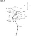
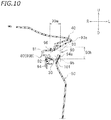
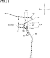
- FIG. 7 , FIG. 8 , FIG. 9 , FIG. 10 , FIG. 11 and FIG. 12 are a cross-sectional view taken along line VII-VII of FIG. 4 , a cross-sectional view taken along line VIII-VIII, a cross-sectional view taken along line IX-IX, a cross-sectional view taken along line X-X, a cross-sectional view taken along line XI-XI and a cross-sectional view taken along line XII-XII, respectively.
- FIG. 7 to FIG. 12 are vertical cross-sectional views. As shown in FIG.
- the groove portion 90 includes a vertical wall 92, an upper wall 93 extending outward in the vehicle width direction from the upper end of the vertical wall 92, and a lower wall 94 extending outward in the vehicle width direction from the lower end of the vertical wall 92.
- the groove portion 90 is a portion that is partitioned by the vertical wall 92, the upper wall 93 and the lower wall 94.
- each of the vertical wall 92, the upper wall 93 and the lower wall 94 may be formed of a single member or may be formed of a plurality of members.
- the upper wall 93 is formed of an upper wall 93a, which is formed of a portion of the front cover 30, and an upper wall 93b, which is formed of a portion of the upper cover 40.
- the lower wall 94 is formed of a lower wall 94a, which is formed of a portion of the front cover 30, and a lower wall 94b, which is formed of a portion of the under cover 50. That is, the upper wall 93 and the lower wall 94 are each formed of two members.
- the air flows through the groove portion 90 from the front side toward the rear side.
- the groove portion 90 forms an air passage 101 through which the air flows.
- a region that is surrounded by the vertical wall 92, the upper wall 93, the lower wall 94 and a vertical line 95 is regarded as the air passage 101.
- the vertical line 95 is a vertical line that passes through one of an outer end 93e of the upper wall 93 in the vehicle width direction and an outer end 94e of the lower wall 94 in the vehicle width direction that is located more inward in the vehicle width direction.
- the outer end 94e of the lower wall 94 is located rightward relative to the outer end 93e of the upper wall 93.
- the outer end 94e of the lower wall 94 is located more inward in the vehicle width direction than the outer end 93e of the upper wall 93.
- the vertical line 95 passes through the outer end 94e of the lower wall 94.
- the groove portion 90 includes an inlet opening 96 for the air.
- the inlet opening 96 is connected to the guide passage 81 (see FIG. 3 ).
- the inlet opening 96 communicates with the cooling passage 100 via the guide passage 81.
- the inlet opening 96 is formed upward and forward relative to the radiator 8.
- the inlet opening 96 is formed in the upper wall 93 of the groove portion 90 (see FIG. 10 ).
- the dimension 90h of the groove portion 90 in the up-down direction decreases from the front end portion 91 toward the inlet opening 96.
- the dimension 90w of the groove portion 90 in the vehicle width direction decreases from the front end portion 91 toward the inlet opening 96.
- the area of passage cross-section of the groove portion 90 (in other words, the passage cross-sectional area of the air passage 101) gradually decreases from the front end portion 91 toward the inlet opening 96.
- the area of passage cross-section passing through the center of the inlet opening 96 of the groove portion 90 is smaller than the area of passage cross-section passing through the front end portion 91 of the groove portion 90.
- the area of passage cross-section of the groove portion 90 refers to the area of a region of the vertical cross section of the groove portion 90 that is surrounded by the vertical wall 92, the upper wall 93, the lower wall 94 and the vertical line 95. Since the area of passage cross-section of the groove portion 90 gradually decreases from the front end portion 91 toward the inlet opening 96, the air flowing through the groove portion 90 is gradually compressed from the front end portion 91 toward the inlet opening 96.
- the inlet opening 96 is facing outward in the vehicle width direction as the vehicle is seen from the side.
- the inlet opening 96 is facing leftward as the vehicle is seen from the side.
- the groove portion 90 is inclined relative to the horizontal line HL so as to descend while extending from the front end portion 91 toward the inlet opening 96. Since the inlet opening 96 is formed in the upper wall 93, the inlet opening 96 has its opening facing forward as the vehicle is seen from the front.
- the dimension of the inlet opening 96 in the front-rear direction is greater than either one of the dimension in the left-right direction and the dimension in the up-down direction.
- the upper end of the under cover 50 is located upward relative to the vertical wall 92 between the front end portion 91 of the groove portion 90 and the inlet opening 96.
- the outside of the vertical wall 92 in the vehicle width direction is covered by the under cover 50. Note, however, that there is no particular limitation on the configuration.
- a portion of the guide passage 81 is partitioned by the guide passage portion 80B of the support cover 80 and the outer cover 60.
- a portion of the outer cover 60 partitions between the guide passage 81 and the outside.
- the air for cooling the ECU 9 flows inward of the portion of the outer cover 60 in the vehicle width direction, and the outside air flows outward of the portion of the outer cover 60 in the vehicle width direction.
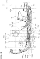
- FIG. 14 is a cross-sectional view taken along line XIV-XIV of FIG. 4 .
- the groove portion 90 is formed by the front cover 30, the upper cover 40 and the under cover 50, and the groove portion 90 defines the air passage 101.
- the support cover 80 is arranged inward in the vehicle width direction relative to the groove portion 90.
- the support cover 80, the front cover 30, the upper cover 40 and the outer cover 60 form the tubular air passage 110 through which the air supplied to the ECU 9 passes.
- the air passage 110 includes the cooling passage 100 that cools the ECU 9, and the guide passage 81 that communicates together the groove portion 90 and the cooling passage 100.
- the radiator 8 includes a core portion 8A that exchanges heat between the coolant and the air, a tank portion 8B that is located sideward, left and right, of the core portion 8A, and a bracket portion (not shown).
- the straight lines 91 L and 91 bL of FIG. 14 are straight lines respectively indicating the positions in the front-rear direction of the front end portion 91 and the rear end portion 91b of the groove portion 90.
- the straight lines 80fL and 80bL are straight lines respectively indicating the positions in the front-rear direction of a front end portion 80f and a rear end portion 80b of the support cover 80.
- the straight lines 96fL and 96bL are straight lines respectively indicating the positions in the front-rear direction of a front end portion 96f and a rear end portion 96b of the inlet opening 96.
- the straight lines 8fL and 8bL are straight lines respectively indicating the positions in the front-rear direction of the front end portion and the rear end portion of the core portion 8A of the radiator 8.
- the front end portion 91 of the groove portion 90, the front end portion 80f of the support cover 80, the front end portion 96f of the inlet opening 96, the rear end portion 96b of the inlet opening 96, the front end portion of the core portion 8A of the radiator 8, the rear end portion of the core portion 8A of the radiator 8 and the rear end portion 80b of the support cover 80 are located in this order from the front side toward the rear side.
- the inlet opening 96 is provided rearward relative to a middle position 91m in the front-rear direction between the front end portion 91 and the rear end portion 91b of the groove portion 90 (see FIG. 16 ).
- the distance in the front-rear direction between the rear end portion 96b of the inlet opening 96 and the rear end portion 91b of the groove portion 90 is shorter than the distance in the front-rear direction between the front end portion 96f of the inlet opening 96 and the front end portion 91 of the groove portion 90.
- the front end portion 96f of the inlet opening 96 is located forward relative to the front end portion of the core portion 8A of the radiator 8.
- the rear end portion 96b of the inlet opening 96 is located forward relative to the rear end portion of the core portion 8A of the radiator 8. In the present embodiment, the rear end portion 96b of the inlet opening 96 is located forward relative to the front end portion of the core portion 8A of the radiator 8.
- the straight lines 8AM and 8BM of FIG. 14 are straight lines respectively indicating the positions in the vehicle width direction of the outer ends of the core portion 8A and the tank portion 8B of the radiator 8.
- the straight lines 96fM and 96bM are straight lines respectively indicating positions in the vehicle width direction of the front end portion 96f and the rear end portion 96b of the inlet opening 96.
- the outer end portion of the core portion 8A of the radiator 8 in the vehicle width direction, the outer end portion of the tank portion 8B in the vehicle width direction, the front end portion 96f of the inlet opening 96 and the rear end portion 96b of the inlet opening 96 are located in this order from the inner side toward the outer side in the vehicle width direction.
- the front end portion 96f of the inlet opening 96 is located inward in the vehicle width direction relative to the rear end portion 96b of the inlet opening 96.
- the front end portion 96f of the inlet opening 96 is located outward in the vehicle width direction relative to the outer end portion of the core portion 8A of the radiator 8 in the vehicle width direction.
- the front end portion 96f of the inlet opening 96 is located outward in the vehicle width direction relative to the outer end portion of the tank portion 8B of the radiator 8 in the vehicle width direction.
- the air flowing along the groove portion 90 i.e., the air flowing through the air passage 101
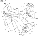
- FIG. 15 is a perspective view showing a main part of the motorcycle 1 as seen from a diagonal rear upper direction. As shown in FIG. 15 , a rear edge portion 61 of the outer cover 60 is spaced apart from the rear cover 70 in the outward direction in the vehicle width direction. A gap 98 is formed between the outer cover 60 and the rear cover 70. The gap 98 functions as an outlet port that allows the air to flow out of the air passage 110. Hereinafter, the gap 98 will be referred to as a first outlet port 98.
- a second outlet port 99 that allows the air to flow out of the air passage 110 is formed in a portion of the outer cover 60 that is upward relative to the first outlet port 98.
- the number herein is three.
- Three second outlet ports 99 are arranged next to each other in the front-rear direction.
- the ECU 9 is formed in a rectangular shape having the front edge 9f, the rear edge 9r, the upper edge 9u and the lower edge 9d as the vehicle is seen from the side.
- the first outlet port 98 is located between the downward extension 9fe of the front edge 9f and the downward extension 9re of the rear edge 9r and downward relative to the lower edge 9d.
- the second outlet port 99 is located between the rearward extension 9ue of the upper edge 9u and the rearward extension 9de of the lower edge 9d and rearward relative to the rear edge 9r.
- the motorcycle 1 is configured as described above. As the motorcycle 1 runs, the air flows through the air passage 101 and the air passage 110, and the ECU 9 is cooled by the air. Next, the flow of the air that is generated from the running of the motorcycle 1 will be described.
- the air flows through the motorcycle 1 from the front side toward the rear side.
- a portion of the air enters the inside of the groove portion 90 through the front end portion 91 of the groove portion 90.
- the area of passage cross-section of the groove portion 90 decreases from the front end portion 91 toward the inlet opening 96. Therefore, the air A1 in the groove portion 90 (see FIG. 15 ) is compressed before reaching the inlet opening 96.
- a portion of the air A1 flowing through the groove portion 90 flows into the guide passage 81 of the air passage 110 from the inlet opening 96.
- the air A2 which has flown into the guide passage 81 (see FIG. 3 and FIG. 15 ) flows into the cooling passage 100 after flowing through the guide passage 81.
- the air A3 which has flown into the cooling passage 100 flows around the ECU 9.
- the ECU 9 is cooled by the air A3.
- a portion A31 of the air which has cooled the ECU 9 flows out of the cooling passage 100 through the first outlet port 98, and another portion A32 flows out of the cooling passage 100 through the second outlet port 99.
- the flow velocity of the air B1 is higher than the flow velocity of the air A31. Therefore, the air A31 is accelerated by the air B1, thereby promoting the air 31 to flow out through the first outlet port 98.
- FIG. 16 is a diagram schematically showing a configuration of a part of FIG. 14 .
- a portion of the air flowing rearward along the groove portion 90 (in other words, the air flowing through the air passage 101) flows into the guide passage 81 of the air passage 110 through the inlet opening 96, and the remaining air flows rearward along the outer surface of the outer cover 60 from the rear end portion 91b of the groove portion 90.
- the compressed air passing through the groove portion 90 generates a force F1 pressing the front cover 30 and the upper cover 40 forming the groove portion 90 inward in the vehicle width direction.
- the outer cover 60 is attached as if it were sandwiched between two of a plurality of covers forming the air passage 101 and the air passage 110. In the cross-section shown in FIG. 13 , a portion 60j of the outer cover 60 is sandwiched between the support cover 80 and the front cover 30. Note that a portion of the outer cover 60 may be sandwiched between the upper cover 40 and the support cover 80 or may be sandwiched between the front cover 30 and the upper cover 40.
- a bent portion 90g that is bent inward in the vehicle width direction is provided at the rear end portion 91b of the groove portion 90.
- a portion of the front cover 30 forms the bent portion 90g.
- a front end portion 60g of the outer cover 60 is arranged rearward of the bent portion 90g.
- the front end portion 60g of the outer cover 60 is arranged inward in the vehicle width direction relative to an inner edge portion 90n of the groove portion 90 (note that the straight line 90nL is a straight line indicating the position of the inner edge portion 90n in the vehicle width direction).
- the outer cover 60 is curved outward in the vehicle width direction while extending rearward from the front end portion 60g (see FIG. 14 ).
- the air B1 flowing along the outer surface of the outer cover 60 generates a force F2 pressing the outer cover 60 inward in the vehicle width direction.
- the guide passage 81 is bent outward in the vehicle width direction while extending rearward (see FIG. 14 ). Therefore, the air A2 flowing into the guide passage 81 through the inlet opening 96 presses the outer cover 60 outward in the vehicle width direction while flowing through the guide passage 81. Therefore, the air A2 flowing through the guide passage 81 generates a force F3 urging to pull off the outer cover 60 outward in the vehicle width direction.
- the flow velocity of the air A2 flowing through the guide passage 81 is greater than the flow velocity of the air B1 flowing along the outer surface of the outer cover 60. Therefore, the pressure of the air A2 in the guide passage 81, i.e. the pressure of the air A2 inside the outer cover 60, is smaller than the pressure of the air B1 outside the outer cover 60. As a result, due to the pressure difference between the inside and the outside of the outer cover 60 consequently applies a force on the outer cover 60 from the outer side to the inner side in the vehicle width direction. Therefore, without increasing the rigidity of a member that supports the outer cover 60 or the outer cover 60 itself, it is possible to prevent the outer cover 60 from coming off outward in the vehicle width direction.
- the ECU 9 is arranged sideward of the engine 7, but the support cover 80 is arranged between the engine 7 and the ECU 9 (see FIG. 5 ).
- the ECU 9 is prevented from being heated directly by the engine 7.
- the front cover 30, the upper cover 40 and the under cover 50 together form the groove portion 90 through which the air flows while running.
- the air flows rearward from the front end portion 91 of the groove portion 90.
- the front end portion 91 of the groove portion 90 is located upward and forward relative to the radiator 8. Therefore, the air not influenced by the heat of the radiator 8 flows into the groove portion 90.
- the air flows around the ECU 9, thereby cooling the ECU 9.
- the air not influenced by the heat generated from the radiator 8 or the heated exhaust air having been passing through the radiator 8 flows through the air passage 110 for cooling the ECU 9. Therefore, it is possible to effectively cool the ECU 9.
- the area of passage cross-section passing through the center of the inlet opening 96 of the groove portion 90 is smaller than the area of passage cross-section passing through the front end portion 91.
- the air introduced into the groove portion 90 is compressed while reaching the inlet opening 96 from the front end portion 91. Then, the compressed air is guided into the air passage 110 through the inlet opening 96. Since the amount of air flowing through the air passage 110 increases, it is possible to effectively cool the ECU 9.
- the inlet opening 96 formed in the groove portion 90 is located upward and forward relative to the radiator 8.
- the inlet opening 96 is located forward and outward in the vehicle width direction relative to the radiator 8. Therefore, the air flowing into the inlet opening 96 is unlikely to be influenced by the heat of the radiator 8. It is possible to further reduce the influence of the heat of the radiator 8 for the air introduced into the air passage 110. Therefore, it is possible to more effectively cool the ECU 9.
- the radiator 8 is arranged downward relative to the groove portion 90.
- One of the vertical wall 92, the upper wall 93 and the lower wall 94 forming the groove portion 90 that is farthest away from the radiator 8 is the upper wall 93.
- the inlet opening 96 is formed in the upper wall 93.
- the air is guided to the air passage 110 from a portion of the groove portion 90 that is away from the radiator 8. Therefore, it is possible to further reduce the influence of the heat of the radiator 8 for the air for cooling the ECU 9. Therefore, it is possible to more effectively cool the ECU 9.
- the air is guided into the groove portion 90 from the front end portion 91 of the groove portion 90 whose opening is facing forward.
- dust or rain, etc. may also possibly enter the groove portion 90 together with the air.
- the ECU 9 is exposed to dust or rain. Being heavier than the air, dust or rain tends to flow through a lower portion of the groove portion 90 as compared with the air.
- the inlet opening 96 is formed in the upper wall 93, it is possible to suppress the entry of dust or rain into the air passage 110. Dust or rain is likely to be guided along the lower wall 94 of the groove portion 90 to be discharged rearward of the groove portion 90.
- the portion where the inlet opening 96 is formed is not limited to the upper wall 93.
- the inlet opening 96 may be formed in the vertical wall 92 or the lower wall 94. While a portion of the air flowing through the groove portion 90 flows into the inlet opening 96, another portion thereof flows rearward past the inlet opening 96. The air flowing through the groove portion 90 flows along the vertical wall 92, the upper wall 93 and the lower wall 94.
- the inlet opening 96 is formed in the vertical wall 92, the upper wall 93 or the lower wall 94 of the groove portion 90, the air flowing through the groove portion 90 is unlikely to be hindered by the inlet opening 96. Thus, it is possible to suppress the inlet opening 96 presenting an air resistance.
- the groove portion 90 is inclined relative to the horizontal line HL so as to descend while extending from the front end portion 91 toward the inlet opening 96.
- the inlet opening 96 formed in the upper wall 93 is facing forward as the vehicle is seen from the front. Therefore, the air flowing through the groove portion 90 is likely to flow into the inlet opening 96. It is possible to increase the amount of air to be guided to the air passage 110. Therefore, it is possible to more effectively cool the ECU 9. It is also possible to further suppress the entry of dust or rain into the air passage 110.
- the support cover 80 includes the guide passage portion 80B formed with the guide passage 81, in addition to the control unit attachment portion 80A to which the ECU 9 is attached.
- the air having flown through the groove portion 90 flows into the guide passage 81 through the inlet opening 96 and is guided to the cooling passage 100 from the guide passage 81.
- the guide passage 81 provided forward of the cooling passage 100, it is possible to form the inlet opening 96 at a more forward position. Therefore, the air unlikely to be influenced by the heat of the radiator 8 is introduced into the air passage 110 for cooling the ECU 9. Therefore, it is possible to effectively cool the ECU 9.
- the first outlet port 98 that allows the air to flow out of the air passage 110 is formed between the outer cover 60 and the rear cover 70.
- the air B1 flows rearward on the outer side of the outer cover 60 in the vehicle width direction.
- the flow of the air B1 serves to suck out the air A31 from the cooling passage 100 through the first outlet port 98. Since the air A31 of the cooling passage 100 is likely to flow out of the first outlet port 98, the flow velocity of the air A31 through the cooling passage 100 is increased. Therefore, it is possible to effectively cool the ECU 9.
- the second outlet port 99 is formed in a portion of the outer cover 60 that is upward of the first outlet port 98.
- the second outlet port 99 is formed, in addition to the first outlet port 98, in the air passage 110. Even when a large amount of air flows into the air passage 110, the air flows out not only through the first outlet port 98 but also through the second outlet port 99, and thus smoothly flows out of the air passage 110. The air is unlikely to stagnate in the air passage 110. Therefore, it is possible to effectively cool the ECU 9.
- the ECU 9 is formed in a rectangular shape having the front edge 9f, the rear edge 9r, the upper edge 9u and the lower edge 9d as the vehicle is seen from the side.
- the first outlet port 98 is located between the downward extension 9fe of the front edge 9f and the downward extension 9re of the rear edge 9r and downward relative to the lower edge 9d. It is made easier for a portion of the air in the cooling passage 100 to flow downward through the lower edge 9d. The air is likely to flow around the ECU 9 in accordance with the shape of the ECU 9. Therefore, it is possible to effectively cool the ECU 9.
- the second outlet port 99 is located between the rearward extension 9ue of the upper edge 9u and the rearward extension 9de of the lower edge 9d and rearward relative to the rear edge 9r. It is made easier for another portion of the air in the cooling passage 100 to flow rearward through the rear edge 9r. The air is likely to flow around the ECU 9 in accordance with the shape of the ECU 9. Therefore, it is possible to effectively cool the ECU 9.
- the motorcycle 1 according to one embodiment has been described above. However, the embodiment is merely an example, and various other embodiments are possible. Next, other embodiment examples will be described briefly.
- the vehicle part arranged sideward of the engine 7 is not limited to the ECU 9.
- the vehicle part may be a regulator, a battery, etc.
- the present invention is able to be applied to various vehicle parts that should be prevented from becoming hot.
- the front cover 30, the upper cover 40, the under cover 50, the outer cover 60, the rear cover 70 and the support cover 80 do not always need to be formed of a single member.
- One or two or more of the front cover 30, the upper cover 40, the under cover 50, the outer cover 60, the rear cover 70 and the support cover 80 may be formed of two or more members.
- the front cover 30, the upper cover 40, the under cover 50, the outer cover 60, the rear cover 70 and the support cover 80 do not always need to be separate from each other.
- One or two or more of the front cover 30, the upper cover 40, the under cover 50, the outer cover 60, the rear cover 70 and the support cover 80 may be formed of a single member.
- the material of the front cover 30, the upper cover 40, the under cover 50, the outer cover 60, the rear cover 70 and the support cover 80 there is no particular limitation on the material of the front cover 30, the upper cover 40, the under cover 50, the outer cover 60, the rear cover 70 and the support cover 80. These materials may be a synthetic resin or may be a metal, for example. Two or more of the front cover 30, the upper cover 40, the under cover 50, the outer cover 60, the rear cover 70 and the support cover 80 may be of the same material or may be of different materials.
- the area of passage cross-section of the groove portion 90 does not always need to gradually decrease from the front end portion 91 toward the inlet opening 96.
- the area may gradually decrease from the front end portion 91 toward the inlet opening 96, and then gradually increase and decrease again.
- the area of passage cross-section of the groove portion 90 may be constant or may increase from the front end portion 91 toward the inlet opening 96.
- the area of passage cross-section passing through the center of the inlet opening 96 of the groove portion 90 does not always need to be smaller than the area of passage cross-section passing through the front end portion 91.
- the dimension of the groove portion 90 in the up-down direction does not always need to decrease from the front end portion 91 toward the inlet opening 96.
- the dimension of the groove portion 90 in the left-right direction does not always need to decrease from the front end portion 91 toward the inlet opening 96.
- the position of the inlet opening 96 is not always limited to be upward and forward relative to the radiator 8.
- the position of the inlet opening 96 may be rearward relative to the front end of the radiator 8.
- the inlet opening 96 does not always need to be formed in the upper wall 93 of the groove portion 90.
- the inlet opening 96 may be formed in the vertical wall 92 or the lower wall 94.
- the inlet opening 96 may be formed to extend from the upper wall 93 to the vertical wall 92 or may be formed to extend from the vertical wall 92 to the lower wall 94.
- the groove portion 90 does not always need to be inclined relative to the horizontal line HL so as to descend while extending from the front end portion 91 to the inlet opening 96.
- the groove portion 90 may be inclined relative to the horizontal line HL so as to ascend while extending from the front end portion 91 to the inlet opening 96.
- the groove portion 90 may be parallel to the horizontal line HL.
- the rear cover 70 is not always necessary. When the rear cover 70 is absent, for example, the gap between the rear edge of the support cover 80 and the rear edge of the outer cover 60 forms the first outlet port 98.
- first outlet port 98 and the second outlet port 99 there is no particular limitation on the positions of the first outlet port 98 and the second outlet port 99 relative to the ECU 9.
- One of the first outlet port 98 and the second outlet port 99 may be omitted.
- another outlet port may be included that allows the air to flow out of the air passage 110.
- tank portion 8B of the radiator 8 is arranged leftward and rightward of the core portion 8A in the embodiment described above, there is no particular limitation on the configuration.
- the tank portion 8B may be arranged upward and downward of the core portion 8A.
- a straddled vehicle refers to a vehicle that is straddled by a rider and/or passenger.
- a straddled vehicle is not limited to the motorcycle 1.
- a straddled vehicle may be an auto or motor tricycle, an ATV (All Terrain Vehicle), scooter, model, snow mobile or the like.
- the present invention includes any and all preferred embodiments including equivalent elements, modifications, omissions, combinations, adaptations and/or alterations as would be appreciated by those skilled in the art on the basis of the present disclosure.
- the limitations in the claims are to be interpreted broadly based on the language included in the claims and not limited to examples described in the present specification or during the prosecution of the application.
Landscapes
- Engineering & Computer Science (AREA)
- Mechanical Engineering (AREA)
- Chemical & Material Sciences (AREA)
- Combustion & Propulsion (AREA)
- General Engineering & Computer Science (AREA)
- Automatic Cycles, And Cycles In General (AREA)
Abstract
Description
- The present invention relates to a straddled vehicle, straddle-type vehicle or saddle-ride type vehicle.
- Conventional straddled vehicles are known in the art that include an internal combustion engine and an electronic control unit for controlling the internal combustion engine, etc., wherein the electronic control unit is arranged sideward of the internal combustion engine. With such a straddled vehicle, the electronic control unit can be arranged in the vicinity of the internal combustion engine. Now, since the electronic control unit includes electronic parts, the temperature of the electronic control unit should be prevented from becoming too high. If the electronic control unit is arranged in the vicinity of the internal combustion engine of a high temperature, the temperature thereof may become high.
- Japanese Laid-Open Patent Publication No.
2009-241803 2009-241803 - With the motorcycle disclosed in Japanese Laid-Open Patent Publication No.
2009-241803 - In order to increase the effect of cooling the electronic control unit, one may consider enlarging the inlet opening of the air passage. If the inlet opening is larger, the amount of air flowing through the air passage increases, and it is therefore possible to increase the effect of cooling the electronic control unit. However, if the amount of air flowing through the air passage increases, the pressure the side cover receives from the air increases. Therefore, it is necessary to increase the rigidity of a member that supports the side cover or the side cover itself so that the side cover does not come off outward in the vehicle width direction because of the air. This, as a result, may lead to an increase in the size or weight of the vehicle.
- That is, when the inlet opening provided in the side cover is enlarged in order to increase the amount of air supplied to the electronic control unit, it will be in a so-called "bulge shape". In this case, when running at a high speed, the air hits a portion of the inner wall of the side cover that is located rearward of the inlet opening. Thus, it is possible to introduce more air into the air passage. However, the structure of the side cover around the inlet opening is likely to be a resistance to the air. The air introduced to the side cover generates a force to pull off the side cover outward in the vehicle width direction. It is necessary to increase the rigidity of a member that supports the side cover or the side cover itself so that the side cover does not come off outward in the vehicle width direction because of the air. This as a result may lead to an increase in the size or weight of the vehicle.
- As another method for increasing the effect of cooling the electronic control unit, one may consider orienting the inlet opening of the air passage downward so that the air having been influenced by the heat of the radiator, i.e. the warmed air does not come into the air passage. However, while the motorcycle runs, the air flows from the front side toward the rear side, and it is difficult to take in a large amount of air through an inlet opening facing downward. Therefore, the amount of air flowing through the air passage may become insufficient, failing to increase the effect of cooling the electronic control unit.
- Note that in a straddled vehicle, vehicle parts of which the temperature should be prevented from becoming high are not limited to the electronic control unit. For example, the regulator and the battery are also vehicle parts of which the temperature should be prevented from becoming high. Similar problems occur when such vehicle parts are arranged sideward of the internal combustion engine.
- It is an object of at least one embodiment of at least one aspect of the present invention to obviate or at least mitigate one or more problems or disadvantages in the prior art.
- It is an object of at least one embodiment of at least one aspect of the present invention - which has been made in order to seek to address the aforementioned problem - to provide a straddled vehicle including a radiator arranged forward of the internal combustion engine and a vehicle part arranged sideward of the internal combustion engine, wherein it is possible to effectively cool the vehicle part.
- According to an aspect of the present invention there is provided a straddled vehicle according to the appended claims.
- According to an embodiment of the present invention there is provided a straddled vehicle. The straddled vehicle may comprise one or more of:
- a vehicle frame which may include a head pipe;
- an internal combustion engine which may be supported on the vehicle frame;
- a radiator which may be supported on the vehicle frame and/or arranged forward relative to the internal combustion engine;
- a support cover which may be arranged sideward of the internal combustion engine;
- a vehicle part which may be supported on the support cover and/or arranged outward in a vehicle width direction relative to the support cover, wherein at least a portion of the vehicle part may overlap with the internal combustion engine as the vehicle is seen from the side;
- a front cover at least a portion of which may be arranged forward of the head pipe;
- an upper cover at least a portion of which may be arranged sideward of the head pipe and upward relative to the radiator;
- an under cover (or lower cover) at least a portion of which may be arranged sideward of the head pipe and downward of the upper cover; and/or
- an outer cover which may be arranged outward of the support cover and/or the vehicle part in the vehicle width direction.
- A groove portion may be formed by at least one of the front cover, the upper cover and the under cover, wherein the groove portion may include a front end portion which may be located upward and forward relative to the radiator and/or a rear end portion which may be located rearward relative to the front end portion, and wherein the groove portion may extend rearward from the front end portion to the rear end portion and is depressed inward in the vehicle width direction.
- At least a portion of a tubular air passage through which air supplied to the vehicle part may pass may be formed by the support cover and/or the outer cover.
- The front end portion of the groove portion may have an opening facing forward as the vehicle is seen from the side.
- An air inlet opening that communicates with the air passage may be formed in the groove portion.
- With the straddled vehicle described above, the vehicle part may be arranged sideward of the internal combustion engine, but the support cover may be arranged between the internal combustion engine and the vehicle part. Therefore, the vehicle part may be prevented from being heated directly by the internal combustion engine. As the straddled vehicle runs, the air may flow through the groove portion from the front end portion toward the rear side. Herein, the front end portion of the groove portion may be located upward and forward relative to the radiator. Therefore, the air not influenced by the heat of the radiator may be introduced into the groove portion. The air introduced into the groove portion may be guided into the air passage, at least a portion of which may be formed between the support cover and the outer cover through the inlet opening. The vehicle part may be cooled by the air flowing through the air passage. With the straddled vehicle, the air not influenced by the heat of the radiator may flow through the air passage for cooling the vehicle part. Therefore, it may be possible to effectively cool the vehicle part.
- According to one preferred embodiment of the present invention, an area of passage cross-section passing through a center of the inlet opening of the groove portion may be smaller than an area of passage cross-section passing through the front end portion of the groove portion.
- Note that there may be no particular limitation on the shape of the groove portion. For example, the dimension of the groove portion in the up-down direction may decrease from the front end portion toward the inlet opening. The dimension of the groove portion in the vehicle width direction may decrease from the front end portion toward the inlet opening.
- According to the embodiment described above, the air introduced into the groove portion from the front end portion of the groove portion may be compressed before reaching the inlet opening. Then, the compressed air may be guided into the air passage through the inlet opening. Since the amount of air flowing through the air passage increases, it may be possible to more effectively cool the vehicle part.
- According to one (preferred) embodiment of the present invention, the inlet opening may be formed upward and forward relative to the radiator.
- According to the embodiment described above, it may be possible to further reduce the influence of the heat of the radiator for the air introduced into the air passage. Therefore, it may be possible to more effectively cool the vehicle part.
- According to one (preferred) embodiment of the present invention, the inlet opening may be formed forward and outward in the vehicle width direction relative to the radiator.
- According to the embodiment described above, it may be possible to further reduce the influence of the heat of the radiator for the air introduced into the air passage. Therefore, it is possible to more effectively cool the vehicle part.
- According to one (preferred) embodiment of the present invention, the groove portion may include a vertical wall, an upper wall extending outward in the vehicle width direction from an upper end of the vertical wall, and a lower wall extending outward in the vehicle width direction from a lower end of the vertical wall. The inlet opening may be formed in the upper wall.
- The radiator may be arranged downward relative to the groove portion. One of the vertical wall, the upper wall and the lower wall of the groove portion that is farthest away from the radiator may be the upper wall. According to the embodiment described above, the air may be guided to the air passage from a portion of the groove portion that is away from the radiator, and therefore it may be possible to further reduce the influence of the heat of the radiator. Therefore, it may be possible to more effectively cool the vehicle part. The air may be guided into the groove portion from the front end portion of the groove portion whose opening may be facing forward. Then, dust or rain, etc., may also possibly enter the groove portion together with the air. It is not preferred that the vehicle part is exposed to dust or rain. Being heavier than the air, dust or rain tends to flow through a lower portion of the groove portion as compared with the air. According to the embodiment described above, since the inlet opening may be formed in the upper wall, it may be possible to suppress the entry of dust or rain into the air passage. Dust or rain is likely to be guided along the lower wall of the groove portion to be discharged rearward of the groove portion.
- According to one (preferred) embodiment of the present invention, the groove portion may be inclined relative to a horizontal line so as to descend while extending from the front end portion toward the inlet opening.
- According to the embodiment described above, since the groove portion may be inclined relative to the horizontal line, the air flowing through the groove portion may be likely to flow into the inlet opening formed in the upper wall. It may be possible to increase the amount of air to be guided to the air passage. Therefore, it may be possible to more effectively cool the vehicle part. It may also be possible to further suppress the entry of dust or rain into the air passage.
- According to one (preferred) embodiment of the present invention, the support cover may include a vehicle part attachment portion to which the vehicle part is attached, and a guide passage portion which may be arranged forward of the vehicle part attachment portion and inward in the vehicle width direction of the upper cover. A guide passage that guides air from the inlet opening toward the vehicle part may be formed in the guide passage portion.
- According to the embodiment described above, the air in the groove portion may flow into the guide passage through the inlet opening and may be guided by the guide passage toward the vehicle part. According to the embodiment described above, the inlet opening may be able to be provided at a more forward position. Therefore, the air unlikely to be influenced by the heat of the radiator may be able to be introduced into the air passage. Therefore, it may be possible to more effectively cool the vehicle part.
- According to one preferred embodiment of the present invention, the straddled vehicle may include a rear cover arranged rearward of the vehicle part. A first outlet port that allows air to flow out of the air passage may be formed between the outer cover and the rear cover.
- As the straddled vehicle runs, the air may flow rearward along the outer surface of the outer cover. The flow of the air may serve to suck out the air from the air passage through the first outlet port. Since the air of the air passage may be likely to flow out of the first outlet port, the flow velocity of the air through the air passage may be increased. Therefore, it may be possible to more effectively cool the vehicle part.
- According to one (preferred) embodiment of the present invention, a second outlet port that allows air to flow out of the air passage may be formed in a portion of the outer cover that is upward relative to the first outlet port.
- According to the embodiment described above, the second outlet port may be formed, in addition to the first outlet port, in the air passage. Even when a large amount of air flows into the air passage, the air may smoothly flow out of the air passage. The air flowing through the air passage is unlikely to stagnate. Therefore, it may be possible to more effectively cool the vehicle part.
- According to one (preferred) embodiment of the present invention, the vehicle part may be formed in a rectangular shape having a front edge, a rear edge, an upper edge and a lower edge as the vehicle is seen from the side. At least a portion of the first outlet port may be located between a downward extension of the front edge and a downward extension of the rear edge and downward relative to the lower edge as the vehicle is seen from the side.
- According to the embodiment described above, the air of the air passage may be likely to flow around the vehicle part in accordance with the shape of the vehicle part. Therefore, it may be possible to effectively cool the vehicle part.
- According to one (preferred) embodiment of the present invention, the vehicle part may be formed in a rectangular shape having a front edge, a rear edge, an upper edge and a lower edge as the vehicle is seen from the side. At least a portion of the second outlet port may be located between a rearward extension of the upper edge and a rearward extension of the lower edge and rearward relative to the rear edge as the vehicle is seen from the side.
- According to the embodiment described above, the air of the air passage may be likely to flow around the vehicle part in accordance with the shape of the vehicle part. Therefore, it may be possible to effectively cool the vehicle part.
- According to one preferred embodiment of the present invention, the vehicle part may be an electronic control unit that may control the internal combustion engine.
- The electronic control unit may be a vehicle part of which the temperature should particularly be prevented from increasing. According to the embodiment described above, it may be possible to effectively cool the electronic control unit. Even though the electronic control unit may be arranged sideward of the internal combustion engine, it may be possible to sufficiently suppress an increase in the temperature of the electronic control unit.
- According to at least one embodiment of the present invention it is possible to provide a straddled vehicle including a radiator arranged forward of the internal combustion engine and a vehicle part arranged sideward of the internal combustion engine, wherein it is possible to effectively cool the vehicle part.
- An embodiment of the present invention will now be described by way of example only, with reference to the accompany drawings, which are:
-
FIG. 1 a left side view of a motorcycle according to an embodiment; -
FIG. 2 a front view of the motorcycle according to an embodiment; -
FIG. 3 a left side view of a vehicle frame, a front cover, a support cover and an ECU; -
FIG. 4 a left side view of a main part of a motorcycle; -
FIG. 5 a cross-sectional view taken along line V-V ofFIG. 4 ; -
FIG. 6 an enlarged left side view of a main part of a motorcycle; -
FIG. 7 a cross-sectional view taken along line VII-VII ofFIG. 4 ; -
FIG. 8 a cross-sectional view taken along line VIII-VIII ofFIG. 4 ; -
FIG. 9 a cross-sectional view taken along line IX-IX ofFIG. 4 ; -
FIG. 10 a cross-sectional view taken along line X-X ofFIG. 4 ; -
FIG. 11 a cross-sectional view taken along line XI-XI ofFIG. 4 ; -
FIG. 12 a cross-sectional view taken along line XII-XII ofFIG. 4 ; -
FIG. 13 a cross-sectional view taken along line XIII-XIII ofFIG. 4 ; -
FIG. 14 a cross-sectional view taken along line XIV-XIV ofFIG. 4 ; -
FIG. 15 a perspective view of a main part of a motorcycle; and -
FIG. 16 a diagram schematically showing a configuration of a part ofFIG. 14 . - An embodiment of the present invention will now be described with reference to the accompanying drawings.
FIG. 1 is a left side view of a motorcycle 1 according to the present embodiment.FIG. 2 is a front view of the motorcycle 1. - The terms front, rear, left, right, up and down, as used in the description below, refer to these directions as seen from a virtual rider seated on a
seat 17 while the motorcycle 1 is standing upright on a horizontal surface with no rider and no load thereon, unless specified otherwise. The designations F, Re, L, R, U and D, as used in the figures, refer to front, rear, left, right, up and down, respectively. Unless specified otherwise, the term "front/forward" refers not only to the direction that extends in the front direction along the vehicle center line CL (seeFIG. 13 andFIG. 14 ), as the vehicle is seen from above, but also to directions that are inclined left/right from that direction by an angle that is less than or equal to 45 degrees. Similarly, the term "rear/rearward" refers not only to the direction that extends rearward along the vehicle center line CL, as the vehicle is seen from above, but also to directions that are inclined left/right from that direction by an angle of 45 degrees or less. The term "left/leftward" refers not only to the direction that extends leftward vertical to the vehicle center line CL, as the vehicle is seen from above, but also to directions that are inclined frontward/rearward from that direction by an angle of 45 degrees or less. The term "right/rightward" refers not only to the direction that extends rightward vertical to the vehicle center line CL, as the vehicle is seen from above, but also to directions that are inclined frontward/rearward from that direction by an angle of 45 degrees or less. The term "up/upward" refers not only to the vertically upward direction, as the vehicle is seen from sideways, but also to directions that are inclined frontward/rearward from that direction by an angle of 45 degrees or less. The term "down/downward" refers not only to the vertically downward direction, as the vehicle is seen from sideways, but also to directions that are inclined frontward/rearward from that direction by an angle of 45 degrees or less. - As shown in
FIG. 1 , the motorcycle 1 includes avehicle frame 3, afront wheel 5, arear wheel 6, an internal combustion engine (hereinafter "engine") 7, aradiator 8 and an electronic control unit (hereinafter "ECU") 9. The motorcycle 1 includes afuel tank 16 supported on thevehicle frame 3, and theseat 17 supported on thevehicle frame 3. Theseat 17 is arranged rearward of thefuel tank 16. - The
vehicle frame 3 includes ahead pipe 2, and amain frame 4 extending downward and rearward from thehead pipe 2. A steering shaft (not shown), to which ahandle 10 is secured, is supported on thehead pipe 2 so that the steering shaft is able to pivot left and right. The steering shaft is secured to afront fork 11. - The
front wheel 5 is supported on thefront fork 11. Therear wheel 6 is supported on a rear end portion of arear arm 12. The front end portion of therear arm 12 is supported by apivot shaft 13 so that therear arm 12 is able to pivot up and down relative to themain frame 4. Thefront wheel 5 is a driven wheel. Therear wheel 6 is a driving wheel that is driven by theengine 7. Theengine 7 and therear wheel 6 are linked by achain 14. Thechain 14 is an example of a power transmission member. Note, however, that the power transmission member that transmits the power of theengine 7 to therear wheel 6 is not limited to thechain 14, but it may be a transmission belt, a drive shaft, etc. - The
engine 7 is supported on thevehicle frame 3. Theengine 7 includes acrankcase 7A accommodating a crankshaft (not shown) therein, a cylinder body 7B connected to thecrankcase 7A (seeFIG. 3 ), and a cylinder head 7C connected to the cylinder body 7B. Although not shown in the figures, a cylinder that slidably accommodates a piston therein is provided inside the cylinder body 7B. An intake port and an exhaust port (not shown) are formed inside the cylinder head 7C. Theengine 7 is a water-cooled internal combustion engine. Although not shown in the figures, the cylinder body 7B and the cylinder head 7C are formed with a water jacket through which the coolant passes. - The
radiator 8 is connected to theengine 7 by a hose or a pipe (not shown). A coolant whose temperature has increased by cooling theengine 7 flows into theradiator 8. Theradiator 8 exchanges heat between the air passing through theradiator 8 from the front side toward the rear side and the coolant inside theradiator 8. The coolant inside theradiator 8 is cooled by the air outside theradiator 8. Conversely, the air outside theradiator 8 is heated by the coolant inside theradiator 8. The cooled coolant is passed from theradiator 8 to theengine 7 to again cool theengine 7. The heated air flows toward the rear side from theradiator 8. - The
ECU 9 is a vehicle part that controls theengine 7, for example. TheECU 9 includes an electronic circuit (not shown), etc. There is no limitation on the shape and the size of theECU 9. As shown inFIG. 3 , theECU 9 is formed in a rectangular shape as the vehicle is seen from the side. TheECU 9 has afront edge 9f, arear edge 9r, an upper edge 9u and alower edge 9d. At least a portion of theECU 9 overlaps with theengine 7 as the vehicle is seen from the side. Herein, a portion of theECU 9 overlaps with the cylinder head 7C as the vehicle is seen from the side. - Note that the rectangular shape as used herein is not limited to a rectangular shape in a strict sense but includes shapes that resemble a rectangular shape. In the present embodiment, the
front edge 9f, therear edge 9r and the upper edge 9u are formed to be linear as the vehicle is seen from the side, but thelower edge 9d is provided with indentations. Such a shape is included in the rectangular shape. Although not shown the figures, the four corners of theECU 9 may be rounded, for example. - As shown in
FIG. 1 , the motorcycle 1 includes afront cover 30, anupper cover 40, an under cover (or lower cover) 50, anouter cover 60 and arear cover 70. As shown inFIG. 3 , the motorcycle 1 further includes asupport cover 80. - As shown in
FIG. 3 , at least a portion of thefront cover 30 is arranged forward relative to thehead pipe 2. Thefront cover 30 includes ahole 31 through which a headlight 15 (seeFIG. 2 ) is inserted. As shown inFIG. 2 , thefront cover 30 includes anair introduction port 32 whose opening is facing forward as the vehicle is seen from the front. -
FIG. 4 is a left side view of a main part of the motorcycle 1. Specifically,FIG. 4 is a left side view of thehead pipe 2, themain frame 4, thefront cover 30, theupper cover 40, the undercover 50, theouter cover 60, thesupport cover 80 and therear cover 70. At least a portion of theupper cover 40 is arranged sideward of thehead pipe 2 and upward relative to theradiator 8. Theupper cover 40 includes avertical portion 40A extending upward, and ahorizontal portion 40B extending rearward from the lower end of thevertical portion 40A. - At least a portion of the
under cover 50 is arranged sideward of thehead pipe 2 and downward of theupper cover 40. The undercover 50 extends in a diagonal rear lower direction. - As shown in
FIG. 3 , thesupport cover 80 is arranged sideward of theengine 7. Thesupport cover 80 supports theECU 9. TheECU 9 is arranged leftward of thesupport cover 80. TheECU 9 is arranged outward in the vehicle width direction of thesupport cover 80. Note that the term "outward in the vehicle width direction" refers to the direction away from the vehicle center line CL (seeFIG. 13 andFIG. 14 ). The term "inward in the vehicle width direction" refers to the direction toward the vehicle center line CL. The vertical line CL1 ofFIG. 2 is a vertical line that is perpendicular to the vehicle center line CL. Thesupport cover 80 is arranged between theengine 7 and the ECU 9 (seeFIG. 5 ). Thesupport cover 80 serves to support theECU 9 and block theECU 9 from the heat of theengine 7. With thesupport cover 80 arranged between theengine 7 and theECU 9, theECU 9 is prevented from being heated directly from theengine 7. Thesupport cover 80 includes a controlunit attachment portion 80A to which theECU 9 is attached. - As shown in
FIG. 4 , theouter cover 60 is arranged outward in the vehicle width direction of thesupport cover 80 and theECU 9. Theouter cover 60 is arranged leftward of thesupport cover 80 and theECU 9. Theouter cover 60 covers the outside of theECU 9 in the vehicle width direction.FIG. 5 is a cross-sectional view taken along line V-V ofFIG. 4 . Acooling passage 100 through which the air for cooling theECU 9 passes is formed between the controlunit attachment portion 80A of thesupport cover 80 and theouter cover 60. At least a portion of theECU 9 is spaced apart from the controlunit attachment portion 80A of thesupport cover 80 and theouter cover 60. Thecooling passage 100 includes agap 100A between theECU 9 and theouter cover 60, and agap 100B between theECU 9 and the controlunit attachment portion 80A of thesupport cover 80. Note, however, that there is no particular limitation on the configuration. Thecooling passage 100 may include only one of thegaps - As shown in
FIG. 3 , thesupport cover 80 further includes aguide passage portion 80B provided forward of the controlunit attachment portion 80A. A portion of theguide passage portion 80B is arranged inward in the vehicle width direction of the upper cover 40 (seeFIG. 10 ). Another portion of theguide passage portion 80B is arranged inward in the vehicle width direction of the outer cover 60 (seeFIG. 12 ). Theguide passage portion 80B includes aguide passage 81 that is depressed inward in the vehicle width direction. Theguide passage 81 is connected to thecooling passage 100. Theguide passage 81 and thecooling passage 100 form atubular air passage 110. Where theair passage 110 is formed of a plurality of covers, there may be a gap between the covers. The term "tubular air passage" as used herein includes cases where there is such a gap. That is, the term "tubular air passage" as used herein includes both a tubular air passage whose periphery is airtight and a tubular air passage whose periphery partially has a gap. - As shown in
FIG. 4 , therear cover 70 is arranged rearward of theECU 9. A harness (not shown) is connected to theECU 9. The harness extends rearward from theECU 9. Therear cover 70 protects the harness. Therear cover 70 forms a harness cover. - The
front cover 30, theupper cover 40 and theunder cover 50 form agroove portion 90 that is depressed inward in the vehicle width direction. Herein, thegroove portion 90 is depressed rightward. Afront end portion 91 of thegroove portion 90 is located upward and forward relative to theradiator 8. As shown inFIG. 2 , thegroove portion 90 has its opening facing forward as the vehicle is seen from the front. As shown inFIG. 4 , thefront end portion 91 of thegroove portion 90 has its opening facing forward as the vehicle is seen from the side. Therefore, as the motorcycle 1 runs, the air flows toward thegroove portion 90 from the front side. - As shown in
FIG. 6 , thegroove portion 90 extends rearward from thefront end portion 91 to arear end portion 91b.FIG. 7 ,FIG. 8 ,FIG. 9 ,FIG. 10 ,FIG. 11 andFIG. 12 are a cross-sectional view taken along line VII-VII ofFIG. 4 , a cross-sectional view taken along line VIII-VIII, a cross-sectional view taken along line IX-IX, a cross-sectional view taken along line X-X, a cross-sectional view taken along line XI-XI and a cross-sectional view taken along line XII-XII, respectively.FIG. 7 to FIG. 12 are vertical cross-sectional views. As shown inFIG. 7 , thegroove portion 90 includes avertical wall 92, anupper wall 93 extending outward in the vehicle width direction from the upper end of thevertical wall 92, and alower wall 94 extending outward in the vehicle width direction from the lower end of thevertical wall 92. Conversely, thegroove portion 90 is a portion that is partitioned by thevertical wall 92, theupper wall 93 and thelower wall 94. - Each of the
vertical wall 92, theupper wall 93 and thelower wall 94 may be formed of a single member or may be formed of a plurality of members. In the cross-section shown inFIG. 7 , theupper wall 93 is formed of anupper wall 93a, which is formed of a portion of thefront cover 30, and anupper wall 93b, which is formed of a portion of theupper cover 40. Thelower wall 94 is formed of alower wall 94a, which is formed of a portion of thefront cover 30, and alower wall 94b, which is formed of a portion of theunder cover 50. That is, theupper wall 93 and thelower wall 94 are each formed of two members. - As the motorcycle 1 runs, the air flows through the
groove portion 90 from the front side toward the rear side. Thegroove portion 90 forms anair passage 101 through which the air flows. Herein, as shown inFIG. 7 , in the vertical cross-section of thegroove portion 90, a region that is surrounded by thevertical wall 92, theupper wall 93, thelower wall 94 and avertical line 95 is regarded as theair passage 101. Note that thevertical line 95 is a vertical line that passes through one of anouter end 93e of theupper wall 93 in the vehicle width direction and anouter end 94e of thelower wall 94 in the vehicle width direction that is located more inward in the vehicle width direction. Herein, theouter end 94e of thelower wall 94 is located rightward relative to theouter end 93e of theupper wall 93. Theouter end 94e of thelower wall 94 is located more inward in the vehicle width direction than theouter end 93e of theupper wall 93. Thevertical line 95 passes through theouter end 94e of thelower wall 94. - As shown in
FIG. 6 , thegroove portion 90 includes aninlet opening 96 for the air. Theinlet opening 96 is connected to the guide passage 81 (seeFIG. 3 ). Theinlet opening 96 communicates with thecooling passage 100 via theguide passage 81. As shown inFIG. 4 , theinlet opening 96 is formed upward and forward relative to theradiator 8. Theinlet opening 96 is formed in theupper wall 93 of the groove portion 90 (seeFIG. 10 ). - As shown in
FIG. 7 to FIG. 11 , thedimension 90h of thegroove portion 90 in the up-down direction decreases from thefront end portion 91 toward theinlet opening 96. Thedimension 90w of thegroove portion 90 in the vehicle width direction decreases from thefront end portion 91 toward theinlet opening 96. The area of passage cross-section of the groove portion 90 (in other words, the passage cross-sectional area of the air passage 101) gradually decreases from thefront end portion 91 toward theinlet opening 96. The area of passage cross-section passing through the center of the inlet opening 96 of thegroove portion 90 is smaller than the area of passage cross-section passing through thefront end portion 91 of thegroove portion 90. Note that the area of passage cross-section of thegroove portion 90 refers to the area of a region of the vertical cross section of thegroove portion 90 that is surrounded by thevertical wall 92, theupper wall 93, thelower wall 94 and thevertical line 95. Since the area of passage cross-section of thegroove portion 90 gradually decreases from thefront end portion 91 toward theinlet opening 96, the air flowing through thegroove portion 90 is gradually compressed from thefront end portion 91 toward theinlet opening 96. - As shown in
FIG. 6 , theinlet opening 96 is facing outward in the vehicle width direction as the vehicle is seen from the side. Herein, theinlet opening 96 is facing leftward as the vehicle is seen from the side. As shown inFIG. 6 , thegroove portion 90 is inclined relative to the horizontal line HL so as to descend while extending from thefront end portion 91 toward theinlet opening 96. Since theinlet opening 96 is formed in theupper wall 93, theinlet opening 96 has its opening facing forward as the vehicle is seen from the front. - Although there is no limitation on the shape and the dimension of the
inlet opening 96, the dimension of the inlet opening 96 in the front-rear direction is greater than either one of the dimension in the left-right direction and the dimension in the up-down direction. - As shown in
FIG. 7 to FIG. 9 , the upper end of theunder cover 50 is located upward relative to thevertical wall 92 between thefront end portion 91 of thegroove portion 90 and theinlet opening 96. The outside of thevertical wall 92 in the vehicle width direction is covered by theunder cover 50. Note, however, that there is no particular limitation on the configuration. - As shown in
FIG. 12 , a portion of theguide passage 81 is partitioned by theguide passage portion 80B of thesupport cover 80 and theouter cover 60. A portion of theouter cover 60 partitions between theguide passage 81 and the outside. The air for cooling theECU 9 flows inward of the portion of theouter cover 60 in the vehicle width direction, and the outside air flows outward of the portion of theouter cover 60 in the vehicle width direction. -
FIG. 14 is a cross-sectional view taken along line XIV-XIV ofFIG. 4 . As described above, thegroove portion 90 is formed by thefront cover 30, theupper cover 40 and theunder cover 50, and thegroove portion 90 defines theair passage 101. Thesupport cover 80 is arranged inward in the vehicle width direction relative to thegroove portion 90. Thesupport cover 80, thefront cover 30, theupper cover 40 and theouter cover 60 form thetubular air passage 110 through which the air supplied to theECU 9 passes. Theair passage 110 includes thecooling passage 100 that cools theECU 9, and theguide passage 81 that communicates together thegroove portion 90 and thecooling passage 100. - The
radiator 8 includes acore portion 8A that exchanges heat between the coolant and the air, atank portion 8B that is located sideward, left and right, of thecore portion 8A, and a bracket portion (not shown). Thestraight lines FIG. 14 are straight lines respectively indicating the positions in the front-rear direction of thefront end portion 91 and therear end portion 91b of thegroove portion 90. The straight lines 80fL and 80bL are straight lines respectively indicating the positions in the front-rear direction of afront end portion 80f and arear end portion 80b of thesupport cover 80. The straight lines 96fL and 96bL are straight lines respectively indicating the positions in the front-rear direction of afront end portion 96f and arear end portion 96b of theinlet opening 96. The straight lines 8fL and 8bL are straight lines respectively indicating the positions in the front-rear direction of the front end portion and the rear end portion of thecore portion 8A of theradiator 8. Thefront end portion 91 of thegroove portion 90, thefront end portion 80f of thesupport cover 80, thefront end portion 96f of theinlet opening 96, therear end portion 96b of theinlet opening 96, the front end portion of thecore portion 8A of theradiator 8, the rear end portion of thecore portion 8A of theradiator 8 and therear end portion 80b of thesupport cover 80 are located in this order from the front side toward the rear side. Theinlet opening 96 is provided rearward relative to amiddle position 91m in the front-rear direction between thefront end portion 91 and therear end portion 91b of the groove portion 90 (seeFIG. 16 ). The distance in the front-rear direction between therear end portion 96b of theinlet opening 96 and therear end portion 91b of thegroove portion 90 is shorter than the distance in the front-rear direction between thefront end portion 96f of theinlet opening 96 and thefront end portion 91 of thegroove portion 90. Thefront end portion 96f of theinlet opening 96 is located forward relative to the front end portion of thecore portion 8A of theradiator 8. Therear end portion 96b of theinlet opening 96 is located forward relative to the rear end portion of thecore portion 8A of theradiator 8. In the present embodiment, therear end portion 96b of theinlet opening 96 is located forward relative to the front end portion of thecore portion 8A of theradiator 8. - The straight lines 8AM and 8BM of
FIG. 14 are straight lines respectively indicating the positions in the vehicle width direction of the outer ends of thecore portion 8A and thetank portion 8B of theradiator 8. The straight lines 96fM and 96bM are straight lines respectively indicating positions in the vehicle width direction of thefront end portion 96f and therear end portion 96b of theinlet opening 96. The outer end portion of thecore portion 8A of theradiator 8 in the vehicle width direction, the outer end portion of thetank portion 8B in the vehicle width direction, thefront end portion 96f of theinlet opening 96 and therear end portion 96b of theinlet opening 96 are located in this order from the inner side toward the outer side in the vehicle width direction. Thefront end portion 96f of theinlet opening 96 is located inward in the vehicle width direction relative to therear end portion 96b of theinlet opening 96. Thefront end portion 96f of theinlet opening 96 is located outward in the vehicle width direction relative to the outer end portion of thecore portion 8A of theradiator 8 in the vehicle width direction. Thefront end portion 96f of theinlet opening 96 is located outward in the vehicle width direction relative to the outer end portion of thetank portion 8B of theradiator 8 in the vehicle width direction. The air flowing along the groove portion 90 (i.e., the air flowing through the air passage 101) is introduced into theair passage 110 at a position that is less influenced by theradiator 8. -
FIG. 15 is a perspective view showing a main part of the motorcycle 1 as seen from a diagonal rear upper direction. As shown inFIG. 15 , arear edge portion 61 of theouter cover 60 is spaced apart from therear cover 70 in the outward direction in the vehicle width direction. Agap 98 is formed between theouter cover 60 and therear cover 70. Thegap 98 functions as an outlet port that allows the air to flow out of theair passage 110. Hereinafter, thegap 98 will be referred to as afirst outlet port 98. - A
second outlet port 99 that allows the air to flow out of theair passage 110 is formed in a portion of theouter cover 60 that is upward relative to thefirst outlet port 98. Although there is no particular limitation on the number of thesecond outlet ports 99, the number herein is three. Threesecond outlet ports 99 are arranged next to each other in the front-rear direction. - As described above with reference to
FIG. 3 , theECU 9 is formed in a rectangular shape having thefront edge 9f, therear edge 9r, the upper edge 9u and thelower edge 9d as the vehicle is seen from the side. As the vehicle is seen from the side, at least a portion of thefirst outlet port 98 is located between the downward extension 9fe of thefront edge 9f and the downward extension 9re of therear edge 9r and downward relative to thelower edge 9d. As shown inFIG. 4 , as the vehicle is seen from the side, at least a portion of thesecond outlet port 99 is located between the rearward extension 9ue of the upper edge 9u and the rearward extension 9de of thelower edge 9d and rearward relative to therear edge 9r. - The motorcycle 1 is configured as described above. As the motorcycle 1 runs, the air flows through the
air passage 101 and theair passage 110, and theECU 9 is cooled by the air. Next, the flow of the air that is generated from the running of the motorcycle 1 will be described. - As the motorcycle 1 runs, the air flows through the motorcycle 1 from the front side toward the rear side. A portion of the air enters the inside of the
groove portion 90 through thefront end portion 91 of thegroove portion 90. As described above, the area of passage cross-section of thegroove portion 90 decreases from thefront end portion 91 toward theinlet opening 96. Therefore, the air A1 in the groove portion 90 (seeFIG. 15 ) is compressed before reaching theinlet opening 96. A portion of the air A1 flowing through thegroove portion 90 flows into theguide passage 81 of theair passage 110 from theinlet opening 96. The air A2 which has flown into the guide passage 81 (seeFIG. 3 andFIG. 15 ) flows into thecooling passage 100 after flowing through theguide passage 81. The air A3 which has flown into the cooling passage 100 (seeFIG. 3 andFIG. 15 ) flows around theECU 9. TheECU 9 is cooled by the air A3. A portion A31 of the air which has cooled theECU 9 flows out of thecooling passage 100 through thefirst outlet port 98, and another portion A32 flows out of thecooling passage 100 through thesecond outlet port 99. - As shown in
FIG. 15 , the air B1 which has flown or flowed rearward along the surface of theunder cover 50 and theouter cover 60 merges with the air A31 which has flown or flowed out through thefirst outlet port 98. The flow velocity of the air B1 is higher than the flow velocity of the air A31. Therefore, the air A31 is accelerated by the air B1, thereby promoting theair 31 to flow out through thefirst outlet port 98. -
FIG. 16 is a diagram schematically showing a configuration of a part ofFIG. 14 . A portion of the air flowing rearward along the groove portion 90 (in other words, the air flowing through the air passage 101) flows into theguide passage 81 of theair passage 110 through theinlet opening 96, and the remaining air flows rearward along the outer surface of theouter cover 60 from therear end portion 91b of thegroove portion 90. The compressed air passing through thegroove portion 90 generates a force F1 pressing thefront cover 30 and theupper cover 40 forming thegroove portion 90 inward in the vehicle width direction. - In the present embodiment, the
outer cover 60 is attached as if it were sandwiched between two of a plurality of covers forming theair passage 101 and theair passage 110. In the cross-section shown inFIG. 13 , aportion 60j of theouter cover 60 is sandwiched between thesupport cover 80 and thefront cover 30. Note that a portion of theouter cover 60 may be sandwiched between theupper cover 40 and thesupport cover 80 or may be sandwiched between thefront cover 30 and theupper cover 40. - As shown in
FIG. 16 , abent portion 90g that is bent inward in the vehicle width direction is provided at therear end portion 91b of thegroove portion 90. Herein, a portion of thefront cover 30 forms thebent portion 90g. Note, however, that a different cover may form thebent portion 90g. Afront end portion 60g of theouter cover 60 is arranged rearward of thebent portion 90g. By connecting thefront end portion 60g of theouter cover 60 to thebent portion 90g, thefront end portion 60g of theouter cover 60 is arranged inward in the vehicle width direction relative to aninner edge portion 90n of the groove portion 90 (note that the straight line 90nL is a straight line indicating the position of theinner edge portion 90n in the vehicle width direction). Therefore, a portion of the compressed air flowing through thegroove portion 90 that reaches therear end portion 91b of thegroove portion 90 flows rearward without hitting the combined surface between theouter cover 60 and the front cover 30 (see arrow B1 ofFIG. 16 ). Theouter cover 60 is curved outward in the vehicle width direction while extending rearward from thefront end portion 60g (seeFIG. 14 ). The air B1 flowing along the outer surface of theouter cover 60 generates a force F2 pressing theouter cover 60 inward in the vehicle width direction. - On the other hand, the
guide passage 81 is bent outward in the vehicle width direction while extending rearward (seeFIG. 14 ). Therefore, the air A2 flowing into theguide passage 81 through the inlet opening 96 presses theouter cover 60 outward in the vehicle width direction while flowing through theguide passage 81. Therefore, the air A2 flowing through theguide passage 81 generates a force F3 urging to pull off theouter cover 60 outward in the vehicle width direction. - However, the flow velocity of the air A2 flowing through the
guide passage 81 is greater than the flow velocity of the air B1 flowing along the outer surface of theouter cover 60. Therefore, the pressure of the air A2 in theguide passage 81, i.e. the pressure of the air A2 inside theouter cover 60, is smaller than the pressure of the air B1 outside theouter cover 60. As a result, due to the pressure difference between the inside and the outside of theouter cover 60 consequently applies a force on theouter cover 60 from the outer side to the inner side in the vehicle width direction. Therefore, without increasing the rigidity of a member that supports theouter cover 60 or theouter cover 60 itself, it is possible to prevent theouter cover 60 from coming off outward in the vehicle width direction. - As described above, with the motorcycle 1 according to the present embodiment, the
ECU 9 is arranged sideward of theengine 7, but thesupport cover 80 is arranged between theengine 7 and the ECU 9 (seeFIG. 5 ). Thus, theECU 9 is prevented from being heated directly by theengine 7. With the motorcycle 1, as shown inFIG. 1 , thefront cover 30, theupper cover 40 and theunder cover 50 together form thegroove portion 90 through which the air flows while running. The air flows rearward from thefront end portion 91 of thegroove portion 90. Herein, thefront end portion 91 of thegroove portion 90 is located upward and forward relative to theradiator 8. Therefore, the air not influenced by the heat of theradiator 8 flows into thegroove portion 90. Then, at least a portion of the air which has flown through thegroove portion 90 is guided into thetubular air passage 110, at least a portion of which is formed between thesupport cover 80 and theouter cover 60, through theinlet opening 96. As shown inFIG. 3 , the air flows around theECU 9, thereby cooling theECU 9. With the motorcycle 1 according to the present embodiment, the air not influenced by the heat generated from theradiator 8 or the heated exhaust air having been passing through theradiator 8 flows through theair passage 110 for cooling theECU 9. Therefore, it is possible to effectively cool theECU 9. - With the motorcycle 1 according to the present embodiment, the area of passage cross-section passing through the center of the inlet opening 96 of the
groove portion 90 is smaller than the area of passage cross-section passing through thefront end portion 91. The air introduced into thegroove portion 90 is compressed while reaching the inlet opening 96 from thefront end portion 91. Then, the compressed air is guided into theair passage 110 through theinlet opening 96. Since the amount of air flowing through theair passage 110 increases, it is possible to effectively cool theECU 9. - The
inlet opening 96 formed in thegroove portion 90 is located upward and forward relative to theradiator 8. Theinlet opening 96 is located forward and outward in the vehicle width direction relative to theradiator 8. Therefore, the air flowing into theinlet opening 96 is unlikely to be influenced by the heat of theradiator 8. It is possible to further reduce the influence of the heat of theradiator 8 for the air introduced into theair passage 110. Therefore, it is possible to more effectively cool theECU 9. - Now, the
radiator 8 is arranged downward relative to thegroove portion 90. One of thevertical wall 92, theupper wall 93 and thelower wall 94 forming thegroove portion 90 that is farthest away from theradiator 8 is theupper wall 93. In the present embodiment, theinlet opening 96 is formed in theupper wall 93. In the present embodiment, the air is guided to theair passage 110 from a portion of thegroove portion 90 that is away from theradiator 8. Therefore, it is possible to further reduce the influence of the heat of theradiator 8 for the air for cooling theECU 9. Therefore, it is possible to more effectively cool theECU 9. The air is guided into thegroove portion 90 from thefront end portion 91 of thegroove portion 90 whose opening is facing forward. Then, dust or rain, etc., may also possibly enter thegroove portion 90 together with the air. However, it is not preferred that theECU 9 is exposed to dust or rain. Being heavier than the air, dust or rain tends to flow through a lower portion of thegroove portion 90 as compared with the air. According to the present embodiment, since theinlet opening 96 is formed in theupper wall 93, it is possible to suppress the entry of dust or rain into theair passage 110. Dust or rain is likely to be guided along thelower wall 94 of thegroove portion 90 to be discharged rearward of thegroove portion 90. - Note, however, that the portion where the
inlet opening 96 is formed is not limited to theupper wall 93. Theinlet opening 96 may be formed in thevertical wall 92 or thelower wall 94. While a portion of the air flowing through thegroove portion 90 flows into theinlet opening 96, another portion thereof flows rearward past theinlet opening 96. The air flowing through thegroove portion 90 flows along thevertical wall 92, theupper wall 93 and thelower wall 94. When theinlet opening 96 is formed in thevertical wall 92, theupper wall 93 or thelower wall 94 of thegroove portion 90, the air flowing through thegroove portion 90 is unlikely to be hindered by theinlet opening 96. Thus, it is possible to suppress theinlet opening 96 presenting an air resistance. - According to the present embodiment, as shown in
FIG. 6 , thegroove portion 90 is inclined relative to the horizontal line HL so as to descend while extending from thefront end portion 91 toward theinlet opening 96. Theinlet opening 96 formed in theupper wall 93 is facing forward as the vehicle is seen from the front. Therefore, the air flowing through thegroove portion 90 is likely to flow into theinlet opening 96. It is possible to increase the amount of air to be guided to theair passage 110. Therefore, it is possible to more effectively cool theECU 9. It is also possible to further suppress the entry of dust or rain into theair passage 110. - According to the present embodiment, as shown in
FIG. 3 , thesupport cover 80 includes theguide passage portion 80B formed with theguide passage 81, in addition to the controlunit attachment portion 80A to which theECU 9 is attached. The air having flown through thegroove portion 90 flows into theguide passage 81 through theinlet opening 96 and is guided to thecooling passage 100 from theguide passage 81. With theguide passage 81 provided forward of thecooling passage 100, it is possible to form the inlet opening 96 at a more forward position. Therefore, the air unlikely to be influenced by the heat of theradiator 8 is introduced into theair passage 110 for cooling theECU 9. Therefore, it is possible to effectively cool theECU 9. - According to the present embodiment, as shown in
FIG. 15 , thefirst outlet port 98 that allows the air to flow out of theair passage 110 is formed between theouter cover 60 and therear cover 70. As the motorcycle 1 runs, the air B1 flows rearward on the outer side of theouter cover 60 in the vehicle width direction. The flow of the air B1 serves to suck out the air A31 from thecooling passage 100 through thefirst outlet port 98. Since the air A31 of thecooling passage 100 is likely to flow out of thefirst outlet port 98, the flow velocity of the air A31 through thecooling passage 100 is increased. Therefore, it is possible to effectively cool theECU 9. - According to the present embodiment, the
second outlet port 99 is formed in a portion of theouter cover 60 that is upward of thefirst outlet port 98. Thesecond outlet port 99 is formed, in addition to thefirst outlet port 98, in theair passage 110. Even when a large amount of air flows into theair passage 110, the air flows out not only through thefirst outlet port 98 but also through thesecond outlet port 99, and thus smoothly flows out of theair passage 110. The air is unlikely to stagnate in theair passage 110. Therefore, it is possible to effectively cool theECU 9. - According to the present embodiment, as shown in
FIG. 3 , theECU 9 is formed in a rectangular shape having thefront edge 9f, therear edge 9r, the upper edge 9u and thelower edge 9d as the vehicle is seen from the side. As the vehicle is seen from the side, at least a portion of thefirst outlet port 98 is located between the downward extension 9fe of thefront edge 9f and the downward extension 9re of therear edge 9r and downward relative to thelower edge 9d. It is made easier for a portion of the air in thecooling passage 100 to flow downward through thelower edge 9d. The air is likely to flow around theECU 9 in accordance with the shape of theECU 9. Therefore, it is possible to effectively cool theECU 9. - As shown in
FIG. 4 , as the vehicle is seen from the side, at least a portion of thesecond outlet port 99 is located between the rearward extension 9ue of the upper edge 9u and the rearward extension 9de of thelower edge 9d and rearward relative to therear edge 9r. It is made easier for another portion of the air in thecooling passage 100 to flow rearward through therear edge 9r. The air is likely to flow around theECU 9 in accordance with the shape of theECU 9. Therefore, it is possible to effectively cool theECU 9. - The motorcycle 1 according to one embodiment has been described above. However, the embodiment is merely an example, and various other embodiments are possible. Next, other embodiment examples will be described briefly.
- The vehicle part arranged sideward of the
engine 7 is not limited to theECU 9. For example, the vehicle part may be a regulator, a battery, etc. The present invention is able to be applied to various vehicle parts that should be prevented from becoming hot. - The
front cover 30, theupper cover 40, the undercover 50, theouter cover 60, therear cover 70 and thesupport cover 80 do not always need to be formed of a single member. One or two or more of thefront cover 30, theupper cover 40, the undercover 50, theouter cover 60, therear cover 70 and thesupport cover 80 may be formed of two or more members. Thefront cover 30, theupper cover 40, the undercover 50, theouter cover 60, therear cover 70 and thesupport cover 80 do not always need to be separate from each other. One or two or more of thefront cover 30, theupper cover 40, the undercover 50, theouter cover 60, therear cover 70 and thesupport cover 80 may be formed of a single member. - There is no particular limitation on the material of the
front cover 30, theupper cover 40, the undercover 50, theouter cover 60, therear cover 70 and thesupport cover 80. These materials may be a synthetic resin or may be a metal, for example. Two or more of thefront cover 30, theupper cover 40, the undercover 50, theouter cover 60, therear cover 70 and thesupport cover 80 may be of the same material or may be of different materials. - The area of passage cross-section of the
groove portion 90 does not always need to gradually decrease from thefront end portion 91 toward theinlet opening 96. For example, the area may gradually decrease from thefront end portion 91 toward theinlet opening 96, and then gradually increase and decrease again. The area of passage cross-section of thegroove portion 90 may be constant or may increase from thefront end portion 91 toward theinlet opening 96. The area of passage cross-section passing through the center of the inlet opening 96 of thegroove portion 90 does not always need to be smaller than the area of passage cross-section passing through thefront end portion 91. - The dimension of the
groove portion 90 in the up-down direction does not always need to decrease from thefront end portion 91 toward theinlet opening 96. The dimension of thegroove portion 90 in the left-right direction does not always need to decrease from thefront end portion 91 toward theinlet opening 96. - The position of the
inlet opening 96 is not always limited to be upward and forward relative to theradiator 8. For example, the position of theinlet opening 96 may be rearward relative to the front end of theradiator 8. - As described above, the
inlet opening 96 does not always need to be formed in theupper wall 93 of thegroove portion 90. Theinlet opening 96 may be formed in thevertical wall 92 or thelower wall 94. Theinlet opening 96 may be formed to extend from theupper wall 93 to thevertical wall 92 or may be formed to extend from thevertical wall 92 to thelower wall 94. - The
groove portion 90 does not always need to be inclined relative to the horizontal line HL so as to descend while extending from thefront end portion 91 to theinlet opening 96. Thegroove portion 90 may be inclined relative to the horizontal line HL so as to ascend while extending from thefront end portion 91 to theinlet opening 96. Thegroove portion 90 may be parallel to the horizontal line HL. - The
rear cover 70 is not always necessary. When therear cover 70 is absent, for example, the gap between the rear edge of thesupport cover 80 and the rear edge of theouter cover 60 forms thefirst outlet port 98. - There is no particular limitation on the positions of the
first outlet port 98 and thesecond outlet port 99 relative to theECU 9. One of thefirst outlet port 98 and thesecond outlet port 99 may be omitted. In addition to thefirst outlet port 98 and thesecond outlet port 99, another outlet port may be included that allows the air to flow out of theair passage 110. - While the
tank portion 8B of theradiator 8 is arranged leftward and rightward of thecore portion 8A in the embodiment described above, there is no particular limitation on the configuration. Thetank portion 8B may be arranged upward and downward of thecore portion 8A. - A straddled vehicle refers to a vehicle that is straddled by a rider and/or passenger. A straddled vehicle is not limited to the motorcycle 1. A straddled vehicle may be an auto or motor tricycle, an ATV (All Terrain Vehicle), scooter, model, snow mobile or the like.
- The terms and expressions used herein are used for explanation purposes and should not be construed as being restrictive. It should be appreciated that the terms and expressions used herein do not eliminate any equivalents of features illustrated and mentioned herein, but include various modifications falling within the claimed scope of the present invention. The present invention may be embodied in many different forms. The present disclosure is to be considered as providing examples of the principles of the invention. These examples are described herein with the understanding that such examples are not intended to limit the present invention to preferred embodiments described herein and/or illustrated herein. Hence, the present invention is not limited to the preferred embodiments described herein. The present invention includes any and all preferred embodiments including equivalent elements, modifications, omissions, combinations, adaptations and/or alterations as would be appreciated by those skilled in the art on the basis of the present disclosure. The limitations in the claims are to be interpreted broadly based on the language included in the claims and not limited to examples described in the present specification or during the prosecution of the application.
-
- 1
- Motorcycle (straddled vehicle)
- 2
- Head pipe
- 3
- Vehicle frame
- 7
- Internal combustion engine
- 8
- Radiator
- 9
- Electronic control unit (vehicle part)
- 9f
- Front edge of electronic control unit
- 9r
- Rear edge of electronic control unit
- 9u
- Upper edge of electronic control unit
- 9d
- Lower edge of electronic control unit
- 30
- Front cover
- 40
- Upper cover
- 50
- Under cover
- 60
- Outer cover
- 70
- Rear cover
- 80
- Support cover
- 80A
- Control unit attachment portion (vehicle part attachment portion)
- 80B
- Guide passage portion
- 81
- Guide passage
- 90
- Groove portion
- 91
- Front end portion of groove portion
- 91 b
- Rear end portion of groove portion
- 92
- Vertical wall
- 93
- Upper wall
- 94
- Lower wall
- 96
- Inlet opening
- 98
- First outlet port
- 99
- Second outlet port
- 100
- Cooling passage
- 110
- Air passage
Claims (14)
- A straddled vehicle (1) comprising:a vehicle frame (3) including a head pipe (2);an internal combustion engine (7) supported on the vehicle frame (3);a radiator (8) supported on the vehicle frame (3) and arranged forward relative to the internal combustion engine (7);a support cover (80) arranged sideward of the internal combustion engine (7);a vehicle part (9) supported on the support cover (80) and arranged outward in a vehicle width direction relative to the support cover (80), wherein at least a portion of the vehicle part (9) overlaps with the internal combustion engine (7) as the vehicle is seen from the side;a front cover (30) at least a portion of which is arranged forward of the head pipe (2);an upper cover (40) at least a portion of which is arranged sideward of the head pipe (2) and upward relative to the radiator (8);an under cover (50) at least a portion of which is arranged sideward of the head pipe (2) and downward of the upper cover (40); andan outer cover (60) arranged outward of the support cover (80) and the vehicle part (9) in the vehicle width direction, wherein:a groove portion (90) is formed by at least one of the front cover (30), the upper cover (40) and the under cover (50), wherein the groove portion (90) includes a front end portion (91) located upward and forward relative to the radiator (8) and a rear end portion (91b) located rearward relative to the front end portion (91), and wherein the groove portion (90) extends rearward from the front end portion (91) to the rear end portion (91b) and is depressed inward in the vehicle width direction;at least a portion of a tubular air passage (110) through which air supplied to the vehicle part (9) passes is formed by the support cover (80) and the outer cover (60);the front end portion (91) of the groove portion (90) has an opening facing forward as the vehicle is seen from the side; andan air inlet opening (96) that communicates with the air passage (110) is formed in the groove portion (90).
- The straddled vehicle (1) according to claim 1, wherein an area of passage cross-section passing through a center of the inlet opening (96) of the groove portion (90) is smaller than an area of passage cross-section passing through the front end portion (91) of the groove portion (90).
- The straddled vehicle (1) according to claim 2, wherein a dimension (90h) of the groove portion (90) in an up-down direction decreases from the front end portion (91) toward the inlet opening (96).
- The straddled vehicle (1) according to claim 2 or 3, wherein a dimension (90w) of the groove portion (90) in the vehicle width direction decreases from the front end portion (91) toward the inlet opening (96).
- The straddled vehicle (1) according to any one of claims 1 to 4, wherein the inlet opening (96) is formed upward and forward relative to the radiator (8).
- The straddled vehicle (1) according to any one of claims 1 to 5, wherein the inlet opening (96) is formed forward and outward in the vehicle width direction relative to the radiator (8).
- The straddled vehicle (1) according to any one of claims 1 to 6, wherein:the groove portion (90) includes a vertical wall (92), an upper wall (93) extending outward in the vehicle width direction from an upper end of the vertical wall (92), and a lower wall (94) extending outward in the vehicle width direction from a lower end of the vertical wall (92); andthe inlet opening (96) is formed in the upper wall (93).
- The straddled vehicle (1) according to claim 7, wherein the groove portion (90) is inclined relative to a horizontal line (HL) so as to descend while extending from the front end portion (91) toward the inlet opening (96).
- The straddled vehicle (1) according to any one of claims 1 to 8, wherein:the support cover (80) includes a vehicle part attachment portion (80A) to which the vehicle part (9) is attached, and a guide passage portion (80B) arranged forward of the vehicle part attachment portion (80A) and inward in the vehicle width direction of the upper cover (40); anda guide passage (81) that guides air from the inlet opening (96) toward the vehicle part (9) is formed in the guide passage portion (80B).
- The straddled vehicle (1) according to any one of claims 1 to 9, comprising:a rear cover (70) arranged rearward of the vehicle part (9),wherein a first outlet port (98) that allows air to flow out of the air passage (110) is formed between the outer cover (60) and the rear cover (70).
- The straddled vehicle (1) according to claim 10, wherein a second outlet port (99) that allows air to flow out of the air passage (110) is formed in a portion of the outer cover (60) that is upward relative to the first outlet port (98).
- The straddled vehicle (1) according to claim 10 or 11, wherein:the vehicle part (9) is formed in a rectangular shape having a front edge (9f), a rear edge (9r), an upper edge (9u) and a lower edge (9d) as the vehicle is seen from the side; andat least a portion of the first outlet port (98) is located between a downward extension (9fe) of the front edge (9f) and a downward extension (9re) of the rear edge (9r) and downward relative to the lower edge (9d) as the vehicle is seen from the side.
- The straddled vehicle (1) according to claim 11, wherein:the vehicle part (9) is formed in a rectangular shape having a front edge (9f), a rear edge (9r), an upper edge (9u) and a lower edge (9d) as the vehicle is seen from the side; andat least a portion of the second outlet port (99) is located between a rearward extension (9ue) of the upper edge (9u) and a rearward extension (9de) of the lower edge (9d) and rearward relative to the rear edge (9r) as the vehicle is seen from the side.
- The straddled vehicle (1) according to any one of claims 1 to 13, wherein the vehicle part (9) is an electronic control unit that controls the internal combustion engine.
Applications Claiming Priority (2)
| Application Number | Priority Date | Filing Date | Title |
|---|---|---|---|
| JP2019003709 | 2019-01-11 | ||
| JP2019166463A JP2020111316A (en) | 2019-01-11 | 2019-09-12 | Saddle-riding type vehicle |
Publications (2)
| Publication Number | Publication Date |
|---|---|
| EP3680157A1 true EP3680157A1 (en) | 2020-07-15 |
| EP3680157B1 EP3680157B1 (en) | 2021-09-01 |
Family
ID=69147556
Family Applications (1)
| Application Number | Title | Priority Date | Filing Date |
|---|---|---|---|
| EP20150721.7A Active EP3680157B1 (en) | 2019-01-11 | 2020-01-08 | Straddled vehicle |
Country Status (3)
| Country | Link |
|---|---|
| US (1) | US11235832B2 (en) |
| EP (1) | EP3680157B1 (en) |
| CA (1) | CA3067563C (en) |
Families Citing this family (5)
| Publication number | Priority date | Publication date | Assignee | Title |
|---|---|---|---|---|
| USD914546S1 (en) * | 2019-04-11 | 2021-03-30 | Bayerische Motoren Werke Aktiengesellschaft | Motorcycle, toy, and/or replicas thereof |
| US12434784B2 (en) | 2021-11-22 | 2025-10-07 | Jonathan D. Roberts | Electric bicycle |
| US11535329B1 (en) | 2021-11-22 | 2022-12-27 | Jonathan D. Roberts | Electric tricycle |
| JP2024063921A (en) * | 2022-10-27 | 2024-05-14 | ヤマハ発動機株式会社 | Saddle-type vehicle |
| USD1126059S1 (en) | 2025-04-16 | 2026-05-12 | Jonathan Roberts | Electric tricycle |
Citations (7)
| Publication number | Priority date | Publication date | Assignee | Title |
|---|---|---|---|---|
| JP2003072633A (en) * | 2001-08-31 | 2003-03-12 | Honda Motor Co Ltd | Outside air temperature sensor and oil cooler arrangement structure for motorcycle |
| JP2006213250A (en) * | 2005-02-04 | 2006-08-17 | Yamaha Motor Co Ltd | Motorcycle |
| US20070144802A1 (en) * | 2005-11-25 | 2007-06-28 | Yamaha Hatsudoki Kabushiki Kaisha | Motorcycle |
| JP2009241803A (en) | 2008-03-31 | 2009-10-22 | Honda Motor Co Ltd | Motorcycle |
| US20110155493A1 (en) * | 2008-08-08 | 2011-06-30 | Honda Motor Co., Ltd. | Vehicle |
| EP2949555A1 (en) * | 2014-05-30 | 2015-12-02 | Yamaha Hatsudoki Kabushiki Kaisha | Motorcycle |
| US20180118295A1 (en) * | 2015-04-24 | 2018-05-03 | Honda Motor Co., Ltd. | Saddled-vehicle cowl structure |
Family Cites Families (9)
| Publication number | Priority date | Publication date | Assignee | Title |
|---|---|---|---|---|
| JP5597147B2 (en) * | 2011-03-07 | 2014-10-01 | 本田技研工業株式会社 | Saddle riding vehicle |
| JP5988639B2 (en) * | 2012-03-22 | 2016-09-07 | 本田技研工業株式会社 | Wind guide structure for saddle-ride type vehicles |
| JP5897985B2 (en) * | 2012-05-17 | 2016-04-06 | 本田技研工業株式会社 | Front wind guide structure in motorcycles |
| JP5869964B2 (en) * | 2012-05-31 | 2016-02-24 | 本田技研工業株式会社 | Windproof structure for saddle-ride type vehicles |
| JP6014766B2 (en) * | 2013-07-31 | 2016-10-25 | 本田技研工業株式会社 | Motorcycle body cover structure |
| US10144473B2 (en) * | 2013-11-15 | 2018-12-04 | Kawasaki Jukogyo Kabushiki Kaisha | Straddle-type vehicle |
| JP6276213B2 (en) * | 2015-03-26 | 2018-02-07 | 本田技研工業株式会社 | Saddle riding |
| JP6270895B2 (en) * | 2016-03-24 | 2018-01-31 | 本田技研工業株式会社 | Front structure of saddle-ride type vehicle |
| JP6346631B2 (en) * | 2016-03-24 | 2018-06-20 | 本田技研工業株式会社 | Front structure of saddle-ride type vehicle |
-
2020
- 2020-01-08 EP EP20150721.7A patent/EP3680157B1/en active Active
- 2020-01-10 CA CA3067563A patent/CA3067563C/en active Active
- 2020-01-10 US US16/739,628 patent/US11235832B2/en active Active
Patent Citations (7)
| Publication number | Priority date | Publication date | Assignee | Title |
|---|---|---|---|---|
| JP2003072633A (en) * | 2001-08-31 | 2003-03-12 | Honda Motor Co Ltd | Outside air temperature sensor and oil cooler arrangement structure for motorcycle |
| JP2006213250A (en) * | 2005-02-04 | 2006-08-17 | Yamaha Motor Co Ltd | Motorcycle |
| US20070144802A1 (en) * | 2005-11-25 | 2007-06-28 | Yamaha Hatsudoki Kabushiki Kaisha | Motorcycle |
| JP2009241803A (en) | 2008-03-31 | 2009-10-22 | Honda Motor Co Ltd | Motorcycle |
| US20110155493A1 (en) * | 2008-08-08 | 2011-06-30 | Honda Motor Co., Ltd. | Vehicle |
| EP2949555A1 (en) * | 2014-05-30 | 2015-12-02 | Yamaha Hatsudoki Kabushiki Kaisha | Motorcycle |
| US20180118295A1 (en) * | 2015-04-24 | 2018-05-03 | Honda Motor Co., Ltd. | Saddled-vehicle cowl structure |
Also Published As
| Publication number | Publication date |
|---|---|
| CA3067563A1 (en) | 2020-07-11 |
| US11235832B2 (en) | 2022-02-01 |
| US20200223509A1 (en) | 2020-07-16 |
| CA3067563C (en) | 2023-04-11 |
| EP3680157B1 (en) | 2021-09-01 |
Similar Documents
| Publication | Publication Date | Title |
|---|---|---|
| EP3680157B1 (en) | Straddled vehicle | |
| CN105579695B (en) | Vehicle radiator assembly | |
| EP1625995B1 (en) | Air guide structure in motor vehicle leg shield | |
| JP4429429B2 (en) | Motorcycle cowling device | |
| US8083017B2 (en) | Motorcycle | |
| US10247083B2 (en) | Straddle vehicle and radiator air-guide device | |
| US8950799B2 (en) | Windbreak structure for saddle type vehicle | |
| US11413954B2 (en) | Saddle riding type electric vehicle | |
| EP3348462A1 (en) | Straddled vehicle | |
| EP3450293A1 (en) | Saddle riding vehicle | |
| US9045188B2 (en) | Lower part structure for vehicle | |
| EP2631447B1 (en) | Saddle-ride type vehicle | |
| JP2024155427A (en) | Under cowl | |
| US11180021B2 (en) | Vehicle | |
| JP2020111316A (en) | Saddle-riding type vehicle | |
| JP2012017085A (en) | Saddle-ride type vehicle | |
| JP6482260B2 (en) | Motorcycle | |
| US12528553B2 (en) | Straddled vehicle | |
| US11639098B2 (en) | Straddle vehicle | |
| JP4928980B2 (en) | Vehicle with side car | |
| EP4406819A1 (en) | Straddled vehicle | |
| EP4368485A1 (en) | Straddled vehicle | |
| EP4361010A1 (en) | Straddled vehicle | |
| EP4717572A1 (en) | Straddled vehicle | |
| EP4368484A1 (en) | Straddled vehicle |
Legal Events
| Date | Code | Title | Description |
|---|---|---|---|
| PUAI | Public reference made under article 153(3) epc to a published international application that has entered the european phase |
Free format text: ORIGINAL CODE: 0009012 |
|
| STAA | Information on the status of an ep patent application or granted ep patent |
Free format text: STATUS: THE APPLICATION HAS BEEN PUBLISHED |
|
| AK | Designated contracting states |
Kind code of ref document: A1 Designated state(s): AL AT BE BG CH CY CZ DE DK EE ES FI FR GB GR HR HU IE IS IT LI LT LU LV MC MK MT NL NO PL PT RO RS SE SI SK SM TR |
|
| AX | Request for extension of the european patent |
Extension state: BA ME |
|
| STAA | Information on the status of an ep patent application or granted ep patent |
Free format text: STATUS: REQUEST FOR EXAMINATION WAS MADE |
|
| 17P | Request for examination filed |
Effective date: 20210105 |
|
| GRAP | Despatch of communication of intention to grant a patent |
Free format text: ORIGINAL CODE: EPIDOSNIGR1 |
|
| STAA | Information on the status of an ep patent application or granted ep patent |
Free format text: STATUS: GRANT OF PATENT IS INTENDED |
|
| RIC1 | Information provided on ipc code assigned before grant |
Ipc: B62K 11/02 20060101ALI20210318BHEP Ipc: B62J 17/02 20060101ALI20210318BHEP Ipc: B62J 17/10 20200101AFI20210318BHEP |
|
| INTG | Intention to grant announced |
Effective date: 20210420 |
|
| GRAS | Grant fee paid |
Free format text: ORIGINAL CODE: EPIDOSNIGR3 |
|
| GRAA | (expected) grant |
Free format text: ORIGINAL CODE: 0009210 |
|
| STAA | Information on the status of an ep patent application or granted ep patent |
Free format text: STATUS: THE PATENT HAS BEEN GRANTED |
|
| AK | Designated contracting states |
Kind code of ref document: B1 Designated state(s): AL AT BE BG CH CY CZ DE DK EE ES FI FR GB GR HR HU IE IS IT LI LT LU LV MC MK MT NL NO PL PT RO RS SE SI SK SM TR |
|
| REG | Reference to a national code |
Ref country code: GB Ref legal event code: FG4D |
|
| REG | Reference to a national code |
Ref country code: CH Ref legal event code: EP Ref country code: AT Ref legal event code: REF Ref document number: 1425969 Country of ref document: AT Kind code of ref document: T Effective date: 20210915 |
|
| REG | Reference to a national code |
Ref country code: DE Ref legal event code: R096 Ref document number: 602020000447 Country of ref document: DE |
|
| REG | Reference to a national code |
Ref country code: IE Ref legal event code: FG4D |
|
| REG | Reference to a national code |
Ref country code: LT Ref legal event code: MG9D |
|
| REG | Reference to a national code |
Ref country code: NL Ref legal event code: MP Effective date: 20210901 |
|
| PG25 | Lapsed in a contracting state [announced via postgrant information from national office to epo] |
Ref country code: ES Free format text: LAPSE BECAUSE OF FAILURE TO SUBMIT A TRANSLATION OF THE DESCRIPTION OR TO PAY THE FEE WITHIN THE PRESCRIBED TIME-LIMIT Effective date: 20210901 Ref country code: SE Free format text: LAPSE BECAUSE OF FAILURE TO SUBMIT A TRANSLATION OF THE DESCRIPTION OR TO PAY THE FEE WITHIN THE PRESCRIBED TIME-LIMIT Effective date: 20210901 Ref country code: RS Free format text: LAPSE BECAUSE OF FAILURE TO SUBMIT A TRANSLATION OF THE DESCRIPTION OR TO PAY THE FEE WITHIN THE PRESCRIBED TIME-LIMIT Effective date: 20210901 Ref country code: LT Free format text: LAPSE BECAUSE OF FAILURE TO SUBMIT A TRANSLATION OF THE DESCRIPTION OR TO PAY THE FEE WITHIN THE PRESCRIBED TIME-LIMIT Effective date: 20210901 Ref country code: BG Free format text: LAPSE BECAUSE OF FAILURE TO SUBMIT A TRANSLATION OF THE DESCRIPTION OR TO PAY THE FEE WITHIN THE PRESCRIBED TIME-LIMIT Effective date: 20211201 Ref country code: FI Free format text: LAPSE BECAUSE OF FAILURE TO SUBMIT A TRANSLATION OF THE DESCRIPTION OR TO PAY THE FEE WITHIN THE PRESCRIBED TIME-LIMIT Effective date: 20210901 Ref country code: HR Free format text: LAPSE BECAUSE OF FAILURE TO SUBMIT A TRANSLATION OF THE DESCRIPTION OR TO PAY THE FEE WITHIN THE PRESCRIBED TIME-LIMIT Effective date: 20210901 Ref country code: NO Free format text: LAPSE BECAUSE OF FAILURE TO SUBMIT A TRANSLATION OF THE DESCRIPTION OR TO PAY THE FEE WITHIN THE PRESCRIBED TIME-LIMIT Effective date: 20211201 |
|
| REG | Reference to a national code |
Ref country code: AT Ref legal event code: MK05 Ref document number: 1425969 Country of ref document: AT Kind code of ref document: T Effective date: 20210901 |
|
| PG25 | Lapsed in a contracting state [announced via postgrant information from national office to epo] |
Ref country code: PL Free format text: LAPSE BECAUSE OF FAILURE TO SUBMIT A TRANSLATION OF THE DESCRIPTION OR TO PAY THE FEE WITHIN THE PRESCRIBED TIME-LIMIT Effective date: 20210901 Ref country code: LV Free format text: LAPSE BECAUSE OF FAILURE TO SUBMIT A TRANSLATION OF THE DESCRIPTION OR TO PAY THE FEE WITHIN THE PRESCRIBED TIME-LIMIT Effective date: 20210901 Ref country code: GR Free format text: LAPSE BECAUSE OF FAILURE TO SUBMIT A TRANSLATION OF THE DESCRIPTION OR TO PAY THE FEE WITHIN THE PRESCRIBED TIME-LIMIT Effective date: 20211202 |
|
| PG25 | Lapsed in a contracting state [announced via postgrant information from national office to epo] |
Ref country code: AT Free format text: LAPSE BECAUSE OF FAILURE TO SUBMIT A TRANSLATION OF THE DESCRIPTION OR TO PAY THE FEE WITHIN THE PRESCRIBED TIME-LIMIT Effective date: 20210901 |
|
| PG25 | Lapsed in a contracting state [announced via postgrant information from national office to epo] |
Ref country code: IS Free format text: LAPSE BECAUSE OF FAILURE TO SUBMIT A TRANSLATION OF THE DESCRIPTION OR TO PAY THE FEE WITHIN THE PRESCRIBED TIME-LIMIT Effective date: 20220101 Ref country code: SM Free format text: LAPSE BECAUSE OF FAILURE TO SUBMIT A TRANSLATION OF THE DESCRIPTION OR TO PAY THE FEE WITHIN THE PRESCRIBED TIME-LIMIT Effective date: 20210901 Ref country code: SK Free format text: LAPSE BECAUSE OF FAILURE TO SUBMIT A TRANSLATION OF THE DESCRIPTION OR TO PAY THE FEE WITHIN THE PRESCRIBED TIME-LIMIT Effective date: 20210901 Ref country code: RO Free format text: LAPSE BECAUSE OF FAILURE TO SUBMIT A TRANSLATION OF THE DESCRIPTION OR TO PAY THE FEE WITHIN THE PRESCRIBED TIME-LIMIT Effective date: 20210901 Ref country code: PT Free format text: LAPSE BECAUSE OF FAILURE TO SUBMIT A TRANSLATION OF THE DESCRIPTION OR TO PAY THE FEE WITHIN THE PRESCRIBED TIME-LIMIT Effective date: 20220103 Ref country code: NL Free format text: LAPSE BECAUSE OF FAILURE TO SUBMIT A TRANSLATION OF THE DESCRIPTION OR TO PAY THE FEE WITHIN THE PRESCRIBED TIME-LIMIT Effective date: 20210901 Ref country code: EE Free format text: LAPSE BECAUSE OF FAILURE TO SUBMIT A TRANSLATION OF THE DESCRIPTION OR TO PAY THE FEE WITHIN THE PRESCRIBED TIME-LIMIT Effective date: 20210901 Ref country code: CZ Free format text: LAPSE BECAUSE OF FAILURE TO SUBMIT A TRANSLATION OF THE DESCRIPTION OR TO PAY THE FEE WITHIN THE PRESCRIBED TIME-LIMIT Effective date: 20210901 Ref country code: AL Free format text: LAPSE BECAUSE OF FAILURE TO SUBMIT A TRANSLATION OF THE DESCRIPTION OR TO PAY THE FEE WITHIN THE PRESCRIBED TIME-LIMIT Effective date: 20210901 |
|
| REG | Reference to a national code |
Ref country code: DE Ref legal event code: R097 Ref document number: 602020000447 Country of ref document: DE |
|
| PLBE | No opposition filed within time limit |
Free format text: ORIGINAL CODE: 0009261 |
|
| STAA | Information on the status of an ep patent application or granted ep patent |
Free format text: STATUS: NO OPPOSITION FILED WITHIN TIME LIMIT |
|
| PG25 | Lapsed in a contracting state [announced via postgrant information from national office to epo] |
Ref country code: DK Free format text: LAPSE BECAUSE OF FAILURE TO SUBMIT A TRANSLATION OF THE DESCRIPTION OR TO PAY THE FEE WITHIN THE PRESCRIBED TIME-LIMIT Effective date: 20210901 |
|
| 26N | No opposition filed |
Effective date: 20220602 |
|
| PG25 | Lapsed in a contracting state [announced via postgrant information from national office to epo] |
Ref country code: SI Free format text: LAPSE BECAUSE OF FAILURE TO SUBMIT A TRANSLATION OF THE DESCRIPTION OR TO PAY THE FEE WITHIN THE PRESCRIBED TIME-LIMIT Effective date: 20210901 Ref country code: MC Free format text: LAPSE BECAUSE OF FAILURE TO SUBMIT A TRANSLATION OF THE DESCRIPTION OR TO PAY THE FEE WITHIN THE PRESCRIBED TIME-LIMIT Effective date: 20210901 |
|
| REG | Reference to a national code |
Ref country code: BE Ref legal event code: MM Effective date: 20220131 |
|
| PG25 | Lapsed in a contracting state [announced via postgrant information from national office to epo] |
Ref country code: LU Free format text: LAPSE BECAUSE OF NON-PAYMENT OF DUE FEES Effective date: 20220108 |
|
| PG25 | Lapsed in a contracting state [announced via postgrant information from national office to epo] |
Ref country code: BE Free format text: LAPSE BECAUSE OF NON-PAYMENT OF DUE FEES Effective date: 20220131 |
|
| PG25 | Lapsed in a contracting state [announced via postgrant information from national office to epo] |
Ref country code: IE Free format text: LAPSE BECAUSE OF NON-PAYMENT OF DUE FEES Effective date: 20220108 |
|
| P01 | Opt-out of the competence of the unified patent court (upc) registered |
Effective date: 20230527 |
|
| REG | Reference to a national code |
Ref country code: CH Ref legal event code: PL |
|
| PG25 | Lapsed in a contracting state [announced via postgrant information from national office to epo] |
Ref country code: LI Free format text: LAPSE BECAUSE OF NON-PAYMENT OF DUE FEES Effective date: 20230131 Ref country code: CH Free format text: LAPSE BECAUSE OF NON-PAYMENT OF DUE FEES Effective date: 20230131 |
|
| PG25 | Lapsed in a contracting state [announced via postgrant information from national office to epo] |
Ref country code: MK Free format text: LAPSE BECAUSE OF FAILURE TO SUBMIT A TRANSLATION OF THE DESCRIPTION OR TO PAY THE FEE WITHIN THE PRESCRIBED TIME-LIMIT Effective date: 20210901 Ref country code: CY Free format text: LAPSE BECAUSE OF FAILURE TO SUBMIT A TRANSLATION OF THE DESCRIPTION OR TO PAY THE FEE WITHIN THE PRESCRIBED TIME-LIMIT Effective date: 20210901 |
|
| PG25 | Lapsed in a contracting state [announced via postgrant information from national office to epo] |
Ref country code: HU Free format text: LAPSE BECAUSE OF FAILURE TO SUBMIT A TRANSLATION OF THE DESCRIPTION OR TO PAY THE FEE WITHIN THE PRESCRIBED TIME-LIMIT; INVALID AB INITIO Effective date: 20200108 |
|
| PG25 | Lapsed in a contracting state [announced via postgrant information from national office to epo] |
Ref country code: TR Free format text: LAPSE BECAUSE OF FAILURE TO SUBMIT A TRANSLATION OF THE DESCRIPTION OR TO PAY THE FEE WITHIN THE PRESCRIBED TIME-LIMIT Effective date: 20210901 |
|
| GBPC | Gb: european patent ceased through non-payment of renewal fee |
Effective date: 20240108 |
|
| PG25 | Lapsed in a contracting state [announced via postgrant information from national office to epo] |
Ref country code: MT Free format text: LAPSE BECAUSE OF FAILURE TO SUBMIT A TRANSLATION OF THE DESCRIPTION OR TO PAY THE FEE WITHIN THE PRESCRIBED TIME-LIMIT Effective date: 20210901 |
|
| PG25 | Lapsed in a contracting state [announced via postgrant information from national office to epo] |
Ref country code: GB Free format text: LAPSE BECAUSE OF NON-PAYMENT OF DUE FEES Effective date: 20240108 |
|
| PG25 | Lapsed in a contracting state [announced via postgrant information from national office to epo] |
Ref country code: GB Free format text: LAPSE BECAUSE OF NON-PAYMENT OF DUE FEES Effective date: 20240108 |
|
| PGFP | Annual fee paid to national office [announced via postgrant information from national office to epo] |
Ref country code: DE Payment date: 20260121 Year of fee payment: 7 |
|
| PGFP | Annual fee paid to national office [announced via postgrant information from national office to epo] |
Ref country code: IT Payment date: 20260126 Year of fee payment: 7 |
|
| PGFP | Annual fee paid to national office [announced via postgrant information from national office to epo] |
Ref country code: FR Payment date: 20260123 Year of fee payment: 7 |