EP3680107A1 - Printing device and meandering amount detecting method - Google Patents
Printing device and meandering amount detecting method Download PDFInfo
- Publication number
- EP3680107A1 EP3680107A1 EP20150585.6A EP20150585A EP3680107A1 EP 3680107 A1 EP3680107 A1 EP 3680107A1 EP 20150585 A EP20150585 A EP 20150585A EP 3680107 A1 EP3680107 A1 EP 3680107A1
- Authority
- EP
- European Patent Office
- Prior art keywords
- conveyor belt
- amount
- displacement
- meandering
- unit
- Prior art date
- Legal status (The legal status is an assumption and is not a legal conclusion. Google has not performed a legal analysis and makes no representation as to the accuracy of the status listed.)
- Withdrawn
Links
- 238000000034 method Methods 0.000 title claims abstract description 26
- 238000006073 displacement reaction Methods 0.000 claims abstract description 148
- 238000005259 measurement Methods 0.000 claims abstract description 93
- 230000008569 process Effects 0.000 claims description 12
- 230000008859 change Effects 0.000 claims description 6
- 239000003086 colorant Substances 0.000 claims description 5
- 238000001514 detection method Methods 0.000 description 24
- 238000011144 upstream manufacturing Methods 0.000 description 13
- 238000009434 installation Methods 0.000 description 5
- 230000006870 function Effects 0.000 description 4
- 230000000694 effects Effects 0.000 description 3
- 239000004744 fabric Substances 0.000 description 3
- 239000002184 metal Substances 0.000 description 3
- 238000010586 diagram Methods 0.000 description 2
- 238000005070 sampling Methods 0.000 description 2
- 239000004753 textile Substances 0.000 description 2
- 238000004804 winding Methods 0.000 description 2
- 238000007792 addition Methods 0.000 description 1
- 230000005540 biological transmission Effects 0.000 description 1
- 230000008602 contraction Effects 0.000 description 1
- 238000001035 drying Methods 0.000 description 1
- 238000013213 extrapolation Methods 0.000 description 1
- 230000001788 irregular Effects 0.000 description 1
- 230000010355 oscillation Effects 0.000 description 1
- 230000004044 response Effects 0.000 description 1
Images





Classifications
-
- B—PERFORMING OPERATIONS; TRANSPORTING
- B41—PRINTING; LINING MACHINES; TYPEWRITERS; STAMPS
- B41J—TYPEWRITERS; SELECTIVE PRINTING MECHANISMS, i.e. MECHANISMS PRINTING OTHERWISE THAN FROM A FORME; CORRECTION OF TYPOGRAPHICAL ERRORS
- B41J11/00—Devices or arrangements of selective printing mechanisms, e.g. ink-jet printers or thermal printers, for supporting or handling copy material in sheet or web form
- B41J11/007—Conveyor belts or like feeding devices
-
- B—PERFORMING OPERATIONS; TRANSPORTING
- B41—PRINTING; LINING MACHINES; TYPEWRITERS; STAMPS
- B41J—TYPEWRITERS; SELECTIVE PRINTING MECHANISMS, i.e. MECHANISMS PRINTING OTHERWISE THAN FROM A FORME; CORRECTION OF TYPOGRAPHICAL ERRORS
- B41J2/00—Typewriters or selective printing mechanisms characterised by the printing or marking process for which they are designed
- B41J2/005—Typewriters or selective printing mechanisms characterised by the printing or marking process for which they are designed characterised by bringing liquid or particles selectively into contact with a printing material
- B41J2/01—Ink jet
- B41J2/21—Ink jet for multi-colour printing
-
- B—PERFORMING OPERATIONS; TRANSPORTING
- B41—PRINTING; LINING MACHINES; TYPEWRITERS; STAMPS
- B41J—TYPEWRITERS; SELECTIVE PRINTING MECHANISMS, i.e. MECHANISMS PRINTING OTHERWISE THAN FROM A FORME; CORRECTION OF TYPOGRAPHICAL ERRORS
- B41J11/00—Devices or arrangements of selective printing mechanisms, e.g. ink-jet printers or thermal printers, for supporting or handling copy material in sheet or web form
- B41J11/008—Controlling printhead for accurately positioning print image on printing material, e.g. with the intention to control the width of margins
-
- B—PERFORMING OPERATIONS; TRANSPORTING
- B41—PRINTING; LINING MACHINES; TYPEWRITERS; STAMPS
- B41J—TYPEWRITERS; SELECTIVE PRINTING MECHANISMS, i.e. MECHANISMS PRINTING OTHERWISE THAN FROM A FORME; CORRECTION OF TYPOGRAPHICAL ERRORS
- B41J11/00—Devices or arrangements of selective printing mechanisms, e.g. ink-jet printers or thermal printers, for supporting or handling copy material in sheet or web form
- B41J11/36—Blanking or long feeds; Feeding to a particular line, e.g. by rotation of platen or feed roller
- B41J11/42—Controlling printing material conveyance for accurate alignment of the printing material with the printhead; Print registering
-
- B—PERFORMING OPERATIONS; TRANSPORTING
- B41—PRINTING; LINING MACHINES; TYPEWRITERS; STAMPS
- B41J—TYPEWRITERS; SELECTIVE PRINTING MECHANISMS, i.e. MECHANISMS PRINTING OTHERWISE THAN FROM A FORME; CORRECTION OF TYPOGRAPHICAL ERRORS
- B41J15/00—Devices or arrangements of selective printing mechanisms, e.g. ink-jet printers or thermal printers, specially adapted for supporting or handling copy material in continuous form, e.g. webs
- B41J15/04—Supporting, feeding, or guiding devices; Mountings for web rolls or spindles
- B41J15/048—Conveyor belts or like feeding devices
-
- B—PERFORMING OPERATIONS; TRANSPORTING
- B41—PRINTING; LINING MACHINES; TYPEWRITERS; STAMPS
- B41J—TYPEWRITERS; SELECTIVE PRINTING MECHANISMS, i.e. MECHANISMS PRINTING OTHERWISE THAN FROM A FORME; CORRECTION OF TYPOGRAPHICAL ERRORS
- B41J29/00—Details of, or accessories for, typewriters or selective printing mechanisms not otherwise provided for
- B41J29/38—Drives, motors, controls or automatic cut-off devices for the entire printing mechanism
- B41J29/393—Devices for controlling or analysing the entire machine ; Controlling or analysing mechanical parameters involving printing of test patterns
-
- B—PERFORMING OPERATIONS; TRANSPORTING
- B41—PRINTING; LINING MACHINES; TYPEWRITERS; STAMPS
- B41J—TYPEWRITERS; SELECTIVE PRINTING MECHANISMS, i.e. MECHANISMS PRINTING OTHERWISE THAN FROM A FORME; CORRECTION OF TYPOGRAPHICAL ERRORS
- B41J3/00—Typewriters or selective printing or marking mechanisms characterised by the purpose for which they are constructed
- B41J3/407—Typewriters or selective printing or marking mechanisms characterised by the purpose for which they are constructed for marking on special material
- B41J3/4078—Printing on textile
-
- B—PERFORMING OPERATIONS; TRANSPORTING
- B65—CONVEYING; PACKING; STORING; HANDLING THIN OR FILAMENTARY MATERIAL
- B65H—HANDLING THIN OR FILAMENTARY MATERIAL, e.g. SHEETS, WEBS, CABLES
- B65H20/00—Advancing webs
- B65H20/06—Advancing webs by friction band
-
- B—PERFORMING OPERATIONS; TRANSPORTING
- B65—CONVEYING; PACKING; STORING; HANDLING THIN OR FILAMENTARY MATERIAL
- B65H—HANDLING THIN OR FILAMENTARY MATERIAL, e.g. SHEETS, WEBS, CABLES
- B65H23/00—Registering, tensioning, smoothing or guiding webs
- B65H23/02—Registering, tensioning, smoothing or guiding webs transversely
- B65H23/0204—Sensing transverse register of web
- B65H23/0216—Sensing transverse register of web with an element utilising photoelectric effect
-
- B—PERFORMING OPERATIONS; TRANSPORTING
- B65—CONVEYING; PACKING; STORING; HANDLING THIN OR FILAMENTARY MATERIAL
- B65H—HANDLING THIN OR FILAMENTARY MATERIAL, e.g. SHEETS, WEBS, CABLES
- B65H2404/00—Parts for transporting or guiding the handled material
- B65H2404/20—Belts
- B65H2404/25—Driving or guiding arrangements
- B65H2404/256—Arrangement of endless belt
-
- B—PERFORMING OPERATIONS; TRANSPORTING
- B65—CONVEYING; PACKING; STORING; HANDLING THIN OR FILAMENTARY MATERIAL
- B65H—HANDLING THIN OR FILAMENTARY MATERIAL, e.g. SHEETS, WEBS, CABLES
- B65H2511/00—Dimensions; Position; Numbers; Identification; Occurrences
- B65H2511/20—Location in space
- B65H2511/24—Irregularities, e.g. in orientation or skewness
-
- B—PERFORMING OPERATIONS; TRANSPORTING
- B65—CONVEYING; PACKING; STORING; HANDLING THIN OR FILAMENTARY MATERIAL
- B65H—HANDLING THIN OR FILAMENTARY MATERIAL, e.g. SHEETS, WEBS, CABLES
- B65H2553/00—Sensing or detecting means
- B65H2553/40—Sensing or detecting means using optical, e.g. photographic, elements
- B65H2553/41—Photoelectric detectors
- B65H2553/412—Photoelectric detectors in barrier arrangements, i.e. emitter facing a receptor element
-
- B—PERFORMING OPERATIONS; TRANSPORTING
- B65—CONVEYING; PACKING; STORING; HANDLING THIN OR FILAMENTARY MATERIAL
- B65H—HANDLING THIN OR FILAMENTARY MATERIAL, e.g. SHEETS, WEBS, CABLES
- B65H2553/00—Sensing or detecting means
- B65H2553/51—Encoders, e.g. linear
-
- B—PERFORMING OPERATIONS; TRANSPORTING
- B65—CONVEYING; PACKING; STORING; HANDLING THIN OR FILAMENTARY MATERIAL
- B65H—HANDLING THIN OR FILAMENTARY MATERIAL, e.g. SHEETS, WEBS, CABLES
- B65H2801/00—Application field
- B65H2801/03—Image reproduction devices
- B65H2801/15—Digital printing machines
Definitions
- the present invention relates to a printing device and a meandering amount detecting method for forming an image on a recording medium conveyed by a conveyor belt.
- a color inkjet printer as an example of a printing device which conveys a recording medium by an endless conveyor belt stretched around a plurality of rollers to go around and forms an image on the conveyed recording medium.
- a plurality of print head units of different colors is arranged at predetermined intervals in a conveyance direction of the conveyor belt, and ink droplets of different colors discharged from the respective print units are overlapped on the recording medium conveyed by the conveyor belt, so that a color image is formed.
- a control is performed in which an end position in the width direction of the conveyor belt is measured by a sensor, fluctuation in measured value is regarded as a meandering amount, and a printing position of the image is shifted so that the meandering amount is cancelled out.
- the variation in the end position measured by the sensor includes an effect of roughness of the belt end, and it is not possible to correctly measure the meandering amount to correct.
- a large conveying machine in which a perimeter of a conveyor belt is over 20 m is used, so that the conveying machine is assembled at an installation site in general.
- work to set the conveyor belt around conveying rollers to adjust a length thereof, then weld ends in a longitudinal direction thereof to make the belt endless, and thereafter cut both ends in a width direction of the conveyor belt so as to fit a size of the conveying rollers is performed.
- a belt guide formed of a metal plate and the like is applied to both sides in the width direction of the conveyor belt so that the conveyor belt does not meander beyond a certain range to deviate from the conveying roller.
- the end of the conveyor belt Due to cutting at the installation site described above, the end of the conveyor belt is not smooth but "rough". Since the roughness of the end of the conveyor belt and a meandering state thereof gradually change due to the application of the belt guide, it is difficult to cope with the same based on a profile.
- JP 2007-114240 A discloses an image forming device which measures the meandering amount of the conveyor belt having such rough end.
- belt position detection means for detecting a position in a direction orthogonal to a belt conveyance direction of the belt end are provided in a plurality of different positions in the belt conveyance direction, the same site on the belt is detected by the plurality of belt position detecting means with reference to marks provided on the belt at a predetermined interval in the conveyance direction, and a difference between detection values is taken to cancel output an effect of irregularities on the end. Then, a belt fluctuation amount in the direction orthogonal to the belt conveyance direction is calculated by sequentially adding the difference values.
- the displacement of the belt end is measured at a constant sampling interval after the mark is detected. Therefore, if a travel speed of the belt changes significantly, a phase between the data measured by the plurality of belt position detecting means and the measurement site for the belt position are displaced, so that even if the difference is taken, the influence of the irregularities of the belt end cannot be correctly removed.
- a conveying speed might be changed significantly during printing by user operation while checking a printing result and a cloth state (whether or not this is bent) or checking a status of an unwinding machine, a winding machine, and a drying machine. Therefore, the method of JP 2007-114240 A that detects at a constant sampling interval cannot correctly measure the meandering of the belt.
- the present invention is intended to solve the above-described problem, and an object thereof is to provide a printing device and a meandering amount detecting method capable of correctly detecting a meandering amount of a conveyor belt having irregularities on an end even if a conveying speed is changed and cope with the same.
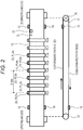
- Fig. 1 is a view illustrating a schematic configuration of a printing device 5 according to the embodiment of the present invention.
- the printing device 5 is an inkjet printer which discharges ink droplets from a print unit (print unit) PU to record an image on a recording medium 2 such as cloth.
- the printing device 5 is provided with a conveying unit which conveys the recording medium 2 by allowing an endless conveyor belt 13 stretched so as to surround a driving roller 11 and a driven roller 12 to go around, and the print unit PU as the printing unit which discharges ink to the recording medium 2 conveyed by the conveyor belt 13 to print the image; this discharges the ink from each print unit PU to the conveyed recording medium 2 to form (print) a desired image on the recording medium 2.
- print units PU1 to PU6 which print images in different colors are arranged along the conveyor belt 13 from an upstream side to a downstream side in a conveyance direction in which the conveyor belt 13 conveys the recording medium 2.
- up to eight print units PU may be mounted on the printing device 5.
- the number of print units PU is optional and is not limited to the above.
- the recording medium 2 in a roll shape or in a folded state is fed from an unwinding machine not illustrated to be supplied to an upstream end of the conveyor belt 13.
- pressing rollers 14 are provided to press the recording medium 2 against a belt surface of the conveyor belt 13 (refer to Fig. 1 ).
- the recording medium 2 is pressed against the belt surface of the conveyor belt 13 by the pressing rollers 14 and moves to be conveyed together with the conveyor belt 13.
- the recording medium 2 is separated from the conveyor belt 13 after passing through the pressing roller 14 on the downstream end side to be wound up by a winding machine not illustrated.
- the printing device 5 is a large device in which a perimeter of the conveyor belt 13 is about 28 m.
- work to set the conveyor belt 13 around the driving roller 11 and the driven roller 12 to adjust a length thereof, then weld ends in a longitudinal direction thereof to make the belt endless, and thereafter cut both ends in a width direction of the conveyor belt 13 into a necessary size is performed. Since cutting is performed at the site in this manner, the ends in the belt width direction of the conveyor belt 13 are not smooth but rough.
- the printing device 5 is provided with belt guides 15 and 16 applied from the side to right and left both ends of the conveyor belt 13 in order to prevent the conveyor belt 13 from deviating from the driving roller 11 and the driven roller 12 in the vicinity of the upstream end and downstream end, respectively, of the conveyor belt 13.
- the belt guides 15 and 16 are formed of metal plates or the like.
- the downstream side belt guide 15 is located slightly upstream of the driving roller 11 and abuts both the ends of the conveyor belt 13 on a forward path side from the driven roller 12 to the driving roller 11.
- the upstream side belt guide 16 is located slightly downstream of the driven roller 12 and abuts both the ends of the conveyor belt 13 on a backward path side from the driving roller 11 to the driven roller 12.
- a shape of the end of the conveyor belt 13 changes depending on application of the downstream side belt guide 15 and the upstream side belt guide 16, but this does not deform after passing the upstream side belt guide 16 until reaching the downstream side belt guide 15.
- the conveyor belt 13 is provided with an origin mark G indicating an origin of one round of the belt near one end.
- the origin mark G is a small-diameter hole provided on the conveyor belt 13.
- the origin mark G is not limited to a hole.
- An origin detection sensor 21 for detecting the origin mark G is provided slightly downstream of the most downstream print unit PU.
- Displacement sensors 23 which measure displacement amounts in the belt width direction orthogonal to the conveyance direction of the end of the conveyor belt 13 are provided on a plurality of measurement points separated in the conveyance direction of the conveyor belt 13. After the installation, positions of the measurement points and a distance between the measurement points are measured to be input to the printing device 5, so that the positions and distance are known to the printing device 5.
- the displacement sensors 23 are arranged in sites corresponding to the print units PU1 to PU6.
- the displacement sensor 23 is arranged in a position along the end of the conveyor belt 13 and at the center in the conveyance direction of the corresponding print unit PU.
- the displacement sensors 23 arranged in the positions corresponding to the respective print units PU1 to PU6 are referred to as displacement sensors PU1s to PU6s with s appended to the end of the reference sign PU of the print unit.
- the print units PU are arranged at regular intervals in the conveyance direction, and accordingly, the displacement sensors 23 (PU1s to PU6s) are also arranged at regular intervals in the conveyance direction. Out of the measurement points, the measurement point corresponding to the print unit PU1 is referred to as a reference point.
- the driving roller 11 is rotated by rotation of a motor transmitted through a transmission belt or the like.
- a rotary encoder 25 is attached to a shaft of the driving roller 11.
- the rotary encoder 25 is provided with a circular plate on an outer periphery of which a large number of slits are formed at equiangular intervals concentrically attached to the driving roller 11, and a detecting unit fixedly installed in the vicinity of the outer periphery of the circular plate for detecting passage of the slit of the rotating circular plate.
- the detecting unit outputs a pulse signal (A-phase signal and B-phase signal) every time this detects the passage of the slit.
- the rotary encoder 25 outputs, for example, 4096 A-phase pulse signals while the driving roller 11 rotates once. By counting the pulse signals, a moving amount (conveying distance) of the conveyor belt 13 may be recognized accurately and in real time. Note that the moving amount of the conveyor belt 13 may also be measured by a device other than the rotary encoder 25 such as a laser Doppler measuring instrument, for example.
- Fig. 3 illustrates an example of the displacement sensor 23.
- a transmissive laser displacement sensor is used as the displacement sensor 23.
- the displacement sensor 23 is mounted on a conveying machine side frame 27 extending along the end of the conveyor belt 13.
- the transmissive laser displacement sensor is provided with a light projecting unit 23a which emits a strip-shaped laser beam having a predetermined width collimated by a lens, and a light receiving unit 23b which receives the laser beam emitted from the light projecting unit 23a by a line CCD.
- the light receiving unit 23b is arranged so as to face the light projecting unit 23a at a predetermined distance from the light projecting unit 23a.
- Each displacement sensor (transmissive laser displacement sensor) 23 is installed along the end of the conveyor belt 13 such that the conveyor belt 13 blocks a part of the strip-shaped laser beam emitted from the light projecting unit 23a between the light projecting unit 23a and the light receiving unit 23b.
- the displacement sensor (transmissive laser displacement sensor) 23 detects a position of a shadow generated when the conveyor belt 13 blocks the laser beam by the light receiving unit 23b, thereby detecting the position of the end in the width direction of the conveyor belt 13.
- Fig. 4 is a view illustrating a front surface (nozzle surface) of a carriage 31 of the print unit PU.
- the carriage 31 is a frame member for holding a plurality of recording heads 32 in a correct positional relationship formed of a highly rigid metal plate or the like.
- a plurality of recording heads 32 which shares a printing range of one line in the width direction (main scanning direction) of the conveyor belt 13 is arranged in a staggered manner in the main scanning direction.
- Each recording head 32 discharges ink droplets from an ink discharge port 33 in response to an input drive signal.
- the print unit PU is a unit which incorporates the carriage 31 on which a plurality of recording heads 32 is mounted and a head driving circuit 43 to be described later.
- the displacement sensor 23 corresponding to the print unit PU it is preferable to arrange the same in a range within a thickness in the conveyance direction of the print unit PU, preferably the center position of the thickness. As illustrated in Fig. 4 , in a case where there is a plurality of nozzle rows in one print unit PU, this is desirably arranged in the center position of the plurality of nozzle rows. Note that if an interpolating process to be described later is performed, a meandering amount in an ideal center position may be estimated even if this is arranged in a position deviated from the ideal center position.
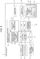
- Fig. 5 is a block diagram illustrating an electrical configuration of the printing device 5.
- the printing device 5 is provided with a conveyance control unit 41 which controls the conveyance by the conveying unit, a print data generating unit 42, the head driving circuit 43 in the print unit PU, a meandering correction control board 50 and the like.
- the conveyance control unit 41 controls the conveyance by the conveyor belt 13 by controlling driving of the motor which drives the driving roller 11.
- the print data generating unit 42 generates print data corresponding to an image to be printed by performing RIP processing or the like based on a print job received from an external device, and outputs the same to the head driving circuit 43 in the print unit PU.
- the head driving circuit 43 generates the driving signal according to the print data input from the print data generating unit 42, and outputs the same to the corresponding recording head 32.
- the meandering correction control board 50 fulfills a function of controlling measurement for detecting the meandering amount of the conveyor belt 13 and executing arithmetic operation thereof, and a function of outputting meandering information indicating the detected meandering amount to the head driving circuit 43 of each print unit PU.
- the meandering correction control board 50 includes a central processing unit (CPU) 51, a read only memory (ROM) 52, a random access memory (RAM) 53, a meandering information output unit 54, an I/O input unit 55, an encoder input unit 56, and an analog-to-digital converter (ADC) 57 and the like connected to a bus.
- CPU central processing unit
- ROM read only memory
- RAM random access memory
- ADC analog-to-digital converter
- a detection signal of the origin detection sensor 21 is input to the I/O input unit 55, and an output signal of the rotary encoder 25 is input to the encoder input unit 56. An output of each displacement sensor 23 is input to the ADC 57.
- the CPU 51 executes a program stored in the ROM 52, and the RAM 53 temporarily stores various data when the CPU 51 executes the program.
- the CPU 51 fulfills functions of a moving amount measuring unit 61, a displacement amount measuring unit 62, and a meandering amount arithmetic unit 63 by executing the program.
- the moving amount measuring unit 61 continuously measures the moving amount of the conveyor belt 13 in the conveyance direction.
- the moving amount (conveying distance) of the conveyor belt 13 from a time point at which the origin mark G reaches the origin detection sensor 21 is measured in real time. Since the moving amount per pulse is a fixed constant value of the device and is known, the moving amount (conveying distance) may be obtained accurately and in real time from a count value of the pulse signals output by the rotary encoder 25.
- the displacement amount measuring unit 62 fulfills a function of measuring the displacement amount in the belt width direction orthogonal to the conveyance direction of the end of the conveyor belt 13 by the displacement sensor 23 in one measurement point, and measuring the displacement amount in the same site as the site in which the displacement amount is measured by the displacement sensor 23 in one measurement point of the conveyor belt 13 by the displacement sensor 23 in another measurement point based on the moving amount measured by the moving amount measuring unit 61 and the known distance between the measurement points and recording the measurement data.
- the displacement amount measuring unit 62 measures the displacement amount at the time when the pulse signal is output by each displacement sensor 23, and associates the displacement amount measured by each displacement sensor 23 with the moving amount (conveying distance) of the conveyor belt at that time measured by the moving amount measuring unit 61 to record in the RAM 53.
- an integral multiple of the conveying distance in a measuring cycle of the displaced amount (in this example, the conveying distance per pulse of the rotary encoder 25) is set to be the distance between the measurement points.
- the same site in the conveyance direction of the conveyor belt 13 is measured by the displacement sensors 23 in the respective measurement point.
- the measuring cycle of the displacement amount may be optional as long as the integral multiple of the conveying distance in the measuring cycle may be the distance between the measurement points.
- the conveying distance corresponding to a pixel pitch in the conveyance direction may be made the measuring cycle.
- the meandering amount arithmetic unit 63 performs arithmetic operation of obtaining the meandering amount of the conveyor belt 13 in another measurement point with respect to one measurement point by taking a difference between the displacement amounts in the same site measured to be recorded in one measurement point and another measurement point by the displacement amount measuring units 62.
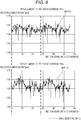
- FIG. 6 illustrates an example of measurement data recorded by the displacement amount measuring unit 62.
- a graph A on an upper side in the drawing is a graph of the measurement data in which the displacement amount measured by the displacement sensor 23 (PU1s) arranged in the position corresponding to the print unit PU1 and the moving amount (conveying distance) of the conveyor belt 13 after the origin detection sensor 21 detects the origin mark G are recorded in association with each other.
- the displacement amount is plotted along the ordinate, and the moving amount (conveying distance) after the origin mark G is detected is plotted along the abscissa.
- a graph B on a lower side in the drawing is a graph corresponding the measurement data in which the displacement amount measured by the displacement sensor 23 (PU4s) arranged in the position corresponding to the print unit PU4 and the moving amount (conveying distance) of the conveyor belt 13 after the origin detection sensor 21 detects the origin mark G are recorded in association with each other.
- the meandering amount of the conveyor belt 13 in the position of the displacement sensor PU1s (position of the print unit PU1) with respect to the position of the displacement sensor PU4s (position of the print unit PU4) is obtained by offsetting the measurement data measured by the displacement sensor PU4s by 3.14 m (entirely offset the graph B to the left by 3.14 m) and subtracting the measurement data of the displacement sensor PU1s from the offset measurement data of the displacement sensor PU4s.
- Fig. 7 illustrates a graph C representing a difference between the graph B offset to the left by 3.14 m and the graph A.
- the graph C represents a relationship between the moving amount (conveying distance) of the conveyor belt 13 from the time point at which the origin mark G is detected by the origin detection sensor 21 and the meandering amount of the conveyor belt 13 in the position of the displacement sensor PU1s with respect to the position of the displacement sensor PU4s.
- the meandering correction control board 50 outputs data obtained by applying a low-pass filter to data of a difference value to remove spike-like noise (noise caused by fluff of the end of the conveyor belt 13, vertical oscillation of the conveyor belt 13, vibration and the like) to the head driving circuit 43 of the corresponding print unit PU as the meandering information.
- the meandering amount is rounded to a level of the pixel pitch in the main scanning direction by applying the low-pass filter. Note that a reason for which this is rounded to the level of the pixel pitch is that correction of a printing position by a print control unit 43a to be described later cannot be made finer than the pixel pitch in the main scanning direction.
- the print control unit 43a (refer to Fig. 5 ) of the head driving circuit 43 of each print unit PU changes the printing position of the image in the width direction (main scanning direction) of the conveyor belt 13 such that the meandering amount in the position of the print unit PU (meandering amount with respect to the reference point) is canceled out based on the meandering information input from the meandering correction control board 45.
- the reference point is in the position of the print unit PU4 and the meandering amount in the position of the print unit PU1 with respect to the reference point in a predetermined site of the conveyor belt is a distance of three pixels to a left end side of the conveyor belt 13, an image of a line to be printed when the predetermined site of the conveyor belt reaches the position of the print unit PU1 is shifted by three pixels to the left end side of the conveyor belt 13 to be printed.
- the meandering correction control board 50 outputs the meandering information obtained by the measurement of the previous cycle to the print control unit 43a of the head driving circuit 43, and the print control unit 43a corrects the printing position based on the meandering information of the previous cycle.
- the reference point By using the meandering information of the previous cycle, it is possible to set the reference point in an arbitrary position such as the center position in the conveyance direction as the position corresponding to the print unit PU4. For example, even in a case where the meandering of the conveyor belt 13 is monotonically shifted to one side from upstream to downstream, it is possible to divide the correction of the printing position in positive and negative both directions by setting the reference point in the center position in the conveyance direction such as the position of the print unit PU4, so that it is possible to correct to cancel out the meandering amount by a small correction amount regardless of the end side to which the conveyor belt meanders as compared with a case where the reference point is set in the position of the uppermost or lowermost print unit PU.
- a case where the meandering amount of the conveyor belt 13 in the position of the displacement sensor PU1s with respect to the position of the displacement sensor PU4s is obtained is taken as an example. It is assumed that the displacement sensor PU1s is in the position of the print unit PU1 and the displacement sensor PU4s is in the position of the print unit PU4.
- Fig. 8 addresses 0 to 13 are assigned to start point positions of the respective sections obtained by dividing the conveyor belt 13 into 14 starting from the position of the origin mark G.
- Figs. 9 to 11 illustrate a measurement status in time series.
- the measurement is started at a timing at which the origin detection sensor 21 detects the origin mark G as starting reference time of the measurement by each displacement sensor 23 (PU1s and PU4s) (Q1 in Fig. 9 ).
- Each graph in Figs. 9 to 11 represents the belt end position (displacement amount) measured by the displacement sensor 23 (PUIs), the belt end position (displacement amount) measured by the displacement sensor 23 (PU4s), and the belt meandering amount in the PU1s position with respect to the PU4s position.
- the belt end position (displacement amount) or meandering amount is plotted along the ordinate, the position on the conveyor belt on which the position of the origin mark G is 0 is plotted along the abscissa, and numerical values along the abscissa correspond to the addresses assigned when the perimeter is divided into 14.
- the positional relationship between the origin detection sensor 21 and each displacement sensor 23 (PU1s and PU4s) is known, it is possible to grasp the position on the conveyor belt 13 measured by the displacement sensors PU1s and PU4s at the timing at which the origin detection sensor 21 detects the origin mark G. For example, when the measurement is started, the displacement sensor PU1s is in the position of the fifth address and the displacement sensor PU4s is in the position of the third address.
- Fig. 9 (Q2) illustrates the measurement status at a timing at which it is conveyed by one section from the start of the measurement.
- the displacement sensor PU1s measures the belt end position (displacement amount) from the fifth to sixth addresses of the conveyor belt 13, and the displacement sensor PU4s measures the belt end position (displacement amount) from the third to fourth addresses.
- Fig. 9 (Q3) illustrates the measurement status at a timing at which it is conveyed by two sections from the start of the measurement.
- the displacement sensor PU1s measures the belt end position (displacement amount) from the fifth to seventh addresses from the start of the measurement, and the displacement sensor PU4s measures the belt end position (displacement amount) from the third to fifth addresses.
- Fig. 10 (Q4) illustrates the measurement status at a timing at which it is conveyed by three sections from the start of the measurement and the meandering amount of an arithmetic result.
- the measurement data in the same site are prepared, so that the meandering amount is calculated by taking the difference between the measurement data of the displacement sensor PU1s and the measurement data of the displacement sensor PU4s.
- Fig. 10 (Q5) illustrates the measurement status at a timing at which it is conveyed by 13 sections from the start of the measurement and the meandering amount of the arithmetic result.
- Fig. 10 (Q6) illustrates the measurement status at a timing at which it is conveyed by 14 sections from the start of the measurement (to come full circle) and the meandering amount of the arithmetic result.
- the head driving circuit 43 of the print unit PU1 Based on the meandering information received from the meandering correction control board 50, the head driving circuit 43 of the print unit PU1 performs printing while shifting the image in the main scanning direction so as to cancel out the meandering amount.
- the measurement data of the displacement sensor PU4s is the data of the second cycle
- the measurement data of the displacement sensor PU1s is the data of previous cycle. Since the belt end does not come into contact with the belt guides 15 and 16 in a section between the upstream side belt guide 16 and the downstream side belt guide 15, the shape of the belt end is considered not to change if the data is of the same cycle; however, in different cycles, the shape of the belt end might change due to contact with the upstream side belt guide 16 or the like. Therefore, it is desirable that the measurement values the difference between which is taken be the measurement values of the same cycle.
- the data of the two cycles are maintained and updated to the latest data sequentially, and the difference between the measurement data of the same cycle is taken to obtain the meandering amount. Further, it is preferable to start actual printing after moving the conveyor belt 13 by two or more cycles before printing to make it possible to obtain the meandering amount by the measurement values of the same cycle in all the belt positions.
- Fig. 12 is a flowchart illustrating a process in which the printing device 5 corrects the meandering amount to print.
- the meandering amount of the conveyor belt 13 in the PU1s position with respect to the PU4s position is obtained to correct the image data as in Figs. 9 to 11 is illustrated.
- the displacement sensor PU1s is in the position of the print unit PU1 and the displacement sensor PU4s is in the position of the print unit PU4. Note that a similar process is actually performed for all the print units PU1 to PU6 (other than PU4 when PU4 is used as a reference point).
- step S101 the conveyor belt 13 is driven to start the conveyance (step S101). If the conveyance (printing) is not finished (step S102; No), it is checked whether the origin detection sensor 21 detects the origin mark G (step S103). If the conveyance (printing) is finished (step S102; Yes), this procedure is finished.
- step S103 When the origin mark G is detected (step S103; Yes), the position on the belt (position in the conveyance direction with respect to the origin mark G) measured by the displacement sensors PU1s and PU4s is reset based on the known positional relationship among the origin detection sensor 21 and the displacement sensors PU1s and PU4 (step S104), the number of times of origin detection is incremented by one (step S105), and the procedure shifts to step S107.
- step S103 the position on the belt (position in the conveyance direction with respect to the origin mark G) measured by the displacement sensors PU1s and PU4s is updated by adding the conveying distance from when the origin detection sensor 21 detects the origin mark G (distance obtained by counting the output pulses of the rotary encoder 25 from when the origin mark G is detected) (step S106) and the procedure shifts to step S107.
- step S107 the belt end position (displacement amount) detected by the displacement sensor PU1s and the position on the belt of the displacement sensor PU1s are stored in association with each other, and the belt end position (displacement amount) detected by the displacement sensor PU4s and the position on the belt of the displacement sensor PU4s are stored in association with each other.
- step S108 it is checked whether or not the number of times of origin detection is smaller than a predetermined value (for example, two or three), and if this is smaller than the predetermined value (step S108; No), the procedure returns to step S102 to be continued.
- a predetermined value for example, two or three
- step S108 If the number of times of origin detection is equal to or larger than the predetermined value (step S108; Yes), the difference between the measurement values (belt end positions (displacement amounts)) of the displacement sensors PU1s and PU4s of the previous cycle corresponding to a current belt position of the displacement sensor PU1s is taken, and the belt meandering amount in the PU1s position with respect to the PU4s position is calculated (step S109). Furthermore, a low-pass filter is applied to the belt meandering amount (step S110), and the obtained meandering amount is output to the head driving circuit 43 of the print unit PU1 to be fed back (step S111).
- step S112 If the printing is in progress (step S112; Yes), the head driving circuit 43 shifts the image data in the main scanning direction (belt width direction) so that the meandering amount is canceled out (step S113), and allows each recording head 32 to discharge the ink according to the shifted image data to print the image on the recording medium 2 (step S114), then returns to step S102 to continue the procedure.
- the head driving circuit 43 shifts the image data in the main scanning direction (belt width direction) so that the meandering amount is canceled out (step S113), and allows each recording head 32 to discharge the ink according to the shifted image data to print the image on the recording medium 2 (step S114), then returns to step S102 to continue the procedure.
- step S112 If the printing is not in progress (step S112; No), the procedure returns to step S102 to be continued without executing steps S113 and S114.
- the meandering amount in a position other than the measurement point where the displacement sensor 23 is arranged is estimated by an interpolating processing based on the meandering amount in a plurality of measurement points. For example, in a case where the displacement sensor 23 cannot be installed in the center position in the conveyance direction (ideal position) of each print unit PU due to mechanical constraints, the displacement sensor 23 is located in a position different from the ideal position (preferably close to the ideal position as much as possible), and the meandering amount in the ideal position is obtained by an interpolating process based on the meandering amounts measured by a plurality of displacement sensors 23.
- each displacement sensor 23 has the same deviation from the ideal position.
- the same interpolating process may be performed, so that the interpolating process becomes easy as a whole.
- a distance from the reference point to a first measurement point is set to L1
- a distance from the reference point to a second measurement point is set to L2
- a distance from the reference point to a predetermined print unit PU is set to L3 (L1 ⁇ L3 ⁇ L2)
- a meandering amount in the first measurement point and a meandering amount in the second measurement point regarding the same site of the conveyor belt 13 are set to D1 and D2, respectively.
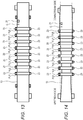
- the displacement sensors 23 may be arranged along both ends of the conveyor belt 13.
- the belt In a case where the perimeter of the conveyor belt 13 is long, the belt not only meanders but also expands and contracts in the width direction as illustrated in Fig. 14 , so that the ink landing position in the belt width direction (main scanning direction) might be displaced from a target position. If the displacement sensors 23 are arranged on the right and left both ends of the conveyor belt 13, it is possible to detect and correct also the change in the expansion and contraction of the conveyor belt 13 in the width direction.
- the meandering amount in the PU1s position with respect to the PU4s position is +0.05 mm on the right end and +0.03 mm on the left end, an average of +0.04 is corrected as the meandering amount.
- the inkjet printer is exemplified as the printing device 5, but an LED printer or the like may be used as long as the recording medium 2 is conveyed by the conveyor belt 13.
Landscapes
- Engineering & Computer Science (AREA)
- Textile Engineering (AREA)
- Ink Jet (AREA)
- Controlling Sheets Or Webs (AREA)
- Handling Of Sheets (AREA)
- Control Or Security For Electrophotography (AREA)
- Color Electrophotography (AREA)
Abstract
To provide a printing device (5) and a meandering amount detecting method capable of correctly detecting a meandering amount of a conveyor belt (13) having irregularities on an end even if a conveying speed is changed and cope with the same.
Displacement sensors (23) arranged in a plurality of measurement points separated in a conveyance direction measures displacement amounts in a belt width direction of an end position of a conveyor belt (13) while calculating pulses of a rotary encoder (25) and measuring a moving amount of the conveyor belt (13). At that time, the displacement amounts in the same site of the conveyor belt (13) are measured in respective measurement points from the measured moving amount and a known distance between the measurement points. Then, by taking a difference between the displacement amounts in the same site measured in one measurement point and another measurement point, a meandering amount of the conveyor belt (13) in another measurement point with respect to one measurement point is obtained, and a printing position of the image is shifted in each of printing heads (PU1 to PU6) such that the measuring amount is canceled out.
Description
- The present invention relates to a printing device and a meandering amount detecting method for forming an image on a recording medium conveyed by a conveyor belt.
- There is a color inkjet printer as an example of a printing device which conveys a recording medium by an endless conveyor belt stretched around a plurality of rollers to go around and forms an image on the conveyed recording medium. In the color inkjet printer, a plurality of print head units of different colors is arranged at predetermined intervals in a conveyance direction of the conveyor belt, and ink droplets of different colors discharged from the respective print units are overlapped on the recording medium conveyed by the conveyor belt, so that a color image is formed.
- In such printing device, when the conveyor belt which conveys the recording medium meanders in a direction orthogonal to the conveyance direction of the conveyor belt (belt width direction), a landing position of each color ink droplet on the recording medium is displaced from an original position and color deviation occurs.
- As a method to cope with this problem, a control is performed in which an end position in the width direction of the conveyor belt is measured by a sensor, fluctuation in measured value is regarded as a meandering amount, and a printing position of the image is shifted so that the meandering amount is cancelled out.
- However, if the end of the conveyor belt is rough and irregular, the variation in the end position measured by the sensor includes an effect of roughness of the belt end, and it is not possible to correctly measure the meandering amount to correct.
- For example, in an inkjet textile printer which conveys cloth, a large conveying machine in which a perimeter of a conveyor belt is over 20 m is used, so that the conveying machine is assembled at an installation site in general. In detail, at the installation site, work to set the conveyor belt around conveying rollers to adjust a length thereof, then weld ends in a longitudinal direction thereof to make the belt endless, and thereafter cut both ends in a width direction of the conveyor belt so as to fit a size of the conveying rollers is performed. A belt guide formed of a metal plate and the like is applied to both sides in the width direction of the conveyor belt so that the conveyor belt does not meander beyond a certain range to deviate from the conveying roller.
- Due to cutting at the installation site described above, the end of the conveyor belt is not smooth but "rough". Since the roughness of the end of the conveyor belt and a meandering state thereof gradually change due to the application of the belt guide, it is difficult to cope with the same based on a profile.
-
JP 2007-114240 A - In the device disclosed in
JP 2007-114240 A - For example, in the above-described inkjet textile printer, a conveying speed might be changed significantly during printing by user operation while checking a printing result and a cloth state (whether or not this is bent) or checking a status of an unwinding machine, a winding machine, and a drying machine. Therefore, the method of
JP 2007-114240 A - The present invention is intended to solve the above-described problem, and an object thereof is to provide a printing device and a meandering amount detecting method capable of correctly detecting a meandering amount of a conveyor belt having irregularities on an end even if a conveying speed is changed and cope with the same.
- To achieve the abovementioned object, according to an aspect of the present invention, a printing device reflecting one aspect of the present invention comprises: a conveying unit which allows an endless conveyor belt stretched around a plurality of rollers to go around to convey a recording medium; a printing unit which forms an image on a recording medium conveyed by the conveying unit; a moving amount measuring unit which measures a moving amount in a conveyance direction of the conveyor belt; a plurality of displacement sensors arranged in a plurality of measurement points separated in the conveyance direction of the conveyor belt which measures displacement amounts in a belt end direction orthogonal to the conveyance direction of an end of the conveyor belt; a displacement amount measuring unit which measures the displacement amounts in the same site of the conveyor belt by a displacement sensor in one measurement point and a displacement sensor in another measurement point based on the moving amount measured by the moving amount measuring unit and a known distance between the measuring points; and a meandering amount arithmetic unit which obtains a meandering amount of the conveyor belt in the other measurement point with respect to the one measurement point by taking a difference between the displacement amounts in the same site measured by the displacement amount measuring unit in the one measurement point and the other measurement point.
- The advantages and features provided by one or more embodiments of the invention will become more fully understood from the detailed description given hereinbelow and the appended drawings which are given by way of illustration only, and thus are not intended as a definition of the limits of the present invention:
-
Fig. 1 is a view illustrating a schematic configuration of a printing device according to an embodiment of the present invention; -
Fig. 2 is a plan view of the printing device and a side view of a belt portion according to the embodiment of the present invention; -
Fig. 3 is a view illustrating a displacement sensor and a mounting state thereof; -
Fig. 4 is a view illustrating a nozzle surface of a carriage of a print unit; -
Fig. 5 is a block diagram illustrating an electrical configuration of the printing device; -
Fig. 6 is a view illustrating an example of displacement amount data measured in a PU1s position and a PU4s position; -
Fig. 7 is a view illustrating an example of a belt meandering amount in the PU1s position with respect to the PU4s position; -
Fig. 8 is a view illustrating a positional relationship between an origin detection sensor and displacement sensors PU1s and PU4s, and addresses assigned to respective sections obtained by dividing a perimeter of the conveyor belt; -
Fig. 9 is a view illustrating a measuring process of the meandering amount in time series; -
Fig. 10 is a view illustrating subsequent steps ofFig. 9 ; -
Fig. 11 is a view illustrating subsequent steps ofFig. 10 ; -
Fig. 12 is a flowchart illustrating a process in which the printing device obtains the meandering amount and performs printing while correcting the meandering amount; -
Fig. 13 is a plan view illustrating a conveying unit of the printing device in which displacement sensors are arranged along right and left both ends of the conveyor belt; and -
Fig. 14 is an explanatory view illustrating a state in which the conveyor belt expands and contracts in a width direction. - Hereinafter, one or more embodiments of the present invention will be described with reference to the drawings. However, the scope of the invention is not limited to the disclosed embodiments.
-
Fig. 1 is a view illustrating a schematic configuration of aprinting device 5 according to the embodiment of the present invention. Theprinting device 5 is an inkjet printer which discharges ink droplets from a print unit (print unit) PU to record an image on arecording medium 2 such as cloth. Theprinting device 5 is provided with a conveying unit which conveys therecording medium 2 by allowing anendless conveyor belt 13 stretched so as to surround adriving roller 11 and a drivenroller 12 to go around, and the print unit PU as the printing unit which discharges ink to therecording medium 2 conveyed by theconveyor belt 13 to print the image; this discharges the ink from each print unit PU to the conveyedrecording medium 2 to form (print) a desired image on therecording medium 2. - In the
printing device 5 illustrated inFig. 1 , six print units PU1 to PU6 which print images in different colors are arranged along theconveyor belt 13 from an upstream side to a downstream side in a conveyance direction in which theconveyor belt 13 conveys therecording medium 2. Note that, as illustrated inFig. 2 , up to eight print units PU may be mounted on theprinting device 5. Note that, the number of print units PU is optional and is not limited to the above. - The
recording medium 2 in a roll shape or in a folded state is fed from an unwinding machine not illustrated to be supplied to an upstream end of theconveyor belt 13. At the upstream end and a downstream end of theconveyor belt 13, pressingrollers 14 are provided to press therecording medium 2 against a belt surface of the conveyor belt 13 (refer toFig. 1 ). Therecording medium 2 is pressed against the belt surface of theconveyor belt 13 by thepressing rollers 14 and moves to be conveyed together with theconveyor belt 13. Therecording medium 2 is separated from theconveyor belt 13 after passing through thepressing roller 14 on the downstream end side to be wound up by a winding machine not illustrated. - The
printing device 5 is a large device in which a perimeter of theconveyor belt 13 is about 28 m. At an installation site, work to set theconveyor belt 13 around thedriving roller 11 and the drivenroller 12 to adjust a length thereof, then weld ends in a longitudinal direction thereof to make the belt endless, and thereafter cut both ends in a width direction of theconveyor belt 13 into a necessary size is performed. Since cutting is performed at the site in this manner, the ends in the belt width direction of theconveyor belt 13 are not smooth but rough. - The
printing device 5 is provided withbelt guides conveyor belt 13 in order to prevent theconveyor belt 13 from deviating from thedriving roller 11 and the drivenroller 12 in the vicinity of the upstream end and downstream end, respectively, of theconveyor belt 13. Thebelt guides side belt guide 15 is located slightly upstream of thedriving roller 11 and abuts both the ends of theconveyor belt 13 on a forward path side from the drivenroller 12 to thedriving roller 11. The upstreamside belt guide 16 is located slightly downstream of the drivenroller 12 and abuts both the ends of theconveyor belt 13 on a backward path side from thedriving roller 11 to the drivenroller 12. - A shape of the end of the
conveyor belt 13 changes depending on application of the downstreamside belt guide 15 and the upstreamside belt guide 16, but this does not deform after passing the upstreamside belt guide 16 until reaching the downstreamside belt guide 15. - The
conveyor belt 13 is provided with an origin mark G indicating an origin of one round of the belt near one end. Herein, the origin mark G is a small-diameter hole provided on theconveyor belt 13. The origin mark G is not limited to a hole. Anorigin detection sensor 21 for detecting the origin mark G is provided slightly downstream of the most downstream print unit PU. -
Displacement sensors 23 which measure displacement amounts in the belt width direction orthogonal to the conveyance direction of the end of theconveyor belt 13 are provided on a plurality of measurement points separated in the conveyance direction of theconveyor belt 13. After the installation, positions of the measurement points and a distance between the measurement points are measured to be input to theprinting device 5, so that the positions and distance are known to theprinting device 5. - Herein, the
displacement sensors 23 are arranged in sites corresponding to the print units PU1 to PU6. In detail, thedisplacement sensor 23 is arranged in a position along the end of theconveyor belt 13 and at the center in the conveyance direction of the corresponding print unit PU. Hereinafter, thedisplacement sensors 23 arranged in the positions corresponding to the respective print units PU1 to PU6 are referred to as displacement sensors PU1s to PU6s with s appended to the end of the reference sign PU of the print unit. - Note that the print units PU are arranged at regular intervals in the conveyance direction, and accordingly, the displacement sensors 23 (PU1s to PU6s) are also arranged at regular intervals in the conveyance direction. Out of the measurement points, the measurement point corresponding to the print unit PU1 is referred to as a reference point.
- The driving
roller 11 is rotated by rotation of a motor transmitted through a transmission belt or the like. Arotary encoder 25 is attached to a shaft of the drivingroller 11. - The
rotary encoder 25 is provided with a circular plate on an outer periphery of which a large number of slits are formed at equiangular intervals concentrically attached to the drivingroller 11, and a detecting unit fixedly installed in the vicinity of the outer periphery of the circular plate for detecting passage of the slit of the rotating circular plate. The detecting unit outputs a pulse signal (A-phase signal and B-phase signal) every time this detects the passage of the slit. Therotary encoder 25 outputs, for example, 4096 A-phase pulse signals while the drivingroller 11 rotates once. By counting the pulse signals, a moving amount (conveying distance) of theconveyor belt 13 may be recognized accurately and in real time. Note that the moving amount of theconveyor belt 13 may also be measured by a device other than therotary encoder 25 such as a laser Doppler measuring instrument, for example. -
Fig. 3 illustrates an example of thedisplacement sensor 23. Herein, a transmissive laser displacement sensor is used as thedisplacement sensor 23. Thedisplacement sensor 23 is mounted on a conveyingmachine side frame 27 extending along the end of theconveyor belt 13. - The transmissive laser displacement sensor is provided with a
light projecting unit 23a which emits a strip-shaped laser beam having a predetermined width collimated by a lens, and alight receiving unit 23b which receives the laser beam emitted from thelight projecting unit 23a by a line CCD. Thelight receiving unit 23b is arranged so as to face thelight projecting unit 23a at a predetermined distance from thelight projecting unit 23a. Each displacement sensor (transmissive laser displacement sensor) 23 is installed along the end of theconveyor belt 13 such that theconveyor belt 13 blocks a part of the strip-shaped laser beam emitted from thelight projecting unit 23a between the light projectingunit 23a and thelight receiving unit 23b. The displacement sensor (transmissive laser displacement sensor) 23 detects a position of a shadow generated when theconveyor belt 13 blocks the laser beam by thelight receiving unit 23b, thereby detecting the position of the end in the width direction of theconveyor belt 13. -
Fig. 4 is a view illustrating a front surface (nozzle surface) of acarriage 31 of the print unit PU. Thecarriage 31 is a frame member for holding a plurality of recording heads 32 in a correct positional relationship formed of a highly rigid metal plate or the like. On thecarriage 31, a plurality of recording heads 32 which shares a printing range of one line in the width direction (main scanning direction) of theconveyor belt 13 is arranged in a staggered manner in the main scanning direction. Eachrecording head 32 discharges ink droplets from anink discharge port 33 in response to an input drive signal. Note that the print unit PU is a unit which incorporates thecarriage 31 on which a plurality of recording heads 32 is mounted and ahead driving circuit 43 to be described later. - In a case of arranging the
displacement sensor 23 corresponding to the print unit PU, it is preferable to arrange the same in a range within a thickness in the conveyance direction of the print unit PU, preferably the center position of the thickness. As illustrated inFig. 4 , in a case where there is a plurality of nozzle rows in one print unit PU, this is desirably arranged in the center position of the plurality of nozzle rows. Note that if an interpolating process to be described later is performed, a meandering amount in an ideal center position may be estimated even if this is arranged in a position deviated from the ideal center position. -
Fig. 5 is a block diagram illustrating an electrical configuration of theprinting device 5. Theprinting device 5 is provided with aconveyance control unit 41 which controls the conveyance by the conveying unit, a printdata generating unit 42, thehead driving circuit 43 in the print unit PU, a meanderingcorrection control board 50 and the like. - The
conveyance control unit 41 controls the conveyance by theconveyor belt 13 by controlling driving of the motor which drives the drivingroller 11. The printdata generating unit 42 generates print data corresponding to an image to be printed by performing RIP processing or the like based on a print job received from an external device, and outputs the same to thehead driving circuit 43 in the print unit PU. Thehead driving circuit 43 generates the driving signal according to the print data input from the printdata generating unit 42, and outputs the same to thecorresponding recording head 32. - The meandering
correction control board 50 fulfills a function of controlling measurement for detecting the meandering amount of theconveyor belt 13 and executing arithmetic operation thereof, and a function of outputting meandering information indicating the detected meandering amount to thehead driving circuit 43 of each print unit PU. - The meandering
correction control board 50 includes a central processing unit (CPU) 51, a read only memory (ROM) 52, a random access memory (RAM) 53, a meanderinginformation output unit 54, an I/O input unit 55, anencoder input unit 56, and an analog-to-digital converter (ADC) 57 and the like connected to a bus. - A detection signal of the
origin detection sensor 21 is input to the I/O input unit 55, and an output signal of therotary encoder 25 is input to theencoder input unit 56. An output of eachdisplacement sensor 23 is input to theADC 57. - The
CPU 51 executes a program stored in theROM 52, and theRAM 53 temporarily stores various data when theCPU 51 executes the program. TheCPU 51 fulfills functions of a movingamount measuring unit 61, a displacementamount measuring unit 62, and a meandering amountarithmetic unit 63 by executing the program. - The moving
amount measuring unit 61 continuously measures the moving amount of theconveyor belt 13 in the conveyance direction. Herein, by counting the pulse signals output by therotary encoder 25 based on a time point at which theorigin detection sensor 21 detects the origin mark G, the moving amount (conveying distance) of theconveyor belt 13 from a time point at which the origin mark G reaches theorigin detection sensor 21 is measured in real time. Since the moving amount per pulse is a fixed constant value of the device and is known, the moving amount (conveying distance) may be obtained accurately and in real time from a count value of the pulse signals output by therotary encoder 25. - The displacement
amount measuring unit 62 fulfills a function of measuring the displacement amount in the belt width direction orthogonal to the conveyance direction of the end of theconveyor belt 13 by thedisplacement sensor 23 in one measurement point, and measuring the displacement amount in the same site as the site in which the displacement amount is measured by thedisplacement sensor 23 in one measurement point of theconveyor belt 13 by thedisplacement sensor 23 in another measurement point based on the moving amount measured by the movingamount measuring unit 61 and the known distance between the measurement points and recording the measurement data. - For example, for each pulse signal output by the
rotary encoder 25, the displacementamount measuring unit 62 measures the displacement amount at the time when the pulse signal is output by eachdisplacement sensor 23, and associates the displacement amount measured by eachdisplacement sensor 23 with the moving amount (conveying distance) of the conveyor belt at that time measured by the movingamount measuring unit 61 to record in theRAM 53. - Note that an integral multiple of the conveying distance in a measuring cycle of the displaced amount (in this example, the conveying distance per pulse of the rotary encoder 25) is set to be the distance between the measurement points. As a result, the same site in the conveyance direction of the
conveyor belt 13 is measured by thedisplacement sensors 23 in the respective measurement point. - The measuring cycle of the displacement amount may be optional as long as the integral multiple of the conveying distance in the measuring cycle may be the distance between the measurement points. For example, the conveying distance corresponding to a pixel pitch in the conveyance direction may be made the measuring cycle.
- The meandering amount
arithmetic unit 63 performs arithmetic operation of obtaining the meandering amount of theconveyor belt 13 in another measurement point with respect to one measurement point by taking a difference between the displacement amounts in the same site measured to be recorded in one measurement point and another measurement point by the displacementamount measuring units 62. -
Fig. 6 illustrates an example of measurement data recorded by the displacementamount measuring unit 62. A graph A on an upper side in the drawing is a graph of the measurement data in which the displacement amount measured by the displacement sensor 23 (PU1s) arranged in the position corresponding to the print unit PU1 and the moving amount (conveying distance) of theconveyor belt 13 after theorigin detection sensor 21 detects the origin mark G are recorded in association with each other. The displacement amount is plotted along the ordinate, and the moving amount (conveying distance) after the origin mark G is detected is plotted along the abscissa. A graph B on a lower side in the drawing is a graph corresponding the measurement data in which the displacement amount measured by the displacement sensor 23 (PU4s) arranged in the position corresponding to the print unit PU4 and the moving amount (conveying distance) of theconveyor belt 13 after theorigin detection sensor 21 detects the origin mark G are recorded in association with each other. - For example, if the reference point is in the position of the displacement sensor PU4s and the measurement point is in the position of the displacement sensor PU1s located upstream of the reference point by 3.14 m, the meandering amount of the
conveyor belt 13 in the position of the displacement sensor PU1s (position of the print unit PU1) with respect to the position of the displacement sensor PU4s (position of the print unit PU4) is obtained by offsetting the measurement data measured by the displacement sensor PU4s by 3.14 m (entirely offset the graph B to the left by 3.14 m) and subtracting the measurement data of the displacement sensor PU1s from the offset measurement data of the displacement sensor PU4s. - Note that by removing a DC component from the output signal of the
displacement sensor 23, a displacement amount component of the end of theconveyor belt 13 may be extracted regardless of an absolute position of thedisplacement sensor 23. Therefore, it is not necessary to accurately arrange relative mounting positions of the plurality ofdisplacement sensors 23 on a straight line. -
Fig. 7 illustrates a graph C representing a difference between the graph B offset to the left by 3.14 m and the graph A. The graph C represents a relationship between the moving amount (conveying distance) of theconveyor belt 13 from the time point at which the origin mark G is detected by theorigin detection sensor 21 and the meandering amount of theconveyor belt 13 in the position of the displacement sensor PU1s with respect to the position of the displacement sensor PU4s. - Note that the meandering
correction control board 50 outputs data obtained by applying a low-pass filter to data of a difference value to remove spike-like noise (noise caused by fluff of the end of theconveyor belt 13, vertical oscillation of theconveyor belt 13, vibration and the like) to thehead driving circuit 43 of the corresponding print unit PU as the meandering information. Herein, the meandering amount is rounded to a level of the pixel pitch in the main scanning direction by applying the low-pass filter. Note that a reason for which this is rounded to the level of the pixel pitch is that correction of a printing position by aprint control unit 43a to be described later cannot be made finer than the pixel pitch in the main scanning direction. - The
print control unit 43a (refer toFig. 5 ) of thehead driving circuit 43 of each print unit PU changes the printing position of the image in the width direction (main scanning direction) of theconveyor belt 13 such that the meandering amount in the position of the print unit PU (meandering amount with respect to the reference point) is canceled out based on the meandering information input from the meanderingcorrection control board 45. For example, if the reference point is in the position of the print unit PU4 and the meandering amount in the position of the print unit PU1 with respect to the reference point in a predetermined site of the conveyor belt is a distance of three pixels to a left end side of theconveyor belt 13, an image of a line to be printed when the predetermined site of the conveyor belt reaches the position of the print unit PU1 is shifted by three pixels to the left end side of theconveyor belt 13 to be printed. - Note that, in the meandering of the
conveyor belt 13, substantially similar change is repeated with one round of theconveyor belt 13 as a cycle. The meandering amount changes gradually due to fluctuation in temperature and application of the end of theconveyor belt 13 to the downstreamside belt guide 15 or the upstreamside belt guide 16, but this changes gradually and is almost unchanged from the previous cycle. - In contrast, it is difficult to perform control to measure the displacement amount of the end of the
conveyor belt 13 by thedisplacement sensor 23 installed in the position of the print unit PU, calculate the meandering amount, and shift the printing position based on this in real time. - Therefore, in this embodiment, the meandering
correction control board 50 outputs the meandering information obtained by the measurement of the previous cycle to theprint control unit 43a of thehead driving circuit 43, and theprint control unit 43a corrects the printing position based on the meandering information of the previous cycle. By using the meandering information of the previous cycle in this manner, it is possible to perform control to calculate the meandering amount and shift the printing position in plenty of time. - By using the meandering information of the previous cycle, it is possible to set the reference point in an arbitrary position such as the center position in the conveyance direction as the position corresponding to the print unit PU4. For example, even in a case where the meandering of the
conveyor belt 13 is monotonically shifted to one side from upstream to downstream, it is possible to divide the correction of the printing position in positive and negative both directions by setting the reference point in the center position in the conveyance direction such as the position of the print unit PU4, so that it is possible to correct to cancel out the meandering amount by a small correction amount regardless of the end side to which the conveyor belt meanders as compared with a case where the reference point is set in the position of the uppermost or lowermost print unit PU. - Next, a process of calculating the meandering amount is described more specifically.
- Herein, a case where the meandering amount of the
conveyor belt 13 in the position of the displacement sensor PU1s with respect to the position of the displacement sensor PU4s is obtained is taken as an example. It is assumed that the displacement sensor PU1s is in the position of the print unit PU1 and the displacement sensor PU4s is in the position of the print unit PU4. - In this example, it is assumed that the perimeter of the
conveyor belt 13 is divided into 14 sections, and the displacement sensors 23 (PU1s and PU4s) and theorigin detection sensor 21 are arranged in a positional relationship illustrated inFig. 8 . Also, in the drawing, addresses 0 to 13 are assigned to start point positions of the respective sections obtained by dividing theconveyor belt 13 into 14 starting from the position of the origin mark G.Figs. 9 to 11 illustrate a measurement status in time series. - First, the measurement is started at a timing at which the
origin detection sensor 21 detects the origin mark G as starting reference time of the measurement by each displacement sensor 23 (PU1s and PU4s) (Q1 inFig. 9 ). Each graph inFigs. 9 to 11 represents the belt end position (displacement amount) measured by the displacement sensor 23 (PUIs), the belt end position (displacement amount) measured by the displacement sensor 23 (PU4s), and the belt meandering amount in the PU1s position with respect to the PU4s position. The belt end position (displacement amount) or meandering amount is plotted along the ordinate, the position on the conveyor belt on which the position of the origin mark G is 0 is plotted along the abscissa, and numerical values along the abscissa correspond to the addresses assigned when the perimeter is divided into 14. - Since the positional relationship between the
origin detection sensor 21 and each displacement sensor 23 (PU1s and PU4s) is known, it is possible to grasp the position on theconveyor belt 13 measured by the displacement sensors PU1s and PU4s at the timing at which theorigin detection sensor 21 detects the origin mark G. For example, when the measurement is started, the displacement sensor PU1s is in the position of the fifth address and the displacement sensor PU4s is in the position of the third address. -
Fig. 9 (Q2) illustrates the measurement status at a timing at which it is conveyed by one section from the start of the measurement. The displacement sensor PU1s measures the belt end position (displacement amount) from the fifth to sixth addresses of theconveyor belt 13, and the displacement sensor PU4s measures the belt end position (displacement amount) from the third to fourth addresses.Fig. 9 (Q3) illustrates the measurement status at a timing at which it is conveyed by two sections from the start of the measurement. The displacement sensor PU1s measures the belt end position (displacement amount) from the fifth to seventh addresses from the start of the measurement, and the displacement sensor PU4s measures the belt end position (displacement amount) from the third to fifth addresses. - Thereafter, since the measurement data of the displacement sensors PU1s and PU4s for the same site on the belt (portion after the fifth address) are prepared, arithmetic operation of obtaining the meandering amount by taking the difference in the same site is started.
Fig. 10 (Q4) illustrates the measurement status at a timing at which it is conveyed by three sections from the start of the measurement and the meandering amount of an arithmetic result. As for a range from the fifth to sixth addresses, the measurement data in the same site are prepared, so that the meandering amount is calculated by taking the difference between the measurement data of the displacement sensor PU1s and the measurement data of the displacement sensor PU4s. -
Fig. 10 (Q5) illustrates the measurement status at a timing at which it is conveyed by 13 sections from the start of the measurement and the meandering amount of the arithmetic result. -
Fig. 10 (Q6) illustrates the measurement status at a timing at which it is conveyed by 14 sections from the start of the measurement (to come full circle) and the meandering amount of the arithmetic result. When recognizing that the origin mark G is detected again by theorigin detection sensor 21 and theconveyor belt 13 comes full circle, the meanderingcorrection control board 50 starts feeding back (outputting) the meandering information to thehead driving circuit 43. That is, since the meandering amount data in the PU1s position with respect to the PU4s position is present from the position of the fifth address, output of the measuring information to thehead driving circuit 43 of the print unit PU1 is started at a timing at which the position of the fifth address reaches the position of the print unit PU1 (or shortly before the same in consideration of a processing time by the head driving circuit 43). - Based on the meandering information received from the meandering
correction control board 50, thehead driving circuit 43 of the print unit PU1 performs printing while shifting the image in the main scanning direction so as to cancel out the meandering amount. - Thereafter, as illustrated in
Fig. 11 (Q7) and (Q8), this process is repeated while rewriting to update the belt end position (displacement amount) and the meandering amount with the latest data. - Note that, in
Fig. 11 (Q7), in the arithmetic operation to obtain the meandering amount by taking the difference of the belt end position from the third to fifth addresses, the measurement data of the displacement sensor PU4s is the data of the second cycle, whereas the measurement data of the displacement sensor PU1s is the data of previous cycle. Since the belt end does not come into contact with the belt guides 15 and 16 in a section between the upstreamside belt guide 16 and the downstreamside belt guide 15, the shape of the belt end is considered not to change if the data is of the same cycle; however, in different cycles, the shape of the belt end might change due to contact with the upstreamside belt guide 16 or the like. Therefore, it is desirable that the measurement values the difference between which is taken be the measurement values of the same cycle. - Therefore, for example, it is preferable that the data of the two cycles are maintained and updated to the latest data sequentially, and the difference between the measurement data of the same cycle is taken to obtain the meandering amount. Further, it is preferable to start actual printing after moving the
conveyor belt 13 by two or more cycles before printing to make it possible to obtain the meandering amount by the measurement values of the same cycle in all the belt positions. -
Fig. 12 is a flowchart illustrating a process in which theprinting device 5 corrects the meandering amount to print. Herein, in order to simplify the description, a case where the meandering amount of theconveyor belt 13 in the PU1s position with respect to the PU4s position is obtained to correct the image data as inFigs. 9 to 11 is illustrated. It is assumed that the displacement sensor PU1s is in the position of the print unit PU1 and the displacement sensor PU4s is in the position of the print unit PU4. Note that a similar process is actually performed for all the print units PU1 to PU6 (other than PU4 when PU4 is used as a reference point). - Assume that a counter which counts the number of times of origin detection is reset to 0 in an initial state. First, the
conveyor belt 13 is driven to start the conveyance (step S101). If the conveyance (printing) is not finished (step S102; No), it is checked whether theorigin detection sensor 21 detects the origin mark G (step S103). If the conveyance (printing) is finished (step S102; Yes), this procedure is finished. - When the origin mark G is detected (step S103; Yes), the position on the belt (position in the conveyance direction with respect to the origin mark G) measured by the displacement sensors PU1s and PU4s is reset based on the known positional relationship among the
origin detection sensor 21 and the displacement sensors PU1s and PU4 (step S104), the number of times of origin detection is incremented by one (step S105), and the procedure shifts to step S107. - In a case where the
origin detection sensor 21 does not detect the origin mark G (step S103; No), the position on the belt (position in the conveyance direction with respect to the origin mark G) measured by the displacement sensors PU1s and PU4s is updated by adding the conveying distance from when theorigin detection sensor 21 detects the origin mark G (distance obtained by counting the output pulses of therotary encoder 25 from when the origin mark G is detected) (step S106) and the procedure shifts to step S107. - At step S107, the belt end position (displacement amount) detected by the displacement sensor PU1s and the position on the belt of the displacement sensor PU1s are stored in association with each other, and the belt end position (displacement amount) detected by the displacement sensor PU4s and the position on the belt of the displacement sensor PU4s are stored in association with each other.
- Next, it is checked whether or not the number of times of origin detection is smaller than a predetermined value (for example, two or three), and if this is smaller than the predetermined value (step S108; No), the procedure returns to step S102 to be continued.
- If the number of times of origin detection is equal to or larger than the predetermined value (step S108; Yes), the difference between the measurement values (belt end positions (displacement amounts)) of the displacement sensors PU1s and PU4s of the previous cycle corresponding to a current belt position of the displacement sensor PU1s is taken, and the belt meandering amount in the PU1s position with respect to the PU4s position is calculated (step S109). Furthermore, a low-pass filter is applied to the belt meandering amount (step S110), and the obtained meandering amount is output to the
head driving circuit 43 of the print unit PU1 to be fed back (step S111). - If the printing is in progress (step S112; Yes), the
head driving circuit 43 shifts the image data in the main scanning direction (belt width direction) so that the meandering amount is canceled out (step S113), and allows eachrecording head 32 to discharge the ink according to the shifted image data to print the image on the recording medium 2 (step S114), then returns to step S102 to continue the procedure. - If the printing is not in progress (step S112; No), the procedure returns to step S102 to be continued without executing steps S113 and S114.
- In this manner, by measuring the moving amount (conveying distance) of the
conveyor belt 13 in real time based on the output pulse of therotary encoder 25, it is possible to recognize the position in the conveyance direction of theconveyor belt 13 in which thedisplacement sensor 23 of each measurement point measures the belt end position (displacement amount), so that even when a conveying speed of theconveyor belt 13 changes, there is no effect, and it is possible to take the difference between the measurement values in the same site on theconveyor belt 13 measured in respective measurement points, thereby obtaining the correct meandering amount to cancel out the same. - The meandering amount in a position other than the measurement point where the
displacement sensor 23 is arranged is estimated by an interpolating processing based on the meandering amount in a plurality of measurement points. For example, in a case where thedisplacement sensor 23 cannot be installed in the center position in the conveyance direction (ideal position) of each print unit PU due to mechanical constraints, thedisplacement sensor 23 is located in a position different from the ideal position (preferably close to the ideal position as much as possible), and the meandering amount in the ideal position is obtained by an interpolating process based on the meandering amounts measured by a plurality ofdisplacement sensors 23. Note that, in a case where thedisplacement sensor 23 is arranged so as to be shifted from the ideal position, it is desirable that eachdisplacement sensor 23 has the same deviation from the ideal position. As a result, the same interpolating process may be performed, so that the interpolating process becomes easy as a whole. - For example, a distance from the reference point to a first measurement point is set to L1, a distance from the reference point to a second measurement point is set to L2, and a distance from the reference point to a predetermined print unit PU (ideal position) is set to L3 (L1 < L3 < L2), a meandering amount in the first measurement point and a meandering amount in the second measurement point regarding the same site of the
conveyor belt 13 are set to D1 and D2, respectively. At that time, a meandering amount Dx in the ideal position with respect to the reference point in that site on the belt may be obtained by arithmetic operation of
- The above-described arithmetic operation is interpolation by interpolation, but if interpolation by extrapolation is performed, the meandering amount in a position downstream of the measurement point may be estimated, so that it is also possible to correct the printing position based on the estimated meandering amount of the current cycle without using the meandering amount of the previous cycle. For example, if L1 < L2 < L3 is satisfied, it may be obtained by

- In the description so far, the case where the displacement amount of one end of the
conveyor belt 13 is measured by thedisplacement sensor 23 to obtain the meandering amount is described; however, as illustrated inFig. 13 , thedisplacement sensors 23 may be arranged along both ends of theconveyor belt 13. - In a case where the perimeter of the
conveyor belt 13 is long, the belt not only meanders but also expands and contracts in the width direction as illustrated inFig. 14 , so that the ink landing position in the belt width direction (main scanning direction) might be displaced from a target position. If thedisplacement sensors 23 are arranged on the right and left both ends of theconveyor belt 13, it is possible to detect and correct also the change in the expansion and contraction of theconveyor belt 13 in the width direction. - For example, in a case where the meandering amount in the PU1s position with respect to the PU4s position is +0.05 mm on the right end and +0.03 mm on the left end, an average of +0.04 is corrected as the meandering amount.
- Although embodiments of the present invention have been described and illustrated in detail, the disclosed embodiments are made for purposes of illustration and example only and not limitation. The scope of the present invention should be interpreted by terms of the appended claims, and if there are changes and additions within the scope of the present invention, they are also included in the present invention.
- In the embodiment, the inkjet printer is exemplified as the
printing device 5, but an LED printer or the like may be used as long as therecording medium 2 is conveyed by theconveyor belt 13.
Claims (9)
- A printing device (5) comprising:a conveying unit which allows an endless conveyor belt (13) stretched around a plurality of rollers (11, 12) to go around to convey a recording medium (2);a printing unit which forms an image on a recording medium (2) conveyed by the conveying unit;a moving amount measuring unit (61) which measures a moving amount in a conveyance direction of the conveyor belt (13);a plurality of displacement sensors (23) arranged in a plurality of measurement points separated in the conveyance direction of the conveyor belt (13) which measures displacement amounts in a belt end direction orthogonal to the conveyance direction of an end of the conveyor belt (13);a displacement amount measuring unit (62) which measures the displacement amounts in the same site of the conveyor belt (13) by a displacement sensor (23) in one measurement point and a displacement sensor (23) in another measurement point based on the moving amount measured by the moving amount measuring unit (61) and a known distance between the measuring points; anda meandering amount arithmetic unit (63) which obtains a meandering amount of the conveyor belt (13) in the other measurement point with respect to the one measurement point by taking a difference between the displacement amounts in the same site measured by the displacement amount measuring unit (62) in the one measurement point and the other measurement point.
- The printing device (5) according to claim 1,
wherein the moving amount measuring unit (61) measures the moving amount based on an output pulse of a rotary encoder (25) attached to a shaft of a roller (11). - The printing device (5) according to claim 1 or 2,wherein a mark (G) indicating an origin position in one round is provided on the conveyor belt (13),an origin detecting unit (21) which detects the mark (G) is provided;the displacement amount measuring unit (62) measures the displacement amounts in respective positions in the conveyance direction of the conveyor belt (13) with reference to the mark (G); andthe meandering amount arithmetic unit (63) obtains meandering amounts in respective positions in the conveyance direction of the conveyor belt (13) with reference to the mark (G).
- The printing device (5) according to any one of claims 1 to 3,wherein the printing unit includes a plurality of print units (PU) arranged apart from each other in the conveyance direction of the conveyor belt (13) which prints images in different colors, andthe displacement sensors (23) are arranged corresponding to the print units (PU).
- The printing device (5) according to any one of claims 1 to 4,wherein the printing unit includes a plurality of print units (PU) arranged apart from each other in the conveyance direction of the conveyor belt (13) which prints images in different colors, andfurther includes a print control unit (43a) which changes a printing position in the width direction of the conveyor belt (13) of the images printed by the print units (PU) so that the meandering amount in a position of the print unit (PU) is cancelled out based on the meandering amount obtained by the meandering amount arithmetic unit (63).
- The printing device (5) according to claim 5,
wherein the print control unit (43a) performs the change based on the meandering amount measured in a previous cycle. - The printing device (5) according to any one of claims 1 to 6,
wherein the meandering amount arithmetic unit (63) estimates the meandering amount in a position other than the measurement point by an interpolating process based on meandering amounts in a plurality of measurement points. - The printing device (5) according to any one of claims 1 to 7,
wherein the displacement sensors (23) are installed on both ends in the width direction of the conveyor belt (13). - A meandering amount detecting method of detecting a meandering amount of an endless conveyor belt (13) stretched around a plurality of rollers (11, 12), the method comprising:a measuring step of measuring displacement amounts in a belt width direction orthogonal to a conveyance direction of an end of the conveyor belt (13) by displacement sensors (23) arranged in a plurality of measurement points separated in the conveyance direction of the conveyor belt (13) while measuring a moving amount in the conveyance direction of the conveyor belt (13); anda meandering amount arithmetic step of deriving the meandering amount of the conveyor belt (13) based on the displacement amounts measured at the measuring step,wherein, at the measuring step, the displacement amounts in the same site of the conveyor belt (13) are measured by a displacement sensor (23) in one measurement point and a displacement sensor (23) in another measurement point based on the measured moving amount and a known distance between the measuring points, andat the meandering amount arithmetic step, the meandering amount of the conveyor belt (13) in the other measurement point with respect to the one measurement point is obtained by taking a difference between the displacement amounts in the same site measured in the one measurement point and the other measurement point.
Applications Claiming Priority (1)
| Application Number | Priority Date | Filing Date | Title |
|---|---|---|---|
| JP2019001625A JP7185827B2 (en) | 2019-01-09 | 2019-01-09 | Printer Meandering amount detection method |
Publications (1)
| Publication Number | Publication Date |
|---|---|
| EP3680107A1 true EP3680107A1 (en) | 2020-07-15 |
Family
ID=69147483
Family Applications (1)
| Application Number | Title | Priority Date | Filing Date |
|---|---|---|---|
| EP20150585.6A Withdrawn EP3680107A1 (en) | 2019-01-09 | 2020-01-07 | Printing device and meandering amount detecting method |
Country Status (3)
| Country | Link |
|---|---|
| EP (1) | EP3680107A1 (en) |
| JP (1) | JP7185827B2 (en) |
| CN (1) | CN111421962B (en) |
Cited By (1)
| Publication number | Priority date | Publication date | Assignee | Title |
|---|---|---|---|---|
| US12304195B2 (en) * | 2021-12-23 | 2025-05-20 | Konica Minolta, Inc. | Image forming apparatus and control method |
Families Citing this family (3)
| Publication number | Priority date | Publication date | Assignee | Title |
|---|---|---|---|---|
| GB201111543D0 (en) | 2011-07-06 | 2011-08-17 | Croda Int Plc | Personal care compositions |
| CN114074476B (en) * | 2020-08-12 | 2023-02-21 | 森大(深圳)技术有限公司 | Method, device, equipment and medium for calibrating code disc in Onepass printing system |
| JP7501389B2 (en) * | 2021-01-26 | 2024-06-18 | コニカミノルタ株式会社 | Inkjet recording apparatus and ink ejection control method |
Citations (9)
| Publication number | Priority date | Publication date | Assignee | Title |
|---|---|---|---|---|
| JP2005280195A (en) * | 2004-03-30 | 2005-10-13 | Seiko Epson Corp | Printing device |
| JP2007114240A (en) | 2005-10-18 | 2007-05-10 | Ricoh Co Ltd | Image forming apparatus |
| US7552991B2 (en) * | 2004-03-30 | 2009-06-30 | Seiko Epson Corporation | Printer |
| US20110063353A1 (en) * | 2009-09-14 | 2011-03-17 | Shohgo Takeuchi | Image forming device |
| EP3017956A1 (en) * | 2014-10-31 | 2016-05-11 | SCREEN Holdings Co., Ltd. | Apparatus for and method of recording image |
| JP2016137635A (en) * | 2015-01-27 | 2016-08-04 | セーレン株式会社 | Inkjet recording device |
| US20180239997A1 (en) * | 2017-02-20 | 2018-08-23 | SCREEN Holdings Co., Ltd. | Printing apparatus and printing method |
| EP3403835A1 (en) * | 2017-05-19 | 2018-11-21 | Seiko Epson Corporation | Printing apparatus and method for measuring difference in belt moving amount |
| WO2018231190A1 (en) * | 2017-06-12 | 2018-12-20 | Hewlett-Packard Development Company, L.P. | Conveyor belt sensors |
Family Cites Families (4)
| Publication number | Priority date | Publication date | Assignee | Title |
|---|---|---|---|---|
| JPH09330005A (en) * | 1996-06-11 | 1997-12-22 | Olympus Optical Co Ltd | Image forming device |
| JPH10139202A (en) * | 1996-11-13 | 1998-05-26 | Fuji Xerox Co Ltd | Control device for position or speed of belt |
| JP5424088B2 (en) * | 2009-03-09 | 2014-02-26 | 株式会社リコー | Belt drive device and image forming apparatus using the same |
| JP5858613B2 (en) * | 2010-12-22 | 2016-02-10 | キヤノン株式会社 | Belt drive device and image forming apparatus |
-
2019
- 2019-01-09 JP JP2019001625A patent/JP7185827B2/en active Active
-
2020
- 2020-01-02 CN CN202010000333.XA patent/CN111421962B/en active Active
- 2020-01-07 EP EP20150585.6A patent/EP3680107A1/en not_active Withdrawn
Patent Citations (9)
| Publication number | Priority date | Publication date | Assignee | Title |
|---|---|---|---|---|
| JP2005280195A (en) * | 2004-03-30 | 2005-10-13 | Seiko Epson Corp | Printing device |
| US7552991B2 (en) * | 2004-03-30 | 2009-06-30 | Seiko Epson Corporation | Printer |
| JP2007114240A (en) | 2005-10-18 | 2007-05-10 | Ricoh Co Ltd | Image forming apparatus |
| US20110063353A1 (en) * | 2009-09-14 | 2011-03-17 | Shohgo Takeuchi | Image forming device |
| EP3017956A1 (en) * | 2014-10-31 | 2016-05-11 | SCREEN Holdings Co., Ltd. | Apparatus for and method of recording image |
| JP2016137635A (en) * | 2015-01-27 | 2016-08-04 | セーレン株式会社 | Inkjet recording device |
| US20180239997A1 (en) * | 2017-02-20 | 2018-08-23 | SCREEN Holdings Co., Ltd. | Printing apparatus and printing method |
| EP3403835A1 (en) * | 2017-05-19 | 2018-11-21 | Seiko Epson Corporation | Printing apparatus and method for measuring difference in belt moving amount |
| WO2018231190A1 (en) * | 2017-06-12 | 2018-12-20 | Hewlett-Packard Development Company, L.P. | Conveyor belt sensors |
Cited By (1)
| Publication number | Priority date | Publication date | Assignee | Title |
|---|---|---|---|---|
| US12304195B2 (en) * | 2021-12-23 | 2025-05-20 | Konica Minolta, Inc. | Image forming apparatus and control method |
Also Published As
| Publication number | Publication date |
|---|---|
| CN111421962B (en) | 2024-11-01 |
| CN111421962A (en) | 2020-07-17 |
| JP2020111406A (en) | 2020-07-27 |
| JP7185827B2 (en) | 2022-12-08 |
Similar Documents
| Publication | Publication Date | Title |
|---|---|---|
| EP3680107A1 (en) | Printing device and meandering amount detecting method | |
| KR100490427B1 (en) | Calibrating method of print alignment error | |
| EP1447230B1 (en) | Inkjet printer | |
| US8641165B2 (en) | Inkjet image recorder and method for correction of belt conveyance | |
| EP3317110B1 (en) | Calibrating a media advance system of a page wide array printing device | |
| EP2246194B1 (en) | Correction method of feeding amount of conveyance belt and inkjet recording apparatus using the method | |
| US8562101B2 (en) | Method and system for correcting media shift during identification of printhead roll | |
| JP2011073143A5 (en) | ||
| EP2166307B1 (en) | Apparatus for measuring feed amount of long object | |
| CN109551904B (en) | Substrate processing apparatus and detection method | |
| JP5628565B2 (en) | Printing device | |
| JP5899800B2 (en) | Printing apparatus and correction method | |
| US11524512B2 (en) | Printing apparatus and control method thereof | |
| JP2001171098A (en) | Ink jet recording apparatus and ruled line shift correction method | |
| JP7653765B2 (en) | Image forming device | |
| JP2013067092A (en) | Printer and printing method | |
| JP2017144656A (en) | Printing apparatus and printing method | |
| EP2610063B1 (en) | Inkjet image recording apparatus | |
| KR100552460B1 (en) | Nozzle position control method of image forming apparatus | |
| JP2008028737A (en) | Method for calculating printing position of pattern on medium | |
| JP2009234023A (en) | Evaluation method for degree of eccentricity of roller and printer implementing the method | |
| JP6152284B2 (en) | Recording device | |
| JP2002127524A (en) | Image forming device | |
| JP2005246757A (en) | Control device for printer device | |
| JP2008034950A (en) | Method for calculating printing position of pattern on medium |
Legal Events
| Date | Code | Title | Description |
|---|---|---|---|
| PUAI | Public reference made under article 153(3) epc to a published international application that has entered the european phase |
Free format text: ORIGINAL CODE: 0009012 |
|
| STAA | Information on the status of an ep patent application or granted ep patent |
Free format text: STATUS: THE APPLICATION HAS BEEN PUBLISHED |
|
| AK | Designated contracting states |
Kind code of ref document: A1 Designated state(s): AL AT BE BG CH CY CZ DE DK EE ES FI FR GB GR HR HU IE IS IT LI LT LU LV MC MK MT NL NO PL PT RO RS SE SI SK SM TR |
|
| AX | Request for extension of the european patent |
Extension state: BA ME |
|
| STAA | Information on the status of an ep patent application or granted ep patent |
Free format text: STATUS: THE APPLICATION IS DEEMED TO BE WITHDRAWN |
|
| 18D | Application deemed to be withdrawn |
Effective date: 20210116 |