EP3679989A1 - Flame arrestor - Google Patents
Flame arrestor Download PDFInfo
- Publication number
- EP3679989A1 EP3679989A1 EP19212276.0A EP19212276A EP3679989A1 EP 3679989 A1 EP3679989 A1 EP 3679989A1 EP 19212276 A EP19212276 A EP 19212276A EP 3679989 A1 EP3679989 A1 EP 3679989A1
- Authority
- EP
- European Patent Office
- Prior art keywords
- quenching
- flame arrestor
- flame
- temperature
- fluid
- Prior art date
- Legal status (The legal status is an assumption and is not a legal conclusion. Google has not performed a legal analysis and makes no representation as to the accuracy of the status listed.)
- Granted
Links
Images




Classifications
-
- A—HUMAN NECESSITIES
- A62—LIFE-SAVING; FIRE-FIGHTING
- A62C—FIRE-FIGHTING
- A62C4/00—Flame traps allowing passage of gas but not of flame or explosion wave
-
- A—HUMAN NECESSITIES
- A62—LIFE-SAVING; FIRE-FIGHTING
- A62C—FIRE-FIGHTING
- A62C2/00—Fire prevention or containment
- A62C2/06—Physical fire-barriers
-
- A—HUMAN NECESSITIES
- A62—LIFE-SAVING; FIRE-FIGHTING
- A62C—FIRE-FIGHTING
- A62C3/00—Fire prevention, containment or extinguishing specially adapted for particular objects or places
- A62C3/06—Fire prevention, containment or extinguishing specially adapted for particular objects or places of highly inflammable material, e.g. light metals, petroleum products
-
- A—HUMAN NECESSITIES
- A62—LIFE-SAVING; FIRE-FIGHTING
- A62C—FIRE-FIGHTING
- A62C3/00—Fire prevention, containment or extinguishing specially adapted for particular objects or places
- A62C3/07—Fire prevention, containment or extinguishing specially adapted for particular objects or places in vehicles, e.g. in road vehicles
- A62C3/08—Fire prevention, containment or extinguishing specially adapted for particular objects or places in vehicles, e.g. in road vehicles in aircraft
-
- A—HUMAN NECESSITIES
- A62—LIFE-SAVING; FIRE-FIGHTING
- A62C—FIRE-FIGHTING
- A62C4/00—Flame traps allowing passage of gas but not of flame or explosion wave
- A62C4/02—Flame traps allowing passage of gas but not of flame or explosion wave in gas-pipes
-
- F—MECHANICAL ENGINEERING; LIGHTING; HEATING; WEAPONS; BLASTING
- F17—STORING OR DISTRIBUTING GASES OR LIQUIDS
- F17D—PIPE-LINE SYSTEMS; PIPE-LINES
- F17D1/00—Pipe-line systems
- F17D1/02—Pipe-line systems for gases or vapours
Definitions
- the disclosure relates generally to control of flammable fluids and more specifically to flame arrestors.
- a flame arrestor is a device that stops fuel combustion by extinguishing the flame.
- Flame arrestors are used to stop the spread of an open fire, to limit the spread of an explosive even that has occurred, to protect potentially explosive mixtures from igniting, to confine fire within an enclosed, controlled, or regulated location, and to stop the propagation of a flame.
- Flame arrestors are commonly used in fuel storage tank vents, fuel gas pipelines, and other areas.
- One problem with prior art flame arrestors is that they have a high density of quenching elements in order to quench the flame. However, the high density of quenching elements reduces the flow of fluid through a pipe as well as adds weight.
- a flame arrestor in one illustrative example, includes a quenching element disposed within a conduit.
- the flame arrestor also includes a cooling system in thermal contact with the quenching system. The cooling system cools the quenching element during operation of the cooling system.
- a flame arrestor in another illustrative example, includes a fluid transport pipe for transporting a combustible fluid from a first point to a second point.
- the flame arrestor also includes a quenching element disposed within an inner volume of the fluid transport pipe.
- the quenching element is at least partially constructed from a flame arresting material.
- the flame arrestor also includes a cooling element in thermal contact with the quenching element. The cooling element is configured to cool the quenching element below a threshold temperature.
- a method for arresting a flame in a pipe carrying a combustible fluid includes directing the combustible fluid through a quenching element disposed within the pipe. The method also includes cooling the quenching element with a cooling element in thermal contact with the quenching element. The quenching element is cooled below a threshold temperature.
- a vehicle in another illustrative example, includes a vehicle frame structure and a fluid housing conduit within the vehicle frame structure.
- the fluid housing conduit configured to be at least partially filled with a combustible fluid.
- the vehicle also includes a quenching element disposed within an inner chamber of the fluid housing conduit.
- the quenching element includes a flame arresting material.
- the vehicle also includes a cooling element thermally coupled to the quenching element to maintain a temperature of the quenching element below a threshold temperature.
- the different illustrative examples recognize and take into account one or more different considerations. For example, the illustrative examples recognize and take into account that conduits carrying flammable fluids often require flame arrestors to quench a flame thereby preventing a flame from propagating beyond a particular point in the conduit. Additionally, the illustrative examples recognize and take into account that in many applications, a flame arrestor may be desirable to have a reduced surface area such that the flow of a fluid through a conduit is not significantly impeded and that little or no pressure drop is experienced by the fluid as it traverses through the flame arrestor. The illustrative examples recognize and take into account that the weight is a significant issue in some applications, such as for use in aircraft.
- illustrative examples provide a flame arrestor that has a reduced weight as compared to prior art flame arrestors while providing equivalent flame arresting.
- a flame arrestor having a weight, similar to a prior art flame arrestor provides improved flame arresting as compared to the prior art.
- the quenching distance is measured by recording the transient quenching event with a high-speed camera targeting OH* chemiluminescence.
- a method for arresting a flame includes cooling of the quenching surface down to very low temperatures.
- the quenching surface is cooled down to cryogenic temperatures.
- a flame arrestor includes a quenching element disposed within a conduit for propagating the flow of a combustible fluid. The quenching element is in thermal contact with a cooling element that cools the quenching element sufficiently such that a flame does not propagate past some specified point. In other words, the flame is extinguished before the flame can propagate past some specified point either within the flame arrestor or a certain distance from the end of the flame arrestor.
- the quenching element is cooled sufficiently such that the combustible fluid maintains a temperature below its combustion temperature.
- a method for arresting a flame in a pipe carrying a combustible fluid includes directing the combustible fluid through a quenching element disposed within the pipe; and cooling the quenching element with a cooling element in thermal contact with the quenching element, the quenching element cooled below a threshold temperature.
- the cooling the quenching element includes providing a flow of cool fluids through the cooling element to extract heat from the quenching element.
- the cool fluids are selected from one of liquid nitrogen, liquid helium, and cold air.
- cooling the quenching element includes removing heat from the cooling elements via a thermoelectric Peltier cooler.
- the cooling of the quenching element includes immersing the cooling element in ice or an ice water mixture.
- the quenching element includes an inner surface of the pipe through which the combustible fluid flows.
- the disclosed examples of a flame arrestor may be used in a pipe or conduit as described in more detail below.
- the conduit is a container for containing flammable fluids such as fuel (e.g., a fuel tank).
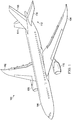
- aircraft 100 has wing 102 and wing 104 connected to body 106.
- Aircraft 100 includes engine 108 connected to wing 102 and engine 110 connected to wing 104.
- Body 106 has tail section 112. Horizontal stabilizer 114 , horizontal stabilizer 116 , and vertical stabilizer 118 are connected to tail section 112 of body 106.
- Aircraft 100 is an example of an aircraft having parts that may be inspected using a laser inspection system connected to a robotic arm, connected to a base of a crane system. For example, during manufacturing, components of at least one of wing 102 , wing 104 , body 106 , or tail section 112 may be inspected using the described method and system for automated data collection and part validation.
- Aircraft 100 may include fuel lines, hydraulic lines, and other conduits (not shown) that carry flammable fluids such as fuel, hydraulic fluid, or a lubricant such as engine oil. Disclosed examples of the flame arrestor described in more detail below may be used in or in conjunction with these conduits.
- a vehicle frame structure includes a fluid housing component that is at least partially filled with a combustible fluid or configured to be at least partially filled with a combustible fluid, a quenching element disposed within an inner chamber of the fluid housing component, and a cooling element thermally coupled to the quenching element to maintain a temperature of the quenching element below a threshold temperature.
- the vehicle may be, for example, one of an airplane, a helicopter, a space capsule, a satellite, an automobile, a train, a ship, and a submarine.
- the threshold temperature may be a temperature sufficiently cold to prevent combustion of the flammable liquid or to prevent a flame produced by the flammable liquid from propagating through the fluid housing component beyond a certain point.
- the cooling element maintains a temperature of the quenching element below a combustion temperature of the combustible fluid.
- the threshold temperature may simply be some temperature below ambient temperature.
- the threshold temperature is determined according to one or more properties of the combustible fluid.
- a number of when used with reference items, means one or more items.
- a number of different types of networks is one or more different types of networks.
- the phrase "at least one of,” when used with a list of items, means that different combinations of one or more of the listed items may be used, and only one of each item in the list may be needed. In other words, “at least one of” means any combination of items and any number of items may be used from the list, but not all of the items in the list are required.
- the item may be a particular object, a thing, or a category.
- At least one of item A, item B, or item C may include item A, item A and item B, or item B. This example also may include item A, item B, and item C or item B and item C. Of course, any combinations of these items may be present. In some illustrative examples, "at least one of” may be, for example, without limitation, two of item A; one of item B; and ten of item C; four of item B and seven of item C; or other suitable combinations.
- aircraft 100 is provided for purposes of illustrating one environment in which the different illustrative examples may be implemented.
- the illustration of aircraft 100 in Figure 1 is not meant to imply architectural limitations as to the manner in which different illustrative examples may be implemented.
- aircraft 100 is shown as a commercial passenger aircraft.
- the different illustrative examples may be applied to other types of aircraft, such as a private passenger aircraft, a rotorcraft, or other suitable types of aircraft.
- the structure may be, for example, a mobile structure, a stationary structure, a land-based structure, an aquatic-based structure, or a space-based structure. More specifically, the structure may be a surface ship, a tank, a personnel carrier, an automobile, a train, a spacecraft, a space station, a satellite, a submarine, a manufacturing facility, a building, or other suitable structures.
- FIG. 2 is a block diagram of an illustrative example of a flame arrestor 202 .
- flame arrestors are passive devices used to stop the propagation of fires or uncontrolled flames. Flame arrestors are placed between two zones filled with flammable fluids, such as flammable gas mixtures.
- a flame arrestor 202 is disposed within a conduit 200 between zone A 204 and zone B 206.
- the flame arrestor 202 prevents the propagation of a fire or a flame from zone A 204 to zone B 206 and vice versa.
- the flame arrestor remains permeable to the flow of flammable fluids (i.e., gases and/or liquids) which can freely transit between zone A 204 and zone B 206.
- the flame arrestor 202 stops the combustion front from reaching zone A 204 or zone B 206 and also avoids propagation of any ignition source to the other zone, such as hot jets or chemically active gases, while flow of inherently safe fluids is not impeded.
- flame arrestor technologies are based on the principle that hot reactive flows, referred to herein as flames, or combustion products loose heat to surrounding solid surfaces that are at ambient temperature. Practically, flames cannot sustain and propagate in cavities whose dimensions are smaller than a quenching distance, function of the fuel and the fuel-air ratio. Similarly, the hot combustion products of the flame become inherently safe as they travel through the cavity because they are cooled down due to convective heat transfers with solid surfaces at ambient temperature.
- Figure 3 is a graph 300 of a temperature of a quenching element versus the quenching distance for a stoichiometric methane-air flame according to an illustrative example.
- the quenching distance ⁇ q of a stoichiometric methane-air flame, at atmospheric pressure increases by a factor of 2 when the temperature of the quenching element is decreased from ambient (20°C) to 200 K (-73°C).
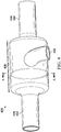
- FIG. 4 is a diagram of an illustrative example of a flame arrestor 400.
- Flame arrestor 400 includes an entrance pipe 402 and an exit pipe 404 with a flame arrestor chamber 406 disposed between the pipes 402 , 404.
- a flammable fluid flows through the flame arrestor 400 from entrance pipe 402 through the flame arrestor chamber 406 and exiting through the exit pipe 404.
- the flame arrestor chamber 406 includes quenching elements (not shown) and a cooling element (not shown) for cooling the quenching elements of the flame arrestor 400 during operation of the cooling system.
- the quenching elements are disposed within the flame arrestor chamber 406 and are in thermal contact with the cooling system.
- flame arrestor 400 also includes a cooling element conduit 408 for providing a cooling fluid to the cooling element and/or electrical connections to connect the cooling element to an external power supply if cooling is accomplished via thermoelectric cooling Peltier devices. Heat extracted from the quenching elements by the cooling element is removed from the flame arrestor 400 via the cooling element conduit 408.
- the cooling element includes an apparatus for providing a chemical endothermic reaction of two or more chemical agents.
- the cooling element is a Joule-Thomson effect cooler.
- the cooling of the flame arrestor quenching elements can be made by any number of cooling systems including, for example, by a flow of liquid nitrogen, by a flow of cold fluid such as air or water, by a refrigeration system including those based on thermoelectric Peltier effect (e.g., cooling by applying a voltage difference at the junction between two conductive materials), or naturally, by immersing the flame arrestor chamber 406 in a cold environment such as ice, an ice-water mixture, high-altitude atmosphere, or the vacuum of empty space.
- the cooling of the flame arrestor quenching elements may also be performed by a sudden mixing of two chemical agents that would produce an endothermic reaction.
- dissolution of salt in a solvent is typically an endothermic process (ammonium in water, potassium chloride in water, sodium carbonate in ethanoic acid, etc.).
- the cooling of the flame arrestor quenching elements may be performed using the Joule-Thomson effect (i.e., rapid adiabatic gas expansion).
- the quenching element has channels in which walls of the channels have a number of dimensions and a temperature that are selected to reduce a temperature of a combustible fluid below an ignition temperature of the combustible fluid.
- the number of dimensions includes a distance between opposing walls of a channel and that distance reduces the temperature of a combustible fluid below the ignition temperature of the combustible fluid where the distance is selected based on a quenching distance determined using a cooled temperature of the quenching element.
- the cooled temperature of the quenching elements is a cryogenic temperature.
- a cryogenic temperature is a temperature at or below -150°C.
- the cooling system is selected from a group consisting of at least one of an active cooling system, a passive cooling system, a thermoelectric cooler (also referred to as a thermoelectric Peltier cooler), a water cooler, an air cooler, or a liquid nitrogen cooler.
- a thermoelectric cooler also referred to as a thermoelectric Peltier cooler
- the pipes 402 , 404 are part of a fluid transport system that transports fluids.
- the fluids are, for example, a fuel, gasoline, kerosene, methane, ethane, propane, butane, ethylene, hydrogen, acetylene, ammonia, carbon monoxide, syngas, ethanol, methanol, propanol, dimethoxyethane (DME), and oxygen.
- the fluids are a flammable fluid including both flammable gasses and flammable liquids.
- the fluids may be a fuel, a gasoline, kerosene, methane, ethane, propane, butane, ethylene, hydrogen, acetylene, ammonia, carbon monoxide, syngas, ethanol, methanol, propanol, DME, and oxygen.
- the fluids may be a mixture of two or more substances.
- the fluids includes both a liquid and a gas.
- the quenching elements are disposed within an inner volume of the fluid transport pipe and the quenching element is fabricated at least partially from a flame arresting material.
- the flame arresting material is a metal, a ceramic, or a plastic.
- the metal may be, for example, one of aluminum, stainless steel, Inconel, iron, copper, brass, bronze, and titanium.
- Plastics include polyamides, polycarbonates, polyethylenes, polypropylenes, polyvinyl-chloride, and acrylonitrile-butadiene styrene. Other materials may be used for the flame arresting material.
- the flame arresting material should be a solid at the temperatures anticipated to be present in the flame arrestor.
- the flame arresting materials are materials that are solids at the combustion temperature of the fluid flowing through the conduit.
- the quenching elements include a plurality of quenching element tubes wherein each of the quenching element tubes includes an opening for the fluid to flow through and the opening has a diameter greater than or equal to 1 millimeter (mm).
- the quenching elements are a single quenching element.
- the single quenching element is an inner surface of the fluid transport pipe.
- the cooling element surrounds a portion of the pipes.
- the cooling element is integrated as at least a portion of a wall of the fluid transport pipe.
- the cooling element is a hollow component filled or partially filled with cool fluids or a cooling fluid that flows through the cooling element to extract heat from the quenching element, thereby cooling the quenching element.
- the cooling fluid is a gas or a liquid.
- the gas is air.
- the liquid is a cryogenic liquid such as liquid nitrogen or liquid helium.
- the cooling element includes one or more thermoelectric Peltier coolers.
- the cooling element includes a plurality of reservoirs each storing a respective chemical agent that when mixed together inside the cooling element near to the quenching elements produce an endothermic reaction thereby cooling the quenching elements.
- Dissolution of salt in a solvent is typically an endothermic process.
- substances which when combined produce an endothermic reaction include ammonium in water, potassium chloride in water, and sodium carbonate in ethanoic acid.
- the cooling element includes a cooling system implementing the Joule-Thomson effect to cool the quenching elements by rapid adiabatic gas expansion.
- the cooling element encases or is encased in a refrigerating solution such as an ice water mixture.
- the cooling element is a deformable material.
- the cooling element includes a tube or tubes for a cooling fluid to circulate around at least a portion of the quenching elements having a surface exposed to the cooling element and for the fluid to flow away from the quenching elements through a heat exchanger to dissipate heat removed from the quenching elements.
- Some benefits of one or more examples of the disclosed flame arrestors as compared to conventional flame arrestors are a decrease in the pressure loss the flame arrestor will induce on any flowing fluid (pressure loss scales with the inverse of the quenching element's characteristic dimension to the power of 5).
- Other benefits of one or more examples of the disclosed flame arrestors are a weight reduction of the flame arrestor associated with the decrease of the required functional quenching surface area.
- Another benefit of one or more examples of the disclosed cooling element is that a separate flame arrestor part may be eliminated altogether if the conduit's diameter is sufficiently small enough to quench flames itself.
- the inner wall of the conduit is the flame arrestor and this inner wall is the quenching element.
- the disclosed cooling element increases the allowable diameter of an inherently safe conduit.
- One application of the disclosed devices, methods, and systems is the control of fire and/or flame propagation in systems that require a large flow rate (and, as a consequence, small pressure losses through the flame arrestor) and/or that are weight sensitive.
- the disclosed examples allow reduction of detrimental pressure losses compared to prior art conventional flame arrestors and provide for a comparable flame quenching efficiency. This allows for a reduction in the functional quenching surface area of the quenching elements leading to weight savings.
- Flame arrestors are of interest for mitigation of fire and/or flame related hazard for any device that is weight sensitive such as planes, helicopters, drones, or satellites or that requires large flow rates with minimal pressure loss, such as for fuel injection systems or fuel pipes.
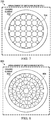
- FIG. 5-8 cross sectional views of the flame arrestor 400 showing different configurations of the quenching elements are depicted in accordance with illustrative examples.
- the cross sectional views in Figures 5-8 are taken at cross section A in Figure 4 .
- FIG 5 shows a flame arrestor 500 with cooling element 502 surrounding a plurality of quenching elements 504.
- the flame arrestor 500 may be implemented as flame arrestor 400 depicted in Figure 4 .
- the quenching elements 504 include variously shaped quenching elements that are not all uniformly shaped.
- the quenching elements 504 are arranged in a fashion similar to a kaleidoscope with some elements having triangular like shapes and other elements having a wedge like shape and still other elements having a polygon like shape.
- the surfaces of each quenching element 504 extend longitudinally through the flame arrestor 400 such that fluid flows through pipe 402 and into pipe 404 through the quenching elements 504.
- FIG 6 shows a flame arrestor 600 with cooling element 602 surrounding a plurality of quenching elements 604.
- the flame arrestor 600 may be implemented as flame arrestor 400 depicted in Figure 4 .
- the quenching elements 604 are mostly uniform in shape and size, although variations in shape and size are allowable.
- the quenching elements 604 are generally polygonal in shape. The surfaces of each quenching element 604 extend longitudinally through the flame arrestor 400 such that fluid flows through pipe 402 and into pipe 404 through the quenching elements 604.
- FIG 7 shows a flame arrestor 700 with cooling element 702 surrounding a plurality of quenching elements 704.
- the flame arrestor 700 may be implemented as flame arrestor 400 depicted in Figure 4 .
- the quenching elements 704 are mostly uniform in shape and size, although, as with flame arrestor 600 , variations in shape and size are allowable.
- the quenching elements 704 are generally circular in shape with some neighboring quenching elements 704 touching and others separated by a small gap formed by the joining of four neighboring quenching elements 704.
- the surfaces of each quenching element 704 extend longitudinally through the flame arrestor 400 such that fluid flows through pipe 402 and into pipe 404 through the quenching elements 704.
- FIG 8 shows a flame arrestor 800 with cooling element 802 surrounding a plurality of quenching elements 804.
- the flame arrestor 800 may be implemented as flame arrestor 400 depicted in Figure 4 .
- the quenching elements 804 are mostly uniform in shape and size, although, as with flame arrestor 600 , variations in shape and size are allowable.
- the quenching elements 804 are generally arranged in a kaleidoscope type fashion similar to flame arrestor 500 , but with some wedge-shaped elements replaced by elements resembling flower petals or leaves. Again, the surfaces of each quenching element 804 extend longitudinally through the flame arrestor 400 such that fluid flows through pipe 402 and into pipe 404 through the quenching elements 804.
- Flame arrestors 500 , 600 , 700 , and 800 are provided as examples of shapes and arrangements that the quenching elements may take. However, any number of alternative shapes may be utilized in other examples of flame arrestors.
- the quenching elements is arranged in a spiraling shape such that the position of the quenching elements within the conduit varies as a fluid traverses the length of the flame arrestor.
- the position of each quenching element within the conduit stays relatively the same as the fluid traverses the quenching element such that flow of the fluid through the flame arrestor is not impeded.
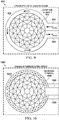
- Figures 9-12 are cross sectional diagrams of flame arrestor 400 showing illustrative examples of cooling elements.
- the cross-sectional views in Figures 9-12 are taken at cross section A in Figure 4 .
- FIG 9 shows an illustrative example of a flame arrestor 900 using liquid nitrogen to cool the quenching elements.
- the flame arrestor 900 may be implemented as flame arrestor 400 depicted in Figure 4 .
- the flame arrestor 900 includes a cooling element 902 and quenching elements 904.
- the cooling element 902 is a hollow cylinder surrounding the quenching elements 902 which are disposed within an interior of the flame arrestor 900.
- the cooling element 902 is in thermal contact with the quenching elements 904.
- the cooling element 902 includes an ingress pathway 906 and egress pathway 908 for liquid nitrogen to flow into a main chamber of the cooling element 902 and around at least portions of the quenching elements 904. In some examples, other fluids other than liquid nitrogen are used.
- cryogenic fluid is liquid helium.
- the cooling element 902 surrounds an outside of the flame arrestor 900 main cavity or a conduit housing the flame arrestor 900. However, in some examples, the cooling element 902 is only surround a portion of the flame arrestor 900 main cavity or a conduit housing the flame arrestor 900.
- FIG 10 shows an illustrative example of a flame arrestor 1000 using thermoelectric cooling elements.
- Flame arrestor 1000 may be implemented as flame arrestor 400 in Figure 4 .
- Flame arrestor 1000 includes a cooling element 1002 and a plurality of quenching elements 1004.
- the cooling element 1002 includes a plurality of thermoelectric Peltier coolers surrounding the cavity housing the quenching elements 1004.
- the Peltier coolers are connected to an electric power supply by positive and negative electrical conduits 1006 , 1008.
- the cooling element is arranged in multiple different manners similar to the various examples described above with respect to Figure 9 .
- FIG 11 shows an illustrative example of a flame arrestor 1100 using cold air to cool the quenching elements.
- the flame arrestor 1100 may be implemented as flame arrestor 400 depicted in Figure 4 .
- the flame arrestor 1100 is similar to flame arrestor 900 depicted in Figure 9 and includes a cooling element 1102 and quenching elements 1104.
- the cooling element 1102 is a hollow cylinder surrounding the quenching elements 1102 which are disposed within an interior of the flame arrestor 1100.
- the cooling element 1102 is in thermal contact with the quenching elements 1104.
- the cooling element 1102 includes an ingress pathway 1106 and egress pathway 1108 for cold air to flow into a main chamber of the cooling element 1102 and around at least portions of the quenching elements 1104.
- the fluid flowing through the cooling element 1102 is a chilled noble gas or some other gas or gas mixture.
- the cooling element 1102 surrounds an outside of the flame arrestor 1100 main cavity or a conduit housing the flame arrestor 1100.
- the cooling element 1102 may only surround a portion of the flame arrestor 1100 main cavity or a conduit housing the flame arrestor 1100.
- FIG 12 shows an illustrative example of a flame arrestor 1200 using ice to cool the quenching elements.
- the flame arrestor 1200 may be implemented as flame arrestor 400 depicted in Figure 4 .
- the flame arrestor 1200 includes a cooling element 1202 and quenching elements 1204.
- the cooling element 1202 is a hollow or solid cylinder surrounding the quenching elements 1202 which are disposed within an interior of the flame arrestor 1200.
- the cooling element 1202 is in thermal contact with the quenching elements 1204.
- the cooling element 1202 is surrounded by a cold solid or liquid solid mixture. For example, the cooling element 1202 is immersed in ice, an ice-water mixture, or dry-ice.
- the cooling element 1202 is formed of a deformable material such that expansion or contraction of the ice or other material in which the cooling element 1202 is immersed does not cause damage to the flame arrestor 1200 main body or the conduits.
- the cooling element 1202 surrounds an outside of the flame arrestor 1200 main cavity or a conduit housing the flame arrestor 1200.
- the cooling element 1202 may only surround a portion of the flame arrestor 1200 main cavity or a conduit housing the flame arrestor 1200.
- FIG. 13 is a block diagram showing an illustrative example of a flame arrestor system 1300.
- Flame arrestor system 1300 includes a conduit 1301 (e.g., a pipe) and a flame arrestor 1302.
- the flame arrestor 1302 may be integrated into the conduit 1301 or otherwise coupled to it such that flammable fluid 1330 (i.e., combustible fluid) flowing through the conduit 1301 flows through the flame arrestor 1302 before exiting into a different section of the conduit 1301.
- the flame arrestor 1302 includes one or more quenching element(s) 1304 and a cooling element 1306.
- the flammable fluid 1330 is a gas 1332 , a liquid 1334 , a fuel 1336 , a lubricant 1338 , or hydraulic fluid 1340.
- the quenching element(s) 1304 is a single quenching element 1308 or multiple quenching elements 1310.
- a single quenching element 1308 is integrated with or be the inner surface of the conduit 1301.
- the multiple quenching elements 1310 are uniformly shaped and/or sized quenching elements 1312 or are non-uniformly shaped and/or sized quenching elements 1314.
- the cooling element 1306 is a cryogenic liquid cooler 1316 , a cool gas cooler 1318 , a thermoelectric Peltier cooler 1320 , a chemical endothermic reaction cooler 1322 , or a Joule-Thomson Effect Cooler 1324. In other examples, other types of coolers may be implemented as the cooling element 1306.
- the method 1400 includes directing a combustible fluid through a quenching element disposed within a pipe (step 1402 ). The method also includes cooling the quenching element with a cooling element in thermal contact with the quenching element such that the quenching element is cooled below a threshold temperature (step 1404) .
- each block in the flowcharts or block diagrams represent a module, a segment, a function, and/or a portion of an operation or step.
- aircraft 1500 may include airframe 1502 with plurality of systems 1504 and interior 1506.
- systems 1504 include one or more of propulsion system 1508 , electrical system 1510 , hydraulic system 1512 , and environmental system 1514. Any number of other systems are included.
- propulsion system 1508 electrical system 1510
- hydraulic system 1512 hydraulic system 1512
- environmental system 1514 any number of other systems are included.
- an aerospace example is shown, different illustrative examples may be applied to other industries, such as the automotive industry.
- Apparatuses and methods embodied herein may be employed in one or more components of aircraft 1500.
Landscapes
- Health & Medical Sciences (AREA)
- Public Health (AREA)
- Business, Economics & Management (AREA)
- Emergency Management (AREA)
- Chemical & Material Sciences (AREA)
- Engineering & Computer Science (AREA)
- Chemical Kinetics & Catalysis (AREA)
- General Chemical & Material Sciences (AREA)
- Oil, Petroleum & Natural Gas (AREA)
- Cooling Or The Like Of Electrical Apparatus (AREA)
Abstract
Description
- The disclosure relates generally to control of flammable fluids and more specifically to flame arrestors.
- A flame arrestor is a device that stops fuel combustion by extinguishing the flame. Flame arrestors are used to stop the spread of an open fire, to limit the spread of an explosive even that has occurred, to protect potentially explosive mixtures from igniting, to confine fire within an enclosed, controlled, or regulated location, and to stop the propagation of a flame. Flame arrestors are commonly used in fuel storage tank vents, fuel gas pipelines, and other areas. One problem with prior art flame arrestors is that they have a high density of quenching elements in order to quench the flame. However, the high density of quenching elements reduces the flow of fluid through a pipe as well as adds weight.
- Therefore, it would be desirable to have a method and apparatus that take into account at least some of the issues discussed above, as well as other possible issues. For example, it would be desirable to have a method and apparatus that overcome a technical problem with fluid flow and weight in a flame arrestor.
- In one illustrative example, a flame arrestor is presented. The flame arrestor includes a quenching element disposed within a conduit. The flame arrestor also includes a cooling system in thermal contact with the quenching system. The cooling system cools the quenching element during operation of the cooling system.
- In another illustrative example, a flame arrestor is presented. The flame arrestor includes a fluid transport pipe for transporting a combustible fluid from a first point to a second point. The flame arrestor also includes a quenching element disposed within an inner volume of the fluid transport pipe. The quenching element is at least partially constructed from a flame arresting material. The flame arrestor also includes a cooling element in thermal contact with the quenching element. The cooling element is configured to cool the quenching element below a threshold temperature.
- In yet another illustrative example, a method for arresting a flame in a pipe carrying a combustible fluid is presented. The method includes directing the combustible fluid through a quenching element disposed within the pipe. The method also includes cooling the quenching element with a cooling element in thermal contact with the quenching element. The quenching element is cooled below a threshold temperature.
- In another illustrative example, a vehicle is provided. The vehicle includes a vehicle frame structure and a fluid housing conduit within the vehicle frame structure. The fluid housing conduit configured to be at least partially filled with a combustible fluid. The vehicle also includes a quenching element disposed within an inner chamber of the fluid housing conduit. The quenching element includes a flame arresting material. The vehicle also includes a cooling element thermally coupled to the quenching element to maintain a temperature of the quenching element below a threshold temperature.
-
-
Figure 1 is an illustration of an aircraft in which an illustrative example may be implemented; -
Figure 2 is an illustration of a block diagram of a flame arrestor in accordance with an illustrative example; -
Figure 3 is an illustration of a graph of temperature of a quenching element versus the quenching distance for a stoichiometric methane-air flame in accordance with an illustrative example; -
Figure 4 is an illustration of a diagram of a flame arrestor in accordance with an illustrative example; -
Figures 5-8 are illustrations of cross-sectional views of the flame arrestor showing different configurations of the quenching elements in accordance with an illustrative example; -
Figures 9-12 are illustrations of cross-sectional diagrams of a flame arrestor showing cooling elements in accordance with an illustrative example; -
Figure 13 is an illustration of a block diagram of a flame arrestor system in accordance with an illustrative example; -
Figure 14 is an illustration of a block diagram of a flame arresting system in accordance with an illustrative example; and -
Figure 15 is an illustration of a block diagram of an aircraft in which an illustrative example may be implemented. - The different illustrative examples recognize and take into account one or more different considerations. For example, the illustrative examples recognize and take into account that conduits carrying flammable fluids often require flame arrestors to quench a flame thereby preventing a flame from propagating beyond a particular point in the conduit. Additionally, the illustrative examples recognize and take into account that in many applications, a flame arrestor may be desirable to have a reduced surface area such that the flow of a fluid through a conduit is not significantly impeded and that little or no pressure drop is experienced by the fluid as it traverses through the flame arrestor. The illustrative examples recognize and take into account that the weight is a significant issue in some applications, such as for use in aircraft. Thus, illustrative examples provide a flame arrestor that has a reduced weight as compared to prior art flame arrestors while providing equivalent flame arresting. In other examples, a flame arrestor having a weight, similar to a prior art flame arrestor, provides improved flame arresting as compared to the prior art.
- Understanding flame quenching is beneficial in developing efficient flame arrestors and to increase the safety of practical combustion systems, such as aircrafts. It is an insight of this disclosure that inflight, pressure and temperature are much different than at sea level with typically: T < 220 K and P < 25,000 Pa. While effects of pressures below atmospheric on flame quenching distance are known, there are no data available for temperatures below T = 300 K. One goal of this disclosure is to fill this gap. In an example, this is done by measuring the quenching distance of methane-air laminar flames in the canonical head-on configuration, where the temperature of the quenching plate is adjusted between T = 175 and 300 K. Temperature is adjusted using liquid nitrogen and is monitored with a thermocouple. The quenching distance is measured by recording the transient quenching event with a high-speed camera targeting OH* chemiluminescence. The setup and methods are first validated by measuring the quenching distance at T = 300 K and different equivalence ratios and comparing values to that available in the literature. Then, the quenching distance is measured for T = 175 to 300 K. It is an insight of this disclosure that the quenching distance decreases linearly with temperature decrease and is divided by two over the temperature range examined.
- In another example, the quenching distance of methane-air laminar flames is measured in the canonical head-on configuration, where the temperature of the quenching plate is adjusted between T = 175 and 300 K. Temperature is adjusted using liquid nitrogen and is monitored with a thermocouple. The quenching distance is measured by recording the transient quenching event with a high-speed camera targeting OH* chemiluminescence. The setup and methods are first validated by measuring the quenching distance at T = 300 K and different equivalence ratios and comparing values to that available in the literature. Then, the quenching distance is measured for T = 175 to 300 K. The quenching distance decreases with temperature increase over the temperature range examined.
- Disclosed herein are flame arrestors and methods and systems for arresting flames in a fluid conduit. In an aspect, a method for arresting a flame includes cooling of the quenching surface down to very low temperatures. In some examples, the quenching surface is cooled down to cryogenic temperatures. In an example, a flame arrestor includes a quenching element disposed within a conduit for propagating the flow of a combustible fluid. The quenching element is in thermal contact with a cooling element that cools the quenching element sufficiently such that a flame does not propagate past some specified point. In other words, the flame is extinguished before the flame can propagate past some specified point either within the flame arrestor or a certain distance from the end of the flame arrestor. In some examples, the quenching element is cooled sufficiently such that the combustible fluid maintains a temperature below its combustion temperature.
- In an illustrative example, a method for arresting a flame in a pipe carrying a combustible fluid includes directing the combustible fluid through a quenching element disposed within the pipe; and cooling the quenching element with a cooling element in thermal contact with the quenching element, the quenching element cooled below a threshold temperature. In an illustrative example, the cooling the quenching element includes providing a flow of cool fluids through the cooling element to extract heat from the quenching element. In an illustrative example, the cool fluids are selected from one of liquid nitrogen, liquid helium, and cold air. In an illustrative example, cooling the quenching element includes removing heat from the cooling elements via a thermoelectric Peltier cooler. In an example, the cooling of the quenching element includes immersing the cooling element in ice or an ice water mixture. In an illustrative example, the quenching element includes an inner surface of the pipe through which the combustible fluid flows.
- The disclosed examples of a flame arrestor may be used in a pipe or conduit as described in more detail below. In some examples, the conduit is a container for containing flammable fluids such as fuel (e.g., a fuel tank).
- Examples are described below with reference to flowchart illustrations and/or block diagrams of methods, apparatus (systems) and computer program products according to certainexamples. It will be understood that each block of the flowchart illustrations and/or block diagrams, and combinations of blocks in the flowchart illustrations and/or block diagrams, can be implemented by computer-readable program instructions.
- Referring now to the figures and, in particular, with reference to
Figure 1 , an illustration of an aircraft is depicted in which an illustrative example may be implemented. In this illustrative example,aircraft 100 haswing 102 andwing 104 connected tobody 106.Aircraft 100 includesengine 108 connected towing 102 andengine 110 connected towing 104. -
Body 106 hastail section 112.Horizontal stabilizer 114,horizontal stabilizer 116, andvertical stabilizer 118 are connected totail section 112 ofbody 106. -
Aircraft 100 is an example of an aircraft having parts that may be inspected using a laser inspection system connected to a robotic arm, connected to a base of a crane system. For example, during manufacturing, components of at least one ofwing 102,wing 104,body 106, ortail section 112 may be inspected using the described method and system for automated data collection and part validation. -
Aircraft 100 may include fuel lines, hydraulic lines, and other conduits (not shown) that carry flammable fluids such as fuel, hydraulic fluid, or a lubricant such as engine oil. Disclosed examples of the flame arrestor described in more detail below may be used in or in conjunction with these conduits. In an example, a vehicle frame structure includes a fluid housing component that is at least partially filled with a combustible fluid or configured to be at least partially filled with a combustible fluid, a quenching element disposed within an inner chamber of the fluid housing component, and a cooling element thermally coupled to the quenching element to maintain a temperature of the quenching element below a threshold temperature. The vehicle may be, for example, one of an airplane, a helicopter, a space capsule, a satellite, an automobile, a train, a ship, and a submarine. The threshold temperature may be a temperature sufficiently cold to prevent combustion of the flammable liquid or to prevent a flame produced by the flammable liquid from propagating through the fluid housing component beyond a certain point. In an example, the cooling element maintains a temperature of the quenching element below a combustion temperature of the combustible fluid. In some examples, the threshold temperature may simply be some temperature below ambient temperature. In an example, the threshold temperature is determined according to one or more properties of the combustible fluid. - As used herein, "a number of" when used with reference items, means one or more items. For example, "a number of different types of networks" is one or more different types of networks.
- Further, the phrase "at least one of," when used with a list of items, means that different combinations of one or more of the listed items may be used, and only one of each item in the list may be needed. In other words, "at least one of" means any combination of items and any number of items may be used from the list, but not all of the items in the list are required. The item may be a particular object, a thing, or a category.
- For example, without limitation, "at least one of item A, item B, or item C" may include item A, item A and item B, or item B. This example also may include item A, item B, and item C or item B and item C. Of course, any combinations of these items may be present. In some illustrative examples, "at least one of" may be, for example, without limitation, two of item A; one of item B; and ten of item C; four of item B and seven of item C; or other suitable combinations.
- This illustration of
aircraft 100 is provided for purposes of illustrating one environment in which the different illustrative examples may be implemented. The illustration ofaircraft 100 inFigure 1 is not meant to imply architectural limitations as to the manner in which different illustrative examples may be implemented. For example,aircraft 100 is shown as a commercial passenger aircraft. The different illustrative examples may be applied to other types of aircraft, such as a private passenger aircraft, a rotorcraft, or other suitable types of aircraft. - Although the illustrative examples for an illustrative example are described with respect to an aircraft, the illustrative examples may be applied to other types of structures. The structure may be, for example, a mobile structure, a stationary structure, a land-based structure, an aquatic-based structure, or a space-based structure. More specifically, the structure may be a surface ship, a tank, a personnel carrier, an automobile, a train, a spacecraft, a space station, a satellite, a submarine, a manufacturing facility, a building, or other suitable structures.
-
Figure 2 is a block diagram of an illustrative example of aflame arrestor 202. Typically, flame arrestors are passive devices used to stop the propagation of fires or uncontrolled flames. Flame arrestors are placed between two zones filled with flammable fluids, such as flammable gas mixtures. Thus, for example, aflame arrestor 202 is disposed within aconduit 200 betweenzone A 204 andzone B 206. Theflame arrestor 202 prevents the propagation of a fire or a flame fromzone A 204 tozone B 206 and vice versa. However, the flame arrestor remains permeable to the flow of flammable fluids (i.e., gases and/or liquids) which can freely transit betweenzone A 204 andzone B 206. Thus, theflame arrestor 202 stops the combustion front from reachingzone A 204 orzone B 206 and also avoids propagation of any ignition source to the other zone, such as hot jets or chemically active gases, while flow of inherently safe fluids is not impeded. - Usually, flame arrestor technologies are based on the principle that hot reactive flows, referred to herein as flames, or combustion products loose heat to surrounding solid surfaces that are at ambient temperature. Practically, flames cannot sustain and propagate in cavities whose dimensions are smaller than a quenching distance, function of the fuel and the fuel-air ratio. Similarly, the hot combustion products of the flame become inherently safe as they travel through the cavity because they are cooled down due to convective heat transfers with solid surfaces at ambient temperature.
- It is an insight of this disclosure that the quenching distance of a flame interacting with a solid surface increases when the solid surface temperature is decreased.
-
Figure 3 is agraph 300 of a temperature of a quenching element versus the quenching distance for a stoichiometric methane-air flame according to an illustrative example. As shown inFigure 3 , the quenching distance δq of a stoichiometric methane-air flame, at atmospheric pressure, increases by a factor of 2 when the temperature of the quenching element is decreased from ambient (20°C) to 200 K (-73°C). -
Figure 4 is a diagram of an illustrative example of aflame arrestor 400.Flame arrestor 400 includes anentrance pipe 402 and anexit pipe 404 with aflame arrestor chamber 406 disposed between thepipes flame arrestor 400 fromentrance pipe 402 through theflame arrestor chamber 406 and exiting through theexit pipe 404. Theflame arrestor chamber 406 includes quenching elements (not shown) and a cooling element (not shown) for cooling the quenching elements of theflame arrestor 400 during operation of the cooling system. The quenching elements are disposed within theflame arrestor chamber 406 and are in thermal contact with the cooling system. In an example, thepipes flame arrestor chamber 406 have the same diameter and the quenching element is disposed within the pipe or conduit. In an example,flame arrestor 400 also includes acooling element conduit 408 for providing a cooling fluid to the cooling element and/or electrical connections to connect the cooling element to an external power supply if cooling is accomplished via thermoelectric cooling Peltier devices. Heat extracted from the quenching elements by the cooling element is removed from theflame arrestor 400 via thecooling element conduit 408. In an example, the cooling element includes an apparatus for providing a chemical endothermic reaction of two or more chemical agents. In an example, the cooling element is a Joule-Thomson effect cooler. - The cooling of the flame arrestor quenching elements can be made by any number of cooling systems including, for example, by a flow of liquid nitrogen, by a flow of cold fluid such as air or water, by a refrigeration system including those based on thermoelectric Peltier effect (e.g., cooling by applying a voltage difference at the junction between two conductive materials), or naturally, by immersing the
flame arrestor chamber 406 in a cold environment such as ice, an ice-water mixture, high-altitude atmosphere, or the vacuum of empty space. The cooling of the flame arrestor quenching elements may also be performed by a sudden mixing of two chemical agents that would produce an endothermic reaction. For example, dissolution of salt in a solvent is typically an endothermic process (ammonium in water, potassium chloride in water, sodium carbonate in ethanoic acid, etc.). In yet another example, the cooling of the flame arrestor quenching elements may be performed using the Joule-Thomson effect (i.e., rapid adiabatic gas expansion). - In an example, the quenching element has channels in which walls of the channels have a number of dimensions and a temperature that are selected to reduce a temperature of a combustible fluid below an ignition temperature of the combustible fluid. In an example, the number of dimensions includes a distance between opposing walls of a channel and that distance reduces the temperature of a combustible fluid below the ignition temperature of the combustible fluid where the distance is selected based on a quenching distance determined using a cooled temperature of the quenching element. In an example, the cooled temperature of the quenching elements is a cryogenic temperature. In an example, a cryogenic temperature is a temperature at or below -150°C.
- In an example, the cooling system is selected from a group consisting of at least one of an active cooling system, a passive cooling system, a thermoelectric cooler (also referred to as a thermoelectric Peltier cooler), a water cooler, an air cooler, or a liquid nitrogen cooler.
- In an example, the
pipes 402, 404 (also referred to as a conduit of a fluid transport pipe) are part of a fluid transport system that transports fluids. The fluids are, for example, a fuel, gasoline, kerosene, methane, ethane, propane, butane, ethylene, hydrogen, acetylene, ammonia, carbon monoxide, syngas, ethanol, methanol, propanol, dimethoxyethane (DME), and oxygen. In an example, the fluids are a flammable fluid including both flammable gasses and flammable liquids. For example, the fluids may be a fuel, a gasoline, kerosene, methane, ethane, propane, butane, ethylene, hydrogen, acetylene, ammonia, carbon monoxide, syngas, ethanol, methanol, propanol, DME, and oxygen. The fluids may be a mixture of two or more substances. In some examples, the fluids includes both a liquid and a gas. - In an example, the quenching elements are disposed within an inner volume of the fluid transport pipe and the quenching element is fabricated at least partially from a flame arresting material. The flame arresting material is a metal, a ceramic, or a plastic. The metal may be, for example, one of aluminum, stainless steel, Inconel, iron, copper, brass, bronze, and titanium. Plastics include polyamides, polycarbonates, polyethylenes, polypropylenes, polyvinyl-chloride, and acrylonitrile-butadiene styrene. Other materials may be used for the flame arresting material. The flame arresting material should be a solid at the temperatures anticipated to be present in the flame arrestor. In an example, the flame arresting materials are materials that are solids at the combustion temperature of the fluid flowing through the conduit. In an example, the quenching elements include a plurality of quenching element tubes wherein each of the quenching element tubes includes an opening for the fluid to flow through and the opening has a diameter greater than or equal to 1 millimeter (mm). In an example, the quenching elements are a single quenching element. In an example, the single quenching element is an inner surface of the fluid transport pipe.
- In an example, the cooling element surrounds a portion of the pipes. In an example, the cooling element is integrated as at least a portion of a wall of the fluid transport pipe. In an example, the cooling element is a hollow component filled or partially filled with cool fluids or a cooling fluid that flows through the cooling element to extract heat from the quenching element, thereby cooling the quenching element. The cooling fluid is a gas or a liquid. In an example, the gas is air. In example, the liquid is a cryogenic liquid such as liquid nitrogen or liquid helium. In an example, the cooling element includes one or more thermoelectric Peltier coolers. In an example, the cooling element includes a plurality of reservoirs each storing a respective chemical agent that when mixed together inside the cooling element near to the quenching elements produce an endothermic reaction thereby cooling the quenching elements. Dissolution of salt in a solvent is typically an endothermic process. Examples of substances which when combined produce an endothermic reaction include ammonium in water, potassium chloride in water, and sodium carbonate in ethanoic acid. In another example, the cooling element includes a cooling system implementing the Joule-Thomson effect to cool the quenching elements by rapid adiabatic gas expansion.
- In an example, the cooling element encases or is encased in a refrigerating solution such as an ice water mixture. In an example, the cooling element is a deformable material. In an example, the cooling element includes a tube or tubes for a cooling fluid to circulate around at least a portion of the quenching elements having a surface exposed to the cooling element and for the fluid to flow away from the quenching elements through a heat exchanger to dissipate heat removed from the quenching elements.
- Some benefits of one or more examples of the disclosed flame arrestors as compared to conventional flame arrestors are a decrease in the pressure loss the flame arrestor will induce on any flowing fluid (pressure loss scales with the inverse of the quenching element's characteristic dimension to the power of 5). Other benefits of one or more examples of the disclosed flame arrestors are a weight reduction of the flame arrestor associated with the decrease of the required functional quenching surface area. Another benefit of one or more examples of the disclosed cooling element is that a separate flame arrestor part may be eliminated altogether if the conduit's diameter is sufficiently small enough to quench flames itself. Thus, in these examples, the inner wall of the conduit is the flame arrestor and this inner wall is the quenching element. The disclosed cooling element increases the allowable diameter of an inherently safe conduit.
- One application of the disclosed devices, methods, and systems is the control of fire and/or flame propagation in systems that require a large flow rate (and, as a consequence, small pressure losses through the flame arrestor) and/or that are weight sensitive. The disclosed examples allow reduction of detrimental pressure losses compared to prior art conventional flame arrestors and provide for a comparable flame quenching efficiency. This allows for a reduction in the functional quenching surface area of the quenching elements leading to weight savings. Flame arrestors are of interest for mitigation of fire and/or flame related hazard for any device that is weight sensitive such as planes, helicopters, drones, or satellites or that requires large flow rates with minimal pressure loss, such as for fuel injection systems or fuel pipes.
- Turning now to
Figures 5-8 , cross sectional views of theflame arrestor 400 showing different configurations of the quenching elements are depicted in accordance with illustrative examples. The cross sectional views inFigures 5-8 are taken at cross section A inFigure 4 . -
Figure 5 shows aflame arrestor 500 withcooling element 502 surrounding a plurality of quenchingelements 504. Theflame arrestor 500 may be implemented asflame arrestor 400 depicted inFigure 4 . The quenchingelements 504 include variously shaped quenching elements that are not all uniformly shaped. The quenchingelements 504 are arranged in a fashion similar to a kaleidoscope with some elements having triangular like shapes and other elements having a wedge like shape and still other elements having a polygon like shape. The surfaces of each quenchingelement 504 extend longitudinally through theflame arrestor 400 such that fluid flows throughpipe 402 and intopipe 404 through the quenchingelements 504. -
Figure 6 shows aflame arrestor 600 withcooling element 602 surrounding a plurality of quenchingelements 604. Theflame arrestor 600 may be implemented asflame arrestor 400 depicted inFigure 4 . The quenchingelements 604 are mostly uniform in shape and size, although variations in shape and size are allowable. The quenchingelements 604 are generally polygonal in shape. The surfaces of each quenchingelement 604 extend longitudinally through theflame arrestor 400 such that fluid flows throughpipe 402 and intopipe 404 through the quenchingelements 604. -
Figure 7 shows aflame arrestor 700 withcooling element 702 surrounding a plurality of quenchingelements 704. Theflame arrestor 700 may be implemented asflame arrestor 400 depicted inFigure 4 . The quenchingelements 704 are mostly uniform in shape and size, although, as withflame arrestor 600, variations in shape and size are allowable. The quenchingelements 704 are generally circular in shape with some neighboringquenching elements 704 touching and others separated by a small gap formed by the joining of four neighboringquenching elements 704. The surfaces of each quenchingelement 704 extend longitudinally through theflame arrestor 400 such that fluid flows throughpipe 402 and intopipe 404 through the quenchingelements 704. -
Figure 8 shows aflame arrestor 800 withcooling element 802 surrounding a plurality of quenchingelements 804. Theflame arrestor 800 may be implemented asflame arrestor 400 depicted inFigure 4 . The quenchingelements 804 are mostly uniform in shape and size, although, as withflame arrestor 600, variations in shape and size are allowable. The quenchingelements 804 are generally arranged in a kaleidoscope type fashion similar toflame arrestor 500, but with some wedge-shaped elements replaced by elements resembling flower petals or leaves. Again, the surfaces of each quenchingelement 804 extend longitudinally through theflame arrestor 400 such that fluid flows throughpipe 402 and intopipe 404 through the quenchingelements 804. -
Flame arrestors - In some examples, the quenching elements is arranged in a spiraling shape such that the position of the quenching elements within the conduit varies as a fluid traverses the length of the flame arrestor. However, in many, if not most, applications, such an example is disfavored as it introduces turbulence to the fluid flow which is disfavored in most applications. In most examples, the position of each quenching element within the conduit stays relatively the same as the fluid traverses the quenching element such that flow of the fluid through the flame arrestor is not impeded.
-
Figures 9-12 are cross sectional diagrams offlame arrestor 400 showing illustrative examples of cooling elements. The cross-sectional views inFigures 9-12 are taken at cross section A inFigure 4 . -
Figure 9 shows an illustrative example of aflame arrestor 900 using liquid nitrogen to cool the quenching elements. Theflame arrestor 900 may be implemented asflame arrestor 400 depicted inFigure 4 . Theflame arrestor 900 includes acooling element 902 and quenchingelements 904. Thecooling element 902 is a hollow cylinder surrounding the quenchingelements 902 which are disposed within an interior of theflame arrestor 900. Thecooling element 902 is in thermal contact with the quenchingelements 904. Thecooling element 902 includes aningress pathway 906 andegress pathway 908 for liquid nitrogen to flow into a main chamber of thecooling element 902 and around at least portions of the quenchingelements 904. In some examples, other fluids other than liquid nitrogen are used. An example of another cryogenic fluid is liquid helium. In the depicted example, thecooling element 902 surrounds an outside of theflame arrestor 900 main cavity or a conduit housing theflame arrestor 900. However, in some examples, thecooling element 902 is only surround a portion of theflame arrestor 900 main cavity or a conduit housing theflame arrestor 900. -
Figure 10 shows an illustrative example of aflame arrestor 1000 using thermoelectric cooling elements.Flame arrestor 1000 may be implemented asflame arrestor 400 inFigure 4 .Flame arrestor 1000 includes acooling element 1002 and a plurality of quenchingelements 1004. Thecooling element 1002 includes a plurality of thermoelectric Peltier coolers surrounding the cavity housing thequenching elements 1004. The Peltier coolers are connected to an electric power supply by positive and negativeelectrical conduits Figure 9 . -
Figure 11 shows an illustrative example of aflame arrestor 1100 using cold air to cool the quenching elements. Theflame arrestor 1100 may be implemented asflame arrestor 400 depicted inFigure 4 . Theflame arrestor 1100 is similar toflame arrestor 900 depicted inFigure 9 and includes acooling element 1102 and quenchingelements 1104. Thecooling element 1102 is a hollow cylinder surrounding thequenching elements 1102 which are disposed within an interior of theflame arrestor 1100. Thecooling element 1102 is in thermal contact with thequenching elements 1104. Thecooling element 1102 includes aningress pathway 1106 andegress pathway 1108 for cold air to flow into a main chamber of thecooling element 1102 and around at least portions of thequenching elements 1104. In other examples, rather than cold air, the fluid flowing through thecooling element 1102 is a chilled noble gas or some other gas or gas mixture. In the depicted example, thecooling element 1102 surrounds an outside of theflame arrestor 1100 main cavity or a conduit housing theflame arrestor 1100. However, in some examples, thecooling element 1102 may only surround a portion of theflame arrestor 1100 main cavity or a conduit housing theflame arrestor 1100. -
Figure 12 shows an illustrative example of aflame arrestor 1200 using ice to cool the quenching elements. Theflame arrestor 1200 may be implemented asflame arrestor 400 depicted inFigure 4 . Theflame arrestor 1200 includes a cooling element 1202 and quenching elements 1204. The cooling element 1202 is a hollow or solid cylinder surrounding the quenching elements 1202 which are disposed within an interior of theflame arrestor 1200. The cooling element 1202 is in thermal contact with the quenching elements 1204. The cooling element 1202 is surrounded by a cold solid or liquid solid mixture. For example, the cooling element 1202 is immersed in ice, an ice-water mixture, or dry-ice. In an example, the cooling element 1202 is formed of a deformable material such that expansion or contraction of the ice or other material in which the cooling element 1202 is immersed does not cause damage to theflame arrestor 1200 main body or the conduits. In the depicted example, the cooling element 1202 surrounds an outside of theflame arrestor 1200 main cavity or a conduit housing theflame arrestor 1200. However, in some examples, the cooling element 1202 may only surround a portion of theflame arrestor 1200 main cavity or a conduit housing theflame arrestor 1200. -
Figure 13 is a block diagram showing an illustrative example of aflame arrestor system 1300.Flame arrestor system 1300 includes a conduit 1301 (e.g., a pipe) and aflame arrestor 1302. Theflame arrestor 1302 may be integrated into theconduit 1301 or otherwise coupled to it such that flammable fluid 1330 (i.e., combustible fluid) flowing through theconduit 1301 flows through theflame arrestor 1302 before exiting into a different section of theconduit 1301. Theflame arrestor 1302 includes one or more quenching element(s) 1304 and acooling element 1306. In various examples, theflammable fluid 1330 is agas 1332, a liquid 1334, afuel 1336, alubricant 1338, orhydraulic fluid 1340. - The quenching element(s) 1304 is a
single quenching element 1308 ormultiple quenching elements 1310. Asingle quenching element 1308 is integrated with or be the inner surface of theconduit 1301. Themultiple quenching elements 1310 are uniformly shaped and/orsized quenching elements 1312 or are non-uniformly shaped and/orsized quenching elements 1314. - The
cooling element 1306 is acryogenic liquid cooler 1316, acool gas cooler 1318, athermoelectric Peltier cooler 1320, a chemicalendothermic reaction cooler 1322, or a Joule-Thomson Effect Cooler 1324. In other examples, other types of coolers may be implemented as thecooling element 1306. - Turning now to
Figure 14 , an illustration of a flowchart of amethod 1400 for arresting a flame in a conduit is depicted in accordance with an illustrative example. Themethod 1400 includes directing a combustible fluid through a quenching element disposed within a pipe (step 1402). The method also includes cooling the quenching element with a cooling element in thermal contact with the quenching element such that the quenching element is cooled below a threshold temperature (step 1404) . - The flowcharts and block diagrams in the different depicted examples illustrate the architecture, functionality, and operation of some possible implementations of apparatus and methods in an illustrative example. In this regard, each block in the flowcharts or block diagrams represent a module, a segment, a function, and/or a portion of an operation or step.
- In some alternative implementations of an illustrative example, the function or functions noted in the blocks occur out of the order noted in the figures. For example, in some cases, two blocks shown in succession are executed substantially concurrently, or the blocks sometimes are performed in the reverse order, depending upon the functionality involved. Also, other blocks may be added in addition to the illustrated blocks in a flowchart or block diagram.
- With reference now to
Figure 15 , an illustration of an aircraft is depicted in which an illustrative example may be implemented. In this example,aircraft 1500 may includeairframe 1502 with plurality ofsystems 1504 and interior 1506. Examples ofsystems 1504 include one or more ofpropulsion system 1508,electrical system 1510,hydraulic system 1512, andenvironmental system 1514. Any number of other systems are included. Although an aerospace example is shown, different illustrative examples may be applied to other industries, such as the automotive industry. - Apparatuses and methods embodied herein may be employed in one or more components of
aircraft 1500. - In some alternative implementations of an illustrative example, the function or functions noted in the blocks occur out of the order noted in the figures. For example, in some cases, two blocks shown in succession are performed substantially concurrently, or the blocks sometimes are performed in the reverse order, depending upon the functionality involved. Also, other blocks may be added in addition to the illustrated blocks in a flowchart or block diagram.
- Further, the disclosure comprises examples according to the following clauses:
-
Clause 1. Aflame arrestor 1302, comprising:- a
quenching element 1308 disposed within a container for containingfluids 1330; and - a
cooling system 1306 in thermal contact with aquenching system 1304, wherein thecooling system 1306 cools thequenching element 1308 during operation of thecooling system 1306.
- a
-
Clause 2. Theflame arrestor 1302 ofClause 1, wherein the container comprises one of aconduit 1302 and a fuel tank. -
Clause 3. Theflame arrestor 1302 ofClause quenching element 1308 has channels in which walls of the channels having a number of dimensions and a temperature that are selected to reduce a temperature of acombustible fluid 1330 below an ignition temperature of the combustible fluid. -
Clause 4. Theflame arrestor 1302 ofClause 3, wherein the number of dimensions includes a distance between opposing walls of a channel and wherein the distance reduces the temperature of a combustible fluid below the ignition temperature of thecombustible fluid 1330 and wherein the distance is selected based on a quenching distance determined using a cooled temperature of thequenching element 1308. - Clause 5. The
flame arrestor 1302 ofClause 4, wherein the cooled temperature is a cryogenic temperature. - Clause 6. The
flame arrestor 1302 ofClause 4, wherein the cooled temperature is a temperature sufficient such that a flame does not propagate past a specified point in theconduit 1301 or theflame arrestor 1302. -
Clause 7. Theflame arrestor 1302 ofClause 4, wherein the cooled temperature is determined according to properties of thecombustible fluid 1330. - Clause 8. The
flame arrestor 1302 of any one of Clauses 1-7, wherein thecooling system 1306 is selected from a group consisting of at least one of an active cooling system, a passive cooling system, athermoelectric cooler 1320, a water cooler, an air cooler, or aliquid nitrogen cooler 1316. - Clause 9. The
flame arrestor 1302 of any one of Clauses 2-8, wherein theconduit 1301 is part of a fluid transport system that transports fluids selected from at least one of a fuel, gasoline, kerosene, methane, ethane, propane, butane, ethylene, hydrogen, acetylene, ammonia, carbon monoxide, syngas, ethanol, methanol, propanol, dimethoxyethane (DME), and oxygen. - Clause 10. A
flame arrestor 1302, comprising:- a
fluid transport pipe 404 for transporting a combustible fluid 1330 from a first point to a second point; - a
quenching element 1308 disposed within an inner volume of thefluid transport pipe 404, thequenching element 1308 comprising a flame arresting material; and - a
cooling element 1306 in thermal contact with thequenching element 1308, thecooling element 1306 configured to cool thequenching element 1308 below a threshold temperature.
- a
-
Clause 11. Theflame arrestor 1302 of Clause 10, wherein thecooling element 1306 surrounds thefluid transport pipe 404. - Clause 12. The
flame arrestor 1302 ofClause 10 or 11, wherein thecooling element 1306 is integrated as at least a portion of a wall of thefluid transport pipe 404. - Clause 13. The
flame arrestor 1302 of any one of Clauses 10-12, wherein thecooling element 1306 comprises a hollow component filled with a cooling fluid, the cooling fluid flowing through thecooling element 1306 to extract heat from thequenching element 1308. - Clause 14. The
flame arrestor 1302 of Clause 13, wherein the cooling fluid comprises one of a gas and a liquid. - Clause 15. The
flame arrestor 1302 of Clause 14, wherein the cooling liquid comprises a cryogenic liquid. - Clause 16. The
flame arrestor 1302 of Clause 15, wherein the cryogenic liquid comprises one of liquid nitrogen and liquid helium. - Clause 17. The
flame arrestor 1302 of any one of Clauses 10-16, wherein thecooling element 1306 comprises at least one thermoelectric Peltier cooler. - Clause 18. The
flame arrestor 1302 of any one of Clauses 10-17, wherein thecooling element 1306 comprises one of a chemical endothermic reaction of two or morechemical agents 1322 and a Joule-Thomson effect cooler 1324. - Clause 19. A vehicle, comprising:
- a vehicle frame structure;
- a
fluid housing conduit 1301 within the vehicle frame structure, thefluid housing conduit 1301 configured to be at least partially filled with acombustible fluid 1330; - a
quenching element 1308 disposed within an inner chamber of thefluid housing conduit 1301, the quenching element comprising a flame arresting material; and - a
cooling element 1306 thermally coupled to thequenching element 1308 to maintain a temperature of thequenching element 1308 below a threshold temperature.
- Clause 20. The vehicle of Clause 19, wherein the vehicle comprises one of an airplane, a helicopter, a space capsule, a satellite, an automobile, a train, a ship, and a submarine.
- The descriptions of the various examples have been presented for purposes of illustration, but are not intended to be exhaustive or limited to the examples disclosed. Many modifications and variations will be apparent to those of ordinary skill in the art without departing from the scope and spirit of the described example. The terminology used herein was chosen to best explain the principles of the example, the practical application or technical improvement over technologies found in the marketplace, or to enable others of ordinary skill in the art to understand the examples disclosed here.
Claims (15)
- A flame arrestor (1302), comprising:a quenching element (1308) disposed within a container for containing fluids (1330); anda cooling system (1306) in thermal contact with a quenching system (1304), wherein the cooling system (1306) cools the quenching element (1308) during operation of the cooling system (1306).
- The flame arrestor (1302) of claim 1, wherein the container comprises one of a conduit (1301) and a fuel tank.
- The flame arrestor (1302) of claim 2, wherein the quenching element (1308) has channels in which walls of the channels having a number of dimensions and a temperature that are selected to reduce a temperature of a combustible fluid (1330) below an ignition temperature of the combustible fluid.
- The flame arrestor (1302) of claim 3, wherein the number of dimensions includes a distance between opposing walls of a channel and wherein the distance reduces the temperature of a combustible fluid below the ignition temperature of the combustible fluid (1330) and wherein the distance is selected based on a quenching distance determined using a cooled temperature of the quenching element (1308).
- The flame arrestor (1302) of claim 4, wherein the cooled temperature is a cryogenic temperature.
- The flame arrestor (1302) of claim 4, wherein the cooled temperature is a temperature sufficient such that a flame does not propagate past a specified point in the conduit (1301) or the flame arrestor (1302).
- The flame arrestor (1302) of claim 4, wherein the cooled temperature is determined according to properties of the combustible fluid (1330).
- The flame arrestor (1302) of any one of claims 1-7, wherein the cooling system (1306) is selected from a group consisting of at least one of an active cooling system, a passive cooling system, a thermoelectric cooler (1320), a water cooler, an air cooler, or a liquid nitrogen cooler (1316).
- The flame arrestor (1302) of any one of claims 2-8, wherein the conduit (1301) is part of a fluid transport system that transports fluids selected from at least one of a fuel, gasoline, kerosene, methane, ethane, propane, butane, ethylene, hydrogen, acetylene, ammonia, carbon monoxide, syngas, ethanol, methanol, propanol, dimethoxyethane (DME), and oxygen.
- The flame arrestor (1302) of claim 1, wherein:the container is a fluid transport pipe (404) for transporting the combustible fluid (1330) from a first point to a second point;the quenching element (1308) is disposed within an inner volume of the fluid transport pipe (404), the quenching element (1308) comprising a flame arresting material; andthe cooling system includes a cooling element (1306) in thermal contact with the quenching element (1308), the cooling element (1306) configured to cool the quenching element (1308) below a threshold temperature.
- The flame arrestor (1302) of claim 10, wherein the cooling element (1306) surrounds the fluid transport pipe (404).
- The flame arrestor (1302) of claim 10 or 11, wherein:
the cooling fluid comprises one of a gas and a liquid, the liquid comprises a cryogenic liquid, the cryogenic liquid comprises one of liquid nitrogen and liquid helium, and the cooling element (1306) comprises at least one thermoelectric Peltier cooler. - The flame arrestor (1302) of claim 10 or 11, wherein the cooling element (1306) comprises one of a chemical endothermic reaction of two or more chemical agents (1322) and a Joule-Thomson effect cooler (1324).
- A vehicle, comprising:a vehicle frame structure;a fluid housing conduit (1301) within the vehicle frame structure, the fluid housing conduit (1301) configured to be at least partially filled with a combustible fluid (1330);a quenching element (1308) disposed within an inner chamber of the fluid housing conduit (1301), the quenching element comprising a flame arresting material; anda cooling element (1306) thermally coupled to the quenching element (1308) to maintain a temperature of the quenching element (1308) below a threshold temperature.
- The vehicle of claim 14, wherein the vehicle comprises one of an airplane, a helicopter, a space capsule, a satellite, an automobile, a train, a ship, and a submarine.
Applications Claiming Priority (2)
| Application Number | Priority Date | Filing Date | Title |
|---|---|---|---|
| US201962789756P | 2019-01-08 | 2019-01-08 | |
| US16/442,175 US11691040B2 (en) | 2019-01-08 | 2019-06-14 | Flame arrestor |
Publications (2)
| Publication Number | Publication Date |
|---|---|
| EP3679989A1 true EP3679989A1 (en) | 2020-07-15 |
| EP3679989B1 EP3679989B1 (en) | 2025-12-31 |
Family
ID=68732747
Family Applications (1)
| Application Number | Title | Priority Date | Filing Date |
|---|---|---|---|
| EP19212276.0A Active EP3679989B1 (en) | 2019-01-08 | 2019-11-28 | FLAME BARRIER |
Country Status (2)
| Country | Link |
|---|---|
| US (1) | US11691040B2 (en) |
| EP (1) | EP3679989B1 (en) |
Families Citing this family (1)
| Publication number | Priority date | Publication date | Assignee | Title |
|---|---|---|---|---|
| US20220409937A1 (en) * | 2021-06-25 | 2022-12-29 | Essex Industries, Inc. | Flame arrestor |
Citations (5)
| Publication number | Priority date | Publication date | Assignee | Title |
|---|---|---|---|---|
| GB2344049A (en) * | 1998-11-10 | 2000-05-31 | Colson Engineering Limited | Flame arrester |
| US20160136464A1 (en) * | 2014-11-18 | 2016-05-19 | Air Liquide Large Industries U.S. Lp | Detonation arrestor for cavern storage |
| EP3081266A2 (en) * | 2015-04-17 | 2016-10-19 | Eaton Corporation | Flame arrestor |
| RU169033U1 (en) * | 2016-05-26 | 2017-03-01 | федеральное государственное бюджетное образовательное учреждение высшего образования "Ивановский государственный энергетический университет имени В.И. Ленина" (ИГЭУ) | FIRE PROTECTOR |
| RU2657692C1 (en) * | 2016-11-22 | 2018-06-14 | Федеральное Государственное Бюджетное Образовательное Учреждение Высшего Образования "Ивановская Пожарно-Спасательная Академия Государственной Противопожарной Службы Министерства Российской Федерации По Делам Гражданской Обороны, Чрезвычайным Ситуациям И Ликвидации Последствий Стихийных Бедствий" (Ф | Spark arrestor, flame arrestor, condenser with nozzles for regeneration (ipk 1.1) |
Family Cites Families (4)
| Publication number | Priority date | Publication date | Assignee | Title |
|---|---|---|---|---|
| US4192658A (en) | 1978-07-03 | 1980-03-11 | Atlantic Richfield Company | Pipeline flame arrestor |
| US7128032B2 (en) * | 2004-03-26 | 2006-10-31 | Bose Corporation | Electromagnetic actuator and control |
| US10111419B2 (en) * | 2014-11-17 | 2018-10-30 | Erez Nevo | Multi-modal biopsy storage device and methods |
| US10569115B2 (en) * | 2014-11-24 | 2020-02-25 | Force Sv, Llc | Methods and systems for disrupting phenomena with waves |
-
2019
- 2019-06-14 US US16/442,175 patent/US11691040B2/en active Active
- 2019-11-28 EP EP19212276.0A patent/EP3679989B1/en active Active
Patent Citations (5)
| Publication number | Priority date | Publication date | Assignee | Title |
|---|---|---|---|---|
| GB2344049A (en) * | 1998-11-10 | 2000-05-31 | Colson Engineering Limited | Flame arrester |
| US20160136464A1 (en) * | 2014-11-18 | 2016-05-19 | Air Liquide Large Industries U.S. Lp | Detonation arrestor for cavern storage |
| EP3081266A2 (en) * | 2015-04-17 | 2016-10-19 | Eaton Corporation | Flame arrestor |
| RU169033U1 (en) * | 2016-05-26 | 2017-03-01 | федеральное государственное бюджетное образовательное учреждение высшего образования "Ивановский государственный энергетический университет имени В.И. Ленина" (ИГЭУ) | FIRE PROTECTOR |
| RU2657692C1 (en) * | 2016-11-22 | 2018-06-14 | Федеральное Государственное Бюджетное Образовательное Учреждение Высшего Образования "Ивановская Пожарно-Спасательная Академия Государственной Противопожарной Службы Министерства Российской Федерации По Делам Гражданской Обороны, Чрезвычайным Ситуациям И Ликвидации Последствий Стихийных Бедствий" (Ф | Spark arrestor, flame arrestor, condenser with nozzles for regeneration (ipk 1.1) |
Also Published As
| Publication number | Publication date |
|---|---|
| US20200215366A1 (en) | 2020-07-09 |
| US11691040B2 (en) | 2023-07-04 |
| EP3679989B1 (en) | 2025-12-31 |
Similar Documents
| Publication | Publication Date | Title |
|---|---|---|
| Wang et al. | Overview of the key technologies of combined cycle engine precooling systems and the advanced applications of micro-channel heat transfer | |
| Ronney et al. | Experimental study of flame balls in space: Preliminary results from STS-83 | |
| Baltis et al. | Gravity influence on heat transfer rate in flow boiling | |
| JP5628980B2 (en) | Fire suppression system | |
| Yakovenko et al. | Large-scale flame structures in ultra-lean hydrogen-air mixtures | |
| Spencer | Certification considerations for the configuration of a hydrogen-fuelled aeroplane | |
| Goroshin et al. | Laminar dust flames in a reduced-gravity environment | |
| US11691040B2 (en) | Flame arrestor | |
| CN102108916A (en) | Nitrous oxide monopropellant thruster and design method thereof | |
| Hartwig et al. | Numerical modeling of the transient chilldown of a cryogenic propellant transfer line | |
| Khmel et al. | Modeling of cellular detonation in gas suspensions of submicron aluminum particles with different distributions of concentration | |
| Kimmel | Aerothermal design for the HIFiRE flight vehicle | |
| Kaiser et al. | Diffusive-thermal instability of counterflow flames at low Lewis number | |
| Dambach et al. | Ignition of advanced hypergolic propellants | |
| Bouchez | Dual-mode ramjet thermo-mechanical design and associated performance | |
| Schramm et al. | The high enthalpy shock tunnel göttingen of the german aerospace center (dlr) | |
| Olson et al. | Microgravity flammability of PMMA rods in concurrent flow | |
| RU2283151C2 (en) | Device used to determine parameters characterizing fire risk of non-metallic constructional materials under zero gravity conditions | |
| Ronney et al. | Structure of Flame Balls At Low Lewis-number (SOFBALL)-Preliminary results from the STS-83 and STS-94 space flight experiments | |
| Pergament et al. | Influence of chemical kinetic and turbulent transport coefficients on afterburning rocket plumes | |
| Browne et al. | Modeling Single-Channel and Dual-Channel Regenerative Cooling Systems for an Ethylene/Ethane/Nitrous Oxide Liquid Fuel Rocket Engine | |
| Dougal et al. | Numerical and Experimental Study of Liquid Cryogenic Jet around a Space Plane and Its Ignition Risk | |
| Fedorov | Economical generation regime of a supersonic continuous-wave chemical DF laser | |
| Heufer et al. | Film cooling for hypersonic flow conditions | |
| Pillet | LEGO-dock 6D: open-source multi-physics connector for modular space and robotic systems |
Legal Events
| Date | Code | Title | Description |
|---|---|---|---|
| PUAI | Public reference made under article 153(3) epc to a published international application that has entered the european phase |
Free format text: ORIGINAL CODE: 0009012 |
|
| STAA | Information on the status of an ep patent application or granted ep patent |
Free format text: STATUS: THE APPLICATION HAS BEEN PUBLISHED |
|
| AK | Designated contracting states |
Kind code of ref document: A1 Designated state(s): AL AT BE BG CH CY CZ DE DK EE ES FI FR GB GR HR HU IE IS IT LI LT LU LV MC MK MT NL NO PL PT RO RS SE SI SK SM TR |
|
| AX | Request for extension of the european patent |
Extension state: BA ME |
|
| STAA | Information on the status of an ep patent application or granted ep patent |
Free format text: STATUS: REQUEST FOR EXAMINATION WAS MADE |
|
| 17P | Request for examination filed |
Effective date: 20210108 |
|
| RBV | Designated contracting states (corrected) |
Designated state(s): AL AT BE BG CH CY CZ DE DK EE ES FI FR GB GR HR HU IE IS IT LI LT LU LV MC MK MT NL NO PL PT RO RS SE SI SK SM TR |
|
| STAA | Information on the status of an ep patent application or granted ep patent |
Free format text: STATUS: EXAMINATION IS IN PROGRESS |
|
| 17Q | First examination report despatched |
Effective date: 20230111 |
|
| RAP3 | Party data changed (applicant data changed or rights of an application transferred) |
Owner name: KING ABDULLAH UNIVERSITY OF SCIENCE AND TECHNOLOGY Owner name: THE BOEING COMPANY |
|
| GRAP | Despatch of communication of intention to grant a patent |
Free format text: ORIGINAL CODE: EPIDOSNIGR1 |
|
| STAA | Information on the status of an ep patent application or granted ep patent |
Free format text: STATUS: GRANT OF PATENT IS INTENDED |
|
| INTG | Intention to grant announced |
Effective date: 20251001 |
|
| GRAS | Grant fee paid |
Free format text: ORIGINAL CODE: EPIDOSNIGR3 |
|
| GRAA | (expected) grant |
Free format text: ORIGINAL CODE: 0009210 |
|
| STAA | Information on the status of an ep patent application or granted ep patent |
Free format text: STATUS: THE PATENT HAS BEEN GRANTED |
|
| AK | Designated contracting states |
Kind code of ref document: B1 Designated state(s): AL AT BE BG CH CY CZ DE DK EE ES FI FR GB GR HR HU IE IS IT LI LT LU LV MC MK MT NL NO PL PT RO RS SE SI SK SM TR |
|
| REG | Reference to a national code |
Ref country code: CH Ref legal event code: F10 Free format text: ST27 STATUS EVENT CODE: U-0-0-F10-F00 (AS PROVIDED BY THE NATIONAL OFFICE) Effective date: 20251231 Ref country code: GB Ref legal event code: FG4D |
|
| REG | Reference to a national code |
Ref country code: DE Ref legal event code: R096 Ref document number: 602019079769 Country of ref document: DE |
|
| P01 | Opt-out of the competence of the unified patent court (upc) registered |
Free format text: CASE NUMBER: UPC_APP_0014784_3679989/2025 Effective date: 20251126 |
|
| REG | Reference to a national code |
Ref country code: IE Ref legal event code: FG4D |
|
| REG | Reference to a national code |
Ref country code: LT Ref legal event code: MG9D |
|
| PG25 | Lapsed in a contracting state [announced via postgrant information from national office to epo] |
Ref country code: NO Free format text: LAPSE BECAUSE OF FAILURE TO SUBMIT A TRANSLATION OF THE DESCRIPTION OR TO PAY THE FEE WITHIN THE PRESCRIBED TIME-LIMIT Effective date: 20260331 |
|
| PG25 | Lapsed in a contracting state [announced via postgrant information from national office to epo] |
Ref country code: FI Free format text: LAPSE BECAUSE OF FAILURE TO SUBMIT A TRANSLATION OF THE DESCRIPTION OR TO PAY THE FEE WITHIN THE PRESCRIBED TIME-LIMIT Effective date: 20251231 Ref country code: HR Free format text: LAPSE BECAUSE OF FAILURE TO SUBMIT A TRANSLATION OF THE DESCRIPTION OR TO PAY THE FEE WITHIN THE PRESCRIBED TIME-LIMIT Effective date: 20251231 |
|
| PG25 | Lapsed in a contracting state [announced via postgrant information from national office to epo] |
Ref country code: RS Free format text: LAPSE BECAUSE OF FAILURE TO SUBMIT A TRANSLATION OF THE DESCRIPTION OR TO PAY THE FEE WITHIN THE PRESCRIBED TIME-LIMIT Effective date: 20260331 |
|
| PG25 | Lapsed in a contracting state [announced via postgrant information from national office to epo] |
Ref country code: LV Free format text: LAPSE BECAUSE OF FAILURE TO SUBMIT A TRANSLATION OF THE DESCRIPTION OR TO PAY THE FEE WITHIN THE PRESCRIBED TIME-LIMIT Effective date: 20251231 |
|
| PG25 | Lapsed in a contracting state [announced via postgrant information from national office to epo] |
Ref country code: BG Free format text: LAPSE BECAUSE OF FAILURE TO SUBMIT A TRANSLATION OF THE DESCRIPTION OR TO PAY THE FEE WITHIN THE PRESCRIBED TIME-LIMIT Effective date: 20251231 |
|
| REG | Reference to a national code |
Ref country code: NL Ref legal event code: MP Effective date: 20251231 |
|
| REG | Reference to a national code |
Ref country code: AT Ref legal event code: MK05 Ref document number: 1872576 Country of ref document: AT Kind code of ref document: T Effective date: 20251231 |
|
| PG25 | Lapsed in a contracting state [announced via postgrant information from national office to epo] |
Ref country code: NL Free format text: LAPSE BECAUSE OF FAILURE TO SUBMIT A TRANSLATION OF THE DESCRIPTION OR TO PAY THE FEE WITHIN THE PRESCRIBED TIME-LIMIT Effective date: 20251231 |
|
| PG25 | Lapsed in a contracting state [announced via postgrant information from national office to epo] |
Ref country code: LT Free format text: LAPSE BECAUSE OF FAILURE TO SUBMIT A TRANSLATION OF THE DESCRIPTION OR TO PAY THE FEE WITHIN THE PRESCRIBED TIME-LIMIT Effective date: 20251231 |
|
| PG25 | Lapsed in a contracting state [announced via postgrant information from national office to epo] |
Ref country code: SM Free format text: LAPSE BECAUSE OF FAILURE TO SUBMIT A TRANSLATION OF THE DESCRIPTION OR TO PAY THE FEE WITHIN THE PRESCRIBED TIME-LIMIT Effective date: 20251231 |
|
| PG25 | Lapsed in a contracting state [announced via postgrant information from national office to epo] |
Ref country code: ES Free format text: LAPSE BECAUSE OF FAILURE TO SUBMIT A TRANSLATION OF THE DESCRIPTION OR TO PAY THE FEE WITHIN THE PRESCRIBED TIME-LIMIT Effective date: 20251231 |
|
| PG25 | Lapsed in a contracting state [announced via postgrant information from national office to epo] |
Ref country code: PL Free format text: LAPSE BECAUSE OF FAILURE TO SUBMIT A TRANSLATION OF THE DESCRIPTION OR TO PAY THE FEE WITHIN THE PRESCRIBED TIME-LIMIT Effective date: 20251231 |
|
| PG25 | Lapsed in a contracting state [announced via postgrant information from national office to epo] |
Ref country code: IT Free format text: LAPSE BECAUSE OF FAILURE TO SUBMIT A TRANSLATION OF THE DESCRIPTION OR TO PAY THE FEE WITHIN THE PRESCRIBED TIME-LIMIT Effective date: 20251231 |
|
| PG25 | Lapsed in a contracting state [announced via postgrant information from national office to epo] |
Ref country code: AT Free format text: LAPSE BECAUSE OF FAILURE TO SUBMIT A TRANSLATION OF THE DESCRIPTION OR TO PAY THE FEE WITHIN THE PRESCRIBED TIME-LIMIT Effective date: 20251231 |
|
| PG25 | Lapsed in a contracting state [announced via postgrant information from national office to epo] |
Ref country code: EE Free format text: LAPSE BECAUSE OF FAILURE TO SUBMIT A TRANSLATION OF THE DESCRIPTION OR TO PAY THE FEE WITHIN THE PRESCRIBED TIME-LIMIT Effective date: 20251231 |
|
| PG25 | Lapsed in a contracting state [announced via postgrant information from national office to epo] |
Ref country code: PT Free format text: LAPSE BECAUSE OF FAILURE TO SUBMIT A TRANSLATION OF THE DESCRIPTION OR TO PAY THE FEE WITHIN THE PRESCRIBED TIME-LIMIT Effective date: 20260430 Ref country code: IS Free format text: LAPSE BECAUSE OF FAILURE TO SUBMIT A TRANSLATION OF THE DESCRIPTION OR TO PAY THE FEE WITHIN THE PRESCRIBED TIME-LIMIT Effective date: 20260430 |
|
| PG25 | Lapsed in a contracting state [announced via postgrant information from national office to epo] |
Ref country code: CZ Free format text: LAPSE BECAUSE OF FAILURE TO SUBMIT A TRANSLATION OF THE DESCRIPTION OR TO PAY THE FEE WITHIN THE PRESCRIBED TIME-LIMIT Effective date: 20251231 |
|
| PG25 | Lapsed in a contracting state [announced via postgrant information from national office to epo] |
Ref country code: SK Free format text: LAPSE BECAUSE OF FAILURE TO SUBMIT A TRANSLATION OF THE DESCRIPTION OR TO PAY THE FEE WITHIN THE PRESCRIBED TIME-LIMIT Effective date: 20251231 |
|
| PG25 | Lapsed in a contracting state [announced via postgrant information from national office to epo] |
Ref country code: SE Free format text: LAPSE BECAUSE OF FAILURE TO SUBMIT A TRANSLATION OF THE DESCRIPTION OR TO PAY THE FEE WITHIN THE PRESCRIBED TIME-LIMIT Effective date: 20251231 |