EP3679900B1 - Humeral arthroplasty - Google Patents
Humeral arthroplasty Download PDFInfo
- Publication number
- EP3679900B1 EP3679900B1 EP20152807.2A EP20152807A EP3679900B1 EP 3679900 B1 EP3679900 B1 EP 3679900B1 EP 20152807 A EP20152807 A EP 20152807A EP 3679900 B1 EP3679900 B1 EP 3679900B1
- Authority
- EP
- European Patent Office
- Prior art keywords
- humeral
- planar
- bone
- prosthesis
- cutting guide
- Prior art date
- Legal status (The legal status is an assumption and is not a legal conclusion. Google has not performed a legal analysis and makes no representation as to the accuracy of the status listed.)
- Active
Links
Images



























Classifications
-
- A—HUMAN NECESSITIES
- A61—MEDICAL OR VETERINARY SCIENCE; HYGIENE
- A61F—FILTERS IMPLANTABLE INTO BLOOD VESSELS; PROSTHESES; DEVICES PROVIDING PATENCY TO, OR PREVENTING COLLAPSING OF, TUBULAR STRUCTURES OF THE BODY, e.g. STENTS; ORTHOPAEDIC, NURSING OR CONTRACEPTIVE DEVICES; FOMENTATION; TREATMENT OR PROTECTION OF EYES OR EARS; BANDAGES, DRESSINGS OR ABSORBENT PADS; FIRST-AID KITS
- A61F2/00—Filters implantable into blood vessels; Prostheses, i.e. artificial substitutes or replacements for parts of the body; Appliances for connecting them with the body; Devices providing patency to, or preventing collapsing of, tubular structures of the body, e.g. stents
- A61F2/02—Prostheses implantable into the body
- A61F2/30—Joints
- A61F2/40—Joints for shoulders
- A61F2/4014—Humeral heads or necks; Connections of endoprosthetic heads or necks to endoprosthetic humeral shafts
-
- A—HUMAN NECESSITIES
- A61—MEDICAL OR VETERINARY SCIENCE; HYGIENE
- A61B—DIAGNOSIS; SURGERY; IDENTIFICATION
- A61B17/00—Surgical instruments, devices or methods
- A61B17/14—Surgical saws
- A61B17/15—Guides therefor
-
- A—HUMAN NECESSITIES
- A61—MEDICAL OR VETERINARY SCIENCE; HYGIENE
- A61B—DIAGNOSIS; SURGERY; IDENTIFICATION
- A61B17/00—Surgical instruments, devices or methods
- A61B17/16—Instruments for performing osteoclasis; Drills or chisels for bones; Trepans
- A61B17/1657—Bone breaking devices
-
- A—HUMAN NECESSITIES
- A61—MEDICAL OR VETERINARY SCIENCE; HYGIENE
- A61B—DIAGNOSIS; SURGERY; IDENTIFICATION
- A61B17/00—Surgical instruments, devices or methods
- A61B17/16—Instruments for performing osteoclasis; Drills or chisels for bones; Trepans
- A61B17/1659—Surgical rasps, files, planes, or scrapers
-
- A—HUMAN NECESSITIES
- A61—MEDICAL OR VETERINARY SCIENCE; HYGIENE
- A61B—DIAGNOSIS; SURGERY; IDENTIFICATION
- A61B17/00—Surgical instruments, devices or methods
- A61B17/16—Instruments for performing osteoclasis; Drills or chisels for bones; Trepans
- A61B17/1662—Instruments for performing osteoclasis; Drills or chisels for bones; Trepans for particular parts of the body
- A61B17/1684—Instruments for performing osteoclasis; Drills or chisels for bones; Trepans for particular parts of the body for the shoulder
-
- A—HUMAN NECESSITIES
- A61—MEDICAL OR VETERINARY SCIENCE; HYGIENE
- A61B—DIAGNOSIS; SURGERY; IDENTIFICATION
- A61B17/00—Surgical instruments, devices or methods
- A61B17/16—Instruments for performing osteoclasis; Drills or chisels for bones; Trepans
- A61B17/17—Guides or aligning means for drills, mills, pins or wires
- A61B17/1739—Guides or aligning means for drills, mills, pins or wires specially adapted for particular parts of the body
- A61B17/1778—Guides or aligning means for drills, mills, pins or wires specially adapted for particular parts of the body for the shoulder
-
- A—HUMAN NECESSITIES
- A61—MEDICAL OR VETERINARY SCIENCE; HYGIENE
- A61F—FILTERS IMPLANTABLE INTO BLOOD VESSELS; PROSTHESES; DEVICES PROVIDING PATENCY TO, OR PREVENTING COLLAPSING OF, TUBULAR STRUCTURES OF THE BODY, e.g. STENTS; ORTHOPAEDIC, NURSING OR CONTRACEPTIVE DEVICES; FOMENTATION; TREATMENT OR PROTECTION OF EYES OR EARS; BANDAGES, DRESSINGS OR ABSORBENT PADS; FIRST-AID KITS
- A61F2/00—Filters implantable into blood vessels; Prostheses, i.e. artificial substitutes or replacements for parts of the body; Appliances for connecting them with the body; Devices providing patency to, or preventing collapsing of, tubular structures of the body, e.g. stents
- A61F2/02—Prostheses implantable into the body
- A61F2/30—Joints
- A61F2/40—Joints for shoulders
- A61F2/4003—Replacing only the epiphyseal or metaphyseal parts of the humerus, i.e. endoprosthesis not comprising an entire humeral shaft
-
- A—HUMAN NECESSITIES
- A61—MEDICAL OR VETERINARY SCIENCE; HYGIENE
- A61F—FILTERS IMPLANTABLE INTO BLOOD VESSELS; PROSTHESES; DEVICES PROVIDING PATENCY TO, OR PREVENTING COLLAPSING OF, TUBULAR STRUCTURES OF THE BODY, e.g. STENTS; ORTHOPAEDIC, NURSING OR CONTRACEPTIVE DEVICES; FOMENTATION; TREATMENT OR PROTECTION OF EYES OR EARS; BANDAGES, DRESSINGS OR ABSORBENT PADS; FIRST-AID KITS
- A61F2/00—Filters implantable into blood vessels; Prostheses, i.e. artificial substitutes or replacements for parts of the body; Appliances for connecting them with the body; Devices providing patency to, or preventing collapsing of, tubular structures of the body, e.g. stents
- A61F2/02—Prostheses implantable into the body
- A61F2/30—Joints
- A61F2/46—Special tools for implanting artificial joints
- A61F2/4603—Special tools for implanting artificial joints for insertion or extraction of endoprosthetic joints or of accessories thereof
- A61F2/4612—Special tools for implanting artificial joints for insertion or extraction of endoprosthetic joints or of accessories thereof of shoulders
-
- A—HUMAN NECESSITIES
- A61—MEDICAL OR VETERINARY SCIENCE; HYGIENE
- A61B—DIAGNOSIS; SURGERY; IDENTIFICATION
- A61B17/00—Surgical instruments, devices or methods
- A61B17/16—Instruments for performing osteoclasis; Drills or chisels for bones; Trepans
- A61B2017/1602—Mills
-
- A—HUMAN NECESSITIES
- A61—MEDICAL OR VETERINARY SCIENCE; HYGIENE
- A61F—FILTERS IMPLANTABLE INTO BLOOD VESSELS; PROSTHESES; DEVICES PROVIDING PATENCY TO, OR PREVENTING COLLAPSING OF, TUBULAR STRUCTURES OF THE BODY, e.g. STENTS; ORTHOPAEDIC, NURSING OR CONTRACEPTIVE DEVICES; FOMENTATION; TREATMENT OR PROTECTION OF EYES OR EARS; BANDAGES, DRESSINGS OR ABSORBENT PADS; FIRST-AID KITS
- A61F2/00—Filters implantable into blood vessels; Prostheses, i.e. artificial substitutes or replacements for parts of the body; Appliances for connecting them with the body; Devices providing patency to, or preventing collapsing of, tubular structures of the body, e.g. stents
- A61F2/02—Prostheses implantable into the body
- A61F2/30—Joints
- A61F2002/30001—Additional features of subject-matter classified in A61F2/28, A61F2/30 and subgroups thereof
- A61F2002/30108—Shapes
- A61F2002/30199—Three-dimensional shapes
- A61F2002/30273—Three-dimensional shapes pyramidal
-
- A—HUMAN NECESSITIES
- A61—MEDICAL OR VETERINARY SCIENCE; HYGIENE
- A61F—FILTERS IMPLANTABLE INTO BLOOD VESSELS; PROSTHESES; DEVICES PROVIDING PATENCY TO, OR PREVENTING COLLAPSING OF, TUBULAR STRUCTURES OF THE BODY, e.g. STENTS; ORTHOPAEDIC, NURSING OR CONTRACEPTIVE DEVICES; FOMENTATION; TREATMENT OR PROTECTION OF EYES OR EARS; BANDAGES, DRESSINGS OR ABSORBENT PADS; FIRST-AID KITS
- A61F2/00—Filters implantable into blood vessels; Prostheses, i.e. artificial substitutes or replacements for parts of the body; Appliances for connecting them with the body; Devices providing patency to, or preventing collapsing of, tubular structures of the body, e.g. stents
- A61F2/02—Prostheses implantable into the body
- A61F2/30—Joints
- A61F2002/30001—Additional features of subject-matter classified in A61F2/28, A61F2/30 and subgroups thereof
- A61F2002/30108—Shapes
- A61F2002/30199—Three-dimensional shapes
- A61F2002/3028—Three-dimensional shapes polyhedral different from parallelepipedal and pyramidal
-
- A—HUMAN NECESSITIES
- A61—MEDICAL OR VETERINARY SCIENCE; HYGIENE
- A61F—FILTERS IMPLANTABLE INTO BLOOD VESSELS; PROSTHESES; DEVICES PROVIDING PATENCY TO, OR PREVENTING COLLAPSING OF, TUBULAR STRUCTURES OF THE BODY, e.g. STENTS; ORTHOPAEDIC, NURSING OR CONTRACEPTIVE DEVICES; FOMENTATION; TREATMENT OR PROTECTION OF EYES OR EARS; BANDAGES, DRESSINGS OR ABSORBENT PADS; FIRST-AID KITS
- A61F2/00—Filters implantable into blood vessels; Prostheses, i.e. artificial substitutes or replacements for parts of the body; Appliances for connecting them with the body; Devices providing patency to, or preventing collapsing of, tubular structures of the body, e.g. stents
- A61F2/02—Prostheses implantable into the body
- A61F2/30—Joints
- A61F2002/30001—Additional features of subject-matter classified in A61F2/28, A61F2/30 and subgroups thereof
- A61F2002/30316—The prosthesis having different structural features at different locations within the same prosthesis; Connections between prosthetic parts; Special structural features of bone or joint prostheses not otherwise provided for
- A61F2002/30535—Special structural features of bone or joint prostheses not otherwise provided for
- A61F2002/30593—Special structural features of bone or joint prostheses not otherwise provided for hollow
-
- A—HUMAN NECESSITIES
- A61—MEDICAL OR VETERINARY SCIENCE; HYGIENE
- A61F—FILTERS IMPLANTABLE INTO BLOOD VESSELS; PROSTHESES; DEVICES PROVIDING PATENCY TO, OR PREVENTING COLLAPSING OF, TUBULAR STRUCTURES OF THE BODY, e.g. STENTS; ORTHOPAEDIC, NURSING OR CONTRACEPTIVE DEVICES; FOMENTATION; TREATMENT OR PROTECTION OF EYES OR EARS; BANDAGES, DRESSINGS OR ABSORBENT PADS; FIRST-AID KITS
- A61F2/00—Filters implantable into blood vessels; Prostheses, i.e. artificial substitutes or replacements for parts of the body; Appliances for connecting them with the body; Devices providing patency to, or preventing collapsing of, tubular structures of the body, e.g. stents
- A61F2/02—Prostheses implantable into the body
- A61F2/30—Joints
- A61F2002/30001—Additional features of subject-matter classified in A61F2/28, A61F2/30 and subgroups thereof
- A61F2002/30316—The prosthesis having different structural features at different locations within the same prosthesis; Connections between prosthetic parts; Special structural features of bone or joint prostheses not otherwise provided for
- A61F2002/30535—Special structural features of bone or joint prostheses not otherwise provided for
- A61F2002/30604—Special structural features of bone or joint prostheses not otherwise provided for modular
- A61F2002/30616—Sets comprising a plurality of prosthetic parts of different sizes or orientations
-
- A—HUMAN NECESSITIES
- A61—MEDICAL OR VETERINARY SCIENCE; HYGIENE
- A61F—FILTERS IMPLANTABLE INTO BLOOD VESSELS; PROSTHESES; DEVICES PROVIDING PATENCY TO, OR PREVENTING COLLAPSING OF, TUBULAR STRUCTURES OF THE BODY, e.g. STENTS; ORTHOPAEDIC, NURSING OR CONTRACEPTIVE DEVICES; FOMENTATION; TREATMENT OR PROTECTION OF EYES OR EARS; BANDAGES, DRESSINGS OR ABSORBENT PADS; FIRST-AID KITS
- A61F2/00—Filters implantable into blood vessels; Prostheses, i.e. artificial substitutes or replacements for parts of the body; Appliances for connecting them with the body; Devices providing patency to, or preventing collapsing of, tubular structures of the body, e.g. stents
- A61F2/02—Prostheses implantable into the body
- A61F2/30—Joints
- A61F2/30767—Special external or bone-contacting surface, e.g. coating for improving bone ingrowth
- A61F2/30771—Special external or bone-contacting surface, e.g. coating for improving bone ingrowth applied in original prostheses, e.g. holes or grooves
- A61F2002/30795—Blind bores, e.g. of circular cross-section
- A61F2002/30803—Blind bores, e.g. of circular cross-section inclined obliquely
-
- A—HUMAN NECESSITIES
- A61—MEDICAL OR VETERINARY SCIENCE; HYGIENE
- A61F—FILTERS IMPLANTABLE INTO BLOOD VESSELS; PROSTHESES; DEVICES PROVIDING PATENCY TO, OR PREVENTING COLLAPSING OF, TUBULAR STRUCTURES OF THE BODY, e.g. STENTS; ORTHOPAEDIC, NURSING OR CONTRACEPTIVE DEVICES; FOMENTATION; TREATMENT OR PROTECTION OF EYES OR EARS; BANDAGES, DRESSINGS OR ABSORBENT PADS; FIRST-AID KITS
- A61F2/00—Filters implantable into blood vessels; Prostheses, i.e. artificial substitutes or replacements for parts of the body; Appliances for connecting them with the body; Devices providing patency to, or preventing collapsing of, tubular structures of the body, e.g. stents
- A61F2/02—Prostheses implantable into the body
- A61F2/30—Joints
- A61F2/30767—Special external or bone-contacting surface, e.g. coating for improving bone ingrowth
- A61F2/30771—Special external or bone-contacting surface, e.g. coating for improving bone ingrowth applied in original prostheses, e.g. holes or grooves
- A61F2002/3082—Grooves
- A61F2002/30827—Plurality of grooves
-
- A—HUMAN NECESSITIES
- A61—MEDICAL OR VETERINARY SCIENCE; HYGIENE
- A61F—FILTERS IMPLANTABLE INTO BLOOD VESSELS; PROSTHESES; DEVICES PROVIDING PATENCY TO, OR PREVENTING COLLAPSING OF, TUBULAR STRUCTURES OF THE BODY, e.g. STENTS; ORTHOPAEDIC, NURSING OR CONTRACEPTIVE DEVICES; FOMENTATION; TREATMENT OR PROTECTION OF EYES OR EARS; BANDAGES, DRESSINGS OR ABSORBENT PADS; FIRST-AID KITS
- A61F2/00—Filters implantable into blood vessels; Prostheses, i.e. artificial substitutes or replacements for parts of the body; Appliances for connecting them with the body; Devices providing patency to, or preventing collapsing of, tubular structures of the body, e.g. stents
- A61F2/02—Prostheses implantable into the body
- A61F2/30—Joints
- A61F2/30767—Special external or bone-contacting surface, e.g. coating for improving bone ingrowth
- A61F2/30771—Special external or bone-contacting surface, e.g. coating for improving bone ingrowth applied in original prostheses, e.g. holes or grooves
- A61F2002/3082—Grooves
- A61F2002/30827—Plurality of grooves
- A61F2002/30828—Plurality of grooves parallel
-
- A—HUMAN NECESSITIES
- A61—MEDICAL OR VETERINARY SCIENCE; HYGIENE
- A61F—FILTERS IMPLANTABLE INTO BLOOD VESSELS; PROSTHESES; DEVICES PROVIDING PATENCY TO, OR PREVENTING COLLAPSING OF, TUBULAR STRUCTURES OF THE BODY, e.g. STENTS; ORTHOPAEDIC, NURSING OR CONTRACEPTIVE DEVICES; FOMENTATION; TREATMENT OR PROTECTION OF EYES OR EARS; BANDAGES, DRESSINGS OR ABSORBENT PADS; FIRST-AID KITS
- A61F2/00—Filters implantable into blood vessels; Prostheses, i.e. artificial substitutes or replacements for parts of the body; Appliances for connecting them with the body; Devices providing patency to, or preventing collapsing of, tubular structures of the body, e.g. stents
- A61F2/02—Prostheses implantable into the body
- A61F2/30—Joints
- A61F2/30767—Special external or bone-contacting surface, e.g. coating for improving bone ingrowth
- A61F2/30771—Special external or bone-contacting surface, e.g. coating for improving bone ingrowth applied in original prostheses, e.g. holes or grooves
- A61F2002/30878—Special external or bone-contacting surface, e.g. coating for improving bone ingrowth applied in original prostheses, e.g. holes or grooves with non-sharp protrusions, for instance contacting the bone for anchoring, e.g. keels, pegs, pins, posts, shanks, stems, struts
-
- A—HUMAN NECESSITIES
- A61—MEDICAL OR VETERINARY SCIENCE; HYGIENE
- A61F—FILTERS IMPLANTABLE INTO BLOOD VESSELS; PROSTHESES; DEVICES PROVIDING PATENCY TO, OR PREVENTING COLLAPSING OF, TUBULAR STRUCTURES OF THE BODY, e.g. STENTS; ORTHOPAEDIC, NURSING OR CONTRACEPTIVE DEVICES; FOMENTATION; TREATMENT OR PROTECTION OF EYES OR EARS; BANDAGES, DRESSINGS OR ABSORBENT PADS; FIRST-AID KITS
- A61F2/00—Filters implantable into blood vessels; Prostheses, i.e. artificial substitutes or replacements for parts of the body; Appliances for connecting them with the body; Devices providing patency to, or preventing collapsing of, tubular structures of the body, e.g. stents
- A61F2/02—Prostheses implantable into the body
- A61F2/30—Joints
- A61F2/30767—Special external or bone-contacting surface, e.g. coating for improving bone ingrowth
- A61F2/30771—Special external or bone-contacting surface, e.g. coating for improving bone ingrowth applied in original prostheses, e.g. holes or grooves
- A61F2002/30878—Special external or bone-contacting surface, e.g. coating for improving bone ingrowth applied in original prostheses, e.g. holes or grooves with non-sharp protrusions, for instance contacting the bone for anchoring, e.g. keels, pegs, pins, posts, shanks, stems, struts
- A61F2002/30891—Plurality of protrusions
-
- A—HUMAN NECESSITIES
- A61—MEDICAL OR VETERINARY SCIENCE; HYGIENE
- A61F—FILTERS IMPLANTABLE INTO BLOOD VESSELS; PROSTHESES; DEVICES PROVIDING PATENCY TO, OR PREVENTING COLLAPSING OF, TUBULAR STRUCTURES OF THE BODY, e.g. STENTS; ORTHOPAEDIC, NURSING OR CONTRACEPTIVE DEVICES; FOMENTATION; TREATMENT OR PROTECTION OF EYES OR EARS; BANDAGES, DRESSINGS OR ABSORBENT PADS; FIRST-AID KITS
- A61F2/00—Filters implantable into blood vessels; Prostheses, i.e. artificial substitutes or replacements for parts of the body; Appliances for connecting them with the body; Devices providing patency to, or preventing collapsing of, tubular structures of the body, e.g. stents
- A61F2/02—Prostheses implantable into the body
- A61F2/30—Joints
- A61F2/30767—Special external or bone-contacting surface, e.g. coating for improving bone ingrowth
- A61F2/30771—Special external or bone-contacting surface, e.g. coating for improving bone ingrowth applied in original prostheses, e.g. holes or grooves
- A61F2002/30878—Special external or bone-contacting surface, e.g. coating for improving bone ingrowth applied in original prostheses, e.g. holes or grooves with non-sharp protrusions, for instance contacting the bone for anchoring, e.g. keels, pegs, pins, posts, shanks, stems, struts
- A61F2002/30891—Plurality of protrusions
- A61F2002/30892—Plurality of protrusions parallel
-
- A—HUMAN NECESSITIES
- A61—MEDICAL OR VETERINARY SCIENCE; HYGIENE
- A61F—FILTERS IMPLANTABLE INTO BLOOD VESSELS; PROSTHESES; DEVICES PROVIDING PATENCY TO, OR PREVENTING COLLAPSING OF, TUBULAR STRUCTURES OF THE BODY, e.g. STENTS; ORTHOPAEDIC, NURSING OR CONTRACEPTIVE DEVICES; FOMENTATION; TREATMENT OR PROTECTION OF EYES OR EARS; BANDAGES, DRESSINGS OR ABSORBENT PADS; FIRST-AID KITS
- A61F2/00—Filters implantable into blood vessels; Prostheses, i.e. artificial substitutes or replacements for parts of the body; Appliances for connecting them with the body; Devices providing patency to, or preventing collapsing of, tubular structures of the body, e.g. stents
- A61F2/02—Prostheses implantable into the body
- A61F2/30—Joints
- A61F2/40—Joints for shoulders
- A61F2/4003—Replacing only the epiphyseal or metaphyseal parts of the humerus, i.e. endoprosthesis not comprising an entire humeral shaft
- A61F2002/4007—Replacing only the epiphyseal or metaphyseal parts of the humerus, i.e. endoprosthesis not comprising an entire humeral shaft implanted without ablation of the whole natural humeral head
-
- A—HUMAN NECESSITIES
- A61—MEDICAL OR VETERINARY SCIENCE; HYGIENE
- A61F—FILTERS IMPLANTABLE INTO BLOOD VESSELS; PROSTHESES; DEVICES PROVIDING PATENCY TO, OR PREVENTING COLLAPSING OF, TUBULAR STRUCTURES OF THE BODY, e.g. STENTS; ORTHOPAEDIC, NURSING OR CONTRACEPTIVE DEVICES; FOMENTATION; TREATMENT OR PROTECTION OF EYES OR EARS; BANDAGES, DRESSINGS OR ABSORBENT PADS; FIRST-AID KITS
- A61F2250/00—Special features of prostheses classified in groups A61F2/00 - A61F2/26 or A61F2/82 or A61F9/00 or A61F11/00 or subgroups thereof
- A61F2250/0058—Additional features; Implant or prostheses properties not otherwise provided for
- A61F2250/006—Additional features; Implant or prostheses properties not otherwise provided for modular
- A61F2250/0064—Sets comprising a plurality of prosthetic parts of different sizes
Definitions
- the present disclosure relates to anchoring elements and articular surfaces for human or veterinary implants.
- a glenoid implant is attached to a prepared glenoid or scapula, and a humeral implant is attached to a prepared humerus.
- the humeral implant usually includes a convex articular surface, at a proximal end thereof which engages and moves relative to a concave articular surface formed in the glenoid implant, although this arrangement is sometimes reversed so that the humeral implant includes the convex articular surface and the glenoid implant includes the convex articular surface.
- the ligaments and muscles of the shoulder surround the implants and maintain the humeral implant against the glenoid implant, while at the same time allowing relative movement therebetween.
- Stemmed prostheses are quite common. Stemmed prostheses combine a hemispherical head replacement with a stem which extends into the shaft (diaphysis) of the humerus to anchor the prosthesis. Stemmed prostheses often require the removal of the entire hemisphere of humeral head bone, as well as drilling, reaming and/or broaching into the adjacent shaft of the humerus to seat the component.
- the hemispherical head component and stem are typically solid metal and can be of considerable weight.
- Stemmed prostheses also frequently require the surgeon to place the humeral head articular bearing surface in a position which is either fixed relative to the shaft of the humerus, or has modular adjustable connection mechanisms allowing partial adjustment between the placement of the hemispherical head component and the stem placed in the shaft of the humerus. This may not always match the actual anatomy of the patient, especially if deformity is present. Although many current prostheses provide for adjustments such as retroversion, offset, or neck-shaft angle, these adjustments are always limited to some degree, or constrained, by the stem to which the prosthetic humeral head is attached.
- Resurfacing prostheses have a hollow hemisphere which rests on top of the humeral bone with a solitary peg or post in the humeral head for anchoring stability.
- Resurfacing prostheses have the advantage of resting directly on top of the bone of the upper humerus and do not have a stem that extends into the shaft of the humerus. Therefore the surgeon is free to place the prosthesis based on each individual patient's anatomy.
- Resurfacing prostheses also do not require the removal of the entire humeral head bone; simply the upper articular end is reshaped to accept the prosthesis sitting on top.
- the prosthesis itself acts as a surface cover, and the volume of bone underneath in the hemisphere remains. This preserves more of the patient's bone stock and if revision surgery is needed, allows for a much simpler re-operation because the shaft has not yet been violated.
- the preservation of bone in the upper humerus with a resurfacing prosthesis may unfortunately become a disadvantage when the surgeon performs a total shoulder arthroplasty. In this operation, the surgeon also places a prosthesis into the glenoid cavity of the scapula. With the bone of the upper humerus still in the way, access to the glenoid may be very difficult and placing the glenoid prosthesis properly can be challenging.
- US 8313530 B2 discloses a system comprising a plurality of femoral component of different sizes for total knee arthroplasty.
- the proximal surface of each component size is identical, thereby eliminating the need for a set of differently sized cutting jigs which ultimately simplifies the surgical procedure.
- EP1955677 discloses femoral trochlea prostheses useable in a knee joint.
- the knee joint includes a patella and a distal femur with a femoral trochlea, or patello-femoral groove.
- a femoral trochlea prosthesis including a distal tail (36) is disclosed.
- a femoral trochlea prosthesis including a wing or extension portion is also disclosed.
- a set of femoral trochlea prostheses including a plurality of prostheses having differing thicknesses is further disclosed.
- a femoral trochlea prosthesis including a porous medium (102) on various portions of the prosthesis is also disclosed.
- Identical reference numerals do not necessarily indicate an identical structure. Rather, the same reference numeral may be used to indicate a similar feature or a feature with similar functionality. Not every feature of each example is labeled in every figure in which that example appears, in order to keep the figures clear. Similar reference numbers (e.g., those that are identical except for the first numeral) are used to indicate similar features in different examples.
- the present invention provides a humeral arthroplasty system, comprising:
- a sagittal plane divides a body into right and left portions.
- a mid-sagittal plane divides the body into bilaterally symmetric right and left halves.
- a coronal plane divides a body into anterior and posterior portions.
- a transverse plane divides a body into superior and inferior portions.
- Anterior means toward the front of the body.
- Posterior means toward the back of the body.
- Superior means toward the head.
- Inferior means toward the feet.
- Medial means toward the midline of the body.
- Lateral means away from the midline of the body.
- Axial means toward a central axis of the body.
- Abaxial away from a central axis of the body.
- Ipsilateral means on the same side of the body. Contralateral means on the opposite side of the body.
- One of the objectives of the present technology is to provide a prosthesis for the articular surface of the proximal humerus that allows for a bone preserving and anatomically accurate surgical operation.
- the disclosed prosthesis requires several small bone cuts to remove a small amount of bone from the upper humerus, but significantly less than a stemmed prosthesis. However the small amount of bone removed may be just enough to allow improved access to a surgeon who also is placing a glenoid prosthesis, especially if the glenoid prosthesis uses an oblique angle of insertion.
- the disclosed humeral prosthesis still rests on the surface of the upper humerus and does not extend into the humeral shaft, unless the surgeon chooses to use a longer stemmed example.
- the disclosed humeral prosthesis can be modified by varying the size, angle and relative location of each individual circle of a sphere relative to the other circles.
- the prosthesis may be altered in discrete regions to adapt the component precisely to cover or avoid certain surrounding anatomical structures, such as the rotator cuff tendon insertions of the teres minor, infraspinatus, supraspinatus, and subscapularis muscles. This cannot be done with a prosthesis designed as a single hemisphere and having an articular margin which lies on a plane.
- Another design known as a stemless hemiarthroplasty prosthesis, also uses a hemispherical humeral head implant placed on top of the upper humerus after a standard humeral head cut has been made. Though this design does not require the placement of a stem, the solid large metal head is of the same volume and weight as a comparable head used in a stemmed design, but is anchored by a shallow fixation apparatus.
- An objective of the present technology is to disclose a prosthesis for the articular surface of the proximal humerus having overlapping circles of a sphere.
- Another objective of the present technology is to disclose a prosthesis for the articular surface of the proximal humerus having an ellipsoid shape of the humeral articular surface.
- Still another objective of the present technology is to disclose a prosthesis for the articular surface of the proximal humerus having a long stem example of a resurfacing type prosthesis.
- Another objective of the present technology is to disclose a cutting guide instrument used to prepare the bone to seat the humerus prosthesis.
- Advantages of the present technology include the multiple joined circle-of-a-sphere design, which requires less removal of bone than a standard hemiarthroplasty. Due to significantly reduced volume, the metal humeral component weighs significantly less than a standard hemispherical humeral component of corresponding size, but provides nearly equal surface area coverage of the proximal humeral articular surface. The reduced weight of the humeral component may improve shoulder kinematics. The reduced weight of the humeral component may also contribute to improved long-term stability by reducing loosening forces placed on the anchoring elements. Reduced volume of metal may also potentially reduce material costs of manufacturing the implant.
- the humeral canal is not violated during the surgical procedures disclosed herein, reducing blood loss and marrow-fat emboli release into the blood.
- the canal is also preserved for future stemmed arthroplasty components if revision surgery is ever required. This does not apply in the case of the long stem example.
- the undersurface design resulting from overlapping planar bone cuts provides resistance to rotational forces and is potentially more stable than a single flat cut. This may provide for improved long-term stability of the component.
- a greater proportion of the component will be resting again the strong outer cortical bone of the humerus than a standard hemispherical prosthesis.
- the present design does not require or reference the humeral canal to determine proper location for bone cuts, thus the surgeon is free to position the humeral component to best fit each patient's' individual anatomy. This is even more important in cases where deformity has altered the normal shape of the humerus.
- the articular surface of the humeral prosthesis can be ellipsoid to better match the normal anatomy of the humerus.
- Current stemmed and resurfacing arthroplasty designs due to the variable-offset feature of stemmed designs and the bone preparation process of resurfacing designs, include only spherical humeral heads.
- the most inferior circle of the prosthesis extends inferiorly to cover the most medial aspect of the medial humeral neck bone, in order to reduce the incidence of impingement of the medial humerus against a glenoid prosthetic component. Retrieval studies of failed glenoid components have shown that inferior impingement is a significant contributor to glenoid loosening.
- the current prosthesis can be finely adjusted by varying the size, angle and relative location of each individual circle of a sphere relative to the other circles. This allows the prosthesis to be altered in discrete regions for clinical purposes.
- a humeral component 100 includes an articular surface 102 and a bone-facing side 104 which is opposite to the articular surface.
- the humeral component 100 has a smooth, polished articular bearing surface 102 which may articulate with a natural glenoid socket or a glenoid prosthetic component.
- the glenoid component may be polyethylene or another biocompatible material.
- the prosthetic humeral component may be designed as multiple overlapping circles of a sphere, where the sphere forms the articular surface 102.
- a "circle of a sphere” is a circle defined by the intersection of a sphere and a plane. If the plane contains the center of the sphere, then the circle is called a "great circle”; otherwise, it is a "small circle.”
- a “spherical cap” is a three-dimensional portion of a sphere cut off by an intersecting plane.
- the spherical cap is called a "hemisphere.” If the height of the spherical cap is less than the radius of the sphere, the spherical cap is called a “minor spherical cap.” If the height of the spherical cap is greater than the radius of the sphere, the spherical cap is called a "major spherical cap.” In this specification, any reference to a circle of a sphere is also a reference to the corresponding spherical cap, and any reference to a spherical cap is also a reference to the corresponding circle of the sphere.
- each one of the planar surfaces corresponds to one of the overlapping circles of a sphere or spherical caps.
- All of the spherical surfaces are co-radial; they share the same spherical center and all spherical radii are equal, so that the articular surface 102 is an uninterrupted spherical surface.
- Some examples of the present technology utilize four overlapping circles of a sphere, but other examples may have three, five or more overlapping circles of a sphere.
- the prosthetic humeral component 100 may have an ellipsoid or ovoid articular surface 102, rather than a spherical articular surface.
- the circles of an ellipsoid or ovoid, and the corresponding caps, may be overlapped to create the same effect of covering a similar amount of surface area with a reduced volume of material.
- the ellipsoid or ovoid articular surface has a first radius (or first diameter) in a first plane or along a first axis which is dimensionally different from a second radius (or second diameter) in a second plane or along a second axis.
- the first radius may be larger or smaller than the second radius.
- the radius of articular surface 102 in FIG. 1C may be dimensionally different from the radius of articular surface 102 in FIG. 1F when the articular surface 102 is ellipsoid or ovoid instead of spherical.
- an ellipsoid or ovoid articular surface may have a larger diameter along the superior-inferior axis in the coronal plane than in the transverse plane, or vice versa.
- the increased radius of curvature of an ellipsoid or ovoid bearing surface in a given direction may reduce the constraint of the humeral head within the glenohumeral joint in that direction.
- This reduced constraint may result in reduced eccentric forces applied to the bearing surface and reduced risk of implant loosening.
- the increased radius of curvature may be oriented relative to the prevailing direction of articulation of a given joint, or relative to an articulation direction in which impingement, loosening, or other stress-related effects are known to occur.
- These ellipsoid or ovoid shapes may also be narrower at the superior end and broader at the inferior end. The ellipsoid or ovoid shape may better replicate the normal articular surface of the humeral head, better replicating the kinematics of the shoulder during articulation, and better matching the morphology of the natural articulating surface, allowing for better fit and transition between the implant and the bone, at least in some patients.
- Humeral components according to the present technology may also be designed as a hemisphere, spherical cap, ellipsoid cap, or ovoid cap with a tapered polygonal socket forming the bone-facing side.
- the tapered polygonal socket may be designed by extruding a polygonal shape from the flat side of the hemisphere or cap toward the articular surface while tapering the sides of the polygonal shape inward.
- the polygonal shape may be a triangle, square, rectangle, pentagon, or other polygonal shape, and may be regular or irregular, and may be symmetrically or asymmetrically disposed relative to the center of the hemisphere or cap.
- the sides of the polygonal shape may all have the same taper angle, although one or more sides may have a different taper angle. It can be appreciated that the bone-facing side 104 of humeral component 100 may be designed as a tapered rectangular socket, and similarly for humeral components 200, 300, 400, 500, 600 discussed below.
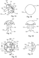
- Humeral component 100 may include four planar surfaces 120, 122, 124, 126 in a concave arrangement in which the planar surfaces converge together as they approach the middle of the articular surface 102, as seen best in FIG. 1A .
- Other examples may include three, five, or more planar surfaces in a concave arrangement. More specifically, one example may include planar surfaces 120, 122, 124. The planar surfaces diverge as they extend away from the middle of the articular surface 102, and intersect the articular surface to establish an articular margin 106 around a perimeter of the humeral component 100.
- the articular margin may be described as scalloped or having indentations.
- planar surfaces 120, 124 intersect along a line 119
- planar surfaces 120, 126 intersect along a line 121
- planar surfaces 120, 122 intersect along a line 123
- planar surfaces 124, 126 intersect along a line 125
- planar surfaces 124, 122 intersect along a line 127.
- the lines 119, 121, 123, 125, 127 may also be referred to as intersections, edges, or internal corners, and may include fillet radii, as best seen in FIG. 1E . Referring to FIG.
- lines 119, 123, 127 intersect at a first point 111; and lines 119, 121, 125 intersect at a second point 113. Lines 123, 121 and 127, 125 also intersect when extended. Line 119 in this example may extend in a superior-inferior direction when the humeral component 100 is implanted.
- the humeral component 100 may have a roughened or porous bone-facing side 104, or undersurface, which rests on the prepared bone of the humerus when the humeral component is implanted. These roughened or porous surfaces assist in bony apposition between the implant and the underlying subcondylar bone encouraging bony ingrowth into the porosity of the bone-facing side once the humeral component is implanted. From this undersurface or bone-facing side 104, at least one anchoring element 128 projects outwardly; the example shown includes three anchoring elements 128, 130, 132. The anchoring elements project into the humeral bone when the humeral component is implanted, and may anchor the humeral component to prevent loosening or micromotion.
- the anchoring elements may be pegs which are round, cruciate, or have fins, or have another cross sectional shape for bone fixation.
- the anchoring elements may include fenestrations. Some of the examples disclosed herein utilize three pegs, but the number of pegs may vary.
- the pegs may be parallel, converging, diverging, or skew.
- the pegs may be smooth, matte, rough, or porous to promote bone cement fixation or bone ingrowth.
- the illustrated anchoring elements 128, 130, 132 are cylindrical and parallel to one another. Anchoring element 128 is longer than anchoring elements 130, 132, and may therefore be suited for implantation in an inferior aspect of the humeral head/neck.
- Humeral component 100 is bilaterally symmetric about a plane through line 119, and may therefore be implanted in right or left shoulders. Humeral component 100 may be implanted so that planar surface 126 covers a superior aspect of the humeral head, planar surface 122 covers an inferior aspect of the humeral head, planar surfaces 120 and 124 cover anterior and posterior portions of the humeral head, anchoring element 128 extends through the inferior aspect of the humeral head and optionally into the humeral neck, and anchoring elements 130, 132 extend into anterior and posterior portions of the humeral head.
- the inferior-most peg may be curved and elongated, forming a stem which extends distally into the diaphysis of the humerus, following the curve of the medial neck of the humerus.
- This inferior peg or stem may be manufactured as one piece with the bearing surface component, or the peg or stem may be modular, supplied in varying thickness and lengths.
- a modular peg may be attached to the bearing portion of the component via a Morse taper, screw-in or other connection mechanism.
- the location of the pegs on the backside of the prosthetic component may project in a more vertical direction.
- This embodiment may be suitable for a surgeon utilizing a subscapularis-preserving surgical technique where the only exposure to the humerus is from the superior direction.
- the prosthesis may be fixed in place with bone cement, or it may have a roughened surface or porous coating on the undersurface for cementless (press-fit) use.
- the entire humeral component 100 may be made of a solid metal piece.
- the prosthesis may be made of another material, such as any of the materials commonly used in orthopaedic joint arthroplasty, such as ceramic, composite, polyethylene or pyrocarbon. Combinations of materials may also be used.
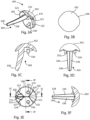
- another humeral component 200 includes an articular surface 202 and a bone-facing side 204 which is opposite to the articular surface.
- Humeral component 200 includes the following features, which may be substantially similar to, or the same as, the corresponding features of humeral component 100: planar surfaces 220, 222, 224, 226; lines 219, 221, 223, 225, 227; points 211, 213; and anchoring elements 228, 230, 232.
- the prosthetic humeral component 200 may have an ellipsoid or ovoid articular surface 202, rather than a spherical articular surface.
- the planar surfaces 220, 222, 224, 226 are in a concave arrangement in which the planar surfaces converge together as they approach the middle of the articular surface 202, as seen best in FIG. 2A .
- Each one of the planar surfaces intersects each other planar surface at an obtuse angle, although right angles and acute angles are also contemplated.
- Fillet radii are present along lines 221, 225 and absent along lines 219, 223, 227.
- the illustrated anchoring elements 228, 230, 232 are cylindrical and parallel to one another. These anchoring elements include bilateral longitudinal grooves 236.
- Anchoring element 228 is longer than anchoring elements 230, 232, and may therefore be suited for implantation in an inferior aspect of the humeral head/neck.
- Humeral component 200 is bilaterally symmetric about a plane through line 219, and may therefore be implanted in right or left shoulders. Humeral component 200 may be implanted so that planar surface 226 covers a superior aspect of the humeral head, planar surface 222 covers an inferior aspect of the humeral head, planar surfaces 220 and 224 cover anterior and posterior portions of the humeral head, anchoring element 228 extends through the inferior aspect of the humeral head and optionally into the humeral neck, and anchoring elements 230, 232 extend into anterior and posterior portions of the humeral head.
- yet another humeral component 300 includes an articular surface 302 and a bone-facing side 304 which is opposite to the articular surface.
- Humeral component 300 includes the following features, which may be substantially similar to, or the same as, the corresponding features of humeral component 100: planar surfaces 320, 322, 324, 326; lines 319, 321, 323, 325, 327; fillet radii; points 311, 313; and anchoring elements 328, 330, 332.
- the prosthetic humeral component 300 may have an ellipsoid or ovoid articular surface 302, rather than a spherical articular surface.
- the planar surfaces 320, 322, 324, 326 are in a concave arrangement in which the planar surfaces converge together as they approach the middle of the articular surface 302, as seen best in FIG. 3A .
- Each one of the planar surfaces intersects each other planar surface at an obtuse angle, although right angles and acute angles are also contemplated.
- the illustrated anchoring elements 330, 332 are cylindrical and parallel to one another.
- Anchoring element 328 is curved outwardly, and is longer than anchoring elements 330, 332, and may therefore be suited for implantation in an inferior aspect of the humeral head/neck.
- Anchoring element 328 also includes four longitudinal grooves 336, which are evenly arranged around anchoring element 328.
- Anchoring element 328 may be described as having a diamond-shaped or star-shaped cross section.
- Humeral component 300 is bilaterally symmetric about a plane through line 319, and may therefore be implanted in right or left shoulders. Humeral component 300 may be implanted so that planar surface 326 covers a superior aspect of the humeral head, planar surface 322 covers an inferior aspect of the humeral head, planar surfaces 320 and 324 cover anterior and posterior portions of the humeral head, anchoring element 328 extends through the inferior aspect of the humeral head and optionally into the humeral neck, and anchoring elements 330, 332 extend into anterior and posterior portions of the humeral head.
- yet another humeral component 400 includes an articular surface 402 and a bone-facing side 404 which is opposite to the articular surface.
- Humeral component 400 includes the following features, which may be substantially similar to, or the same as, the corresponding features of humeral component 100: planar surfaces 420, 422, 424, 426; lines 419, 421, 423, 425, 427; fillet radii; points 411, 413; and anchoring elements 428, 430, 432.
- the prosthetic humeral component 400 may have an ellipsoid or ovoid articular surface 402, rather than a spherical articular surface.
- planar surfaces 420, 422, 424, 426 are in a concave arrangement in which the planar surfaces converge together as they approach the middle of the articular surface 402, as seen best in FIG. 4A .
- Each one of the planar surfaces intersects each other planar surface at an obtuse angle, although right angles and acute angles are also contemplated.
- Planar surface 426 has a smaller area than planar surface 422, and may be described as being indented, or centrally offset, particularly in comparison to planar surface 422.
- Humeral component 400 includes a fourth anchoring element 434.
- the illustrated anchoring elements 428, 430, 432, 434 are cylindrical and parallel to one another. Anchoring elements 428, 430, 432, 434 also include bilateral longitudinal grooves 436.
- Humeral component 400 is bilaterally symmetric about a plane through line 419, and may therefore be implanted in right or left shoulders. Humeral component 400 may be implanted so that planar surface 426 covers a superior aspect of the humeral head, planar surface 422 covers an inferior aspect of the humeral head, planar surfaces 420 and 424 cover anterior and posterior portions of the humeral head, anchoring element 428 extends through the inferior aspect of the humeral head and optionally into the humeral neck, anchoring elements 430, 432 extend into anterior and posterior portions of the humeral head, and anchoring element 434 extends into the superior aspect of the humeral head.
- planar surface 426 faces at least a portion of the rotator cuff, and, because planar surface 426 is indented, a space exists between the rim of planar surface 426 and the rotator cuff. This space provides relief, or room, for the rotator cuff to function without excessively rubbing against the outer portion, or rim, of the humeral component 600, thus reducing the risk of rotator cuff damage.
- yet another humeral component 500 includes an articular surface 502 and a bone-facing side 504 which is opposite to the articular surface.
- Humeral component 500 includes the following features, which may be substantially similar to, or the same as, the corresponding features of humeral component 100: planar surfaces 520, 522, 524, 526; lines 519, 521, 523, 525, 527; fillet radii; points 511, 513; and anchoring elements 528, 530, 532.
- the prosthetic humeral component 500 may have an ellipsoid or ovoid articular surface 502, rather than a spherical articular surface.
- planar surfaces 520, 522, 524, 526 are in a concave arrangement in which the planar surfaces converge together as they approach the middle of the articular surface 502, as seen best in FIG. 5A .
- Each one of the planar surfaces intersects each other planar surface at an obtuse angle, although right angles and acute angles are also contemplated.
- Planar surface 526 has a smaller area than planar surface 522, and may be described as being indented, or centrally offset, particularly in comparison to planar surface 522.
- Humeral component 500 includes a fourth anchoring element 534.
- the illustrated anchoring elements 528, 530, 532, 534 are cylindrical and parallel to one another. Anchoring element 528 may be longer than anchoring elements 530, 532, 534.
- Anchoring elements 528, 530, 532, 534 also include bilateral longitudinal grooves 536.
- Humeral component 500 is bilaterally symmetric about a plane through line 519, and may therefore be implanted in right or left shoulders. Humeral component 500 may be implanted so that planar surface 526 covers a superior aspect of the humeral head, planar surface 522 covers an inferior aspect of the humeral head, planar surfaces 520 and 524 cover anterior and posterior portions of the humeral head, anchoring element 528 extends through the inferior aspect of the humeral head and optionally into the humeral neck, anchoring elements 530, 532 extend into anterior and posterior portions of the humeral head, and anchoring element 534 extends into the superior aspect of the humeral head.
- planar surface 526 faces at least a portion of the rotator cuff, and, because planar surface 526 is indented, a space exists between the rim of planar surface 526 and the rotator cuff. This space provides relief, or room, for the rotator cuff to function, thus reducing the risk of rotator cuff damage.
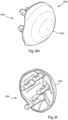
- yet another humeral component 600 includes an articular surface 602 and a bone-facing side 604 which is opposite to the articular surface.
- Humeral component 600 includes the following features, which may be substantially similar to, or the same as, the corresponding features of humeral component 100: planar surfaces 620, 622, 624, 626; lines 619, 621, 623, 625, 627; fillet radii; points 611, 613; and anchoring elements 628, 630, 632.
- the prosthetic humeral component 600 may have an ellipsoid or ovoid articular surface 602, rather than a spherical articular surface.
- planar surfaces 620, 622, 624, 626 are in a concave arrangement in which the planar surfaces converge together as they approach the middle of the articular surface 602, as seen best in FIG. 6A .
- Each one of the planar surfaces intersects each other planar surface at an obtuse angle, although right angles and acute angles are also contemplated.
- Planar surface 626 has a smaller area than planar surface 622, and may be described as being indented, or centrally offset, particularly in comparison to planar surface 622.
- Humeral component 600 includes a fourth anchoring element 634 and a conical surface 674.
- the illustrated anchoring elements 628, 630, 632, 634 are cylindrical and parallel to one another.
- Anchoring element 628 may be longer than anchoring elements 630, 632, 634.
- Anchoring element 634 may be shorter than anchoring elements 628, 630, 632.
- Anchoring elements 628, 630, 632, 634 also include bilateral longitudinal grooves 636.
- the conical surface 674 is present around an outermost portion of the bone-facing side 604, and is best seen in FIG. 6D in the vicinity of the outermost portions of lines 621, 623, 625, 627.
- Humeral component 600 is bilaterally symmetric about a plane through line 619, and may therefore be implanted in right or left shoulders. Humeral component 600 may be implanted so that planar surface 626 covers a superior aspect of the humeral head, planar surface 622 covers an inferior aspect of the humeral head, planar surfaces 620 and 624 cover anterior and posterior portions of the humeral head, anchoring element 628 extends through the inferior aspect of the humeral head and optionally into the humeral neck, anchoring elements 630, 632 extend into anterior and posterior portions of the humeral head, and anchoring element 634 extends into the superior aspect of the humeral head.
- planar surface 626 faces at least a portion of the rotator cuff, and, because planar surface 626 is indented, a space exists between the rim of planar surface 626 and the rotator cuff. This space provides relief, or room, for the rotator cuff to function, thus reducing the risk of rotator cuff damage.
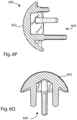
- FIGS. 6F and 6G illustrate humeral component 600 in cross sectional views.
- two additional smaller size humeral components 600', 600'' are superimposed on humeral component 600 to show certain aspects of the design rationale governing the progression from one size to the next.
- the illustrated design rationale may apply to any of the humeral components disclosed herein. If humeral component 600 is referred to as a large size, then humeral component 600' is a medium size, and humeral component 600'' is a small size. However, these small, medium, and large size designations are for the purposes of illustration only. It is understood that a full size range of humeral components may include more than three sizes, including sizes larger than humeral component 600, sizes smaller than humeral component 600", and/or sizes in between those illustrated herein.
- humeral components 600, 600', 600" reveal that the planar surfaces 620, 622, 624, 626; lines 619, 621, 623, 625, 627; fillet radii; points 611, 613; anchoring elements 628, 630, 632, 634, and conical surface 674 are all identical among the three different sizes.
- the same bone preparation - saw cuts, drilled holes, and conical ream - may be performed for all humeral component sizes, and any size humeral component may be implanted onto a particular prepared humerus.
- each articular surface 602, 602', 602' passes through a defined circle 603, which appears as a pair of points 603 in each FIG. 6F and 6G .
- This defined circle 603 may be thought of as a gage circle which has a fixed relationship to the features of the bone-facing side 604.
- the defined circle may lie in the same plane as line 619, for example, or planar surfaces 744, 844 described below.
- the articular surface 602'' of the small humeral component 600" protrudes farther above the circle 603 than do the articular surfaces 602', 602 of the medium and large humeral components 600', 600. Later in this specification, it will be shown that this defined circle 603 may correspond to a depth stop feature on a planar reamer.
- yet another humeral component 700 includes an articular surface 702 and a bone-facing side 704 which is opposite to the articular surface.
- the articular surface is smooth and polished, and may be spherical, elliptical, or ovoid.
- Humeral component 700 may be designed with four overlapping circles of a sphere, or as a hemisphere with a tapered, triangular, flat-bottom socket forming the bone-facing side.
- Humeral component 700 may include four planar surfaces 744, 762, 764, 766 in a concave arrangement in which the planar surfaces 762, 764, 766 converge together as they approach the middle of the articular surface 702 and the planar surface 744, as seen best in FIG. 7A .
- Other examples may include three, five, or more planar surfaces in a concave arrangement. Each one of the planar surfaces intersects each other planar surface at an obtuse angle, although right angles and acute angles are also contemplated.
- Planar surfaces 744, 762 intersect along a line 757
- planar surfaces 744, 764 intersect along a line 759
- planar surfaces 744, 766 intersect along a line 761.
- Planar surfaces 762, 764; 764, 766; and 766, 762 also intersect when extended.
- the lines 757, 759, 761 may also be referred to as intersections, edges, or internal corners, and may include fillet radii, as best seen in FIG. 7D .
- lines 757, 759 intersect at a first point 711; lines 759, 761 intersect at a second point 713; and lines 757, 761 intersect at a third point 715.
- Humeral component 700 also includes a conical surface 774, which is present in the vicinity of the outermost portions of lines 757, 759, 761, as best seen in FIG. 7D .
- the humeral component 700 may have a roughened bone-facing side 704, or undersurface, which rests on the prepared bone of the humerus when the humeral component is implanted. From this undersurface or bone-facing side 704, at least one anchoring element 768 projects outwardly.
- the example shown includes three anchoring elements 768, 770, 772 protruding from planar surfaces 762, 764, 766, respectively.
- the anchoring elements project into the humeral bone when the humeral component is implanted, and may anchor the humeral component to prevent loosening or micromotion.
- the anchoring elements may be pegs which are round, cruciate, or have fins, or have another cross sectional shape for bone fixation.
- the anchoring elements may include fenestrations. Some of the examples disclosed herein utilize three pegs, but the number of pegs may vary.
- the pegs may be parallel, converging, diverging, or skew.
- the pegs may be smooth, matte, rough, or porous to promote bone cement fixation or bone ingrowth.
- the illustrated anchoring elements 768, 770, 772 are cylindrical and parallel to one another.
- Humeral component 700 is bilaterally symmetric about a plane through section line 7F-7F of FIG. 7D , and trilaterally symmetric about an axis normal to planar surface 744. Humeral component 700 may therefore be implanted in right or left shoulders. Humeral component 700 may be implanted so that planar surface 764 covers an inferior aspect of the humeral head, planar surfaces 762 and 766 cover anterior-superior and posterior-superior portions of the humeral head, anchoring element 770 extends through the inferior aspect of the humeral head and optionally into the humeral neck, and anchoring elements 768, 772 extend into anterior and posterior portions of the humeral head. However, due to its trilateral symmetry, humeral component 700 may also be implanted so that planar surface 762 or planar surface 766 covers the inferior aspect of the humeral head instead of planar surface 764.
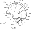
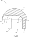
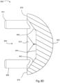
- yet another humeral component 800 includes an articular surface 802 and a bone-facing side 804 which is opposite to the articular surface.
- Humeral component 800 includes the following features, which may be substantially similar to, or the same as, the corresponding features of humeral component 700: planar surfaces 844, 862, 864, 866; lines 857, 859, 861; points 811, 813, 815; conical surface 874; anchoring elements 868, 870, 872.
- the prosthetic humeral component 800 may have an ellipsoid or ovoid articular surface 802, rather than a spherical articular surface.
- planar surfaces 844, 862, 864, 866 are in a concave arrangement in which the planar surfaces 862, 864, 866 converge together as they approach the middle of the articular surface 802 and the planar surface 844, as seen best in FIG. 8A .
- Each one of the planar surfaces intersects each other planar surface at an obtuse angle, although right angles and acute angles are also contemplated.
- Planar surfaces 862, 864 intersect along a line 863
- planar surfaces 864, 866 intersect along a line 865
- planar surfaces 862, 866 intersect along a line 867. No fillet radii are shown in this example.
- the illustrated anchoring elements 868, 870, 872 are cylindrical and parallel to one another.
- Anchoring element 870 also includes four longitudinal grooves 876 which are equally spaced around the anchoring element. Anchoring element 870 may be described as having a cruciate or plus-shaped cross section.
- Humeral component 800 includes a planar surface 878, which is present in the vicinity of the outermost portions of planar surfaces 862, 864, 866, as best seen in FIG. 8A . Planar surface 878 may be parallel to planar surface 844.
- Humeral component 800 is bilaterally symmetric about a plane through section line 8C-8C of FIG. 8B , and trilaterally symmetric about an axis normal to planar surface 844. Humeral component 800 may therefore be implanted in right or left shoulders. Humeral component 800 may be implanted so that planar surface 864 covers an inferior aspect of the humeral head, planar surfaces 862 and 866 cover anterior-superior and posterior-superior portions of the humeral head, anchoring element 870 extends through the inferior aspect of the humeral head and optionally into the humeral neck, and anchoring elements 868, 872 extend into anterior and posterior portions of the humeral head. However, due to its trilateral symmetry, humeral component 800 may also be implanted so that either planar surface 862 or 866 covers the inferior aspect of the humeral head instead of planar surface 864.
- a guide wire or pin 900 and a template 1000 are shown in an operative arrangement.
- the template 1000 may be used to establish the desired orientation of the implanted humeral component relative to the intact proximal humeral anatomy, and may guide insertion of the pin 900 into the humeral head.
- the desired orientation of the humeral component may relate to an axis which is normal to a central portion of the intact articular surface of the humeral head, or parallel to the intact humeral neck axis.
- the pin 900 is a slender elongated shaft 902 which extends between a proximal end 904 and a distal tip 906.
- the shaft 902 may be circular in cross-section as shown, or non-circular in cross-section.
- the proximal end 904 may include a torque connector for connection to a T-handle, drill, or other torque source.
- the distal tip 906 may be threaded, fluted for cutting, pointed, faceted as in a trocar tip, rounded, or blunt.
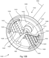
- the template 1000 includes a shaft 1002 which extends between a proximal end 1004 and a distal working portion 1006.
- the proximal end 1004 may include a handle or a coupling.
- the working portion 1006 includes a round perimeter rim 1008 which may be connected to the shaft 1002 by one or more arms 1010.
- the example shown includes bilateral straight arms 1010, 1012 interposed between bilateral bifurcated arms 1014, 1016.
- One or more apertures 1018 may extend between the arms; six apertures 1018 are shown in the example.
- the working portion 1006 has a bone-facing side 1020 and an opposite side 1022.
- the bone-facing side may be concave as shown, convex, or flat.
- the opposite side 1022 may complement the bone-facing side 1020.
- One or more projections 1024 may extend from the rim 1008; three projections 1024, 1026, 1028 are shown, equally spaced around the rim 1008.
- the shaft 1002 may include a central cannulation 1030 which receives the pin 900.
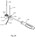
- an alignment guide 1100 is shown in use with the pin 900 and the template 1000 relative to a simplified humeral head 40.
- the alignment guide 1100 may provide additional anatomical referencing beyond that provided by the template 1000, in order to set the desired orientation of the implanted humeral component relative to the intact proximal humeral and forearm anatomy.
- the alignment guide 1100 includes a shaft 1102 which extends between a proximal handle 1104 and a distal working portion 1106. In use, the shaft 1102 is aligned with the patient's forearm in consideration of aligning the pin 900 in the desired rotational anteversion and retroversion of the patient.
- the working portion 1106 includes a plate 1108 and at least one socket 1110 for releasably or permanently coupling to the shaft 1102.
- the plate 1108 may include a humeral shaft extension 1112, an articular bar 1114, and a post 1116.
- the articular bar 1114 may cross the humeral shaft extension 1112 at an oblique angle to form a "T" shape.
- the post 1116 may extend perpendicular to the articular bar 1114 opposite the humeral shaft extension 1112.
- the socket 1110 may be located in the area where the articular bar 1114 crosses the humeral shaft extension 1112.
- the working portion 1106 may include a second socket (not visible in FIG. 28 ) on an opposite side of the plate 1108 from the socket 1110.
- the shaft 1102 may be releasably coupled to either socket to provide configurations suitable for right or left shoulder procedures.
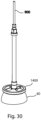
- the planar reamer 1400 may be used to cut a planar bone resection 44 which is perpendicular to the axis of the pin 900 and which may have an outer diameter corresponding to the defined circle 603.
- the bone resection 44 may correspond to planar surfaces 744, 844, or it may correspond to lines 119, 219, 319, 419, 519, 619.
- the planar reamer 1400 includes a shaft 1402 which extends between a proximal end 1404 and a distal working portion 1406.
- the proximal end 1404 may include a handle or a coupling; a torque coupling 1405 is shown for coupling the planar reamer 1400 to a T-handle, drill, or other torque driver.
- the working portion 1406 includes a round perimeter rim 1408 which may be connected to the shaft 1402 by one or more arms 1410.
- the example shown includes bilateral arms 1410, 1412.
- One or more apertures 1418 may extend between the arms; two apertures are shown in the example.
- the working portion 1406 has a bone-facing side 1420 and an opposite side 1422.
- the bone-facing side 1420 is flat.
- Cutting features 1424 are present on the bone-facing side 1420.
- the cutting features 1424 include a series of alternating teeth 1426 and grooves 1428 with concentric circular patterns of crossing grooves 1429, which may be referred to as chip breakers.
- Relief channels 1432 may be included around the outer portion of each arm 1410, 1412 to provide clearance for the tools used to fabricate the cutting features 1424 and/or to delimit an outer diameter of the cutting features.
- a continuous smooth planar surface 1434 extends completely around the perimeter rim 1408 on the bone-facing side 1420, forming a boundary within which all of the cutting features 1424 are contained.
- the surface 1434 may be coplanar with the cutting features 1424, for example the peaks of the teeth 1426 or the valleys of the grooves 1428.
- the surface 1434 may lie above or below the cutting features.
- the surface 1434 functions as a depth stop in use, as will be described later.
- An inner edge 1436 of the surface 1434, excluding any interruption caused by the relief channels 1432, may correspond to the defined circle 603 described above.
- the opposite side 1422 may complement the bone-facing side 1420.
- the shaft 1402 may include a central cannulation 1430 which receives the pin 900.
- planar reamer has a plurality of arms that extend radially from the shaft to the rim like spokes on a wheel.
- This example may or may not have the continuous smooth planar surface that extends completely around the perimeter rim on the bone-facing side.
- This example may have one or more radially extending cutting teeth per arm. Because this example has through openings between the cutting teeth, the bone and articular cartilage fragments are more easily cleared and the reamer is less likely to clog while reaming.
- a conical reamer 1500 includes a shaft 1502 which extends between a proximal end 1504 and a distal working portion 1506.
- the conical reamer 1500 may be used to cut a conical bone resection 74 which corresponds to conical surface 674, 774, 874.
- the proximal end 1504 may include a handle or a coupling; a blunt proximal end is shown.
- the working portion 1506 includes a round perimeter rim 1508 which may be connected to the shaft 1502 by one or more arms 1510.
- the example shown includes a plurality of radially extending arms 1510.
- One or more apertures 1518 may extend between the arms; a plurality of apertures is shown in the example.
- a roughened file-like tissue-cutting surface may also extend the working portion 1506 allowing rasp-like tissue removal.
- the working portion 1506 has a bone-facing side 1520 and an opposite side 1522.
- the bone-facing side includes a conical surface 1512 surrounding a central planar surface 1514 which is perpendicular to the shaft 1502.
- Cutting features 1524 are present on the bone-facing side.
- the cutting features 1524 include a series of radial teeth 1526 on the leading side of each arm 1510 (depending on the direction of rotation, clockwise or counterclockwise).
- a relief channel 1532 may be included between the central planar surface 1514 and the conical surface 1512.
- the planar surface 1514 functions as a depth stop in use, as will be described later.
- the opposite side 1522 may complement the bone-facing side 1520.
- the shaft 1502 may include a central cannulation 1530 which receives the pin 900.
- the proximal humeral bone may be prepared with the use of a cutting guide which rests on the head of the humerus.
- the cutting guide has slots which guide a cutting tool such as an oscillating saw blade to make bone cuts corresponding to the particular design of the undersurface of the humeral prosthesis.
- the humeral cutting guide may be designed to be used by a surgeon utilizing a standard subscapularis tenotomy or lesser tuberosity osteotomy, but may also be adapted to a surgeon utilizing a subscapularis-preserving technique.
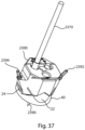
- a cutting guide 1600 may be referred to as a cut and drill guide or as an all in one guide.
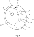
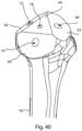
- the cutting guide 1600 may be used to guide a cutting tool, such as a saw blade, to cut four planar bone resections 20, 22, 24, 26 corresponding to planar surfaces 120, 122, 124, 126 of humeral component 100, or the planar surfaces of humeral components 200, 300, 400, 500, 600.
- the cutting guide 1600 may also be used to guide a cutting tool, such as a drill or reamer, to cut bone holes 28, 30, 32 corresponding to anchoring elements 128, 130, 132 of humeral component 100, or the anchoring elements of humeral components 200, 300, 400, 500, 600.
- the cutting guide 1600 may also serve the function of the template 1000.
- the cutting guide 1600 includes a cylindrical body 1608 terminating at one end in a spherical shell or cup 1610.
- the cutting guide 1600 has a bone-facing side 1609 which includes the perimeter rim and concave interior of the spherical cup 1610.
- Three holes 1628, 1630, 1632 extend lengthwise through the cutting guide 1600, corresponding to the relative arrangement of anchoring elements 128, 130, 132 of humeral component 100, or the anchoring elements of humeral components 200, 300, 400, 500, 600.
- a fourth hole may be included in the cutting guide 1600, corresponding to anchoring elements 434, 534, 634 of humeral components 400, 500, 600.
- One or more apertures 1612 may also extend lengthwise through the cutting guide 1600 to provide visualization windows and/or to reduce weight.
- Three apertures 1612, 1613, 1614 are shown in the example, interposed between the holes 1628, 1630, 1632.
- Four slots 1620, 1622, 1624, 1626 extend obliquely through the cutting guide 1600, corresponding to the relative arrangement of planar surfaces 120, 122, 124, 126 of humeral component 100, or the planar surfaces of humeral components 200, 300, 400, 500, 600. It will be appreciated that the number and arrangement of holes and/or slots in the illustrated cutting guide 1600 may be modified to correspond to the number and arrangement of anchoring elements and/or planar surfaces of humeral components 700, 800.
- One or more holes 1616 may extend through the cutting guide 1600 near the rim of the spherical cup 1610 to receive pins to fix the cutting guide 1600 to the humeral head prior to making any bone resections or holes; ten holes 1616, 1646, 1647, 1648, 1649, 1650, 1651, 1652, 1653, 1654 are shown. Holes 1646, 1647, 1648, 1651, 1652, 1653 are all parallel, and holes 1646, 1653; 1647, 1652; and 1648, 1651 are coaxial.
- one or more projections 1656 may extend from the interior of the spherical cup 1610 to engage the articular surface of the humeral head. The example shows three projections 1656, 1657, 1658.
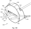
- the cutting guide 1800 may be referred to as an anterior-posterior or A-P cutting guide or as a medial-lateral or M-L cutting guide.
- the cutting guide 1800 may be used to guide a cutting tool, such as a saw blade, to cut two planar bone resections 20, 24 corresponding to planar surfaces 120, 124 of humeral component 100, or the planar surfaces of humeral components 200, 300, 400, 500, 600.
- the cutting guide 1800 includes a body 1808 with a bone-facing side 1809.
- the bone-facing side 1809 includes a planar surface 1844.
- Two slots 1820, 1824 extend obliquely through the cutting guide 1800, corresponding to the relative arrangement of planar surfaces 120, 124 of humeral component 100, or the planar surfaces of humeral components 200, 300, 400, 500, 600.
- the slots 1820, 1824 may intersect at the planar surface 1844.
- One or more holes 1816 may extend through the cutting guide 1800 near opposing apices or ends of the body 1808 to receive fasteners 1890, 1892 to fix the cutting guide 1800 to the humeral head prior to making any bone resections; two converging holes 1816, 1846 are shown.
- a central hole 1818 may extend through the cutting guide 1800 to receive pin 900.
- the cutting guide 1900 may be referred to as an anterior-posterior or A-P cutting guide or as a medial-lateral or M-L cutting guide.
- the cutting guide 1900 may be used to guide a cutting tool, such as a saw blade, to cut two planar bone resections 20, 24 corresponding to planar surfaces 120, 124 of humeral component 100, or the planar surfaces of humeral components 200, 300, 400, 500, 600.
- the cutting guide 1900 includes a shaft 1902 which extends between a proximal handle 1904 and a distal working portion 1906.
- the distal working portion 1906 may be releasably or permanently coupled to the shaft 1902.
- the distal working portion 1906 includes the following features, which may be substantially similar to, or the same as, the corresponding features of the cutting guide 1800: body 1908; bone-facing side 1909; planar surface 1944; slots 1920, 1924; and converging holes 1916, 1946.
- the slots 1920, 1924 extend obliquely through the cutting guide 1900, corresponding to the relative arrangement of planar surfaces 120, 124 of humeral component 100, or the planar surfaces of humeral components 200, 300, 400, 500, 600.
- the slots 1920, 1924 may intersect at the planar surface 1944.
- a central socket or hole 1918 may receive shaft 1902.
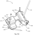
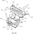
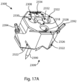
- the cutting guide 2000 may be referred to as a modular anterior-posterior or A-P cutting guide, or as a modular medial-lateral or M-L cutting guide.
- the cutting guide 2000 may be used to guide a cutting tool, such as a saw blade, to cut two planar bone resections 20, 24 corresponding to planar surfaces 120, 124 of humeral component 100, or the planar surfaces of humeral components 200, 300, 400, 500, 600.
- the cutting guide 2000 includes a first body 2008 with a bone-facing side 2009.
- the bone-facing side 2009 includes a planar surface 2044.
- a slot 2020 extends obliquely through the first body 2008, corresponding to the planar surface 120 of humeral component 100, or the planar surface of humeral components 200, 300, 400, 500, 600.
- One or more holes 2016 may extend through the first body 2008 near opposing apices or ends of the body to receive fasteners 2090, 2092 to fix the first body 2008 to the humeral head prior to making any bone resections; two converging holes 2016, 2046 are shown.
- a central hole 2018 may extend through the first body 2008 to receive pin 900.
- the first body 2008 includes a protrusion 2010 which extends from the first body next to the slot 2020.
- the protrusion 2010 may have a rectangular, notched, dovetail, or other cross sectional shape typical of a guide rail.
- a window 2011 or loop extends from the first body opposite the slot 2020.
- the cutting guide 2000 includes a rectangular second body 2012 with a slot 2014 that is complementary to the protrusion 2010 and sized for a clearance fit.
- the slot 2014 slidingly receives the protrusion 2010.
- the second body 2012 includes a fastener 2017 which locks the second body to the protrusion 2010 at a desired location.
- a slot 2024 extends through the second body. When the second body 2012 is operatively assembled to the first body 2008 and the cutting guide 2000 is secured to a humeral head, slot 2024 corresponds to the planar surface 124 of humeral component 100, or the planar surface of humeral components 200, 300, 400, 500, 600.
- One or more holes 2046 may extend through the second body 2012 to receive fasteners 2094, 2096 to fix the second body to the humerus prior to making any bone resections; three diverging holes 2046, 2047, 2048 are shown
- the cutting guide 2100 may be referred to as a modular anterior-posterior or A-P cutting guide or as a modular medial-lateral or M-L cutting guide.
- the cutting guide 2100 may be used to guide a cutting tool, such as a saw blade, to cut two planar bone resections 20, 24 corresponding to planar surfaces 120, 124 of humeral component 100, or the planar surfaces of humeral components 200, 300, 400, 500, 600.
- the cutting guide 2100 includes a shaft 2102 which extends between a proximal handle 2104 and a distal working portion 2106.
- the working portion 2106 includes a first body 2108 and a rectangular second body 2112.
- the first body 2108 includes the following features, which may be substantially similar to, or the same as, the corresponding features of the first body 2008: bone-facing side 2109; planar surface 2144; slot 2120; converging holes 2116, 2146; protrusion 2110; and window 2111 or loop.
- a central socket or hole 2118 may receive shaft 2102.
- the second body 2112 includes the following features, which may be substantially similar to, or the same as, the corresponding features of the second body 2012: slot 2114; fastener 2116; slot 2124; holes 2146, 2147, 2148.
- the cutting guide 2300 may be referred to as a cut and drill guide or as a superior-inferior or S-I cutting guide.
- the cutting guide 2300 may be used to guide a cutting tool, such as a saw blade, to cut two planar bone resections 22, 26 corresponding to planar surfaces 122, 126 of humeral component 100, or the planar surfaces of humeral components 200, 300, 400, 500, 600.
- the cutting guide 2300 may also be used to guide a cutting tool, such as a drill or reamer, to cut bone holes 28, 30, 32 corresponding to anchoring elements 128, 130, 132 of humeral component 100, or the anchoring elements of humeral components 200, 300, 400, 500, 600.
- a cutting tool such as a drill or reamer
- the cutting guide 2300 includes a body 2308 with a bone-facing side 2309.
- the bone-facing side 2309 includes intersecting planar surfaces 2320, 2324.
- Three holes 2328, 2330, 2332 extend lengthwise through the cutting guide 2300, corresponding to the relative arrangement of anchoring elements 128, 130, 132 of humeral component 100, or the anchoring elements of humeral components 200, 300, 400, 500, 600.
- a fourth hole 2334 may be included in the cutting guide 2300, corresponding to anchoring elements 434, 534, 634.
- Two slots 2322, 2326 extend obliquely through the cutting guide 2300, corresponding to the relative arrangement of planar surfaces 122, 126 of humeral component 100, or the planar surfaces of humeral components 200, 300, 400, 500, 600.
- One or more holes 2316 may extend through the cutting guide 2300 near opposing apices or ends of the body 2308 to receive fasteners 2392, 2394 to fix the cutting guide 2300 to the humeral head prior to making any bone resections; two converging holes 2316, 2346 are shown.
- a central hole 2318 may extend through the cutting guide 2300 to receive fastener 2390.
- Fastener 2390 may be countersunk or otherwise recessed into the cutting guide 2300 to avoid occluding the slots 2322, 2326.
- Cutting guide 2300 may be secured by fastener 2390 alone, by fasteners 2392, 2394, by any two of fasteners 2390, 2392, 2394, or by all three fasteners.
- the cutting guide 2400 may be referred to as a cut and drill guide or as a superior-inferior or S-I cutting guide.
- the cutting guide 2400 may be used to guide a cutting tool, such as a saw blade, to cut two planar bone resections 22, 26 corresponding to planar surfaces 122, 126 of humeral component 100, or the planar surfaces of humeral components 200, 300, 400, 500, 600.
- the cutting guide 2400 may also be used to guide a cutting tool, such as a drill or reamer, to cut bone holes 28, 30, 32 corresponding to anchoring elements 128, 130, 132 of humeral component 100, or the anchoring elements of humeral components 200, 300, 400, 500, 600.
- a cutting tool such as a drill or reamer
- the cutting guide 2400 includes a shaft 2402 which extends between a proximal handle 2404 and a distal working portion 2406.
- the distal working portion 2406 may be releasably or permanently coupled to the shaft 2402 by threads or by releasable connection mechanisms.
- the distal working portion 2406 includes the following features, which may be substantially similar to, or the same as, the corresponding features of the cutting guide 2300: body 2408; bone-facing side 2409; intersecting planar surfaces 2420, 2424 (not visible in FIG. 18 ); holes 2428, 2430, 2432, 2434; slots 2422, 2426; and converging holes 2416, 2446.
- the slots 2422, 2426 extend obliquely through the cutting guide 2400, corresponding to the relative arrangement of planar surfaces 122, 126 of humeral component 100, or the planar surfaces of humeral components 200, 300, 400, 500, 600.
- a central socket or hole 2418 may receive shaft 2402.
- the cutting guide 2500 may be referred to as a cut and drill guide.
- the cutting guide 2500 may be used to guide a cutting tool, such as a saw blade, to cut three planar bone resections 62, 64, 66 corresponding to planar surfaces 762, 764, 766 of humeral component 700, or planar surfaces 862, 864, 866 of humeral component 800.
- the cutting guide 2500 may also be used to guide a cutting tool, such as a drill or reamer, to cut bone holes 68, 70, 72 corresponding to anchoring elements 768, 770, 772 of humeral component 700, or anchoring elements 868, 870, 872 of humeral component 800.
- a cutting tool such as a drill or reamer
- the cutting guide 2500 includes a star-shaped body 2508 with a bone-facing side 2509 which includes a planar surface 2544.
- Three holes 2568, 2570, 2572 extend lengthwise through the cutting guide 2500, corresponding to the relative arrangement of anchoring elements 768, 770, 772 of humeral component 700, or anchoring elements 868, 870, 872 of humeral component 800.
- Three slots 2562, 2564, 2566 extend obliquely through the cutting guide 2500, corresponding to the relative arrangement of planar surfaces 762, 764, 766 of humeral component 700, or planar surfaces 862, 864, 866 of humeral component 800.
- a proximal humerus 2 includes a humeral head 4.
- a method of preparing a proximal humerus for implantation of a humeral component 100, 200, 300, 400, 500, 600 may include some or all of the steps of cutting a first planar bone resection 20 to remove a posterior aspect of the humeral head 4; cutting a second planar bone resection 22 to remove an inferior aspect of the humeral head 4; cutting a third planar bone resection 24 to remove an anterior aspect of the humeral head 4; cutting a fourth planar bone resection 26 to remove a superior aspect of the humeral head 4; cutting a first bone hole 28 in an inferior aspect of the humeral head 4; cutting second bone hole 30 in an anterior aspect of the humeral head 4; cutting a third bone hole 32 in a posterior aspect of the humeral head 4; and cutting
- another method of preparing a proximal humerus for implantation of a humeral component 100, 200, 300, 400, 500, 600 may include some or all of the steps of placing the bone-facing side 1609 of the cutting guide 1600 against an intact humeral head 4; aligning the cutting guide 1600 in a desired orientation relative to the intact proximal humeral anatomy so that the projections 1656, 1657, 1658 contact the humeral head; securing the cutting guide 1600 to the proximal humerus by driving at least one pin through any of the holes 1616, 1646, 1647, 1648, 1649, 1650, 1651, 1652, 1653, 1654; cutting four planar bone resections 20, 22, 24, 26 by actuating a saw through each slot 1620, 1622, 1624, 1626; cutting three bone holes 28, 30, 32 by actuating a drill through each hole 1628, 16
- a method of establishing a humeral head axis 6 may include some or all of the steps of placing the bone-facing side 1020 of the template 1000 against an intact humeral head 40, which is shown in simplified form as a hemisphere; aligning the humeral shaft extension 1112 of the alignment guide 1100 with the humeral shaft; aligning the articular bar 1114 of the alignment guide 1100 with the articular margin of the humeral head 40; aligning the template 1000 in a desired orientation relative to the intact proximal humeral anatomy so that the projections 1024, 1026, 1028 contact the humeral head 40, wherein aligning the template 1000 may include aligning the shaft 1002 parallel with the post 1116; driving the pin 900 through the cannulation 1030 and into the humeral head 40; and removing the template 1000 and alignment guide 1100.
- FIG. 29 shows the simplified humeral head 40 with a central bone hole 18 created by driving the pin 900 into the humeral head 40.
- the humeral head axis 6 is the central longitudinal axis of the hole 18, and may be normal to a central portion of the intact articular surface of the humeral head 40, or parallel to the humeral neck axis.
- a method of cutting a planar bone resection 44 may occur after the method of establishing the humeral head axis 6, and may include some or all of the steps of inserting the pin 900 into the cannulation 1430 of the planar reamer 1400; advancing the planar reamer 1400 over the pin 900 to contact the humeral head 40; cutting the planar bone resection 44 by actuating the planar reamer 1400 until the continuous smooth planar surface 1434, or the inner edge 1436 of the surface, contacts the humeral head to stop further bone removal by the planar reamer 1400; and removing the planar reamer.
- FIG. 31 shows the simplified humeral head 40 with the planar bone resection 44 around the bone hole 18. The planar bone resection 44 is normal to the humeral head axis 6.
- FIG. 35 shows the simplified humeral head 40 with the planar bone resections 20, 24.
- Cutting guide 1800 may be replaced by cutting guide 1900 in this method, in which case the shaft 1902 and handle 1904 may be used to push the distal working portion 1906 against the humeral head 40 for added stability during one or more of the steps of securing the cutting guide 1900 to the humeral head 40; removing the pin 900; and cutting two planar bone resections 20, 24.
- another method of cutting anterior and posterior planar bone resections 20, 24 may occur after the method of cutting the planar bone resection 44, and may include some or all of the steps of inserting the pin 900 into the central hole 2018 of the first body 2008 of the cutting guide 2000; advancing the first body 2008 over the pin 900 to contact the humeral head 40, wherein the planar surface 2044 contacts the planar bone resection 44; securing the first body 2008 to the humeral head 40 by driving at least one fastener 2090, 2092 through any of the holes 2016, 2046; removing the pin 900; inserting the protrusion 2010 into the slot 2014 of the second body 2012; advancing the second body 2012 over the protrusion 2010 to contact the humeral head 40; securing the second body 2012 to the protrusion 2010 by actuating the fastener 2017; securing the second body 2012 to the humeral head by driving at least one fastener 20
- FIG. 38 shows the simplified humeral head 40 with the planar bone resections 22, 26 and bone holes 28, 30, 32, 34.
- Cutting guide 2300 may be replaced by cutting guide 2400 in this method, in which case the shaft 2402 and handle 2404 may be used to push the cutting guide 2400 against the humeral head 40 for added stability during one or more of the steps of securing the cutting guide 2300 to the humeral head 40; cutting two planar bone resections 22, 26; and cutting four bone holes 28, 30, 32, 34.
- a method of cutting inferior, antero-superior, and postero-superior planar bone resections 64, 62, 66 and bone holes 70, 68, 72 may occur after the method of cutting the planar bone resection 44, and may include some or all of the steps of inserting the pin 900 into the central hole 2518 of the cutting guide 2500; advancing the cutting guide 2500 over the pin 900 to contact the humeral head 4, wherein the planar surface 2544 contacts the planar bone resection 44; securing the cutting guide 2500 to the humeral head 4 by driving at least one fastener 2590, 2592, 2594 through any of the holes 2546, 2547, 2548; removing the pin 900; cutting three planar bone resections 62, 64, 66 by actuating a saw through holes 2562, 2564, 2566; cutting three bone holes 68, 70, 72 by actuating a
- a method of cutting a conical bone resection 74 may occur after any of the methods of cutting planar bone resections and/or bone holes, and is illustrated as if it occurs after the method of cutting inferior, antero-superior, and postero-superior planar bone resections 64, 62, 66 and bone holes 70, 68, 72.
- the method of cutting the conical bone resection 74 may include some or all of the steps of inserting the pin 900 into the cannulation 1530 of the conical reamer 1500; advancing the conical reamer 1500 over the pin 900 to contact the humeral head 4; cutting the conical bone resection 74 by actuating the conical reamer 1500 until the planar surface 1514 contacts the humeral head to stop further bone removal by the conical reamer 1500, wherein the planar surface 1514 may contact the planar surface 44; and removing the conical reamer.
- FIG. 42 shows the humeral head 4 with the conical bone resection 74 around the humeral head 4.
- humeral component 700 is shown implanted on the humeral head 4 of FIG. 42 .
- the components disclosed herein may be fabricated from metals, alloys, polymers, plastics, ceramics, glasses, composite materials, or combinations thereof, including but not limited to: PEEK, titanium, titanium alloys, commercially pure titanium grade 2, ASTM F67, Nitinol, cobalt chrome, stainless steel, ultra high molecular weight polyethylene (UHMWPE), biocompatible materials, and biodegradable materials, among others. Different materials may be used for different parts. Coatings may be present. Different materials may be used within a single part. Any component disclosed herein may be colored, coded or otherwise marked to make it easier for a user to identify the type and size of the component, the setting, the function(s) of the component, and the like.
- Coupled is defined as connected, although not necessarily directly, and not necessarily mechanically.
- a step of a method or an element of a device that "comprises,” “has,” “includes” or “contains” one or more features, possesses those one or more features, but is not limited to possessing only those one or more features.
- a device or structure that is configured in a certain way is configured in at least that way, but may also be configured in ways that are not listed.
Landscapes
- Health & Medical Sciences (AREA)
- Life Sciences & Earth Sciences (AREA)
- Surgery (AREA)
- Orthopedic Medicine & Surgery (AREA)
- Oral & Maxillofacial Surgery (AREA)
- Engineering & Computer Science (AREA)
- Biomedical Technology (AREA)
- Heart & Thoracic Surgery (AREA)
- Animal Behavior & Ethology (AREA)
- General Health & Medical Sciences (AREA)
- Public Health (AREA)
- Veterinary Medicine (AREA)
- Medical Informatics (AREA)
- Molecular Biology (AREA)
- Dentistry (AREA)
- Nuclear Medicine, Radiotherapy & Molecular Imaging (AREA)
- Transplantation (AREA)
- Vascular Medicine (AREA)
- Cardiology (AREA)
- Physical Education & Sports Medicine (AREA)
- Prostheses (AREA)
Description
- The present disclosure relates to anchoring elements and articular surfaces for human or veterinary implants.
- In total shoulder arthroplasty, a glenoid implant is attached to a prepared glenoid or scapula, and a humeral implant is attached to a prepared humerus. The humeral implant usually includes a convex articular surface, at a proximal end thereof which engages and moves relative to a concave articular surface formed in the glenoid implant, although this arrangement is sometimes reversed so that the humeral implant includes the convex articular surface and the glenoid implant includes the convex articular surface. The ligaments and muscles of the shoulder surround the implants and maintain the humeral implant against the glenoid implant, while at the same time allowing relative movement therebetween.
- Current anatomic prostheses for the proximal humerus generally fall into two types: stemmed prostheses and resurfacing prostheses.
- Stemmed prostheses are quite common. Stemmed prostheses combine a hemispherical head replacement with a stem which extends into the shaft (diaphysis) of the humerus to anchor the prosthesis. Stemmed prostheses often require the removal of the entire hemisphere of humeral head bone, as well as drilling, reaming and/or broaching into the adjacent shaft of the humerus to seat the component. The hemispherical head component and stem are typically solid metal and can be of considerable weight. Stemmed prostheses also frequently require the surgeon to place the humeral head articular bearing surface in a position which is either fixed relative to the shaft of the humerus, or has modular adjustable connection mechanisms allowing partial adjustment between the placement of the hemispherical head component and the stem placed in the shaft of the humerus. This may not always match the actual anatomy of the patient, especially if deformity is present. Although many current prostheses provide for adjustments such as retroversion, offset, or neck-shaft angle, these adjustments are always limited to some degree, or constrained, by the stem to which the prosthetic humeral head is attached.
- Resurfacing prostheses have a hollow hemisphere which rests on top of the humeral bone with a solitary peg or post in the humeral head for anchoring stability. Resurfacing prostheses have the advantage of resting directly on top of the bone of the upper humerus and do not have a stem that extends into the shaft of the humerus. Therefore the surgeon is free to place the prosthesis based on each individual patient's anatomy. Resurfacing prostheses also do not require the removal of the entire humeral head bone; simply the upper articular end is reshaped to accept the prosthesis sitting on top. The prosthesis itself acts as a surface cover, and the volume of bone underneath in the hemisphere remains. This preserves more of the patient's bone stock and if revision surgery is needed, allows for a much simpler re-operation because the shaft has not yet been violated.
- The preservation of bone in the upper humerus with a resurfacing prosthesis may unfortunately become a disadvantage when the surgeon performs a total shoulder arthroplasty. In this operation, the surgeon also places a prosthesis into the glenoid cavity of the scapula. With the bone of the upper humerus still in the way, access to the glenoid may be very difficult and placing the glenoid prosthesis properly can be challenging.
-
US 8313530 B2 discloses a system comprising a plurality of femoral component of different sizes for total knee arthroplasty. The proximal surface of each component size is identical, thereby eliminating the need for a set of differently sized cutting jigs which ultimately simplifies the surgical procedure. -
EP1955677 discloses femoral trochlea prostheses useable in a knee joint. The knee joint includes a patella and a distal femur with a femoral trochlea, or patello-femoral groove. A femoral trochlea prosthesis including a distal tail (36) is disclosed. A femoral trochlea prosthesis including a wing or extension portion is also disclosed. A set of femoral trochlea prostheses including a plurality of prostheses having differing thicknesses is further disclosed. A femoral trochlea prosthesis including a porous medium (102) on various portions of the prosthesis is also disclosed. - While examples of the present technology have been shown and described in detail below, it will be clear to the person skilled in the art that variations, changes and modifications may be made without departing from its scope. As such, that which is set forth in the following description and accompanying drawings is offered by way of illustration only and not as a limitation. The actual scope of the invention is intended to be defined by the following claims.
- Identical reference numerals do not necessarily indicate an identical structure. Rather, the same reference numeral may be used to indicate a similar feature or a feature with similar functionality. Not every feature of each example is labeled in every figure in which that example appears, in order to keep the figures clear. Similar reference numbers (e.g., those that are identical except for the first numeral) are used to indicate similar features in different examples.
-
FIG. 1A is an isometric view of a humeral component;FIG. 1B is a medial view of the humeral component ofFIG. 1A; FIG. 1C is a cross sectional view of the humeral component ofFIG. 1A , taken alongsection line 1C-1C ofFIG. 1E; FIG. 1D is a superior view of the humeral component ofFIG. 1A; FIG. 1E is a lateral view of the humeral component ofFIG. 1A; and FIG. 1F is a cross sectional view of the humeral component ofFIG. 1A , taken alongsection line 1F-1F ofFIG. 1E ; -
FIG. 2A is an isometric view of another humeral component;FIG. 2B is a medial view of the humeral component ofFIG. 2A; FIG. 2C is a cross sectional view of the humeral component ofFIG. 2A , taken alongsection line 2C-2C ofFIG. 2E; FIG. 2D is a superior view of the humeral component ofFIG. 2A; FIG. 2E is a lateral view of the humeral component ofFIG. 2A; and FIG. 2F is a cross sectional view of the humeral component ofFIG. 2A , taken alongsection line 2F-2F ofFIG. 2E ; -
FIG. 3A is an isometric view of yet another humeral component;FIG. 3B is a medial view of the humeral component ofFIG. 3A; FIG. 3C is a cross sectional view of the humeral component ofFIG. 3A , taken alongsection line 3C-3C ofFIG. 3E; FIG. 3D is a superior view of the humeral component ofFIG. 3A; FIG. 3E is a lateral view of the humeral component ofFIG. 3A; and FIG. 3F is a cross sectional view of the humeral component ofFIG. 3A , taken alongsection line 3F-3F ofFIG. 3E ; -
FIG. 4A is an isometric view of yet another humeral component; andFIG. 4B is a lateral view of the humeral component ofFIG. 4A ; -
FIG. 5A is an isometric view of yet another humeral component; andFIG. 5B is a lateral view of the humeral component ofFIG. 5A ; -
FIG. 6A is a superior view of yet another humeral component;FIG. 6B is an anterior view of the humeral component ofFIG. 6A; FIG. 6C is a medial view of the humeral component ofFIG. 6A; FIG. 6D is an isometric view of the humeral component ofFIG. 6A; FIG. 6E is an inferior view of the humeral component ofFIG. 6A ;FIG. 6F is a cross sectional view of the humeral component ofFIG. 6A , taken alongsection line 6F-6F ofFIG. 6C , with superimposed cross sectional profiles of two other size humeral components;FIG. 6G is a cross sectional view of the humeral component ofFIG. 6A , taken alongsection line 6G-6G ofFIG. 6C , with superimposed cross sectional profiles of two other size humeral components;FIG. 6H is a front left perspective view of the humeral component ofFIG. 6A ;FIG. 6I is a back left perspective view of the humeral component ofFIG. 6A ;FIG. 6J is a back view of the humeral component ofFIG. 6A ;FIG. 6K is a front view of the humeral component ofFIG. 6A ;FIG. 6L is a right side view of the humeral component ofFIG. 6A ;FIG. 6M is a left side view of the humeral component ofFIG. 6A ;FIG. 6N is a top view of the humeral component ofFIG. 6A ;FIG. 6O is a bottom view of the humeral component ofFIG. 6A ;FIG. 6P is a cross sectional view of a left portion of the humeral component ofFIG. 6A taken alongline 6P-6P ofFIG. 6J ; andFIG. 6Q is a cross sectional view of a bottom portion of the humeral component ofFIG. 6A taken alongline 6Q-6Q ofFIG. 6J ; -
FIG. 7A is an isometric view of yet another humeral component;FIG. 7B is a superior view of the humeral component ofFIG. 7A; FIG. 7C is an anterior view of the humeral component ofFIG. 7A; FIG. 7D is a lateral view of the humeral component ofFIG. 7A ;FIG. 7E is a cross sectional view of the humeral component ofFIG. 7A , taken alongsection line 7E-7E ofFIG. 7D ; andFIG. 7F is a cross sectional view of the humeral component ofFIG. 7A , taken alongsection line 7F-7F ofFIG. 7D ; -
FIG. 8A is an isometric view of yet another humeral component;FIG. 8B is a lateral view of the humeral component ofFIG. 8A ;FIG. 8C is a cross sectional view of the humeral component ofFIG. 8A , taken alongsection line 8C-8C ofFIG. 8B ; andFIG. 8D is a cross sectional view of the humeral component ofFIG. 8A , taken alongsection line 8D-8D ofFIG. 8B ; -
FIG. 9A is an isometric view of a pin and a template; andFIG. 9B is another isometric view of the template ofFIG. 9A from a different viewpoint; -
FIG. 10A is an isometric view of the pin ofFIG. 9A and a planar reamer; andFIG. 10B is another isometric view of a portion of the pin and planar reamer ofFIG. 10A from a different viewpoint; -
FIG. 11A is an isometric view of a conical reamer; andFIG. 11B is another isometric view of the conical reamer ofFIG. 11A from a different viewpoint; -
FIG. 12A is a top view of a cutting guide;FIG. 12B is a cross sectional view of the cutting guide ofFIG. 12A , taken alongsection line 12B-12B ofFIG. 12A; FIG. 12C is a front view of the cutting guide ofFIG. 12A ;FIG. 12D is a side view of the cutting guide ofFIG. 12A ;FIG. 12E is a bottom view of the cutting guide ofFIG. 12A ; andFIGS. 12F, 12G, 12H ,12I, and FIG. 12J are isometric views of the cutting guide ofFIG. 12A from several different viewpoints; -
FIG. 13A is an isometric view of another cutting guide with the pin ofFIG. 9A and two fasteners; andFIG. 13B is another isometric view of the cutting guide, pin, and fasteners ofFIG. 13A from a different viewpoint; -
FIG. 14 is an isometric view of yet another cutting guide with two fasteners; -
FIG. 15A is an isometric view of yet another cutting guide with the pin ofFIG. 9A and four fasteners; andFIG. 15B is another isometric view of the cutting guide, pin, and fasteners ofFIG. 15A from a different viewpoint; -
FIG. 16 is an isometric view of yet another cutting guide with two fasteners and a saw blade; -
FIG. 17A is an isometric view of yet another cutting guide with three fasteners;FIG. 17B is another isometric view of the cutting guide and fasteners ofFIG. 17A from a different viewpoint; andFIG. 17C is another isometric view of the cutting guide and fasteners ofFIG. 17A with a drill, from the viewpoint ofFIG. 17A ; -
FIG. 18 is an isometric view of yet another cutting guide with two fasteners; -
FIG. 19A is an isometric view of yet another cutting guide; andFIG. 19B is another isometric view of the cutting guide ofFIG. 19A with three fasteners, from a different viewpoint; -
FIG. 20A is an isometric view of an intact proximal humerus along the humeral neck axis; andFIG. 20B is an isometric view of the proximal humerus ofFIG. 20A from a postero-medial viewpoint; -
FIG. 21A is an isometric view of the proximal humerus ofFIG. 20A along the humeral neck axis after a posterior bone resection has been made; andFIG. 21B is an isometric view of the proximal humerus ofFIG. 21A from a postero-medial viewpoint; -
FIG. 22A is an isometric view of the proximal humerus ofFIG. 21A along the humeral neck axis after an inferior bone resection has been made; andFIG. 22B is an isometric view of the proximal humerus ofFIG. 22A from a postero-medial viewpoint; -
FIG. 23A is an isometric view of the proximal humerus ofFIG. 22A along the humeral neck axis after an anterior bone resection has been made; andFIG. 23B is an isometric view of the proximal humerus ofFIG. 23A from a postero-medial viewpoint; -
FIG. 24A is an isometric view of the proximal humerus ofFIG. 23A along the humeral neck axis after a superior bone resection has been made; andFIG. 24B is an isometric view of the proximal humerus ofFIG. 24A from a postero-medial viewpoint; -
FIG. 25A is an isometric view of the proximal humerus ofFIG. 24A along the humeral neck axis after an inferior bone hole has been made; andFIG. 25B is an isometric view of the proximal humerus ofFIG. 25A from a postero-medial viewpoint; -
FIG. 26A is an isometric view of the proximal humerus ofFIG. 25A along the humeral neck axis after anterior and posterior bone holes have been made; andFIG. 26B is an isometric view of the proximal humerus ofFIG. 26A from a postero-medial viewpoint; -
FIG. 27 is an isometric view of the template and pin ofFIG. 9A operatively arranged relative to a simplified humeral head represented by a hemisphere; -
FIG. 28 is an isometric view of the template, pin, and simplified humeral head ofFIG. 27 operatively arranged relative to an alignment guide; -
FIG. 29 is an isometric view of the simplified humeral head ofFIG. 27 after a central pin hole has been made; -
FIG. 30 is an isometric view of the planar reamer and pin ofFIG. 10A operatively arranged relative to the simplified humeral head ofFIG. 29 ; -
FIG. 31 is an isometric view of the simplified humeral head ofFIG. 30 after a planar bone resection has been made perpendicular to the pin hole; -
FIG. 32 is an isometric view of the cutting guide and fasteners ofFIG. 13A and a saw blade operatively arranged relative to the simplified humeral head ofFIG. 31 ; -
FIG. 33 is an isometric view of the cutting guide and fasteners ofFIG. 15A and a saw blade operatively arranged relative to the simplified humeral head ofFIG. 31 ; -
FIG. 34 is an isometric view of the cutting guide and fasteners ofFIG. 16 and a saw blade operatively arranged relative to the simplified humeral head ofFIG. 31 ; -
FIG. 35 is an isometric view of the simplified humeral head ofFIG. 32 after anterior and posterior bone resections have been made; -
FIG. 36 is an isometric view of the cutting guide and fasteners ofFIG. 17A and a saw blade operatively arranged relative to the simplified humeral head ofFIG. 35 ; -
FIG. 37 is an isometric view of the cutting guide, fasteners, and simplified humeral head ofFIG. 36 operatively arranged relative to the drill ofFIG. 17C ; -
FIG. 38 is an isometric view of the simplified humeral head ofFIG. 37 after superior and inferior bone resections and superior, inferior, anterior, and posterior bone holes have been made; -
FIG. 39 is an isometric view of the cutting guide and fasteners ofFIG. 19B operatively arranged with a proximal humerus; -
FIG. 40 is an isometric view of the proximal humerus ofFIG. 39 , after inferior, antero-superior, and postero-superior bone resections and bone holes have been made; -
FIG. 41 is an isometric view of the conical reamer ofFIG. 11A operatively arranged with the proximal humerus ofFIG. 40 ; -
FIG. 42 is an isometric view of the proximal humerus ofFIG. 41 , after a conical resection has been made; and -
FIG. 43 is an isometric view of the proximal humerus ofFIG. 42 , after the humeral component ofFIG. 7 has been implanted. - The present invention provides a humeral arthroplasty system, comprising:
- a small size prosthesis (600") with an articular surface (602'') having a small radius;
- a medium size prosthesis (600') with an articular surface (602') having a medium radius; and
- a large size prosthesis (600) with an articular surface (602) having a large radius;
- wherein the small, medium, and large prosthesis each comprise:
- a bone-facing side (604) which is opposite to the articular surface;
- the bone facing side (604) comprising at least three planar surfaces (620, 622, 624, 626);
- lines (619, 621, 623, 625, 627) at the intersection of the at least three planar surfaces; and
- anchoring elements (628, 630, 632, 634);
- wherein the articular surfaces of the small, medium, and large size prostheses are all spherical, all ellipsoidal, or all ovoid;
- wherein the planar surfaces (620, 622, 624, 626); lines (619, 621, 623, 625, 627); and anchoring elements (628, 630, 632, 634) are all identical among the three different sizes of prosthesis;
- such that the small, medium, and large size prostheses require the same bone preparation;
- Standard medical planes of reference and descriptive terminology are employed in this specification. A sagittal plane divides a body into right and left portions. A mid-sagittal plane divides the body into bilaterally symmetric right and left halves. A coronal plane divides a body into anterior and posterior portions. A transverse plane divides a body into superior and inferior portions. Anterior means toward the front of the body. Posterior means toward the back of the body. Superior means toward the head. Inferior means toward the feet. Medial means toward the midline of the body. Lateral means away from the midline of the body. Axial means toward a central axis of the body. Abaxial means away from a central axis of the body. Ipsilateral means on the same side of the body. Contralateral means on the opposite side of the body. These descriptive terms may be applied to an animate or inanimate body.
- One of the objectives of the present technology is to provide a prosthesis for the articular surface of the proximal humerus that allows for a bone preserving and anatomically accurate surgical operation. The disclosed prosthesis requires several small bone cuts to remove a small amount of bone from the upper humerus, but significantly less than a stemmed prosthesis. However the small amount of bone removed may be just enough to allow improved access to a surgeon who also is placing a glenoid prosthesis, especially if the glenoid prosthesis uses an oblique angle of insertion. The disclosed humeral prosthesis still rests on the surface of the upper humerus and does not extend into the humeral shaft, unless the surgeon chooses to use a longer stemmed example.
- The disclosed humeral prosthesis can be modified by varying the size, angle and relative location of each individual circle of a sphere relative to the other circles. The prosthesis may be altered in discrete regions to adapt the component precisely to cover or avoid certain surrounding anatomical structures, such as the rotator cuff tendon insertions of the teres minor, infraspinatus, supraspinatus, and subscapularis muscles. This cannot be done with a prosthesis designed as a single hemisphere and having an articular margin which lies on a plane.
- Another design, known as a stemless hemiarthroplasty prosthesis, also uses a hemispherical humeral head implant placed on top of the upper humerus after a standard humeral head cut has been made. Though this design does not require the placement of a stem, the solid large metal head is of the same volume and weight as a comparable head used in a stemmed design, but is anchored by a shallow fixation apparatus.
- An objective of the present technology is to disclose a prosthesis for the articular surface of the proximal humerus having overlapping circles of a sphere.
- Another objective of the present technology is to disclose a prosthesis for the articular surface of the proximal humerus having an ellipsoid shape of the humeral articular surface.
- Still another objective of the present technology is to disclose a prosthesis for the articular surface of the proximal humerus having a long stem example of a resurfacing type prosthesis.
- Another objective of the present technology is to disclose a cutting guide instrument used to prepare the bone to seat the humerus prosthesis.
- Advantages of the present technology include the multiple joined circle-of-a-sphere design, which requires less removal of bone than a standard hemiarthroplasty. Due to significantly reduced volume, the metal humeral component weighs significantly less than a standard hemispherical humeral component of corresponding size, but provides nearly equal surface area coverage of the proximal humeral articular surface. The reduced weight of the humeral component may improve shoulder kinematics. The reduced weight of the humeral component may also contribute to improved long-term stability by reducing loosening forces placed on the anchoring elements. Reduced volume of metal may also potentially reduce material costs of manufacturing the implant.
- The humeral canal is not violated during the surgical procedures disclosed herein, reducing blood loss and marrow-fat emboli release into the blood. The canal is also preserved for future stemmed arthroplasty components if revision surgery is ever required. This does not apply in the case of the long stem example.
- The undersurface design resulting from overlapping planar bone cuts provides resistance to rotational forces and is potentially more stable than a single flat cut. This may provide for improved long-term stability of the component. By making multiple oblique cuts through the humeral head surface, a greater proportion of the component will be resting again the strong outer cortical bone of the humerus than a standard hemispherical prosthesis.
- The present design does not require or reference the humeral canal to determine proper location for bone cuts, thus the surgeon is free to position the humeral component to best fit each patient's' individual anatomy. This is even more important in cases where deformity has altered the normal shape of the humerus.
- The articular surface of the humeral prosthesis can be ellipsoid to better match the normal anatomy of the humerus. Current stemmed and resurfacing arthroplasty designs, due to the variable-offset feature of stemmed designs and the bone preparation process of resurfacing designs, include only spherical humeral heads.
- The most inferior circle of the prosthesis extends inferiorly to cover the most medial aspect of the medial humeral neck bone, in order to reduce the incidence of impingement of the medial humerus against a glenoid prosthetic component. Retrieval studies of failed glenoid components have shown that inferior impingement is a significant contributor to glenoid loosening.
- By placing the prosthesis more precisely in a location that better replicates the normal anatomy, motion across the glenohumeral joint may be more smooth and stable, and eccentric forces placed upon the glenoid prosthesis may be reduced.
- The current prosthesis can be finely adjusted by varying the size, angle and relative location of each individual circle of a sphere relative to the other circles. This allows the prosthesis to be altered in discrete regions for clinical purposes.
- Other objectives and advantages of this technology will become apparent from the following description taken in conjunction with the accompanying drawings wherein are set forth, by way of illustration and example, certain embodiments of the technology. The drawings contained herein constitute a part of this specification and include exemplary embodiments of the present technology and illustrate various objects and features thereof.
- Referring to
FIGS. 1A-1F , ahumeral component 100 includes anarticular surface 102 and a bone-facingside 104 which is opposite to the articular surface. - The
humeral component 100 has a smooth, polishedarticular bearing surface 102 which may articulate with a natural glenoid socket or a glenoid prosthetic component. The glenoid component may be polyethylene or another biocompatible material. - The prosthetic humeral component may be designed as multiple overlapping circles of a sphere, where the sphere forms the
articular surface 102. A "circle of a sphere" is a circle defined by the intersection of a sphere and a plane. If the plane contains the center of the sphere, then the circle is called a "great circle"; otherwise, it is a "small circle." A "spherical cap" is a three-dimensional portion of a sphere cut off by an intersecting plane. If the plane passes through the center of the sphere, the spherical cap is called a "hemisphere." If the height of the spherical cap is less than the radius of the sphere, the spherical cap is called a "minor spherical cap." If the height of the spherical cap is greater than the radius of the sphere, the spherical cap is called a "major spherical cap." In this specification, any reference to a circle of a sphere is also a reference to the corresponding spherical cap, and any reference to a spherical cap is also a reference to the corresponding circle of the sphere. - Together these overlapping circles of a sphere, and corresponding spherical caps, form an articular surface which is nearly hemispherical, or partly spherical, but with significantly less volume of material than a solid hemisphere due to the multiple planar surfaces on the
bone facing side 104, which in a solid hemisphere would be flat. The articular surface area created by the overlapping circles of a sphere nearly covers the native articular surface of the proximal humerus. Referring toFIG. 1A , each one of the planar surfaces corresponds to one of the overlapping circles of a sphere or spherical caps. All of the spherical surfaces are co-radial; they share the same spherical center and all spherical radii are equal, so that thearticular surface 102 is an uninterrupted spherical surface. Some examples of the present technology utilize four overlapping circles of a sphere, but other examples may have three, five or more overlapping circles of a sphere. - In an alternate version of the technology, the prosthetic
humeral component 100 may have an ellipsoid or ovoidarticular surface 102, rather than a spherical articular surface. The circles of an ellipsoid or ovoid, and the corresponding caps, may be overlapped to create the same effect of covering a similar amount of surface area with a reduced volume of material. The ellipsoid or ovoid articular surface has a first radius (or first diameter) in a first plane or along a first axis which is dimensionally different from a second radius (or second diameter) in a second plane or along a second axis. The first radius may be larger or smaller than the second radius. Referring toFIGS. 1C, 1E, and 1F , the radius ofarticular surface 102 inFIG. 1C may be dimensionally different from the radius ofarticular surface 102 inFIG. 1F when thearticular surface 102 is ellipsoid or ovoid instead of spherical. For example, an ellipsoid or ovoid articular surface may have a larger diameter along the superior-inferior axis in the coronal plane than in the transverse plane, or vice versa. The increased radius of curvature of an ellipsoid or ovoid bearing surface in a given direction may reduce the constraint of the humeral head within the glenohumeral joint in that direction. This reduced constraint may result in reduced eccentric forces applied to the bearing surface and reduced risk of implant loosening. The increased radius of curvature may be oriented relative to the prevailing direction of articulation of a given joint, or relative to an articulation direction in which impingement, loosening, or other stress-related effects are known to occur. These ellipsoid or ovoid shapes may also be narrower at the superior end and broader at the inferior end. The ellipsoid or ovoid shape may better replicate the normal articular surface of the humeral head, better replicating the kinematics of the shoulder during articulation, and better matching the morphology of the natural articulating surface, allowing for better fit and transition between the implant and the bone, at least in some patients. - Humeral components according to the present technology may also be designed as a hemisphere, spherical cap, ellipsoid cap, or ovoid cap with a tapered polygonal socket forming the bone-facing side. The tapered polygonal socket may be designed by extruding a polygonal shape from the flat side of the hemisphere or cap toward the articular surface while tapering the sides of the polygonal shape inward. The polygonal shape may be a triangle, square, rectangle, pentagon, or other polygonal shape, and may be regular or irregular, and may be symmetrically or asymmetrically disposed relative to the center of the hemisphere or cap. The sides of the polygonal shape may all have the same taper angle, although one or more sides may have a different taper angle. It can be appreciated that the bone-facing
side 104 ofhumeral component 100 may be designed as a tapered rectangular socket, and similarly forhumeral components -
Humeral component 100 may include fourplanar surfaces articular surface 102, as seen best inFIG. 1A . Other examples may include three, five, or more planar surfaces in a concave arrangement. More specifically, one example may includeplanar surfaces articular surface 102, and intersect the articular surface to establish anarticular margin 106 around a perimeter of thehumeral component 100. The articular margin may be described as scalloped or having indentations. Each one of the planar surfaces intersects each other planar surface at an obtuse angle, although right angles and acute angles are also contemplated. Planar surfaces 120, 124 intersect along aline 119,planar surfaces line 121,planar surfaces line 123,planar surfaces line 125, andplanar surfaces line 127. Thelines FIG. 1E . Referring toFIG. 1E ,lines first point 111; andlines second point 113.Lines Line 119 in this example may extend in a superior-inferior direction when thehumeral component 100 is implanted. - The
humeral component 100 may have a roughened or porous bone-facingside 104, or undersurface, which rests on the prepared bone of the humerus when the humeral component is implanted. These roughened or porous surfaces assist in bony apposition between the implant and the underlying subcondylar bone encouraging bony ingrowth into the porosity of the bone-facing side once the humeral component is implanted. From this undersurface or bone-facingside 104, at least oneanchoring element 128 projects outwardly; the example shown includes three anchoringelements anchoring elements element 128 is longer than anchoringelements -
Humeral component 100 is bilaterally symmetric about a plane throughline 119, and may therefore be implanted in right or left shoulders.Humeral component 100 may be implanted so thatplanar surface 126 covers a superior aspect of the humeral head,planar surface 122 covers an inferior aspect of the humeral head,planar surfaces element 128 extends through the inferior aspect of the humeral head and optionally into the humeral neck, and anchoringelements - In one example, the inferior-most peg may be curved and elongated, forming a stem which extends distally into the diaphysis of the humerus, following the curve of the medial neck of the humerus. This inferior peg or stem may be manufactured as one piece with the bearing surface component, or the peg or stem may be modular, supplied in varying thickness and lengths. A modular peg may be attached to the bearing portion of the component via a Morse taper, screw-in or other connection mechanism.
- In another embodiment, the location of the pegs on the backside of the prosthetic component may project in a more vertical direction. This embodiment may be suitable for a surgeon utilizing a subscapularis-preserving surgical technique where the only exposure to the humerus is from the superior direction.
- The prosthesis may be fixed in place with bone cement, or it may have a roughened surface or porous coating on the undersurface for cementless (press-fit) use.
- The entire
humeral component 100 may be made of a solid metal piece. In other examples, the prosthesis may be made of another material, such as any of the materials commonly used in orthopaedic joint arthroplasty, such as ceramic, composite, polyethylene or pyrocarbon. Combinations of materials may also be used. - Referring to
FIGS. 2A-2F , anotherhumeral component 200 includes anarticular surface 202 and a bone-facingside 204 which is opposite to the articular surface.Humeral component 200 includes the following features, which may be substantially similar to, or the same as, the corresponding features of humeral component 100:planar surfaces lines points elements humeral component 200 may have an ellipsoid or ovoidarticular surface 202, rather than a spherical articular surface. Theplanar surfaces articular surface 202, as seen best inFIG. 2A . Each one of the planar surfaces intersects each other planar surface at an obtuse angle, although right angles and acute angles are also contemplated. Fillet radii are present alonglines lines anchoring elements longitudinal grooves 236. Anchoringelement 228 is longer than anchoringelements -
Humeral component 200 is bilaterally symmetric about a plane throughline 219, and may therefore be implanted in right or left shoulders.Humeral component 200 may be implanted so thatplanar surface 226 covers a superior aspect of the humeral head,planar surface 222 covers an inferior aspect of the humeral head,planar surfaces element 228 extends through the inferior aspect of the humeral head and optionally into the humeral neck, and anchoringelements - Referring to
FIGS. 3A-3F , yet anotherhumeral component 300 includes anarticular surface 302 and a bone-facingside 304 which is opposite to the articular surface.Humeral component 300 includes the following features, which may be substantially similar to, or the same as, the corresponding features of humeral component 100:planar surfaces lines points elements humeral component 300 may have an ellipsoid or ovoidarticular surface 302, rather than a spherical articular surface. Theplanar surfaces articular surface 302, as seen best inFIG. 3A . Each one of the planar surfaces intersects each other planar surface at an obtuse angle, although right angles and acute angles are also contemplated. The illustratedanchoring elements element 328 is curved outwardly, and is longer than anchoringelements element 328 also includes fourlongitudinal grooves 336, which are evenly arranged around anchoringelement 328. Anchoringelement 328 may be described as having a diamond-shaped or star-shaped cross section. -
Humeral component 300 is bilaterally symmetric about a plane throughline 319, and may therefore be implanted in right or left shoulders.Humeral component 300 may be implanted so thatplanar surface 326 covers a superior aspect of the humeral head,planar surface 322 covers an inferior aspect of the humeral head,planar surfaces element 328 extends through the inferior aspect of the humeral head and optionally into the humeral neck, and anchoringelements - Referring to
FIGS. 4A-4B , yet anotherhumeral component 400 includes anarticular surface 402 and a bone-facingside 404 which is opposite to the articular surface.Humeral component 400 includes the following features, which may be substantially similar to, or the same as, the corresponding features of humeral component 100:planar surfaces lines points elements humeral component 400 may have an ellipsoid or ovoidarticular surface 402, rather than a spherical articular surface. Theplanar surfaces articular surface 402, as seen best inFIG. 4A . Each one of the planar surfaces intersects each other planar surface at an obtuse angle, although right angles and acute angles are also contemplated.Planar surface 426 has a smaller area thanplanar surface 422, and may be described as being indented, or centrally offset, particularly in comparison toplanar surface 422.Humeral component 400 includes afourth anchoring element 434. The illustratedanchoring elements elements longitudinal grooves 436. -
Humeral component 400 is bilaterally symmetric about a plane throughline 419, and may therefore be implanted in right or left shoulders.Humeral component 400 may be implanted so thatplanar surface 426 covers a superior aspect of the humeral head,planar surface 422 covers an inferior aspect of the humeral head,planar surfaces element 428 extends through the inferior aspect of the humeral head and optionally into the humeral neck, anchoringelements element 434 extends into the superior aspect of the humeral head. The outer portion, or rim, ofplanar surface 426 faces at least a portion of the rotator cuff, and, becauseplanar surface 426 is indented, a space exists between the rim ofplanar surface 426 and the rotator cuff. This space provides relief, or room, for the rotator cuff to function without excessively rubbing against the outer portion, or rim, of thehumeral component 600, thus reducing the risk of rotator cuff damage. - Referring to
FIGS. 5A-5B , yet anotherhumeral component 500 includes anarticular surface 502 and a bone-facingside 504 which is opposite to the articular surface.Humeral component 500 includes the following features, which may be substantially similar to, or the same as, the corresponding features of humeral component 100:planar surfaces lines points elements humeral component 500 may have an ellipsoid or ovoidarticular surface 502, rather than a spherical articular surface. Theplanar surfaces articular surface 502, as seen best inFIG. 5A . Each one of the planar surfaces intersects each other planar surface at an obtuse angle, although right angles and acute angles are also contemplated.Planar surface 526 has a smaller area thanplanar surface 522, and may be described as being indented, or centrally offset, particularly in comparison toplanar surface 522.Humeral component 500 includes afourth anchoring element 534. The illustratedanchoring elements element 528 may be longer than anchoringelements elements longitudinal grooves 536. -
Humeral component 500 is bilaterally symmetric about a plane throughline 519, and may therefore be implanted in right or left shoulders.Humeral component 500 may be implanted so thatplanar surface 526 covers a superior aspect of the humeral head,planar surface 522 covers an inferior aspect of the humeral head,planar surfaces element 528 extends through the inferior aspect of the humeral head and optionally into the humeral neck, anchoringelements element 534 extends into the superior aspect of the humeral head. The outer portion, or rim, ofplanar surface 526 faces at least a portion of the rotator cuff, and, becauseplanar surface 526 is indented, a space exists between the rim ofplanar surface 526 and the rotator cuff. This space provides relief, or room, for the rotator cuff to function, thus reducing the risk of rotator cuff damage. - Referring to
FIGS. 6A-6Q , yet anotherhumeral component 600 includes anarticular surface 602 and a bone-facingside 604 which is opposite to the articular surface.Humeral component 600 includes the following features, which may be substantially similar to, or the same as, the corresponding features of humeral component 100:planar surfaces lines elements humeral component 600 may have an ellipsoid or ovoidarticular surface 602, rather than a spherical articular surface. Theplanar surfaces articular surface 602, as seen best inFIG. 6A . Each one of the planar surfaces intersects each other planar surface at an obtuse angle, although right angles and acute angles are also contemplated.Planar surface 626 has a smaller area thanplanar surface 622, and may be described as being indented, or centrally offset, particularly in comparison toplanar surface 622.Humeral component 600 includes afourth anchoring element 634 and aconical surface 674. The illustratedanchoring elements element 628 may be longer than anchoringelements element 634 may be shorter than anchoringelements elements longitudinal grooves 636. Theconical surface 674 is present around an outermost portion of the bone-facingside 604, and is best seen inFIG. 6D in the vicinity of the outermost portions oflines -
Humeral component 600 is bilaterally symmetric about a plane throughline 619, and may therefore be implanted in right or left shoulders.Humeral component 600 may be implanted so thatplanar surface 626 covers a superior aspect of the humeral head,planar surface 622 covers an inferior aspect of the humeral head,planar surfaces element 628 extends through the inferior aspect of the humeral head and optionally into the humeral neck, anchoringelements element 634 extends into the superior aspect of the humeral head. The outer portion, or rim, ofplanar surface 626 faces at least a portion of the rotator cuff, and, becauseplanar surface 626 is indented, a space exists between the rim ofplanar surface 626 and the rotator cuff. This space provides relief, or room, for the rotator cuff to function, thus reducing the risk of rotator cuff damage. -
FIGS. 6F and 6G illustratehumeral component 600 in cross sectional views. In each view, two additional smaller size humeral components 600', 600'' are superimposed onhumeral component 600 to show certain aspects of the design rationale governing the progression from one size to the next. The illustrated design rationale may apply to any of the humeral components disclosed herein. Ifhumeral component 600 is referred to as a large size, then humeral component 600' is a medium size, and humeral component 600'' is a small size. However, these small, medium, and large size designations are for the purposes of illustration only. It is understood that a full size range of humeral components may include more than three sizes, including sizes larger thanhumeral component 600, sizes smaller thanhumeral component 600", and/or sizes in between those illustrated herein. - The superimposed cross sections of
humeral components planar surfaces lines elements conical surface 674 are all identical among the three different sizes. In other words, the same bone preparation - saw cuts, drilled holes, and conical ream - may be performed for all humeral component sizes, and any size humeral component may be implanted onto a particular prepared humerus. - The superimposed cross sections of
humeral components 600, 600', 600'' also show that the variousarticular surfaces 602, 602', 602' are neither concentric nor tangent. Instead, eacharticular surface 602, 602', 602'' passes through a definedcircle 603, which appears as a pair ofpoints 603 in eachFIG. 6F and 6G . This definedcircle 603 may be thought of as a gage circle which has a fixed relationship to the features of the bone-facingside 604. The defined circle may lie in the same plane asline 619, for example, orplanar surfaces humeral component 600" protrudes farther above thecircle 603 than do thearticular surfaces 602', 602 of the medium and largehumeral components 600', 600. Later in this specification, it will be shown that this definedcircle 603 may correspond to a depth stop feature on a planar reamer. - Referring to
FIGS. 7A-7F , yet anotherhumeral component 700 includes anarticular surface 702 and a bone-facingside 704 which is opposite to the articular surface. The articular surface is smooth and polished, and may be spherical, elliptical, or ovoid.Humeral component 700 may be designed with four overlapping circles of a sphere, or as a hemisphere with a tapered, triangular, flat-bottom socket forming the bone-facing side. -
Humeral component 700 may include fourplanar surfaces planar surfaces articular surface 702 and theplanar surface 744, as seen best inFIG. 7A . Other examples may include three, five, or more planar surfaces in a concave arrangement. Each one of the planar surfaces intersects each other planar surface at an obtuse angle, although right angles and acute angles are also contemplated. Planar surfaces 744, 762 intersect along aline 757,planar surfaces line 759, andplanar surfaces lines FIG. 7D . Referring toFIG. 7D ,lines first point 711;lines 759, 761 intersect at asecond point 713; andlines 757, 761 intersect at athird point 715.Humeral component 700 also includes aconical surface 774, which is present in the vicinity of the outermost portions oflines FIG. 7D . - The
humeral component 700 may have a roughened bone-facingside 704, or undersurface, which rests on the prepared bone of the humerus when the humeral component is implanted. From this undersurface or bone-facingside 704, at least oneanchoring element 768 projects outwardly. The example shown includes three anchoringelements planar surfaces anchoring elements -
Humeral component 700 is bilaterally symmetric about a plane throughsection line 7F-7F ofFIG. 7D , and trilaterally symmetric about an axis normal toplanar surface 744.Humeral component 700 may therefore be implanted in right or left shoulders.Humeral component 700 may be implanted so thatplanar surface 764 covers an inferior aspect of the humeral head,planar surfaces element 770 extends through the inferior aspect of the humeral head and optionally into the humeral neck, and anchoringelements humeral component 700 may also be implanted so thatplanar surface 762 orplanar surface 766 covers the inferior aspect of the humeral head instead ofplanar surface 764. - Referring to
FIGS. 8A-8D , yet anotherhumeral component 800 includes anarticular surface 802 and a bone-facingside 804 which is opposite to the articular surface. -
Humeral component 800 includes the following features, which may be substantially similar to, or the same as, the corresponding features of humeral component 700:planar surfaces lines points conical surface 874; anchoringelements humeral component 800 may have an ellipsoid or ovoidarticular surface 802, rather than a spherical articular surface. Theplanar surfaces planar surfaces articular surface 802 and theplanar surface 844, as seen best inFIG. 8A . Each one of the planar surfaces intersects each other planar surface at an obtuse angle, although right angles and acute angles are also contemplated. Planar surfaces 862, 864 intersect along aline 863,planar surfaces line 865, andplanar surfaces line 867. No fillet radii are shown in this example. The illustratedanchoring elements element 870 also includes fourlongitudinal grooves 876 which are equally spaced around the anchoring element. Anchoringelement 870 may be described as having a cruciate or plus-shaped cross section.Humeral component 800 includes aplanar surface 878, which is present in the vicinity of the outermost portions ofplanar surfaces FIG. 8A .Planar surface 878 may be parallel toplanar surface 844. -
Humeral component 800 is bilaterally symmetric about a plane throughsection line 8C-8C ofFIG. 8B , and trilaterally symmetric about an axis normal toplanar surface 844.Humeral component 800 may therefore be implanted in right or left shoulders.Humeral component 800 may be implanted so thatplanar surface 864 covers an inferior aspect of the humeral head,planar surfaces element 870 extends through the inferior aspect of the humeral head and optionally into the humeral neck, and anchoringelements humeral component 800 may also be implanted so that eitherplanar surface planar surface 864. - Referring to
FIG. 9A , a guide wire orpin 900 and atemplate 1000 are shown in an operative arrangement. Thetemplate 1000 may be used to establish the desired orientation of the implanted humeral component relative to the intact proximal humeral anatomy, and may guide insertion of thepin 900 into the humeral head. The desired orientation of the humeral component may relate to an axis which is normal to a central portion of the intact articular surface of the humeral head, or parallel to the intact humeral neck axis. - The
pin 900 is a slenderelongated shaft 902 which extends between aproximal end 904 and adistal tip 906. Theshaft 902 may be circular in cross-section as shown, or non-circular in cross-section. Theproximal end 904 may include a torque connector for connection to a T-handle, drill, or other torque source. Thedistal tip 906 may be threaded, fluted for cutting, pointed, faceted as in a trocar tip, rounded, or blunt. - Referring to
FIGS. 9A-9B , thetemplate 1000 includes ashaft 1002 which extends between aproximal end 1004 and adistal working portion 1006. Theproximal end 1004 may include a handle or a coupling. The workingportion 1006 includes around perimeter rim 1008 which may be connected to theshaft 1002 by one ormore arms 1010. The example shown includes bilateralstraight arms bifurcated arms more apertures 1018 may extend between the arms; sixapertures 1018 are shown in the example. The workingportion 1006 has a bone-facingside 1020 and anopposite side 1022. The bone-facing side may be concave as shown, convex, or flat. Theopposite side 1022 may complement the bone-facingside 1020. One ormore projections 1024 may extend from therim 1008; threeprojections rim 1008. Theshaft 1002 may include acentral cannulation 1030 which receives thepin 900. - Referring to
FIG. 28 , analignment guide 1100 is shown in use with thepin 900 and thetemplate 1000 relative to a simplifiedhumeral head 40. Thealignment guide 1100 may provide additional anatomical referencing beyond that provided by thetemplate 1000, in order to set the desired orientation of the implanted humeral component relative to the intact proximal humeral and forearm anatomy. - The
alignment guide 1100 includes ashaft 1102 which extends between aproximal handle 1104 and adistal working portion 1106. In use, theshaft 1102 is aligned with the patient's forearm in consideration of aligning thepin 900 in the desired rotational anteversion and retroversion of the patient. The workingportion 1106 includes aplate 1108 and at least onesocket 1110 for releasably or permanently coupling to theshaft 1102. Theplate 1108 may include ahumeral shaft extension 1112, anarticular bar 1114, and apost 1116. Thearticular bar 1114 may cross thehumeral shaft extension 1112 at an oblique angle to form a "T" shape. Thepost 1116 may extend perpendicular to thearticular bar 1114 opposite thehumeral shaft extension 1112. Thesocket 1110 may be located in the area where thearticular bar 1114 crosses thehumeral shaft extension 1112. The workingportion 1106 may include a second socket (not visible inFIG. 28 ) on an opposite side of theplate 1108 from thesocket 1110. Theshaft 1102 may be releasably coupled to either socket to provide configurations suitable for right or left shoulder procedures. - Referring to
FIGS. 10A-10B , thepin 900 and aplanar reamer 1400 are shown in an operative arrangement. Theplanar reamer 1400 may be used to cut aplanar bone resection 44 which is perpendicular to the axis of thepin 900 and which may have an outer diameter corresponding to the definedcircle 603. Thebone resection 44 may correspond toplanar surfaces lines - The
planar reamer 1400 includes ashaft 1402 which extends between aproximal end 1404 and adistal working portion 1406. Theproximal end 1404 may include a handle or a coupling; atorque coupling 1405 is shown for coupling theplanar reamer 1400 to a T-handle, drill, or other torque driver. The workingportion 1406 includes around perimeter rim 1408 which may be connected to theshaft 1402 by one ormore arms 1410. The example shown includesbilateral arms more apertures 1418 may extend between the arms; two apertures are shown in the example. The workingportion 1406 has a bone-facingside 1420 and anopposite side 1422. The bone-facingside 1420 is flat. Cutting features 1424 are present on the bone-facingside 1420. In this example, the cutting features 1424 include a series of alternatingteeth 1426 andgrooves 1428 with concentric circular patterns of crossinggrooves 1429, which may be referred to as chip breakers.Relief channels 1432 may be included around the outer portion of eacharm planar surface 1434 extends completely around theperimeter rim 1408 on the bone-facingside 1420, forming a boundary within which all of the cutting features 1424 are contained. Thesurface 1434 may be coplanar with the cutting features 1424, for example the peaks of theteeth 1426 or the valleys of thegrooves 1428. Alternatively, thesurface 1434 may lie above or below the cutting features. Thesurface 1434 functions as a depth stop in use, as will be described later. Aninner edge 1436 of thesurface 1434, excluding any interruption caused by therelief channels 1432, may correspond to the definedcircle 603 described above. Theopposite side 1422 may complement the bone-facingside 1420. Theshaft 1402 may include acentral cannulation 1430 which receives thepin 900. - Another example of a planar reamer has a plurality of arms that extend radially from the shaft to the rim like spokes on a wheel. This example may or may not have the continuous smooth planar surface that extends completely around the perimeter rim on the bone-facing side. This example may have one or more radially extending cutting teeth per arm. Because this example has through openings between the cutting teeth, the bone and articular cartilage fragments are more easily cleared and the reamer is less likely to clog while reaming.
- Referring to
FIGS. 11A-11B , aconical reamer 1500 includes ashaft 1502 which extends between aproximal end 1504 and adistal working portion 1506. Theconical reamer 1500 may be used to cut aconical bone resection 74 which corresponds toconical surface proximal end 1504 may include a handle or a coupling; a blunt proximal end is shown. The workingportion 1506 includes around perimeter rim 1508 which may be connected to theshaft 1502 by one ormore arms 1510. The example shown includes a plurality of radially extendingarms 1510. One ormore apertures 1518 may extend between the arms; a plurality of apertures is shown in the example. However, a roughened file-like tissue-cutting surface may also extend the workingportion 1506 allowing rasp-like tissue removal. The workingportion 1506 has a bone-facingside 1520 and anopposite side 1522. The bone-facing side includes aconical surface 1512 surrounding a centralplanar surface 1514 which is perpendicular to theshaft 1502. Cutting features 1524 are present on the bone-facing side. In this example, the cutting features 1524 include a series ofradial teeth 1526 on the leading side of each arm 1510 (depending on the direction of rotation, clockwise or counterclockwise). Arelief channel 1532 may be included between the centralplanar surface 1514 and theconical surface 1512. Theplanar surface 1514 functions as a depth stop in use, as will be described later. Theopposite side 1522 may complement the bone-facingside 1520. Theshaft 1502 may include acentral cannulation 1530 which receives thepin 900. - Specific preparations of the proximal humeral bone surface are disclosed in order to accommodate the multi-planar undersurfaces of the prosthetic components so the undersurfaces rests flush against the bone. The proximal humeral bone may be prepared with the use of a cutting guide which rests on the head of the humerus. The cutting guide has slots which guide a cutting tool such as an oscillating saw blade to make bone cuts corresponding to the particular design of the undersurface of the humeral prosthesis. The humeral cutting guide may be designed to be used by a surgeon utilizing a standard subscapularis tenotomy or lesser tuberosity osteotomy, but may also be adapted to a surgeon utilizing a subscapularis-preserving technique. Various cutting guides will now be described.
- Referring to
FIGS. 12A-12J , a cuttingguide 1600 may be referred to as a cut and drill guide or as an all in one guide. The cuttingguide 1600 may be used to guide a cutting tool, such as a saw blade, to cut fourplanar bone resections planar surfaces humeral component 100, or the planar surfaces ofhumeral components guide 1600 may also be used to guide a cutting tool, such as a drill or reamer, to cut bone holes 28, 30, 32 corresponding to anchoringelements humeral component 100, or the anchoring elements ofhumeral components guide 1600 may also serve the function of thetemplate 1000. - The cutting
guide 1600 includes acylindrical body 1608 terminating at one end in a spherical shell orcup 1610. The cuttingguide 1600 has a bone-facingside 1609 which includes the perimeter rim and concave interior of thespherical cup 1610. Threeholes guide 1600, corresponding to the relative arrangement of anchoringelements humeral component 100, or the anchoring elements ofhumeral components cutting guide 1600, corresponding to anchoringelements humeral components more apertures 1612 may also extend lengthwise through the cuttingguide 1600 to provide visualization windows and/or to reduce weight. Threeapertures holes slots guide 1600, corresponding to the relative arrangement ofplanar surfaces humeral component 100, or the planar surfaces ofhumeral components cutting guide 1600 may be modified to correspond to the number and arrangement of anchoring elements and/or planar surfaces ofhumeral components more holes 1616 may extend through the cuttingguide 1600 near the rim of thespherical cup 1610 to receive pins to fix thecutting guide 1600 to the humeral head prior to making any bone resections or holes; tenholes Holes FIG. 12E , one ormore projections 1656 may extend from the interior of thespherical cup 1610 to engage the articular surface of the humeral head. The example shows threeprojections - Referring to
FIGS. 13A-13B , a cuttingguide 1800, thepin 900, and twofasteners guide 1800 may be referred to as an anterior-posterior or A-P cutting guide or as a medial-lateral or M-L cutting guide. The cuttingguide 1800 may be used to guide a cutting tool, such as a saw blade, to cut twoplanar bone resections planar surfaces humeral component 100, or the planar surfaces ofhumeral components - The cutting
guide 1800 includes abody 1808 with a bone-facingside 1809. The bone-facingside 1809 includes aplanar surface 1844. Twoslots guide 1800, corresponding to the relative arrangement ofplanar surfaces humeral component 100, or the planar surfaces ofhumeral components slots planar surface 1844. One ormore holes 1816 may extend through the cuttingguide 1800 near opposing apices or ends of thebody 1808 to receivefasteners cutting guide 1800 to the humeral head prior to making any bone resections; two convergingholes central hole 1818 may extend through the cuttingguide 1800 to receivepin 900. - Referring to FIGS. 14A-14B, a cutting
guide 1900 and twofasteners guide 1900 may be referred to as an anterior-posterior or A-P cutting guide or as a medial-lateral or M-L cutting guide. The cuttingguide 1900 may be used to guide a cutting tool, such as a saw blade, to cut twoplanar bone resections planar surfaces humeral component 100, or the planar surfaces ofhumeral components - The cutting
guide 1900 includes a shaft 1902 which extends between a proximal handle 1904 and a distal working portion 1906. The distal working portion 1906 may be releasably or permanently coupled to the shaft 1902. The distal working portion 1906 includes the following features, which may be substantially similar to, or the same as, the corresponding features of the cutting guide 1800: body 1908; bone-facing side 1909; planar surface 1944;slots slots guide 1900, corresponding to the relative arrangement ofplanar surfaces humeral component 100, or the planar surfaces ofhumeral components slots hole 1918 may receive shaft 1902. - Referring to
FIGS. 15A-15B , a cuttingguide 2000,pin 900, and fourfasteners guide 2000 may be referred to as a modular anterior-posterior or A-P cutting guide, or as a modular medial-lateral or M-L cutting guide. The cuttingguide 2000 may be used to guide a cutting tool, such as a saw blade, to cut twoplanar bone resections planar surfaces humeral component 100, or the planar surfaces ofhumeral components - The cutting
guide 2000 includes afirst body 2008 with a bone-facingside 2009. The bone-facingside 2009 includes aplanar surface 2044. Aslot 2020 extends obliquely through thefirst body 2008, corresponding to theplanar surface 120 ofhumeral component 100, or the planar surface ofhumeral components more holes 2016 may extend through thefirst body 2008 near opposing apices or ends of the body to receivefasteners first body 2008 to the humeral head prior to making any bone resections; two convergingholes central hole 2018 may extend through thefirst body 2008 to receivepin 900. Thefirst body 2008 includes aprotrusion 2010 which extends from the first body next to theslot 2020. Theprotrusion 2010 may have a rectangular, notched, dovetail, or other cross sectional shape typical of a guide rail. Awindow 2011 or loop extends from the first body opposite theslot 2020. - The cutting
guide 2000 includes a rectangularsecond body 2012 with aslot 2014 that is complementary to theprotrusion 2010 and sized for a clearance fit. Theslot 2014 slidingly receives theprotrusion 2010. Thesecond body 2012 includes afastener 2017 which locks the second body to theprotrusion 2010 at a desired location. Aslot 2024 extends through the second body. When thesecond body 2012 is operatively assembled to thefirst body 2008 and thecutting guide 2000 is secured to a humeral head,slot 2024 corresponds to theplanar surface 124 ofhumeral component 100, or the planar surface ofhumeral components more holes 2046 may extend through thesecond body 2012 to receivefasteners holes - Referring to
FIG. 16 , a cuttingguide 2100,pin 900, and fourfasteners guide 2100 may be referred to as a modular anterior-posterior or A-P cutting guide or as a modular medial-lateral or M-L cutting guide. The cuttingguide 2100 may be used to guide a cutting tool, such as a saw blade, to cut twoplanar bone resections planar surfaces humeral component 100, or the planar surfaces ofhumeral components - The cutting
guide 2100 includes ashaft 2102 which extends between aproximal handle 2104 and adistal working portion 2106. The workingportion 2106 includes afirst body 2108 and a rectangular second body 2112. Thefirst body 2108 includes the following features, which may be substantially similar to, or the same as, the corresponding features of the first body 2008: bone-facingside 2109; planar surface 2144;slot 2120; convergingholes protrusion 2110; and window 2111 or loop. A central socket orhole 2118 may receiveshaft 2102. The second body 2112 includes the following features, which may be substantially similar to, or the same as, the corresponding features of the second body 2012:slot 2114;fastener 2116;slot 2124;holes 2146, 2147, 2148. - Referring to
FIGS. 17A-17C , a cuttingguide 2300 and threefasteners guide 2300 may be referred to as a cut and drill guide or as a superior-inferior or S-I cutting guide. The cuttingguide 2300 may be used to guide a cutting tool, such as a saw blade, to cut twoplanar bone resections planar surfaces humeral component 100, or the planar surfaces ofhumeral components guide 2300 may also be used to guide a cutting tool, such as a drill or reamer, to cut bone holes 28, 30, 32 corresponding to anchoringelements humeral component 100, or the anchoring elements ofhumeral components - The cutting
guide 2300 includes abody 2308 with a bone-facingside 2309. The bone-facingside 2309 includes intersectingplanar surfaces holes guide 2300, corresponding to the relative arrangement of anchoringelements humeral component 100, or the anchoring elements ofhumeral components fourth hole 2334 may be included in thecutting guide 2300, corresponding to anchoringelements slots guide 2300, corresponding to the relative arrangement ofplanar surfaces humeral component 100, or the planar surfaces ofhumeral components more holes 2316 may extend through the cuttingguide 2300 near opposing apices or ends of thebody 2308 to receivefasteners cutting guide 2300 to the humeral head prior to making any bone resections; two convergingholes central hole 2318 may extend through the cuttingguide 2300 to receivefastener 2390.Fastener 2390 may be countersunk or otherwise recessed into the cuttingguide 2300 to avoid occluding theslots Cutting guide 2300 may be secured byfastener 2390 alone, byfasteners fasteners - Referring to
FIG. 18 , a cuttingguide 2400 and twofasteners guide 2400 may be referred to as a cut and drill guide or as a superior-inferior or S-I cutting guide. The cuttingguide 2400 may be used to guide a cutting tool, such as a saw blade, to cut twoplanar bone resections planar surfaces humeral component 100, or the planar surfaces ofhumeral components guide 2400 may also be used to guide a cutting tool, such as a drill or reamer, to cut bone holes 28, 30, 32 corresponding to anchoringelements humeral component 100, or the anchoring elements ofhumeral components - The cutting
guide 2400 includes ashaft 2402 which extends between aproximal handle 2404 and adistal working portion 2406. Thedistal working portion 2406 may be releasably or permanently coupled to theshaft 2402 by threads or by releasable connection mechanisms. Thedistal working portion 2406 includes the following features, which may be substantially similar to, or the same as, the corresponding features of the cutting guide 2300:body 2408; bone-facingside 2409; intersecting planar surfaces 2420, 2424 (not visible inFIG. 18 );holes slots holes 2416, 2446. Theslots guide 2400, corresponding to the relative arrangement ofplanar surfaces humeral component 100, or the planar surfaces ofhumeral components hole 2418 may receiveshaft 2402. - Referring to
FIGS. 19A-19B , a cuttingguide 2500 and threefasteners FIG. 19B in an operative arrangement. The cuttingguide 2500 may be referred to as a cut and drill guide. The cuttingguide 2500 may be used to guide a cutting tool, such as a saw blade, to cut threeplanar bone resections planar surfaces humeral component 700, orplanar surfaces humeral component 800. The cuttingguide 2500 may also be used to guide a cutting tool, such as a drill or reamer, to cut bone holes 68, 70, 72 corresponding to anchoringelements humeral component 700, or anchoringelements humeral component 800. - The cutting
guide 2500 includes a star-shapedbody 2508 with a bone-facingside 2509 which includes aplanar surface 2544. Threeholes guide 2500, corresponding to the relative arrangement of anchoringelements humeral component 700, or anchoringelements humeral component 800. Threeslots guide 2500, corresponding to the relative arrangement ofplanar surfaces humeral component 700, orplanar surfaces humeral component 800. One or more holes 2516 may extend through a central portion of the cuttingguide 2500 to receivefasteners cutting guide 2500 to the humeral head prior to making any bone resections or holes; threeskew holes fasteners guide 2500 to avoid occluding theslots central hole 2518 may extend through the cuttingguide 1800 to receivepin 900. - Referring to
FIGS. 20A-20B , aproximal humerus 2 includes ahumeral head 4. Referring toFIGS. 21A-26B , a method of preparing a proximal humerus for implantation of ahumeral component planar bone resection 20 to remove a posterior aspect of thehumeral head 4; cutting a secondplanar bone resection 22 to remove an inferior aspect of thehumeral head 4; cutting a thirdplanar bone resection 24 to remove an anterior aspect of thehumeral head 4; cutting a fourthplanar bone resection 26 to remove a superior aspect of thehumeral head 4; cutting afirst bone hole 28 in an inferior aspect of thehumeral head 4; cuttingsecond bone hole 30 in an anterior aspect of thehumeral head 4; cutting athird bone hole 32 in a posterior aspect of thehumeral head 4; and cutting aconical bone resection 74 on the humeral head 4 (as shown inFIG. 42 ). The steps may be performed in any order, and additional steps may be performed. - With continued reference to
FIGS. 21A-26B , with brief reference toFIGS. 12A-12J , another method of preparing a proximal humerus for implantation of ahumeral component side 1609 of the cuttingguide 1600 against an intacthumeral head 4; aligning the cuttingguide 1600 in a desired orientation relative to the intact proximal humeral anatomy so that theprojections guide 1600 to the proximal humerus by driving at least one pin through any of theholes planar bone resections slot bone holes hole guide 1600, and bone fragments or debris; and optionally cutting aconical bone resection 74 withconical reamer 1500. - Additional methods of preparing a proximal humerus for implantation of a humeral component may include some or all of the steps of establishing a humeral head axis; cutting anterior and posterior planar bone resections; cutting superior and inferior planar bone resections; and cutting bone holes. Each step is described below as a separate method.
- Referring to
FIGS. 27-29 , with brief reference toFIGS. 9A-9B , a method of establishing ahumeral head axis 6 may include some or all of the steps of placing the bone-facingside 1020 of thetemplate 1000 against an intacthumeral head 40, which is shown in simplified form as a hemisphere; aligning thehumeral shaft extension 1112 of thealignment guide 1100 with the humeral shaft; aligning thearticular bar 1114 of thealignment guide 1100 with the articular margin of thehumeral head 40; aligning thetemplate 1000 in a desired orientation relative to the intact proximal humeral anatomy so that theprojections humeral head 40, wherein aligning thetemplate 1000 may include aligning theshaft 1002 parallel with thepost 1116; driving thepin 900 through thecannulation 1030 and into thehumeral head 40; and removing thetemplate 1000 andalignment guide 1100.FIG. 29 shows the simplifiedhumeral head 40 with acentral bone hole 18 created by driving thepin 900 into thehumeral head 40. Thehumeral head axis 6 is the central longitudinal axis of thehole 18, and may be normal to a central portion of the intact articular surface of thehumeral head 40, or parallel to the humeral neck axis. - Referring to
FIGS. 30 and31 , with brief reference toFIGS. 10A-10B , a method of cutting aplanar bone resection 44 may occur after the method of establishing thehumeral head axis 6, and may include some or all of the steps of inserting thepin 900 into thecannulation 1430 of theplanar reamer 1400; advancing theplanar reamer 1400 over thepin 900 to contact thehumeral head 40; cutting theplanar bone resection 44 by actuating theplanar reamer 1400 until the continuous smoothplanar surface 1434, or theinner edge 1436 of the surface, contacts the humeral head to stop further bone removal by theplanar reamer 1400; and removing the planar reamer.FIG. 31 shows the simplifiedhumeral head 40 with theplanar bone resection 44 around thebone hole 18. Theplanar bone resection 44 is normal to thehumeral head axis 6. - Referring to
FIGS. 32 and35 , with brief reference toFIGS. 13A-14 , a method of cutting anterior and posteriorplanar bone resections planar bone resection 44, and may include some or all of the steps of inserting thepin 900 into thecentral hole 1818 of the cuttingguide 1800; advancing the cuttingguide 1800 over thepin 900 to contact thehumeral head 40, wherein theplanar surface 1844 contacts theplanar bone resection 44; securing the cuttingguide 1800 to thehumeral head 40 by driving at least onefastener holes pin 900; cutting twoplanar bone resections slot cutting guide 1800.FIG. 35 shows the simplifiedhumeral head 40 with theplanar bone resections Cutting guide 1800 may be replaced by cuttingguide 1900 in this method, in which case the shaft 1902 and handle 1904 may be used to push the distal working portion 1906 against thehumeral head 40 for added stability during one or more of the steps of securing the cuttingguide 1900 to thehumeral head 40; removing thepin 900; and cutting twoplanar bone resections - Referring to
FIGS. 33-35 , with brief reference toFIGS. 15A-16 , another method of cutting anterior and posteriorplanar bone resections planar bone resection 44, and may include some or all of the steps of inserting thepin 900 into thecentral hole 2018 of thefirst body 2008 of the cuttingguide 2000; advancing thefirst body 2008 over thepin 900 to contact thehumeral head 40, wherein theplanar surface 2044 contacts theplanar bone resection 44; securing thefirst body 2008 to thehumeral head 40 by driving at least onefastener holes pin 900; inserting theprotrusion 2010 into theslot 2014 of thesecond body 2012; advancing thesecond body 2012 over theprotrusion 2010 to contact thehumeral head 40; securing thesecond body 2012 to theprotrusion 2010 by actuating thefastener 2017; securing thesecond body 2012 to the humeral head by driving at least onefastener holes planar bone resections slot cutting guide 2000.FIG. 35 shows the simplifiedhumeral head 40 with theplanar bone resections Cutting guide 2000 may be replaced by cuttingguide 2100 in this method, in which case theshaft 2102 and handle 2104 may be used to push thefirst body 2008 against thehumeral head 40 for added stability during one or more of the steps of securing thefirst body 2108 to thehumeral head 40; removing thepin 900; inserting theprotrusion 2110 into theslot 2114 of the second body 2112; advancing the second body 2112 over theprotrusion 2110 to contact thehumeral head 40; securing the second body 2112 to theprotrusion 2110; securing the second body 2112 to the humeral head; and cutting twoplanar bone resections - Referring to
FIGS. 36-38 , with brief reference toFIGS. 17A-18 , a method of cutting superior and inferiorplanar bone resections planar bone resections guide 2300 against thehumeral head 40 so that theplanar surface 2320 contacts theplanar bone resection 20 and theplanar surface 2324 contacts theplanar bone resection 24; securing the cuttingguide 2300 to thehumeral head 40 by driving at least onefastener holes planar bone resections slot bone holes holes cutting guide 2300.FIG. 38 shows the simplifiedhumeral head 40 with theplanar bone resections Cutting guide 2300 may be replaced by cuttingguide 2400 in this method, in which case theshaft 2402 and handle 2404 may be used to push thecutting guide 2400 against thehumeral head 40 for added stability during one or more of the steps of securing the cuttingguide 2300 to thehumeral head 40; cutting twoplanar bone resections bone holes - Referring to
FIGS. 39-40 , with brief reference toFIGS. 19A-19B , a method of cutting inferior, antero-superior, and postero-superiorplanar bone resections planar bone resection 44, and may include some or all of the steps of inserting thepin 900 into thecentral hole 2518 of the cuttingguide 2500; advancing the cuttingguide 2500 over thepin 900 to contact thehumeral head 4, wherein theplanar surface 2544 contacts theplanar bone resection 44; securing the cuttingguide 2500 to thehumeral head 4 by driving at least onefastener holes pin 900; cutting threeplanar bone resections holes bone holes hole guide 2500 and fastener(s) 2590, 2592, 2594.FIG. 40 shows thehumeral head 4 with theplanar bone resections - Referring to
FIGS. 41-42 , with brief reference toFIGS. 11A-11B , a method of cutting aconical bone resection 74 may occur after any of the methods of cutting planar bone resections and/or bone holes, and is illustrated as if it occurs after the method of cutting inferior, antero-superior, and postero-superiorplanar bone resections conical bone resection 74 may include some or all of the steps of inserting thepin 900 into thecannulation 1530 of theconical reamer 1500; advancing theconical reamer 1500 over thepin 900 to contact thehumeral head 4; cutting theconical bone resection 74 by actuating theconical reamer 1500 until theplanar surface 1514 contacts the humeral head to stop further bone removal by theconical reamer 1500, wherein theplanar surface 1514 may contact theplanar surface 44; and removing the conical reamer.FIG. 42 shows thehumeral head 4 with theconical bone resection 74 around thehumeral head 4. - Referring to
FIG. 43 ,humeral component 700 is shown implanted on thehumeral head 4 ofFIG. 42 . - The components disclosed herein may be fabricated from metals, alloys, polymers, plastics, ceramics, glasses, composite materials, or combinations thereof, including but not limited to: PEEK, titanium, titanium alloys, commercially
pure titanium grade 2, ASTM F67, Nitinol, cobalt chrome, stainless steel, ultra high molecular weight polyethylene (UHMWPE), biocompatible materials, and biodegradable materials, among others. Different materials may be used for different parts. Coatings may be present. Different materials may be used within a single part. Any component disclosed herein may be colored, coded or otherwise marked to make it easier for a user to identify the type and size of the component, the setting, the function(s) of the component, and the like. - It should be understood that the present systems, kits, apparatuses, and methods are not intended to be limited to the particular forms disclosed. Rather, they are to cover all combinations, modifications, equivalents, and alternatives falling within the scope of the claims.
- The claims are not to be interpreted as including means-plus- or step-plus-function limitations, unless such a limitation is explicitly recited in a given claim using the phrase(s) "means for" or "step for," respectively.
- The term "coupled" is defined as connected, although not necessarily directly, and not necessarily mechanically.
- The use of the word "a" or "an" when used in conjunction with the term "comprising" in the claims and/or the specification may mean "one," but it is also consistent with the meaning of "one or more" or "at least one." The term "about" means, in general, the stated value plus or minus 5%. The use of the term "or" in the claims is used to mean "and/or" unless explicitly indicated to refer to alternatives only or the alternative are mutually exclusive, although the disclosure supports a definition that refers to only alternatives and "and/or."
- The terms "comprise" (and any form of comprise, such as "comprises" and "comprising"), "have" (and any form of have, such as "has" and "having"), "include" (and any form of include, such as "includes" and "including") and "contain" (and any form of contain, such as "contains" and "containing") are open-ended linking verbs. As a result, a method or device that "comprises," "has," "includes" or "contains" one or more steps or elements, possesses those one or more steps or elements, but is not limited to possessing only those one or more elements. Likewise, a step of a method or an element of a device that "comprises," "has," "includes" or "contains" one or more features, possesses those one or more features, but is not limited to possessing only those one or more features. Furthermore, a device or structure that is configured in a certain way is configured in at least that way, but may also be configured in ways that are not listed.
- In the foregoing Detailed Description, various features are grouped together in several examples for the purpose of streamlining the disclosure. This method of disclosure is not to be interpreted as reflecting an intention that the examples of the invention require more features than are expressly recited in each claim.
Claims (15)
- A humeral arthroplasty system, comprising:a small size prosthesis (600") with an articular surface (602'') having a small radius;a medium size prosthesis (600') with an articular surface (602') having a medium radius; anda large size prosthesis (600) with an articular surface (602) having a large radius;wherein the small, medium, and large prosthesis each comprise:a bone-facing side (604) which is opposite to the articular surface;the bone facing side (604) comprising at least three planar surfaces (620, 622, 624, 626);lines (619, 621, 623, 625, 627) at the intersection of the at least three planar surfaces; andanchoring elements (628, 630, 632, 634);wherein the articular surfaces of the small, medium, and large size prostheses are all spherical, all ellipsoidal, or all ovoid;wherein the planar surfaces (620, 622, 624, 626); lines (619, 621, 623, 625, 627); and anchoring elements (628, 630, 632, 634) are all identical among the three different sizes of prosthesis;such that the small, medium, and large size prostheses require the same bone preparation;characterized in that the at least three planar surfaces (620, 622, 624, 626) are in a concave arrangement in which the planar surfaces (620, 622, 624, 626) converge together as they approach the middle of the articular surface (602, 602', 602'').
- The humeral arthroplasty system of claim 1, wherein the small, medium, and large prosthesis each further comprise fillet radii; optionally wherein the fillet radii are all identical among the three different sizes of prosthesis.
- The humeral arthroplasty system of claim 1 or claim 2, wherein the small, medium, and large prosthesis each further comprise a conical surface (674) optionally wherein the conical surfaces are all identical among the three different sizes of prosthesis.
- The humeral arthroplasty system of any of claims 1 to 3, wherein the articular surface of each of the small, medium, and large size prostheses passes through a first pair of points (603) on opposite sides of a defined gage circle which has a fixed relationship to the features of the bone-facing side (604) that are common to the small, medium, and large size prostheses.
- The humeral arthroplasty system of claim 4, wherein each of the small, medium, and large size prostheses (600, 600', 600") are bilaterally symmetric about a plane through one of the lines (619).
- The humeral arthroplasty system of claim 5, wherein the first pair of points (603) lies in the same plane as said line (619).
- The humeral arthroplasty system of any preceding claim, wherein each one of the planar surfaces (620, 622, 624, 626) intersects each other planar surface at an obtuse angle.
- The humeral arthroplasty system of any preceding claim, wherein a first of the at least three planar surfaces (626) has a smaller area than a second of the at least three planar surfaces (622); optionally wherein the first planar surface is indented, or centrally offset in comparison to the second planar surface (622).
- The humeral arthroplasty system of any preceding claim, wherein a conical surface (674) is present around an outermost portion of the bone-facing side (604).
- The humeral arthroplasty system of any preceding claim, wherein the various articular surfaces (602, 602', 602'') are neither concentric nor tangent.
- The humeral arthroplasty system of any of claims 4 to 10, further comprising a planar reamer (1400) comprising:a pin (900);a shaft (1402) which extends between a proximal end (1404) and a distal working portion (1406), wherein the working portion includes a round perimeter rim (1408), a bone facing side (1420) and an opposite side (1422); andcutting features (1424) that are present on the bone-facing side (1420);wherein a continuous smooth planar surface (1434) extends completely around the perimeter rim (1408) on the bone-facing side (1420), forming a boundary within which all of the cutting features (1424) are contained;wherein the planar reamer is configured to cut a planar bone resection that is perpendicular to the axis of the pin (900); andwherein the smooth planar outer surface (1434) functions as a depth stop that corresponds to the defined gage circle.
- The humeral arthroplasty system of claim 11, wherein the planar reamer (1400) further comprises an inner edge (1436) on the smooth planar surface (1434), which corresponds to the gage circle (603).
- The humeral arthroplasty system of claim 11 or claim 12, wherein the shaft (1402) includes a central cannulation (1430) which receives the pin (900).
- The humeral arthroplasty system of any of claims 11 to 13, wherein the smooth planar surface (1434) is coplanar with the cutting features (1424); or
wherein the smooth planar surface (1434) lies above or below the cutting features (1424). - The humeral arthroplasty system of any preceding claim , wherein the articular surfaces of the small, medium, and large size prostheses are all spherical, or all ellipsoidal.
Applications Claiming Priority (4)
| Application Number | Priority Date | Filing Date | Title |
|---|---|---|---|
| US201361794348P | 2013-03-15 | 2013-03-15 | |
| US14/069,154 US9289306B2 (en) | 2013-03-15 | 2013-10-31 | Humeral arthroplasty |
| EP14715744.0A EP2967891B1 (en) | 2013-03-15 | 2014-03-07 | Humeral arthroplasty |
| PCT/US2014/021576 WO2014149936A1 (en) | 2013-03-15 | 2014-03-07 | Humeral arthroplasty |
Related Parent Applications (1)
| Application Number | Title | Priority Date | Filing Date |
|---|---|---|---|
| EP14715744.0A Division EP2967891B1 (en) | 2013-03-15 | 2014-03-07 | Humeral arthroplasty |
Publications (2)
| Publication Number | Publication Date |
|---|---|
| EP3679900A1 EP3679900A1 (en) | 2020-07-15 |
| EP3679900B1 true EP3679900B1 (en) | 2025-06-04 |
Family
ID=51531342
Family Applications (2)
| Application Number | Title | Priority Date | Filing Date |
|---|---|---|---|
| EP14715744.0A Active EP2967891B1 (en) | 2013-03-15 | 2014-03-07 | Humeral arthroplasty |
| EP20152807.2A Active EP3679900B1 (en) | 2013-03-15 | 2014-03-07 | Humeral arthroplasty |
Family Applications Before (1)
| Application Number | Title | Priority Date | Filing Date |
|---|---|---|---|
| EP14715744.0A Active EP2967891B1 (en) | 2013-03-15 | 2014-03-07 | Humeral arthroplasty |
Country Status (6)
| Country | Link |
|---|---|
| US (6) | US9289306B2 (en) |
| EP (2) | EP2967891B1 (en) |
| CN (1) | CN105120804B (en) |
| AU (1) | AU2014237636B2 (en) |
| CA (1) | CA2941441A1 (en) |
| WO (1) | WO2014149936A1 (en) |
Families Citing this family (36)
| Publication number | Priority date | Publication date | Assignee | Title |
|---|---|---|---|---|
| FR2971144A1 (en) | 2011-02-08 | 2012-08-10 | Tornier Sa | GLENOIDAL IMPLANT FOR SHOULDER PROSTHESIS AND SURGICAL KIT |
| US10603049B2 (en) | 2011-09-02 | 2020-03-31 | Episurf Ip-Management Ab | Implant specific drill bit in surgical kit for cartilage repair |
| US11000387B2 (en) | 2011-09-02 | 2021-05-11 | Episurf Ip-Management Ab | Implant for cartilage repair |
| US20170319348A1 (en) * | 2015-08-10 | 2017-11-09 | Catalyst Orthoscience Inc. | Arthroplasty prostheses with multi-axis fixation |
| US10973646B2 (en) | 2013-03-11 | 2021-04-13 | Catalyst Orthoscience Inc. | Stabilized drill guide |
| US11007063B2 (en) | 2013-03-11 | 2021-05-18 | Catalyst Orthoscience Inc. | Offset reamers |
| US9289306B2 (en) * | 2013-03-15 | 2016-03-22 | Catalyst Orthopaedics Llc | Humeral arthroplasty |
| USD735338S1 (en) * | 2013-10-31 | 2015-07-28 | Catalyst Orthopaedics Llc | Humeral component for shoulder arthroplasty |
| EP3777777B1 (en) | 2014-01-03 | 2023-04-05 | Howmedica Osteonics Corp. | Glenoid implant for a shoulder prosthesis |
| US20150313615A1 (en) * | 2014-05-05 | 2015-11-05 | Daniel R. Jacobson | Bone cleaning tool |
| US10575968B2 (en) | 2014-05-16 | 2020-03-03 | Howmedica Osteonics Corp. | Guides for fracture system |
| US9681960B2 (en) | 2014-05-16 | 2017-06-20 | Howmedica Osteonics Corp. | Guides for fracture system |
| WO2016004991A1 (en) | 2014-07-09 | 2016-01-14 | Episurf Ip-Management Ab | Customized implant for cartilage repair and corresponding method of design |
| US20170172744A1 (en) * | 2014-07-09 | 2017-06-22 | Episurf Ip-Management Ab | Surgical joint implant and a bone-mountable rig |
| EP3649990B1 (en) * | 2015-04-17 | 2022-07-06 | Wright Medical Technology, Inc. | Inbone talar dome with expandable flanges |
| EP3291768B1 (en) * | 2015-04-24 | 2019-11-27 | Biomet Manufacturing, LLC | Patient-specific augmented glenoid systems |
| US10722374B2 (en) | 2015-05-05 | 2020-07-28 | Tornier, Inc. | Convertible glenoid implant |
| GB2540370A (en) * | 2015-07-14 | 2017-01-18 | Imp Innovations Ltd | Prosthetic humeral head component |
| CN105640674A (en) * | 2016-03-23 | 2016-06-08 | 上海市第六人民医院 | Inverted type glenoid cavity prosthesis of shoulder joint |
| WO2018132503A1 (en) * | 2017-01-10 | 2018-07-19 | Conventus Orthopaedics, Inc. | Articular surface repair |
| EP3520739B1 (en) | 2018-02-06 | 2020-12-02 | Tornier | Method for manufacturing a patient-specific prosthesis for a fractured long bone |
| EP3860473B1 (en) | 2018-10-02 | 2024-07-03 | Howmedica Osteonics Corp. | Metaphyseal referencing instrument |
| CN109223094B (en) * | 2018-10-16 | 2023-11-17 | 中国人民解放军陆军军医大学第一附属医院 | A new type of coracoid osteotomy device |
| US11571310B2 (en) | 2019-04-03 | 2023-02-07 | Catalyst Orthoscience Inc. | Stemmed implant |
| AU2020276186C1 (en) | 2019-05-13 | 2022-07-21 | Howmedica Osteonics Corp. | Glenoid baseplate and implant assemblies |
| US11446151B2 (en) * | 2019-06-27 | 2022-09-20 | DePuy Synthes Products, Inc. | Annular cutting tools for resecting a bone graft and related methods |
| CN110368143B (en) * | 2019-08-05 | 2024-07-02 | 北京爱康宜诚医疗器材有限公司 | Humeral head prosthesis |
| US20220265290A1 (en) | 2019-08-09 | 2022-08-25 | Howmedica Osteonics Corp. | Apparatuses and methods for implanting glenoid prostheses |
| WO2021194949A1 (en) * | 2020-03-25 | 2021-09-30 | Howmedica Osteonics Corp. | Metaphyseal referencing technique and instrument |
| AU2021202801A1 (en) | 2020-05-07 | 2021-11-25 | Howmedica Osteonics Corp. | Stemless metaphyseal humeral implant |
| JP7620116B2 (en) | 2021-02-26 | 2025-01-22 | ハウメディカ オステオニクス コーポレイション | Glenoid implant components and instruments thereof |
| US20250345179A1 (en) * | 2022-04-27 | 2025-11-13 | Catalyst Orthoscience Inc. | Bone implants, systems, and methods |
| USD1076093S1 (en) | 2023-01-25 | 2025-05-20 | Healthium Medtech Limited | Tibial button |
| USD1122446S1 (en) | 2023-05-10 | 2026-04-14 | Restor3D, Inc. | Talus implant |
| USD1124342S1 (en) | 2023-05-10 | 2026-04-28 | Restor3D, Inc. | Talus implant |
| WO2025251066A1 (en) * | 2024-06-01 | 2025-12-04 | Catalyst Orthoscience Inc. | Devices, systems, and methods for repairing articular surfaces |
Citations (1)
| Publication number | Priority date | Publication date | Assignee | Title |
|---|---|---|---|---|
| EP1955677B1 (en) * | 2007-02-06 | 2012-02-01 | Zimmer Technology, Inc. | Femoral trochlea prostheses |
Family Cites Families (171)
| Publication number | Priority date | Publication date | Assignee | Title |
|---|---|---|---|---|
| US2785673A (en) * | 1952-05-06 | 1957-03-19 | Anderson Roger | Femoral prosthesis |
| US3605527A (en) * | 1969-06-03 | 1971-09-20 | Gambale And Merrill Corp | Method for manufacturing hip reamers |
| GB1576111A (en) | 1976-02-20 | 1980-10-01 | Nat Res Dev | Prosthetic devices |
| US4206517A (en) | 1977-12-01 | 1980-06-10 | Biomedical Engineering Corp. | Floating center prosthetic joint |
| US4353136A (en) * | 1980-11-05 | 1982-10-12 | Polyzoides Apostolos J | Endoprosthetic knee joint |
| US4321121A (en) * | 1981-01-19 | 1982-03-23 | Beckman Instruments, Inc. | Electrophoretic technique for separating lactate dehydrogenase isoenzymes and improved electrophoretic gel for use therein |
| US4532661A (en) | 1982-05-07 | 1985-08-06 | Halpern Alan A | Femoral head remodeling and prosthetic means therefor |
| USD285968S (en) * | 1984-01-31 | 1986-09-30 | Kinnett James G | Glenoid prosthesis component for total shoulder prosthesis system |
| US4550450A (en) | 1984-07-24 | 1985-11-05 | Kinnett James G | Total shoulder prosthesis system |
| US4986833A (en) | 1989-05-05 | 1991-01-22 | Worland Richard L | Glenoid component for an artificial shoulder joint |
| US5037440A (en) * | 1989-06-06 | 1991-08-06 | Koenig Implant, Inc. | Orthopedic toe implant |
| FR2656217B1 (en) * | 1989-12-26 | 1997-04-25 | Kyocera Corp | ARTIFICIAL KNEE JOINT. |
| US5032132A (en) * | 1990-01-22 | 1991-07-16 | Boehringer Mannheim Corporation | Glenoid component |
| US5226915A (en) * | 1992-04-03 | 1993-07-13 | Bertin Kim C | Femoral prosthesis component system for knee replacement surgery |
| DE4232313C1 (en) | 1992-09-26 | 1994-04-28 | Kubein Meesenburg Dietmar | Artificial joint as an endoprosthesis for the human shoulder joint |
| US5489309A (en) | 1993-01-06 | 1996-02-06 | Smith & Nephew Richards Inc. | Modular humeral component system |
| US5961555A (en) | 1998-03-17 | 1999-10-05 | Huebner; Randall J. | Modular shoulder prosthesis |
| US5370702A (en) | 1993-06-17 | 1994-12-06 | Stelkast Incorporated | Acetabular cup having optionally removable portions |
| DE4438620A1 (en) * | 1994-05-02 | 1995-11-09 | Laghaollah Dr Elhami | Joint prosthesis and device for making a bore in at least one joint head |
| US5549682A (en) | 1994-06-16 | 1996-08-27 | Roy; Stephen C. | Shoulder joint prosthesis with angular adjustment |
| US5609642A (en) | 1995-02-15 | 1997-03-11 | Smith & Nephew Richards Inc. | Tibial trial prosthesis and bone preparation system |
| US5593450A (en) * | 1995-02-27 | 1997-01-14 | Johnson & Johnson Professional, Inc. | Oval domed shaped patella prosthesis |
| US5571191A (en) | 1995-03-16 | 1996-11-05 | Fitz; William R. | Artificial facet joint |
| US5814049A (en) | 1995-10-27 | 1998-09-29 | Kinamed, Inc. | Process for applying suction to bone drilling and reaming operations |
| FR2751868B1 (en) | 1996-08-02 | 1999-04-16 | Tornier Sa | ADJUSTED PROSTHESIS OF THE SUPERIOR END OF THE HUMERUS |
| DE19634484C1 (en) * | 1996-08-26 | 1998-04-02 | Plus Endoprothetik Ag | Bone cutter |
| GB9620998D0 (en) | 1996-10-09 | 1996-11-27 | Minnesota Mining & Mfg | Shoulder prosthesis |
| US8480754B2 (en) * | 2001-05-25 | 2013-07-09 | Conformis, Inc. | Patient-adapted and improved articular implants, designs and related guide tools |
| US5800551A (en) | 1997-03-10 | 1998-09-01 | Biomet, Inc. | Apparatus and method for shoulder arthroplasty |
| GB9707371D0 (en) | 1997-04-11 | 1997-05-28 | Minnesota Mining & Mfg | A modular humeral prosthesis |
| US5928285A (en) | 1997-05-30 | 1999-07-27 | Bristol-Myers Squibb Co. | Orthopaedic implant having an articulating surface with a conforming and translational surface |
| US6379386B1 (en) | 1997-09-09 | 2002-04-30 | Stryker Technologies Corporation | Anatomic glenoid shoulder prosthesis together with methods and tools for implanting same |
| US5876456A (en) | 1997-11-14 | 1999-03-02 | Sulzer Orthopedics Inc. | Implantable prosthesis having interference-locked hole plugs |
| US6139582A (en) | 1997-11-21 | 2000-10-31 | Depuy Orthopaedics, Inc. | Acetabular cup with bi-directional steps |
| US6162256A (en) | 1997-12-29 | 2000-12-19 | Depuy Orthopaedics, Inc. | Acetabular prosthesis |
| FR2773469B1 (en) | 1998-01-09 | 2000-03-03 | Alain Leonard | SURGICAL EQUIPMENT FOR THE IMPLANTATION OF A TOTAL SHOULDER PROSTHESIS, AND TOTAL SHOULDER PROSTHESIS |
| US5938700A (en) * | 1998-02-11 | 1999-08-17 | Engineering Consulting Services, Inc. | Constrained prosthesis for replacement of joints between long bones in the hand |
| US6056777A (en) | 1998-02-27 | 2000-05-02 | Mcdowell; Charles L. | Method and device for regenerating cartilage in articulating |
| US6171340B1 (en) | 1998-02-27 | 2001-01-09 | Mcdowell Charles L. | Method and device for regenerating cartilage in articulating joints |
| US5976144A (en) | 1998-03-18 | 1999-11-02 | Vozeh Equipment Corp. | Hollow dome reamer with removable teeth |
| US6322564B1 (en) * | 1998-06-18 | 2001-11-27 | Depuy Orthopaedics, Inc. | Proximal alignment insertion guide and method therefor |
| US6045582A (en) | 1998-09-25 | 2000-04-04 | Sulzer Orthopedics Inc. | Implantable humeral shoulder prosthesis having extended articular surface |
| CH692601A5 (en) | 1998-10-09 | 2002-08-30 | Precimed Sa | surgical burr. |
| US6152960A (en) * | 1998-10-13 | 2000-11-28 | Biomedical Engineering Trust I | Femoral component for knee endoprosthesis |
| US6416552B1 (en) | 1998-12-30 | 2002-07-09 | Biomet, Inc. | Method and apparatus for enabling access to an intramedullary canal of a femur through a femoral knee joint prosthesis |
| US6197062B1 (en) | 1999-01-11 | 2001-03-06 | Howmedica Osteonics, Corp. | Modular shoulder prosthesis system |
| US7588572B2 (en) | 1999-03-18 | 2009-09-15 | Greatbatch Medical S.A. | Connector for domed cutting tool |
| EP1043001A3 (en) | 1999-04-07 | 2000-10-18 | Depuy Orthopaedics, Inc. | Collarless shoulder arthroplasty prosthesis |
| US6187012B1 (en) | 1999-07-08 | 2001-02-13 | Medidea, Llc | Prosthetic element removal apparatus and methods |
| US6245074B1 (en) | 1999-09-01 | 2001-06-12 | Bristol-Myers Squibb Co. | Orthopaedic glenoid reamer |
| US6398812B1 (en) | 2000-02-10 | 2002-06-04 | Medidea, Llc | Shoulder prosthesis with anatomic reattachment features |
| WO2001067988A2 (en) | 2000-03-16 | 2001-09-20 | Eugene M. Wolf M.D. Inc | Total shoulder arthroplasty apparatus |
| SE516039C3 (en) * | 2000-03-23 | 2002-01-09 | Philippe Kopylov Ab | Sound substitute for the distal radioulnar joint |
| US6679917B2 (en) * | 2000-05-01 | 2004-01-20 | Arthrosurface, Incorporated | System and method for joint resurface repair |
| EP2314257B9 (en) * | 2000-05-01 | 2013-02-27 | ArthroSurface, Inc. | System for joint resurface repair |
| AU2001286968A1 (en) | 2000-09-01 | 2002-03-13 | Eugene M. Wolf | Facile total shoulder arthroplasty apparatus and method |
| GB0029318D0 (en) | 2000-12-01 | 2001-01-17 | Depuy Int Ltd | An orthopaedic joint prosthesis |
| US6620197B2 (en) | 2001-01-23 | 2003-09-16 | Depuy Orthopaedics, Inc. | Method and apparatus for performing a shoulder replacement procedure in the treatment of cuff tear arthropathy |
| WO2002067821A2 (en) | 2001-02-21 | 2002-09-06 | New York Society For The Relief Of The Ruptured And Crippled Maintaining The Hospital For Special S Urgery | Dual-radius glenoid prosthetic component for total shoulder arthroplasty |
| US8439926B2 (en) | 2001-05-25 | 2013-05-14 | Conformis, Inc. | Patient selectable joint arthroplasty devices and surgical tools |
| US8753402B2 (en) * | 2001-07-27 | 2014-06-17 | Biomet Manufacturing, Llc | Modular humeral head resurfacing system |
| US8317871B2 (en) | 2001-07-27 | 2012-11-27 | Biomet Manufacturing Corp. | Modular humeral head resurfacing system |
| US6783549B1 (en) | 2001-07-27 | 2004-08-31 | Biomet, Inc. | Modular humeral head resurfacing system |
| DE20120241U1 (en) * | 2001-12-14 | 2003-04-24 | KERAMED Medizintechnik GmbH, 07646 Mörsdorf | Endoprosthesis |
| CN2519658Y (en) * | 2001-12-29 | 2002-11-06 | 上海复升医疗器械有限公司 | Apparatus for installing femur neck protector |
| US20030163202A1 (en) | 2002-02-06 | 2003-08-28 | Lakin Ryan C. | Modular resurfacing prosthetic |
| DK1480582T3 (en) * | 2002-02-14 | 2012-10-22 | Biomet Spain Orthopaedics S L | PATELLOFEMORAL LED PROSTHESIS |
| US7182786B2 (en) | 2002-04-25 | 2007-02-27 | Zimmer Technology, Inc. | Modular bone implant, tool, and method |
| US7615081B2 (en) * | 2002-05-24 | 2009-11-10 | Zimmer, Inc. | Femoral components for knee arthroplasty |
| US7517364B2 (en) * | 2003-03-31 | 2009-04-14 | Depuy Products, Inc. | Extended articulation orthopaedic implant and associated method |
| US20040193276A1 (en) * | 2003-03-31 | 2004-09-30 | Maroney Brian J. | Modular articulating surface replacement prosthesis |
| US8105327B2 (en) * | 2003-03-31 | 2012-01-31 | Depuy Products, Inc. | Punch, implant and associated method |
| US8366713B2 (en) * | 2003-03-31 | 2013-02-05 | Depuy Products, Inc. | Arthroplasty instruments and associated method |
| US7527631B2 (en) * | 2003-03-31 | 2009-05-05 | Depuy Products, Inc. | Arthroplasty sizing gauge |
| FR2859099B1 (en) | 2003-08-25 | 2006-01-06 | Tornier Sa | GLENOIDAL COMPONENT OF SHOULDER PROSTHESIS AND TOTAL SHOULDER PROSTHESIS INCORPORATING SUCH COMPONENT |
| JP4191194B2 (en) * | 2003-08-27 | 2008-12-03 | ヴァルデマール・リンク・ゲゼルシャフト・ミット・ベシュレンクテル・ハフツング・ウント・コムパニー・コマンディットゲゼルシャフト | Ankle endoprosthesis |
| US7585327B2 (en) | 2003-09-24 | 2009-09-08 | Biomet Manufacturing Corp. | Extended articular surface resurfacing head |
| US8070820B2 (en) * | 2003-10-08 | 2011-12-06 | Biomet Manufacturing Corp. | Shoulder implant assembly |
| US7217272B2 (en) | 2003-11-25 | 2007-05-15 | Symmetry Medical, Inc. | Orthopaedic rotary reamer with implant compliant cutting teeth |
| US7294149B2 (en) | 2003-12-05 | 2007-11-13 | Howmedica Osteonics Corp. | Orthopedic implant with angled pegs |
| US7544209B2 (en) * | 2004-01-12 | 2009-06-09 | Lotke Paul A | Patello-femoral prosthesis |
| AU2005200104B2 (en) | 2004-01-23 | 2009-12-17 | Depuy Orthopaedics, Inc. | Bone protector, kit and method |
| KR100607401B1 (en) * | 2004-05-13 | 2006-08-02 | 박형배 | Vascular preservation type femoral head surface replacement |
| DE102004053606A1 (en) | 2004-11-05 | 2006-05-11 | Plus Orthopedics Ag | glenoid prosthesis |
| US7160329B2 (en) | 2004-12-01 | 2007-01-09 | Mayo Foundation For Medical Research And Education | Radial-capitellar implant |
| US8778028B2 (en) | 2005-02-25 | 2014-07-15 | Shoulder Innovations, Inc. | Methods and devices for less invasive glenoid replacement |
| US8007538B2 (en) | 2005-02-25 | 2011-08-30 | Shoulder Innovations, Llc | Shoulder implant for glenoid replacement |
| US20070100461A1 (en) | 2005-04-12 | 2007-05-03 | The University Of Vermont And State Agriculture College | Knee prosthesis |
| US20060247790A1 (en) * | 2005-04-30 | 2006-11-02 | Mckay William F | Shaped osteochondral grafts and methods of using same |
| US8273088B2 (en) * | 2005-07-08 | 2012-09-25 | Depuy Spine, Inc. | Bone removal tool |
| US8328816B2 (en) | 2005-07-20 | 2012-12-11 | Wright Medical Technology, Inc. | Femoral gauge |
| CA2621019A1 (en) * | 2005-08-31 | 2007-03-08 | Zimmer Gmbh | Implant |
| GB2431354A (en) | 2005-10-24 | 2007-04-25 | Benoist Girard Sas | A prosthetic glenoid component with soft bearing surface |
| DE102005058107A1 (en) * | 2005-12-05 | 2007-07-26 | Müller, Erich Johann, Dr. med. | Surgical processing tool |
| GB0526385D0 (en) * | 2005-12-28 | 2006-02-08 | Mcminn Derek J W | Improvements in or relating to knee prosthesis |
| EP1803513B1 (en) * | 2005-12-30 | 2017-03-29 | Howmedica Osteonics Corp. | Method of manufacturing implants using laser |
| JP2009531078A (en) * | 2006-03-02 | 2009-09-03 | タラス メディカル, インコーポレイテッド | Artificial bone |
| WO2007109291A2 (en) | 2006-03-21 | 2007-09-27 | Axiom Orthopaedics, Inc. | Non-spherical articulating surfaces in shoulder and hip prosthesis |
| CA2646995C (en) | 2006-03-23 | 2015-06-23 | Exactech, Inc. | Reverse shoulder prosthesis |
| US20070299451A1 (en) * | 2006-06-08 | 2007-12-27 | Howmedica Osteonics Corp. | Offset tool guide for femoral head preparation |
| US20080015691A1 (en) | 2006-06-15 | 2008-01-17 | Depuy Products, Inc. | Orthopaedic implants having bioresorbable posts |
| US20080021564A1 (en) * | 2006-07-20 | 2008-01-24 | Gunther Stephen B | Humeral head resurfacing implant and methods of use thereof |
| US7992878B2 (en) * | 2006-07-31 | 2011-08-09 | Warsaw Orthopedic, Inc | Helical lead for a drive shaft collet |
| GB0618930D0 (en) * | 2006-09-26 | 2006-11-08 | Smith & Nephew | Medical implant |
| US8821496B2 (en) | 2006-09-29 | 2014-09-02 | DePuy Synthes Products, LLC | Osteotomy protective cover |
| FR2911773B1 (en) * | 2007-01-30 | 2009-03-27 | Tornier Sas | METHOD AND ASSEMBLY OF SURGICAL INSTRUMENTATION FOR POSITIONING A TOTAL REVERSE SHOULDER PROSTHESIS, AND CORRESPONDING PROSTHESIS |
| US8128704B2 (en) * | 2007-02-06 | 2012-03-06 | Zimmer, Inc. | Femoral trochlea prostheses |
| US8313530B2 (en) * | 2007-02-12 | 2012-11-20 | Jmea Corporation | Total knee arthroplasty system |
| JP5443335B2 (en) | 2007-04-19 | 2014-03-19 | スミス アンド ネフュー インコーポレーテッド | Artificial joint |
| US8974537B2 (en) * | 2007-05-01 | 2015-03-10 | Arthrex, Inc. | Method for an articulating humeral head prosthesis |
| DE202007009619U1 (en) * | 2007-07-09 | 2007-11-22 | Zrinski Ag | Articulated prosthesis with expandable shaft |
| WO2009015009A1 (en) | 2007-07-20 | 2009-01-29 | Talus Medical, Inc. | Methods and devices for deploying biological implants |
| US20090043397A1 (en) * | 2007-08-10 | 2009-02-12 | Park Hyung-Bae | Modular Femoral Head Surface Replacement, Modular Femoral Neck Stem, and Related Sleeve, Adapter, and Osteoconducting Rod |
| GB0716464D0 (en) * | 2007-08-23 | 2007-10-03 | Smith & Nephew | Medical device and method |
| DE102007041794B3 (en) * | 2007-08-30 | 2009-04-30 | Eska Implants Gmbh & Co.Kg | Set for creating an offset resurfacing condyle cap implant for an artificial hip joint |
| US8157866B2 (en) | 2007-11-05 | 2012-04-17 | Biomet Manufacturing Corp. | Method and apparatus for performing a less invasive shoulder procedure |
| GB0724019D0 (en) * | 2007-12-08 | 2008-01-16 | Depuy Int Ltd | Implant assembly |
| EP2231072B1 (en) * | 2007-12-10 | 2019-05-22 | Mako Surgical Corp. | A prosthetic device and system for preparing a bone to receive a prosthetic device |
| WO2009076293A2 (en) * | 2007-12-10 | 2009-06-18 | Mako Surgical Corp. | Prosthetic device and method for implanting the prosthetic device |
| GB0803679D0 (en) * | 2008-02-28 | 2008-04-09 | Finsbury Dev Ltd | Prosthesis |
| WO2009111626A2 (en) | 2008-03-05 | 2009-09-11 | Conformis, Inc. | Implants for altering wear patterns of articular surfaces |
| US8790411B2 (en) * | 2008-04-17 | 2014-07-29 | Steven L. Mandell | Femoral component of an artificial knee joint |
| US8123753B2 (en) | 2008-04-28 | 2012-02-28 | Depuy (Ireland) Ltd. | Cutting guide assembly |
| AU2009262113A1 (en) | 2008-06-25 | 2009-12-30 | Small Bone Innovations, Inc. | Surgical instrumentation and methods of use for implanting a prothesis |
| US8075626B2 (en) * | 2008-06-30 | 2011-12-13 | Depuy Products, Inc. | Orthopaedic knee prosthesis having increased axial-rotation |
| US8337498B2 (en) * | 2008-08-13 | 2012-12-25 | Rasmussen G Lynn | Systems and methods for providing a bone milling device |
| US9248023B2 (en) * | 2008-12-02 | 2016-02-02 | Smith & Nephew, Inc. | Iliac canal prosthesis |
| DE102009011648A1 (en) * | 2009-03-04 | 2010-09-09 | Advanced Medical Technologies Ag | Implant system with support elements |
| US9833327B2 (en) | 2009-03-20 | 2017-12-05 | DePuy Synthes Products, Inc. | Glenoid component for use in shoulder arthroplasty |
| US8523867B2 (en) * | 2009-07-31 | 2013-09-03 | Zimmer Gmbh | Orthopaedic reamer |
| US20110230972A1 (en) | 2009-09-18 | 2011-09-22 | Biomet Manufacturing Corp. | Elbow resurfacing prosthesis |
| US8613746B2 (en) | 2009-10-27 | 2013-12-24 | DePuy Synthes Products, LLC. | Preparatory reamers for orthopedic implants |
| US20110125155A1 (en) * | 2009-11-24 | 2011-05-26 | Tornier, Inc. | Humeral head shaping device and method |
| EP2512383B1 (en) | 2009-12-14 | 2016-04-13 | Ascension Orthopedics, Inc. | Humeral head resurfacing implant |
| US8357202B2 (en) * | 2009-12-22 | 2013-01-22 | Zimmer, Gmbh | J-curve for a femoral prosthesis component |
| US8556901B2 (en) * | 2009-12-31 | 2013-10-15 | DePuy Synthes Products, LLC | Reciprocating rasps for use in an orthopaedic surgical procedure |
| US9408652B2 (en) * | 2010-04-27 | 2016-08-09 | Tornier Sas | Intra-articular joint replacement and method |
| US8876825B2 (en) * | 2010-05-21 | 2014-11-04 | Greatbatch Ltd. | Disposable cylindrical cutter |
| BR112013001673B1 (en) * | 2010-07-24 | 2021-02-09 | Zimmer, Inc | asymmetric tibia components for a knee prosthesis |
| AU2011296122B2 (en) | 2010-09-01 | 2014-09-18 | Mayo Foundation For Medical Education And Research | Method for optimization of joint arthroplasty component design |
| AU2011300819B2 (en) * | 2010-09-10 | 2014-01-23 | Zimmer Gmbh | Femoral prothesis with medialized patellar groove |
| US9011453B2 (en) * | 2010-09-10 | 2015-04-21 | Zimmer, Inc. | Bone preserving intraoperative downsizing system for orthopaedic implants |
| FR2966719B1 (en) | 2010-10-28 | 2013-08-23 | Osteal Medical Lab | GLENOID IMPLANT. |
| US9468532B2 (en) * | 2011-11-01 | 2016-10-18 | Adam D. Perler | Semi constrained polyaxial endoprosthetic ankle joint replacement implant |
| FR2967046A1 (en) * | 2010-11-10 | 2012-05-11 | Tornier Sa | ORTHOPEDIC BONE PREPARATION MACHINE, ESPECIALLY GLENOIDIAN PREPARATION |
| US8465548B2 (en) | 2010-11-24 | 2013-06-18 | DePuy Synthes Products, LLC | Modular glenoid prosthesis |
| US8460392B2 (en) * | 2010-12-30 | 2013-06-11 | Depuy (Ireland) | Knee prosthesis having cross-compatible dome and anatomic patella components |
| PL2474288T3 (en) | 2011-01-11 | 2014-02-28 | Arthrex Inc | Stemless shoulder implant |
| US8403994B2 (en) * | 2011-01-19 | 2013-03-26 | Wright Medical Technology, Inc. | Knee implant system |
| GB2487562B (en) * | 2011-01-27 | 2017-04-26 | Biomet Uk Healthcare Ltd | Rotary mill |
| EP2672929A4 (en) | 2011-02-07 | 2018-01-31 | Exactech Inc. | Adjustable reverse shoulder prostheses |
| AU2012218086B2 (en) * | 2011-02-14 | 2015-10-08 | Michael Ries | Patellar prostheses and instrumentation |
| WO2012139114A2 (en) | 2011-04-08 | 2012-10-11 | Paragon 28, Inc. | Bone implants and cutting apparatuses and methods |
| US10159499B2 (en) * | 2011-04-08 | 2018-12-25 | Paragon 26, Inc. | Bone implants and cutting apparatuses and methods |
| EP2739251A4 (en) | 2011-08-03 | 2015-07-29 | Conformis Inc | Automated design, selection, manufacturing and implantation of patient-adapted and improved articular implants, designs and related guide tools |
| GB2494388A (en) * | 2011-08-31 | 2013-03-13 | Rangan Implants & Procedures Ltd | Stemless shoulder implant assembly |
| US9271772B2 (en) * | 2011-10-27 | 2016-03-01 | Toby Orthopaedics, Inc. | System and method for fracture replacement of comminuted bone fractures or portions thereof adjacent bone joints |
| US9408613B2 (en) * | 2011-12-13 | 2016-08-09 | Biomet Manufacturing, Llc | Glenoid reamer |
| CN104203160B (en) * | 2012-01-30 | 2016-05-11 | 捷迈有限公司 | For the asymmetric shin bone part of knee-joint prosthesis |
| USD721459S1 (en) | 2012-04-20 | 2015-01-20 | Neutrapet, Ltd. | Animal welfare toy |
| FR2992164A1 (en) * | 2012-06-20 | 2013-12-27 | Tornier Sa | SET OF FEMALE IMPLANTS FOR KNEE PROSTHESIS |
| JP6064043B2 (en) | 2012-07-05 | 2017-01-18 | リマコルポラテ エッセピアRimacorporate Spa | Humeral implant for shoulder prosthesis |
| CN102895050B (en) * | 2012-09-24 | 2015-05-20 | 中国人民解放军第三军医大学第一附属医院 | Artificial shoulder joint prosthesis |
| US20140142713A1 (en) * | 2012-11-21 | 2014-05-22 | Abraham P. Wright | Knee prosthesis assembly having proportional trochlear groove geometry |
| KR102186793B1 (en) * | 2013-02-08 | 2020-12-04 | 올디오패틱 인터내셔날 인코포레이티드 | System for performing total knee arthroplasty |
| US9289306B2 (en) * | 2013-03-15 | 2016-03-22 | Catalyst Orthopaedics Llc | Humeral arthroplasty |
| USD723692S1 (en) | 2013-06-03 | 2015-03-03 | Bulldog Tools, Inc. | Offset prosthetic adaptor |
| USD735338S1 (en) * | 2013-10-31 | 2015-07-28 | Catalyst Orthopaedics Llc | Humeral component for shoulder arthroplasty |
| WO2015103313A1 (en) * | 2013-12-30 | 2015-07-09 | Shoulder Options, Inc. | Instruments and techniques for orienting prosthesis components for joint prostheses |
| US10117657B2 (en) * | 2014-03-21 | 2018-11-06 | Arthrex, Inc. | Nautilus glenoid reamer |
| GB2540370A (en) * | 2015-07-14 | 2017-01-18 | Imp Innovations Ltd | Prosthetic humeral head component |
-
2013
- 2013-10-31 US US14/069,154 patent/US9289306B2/en active Active
-
2014
- 2014-03-07 CA CA2941441A patent/CA2941441A1/en not_active Abandoned
- 2014-03-07 EP EP14715744.0A patent/EP2967891B1/en active Active
- 2014-03-07 AU AU2014237636A patent/AU2014237636B2/en active Active
- 2014-03-07 CN CN201480014089.5A patent/CN105120804B/en active Active
- 2014-03-07 WO PCT/US2014/021576 patent/WO2014149936A1/en not_active Ceased
- 2014-03-07 EP EP20152807.2A patent/EP3679900B1/en active Active
-
2016
- 2016-02-12 US US15/042,601 patent/US9814587B2/en active Active
-
2017
- 2017-06-21 US US15/629,182 patent/US10265185B2/en active Active
-
2019
- 2019-04-04 US US16/375,850 patent/US10925744B2/en active Active
-
2021
- 2021-02-05 US US17/168,290 patent/US12144738B2/en active Active
-
2024
- 2024-11-17 US US18/950,104 patent/US20250073042A1/en active Pending
Patent Citations (1)
| Publication number | Priority date | Publication date | Assignee | Title |
|---|---|---|---|---|
| EP1955677B1 (en) * | 2007-02-06 | 2012-02-01 | Zimmer Technology, Inc. | Femoral trochlea prostheses |
Also Published As
| Publication number | Publication date |
|---|---|
| EP2967891A1 (en) | 2016-01-20 |
| EP3679900A1 (en) | 2020-07-15 |
| US20160158021A1 (en) | 2016-06-09 |
| US10265185B2 (en) | 2019-04-23 |
| US12144738B2 (en) | 2024-11-19 |
| US20190231543A1 (en) | 2019-08-01 |
| US20250073042A1 (en) | 2025-03-06 |
| CN105120804A (en) | 2015-12-02 |
| US9289306B2 (en) | 2016-03-22 |
| US20140277522A1 (en) | 2014-09-18 |
| US20170281356A1 (en) | 2017-10-05 |
| US20210154019A1 (en) | 2021-05-27 |
| WO2014149936A1 (en) | 2014-09-25 |
| CA2941441A1 (en) | 2014-09-25 |
| US10925744B2 (en) | 2021-02-23 |
| CN105120804B (en) | 2017-09-08 |
| AU2014237636B2 (en) | 2018-06-07 |
| EP2967891B1 (en) | 2020-02-12 |
| AU2014237636A1 (en) | 2015-10-22 |
| US9814587B2 (en) | 2017-11-14 |
Similar Documents
| Publication | Publication Date | Title |
|---|---|---|
| US12144738B2 (en) | Humeral arthroplasty | |
| US11857427B2 (en) | Implants, systems and methods of using the same | |
| EP2967892B1 (en) | Glenoid arthroplasty | |
| EP2459081B1 (en) | Orthopaedic reamer | |
| EP2316387B1 (en) | Cutting guide for use in a joint replacement procedure | |
| EP2685905B1 (en) | Combination reamer/drill bit for shoulder arthroplasty | |
| EP1464305B1 (en) | Orthopaedic joint replacement prosthesis | |
| CA3208942A1 (en) | Convertible stem / fracture stem | |
| US12167972B2 (en) | Tibial tray inserter | |
| WO2025251066A1 (en) | Devices, systems, and methods for repairing articular surfaces | |
| WO2025189029A1 (en) | Arthroplasty devices, systems, instruments, and methods |
Legal Events
| Date | Code | Title | Description |
|---|---|---|---|
| PUAI | Public reference made under article 153(3) epc to a published international application that has entered the european phase |
Free format text: ORIGINAL CODE: 0009012 |
|
| STAA | Information on the status of an ep patent application or granted ep patent |
Free format text: STATUS: THE APPLICATION HAS BEEN PUBLISHED |
|
| AC | Divisional application: reference to earlier application |
Ref document number: 2967891 Country of ref document: EP Kind code of ref document: P |
|
| AK | Designated contracting states |
Kind code of ref document: A1 Designated state(s): AL AT BE BG CH CY CZ DE DK EE ES FI FR GB GR HR HU IE IS IT LI LT LU LV MC MK MT NL NO PL PT RO RS SE SI SK SM TR |
|
| AX | Request for extension of the european patent |
Extension state: BA ME |
|
| STAA | Information on the status of an ep patent application or granted ep patent |
Free format text: STATUS: REQUEST FOR EXAMINATION WAS MADE |
|
| 17P | Request for examination filed |
Effective date: 20210115 |
|
| RBV | Designated contracting states (corrected) |
Designated state(s): AL AT BE BG CH CY CZ DE DK EE ES FI FR GB GR HR HU IE IS IT LI LT LU LV MC MK MT NL NO PL PT RO RS SE SI SK SM TR |
|
| STAA | Information on the status of an ep patent application or granted ep patent |
Free format text: STATUS: EXAMINATION IS IN PROGRESS |
|
| 17Q | First examination report despatched |
Effective date: 20220517 |
|
| GRAP | Despatch of communication of intention to grant a patent |
Free format text: ORIGINAL CODE: EPIDOSNIGR1 |
|
| STAA | Information on the status of an ep patent application or granted ep patent |
Free format text: STATUS: GRANT OF PATENT IS INTENDED |
|
| RIC1 | Information provided on ipc code assigned before grant |
Ipc: A61B 17/16 20060101ALN20250113BHEP Ipc: A61F 2/30 20060101ALN20250113BHEP Ipc: A61B 17/15 20060101ALI20250113BHEP Ipc: A61B 17/17 20060101ALI20250113BHEP Ipc: A61F 2/40 20060101AFI20250113BHEP |
|
| INTG | Intention to grant announced |
Effective date: 20250124 |
|
| GRAS | Grant fee paid |
Free format text: ORIGINAL CODE: EPIDOSNIGR3 |
|
| GRAA | (expected) grant |
Free format text: ORIGINAL CODE: 0009210 |
|
| STAA | Information on the status of an ep patent application or granted ep patent |
Free format text: STATUS: THE PATENT HAS BEEN GRANTED |
|
| AC | Divisional application: reference to earlier application |
Ref document number: 2967891 Country of ref document: EP Kind code of ref document: P |
|
| AK | Designated contracting states |
Kind code of ref document: B1 Designated state(s): AL AT BE BG CH CY CZ DE DK EE ES FI FR GB GR HR HU IE IS IT LI LT LU LV MC MK MT NL NO PL PT RO RS SE SI SK SM TR |
|
| REG | Reference to a national code |
Ref country code: GB Ref legal event code: FG4D |
|
| REG | Reference to a national code |
Ref country code: CH Ref legal event code: EP |
|
| REG | Reference to a national code |
Ref country code: DE Ref legal event code: R096 Ref document number: 602014092017 Country of ref document: DE |
|
| REG | Reference to a national code |
Ref country code: IE Ref legal event code: FG4D |
|
| REG | Reference to a national code |
Ref country code: NL Ref legal event code: MP Effective date: 20250604 |
|
| PG25 | Lapsed in a contracting state [announced via postgrant information from national office to epo] |
Ref country code: FI Free format text: LAPSE BECAUSE OF FAILURE TO SUBMIT A TRANSLATION OF THE DESCRIPTION OR TO PAY THE FEE WITHIN THE PRESCRIBED TIME-LIMIT Effective date: 20250604 Ref country code: ES Free format text: LAPSE BECAUSE OF FAILURE TO SUBMIT A TRANSLATION OF THE DESCRIPTION OR TO PAY THE FEE WITHIN THE PRESCRIBED TIME-LIMIT Effective date: 20250604 |
|
| REG | Reference to a national code |
Ref country code: LT Ref legal event code: MG9D |
|
| PG25 | Lapsed in a contracting state [announced via postgrant information from national office to epo] |
Ref country code: GR Free format text: LAPSE BECAUSE OF FAILURE TO SUBMIT A TRANSLATION OF THE DESCRIPTION OR TO PAY THE FEE WITHIN THE PRESCRIBED TIME-LIMIT Effective date: 20250905 Ref country code: NO Free format text: LAPSE BECAUSE OF FAILURE TO SUBMIT A TRANSLATION OF THE DESCRIPTION OR TO PAY THE FEE WITHIN THE PRESCRIBED TIME-LIMIT Effective date: 20250904 |
|
| PG25 | Lapsed in a contracting state [announced via postgrant information from national office to epo] |
Ref country code: PL Free format text: LAPSE BECAUSE OF FAILURE TO SUBMIT A TRANSLATION OF THE DESCRIPTION OR TO PAY THE FEE WITHIN THE PRESCRIBED TIME-LIMIT Effective date: 20250604 |
|
| PG25 | Lapsed in a contracting state [announced via postgrant information from national office to epo] |
Ref country code: BG Free format text: LAPSE BECAUSE OF FAILURE TO SUBMIT A TRANSLATION OF THE DESCRIPTION OR TO PAY THE FEE WITHIN THE PRESCRIBED TIME-LIMIT Effective date: 20250604 |
|
| PG25 | Lapsed in a contracting state [announced via postgrant information from national office to epo] |
Ref country code: HR Free format text: LAPSE BECAUSE OF FAILURE TO SUBMIT A TRANSLATION OF THE DESCRIPTION OR TO PAY THE FEE WITHIN THE PRESCRIBED TIME-LIMIT Effective date: 20250604 |
|
| PG25 | Lapsed in a contracting state [announced via postgrant information from national office to epo] |
Ref country code: RS Free format text: LAPSE BECAUSE OF FAILURE TO SUBMIT A TRANSLATION OF THE DESCRIPTION OR TO PAY THE FEE WITHIN THE PRESCRIBED TIME-LIMIT Effective date: 20250904 |
|
| PG25 | Lapsed in a contracting state [announced via postgrant information from national office to epo] |
Ref country code: LV Free format text: LAPSE BECAUSE OF FAILURE TO SUBMIT A TRANSLATION OF THE DESCRIPTION OR TO PAY THE FEE WITHIN THE PRESCRIBED TIME-LIMIT Effective date: 20250604 |
|
| PG25 | Lapsed in a contracting state [announced via postgrant information from national office to epo] |
Ref country code: NL Free format text: LAPSE BECAUSE OF FAILURE TO SUBMIT A TRANSLATION OF THE DESCRIPTION OR TO PAY THE FEE WITHIN THE PRESCRIBED TIME-LIMIT Effective date: 20250604 |
|
| PG25 | Lapsed in a contracting state [announced via postgrant information from national office to epo] |
Ref country code: PT Free format text: LAPSE BECAUSE OF FAILURE TO SUBMIT A TRANSLATION OF THE DESCRIPTION OR TO PAY THE FEE WITHIN THE PRESCRIBED TIME-LIMIT Effective date: 20251006 |
|
| REG | Reference to a national code |
Ref country code: AT Ref legal event code: MK05 Ref document number: 1799661 Country of ref document: AT Kind code of ref document: T Effective date: 20250604 |
|
| PG25 | Lapsed in a contracting state [announced via postgrant information from national office to epo] |
Ref country code: IS Free format text: LAPSE BECAUSE OF FAILURE TO SUBMIT A TRANSLATION OF THE DESCRIPTION OR TO PAY THE FEE WITHIN THE PRESCRIBED TIME-LIMIT Effective date: 20251004 |
|
| PG25 | Lapsed in a contracting state [announced via postgrant information from national office to epo] |
Ref country code: SM Free format text: LAPSE BECAUSE OF FAILURE TO SUBMIT A TRANSLATION OF THE DESCRIPTION OR TO PAY THE FEE WITHIN THE PRESCRIBED TIME-LIMIT Effective date: 20250604 Ref country code: AT Free format text: LAPSE BECAUSE OF FAILURE TO SUBMIT A TRANSLATION OF THE DESCRIPTION OR TO PAY THE FEE WITHIN THE PRESCRIBED TIME-LIMIT Effective date: 20250604 |
|
| PG25 | Lapsed in a contracting state [announced via postgrant information from national office to epo] |
Ref country code: CZ Free format text: LAPSE BECAUSE OF FAILURE TO SUBMIT A TRANSLATION OF THE DESCRIPTION OR TO PAY THE FEE WITHIN THE PRESCRIBED TIME-LIMIT Effective date: 20250604 |
|
| PG25 | Lapsed in a contracting state [announced via postgrant information from national office to epo] |
Ref country code: EE Free format text: LAPSE BECAUSE OF FAILURE TO SUBMIT A TRANSLATION OF THE DESCRIPTION OR TO PAY THE FEE WITHIN THE PRESCRIBED TIME-LIMIT Effective date: 20250604 |
|
| PG25 | Lapsed in a contracting state [announced via postgrant information from national office to epo] |
Ref country code: RO Free format text: LAPSE BECAUSE OF FAILURE TO SUBMIT A TRANSLATION OF THE DESCRIPTION OR TO PAY THE FEE WITHIN THE PRESCRIBED TIME-LIMIT Effective date: 20250604 Ref country code: SK Free format text: LAPSE BECAUSE OF FAILURE TO SUBMIT A TRANSLATION OF THE DESCRIPTION OR TO PAY THE FEE WITHIN THE PRESCRIBED TIME-LIMIT Effective date: 20250604 |
|
| REG | Reference to a national code |
Ref country code: DE Ref legal event code: R097 Ref document number: 602014092017 Country of ref document: DE |
|
| PGFP | Annual fee paid to national office [announced via postgrant information from national office to epo] |
Ref country code: GB Payment date: 20260303 Year of fee payment: 13 |
|
| PLBE | No opposition filed within time limit |
Free format text: ORIGINAL CODE: 0009261 |
|
| STAA | Information on the status of an ep patent application or granted ep patent |
Free format text: STATUS: NO OPPOSITION FILED WITHIN TIME LIMIT |
|
| PG25 | Lapsed in a contracting state [announced via postgrant information from national office to epo] |
Ref country code: DK Free format text: LAPSE BECAUSE OF FAILURE TO SUBMIT A TRANSLATION OF THE DESCRIPTION OR TO PAY THE FEE WITHIN THE PRESCRIBED TIME-LIMIT Effective date: 20250604 |
|
| PGFP | Annual fee paid to national office [announced via postgrant information from national office to epo] |
Ref country code: DE Payment date: 20260311 Year of fee payment: 13 Ref country code: IE Payment date: 20260311 Year of fee payment: 13 |
|
| PGFP | Annual fee paid to national office [announced via postgrant information from national office to epo] |
Ref country code: IT Payment date: 20260305 Year of fee payment: 13 |
|
| REG | Reference to a national code |
Ref country code: CH Ref legal event code: L10 Free format text: ST27 STATUS EVENT CODE: U-0-0-L10-L00 (AS PROVIDED BY THE NATIONAL OFFICE) Effective date: 20260416 |
|
| PGFP | Annual fee paid to national office [announced via postgrant information from national office to epo] |
Ref country code: FR Payment date: 20260310 Year of fee payment: 13 |
|
| 26N | No opposition filed |
Effective date: 20260305 |