EP3679783A1 - Cylinder lock system - Google Patents
Cylinder lock system Download PDFInfo
- Publication number
- EP3679783A1 EP3679783A1 EP20151041.9A EP20151041A EP3679783A1 EP 3679783 A1 EP3679783 A1 EP 3679783A1 EP 20151041 A EP20151041 A EP 20151041A EP 3679783 A1 EP3679783 A1 EP 3679783A1
- Authority
- EP
- European Patent Office
- Prior art keywords
- rod
- cylinder
- end fixture
- lock
- protrusions
- Prior art date
- Legal status (The legal status is an assumption and is not a legal conclusion. Google has not performed a legal analysis and makes no representation as to the accuracy of the status listed.)
- Granted
Links
Images






Classifications
-
- F—MECHANICAL ENGINEERING; LIGHTING; HEATING; WEAPONS; BLASTING
- F15—FLUID-PRESSURE ACTUATORS; HYDRAULICS OR PNEUMATICS IN GENERAL
- F15B—SYSTEMS ACTING BY MEANS OF FLUIDS IN GENERAL; FLUID-PRESSURE ACTUATORS, e.g. SERVOMOTORS; DETAILS OF FLUID-PRESSURE SYSTEMS, NOT OTHERWISE PROVIDED FOR
- F15B15/00—Fluid-actuated devices for displacing a member from one position to another; Gearing associated therewith
- F15B15/20—Other details, e.g. assembly with regulating devices
- F15B15/26—Locking mechanisms
-
- A—HUMAN NECESSITIES
- A01—AGRICULTURE; FORESTRY; ANIMAL HUSBANDRY; HUNTING; TRAPPING; FISHING
- A01D—HARVESTING; MOWING
- A01D41/00—Combines, i.e. harvesters or mowers combined with threshing devices
- A01D41/12—Details of combines
- A01D41/14—Mowing tables
- A01D41/145—Header lifting devices
-
- A—HUMAN NECESSITIES
- A01—AGRICULTURE; FORESTRY; ANIMAL HUSBANDRY; HUNTING; TRAPPING; FISHING
- A01D—HARVESTING; MOWING
- A01D75/00—Accessories for harvesters or mowers
- A01D75/20—Devices for protecting men or animals
-
- F—MECHANICAL ENGINEERING; LIGHTING; HEATING; WEAPONS; BLASTING
- F15—FLUID-PRESSURE ACTUATORS; HYDRAULICS OR PNEUMATICS IN GENERAL
- F15B—SYSTEMS ACTING BY MEANS OF FLUIDS IN GENERAL; FLUID-PRESSURE ACTUATORS, e.g. SERVOMOTORS; DETAILS OF FLUID-PRESSURE SYSTEMS, NOT OTHERWISE PROVIDED FOR
- F15B15/00—Fluid-actuated devices for displacing a member from one position to another; Gearing associated therewith
- F15B15/20—Other details, e.g. assembly with regulating devices
- F15B15/26—Locking mechanisms
- F15B15/261—Locking mechanisms using positive interengagement, e.g. balls and grooves, for locking in the end positions
-
- F—MECHANICAL ENGINEERING; LIGHTING; HEATING; WEAPONS; BLASTING
- F16—ENGINEERING ELEMENTS AND UNITS; GENERAL MEASURES FOR PRODUCING AND MAINTAINING EFFECTIVE FUNCTIONING OF MACHINES OR INSTALLATIONS; THERMAL INSULATION IN GENERAL
- F16H—GEARING
- F16H61/00—Control functions within control units of change-speed- or reversing-gearings for conveying rotary motion ; Control of exclusively fluid gearing, friction gearing, gearings with endless flexible members or other particular types of gearing
- F16H61/66—Control functions within control units of change-speed- or reversing-gearings for conveying rotary motion ; Control of exclusively fluid gearing, friction gearing, gearings with endless flexible members or other particular types of gearing specially adapted for continuously variable gearings
- F16H61/664—Friction gearings
Definitions
- the present disclosure relates generally to agricultural equipment.
- a harvester may be used to harvest agricultural crops, such as barley, beans, beets, carrots, corn, cotton, flax, oats, potatoes, rye, soybeans, wheat, or other plant crops.
- a combine e.g., combine harvester
- the harvesting process may begin by removing a plant from a field, such as by using a header.
- the header may cut the agricultural crops and transport the cut crops using a belt system to a processing system of the combine.
- the header is lifted and then locked in a raised position to avoid contact with the ground (e.g., roads). Locking the header in a raised position and then unlocking the header to lower it may be a time consuming process.
- an agricultural system that includes a cylinder and a rod that moves axially in and out of the cylinder to raise and lower a header.
- a cylinder lock system controls movement of the rod.
- the cylinder lock system includes a cap-end fixture that couples to the cylinder and receives the rod.
- a rod-end fixture couples to an end of the rod.
- the system includes a lock piston.
- the lock piston includes a protrusion. The lock piston rotates about the rod and selectively couples the protrusion to the cap-end fixture to lock and unlock the rod-end fixture to the cap-end fixture.
- a cylinder lock system in another embodiment, includes a cylinder and a rod that moves axially in and out of the cylinder to raise and lower a header.
- a latch pin couples to an agricultural implement.
- a bar rotatingly couples to the agricultural implement and to an end of the rod.
- a dog rotatingly couples to the bar and to the latch pin. The bar rotates in response to retraction of the rod to rotate the dog about the latch pin between locked and unlocked positions.
- a cylinder lock system that includes a cap-end fixture that couples to a cylinder and receives a rod.
- a rod-end fixture couples to an end of the rod.
- the cylinder lock system includes a lock piston.
- the lock piston includes a protrusion. The lock piston rotates about the rod and selectively couples the protrusion to the cap-end fixture to lock and unlock the rod-end fixture to the cap-end fixture.
- FIG. 1 is a side view of an embodiment of an agricultural harvester 10 having a header 12.
- the agricultural harvester 10 includes a chassis 14 configured to support the header 12 and an agricultural crop processing system 16.
- the header 12 is configured to cut crops and to transport the cut crops toward an inlet 18 of the agricultural crop processing system 16 for further processing of the cut crops.
- the agricultural crop processing system 16 receives cut crops from the header 12 and separates desired crop material from crop residue.
- the agricultural crop processing system 16 may include a thresher 20 having a cylindrical threshing rotor that transports the crops in a helical flow path through the harvester 10.
- the thresher 20 may separate certain desired crop material (e.g., grain) from the crop residue, such as husks and pods, and enable the desired crop material to flow into a cleaning system located beneath the thresher 20.
- the cleaning system may remove debris from the desired crop material and transport the desired crop material to a storage compartment within the harvester 10.
- the crop residue may be transported from the thresher 20 to a crop residue handling system 22, which may remove the crop residue from the harvester 10 via a crop residue spreading system 24 positioned at the aft end of the harvester 10.
- the agricultural header 12 may be raised or lowered relative to the surface of the ground depending on the mode of operation of the harvester 10.
- one or more piston cylinders 26 e.g., hydraulic piston cylinders
- the piston cylinder 26 enables lifting and lowering of the header 12 depending on the mode of operation of the harvester 10.
- the piston cylinder 26 lowers the header 12 into contact with the ground enabling the header 12 to harvest crops.
- an operator may transport the harvester 10 to another location, such as a storage location or to another field.
- the piston cylinder 26 enables the operator to lift the header 12 out of contact with the ground in a transportation mode.
- the harvester 10 may then be driven to another location without contact between the header 12 and the ground.
- the harvester 12 includes a cylinder lock system 28.
- the cylinder lock system 28 blocks the piston cylinder 26 from lowering the header 12 from a raised position to a lowered position.
- an operator may automatically lock the header 12 in the raised/transport position with the cylinder lock system 28 by only actuating the piston cylinder 26.
- the operator may remain in a harvester cabin 30 to transition and lock the header 12 in a transportation mode and to again unlock and lower the header 12 into a harvesting mode.
- the rapid transition of the header 12 between a harvesting mode to a transport mode and back to a harvesting mode may enhance the efficiency of the harvesting process.
- FIG. 2 is a perspective view of a cylinder lock system 28 that may be employed with the agricultural harvester 10 of FIG. 1 .
- the cylinder lock system 28 includes a cap-end fixture 50 and a rod-end fixture 52.
- the cap-end fixture 50 may couple to a cylinder 54 of the piston cylinder 26.
- the cap-end fixture 50 includes a frame 56 with one or more apertures 58 that enable a rod 60 of the piston cylinder 26 to extend through the cap-end fixture 50.
- the frame 56 supports a first contact face 62 that defines a plurality of protrusions 64 and recesses 66.
- the protrusions 64 and recesses 66 may form a set of teeth that engage corresponding protrusions 68 and recesses 70 on a second contact face 72 of a lock piston 74.
- the frame 56 may also include opposing side walls 76 and 78 that include respective protrusions 80 and 82.
- the protrusions 80 and 82 include respective recesses 84 and 86.
- recesses 84 and 86 on the protrusions 80 and 82 are configured to receive locking lugs 88 (e.g., protrusions) on the lock piston 74 to block movement of the rod 60.
- the lock piston 74 may include recesses that receive protrusions on the frame 56 of the cap-end fixture 50.
- the rod-end fixture 52 similarly includes a frame 90.
- the frame 90 defines an aperture 91 that enables the lock piston 74 to slide in and out of the frame 90 in axial directions 92 and 94 during operation of the cylinder lock system 28.
- the frame 90 defines a plurality of protrusions 96 and recesses 98. These extend about an inner circumference of the frame 90 that defines the aperture 91 (e.g., extend circumferentially) and are configured to engage corresponding protrusions 100 and recesses 102 on an exterior surface 104 (e.g., outer circumferential surface) of the lock piston 74.
- the frame 90 of the rod-end fixture 52 also supports one or more springs 106 within the aperture 91.
- the spring 106 facilitates operation of the cylinder lock system 28 by providing a biasing force on the lock piston 74 in axial direction 92.
- the rod 60, of the piston cylinder 28 extends through an aperture 108 in the lock piston 74.
- the rod 60 extends through the spring 106 and the frame 90.
- the rod 60 couples to the frame 90 with a pin 110 that passes through an aperture 111 in the rod 60.
- the pin 110 blocks separation of the rod 60 from the rod-end fixture 52.
- the cap-end fixture 50 and the rod-end fixture 52 may couple to a linkage 112 that couples to the harvester 10.
- FIG. 3 is a perspective view of a cylinder lock system 28 in a first position with the rod 60 retracted into the cylinder 54.
- the rod 60 retracts in direction 92
- the rod 60 pulls the rod-end fixture 52 and the lock piston 74 towards the cap-end fixture 50.
- the first contact face 62 on the cap-end fixture 50 engages/contacts the second contact face 72 on the lock piston 74.
- the protrusions 64 on the first contact face 62 are circumferentially offset from the protrusions 68 on the second contact face 72. This enables the protrusions 64 on the first contact face 62 to enter the recesses 70 on the second contact face 72, and the protrusions 80 on the second contact face 72 to enter the recesses 66 on the first contact face 62.
- FIG. 4 is a perspective view of a cylinder lock system 28 with the rod 60 retracted to a second position.
- the lock piston 74 continues to move in axial direction 92 until the protrusions 64 on the first contact face 62 rest within recesses 70 on the second contact face 72, and the protrusions 68 on the second contact face 72 rest in the recesses 66 on the first contact face 62.
- the axial sliding motion of the protrusions 64 and 68 contacting and moving past each other drives rotation of the lock piston 74 in circumferential direction 130 about the rod 60.
- the rotation of the lock piston 74 simultaneously rotates the lugs 88.
- the rod 60 moves in axial direction 92, the rod 60 pulls the frame 90 of the rod-end fixture 52 compressing the spring 106 between the lock piston 74 and the frame 90 of the rod-end fixture 52. Compression of the spring 106 enables axial separation of the protrusions 100 and recesses 102 on the lock piston 74 from the protrusions 96 and recesses 98 on frame 90. Furthermore, as the lock piston 74 rotates, in response to contact between the protrusions 64 and the protrusions 68, the protrusions 100 and recesses 102 on the exterior surface 104 of the lock piston 74 rotate with respect to the protrusions 96 and recesses 98 on the frame 90 (see FIG. 5 ).
- FIG. 6 is a perspective view of a cylinder lock system 28 with the lock piston 74 in a third position.
- the rod 60 extends in direction 94, or in other words transitions from the position in FIG. 4 (e.g., a fully retracted position).
- a leak down of the hydraulic pressure may occur enabling to the rod to move in axial direction 94.
- the operator may release/drive the rod 60 (e.g., release by command) enabling the rod 60 to move in axial direction 94.
- the movement of the rod 60 enables the spring 106 to drive the lock piston 74 in axial direction 92.
- the protrusions 100 on the exterior surface 104 contact the protrusions 96 on the frame 90.
- the contact between the protrusions 100 on the lock piston 74 and the protrusions 96 on the rod-end fixture 52 drive rotation of the lock piston 74 in circumferential direction 130.
- the lugs 88 align with recesses 84, 86 in the protrusions 82, 84 of the cap-end fixture 50. In this position, the cylinder lock system 28 is in a locked position. In other words, the lugs 88 block axial movement of lock piston 74 and thus the rod-end fixture 52 and the rod 60 in direction 94.
- FIG. 7 is a perspective view of the cylinder lock system 28 with the rod 60 retracted to the second position.
- the rod 60 is again retracted in axial direction 92 until the protrusions 64 on the first contact face 62 rest within recesses 70 on the second contact face 72, and the protrusions 68 on the second contact face 72 rest in the recesses 66 on the first contact face 62.
- This axial movement of the lock piston 74 drives rotation of the lock piston 74 in circumferential direction 130 as the protrusions 64 contact the protrusions 68.
- the lugs 88 exit the recesses 84, 86 and rotate out of alignment with the protrusions 80, 82 of the frame 56.
- the cylinder lock system 28 transitions from a locked state/position to an unlocked state/position.
- the rod 60 As the rod 60 moves in axial direction 92, the rod 60 also pulls the frame 90 of the rod-end fixture 52, which compresses the spring 106 between the lock piston 74 and the frame 90 of the rod-end fixture 52. Compression of the spring 106 enables axial separation of the protrusions 100 and recesses 102 on the lock piston 74 from the protrusions 96 and recesses 98 on frame 90.
- the rotation of the lock piston 74 generated by the contact between the protrusions 64 on the first contact face 62 and the protrusions 68 on the second contact face 72 enables rotation of the protrusions 100 and recesses 102 on the exterior surface 104 of the lock piston 74 with respect to the protrusions 96 and recesses 98 on the frame 90 of the rod-end fixture 52 (see FIG. 5 ).
- FIG. 8 is a perspective view of the cylinder lock system 28 with the rod 60 in the third position.
- the rod 60 may extend in axial direction 94.
- the force used to retract the rod 60 may be released.
- the release of the rod 60 enables the spring 106 to drive the lock piston 74 in axial direction 92.
- the protrusions 100 on the exterior surface 104 contact the protrusions 96 on the frame 90.
- the contact between the protrusions 100 on the lock piston 74 and the protrusions 96 on the rod-end fixture 52 drive rotation of the lock piston 74 in circumferential direction 130.
- the cylinder lock system 28 is in an unlocked position and prepared for the transition to a locked position when the rod 60 is again retracted in direction 92.
- FIG. 9 is a perspective view of the cylinder lock system 28 with the rod 60 extended. After unlocking the lock piston 74 from the cap-end fixture 50 the rod 60 may again be extended in direction 94 to lower the header 12 and transition the harvester 10 from a travel mode of operation to a harvesting mode of operation.
- FIG. 10 is a perspective view of a cylinder lock system 150 that enables locking of the piston cylinder 26 by actuation of the piston cylinder 26.
- the harvester 10 may transition between harvesting and transportation modes of operation. In the harvesting modes of operation, the header 12 is in a lowered position to enable the harvester 10 to harvest crops. In the transportation mode of operation, the header 12 is raised to block and/or reduce contact between the header 12 and the ground.
- the cylinder lock system 150 includes a bar 152 (e.g., an A-bar) that rotatingly couples to the harvester 10 with pin 154.
- the pin 154 may extend through one or more apertures 156 in the bar 152 and one or more apertures 158 in the harvester 10.
- connection formed by the pin 154 creates a pivot point about which the bar 152 may rotate in response to retraction and extension of the rod 160 of the piston cylinder 26.
- the rod 160 likewise rotatingly couples to the bar 152 with a pin 162.
- the pin 162 passes through one or more apertures 164 in the bar 152.
- one or more protrusions 166 may define the apertures 164.
- the pin 162 extends through the apertures 164 in the bar 152 and through an aperture 168 in an end 170 of the bar 152.
- the bar 152 supports a dog or latch 172 that enables the locking of the header 12 in a raised position by actuating the rod 160.
- the dog or latch 172 couples to the bar 152 with a pin 174.
- the pin 174 extends through an aperture 176 in the dog or latch 172, which enables the dog or latch 172 to rotate about the pin 174.
- the dog 172 is biased to a first position with a spring 178 that couples to the pin 174 and to the dog 172.
- the dog 172 remains in this position until it contacts the latch pin 180.
- the latch pin 180 couples to and is supported by brackets 182 (e.g., L-shaped brackets) that couple to the harvester 10.
- the header 12 is raised by retracting the rod 160.
- the bar 152 rotates in direction 186 about the pin 154 that couples the bar 152 to the harvester 10.
- the dog 172 remains in the first position until it contacts the latch pin 180 illustrated by the dashed dog 188.
- the dog 188 contacts the latch pin 180.
- the contact force between the dog 188 and the latch pin 180 overcomes the spring force of the spring 178 enabling the dog 188 to rotate in direction 190 about the pin 174.
- the dog 188 transition to a second or locked position illustrated by the dashed dog 192.
- a stop lobe or ledge 194 rests on the latch pin 180 blocking movement of the rod 160 in direction 196.
- the dog 188 locks the header 12 in a raised position.
- the rod 160 is driven or retracted in direction 184.
- the retraction again causes the bar 152 to rotate in direction 186, which further drives rotation of the dog 172 about the latch pin 180.
- the continued rotation and raising of the dog 172 enables the dog 172 to slide over and clear the latch pin 180.
- the spring 178 returns the dog 172 to its original position (e.g., the first position) illustrated with dashed line 198.
- the rod 160 may again extend in direction 196 to lower the header 12, because as the bar 152 rotates in direction 200 the latch pin 180 contacts a rear surface 202 of the dog 172.
- the latch pin 180 contacts a rear surface 202 of the dog 172.
- Contact between the rear surface 202 of the dog 172 and the latch pin 180 rotates the dog 172 in direction 204 as the dog 172 slides over the latch pin 180.
- the spring 178 biases the dog 172 to the original position or first position as the bar 152 rotates in direction 200 and is lowered away from the latch pin 180 in direction 196.
Landscapes
- Life Sciences & Earth Sciences (AREA)
- Environmental Sciences (AREA)
- Engineering & Computer Science (AREA)
- Mechanical Engineering (AREA)
- Physics & Mathematics (AREA)
- Fluid Mechanics (AREA)
- General Engineering & Computer Science (AREA)
- Harvesting Machines For Root Crops (AREA)
- Harvester Elements (AREA)
- Zoology (AREA)
- Soil Sciences (AREA)
Abstract
Description
- The present disclosure relates generally to agricultural equipment.
- A harvester may be used to harvest agricultural crops, such as barley, beans, beets, carrots, corn, cotton, flax, oats, potatoes, rye, soybeans, wheat, or other plant crops. Furthermore, a combine (e.g., combine harvester) is a type of harvester generally used to harvest certain crops that include grain (e.g., barley, corn, flax, oats, rye, wheat, etc.). During operation of a combine, the harvesting process may begin by removing a plant from a field, such as by using a header. The header may cut the agricultural crops and transport the cut crops using a belt system to a processing system of the combine. In order to transport the harvester between fields, the header is lifted and then locked in a raised position to avoid contact with the ground (e.g., roads). Locking the header in a raised position and then unlocking the header to lower it may be a time consuming process.
- In one embodiment, an agricultural system that includes a cylinder and a rod that moves axially in and out of the cylinder to raise and lower a header. A cylinder lock system controls movement of the rod. The cylinder lock system includes a cap-end fixture that couples to the cylinder and receives the rod. A rod-end fixture couples to an end of the rod. The system includes a lock piston. The lock piston includes a protrusion. The lock piston rotates about the rod and selectively couples the protrusion to the cap-end fixture to lock and unlock the rod-end fixture to the cap-end fixture.
- In another embodiment, a cylinder lock system includes a cylinder and a rod that moves axially in and out of the cylinder to raise and lower a header. A latch pin couples to an agricultural implement. A bar rotatingly couples to the agricultural implement and to an end of the rod. A dog rotatingly couples to the bar and to the latch pin. The bar rotates in response to retraction of the rod to rotate the dog about the latch pin between locked and unlocked positions.
- A cylinder lock system that includes a cap-end fixture that couples to a cylinder and receives a rod. A rod-end fixture couples to an end of the rod. The cylinder lock system includes a lock piston. The lock piston includes a protrusion. The lock piston rotates about the rod and selectively couples the protrusion to the cap-end fixture to lock and unlock the rod-end fixture to the cap-end fixture.
- These and other features, aspects, and advantages of the present disclosure will become better understood when the following detailed description is read with reference to the accompanying drawings in which like characters represent like parts throughout the drawings, wherein:
-
FIG. 1 is a side view of an agricultural harvester having a header, according to an embodiment of the disclosure; -
FIG. 2 is a perspective view of a cylinder lock system that may be employed with the agricultural harvester ofFIG. 1 , according to an embodiment of the disclosure; -
FIG. 3 is a perspective view of a cylinder lock system ofFIG. 2 with the rod retracted to a first position, according to an embodiment of the disclosure; -
FIG. 4 is a perspective view of a cylinder lock system ofFIG. 2 with the rod retracted to a second position, according to an embodiment of the disclosure; -
FIG. 5 is a partial side view of a cylinder lock system within line 5-5 ofFIG. 4 , according to an embodiment of the disclosure; -
FIG. 6 is a perspective view of a cylinder lock system ofFIG. 2 with the rod in a third position, according to an embodiment of the disclosure; -
FIG. 7 is a perspective view of a cylinder lock system ofFIG. 2 with the rod retracted to the second position, according to an embodiment of the disclosure; -
FIG. 8 is a perspective view of a cylinder lock system ofFIG. 2 with the rod returning to the third position, according to an embodiment of the disclosure; -
FIG. 9 is a perspective view of a cylinder lock system with the rod extended, according to an embodiment of the disclosure; and -
FIG. 10 is a perspective view of a cylinder lock system, according to an embodiment of the disclosure. - One or more specific embodiments of the present disclosure will be described below. In an effort to provide a concise description of these embodiments, all features of an actual implementation may not be described in the specification. It should be appreciated that in the development of any such actual implementation, as in any engineering or design project, numerous implementation-specific decisions must be made to achieve the developers' specific goals, such as compliance with system-related and business-related constraints, which may vary from one implementation to another. Moreover, it should be appreciated that such a development effort might be complex and time consuming, but would nevertheless be a routine undertaking of design, fabrication, and manufacture for those of ordinary skill having the benefit of this disclosure.
- When introducing elements of various embodiments of the present disclosure, the articles "a," "an," "the," and "said" are intended to mean that there are one or more of the elements. The terms "comprising," "including," and "having" are intended to be inclusive and mean that there may be additional elements other than the listed elements. Any examples of operating parameters and/or environmental conditions are not exclusive of other parameters/conditions of the disclosed embodiments.
- Turning to the drawings,
FIG. 1 is a side view of an embodiment of anagricultural harvester 10 having aheader 12. Theagricultural harvester 10 includes achassis 14 configured to support theheader 12 and an agriculturalcrop processing system 16. Theheader 12 is configured to cut crops and to transport the cut crops toward aninlet 18 of the agriculturalcrop processing system 16 for further processing of the cut crops. The agriculturalcrop processing system 16 receives cut crops from theheader 12 and separates desired crop material from crop residue. For example, the agriculturalcrop processing system 16 may include a thresher 20 having a cylindrical threshing rotor that transports the crops in a helical flow path through theharvester 10. In addition to transporting the crops, the thresher 20 may separate certain desired crop material (e.g., grain) from the crop residue, such as husks and pods, and enable the desired crop material to flow into a cleaning system located beneath the thresher 20. The cleaning system may remove debris from the desired crop material and transport the desired crop material to a storage compartment within theharvester 10. The crop residue may be transported from the thresher 20 to a cropresidue handling system 22, which may remove the crop residue from theharvester 10 via a cropresidue spreading system 24 positioned at the aft end of theharvester 10. - The
agricultural header 12 may be raised or lowered relative to the surface of the ground depending on the mode of operation of theharvester 10. As illustrated, one or more piston cylinders 26 (e.g., hydraulic piston cylinders) may couple to the harvester 10 (e.g., chassis 14) and to theheader 12. Thepiston cylinder 26 enables lifting and lowering of theheader 12 depending on the mode of operation of theharvester 10. During harvesting operations, thepiston cylinder 26 lowers theheader 12 into contact with the ground enabling theheader 12 to harvest crops. After harvesting in a particular field, an operator may transport theharvester 10 to another location, such as a storage location or to another field. Thepiston cylinder 26 enables the operator to lift theheader 12 out of contact with the ground in a transportation mode. Theharvester 10 may then be driven to another location without contact between theheader 12 and the ground. To block movement of theheader 12 from the transport position to the harvesting position, theharvester 12 includes acylinder lock system 28. In other words, thecylinder lock system 28 blocks thepiston cylinder 26 from lowering theheader 12 from a raised position to a lowered position. As will be explained below, an operator may automatically lock theheader 12 in the raised/transport position with thecylinder lock system 28 by only actuating thepiston cylinder 26. As a result, the operator may remain in aharvester cabin 30 to transition and lock theheader 12 in a transportation mode and to again unlock and lower theheader 12 into a harvesting mode. The rapid transition of theheader 12 between a harvesting mode to a transport mode and back to a harvesting mode may enhance the efficiency of the harvesting process. -
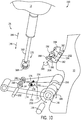
FIG. 2 is a perspective view of acylinder lock system 28 that may be employed with theagricultural harvester 10 ofFIG. 1 . Thecylinder lock system 28 includes a cap-end fixture 50 and a rod-end fixture 52. In some embodiments, the cap-end fixture 50 may couple to acylinder 54 of thepiston cylinder 26. The cap-end fixture 50 includes aframe 56 with one ormore apertures 58 that enable arod 60 of thepiston cylinder 26 to extend through the cap-end fixture 50. Theframe 56 supports afirst contact face 62 that defines a plurality ofprotrusions 64 and recesses 66. Theprotrusions 64 and recesses 66 may form a set of teeth that engage correspondingprotrusions 68 and recesses 70 on asecond contact face 72 of alock piston 74. Theframe 56 may also include opposingside walls respective protrusions protrusions respective recesses protrusions lock piston 74 to block movement of therod 60. In some embodiments, thelock piston 74 may include recesses that receive protrusions on theframe 56 of the cap-end fixture 50. - The rod-
end fixture 52 similarly includes aframe 90. Theframe 90 defines anaperture 91 that enables thelock piston 74 to slide in and out of theframe 90 inaxial directions cylinder lock system 28. In addition to supporting thelock piston 74, theframe 90 defines a plurality ofprotrusions 96 and recesses 98. These extend about an inner circumference of theframe 90 that defines the aperture 91 (e.g., extend circumferentially) and are configured to engage correspondingprotrusions 100 and recesses 102 on an exterior surface 104 (e.g., outer circumferential surface) of thelock piston 74. Theframe 90 of the rod-end fixture 52 also supports one ormore springs 106 within theaperture 91. As will be explained below, thespring 106 facilitates operation of thecylinder lock system 28 by providing a biasing force on thelock piston 74 inaxial direction 92. As illustrated, therod 60, of thepiston cylinder 28, extends through anaperture 108 in thelock piston 74. After passing through thelock piston 74, therod 60 extends through thespring 106 and theframe 90. Therod 60 couples to theframe 90 with apin 110 that passes through an aperture 111 in therod 60. In this way, thepin 110 blocks separation of therod 60 from the rod-end fixture 52. In some embodiments, the cap-end fixture 50 and the rod-end fixture 52 may couple to alinkage 112 that couples to theharvester 10. -
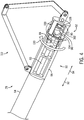
FIG. 3 is a perspective view of acylinder lock system 28 in a first position with therod 60 retracted into thecylinder 54. As therod 60 retracts indirection 92, therod 60 pulls the rod-end fixture 52 and thelock piston 74 towards the cap-end fixture 50. As therod 60 continues to retract indirection 92, thefirst contact face 62 on the cap-end fixture 50 engages/contacts thesecond contact face 72 on thelock piston 74. As illustrated, theprotrusions 64 on thefirst contact face 62 are circumferentially offset from theprotrusions 68 on thesecond contact face 72. This enables theprotrusions 64 on thefirst contact face 62 to enter therecesses 70 on thesecond contact face 72, and theprotrusions 80 on thesecond contact face 72 to enter therecesses 66 on thefirst contact face 62. -
FIG. 4 is a perspective view of acylinder lock system 28 with therod 60 retracted to a second position. As illustrated, in the second position thelock piston 74 continues to move inaxial direction 92 until theprotrusions 64 on thefirst contact face 62 rest withinrecesses 70 on thesecond contact face 72, and theprotrusions 68 on thesecond contact face 72 rest in therecesses 66 on thefirst contact face 62. The axial sliding motion of theprotrusions lock piston 74 incircumferential direction 130 about therod 60. The rotation of thelock piston 74 simultaneously rotates thelugs 88. - As the
rod 60 moves inaxial direction 92, therod 60 pulls theframe 90 of the rod-end fixture 52 compressing thespring 106 between thelock piston 74 and theframe 90 of the rod-end fixture 52. Compression of thespring 106 enables axial separation of theprotrusions 100 and recesses 102 on thelock piston 74 from theprotrusions 96 and recesses 98 onframe 90. Furthermore, as thelock piston 74 rotates, in response to contact between theprotrusions 64 and theprotrusions 68, theprotrusions 100 and recesses 102 on theexterior surface 104 of thelock piston 74 rotate with respect to theprotrusions 96 and recesses 98 on the frame 90 (seeFIG. 5 ). -
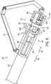
FIG. 6 is a perspective view of acylinder lock system 28 with thelock piston 74 in a third position. In the third position, therod 60 extends indirection 94, or in other words transitions from the position inFIG. 4 (e.g., a fully retracted position). For example, a leak down of the hydraulic pressure may occur enabling to the rod to move inaxial direction 94. In some embodiments, the operator may release/drive the rod 60 (e.g., release by command) enabling therod 60 to move inaxial direction 94. The movement of therod 60 enables thespring 106 to drive thelock piston 74 inaxial direction 92. As thelock piston 74 moves indirection 92, theprotrusions 100 on theexterior surface 104 contact theprotrusions 96 on theframe 90. The contact between theprotrusions 100 on thelock piston 74 and theprotrusions 96 on the rod-end fixture 52 drive rotation of thelock piston 74 incircumferential direction 130. As thelock piston 74 rotates, thelugs 88 align withrecesses protrusions end fixture 50. In this position, thecylinder lock system 28 is in a locked position. In other words, thelugs 88 block axial movement oflock piston 74 and thus the rod-end fixture 52 and therod 60 indirection 94. -
FIG. 7 is a perspective view of thecylinder lock system 28 with therod 60 retracted to the second position. In order to unlock thecylinder lock system 28, therod 60 is again retracted inaxial direction 92 until theprotrusions 64 on thefirst contact face 62 rest withinrecesses 70 on thesecond contact face 72, and theprotrusions 68 on thesecond contact face 72 rest in therecesses 66 on thefirst contact face 62. This axial movement of thelock piston 74 drives rotation of thelock piston 74 incircumferential direction 130 as theprotrusions 64 contact theprotrusions 68. As thelock piston 74 moves axially indirection 92 and rotates incircumferential direction 130, thelugs 88 exit therecesses protrusions frame 56. In other words, thecylinder lock system 28 transitions from a locked state/position to an unlocked state/position. - As the
rod 60 moves inaxial direction 92, therod 60 also pulls theframe 90 of the rod-end fixture 52, which compresses thespring 106 between thelock piston 74 and theframe 90 of the rod-end fixture 52. Compression of thespring 106 enables axial separation of theprotrusions 100 and recesses 102 on thelock piston 74 from theprotrusions 96 and recesses 98 onframe 90. Furthermore, the rotation of thelock piston 74 generated by the contact between theprotrusions 64 on thefirst contact face 62 and theprotrusions 68 on thesecond contact face 72 enables rotation of theprotrusions 100 and recesses 102 on theexterior surface 104 of thelock piston 74 with respect to theprotrusions 96 and recesses 98 on theframe 90 of the rod-end fixture 52 (seeFIG. 5 ). -
FIG. 8 is a perspective view of thecylinder lock system 28 with therod 60 in the third position. After thelugs 88 are out of alignment with theprotrusions rod 60 may extend inaxial direction 94. In other words, the force used to retract therod 60 may be released. The release of therod 60 enables thespring 106 to drive thelock piston 74 inaxial direction 92. As thelock piston 74 moves indirection 92, theprotrusions 100 on theexterior surface 104 contact theprotrusions 96 on theframe 90. The contact between theprotrusions 100 on thelock piston 74 and theprotrusions 96 on the rod-end fixture 52 drive rotation of thelock piston 74 incircumferential direction 130. As thelock piston 74 rotates, thelugs 88 are misaligned with therecesses respective protrusions end fixture 50. In this position, thecylinder lock system 28 is in an unlocked position and prepared for the transition to a locked position when therod 60 is again retracted indirection 92. -
FIG. 9 is a perspective view of thecylinder lock system 28 with therod 60 extended. After unlocking thelock piston 74 from the cap-end fixture 50 therod 60 may again be extended indirection 94 to lower theheader 12 and transition theharvester 10 from a travel mode of operation to a harvesting mode of operation. -
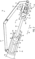
FIG. 10 is a perspective view of acylinder lock system 150 that enables locking of thepiston cylinder 26 by actuation of thepiston cylinder 26. As explained above, theharvester 10 may transition between harvesting and transportation modes of operation. In the harvesting modes of operation, theheader 12 is in a lowered position to enable theharvester 10 to harvest crops. In the transportation mode of operation, theheader 12 is raised to block and/or reduce contact between theheader 12 and the ground. Thecylinder lock system 150 includes a bar 152 (e.g., an A-bar) that rotatingly couples to theharvester 10 withpin 154. For example, thepin 154 may extend through one ormore apertures 156 in thebar 152 and one ormore apertures 158 in theharvester 10. The connection formed by thepin 154 creates a pivot point about which thebar 152 may rotate in response to retraction and extension of therod 160 of thepiston cylinder 26. Therod 160 likewise rotatingly couples to thebar 152 with apin 162. Thepin 162 passes through one ormore apertures 164 in thebar 152. For example, one ormore protrusions 166 may define theapertures 164. In order to couple therod 160 to thebar 152, thepin 162 extends through theapertures 164 in thebar 152 and through anaperture 168 in anend 170 of thebar 152. - The
bar 152 supports a dog or latch 172 that enables the locking of theheader 12 in a raised position by actuating therod 160. The dog or latch 172 couples to thebar 152 with apin 174. Thepin 174 extends through anaperture 176 in the dog orlatch 172, which enables the dog or latch 172 to rotate about thepin 174. InFIG. 10 thedog 172 is biased to a first position with aspring 178 that couples to thepin 174 and to thedog 172. Thedog 172 remains in this position until it contacts thelatch pin 180. Thelatch pin 180 couples to and is supported by brackets 182 (e.g., L-shaped brackets) that couple to theharvester 10. - In operation, the
header 12 is raised by retracting therod 160. As therod 160 retracts indirection 184, thebar 152 rotates indirection 186 about thepin 154 that couples thebar 152 to theharvester 10. As thebar 152 rotates, thedog 172 remains in the first position until it contacts thelatch pin 180 illustrated by the dasheddog 188. As therod 160 continues to retract and thebar 152 continues to rotate, thedog 188 contacts thelatch pin 180. The contact force between thedog 188 and thelatch pin 180 overcomes the spring force of thespring 178 enabling thedog 188 to rotate indirection 190 about thepin 174. As thedog 188 rotates about thelatch pin 180, thedog 188 transition to a second or locked position illustrated by the dasheddog 192. In this position, a stop lobe orledge 194 rests on thelatch pin 180 blocking movement of therod 160 indirection 196. In other words, thedog 188 locks theheader 12 in a raised position. In order to again lower theheader 12, therod 160 is driven or retracted indirection 184. The retraction again causes thebar 152 to rotate indirection 186, which further drives rotation of thedog 172 about thelatch pin 180. The continued rotation and raising of thedog 172 enables thedog 172 to slide over and clear thelatch pin 180. Once thedog 172 clears thelatch pin 180, thespring 178 returns thedog 172 to its original position (e.g., the first position) illustrated with dashedline 198. In this position, therod 160 may again extend indirection 196 to lower theheader 12, because as thebar 152 rotates indirection 200 thelatch pin 180 contacts a rear surface 202 of thedog 172. Contact between the rear surface 202 of thedog 172 and thelatch pin 180 rotates thedog 172 indirection 204 as thedog 172 slides over thelatch pin 180. Again once thedog 172 clears thelatch pin 180, thespring 178 biases thedog 172 to the original position or first position as thebar 152 rotates indirection 200 and is lowered away from thelatch pin 180 indirection 196. - While only certain features have been illustrated and described herein, many modifications and changes will occur to those skilled in the art. It is, therefore, to be understood that the appended claims are intended to cover all such modifications and changes as fall within the true spirit of the disclosure.
Claims (8)
- An agricultural system, comprising:a cylinder;a rod configured to move axially in and out of the cylinder;a cylinder lock system configured to control movement of the rod and/or cylinder, the cylinder lock system comprising:a cap-end fixture configured to couple to the cylinder and configured to receive the rod;a rod-end fixture configured to couple to an end of the rod; anda lock piston, the lock piston comprising a protrusion, wherein the lock piston is configured to rotate about the rod and selectively couple the protrusion to the cap-end fixture to lock and unlock the rod-end fixture to the cap-end fixture.
- The agricultural system of claim 1, wherein the cap-end fixture comprises a recess configured to receive the protrusion on the lock piston.
- The agricultural system of claim 1, wherein the cap-end fixture comprises a first contoured contact face configured to engage a second contoured face on the locking cylinder to rotate the locking cylinder.
- The agricultural system of claim 1, wherein the rod-end fixture comprises a frame that defines an aperture that receives the locking cylinder, wherein the locking cylinder is configured to move axially in and out of the aperture.
- The agricultural system of claim 4, comprising a spring within the aperture of the rod-end fixture.
- The agricultural system of claim 1, wherein the rod-end fixture comprises a first contoured contact surface configured to engage a second contoured surface on the locking cylinder to rotate the locking cylinder.
- The agricultural system of claim 1, comprising a linkage coupled to the cap-end fixture and to the rod-end fixture.
- The agricultural system of claim 1, wherein the cylinder is a hydraulic cylinder.
Applications Claiming Priority (1)
| Application Number | Priority Date | Filing Date | Title |
|---|---|---|---|
| US201962790160P | 2019-01-09 | 2019-01-09 |
Publications (2)
| Publication Number | Publication Date |
|---|---|
| EP3679783A1 true EP3679783A1 (en) | 2020-07-15 |
| EP3679783B1 EP3679783B1 (en) | 2022-03-09 |
Family
ID=69157641
Family Applications (1)
| Application Number | Title | Priority Date | Filing Date |
|---|---|---|---|
| EP20151041.9A Active EP3679783B1 (en) | 2019-01-09 | 2020-01-09 | Cylinder lock system |
Country Status (2)
| Country | Link |
|---|---|
| US (1) | US11849673B2 (en) |
| EP (1) | EP3679783B1 (en) |
Families Citing this family (3)
| Publication number | Priority date | Publication date | Assignee | Title |
|---|---|---|---|---|
| WO2020101841A1 (en) * | 2018-11-16 | 2020-05-22 | Cnh Industrial America Llc | Locking mechanism for an agricultural header |
| US12279557B2 (en) | 2021-11-05 | 2025-04-22 | Cnh Industrial America Llc | Piston lock system for agricultural equipment |
| US11473600B1 (en) * | 2021-11-05 | 2022-10-18 | Cnh Industrial America Llc | Piston lock system for agricultural equipment |
Citations (2)
| Publication number | Priority date | Publication date | Assignee | Title |
|---|---|---|---|---|
| US3799036A (en) * | 1972-07-17 | 1974-03-26 | R Slaughter | Self-locking fluid operated cylinder |
| DE102016119251A1 (en) * | 2016-10-10 | 2018-04-12 | Fbr Facondrehteile Gmbh | Hydromechanical locking cylinder and hydraulic control system for its operation |
Family Cites Families (11)
| Publication number | Priority date | Publication date | Assignee | Title |
|---|---|---|---|---|
| GB608704A (en) | 1946-02-27 | 1948-09-20 | Messier Aircraft Equipment Ltd | Improvements in or relating to fluid-pressure operated jacks |
| US2580100A (en) | 1946-08-12 | 1951-12-25 | Wayne A Yocom | Implement raising and locking device |
| US2994544A (en) | 1959-12-21 | 1961-08-01 | Int Harvester Co | Hydraulic ram mounting |
| US4340158A (en) * | 1980-06-13 | 1982-07-20 | Realex Corporation | Vent-sealing, down-locked pump dispenser |
| US4529215A (en) | 1983-02-03 | 1985-07-16 | Tci, Inc. | Hydraulic cylinder safety lock |
| DE10353903A1 (en) | 2003-11-18 | 2005-06-16 | Suspa Holding Gmbh | Length adjustable compression spring |
| US9554500B2 (en) | 2008-08-27 | 2017-01-31 | Unverferth Manufacturing Company, Inc. | Gravitational latch for wing lift wheels |
| DE102011015959A1 (en) | 2011-04-04 | 2012-10-04 | Stabilus Gmbh | Blockable piston-cylinder unit |
| US8931246B2 (en) | 2012-12-06 | 2015-01-13 | Cnh Industrial America Llc | Automatically engaging and disengaging header lock assembly |
| US9131638B2 (en) | 2013-04-29 | 2015-09-15 | Cnh Industrial America Llc | Intermediate lift cylinder lock for extra tall stubble biomass operation |
| WO2015153692A1 (en) * | 2014-03-31 | 2015-10-08 | LAD Ag Industries, Inc. | Safety block |
-
2020
- 2020-01-09 EP EP20151041.9A patent/EP3679783B1/en active Active
- 2020-01-09 US US16/738,715 patent/US11849673B2/en active Active
Patent Citations (2)
| Publication number | Priority date | Publication date | Assignee | Title |
|---|---|---|---|---|
| US3799036A (en) * | 1972-07-17 | 1974-03-26 | R Slaughter | Self-locking fluid operated cylinder |
| DE102016119251A1 (en) * | 2016-10-10 | 2018-04-12 | Fbr Facondrehteile Gmbh | Hydromechanical locking cylinder and hydraulic control system for its operation |
Also Published As
| Publication number | Publication date |
|---|---|
| BR102020000380A2 (en) | 2020-09-24 |
| US11849673B2 (en) | 2023-12-26 |
| EP3679783B1 (en) | 2022-03-09 |
| US20200217104A1 (en) | 2020-07-09 |
Similar Documents
| Publication | Publication Date | Title |
|---|---|---|
| US11849673B2 (en) | Cylinder lock system | |
| EP2740346B1 (en) | Automatically engaging and disengaging header lock assembly | |
| EP2531016B1 (en) | Agricultural harvester with automatic header coupling | |
| US12082529B2 (en) | Wheel locking assembly for a harvester header | |
| EP2745673B1 (en) | Combine side-shake control system slider joint | |
| US20210185875A1 (en) | Locking mechanism for an agricultural header | |
| EP3879954A1 (en) | Locking mechanism for an agricultural header | |
| EP2989881B1 (en) | Header latch mechanism for agricultural vehicle | |
| IL164542A (en) | Baler gate linkage and latch structure | |
| EP3772270B1 (en) | Automatic header latch | |
| US7497775B1 (en) | Rear accessible sieve retainer | |
| EP3855886A1 (en) | Crop cutting device, agricultural machine comprising such crop cutting device and knife removal method from crop cutting device | |
| US12245552B2 (en) | Adjustable reel arm | |
| US20190183050A1 (en) | Harvester with header lift assembly | |
| CN105340464A (en) | Combine harvester | |
| US11547058B2 (en) | Agricultural baler | |
| EP3618603B1 (en) | Over-center locking system for a chaff pan of an agricultural harvester | |
| US20240423123A1 (en) | Locking assembly for an arm of an agricultural header | |
| US7472481B2 (en) | Method of manufacturing a cotton picker basket | |
| CA3124326A1 (en) | Folding harvester with crop divider lift and frame lock | |
| JP4578277B2 (en) | Root crop harvesting machine | |
| JP2004089060A (en) | Combine harvester | |
| US7426818B2 (en) | Method of operating cotton accumulator and compactor | |
| KR102524801B1 (en) | Combine | |
| WO2024227476A1 (en) | Folding pick-up attachment for a harvesting machine |
Legal Events
| Date | Code | Title | Description |
|---|---|---|---|
| PUAI | Public reference made under article 153(3) epc to a published international application that has entered the european phase |
Free format text: ORIGINAL CODE: 0009012 |
|
| STAA | Information on the status of an ep patent application or granted ep patent |
Free format text: STATUS: THE APPLICATION HAS BEEN PUBLISHED |
|
| AK | Designated contracting states |
Kind code of ref document: A1 Designated state(s): AL AT BE BG CH CY CZ DE DK EE ES FI FR GB GR HR HU IE IS IT LI LT LU LV MC MK MT NL NO PL PT RO RS SE SI SK SM TR |
|
| AX | Request for extension of the european patent |
Extension state: BA ME |
|
| STAA | Information on the status of an ep patent application or granted ep patent |
Free format text: STATUS: REQUEST FOR EXAMINATION WAS MADE |
|
| 17P | Request for examination filed |
Effective date: 20210115 |
|
| RBV | Designated contracting states (corrected) |
Designated state(s): AL AT BE BG CH CY CZ DE DK EE ES FI FR GB GR HR HU IE IS IT LI LT LU LV MC MK MT NL NO PL PT RO RS SE SI SK SM TR |
|
| GRAP | Despatch of communication of intention to grant a patent |
Free format text: ORIGINAL CODE: EPIDOSNIGR1 |
|
| STAA | Information on the status of an ep patent application or granted ep patent |
Free format text: STATUS: GRANT OF PATENT IS INTENDED |
|
| RIC1 | Information provided on ipc code assigned before grant |
Ipc: A01D 41/14 20060101AFI20210427BHEP Ipc: A01D 75/20 20060101ALI20210427BHEP Ipc: F15B 15/26 20060101ALI20210427BHEP |
|
| INTG | Intention to grant announced |
Effective date: 20210526 |
|
| GRAJ | Information related to disapproval of communication of intention to grant by the applicant or resumption of examination proceedings by the epo deleted |
Free format text: ORIGINAL CODE: EPIDOSDIGR1 |
|
| STAA | Information on the status of an ep patent application or granted ep patent |
Free format text: STATUS: REQUEST FOR EXAMINATION WAS MADE |
|
| GRAP | Despatch of communication of intention to grant a patent |
Free format text: ORIGINAL CODE: EPIDOSNIGR1 |
|
| STAA | Information on the status of an ep patent application or granted ep patent |
Free format text: STATUS: GRANT OF PATENT IS INTENDED |
|
| INTC | Intention to grant announced (deleted) | ||
| INTG | Intention to grant announced |
Effective date: 20211020 |
|
| GRAS | Grant fee paid |
Free format text: ORIGINAL CODE: EPIDOSNIGR3 |
|
| GRAA | (expected) grant |
Free format text: ORIGINAL CODE: 0009210 |
|
| STAA | Information on the status of an ep patent application or granted ep patent |
Free format text: STATUS: THE PATENT HAS BEEN GRANTED |
|
| AK | Designated contracting states |
Kind code of ref document: B1 Designated state(s): AL AT BE BG CH CY CZ DE DK EE ES FI FR GB GR HR HU IE IS IT LI LT LU LV MC MK MT NL NO PL PT RO RS SE SI SK SM TR |
|
| REG | Reference to a national code |
Ref country code: CH Ref legal event code: EP Ref country code: AT Ref legal event code: REF Ref document number: 1473378 Country of ref document: AT Kind code of ref document: T Effective date: 20220315 |
|
| REG | Reference to a national code |
Ref country code: IE Ref legal event code: FG4D |
|
| REG | Reference to a national code |
Ref country code: DE Ref legal event code: R096 Ref document number: 602020002071 Country of ref document: DE |
|
| REG | Reference to a national code |
Ref country code: LT Ref legal event code: MG9D |
|
| REG | Reference to a national code |
Ref country code: NL Ref legal event code: MP Effective date: 20220309 |
|
| PG25 | Lapsed in a contracting state [announced via postgrant information from national office to epo] |
Ref country code: SE Free format text: LAPSE BECAUSE OF FAILURE TO SUBMIT A TRANSLATION OF THE DESCRIPTION OR TO PAY THE FEE WITHIN THE PRESCRIBED TIME-LIMIT Effective date: 20220309 Ref country code: RS Free format text: LAPSE BECAUSE OF FAILURE TO SUBMIT A TRANSLATION OF THE DESCRIPTION OR TO PAY THE FEE WITHIN THE PRESCRIBED TIME-LIMIT Effective date: 20220309 Ref country code: NO Free format text: LAPSE BECAUSE OF FAILURE TO SUBMIT A TRANSLATION OF THE DESCRIPTION OR TO PAY THE FEE WITHIN THE PRESCRIBED TIME-LIMIT Effective date: 20220609 Ref country code: LT Free format text: LAPSE BECAUSE OF FAILURE TO SUBMIT A TRANSLATION OF THE DESCRIPTION OR TO PAY THE FEE WITHIN THE PRESCRIBED TIME-LIMIT Effective date: 20220309 Ref country code: HR Free format text: LAPSE BECAUSE OF FAILURE TO SUBMIT A TRANSLATION OF THE DESCRIPTION OR TO PAY THE FEE WITHIN THE PRESCRIBED TIME-LIMIT Effective date: 20220309 Ref country code: BG Free format text: LAPSE BECAUSE OF FAILURE TO SUBMIT A TRANSLATION OF THE DESCRIPTION OR TO PAY THE FEE WITHIN THE PRESCRIBED TIME-LIMIT Effective date: 20220609 |
|
| REG | Reference to a national code |
Ref country code: AT Ref legal event code: MK05 Ref document number: 1473378 Country of ref document: AT Kind code of ref document: T Effective date: 20220309 |
|
| PG25 | Lapsed in a contracting state [announced via postgrant information from national office to epo] |
Ref country code: LV Free format text: LAPSE BECAUSE OF FAILURE TO SUBMIT A TRANSLATION OF THE DESCRIPTION OR TO PAY THE FEE WITHIN THE PRESCRIBED TIME-LIMIT Effective date: 20220309 Ref country code: GR Free format text: LAPSE BECAUSE OF FAILURE TO SUBMIT A TRANSLATION OF THE DESCRIPTION OR TO PAY THE FEE WITHIN THE PRESCRIBED TIME-LIMIT Effective date: 20220610 Ref country code: FI Free format text: LAPSE BECAUSE OF FAILURE TO SUBMIT A TRANSLATION OF THE DESCRIPTION OR TO PAY THE FEE WITHIN THE PRESCRIBED TIME-LIMIT Effective date: 20220309 |
|
| PG25 | Lapsed in a contracting state [announced via postgrant information from national office to epo] |
Ref country code: NL Free format text: LAPSE BECAUSE OF FAILURE TO SUBMIT A TRANSLATION OF THE DESCRIPTION OR TO PAY THE FEE WITHIN THE PRESCRIBED TIME-LIMIT Effective date: 20220309 |
|
| PG25 | Lapsed in a contracting state [announced via postgrant information from national office to epo] |
Ref country code: SM Free format text: LAPSE BECAUSE OF FAILURE TO SUBMIT A TRANSLATION OF THE DESCRIPTION OR TO PAY THE FEE WITHIN THE PRESCRIBED TIME-LIMIT Effective date: 20220309 Ref country code: SK Free format text: LAPSE BECAUSE OF FAILURE TO SUBMIT A TRANSLATION OF THE DESCRIPTION OR TO PAY THE FEE WITHIN THE PRESCRIBED TIME-LIMIT Effective date: 20220309 Ref country code: RO Free format text: LAPSE BECAUSE OF FAILURE TO SUBMIT A TRANSLATION OF THE DESCRIPTION OR TO PAY THE FEE WITHIN THE PRESCRIBED TIME-LIMIT Effective date: 20220309 Ref country code: PT Free format text: LAPSE BECAUSE OF FAILURE TO SUBMIT A TRANSLATION OF THE DESCRIPTION OR TO PAY THE FEE WITHIN THE PRESCRIBED TIME-LIMIT Effective date: 20220711 Ref country code: ES Free format text: LAPSE BECAUSE OF FAILURE TO SUBMIT A TRANSLATION OF THE DESCRIPTION OR TO PAY THE FEE WITHIN THE PRESCRIBED TIME-LIMIT Effective date: 20220309 Ref country code: EE Free format text: LAPSE BECAUSE OF FAILURE TO SUBMIT A TRANSLATION OF THE DESCRIPTION OR TO PAY THE FEE WITHIN THE PRESCRIBED TIME-LIMIT Effective date: 20220309 Ref country code: CZ Free format text: LAPSE BECAUSE OF FAILURE TO SUBMIT A TRANSLATION OF THE DESCRIPTION OR TO PAY THE FEE WITHIN THE PRESCRIBED TIME-LIMIT Effective date: 20220309 Ref country code: AT Free format text: LAPSE BECAUSE OF FAILURE TO SUBMIT A TRANSLATION OF THE DESCRIPTION OR TO PAY THE FEE WITHIN THE PRESCRIBED TIME-LIMIT Effective date: 20220309 |
|
| PG25 | Lapsed in a contracting state [announced via postgrant information from national office to epo] |
Ref country code: PL Free format text: LAPSE BECAUSE OF FAILURE TO SUBMIT A TRANSLATION OF THE DESCRIPTION OR TO PAY THE FEE WITHIN THE PRESCRIBED TIME-LIMIT Effective date: 20220309 Ref country code: IS Free format text: LAPSE BECAUSE OF FAILURE TO SUBMIT A TRANSLATION OF THE DESCRIPTION OR TO PAY THE FEE WITHIN THE PRESCRIBED TIME-LIMIT Effective date: 20220709 Ref country code: AL Free format text: LAPSE BECAUSE OF FAILURE TO SUBMIT A TRANSLATION OF THE DESCRIPTION OR TO PAY THE FEE WITHIN THE PRESCRIBED TIME-LIMIT Effective date: 20220309 |
|
| REG | Reference to a national code |
Ref country code: DE Ref legal event code: R097 Ref document number: 602020002071 Country of ref document: DE |
|
| PLBE | No opposition filed within time limit |
Free format text: ORIGINAL CODE: 0009261 |
|
| STAA | Information on the status of an ep patent application or granted ep patent |
Free format text: STATUS: NO OPPOSITION FILED WITHIN TIME LIMIT |
|
| PG25 | Lapsed in a contracting state [announced via postgrant information from national office to epo] |
Ref country code: DK Free format text: LAPSE BECAUSE OF FAILURE TO SUBMIT A TRANSLATION OF THE DESCRIPTION OR TO PAY THE FEE WITHIN THE PRESCRIBED TIME-LIMIT Effective date: 20220309 |
|
| 26N | No opposition filed |
Effective date: 20221212 |
|
| PG25 | Lapsed in a contracting state [announced via postgrant information from national office to epo] |
Ref country code: SI Free format text: LAPSE BECAUSE OF FAILURE TO SUBMIT A TRANSLATION OF THE DESCRIPTION OR TO PAY THE FEE WITHIN THE PRESCRIBED TIME-LIMIT Effective date: 20220309 |
|
| REG | Reference to a national code |
Ref country code: CH Ref legal event code: PL |
|
| PG25 | Lapsed in a contracting state [announced via postgrant information from national office to epo] |
Ref country code: LU Free format text: LAPSE BECAUSE OF NON-PAYMENT OF DUE FEES Effective date: 20230109 |
|
| REG | Reference to a national code |
Ref country code: BE Ref legal event code: MM Effective date: 20230131 |
|
| PG25 | Lapsed in a contracting state [announced via postgrant information from national office to epo] |
Ref country code: LI Free format text: LAPSE BECAUSE OF NON-PAYMENT OF DUE FEES Effective date: 20230131 Ref country code: CH Free format text: LAPSE BECAUSE OF NON-PAYMENT OF DUE FEES Effective date: 20230131 |
|
| PG25 | Lapsed in a contracting state [announced via postgrant information from national office to epo] |
Ref country code: BE Free format text: LAPSE BECAUSE OF NON-PAYMENT OF DUE FEES Effective date: 20230131 |
|
| PG25 | Lapsed in a contracting state [announced via postgrant information from national office to epo] |
Ref country code: IE Free format text: LAPSE BECAUSE OF NON-PAYMENT OF DUE FEES Effective date: 20230109 |
|
| PG25 | Lapsed in a contracting state [announced via postgrant information from national office to epo] |
Ref country code: MC Free format text: LAPSE BECAUSE OF FAILURE TO SUBMIT A TRANSLATION OF THE DESCRIPTION OR TO PAY THE FEE WITHIN THE PRESCRIBED TIME-LIMIT Effective date: 20220309 |
|
| PG25 | Lapsed in a contracting state [announced via postgrant information from national office to epo] |
Ref country code: MC Free format text: LAPSE BECAUSE OF FAILURE TO SUBMIT A TRANSLATION OF THE DESCRIPTION OR TO PAY THE FEE WITHIN THE PRESCRIBED TIME-LIMIT Effective date: 20220309 |
|
| PG25 | Lapsed in a contracting state [announced via postgrant information from national office to epo] |
Ref country code: CY Free format text: LAPSE BECAUSE OF FAILURE TO SUBMIT A TRANSLATION OF THE DESCRIPTION OR TO PAY THE FEE WITHIN THE PRESCRIBED TIME-LIMIT; INVALID AB INITIO Effective date: 20200109 |
|
| PG25 | Lapsed in a contracting state [announced via postgrant information from national office to epo] |
Ref country code: HU Free format text: LAPSE BECAUSE OF FAILURE TO SUBMIT A TRANSLATION OF THE DESCRIPTION OR TO PAY THE FEE WITHIN THE PRESCRIBED TIME-LIMIT; INVALID AB INITIO Effective date: 20200109 |
|
| PG25 | Lapsed in a contracting state [announced via postgrant information from national office to epo] |
Ref country code: TR Free format text: LAPSE BECAUSE OF FAILURE TO SUBMIT A TRANSLATION OF THE DESCRIPTION OR TO PAY THE FEE WITHIN THE PRESCRIBED TIME-LIMIT Effective date: 20220309 |
|
| PGFP | Annual fee paid to national office [announced via postgrant information from national office to epo] |
Ref country code: GB Payment date: 20260126 Year of fee payment: 7 |
|
| PGFP | Annual fee paid to national office [announced via postgrant information from national office to epo] |
Ref country code: DE Payment date: 20260127 Year of fee payment: 7 |
|
| PGFP | Annual fee paid to national office [announced via postgrant information from national office to epo] |
Ref country code: IT Payment date: 20260123 Year of fee payment: 7 |
|
| PGFP | Annual fee paid to national office [announced via postgrant information from national office to epo] |
Ref country code: FR Payment date: 20260126 Year of fee payment: 7 |