EP3679780A1 - Grass trimmer and control method therefor - Google Patents
Grass trimmer and control method therefor Download PDFInfo
- Publication number
- EP3679780A1 EP3679780A1 EP18868343.7A EP18868343A EP3679780A1 EP 3679780 A1 EP3679780 A1 EP 3679780A1 EP 18868343 A EP18868343 A EP 18868343A EP 3679780 A1 EP3679780 A1 EP 3679780A1
- Authority
- EP
- European Patent Office
- Prior art keywords
- grass trimmer
- line
- grass
- head
- effective part
- Prior art date
- Legal status (The legal status is an assumption and is not a legal conclusion. Google has not performed a legal analysis and makes no representation as to the accuracy of the status listed.)
- Granted
Links
Images






Classifications
-
- A—HUMAN NECESSITIES
- A01—AGRICULTURE; FORESTRY; ANIMAL HUSBANDRY; HUNTING; TRAPPING; FISHING
- A01D—HARVESTING; MOWING
- A01D34/00—Mowers; Mowing apparatus of harvesters
- A01D34/006—Control or measuring arrangements
-
- A—HUMAN NECESSITIES
- A01—AGRICULTURE; FORESTRY; ANIMAL HUSBANDRY; HUNTING; TRAPPING; FISHING
- A01D—HARVESTING; MOWING
- A01D34/00—Mowers; Mowing apparatus of harvesters
-
- A—HUMAN NECESSITIES
- A01—AGRICULTURE; FORESTRY; ANIMAL HUSBANDRY; HUNTING; TRAPPING; FISHING
- A01D—HARVESTING; MOWING
- A01D34/00—Mowers; Mowing apparatus of harvesters
- A01D34/006—Control or measuring arrangements
- A01D34/008—Control or measuring arrangements for automated or remotely controlled operation
-
- A—HUMAN NECESSITIES
- A01—AGRICULTURE; FORESTRY; ANIMAL HUSBANDRY; HUNTING; TRAPPING; FISHING
- A01D—HARVESTING; MOWING
- A01D34/00—Mowers; Mowing apparatus of harvesters
- A01D34/01—Mowers; Mowing apparatus of harvesters characterised by features relating to the type of cutting apparatus
- A01D34/412—Mowers; Mowing apparatus of harvesters characterised by features relating to the type of cutting apparatus having rotating cutters
- A01D34/416—Flexible line cutters
-
- A—HUMAN NECESSITIES
- A01—AGRICULTURE; FORESTRY; ANIMAL HUSBANDRY; HUNTING; TRAPPING; FISHING
- A01D—HARVESTING; MOWING
- A01D34/00—Mowers; Mowing apparatus of harvesters
- A01D34/01—Mowers; Mowing apparatus of harvesters characterised by features relating to the type of cutting apparatus
- A01D34/412—Mowers; Mowing apparatus of harvesters characterised by features relating to the type of cutting apparatus having rotating cutters
- A01D34/416—Flexible line cutters
- A01D34/4161—Means for feeding cutter line
- A01D34/4162—Means for feeding cutter line automatically
-
- A—HUMAN NECESSITIES
- A01—AGRICULTURE; FORESTRY; ANIMAL HUSBANDRY; HUNTING; TRAPPING; FISHING
- A01D—HARVESTING; MOWING
- A01D75/00—Accessories for harvesters or mowers
- A01D75/28—Control mechanisms for harvesters or mowers when moving on slopes; Devices preventing lateral pull
- A01D75/285—Control mechanisms for harvesters or mowers when moving on slopes; Devices preventing lateral pull with arrangements for holding the harvesting or mowing apparatus in a horizontal position
Definitions
- the present disclosure relates to a grass trimmer and a control method for a grass trimmer, and in particular to a grass trimmer line releasing method for the grass trimmer.
- a grass trimmer As a garden tool, a grass trimmer is widely favored by a user. It is known that after the grass trimmer works for a period of time, the length of a grass trimmer line may be reduced due to wear and tear, which will reduce the range of trimming grass and greatly affect the efficiency of trimming grass. At this time, the user wants the length of the grass trimmer line to be increased. For this reason, the grass trimmer needs to perform the operation of grass trimmer line releasing.
- the existing grass trimmer on the one hand, it is difficult for the user to find out whether a length of the grass trimmer line satisfies the needs; on the other hand, the existing grass trimmer requires manual operation by the user to complete the grass trimmer line releasing function.
- an object of the present disclosure is to provide a grass trimmer capable of releasing a grass trimmer line intelligently.
- a grass trimmer includes an operating device configured for a user to operate and a grass trimmer device including a grass trimmer head and a motor configured to drive the grass trimmer head.
- the grass trimmer head includes: a spool configured for a grass trimmer line winding around and capable of rotating around a first axis and a housing formed with an accommodating cavity configured to accommodate at least a part of the spool and formed with an aperture configured for the grass trimmer line to pass through.
- a part of the grass trimmer line protruding outside the housing is defined as an effective part of the grass trimmer line.
- the grass trimmer further includes a controller configured to control the grass trimmer head to release a grass trimmer line when the grass trimmer head is mounted with the grass trimmer line and a length of the effective part is detected to be less than or equal to a preset value.
- the grass trimmer further includes: a line feeding device configured to have a first working mode for preventing the grass trimmer head from releasing the grass trimmer line and a second working mode for allowing the grass trimmer head to release the grass trimmer line; when the line feeding device is in the first working mode, the housing is stationary relative to the spool, and the grass trimmer head is capable of trimming grass; when the line feeding device is in the second working mode, the spool rotates relative to the housing, and the grass trimmer head releases the grass trimmer line.
- controller is connected to the motor, and the controller is at least capable of switching the grass trimmer head from the first working mode to the second working mode by controlling the motor to be accelerated by a first rotation speed at which the grass trimmer is in a normal trimming state.
- the grass trimmer further includes: a detection device configured to detect a characterization parameter that reflects a change in the length of the effective part when the grass trimmer line is mounted to the grass trimmer; the controller is connected to the detection device, and when the characterization parameter reflects that the length of the effective part is less than or equal to the preset value, the controller controls the grass trimmer head to release the grass trimmer line.
- a correspondence relationship between the characterization parameter and the length of the effective part is stored in the controller.
- the characterization parameter is a current flowing through the motor, or a torque of the grass trimmer line, or a noise outside the housing of the grass trimmer head.
- the grass trimmer further includes: a line feeding device cojnfigured to have a first working mode for preventing the grass trimmer head from releasing the grass trimmer line and a second working mode for allowing the grass trimmer head to release the grass trimmer line.
- the line feeding device includes: a movable block capable of rotating with rotation of the spool and sliding along a direction of a first straight line relative to the spool.
- the movable block is formed with an engagement portion; the housing is formed with a reception portion capable of cooperating with the engagement portion to cause the housing and the spool relatively stationary; in response to determining that the line feeding device is in the first working mode, the movable block slides to a position where the engagement portion and the reception portion cooperate with each other; in response to determining that the line feeding device is in the second working mode, the movable block slides to a position where the engagement portion and the reception portion are separated from each other.
- reception portion is formed on an outer side of the housing facing toward the motor; the movable block is at least partially disposed outside the accommodating cavity.
- the line feeding device includes: a biasing member configured to bias the movable block to move toward the position where the engagement portion and the reception portion cooperate with each other.
- a center of gravity of the movable block and the biasing member are respectively disposed on two sides of a plane passing through the first axis and perpendicular to the first straight line.
- the grass trimmer further includes: a detection device configured to detect the length of the effective part; where the detection device is connected to the controller, and in response to determining that the length of the effective part detected by the detection device is less than or equal to the preset value, the controller controls the grass trimmer head to release the grass trimmer line.
- the grass trimmer further includes: a detection device configured to detect whether the length of the effective part is less than or equal to the preset value; where the controller is connected to the detection device, and in response to determining that the detection device detects that the length of the effective part is less than or equal to the preset value, the controller controls the grass trimmer head to release the grass trimmer line.
- the grass trimmer includes a grass trimmer device, the grass trimmer device includes a grass trimmer head and a motor configured to drive the grass trimmer head to rotate, and when the grass trimmer head is mounted with a grass trimmer line, the grass trimmer line is driven to rotate to cut grass; when the grass trimmer head is mounted with the grass trimmer line, a part of the grass trimmer line protruding outside the grass trimmer head is defined as an effective part of the grass trimmer line.
- the control method includes steps of: detecting and determining whether a length of the effective part is less than or equal to a preset value; in response to determining that the length of the effective part is less than or equal to the preset value, controlling the grass trimmer head to release a grass trimmer line.
- the motor is controlled to accelerate from a first rotation speed to a second rotation speed to cause the grass trimmer head to release the grass trimmer line.
- control method further includes a step of controlling the motor to decelerate from the second rotation speed to a third rotation speed.
- the third rotation speed is smaller than the first rotation speed.
- a difference between the third rotation speed and the second rotation speed is greater than a difference between the second rotation speed and the first rotation speed.
- the advantage of the present disclosure is that: the grass trimmer is capable of achieving intelligent and automatic grass trimmer line releasing.
- a grass trimmer 100 shown in FIG. 1 includes an operating device 11, a grass trimmer device 12, and a connecting device 13.
- the operating device 11 includes a handle 111, an auxiliary handle 112, and a main switch 113.
- the handle 111 and the auxiliary handle 112 are respectively used by two hands of a user to hold, so that the user can operate the grass trimmer 100 more stably.
- the main switch 113 may be disposed on the handle 111. When the user holds the handle 111, the user can directly operate the main switch 113 to control the grass trimmer 100 to perform trimming.
- the operating device 11 may further include a rear housing 114 for forming a coupling portion 114a, and the coupling portion 114a is used for coupling a power supply device to power the grass trimmer 100.
- the coupling portion 114a is capable of coupling a battery pack to power the grass trimmer 100.
- the handle 111 may be integrally formed with the rear housing 114, or the handle 111 may be formed separately from the rear housing 114.
- the grass trimmer device 12 includes a grass trimmer head 20, a motor 121 and a motor housing 122.
- the grass trimmer head 20 is used for trimming
- the motor 121 includes a motor shaft 121a for driving the grass trimmer head 20 to rotate.
- the motor shaft 121a can rotate about a first axis 101
- the motor housing 122 is used for accommodating the motor 121.
- the connecting device 13 is used for connecting the operating device 11 and the grass trimmer device 12 so that the operating device 11 and the grass trimmer device 12 constitute a whole that can move together and form the grass trimmer 100.
- the connecting device 13 includes a connecting rod 131.
- One end of the connecting rod 131 is connected to the motor housing 122, and the other end of the connecting rod 131 may be connected to the rear housing 114 of the operating device 11.
- the auxiliary handle 112 is also mounted to the connecting rod 131, and the auxiliary handle 112 may also be located between the rear housing 114 and the motor housing 122.
- the grass trimmer device 12 further includes a fan 123 which is at least partially disposed between the motor 121 and the grass trimmer head 20.
- the fan 123 is mounted to the motor shaft 121a and rotates together with the motor shaft 121a to dissipate heat from the motor 121.
- the grass trimmer head 20 further includes a housing 21, a spool 22, a grass trimmer line 23 and a line feeding device 24.
- An accommodating cavity 211 is formed around the housing 21.
- One side of the housing 21 forming the accommodating cavity 211 is an inner side of the housing 21, and the other side of the housing 21 opposite the inner side is an outer side.
- the housing 21 may specifically include an upper housing portion 212 and a lower housing portion 213, and the upper housing portion 212 and the lower housing portion 213 are integrally formed by a snap connection.
- the upper housing portion 212 and the lower housing portion 213 are connected to form the accommodating cavity 211 when connected.
- the spool 22 is at least partially disposed in the accommodating cavity 211, that is, the spool 22 is disposed inside the housing 21.
- the spool 22 is used for winding the grass trimmer line 23 around, and the grass trimmer line 23 is used for trimming.
- the housing 21 is further formed with an aperture 214 for the grass trimmer line 23 to protrude to the outside of the housing 21, and the number of apertures 214 is two.
- the part of the grass trimmer line 23 protruding through the apertures 214 to the outside of the housing 21 is defined as an effective part 231 of the grass trimmer line 23.
- the effective part 231 of the grass trimmer line 23 is capable of cutting weeds when rotating at a high speed.
- the length of the effective part 231 of the grass trimmer line 23 can reach a preset value, that is, the length of the effective part 231 of the grass trimmer line 23 is necessary to be greater than or equal to the preset value.
- the preset value of the grass trimmer line 23 here may be a fixed value, or may of course be a variable value set by a user in advance.
- the line feeding device 24 is used for controlling whether the grass trimmer head 20 is releasing the grass trimmer line.
- the line feeding device 24 has a first working mode that makes the grass trimmer head 20 unable to release the grass trimmer line, and the first working mode may also be considered as a trimming mode.
- the line feeding device 24 also has a second working mode that enables the grass trimmer head 20 to release the grass trimmer line, and the second working mode may also be considered as a grass trimmer line releasing mode.
- the spool 22 and the housing 21 are relatively stationary.
- the spool 22 and the housing 21 will be driven by the motor shaft 121a to rotate synchronously, so that the length of the effective part 231 of the grass trimmer line 23 wound on the spool 22 at this time protruding outside the housing 21 does not change, that is, the grass trimmer line 23 cannot be released, and the grass trimmer head 20 is in a normal working state at this time.
- the spool 22 moves relative to the housing 21, so that the grass trimmer line 23 drives, under the action of the centrifugal force, the spool 22 to rotate relative to the housing 21, so that the grass trimmer line 23 is released, and the length of the effective part 231 of the grass trimmer line 23 will be increased.
- the grass trimmer 100 further includes a detection device 14 and a controller 15.
- the detection device 14 may be disposed on the grass trimmer device 12 and the controller 15 may be disposed on the operating device 11, and of course, the present disclosure is not limited thereto.
- the detection device 14 is configured to detect the length of the effective part 231 of the grass trimmer line 23.
- the detection device 14 detects a characterization parameter of the grass trimmer 100 that can characterize the length of the effective part 231 of the grass trimmer line 23.
- the characterization parameter may be the length of the grass trimmer line 23 directly, or may also be the current flowing through the motor 121, or the torque of the grass trimmer line 23, or the noise near the grass trimmer head 20.
- the value of the characterization parameter detected by the detection device 14 also changes accordingly, and when the length of the effective part 231 of the grass trimmer line 23 is less than the preset value described above, the value of the characterization parameter also changes to a corresponding value corresponding to the preset value.
- the change of the characterization parameter can reflect that the length of the effective part 231 is less than or equal to the preset value.
- the controller 15 is connected to the detection device 14, and the detection device 14 can send the detected value of the characterization parameter to the controller 15, and the controller 15 stores a correspondence relationship between the characterization parameter and the length of the effective part 231.
- the controller 15 may compare a measured value of the received characterization parameter with a stored corresponding value. In response to determining that the characterization parameter reflects that the length of the effective part 231 of the grass trimmer line 23 is less than the preset value, the controller 15 controls the line feeding device 24 to switch to the second working mode, that is, to the grass trimmer line releasing mode. At this time, for the grass trimmer line 23, the length of the effective part 231 is increased under the action of the centrifugal force, and thereby the grass trimmer line is released; or in response to determining that the characterization parameter reflects that the length of the effective part 231 of the grass trimmer line 23 is equal to the preset value, the controller 15 controls the line feeding device 24 to switch to the second working mode.
- the detection device 14 may directly send the detected length of the effective part 231 to the controller 15. In this way, in response to determining that the controller 15 determines that the length of the effective part 231 detected by the detection device 14 is less than or equal to the preset value, the line feeding device 24 is controlled to switch to the second working mode.
- the detection device 14 may be not required to detect the length of the effective part 231 of the grass trimmer line 23, but directly detect whether the length of the effective part 231 of the grass trimmer line 23 is less than or equal to a preset value, for example, the detection device 14 can emit a beam of laser line passing through the grass trimmer line 23, and the intersection between the laser line and the grass trimmer line 23 is exactly the position of the preset value of the effective part 231 of the grass trimmer line 23. If the laser beam is obstructed by the grass trimmer line 23, it can be determined that the length of the effective part 231 is greater than or equal to the preset value. If the laser beam is not obstructed by the grass trimmer line 23, it can be determined that the length of the effective part 231 is less than the preset value.
- the line feeding device 24 specifically includes a movable block 241 disposed between the spool 22 and the housing 21.
- the motor shaft 121a and the spool 22 rotate synchronously.
- the motor shaft 121a is in flat fit with the spool 22.
- the movable block 241 is formed with a transmission hole 241a.
- the movable block 241 is sleeved on the spool 22, and can respond to the rotation of the spool 22 to rotate synchronously with the spool 22.
- the movable block 241 is asymmetric about the first axis 101 in mass distribution. Further, the center of gravity G of the movable block 241 deviates from the first axis 101.
- a biasing member 242 is further provided between the movable block 241 and the spool 22, and the biasing member 242 is specifically a coil spring.
- an accommodating groove 221 is extendingly formed on the spool 22, and the coil spring is at least partially disposed in the accommodating groove 221.
- the center of gravity of the movable block 241 and the biasing member 242 are disposed on two sides of a plane passing through the first axis 101 and perpendicular to a first straight line 102.
- the movable block 241 is also slidably connected to the spool 22. When the movable block 241 rotates with the spool 22, the movable block 241 will generate a centrifugal force. At the same time, the movable block 241 is subjected to a biasing force of the biasing member 242. The directions of the biasing force and the centrifugal force are opposite.
- the directions of the centrifugal force and the biasing force may both be in the direction of the first straight line 102, and the direction in which the movable block 241 is slidably connected to the spool 22 may also be along the direction of the first straight line 102.
- the biasing force of the biasing member 242 on the movable block 241 can be balanced with the centrifugal force generated by the movable block 241, so that the movable block 241 at this time is stationary relative to the spool 22; and when the motor 121 accelerates from the first rotation speed n1, the biasing force of the biasing member 242 on the movable block 241 will be insufficient to be balanced with the centrifugal force generated by the movable block 241, so that the movable block 241 will slide, under the action of the centrifugal force, in the direction of the first straight line 102 relative to the spool 22.
- the housing 21 is formed with the above accommodating cavity 211 around the first axis 101, the spool 22 is disposed in the accommodating cavity 211 formed by the housing 21, and the movable block 241 is partially located in the accommodating cavity 211 and partially protrudes outside the accommodating cavity 211.
- one end of the housing 21 facing toward the motor 121 along the direction of the first axis 101 is formed with an upper bottom portion 215, the motor shaft 121a penetrates the upper bottom portion 215 into the accommodating cavity 211, and the movable block 241 partially protrudes outside the housing 21.
- the upper bottom portion 215 facing toward the motor 121 is formed with an inner ring 216 and an outer ring 217, and the inner ring 216 and the outer ring 217 are both formed around the first axis 101.
- the inner ring 216 is formed around the first axis 101 with a central hole 26a through which the motor shaft 121a passes, and the movable block 241 is at least partially disposed in the central hole 26a.
- the inner ring 216 protrudes toward the outer ring 217 to form external teeth 216a
- the outer ring 217 protrudes toward the inner ring 216 to form internal teeth 217a.
- Multiple internal teeth 217a are provided, and multiple external teeth 216a are provided.
- the internal tooth 217a and the external tooth 216a are staggered from each other, that is, the internal tooth 217a and the external tooth 216a are not disposed in the same diameter direction perpendicular to the first axis 101.
- the movable block 241 is formed with an engagement portion that can cooperate with the internal tooth 217a or the external tooth 216a.
- the engagement portion is specifically an occlusal tooth 241b.
- the internal tooth 217a and the external tooth 216a are a reception portion for receiving the occlusal tooth 241b. As shown in FIG. 7 and FIG.
- the movable block 241 when the occlusal tooth 241b of the movable block 241 is engaged with the external tooth 216a or the internal tooth 217a, the movable block 241 makes the housing 21 stationary relative to the spool 22. That is, no relative movement exists between the spool 22 and the housing 21 at this time, it can be considered that the line feeding device 24 at this time is in the first working mode, and the grass trimmer 100 is in a normal trimming state. As shown in FIG.
- the movable block 241 when the occlusal tooth 241b of the movable block 241 is detached from the external tooth 216a or the external tooth 216a, the movable block 241 is in a free state relative to the housing 21, and the spool 22 is also in a free state relative to the housing 21. That is to say, at this time, the spool 22 can move relative to the housing 21, and it can be considered that the line feeding device 24 is in the second working mode at this time, that is, in the grass trimmer line releasing mode. At this time, the spool 22 can move relative to the housing 21 under the action of the centrifugal force of the grass trimmer line 23, so that the length of the effective part 231 of the grass trimmer line 23 protruding outside of the housing 21 can be increased.
- the motor 121 drives, at the first rotation speed n1, the spool 22 to rotate, the movable block 241, under the action of the biasing force of the biasing member 242, causes the occlusal tooth 241b to be engaged with the external tooth 216a on the inner ring 216, so that the line feeding device 24 is in the first working mode, the housing 21 is stationary relative to the spool 22, and the length of the effective part 231 of the grass trimmer line 23 protruding outside the housing 21 is fixed; when the motor 121 accelerates from the first rotation speed n1, the centrifugal force generated by the movable block 241 will overcome the biasing force of the biasing member 242 on the movable block 241, and the movable block 24 will slide relative to the spool 22 along the first straight line 102 to make the occlusal tooth 241b detached from the external tooth 216a on the inner ring 216.
- the housing 21 will not be driven by the movable block 241, which makes the line feeding device 24 is in the second working mode, so that the spool 22 can move relative to the housing 21 at this time, and then the length of the effective part 231 of the grass trimmer line 23 is increased under the action of the centrifugal force to achieve the purpose of releasing the grass trimmer line.
- the line feeding device 24 can switch to the second working mode, so that the controller 15 is also connected to the detection device 14.
- the controller 15 controls the motor 121 to accelerate from the first rotation speed n1, and when the motor 121 accelerates, the line feeding device 24 can switch to the second working mode. At this time, under the action of the centrifugal force, the length of the effective part 231 of the grass trimmer line 23 is increased to achieve the purpose of releasing the grass trimmer line.
- the movable block 241 can rotate with the spool 22 relative to the housing 21, and at the same time, the movable block 241 will also slide relative to the spool 22 along the direction of the first straight line 102.
- the sliding of the movable block 241 relative to the spool 22 and the rotation of the movable block 241 relative to the housing 21 cause a change in the position of the movable block 241 relative to the housing 21 in the circumferential direction around the first axis 101, and also cause a change in the position of the movable block 241 relative to the housing 21 in the diameter direction perpendicular to the first axis 101, as shown in FIG. 10 , which enables the movable block 241 to move to a position where the occlusal tooth 241b is engaged with an internal tooth 217a after the occlusal tooth 241b is detached from the external tooth 216a.
- the movable block 241 makes the housing 21 stationary relative to the spool 22.
- the controller 15 can control the motor 121 to decelerate. After the motor 121 decelerates, the movable block 241 will be reset under the action of the biasing force and finally reset to the state in which the occlusal tooth 241b is engaged with another internal tooth 217a as shown in FIG. 11 .
- the process in which the movable block 241 moves from the engagement of the occlusal tooth 241b with one external tooth 216a to the engagement of the occlusal tooth 241b with one internal tooth 217a may be considered as the line feeding device 24 being in the second working mode.
- the whole formed by the movable block 241 and the spool 22 rotate a first angle A1 relative to the housing 21 and the first angle A1 may be greater than 40 degrees; and in the process in which the movable block 241 is reset from the engagement of the occlusal tooth 241b with the internal tooth 217a to the engagement of the movable block 241 with another external tooth 216a, the movable block 241 and the spool 22 rotate a second angle A2 relative to the housing 21.
- the second angle A2 is smaller than the first angle A1, and the difference between the second angle A2 and the first angle A1 may be more than 30 degrees.
- the second angle A2 is smaller than 20 degrees, which makes the length of the effective part 231 of the grass trimmer line 23 protruding outside housing 21 not be increased or increase less.
- a control method for a grass trimmer 100 includes the steps described below.
- the motor 121 is started by the main switch 113 to accelerate to the first rotation speed n1.
- the motor 121 starts to accelerate. After a period of time of t1, the motor 121 accelerates to the first rotation speed n1, and then the motor 121 will operate at the first rotation speed n1.
- the line feeding device 24 is in the first working mode, the spool 22 and the housing 21 are in a relatively stationary state, and the grass trimmer 100 is in the normal trimming state.
- the detection device 14 may directly detect the length of the effective part 231 of the grass trimmer line 23 and then send the length to the controller 15.
- the controller 15 determines whether the length of the effective part 231 is less than the preset value. If the length of the effective part 231 is less than the preset value, the process proceeds to the next step, otherwise, the detection is continued.
- the detection device 14 may also directly detect and determine whether the length of the effective part 231 is less than the preset value without detecting the specific value of the length of the effective part 231.
- the detection device 14 can emit a beam of laser line that can pass through the grass trimmer line 23.
- the intersection between the laser line and the grass trimmer line 23 is exactly the position of the preset value of the effective part 231 of the grass trimmer line 23. If the laser line and the grass trimmer line 23 do not have the intersection, the laser line will not be obstructed by the grass trimmer line 23. At this time, it can be determined that the length of the effective part 231 of the grass trimmer line 23 is less than the preset value. If the laser line and the grass trimmer line 23 have the intersection, the laser line is obstructed by the grass trimmer line 23 to make the light intensity of the laser line to be weakened. It can be determined that the length of the grass trimmer line 23 is greater than or equal to the preset value. In this embodiment, those skilled in the art can understand that it may also be detected and determined whether the length of the effective part 231 is equal to the preset value for accurate detection and determination.
- the motor 121 is controlled to accelerate from the first rotation speed n1 to the second rotation speed n2. After the grass trimmer 100 starts trimming for a period of time from time t1, that is, to time t2, the length of the effective part 231 of the grass trimmer line 23 is less than or equal to the preset value at time t2 due to wear and tear.
- the controller 15 controls the motor 121 to accelerate to the second rotation speed n2 at this time, so that the line feeding device 24 switches to the second working mode, that is, to the grass trimmer line releasing mode, so that the length of the effective part 231 of the grass trimmer line 23 will be increased.
- the controller 15 may also control the motor 121 to accelerate to the second rotation speed n2, and to operate at the second rotation speed n2 for ⁇ t time, so as to ensure that the length of the grass trimmer line 23 released can reach the user demand.
- the motor 121 is controlled to decelerate from the second rotation speed n2 to the third rotation speed n3.
- the controller 15 controls the motor 121 to start deceleration and decelerate to the third rotation speed n3 at time t4.
- the third rotation speed n3 is smaller than the second rotation speed n2, and the third rotation speed n3 is smaller than or equal to the first rotation speed n1.
- the third rotation speed n3 is smaller than the first rotation speed n1, so that the biasing force of the biasing member 242 on the movable block 241 can be greater than the centrifugal force received by the movable block 241, so that the movable block 241 can be quickly reset.
- the first rotation speed n1 is greater than 5000 rpm
- the second rotation speed n2 is greater than 6000 rpm
- the third rotation speed n3 is smaller than 3000 rpm.
- the difference between the third rotation speed n3 and the second rotation speed n2 is also greater than the difference between the second rotation speed n2 and the first rotation speed n1, which can further ensure that the movable block 241 can be quickly reset.
- the motor 121 is controlled to accelerate for being reset from the third rotation speed n3 to the first rotation speed n1. Finally, the controller 15 can control the motor 121 to reset to the first rotation speed n1, and then, the grass trimmer 100 continues trimming.
- control method for the grass trimmer 100 may also include the steps described below.
- the main switch 113 is started to accelerate the motor 121 to the first rotation speed n1.
- the magnitude of the characterization parameter that reflects the length of the effective part 231 of the grass trimmer line 23 is detected.
- the detection device 14 can detect the magnitude of the characterization parameter capable of reflecting the length of the effective part 231 of the grass trimmer line 23, thereby achieving indirect measurement of the length of the effective part 231 of the grass trimmer line 23.
- the characterization parameter may be a current flowing through the motor 121, a torque of the grass trimmer line 23, or a noise near the grass trimmer head 20.
- the detection device 14 sends the measured characterization parameter to the controller 15, and the controller 15 compares the measured value of the characterization parameter with a stored corresponding value corresponding to the length of the effective part 231. If the value of the characterization parameter can reflect the length of the effective part 231 is less than the preset value, the process proceeds to the next step, otherwise, the process returns to the previous step. In this embodiment, those skilled in the art can understand that it may also be detected and determined whether the length of the effective part 231 is equal to a preset value for accurate detection and determination.
- the motor 121 is controlled to accelerate from the first rotation speed n1 to the second rotation speed n2.
- the controller 15 can also control the motor 121 to accelerate to the second rotation speed n2, and to operate at the second rotation speed n2 for a period of time, thereby ensuring the length of the grass trimmer line 23 released satisfy the needs for use.
- the motor 121 is controlled to decelerate from the second rotation speed n2 to the third rotation speed n3.
- the motor 121 is controlled to accelerate for being reset from the third rotation speed n3 to the first rotation speed n1.
- the present disclosure provides a grass trimmer and a control method thereof, which enables the grass trimmer to achieve intelligent and automatic grass trimmer line releasing.
Landscapes
- Life Sciences & Earth Sciences (AREA)
- Environmental Sciences (AREA)
- Harvester Elements (AREA)
Abstract
Description
- The present disclosure relates to a grass trimmer and a control method for a grass trimmer, and in particular to a grass trimmer line releasing method for the grass trimmer.
- As a garden tool, a grass trimmer is widely favored by a user. It is known that after the grass trimmer works for a period of time, the length of a grass trimmer line may be reduced due to wear and tear, which will reduce the range of trimming grass and greatly affect the efficiency of trimming grass. At this time, the user wants the length of the grass trimmer line to be increased. For this reason, the grass trimmer needs to perform the operation of grass trimmer line releasing. However, for the existing grass trimmer, on the one hand, it is difficult for the user to find out whether a length of the grass trimmer line satisfies the needs; on the other hand, the existing grass trimmer requires manual operation by the user to complete the grass trimmer line releasing function.
- To solve the shortcomings of the existing art, an object of the present disclosure is to provide a grass trimmer capable of releasing a grass trimmer line intelligently.
- To achieve the object, the present disclosure adopts the technical solutions described below.
- A grass trimmer includes an operating device configured for a user to operate and a grass trimmer device including a grass trimmer head and a motor configured to drive the grass trimmer head. The grass trimmer head includes: a spool configured for a grass trimmer line winding around and capable of rotating around a first axis and a housing formed with an accommodating cavity configured to accommodate at least a part of the spool and formed with an aperture configured for the grass trimmer line to pass through. When the grass trimmer is mounted with the grass trimmer line, a part of the grass trimmer line protruding outside the housing is defined as an effective part of the grass trimmer line. The grass trimmer further includes a controller configured to control the grass trimmer head to release a grass trimmer line when the grass trimmer head is mounted with the grass trimmer line and a length of the effective part is detected to be less than or equal to a preset value.
- Further, the grass trimmer further includes: a line feeding device configured to have a first working mode for preventing the grass trimmer head from releasing the grass trimmer line and a second working mode for allowing the grass trimmer head to release the grass trimmer line; when the line feeding device is in the first working mode, the housing is stationary relative to the spool, and the grass trimmer head is capable of trimming grass; when the line feeding device is in the second working mode, the spool rotates relative to the housing, and the grass trimmer head releases the grass trimmer line.
- Further, the controller is connected to the motor, and the controller is at least capable of switching the grass trimmer head from the first working mode to the second working mode by controlling the motor to be accelerated by a first rotation speed at which the grass trimmer is in a normal trimming state.
- Further, the grass trimmer further includes: a detection device configured to detect a characterization parameter that reflects a change in the length of the effective part when the grass trimmer line is mounted to the grass trimmer; the controller is connected to the detection device, and when the characterization parameter reflects that the length of the effective part is less than or equal to the preset value, the controller controls the grass trimmer head to release the grass trimmer line.
- Further, a correspondence relationship between the characterization parameter and the length of the effective part is stored in the controller.
- Further, the characterization parameter is a current flowing through the motor, or a torque of the grass trimmer line, or a noise outside the housing of the grass trimmer head.
- Further, the grass trimmer further includes: a line feeding device cojnfigured to have a first working mode for preventing the grass trimmer head from releasing the grass trimmer line and a second working mode for allowing the grass trimmer head to release the grass trimmer line. The line feeding device includes: a movable block capable of rotating with rotation of the spool and sliding along a direction of a first straight line relative to the spool. The movable block is formed with an engagement portion; the housing is formed with a reception portion capable of cooperating with the engagement portion to cause the housing and the spool relatively stationary; in response to determining that the line feeding device is in the first working mode, the movable block slides to a position where the engagement portion and the reception portion cooperate with each other; in response to determining that the line feeding device is in the second working mode, the movable block slides to a position where the engagement portion and the reception portion are separated from each other.
- Further, the reception portion is formed on an outer side of the housing facing toward the motor; the movable block is at least partially disposed outside the accommodating cavity.
- Further, the line feeding device includes: a biasing member configured to bias the movable block to move toward the position where the engagement portion and the reception portion cooperate with each other.
- Further, a center of gravity of the movable block and the biasing member are respectively disposed on two sides of a plane passing through the first axis and perpendicular to the first straight line.
- Further, the grass trimmer further includes: a detection device configured to detect the length of the effective part; where the detection device is connected to the controller, and in response to determining that the length of the effective part detected by the detection device is less than or equal to the preset value, the controller controls the grass trimmer head to release the grass trimmer line.
- Further, the grass trimmer further includes: a detection device configured to detect whether the length of the effective part is less than or equal to the preset value; where the controller is connected to the detection device, and in response to determining that the detection device detects that the length of the effective part is less than or equal to the preset value, the controller controls the grass trimmer head to release the grass trimmer line.
- A control method for a grass trimmer is provided. The grass trimmer includes a grass trimmer device, the grass trimmer device includes a grass trimmer head and a motor configured to drive the grass trimmer head to rotate, and when the grass trimmer head is mounted with a grass trimmer line, the grass trimmer line is driven to rotate to cut grass; when the grass trimmer head is mounted with the grass trimmer line, a part of the grass trimmer line protruding outside the grass trimmer head is defined as an effective part of the grass trimmer line. The control method includes steps of: detecting and determining whether a length of the effective part is less than or equal to a preset value; in response to determining that the length of the effective part is less than or equal to the preset value, controlling the grass trimmer head to release a grass trimmer line.
- Further, when the length of the effective part is less than or equal to the preset value, the motor is controlled to accelerate from a first rotation speed to a second rotation speed to cause the grass trimmer head to release the grass trimmer line.
- Further, the control method further includes a step of controlling the motor to decelerate from the second rotation speed to a third rotation speed.
- Further, the third rotation speed is smaller than the first rotation speed.
- Further, a difference between the third rotation speed and the second rotation speed is greater than a difference between the second rotation speed and the first rotation speed.
- The advantage of the present disclosure is that: the grass trimmer is capable of achieving intelligent and automatic grass trimmer line releasing.
-
-
FIG. 1 is a perspective view of a grass trimmer; -
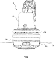
FIG. 2 is a plan view of a grass trimmer device of the grass trimmer ofFIG. 1 ; -
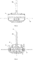
FIG. 3 is an inner view of the grass trimmer device ofFIG. 2 with a motor housing and a housing being opened; -
FIG. 4 is a plan view of a grass trimmer head and a motor shaft ofFIG. 3 ; -
FIG. 5 is a sectional view of a structure shown inFIG. 4 ; -
FIG. 6 is an exploded view of the structure shown inFIG. 4 ; -
FIG. 7 is a perspective view of the structure shown inFIG. 4 ; -
FIG. 8 is a top view of the structure shown inFIG. 4 ; -
FIG. 9 is a top view of the structure shown inFIG. 4 when an occlusal tooth is separated from an internal tooth and an external tooth; -
FIG. 10 is a top view of the structure shown inFIG. 4 when an occlusal tooth is engaged with an internal tooth; -
FIG. 11 is a top view of the structure shown inFIG. 4 when a movable block is engaged with an external tooth again after a certain angle is rotated; -
FIG. 12 is a control diagram of the grass trimmer ofFIG. 1 ; -
FIG. 13 is a graph illustrating a rotation speed of a motor of the grass trimmer ofFIG. 1 ; -
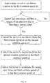
FIG. 14 is a flowchart of a control method for the grass trimmer ofFIG. 1 ; -
FIG. 15 is another graph of a rotation speed of a motor of the grass trimmer ofFIG. 1 ; and -
FIG. 16 is a flowchart of another control method for the grass trimmer ofFIG. 1 . - A
grass trimmer 100 shown inFIG. 1 includes anoperating device 11, agrass trimmer device 12, and aconnecting device 13. - The
operating device 11 includes ahandle 111, anauxiliary handle 112, and amain switch 113. Thehandle 111 and theauxiliary handle 112 are respectively used by two hands of a user to hold, so that the user can operate thegrass trimmer 100 more stably. Themain switch 113 may be disposed on thehandle 111. When the user holds thehandle 111, the user can directly operate themain switch 113 to control thegrass trimmer 100 to perform trimming. Theoperating device 11 may further include arear housing 114 for forming acoupling portion 114a, and thecoupling portion 114a is used for coupling a power supply device to power thegrass trimmer 100. For example, thecoupling portion 114a is capable of coupling a battery pack to power thegrass trimmer 100. Thehandle 111 may be integrally formed with therear housing 114, or thehandle 111 may be formed separately from therear housing 114. - As shown in
FIGS. 2 to 3 , thegrass trimmer device 12 includes agrass trimmer head 20, amotor 121 and amotor housing 122. Thegrass trimmer head 20 is used for trimming, and themotor 121 includes amotor shaft 121a for driving thegrass trimmer head 20 to rotate. Themotor shaft 121a can rotate about afirst axis 101, and themotor housing 122 is used for accommodating themotor 121. - The connecting
device 13 is used for connecting the operatingdevice 11 and thegrass trimmer device 12 so that the operatingdevice 11 and thegrass trimmer device 12 constitute a whole that can move together and form thegrass trimmer 100. Specifically, the connectingdevice 13 includes a connectingrod 131. One end of the connectingrod 131 is connected to themotor housing 122, and the other end of the connectingrod 131 may be connected to therear housing 114 of the operatingdevice 11. Theauxiliary handle 112 is also mounted to the connectingrod 131, and theauxiliary handle 112 may also be located between therear housing 114 and themotor housing 122. - The
grass trimmer device 12 further includes afan 123 which is at least partially disposed between themotor 121 and thegrass trimmer head 20. Thefan 123 is mounted to themotor shaft 121a and rotates together with themotor shaft 121a to dissipate heat from themotor 121. - The
grass trimmer head 20 further includes ahousing 21, aspool 22, agrass trimmer line 23 and aline feeding device 24. Anaccommodating cavity 211 is formed around thehousing 21. One side of thehousing 21 forming theaccommodating cavity 211 is an inner side of thehousing 21, and the other side of thehousing 21 opposite the inner side is an outer side. - As shown in
FIG. 4 to FIG. 8 , thehousing 21 may specifically include anupper housing portion 212 and alower housing portion 213, and theupper housing portion 212 and thelower housing portion 213 are integrally formed by a snap connection. Theupper housing portion 212 and thelower housing portion 213 are connected to form theaccommodating cavity 211 when connected. Thespool 22 is at least partially disposed in theaccommodating cavity 211, that is, thespool 22 is disposed inside thehousing 21. Thespool 22 is used for winding thegrass trimmer line 23 around, and thegrass trimmer line 23 is used for trimming. Thehousing 21 is further formed with anaperture 214 for thegrass trimmer line 23 to protrude to the outside of thehousing 21, and the number ofapertures 214 is two. The part of thegrass trimmer line 23 protruding through theapertures 214 to the outside of thehousing 21 is defined as aneffective part 231 of thegrass trimmer line 23. Theeffective part 231 of thegrass trimmer line 23 is capable of cutting weeds when rotating at a high speed. In order to achieve trimming a certain range of weeds, it is also expected that the length of theeffective part 231 of thegrass trimmer line 23 can reach a preset value, that is, the length of theeffective part 231 of thegrass trimmer line 23 is necessary to be greater than or equal to the preset value. The preset value of thegrass trimmer line 23 here may be a fixed value, or may of course be a variable value set by a user in advance. - The
line feeding device 24 is used for controlling whether thegrass trimmer head 20 is releasing the grass trimmer line. Theline feeding device 24 has a first working mode that makes thegrass trimmer head 20 unable to release the grass trimmer line, and the first working mode may also be considered as a trimming mode. Theline feeding device 24 also has a second working mode that enables thegrass trimmer head 20 to release the grass trimmer line, and the second working mode may also be considered as a grass trimmer line releasing mode. In response to determining that theline feeding device 24 is in the first working mode, thespool 22 and thehousing 21 are relatively stationary. In this way, thespool 22 and thehousing 21 will be driven by themotor shaft 121a to rotate synchronously, so that the length of theeffective part 231 of thegrass trimmer line 23 wound on thespool 22 at this time protruding outside thehousing 21 does not change, that is, thegrass trimmer line 23 cannot be released, and thegrass trimmer head 20 is in a normal working state at this time. In response to determining that theline feeding device 24 is in the second working mode, thespool 22 moves relative to thehousing 21, so that thegrass trimmer line 23 drives, under the action of the centrifugal force, thespool 22 to rotate relative to thehousing 21, so that thegrass trimmer line 23 is released, and the length of theeffective part 231 of thegrass trimmer line 23 will be increased. - In the present disclosure, as shown in
FIG. 12 , thegrass trimmer 100 further includes adetection device 14 and acontroller 15. Thedetection device 14 may be disposed on thegrass trimmer device 12 and thecontroller 15 may be disposed on the operatingdevice 11, and of course, the present disclosure is not limited thereto. Thedetection device 14 is configured to detect the length of theeffective part 231 of thegrass trimmer line 23. Specifically, thedetection device 14 detects a characterization parameter of thegrass trimmer 100 that can characterize the length of theeffective part 231 of thegrass trimmer line 23. For example, the characterization parameter may be the length of thegrass trimmer line 23 directly, or may also be the current flowing through themotor 121, or the torque of thegrass trimmer line 23, or the noise near thegrass trimmer head 20. When the length of theeffective part 231 of thegrass trimmer line 23 changes, the value of the characterization parameter detected by thedetection device 14 also changes accordingly, and when the length of theeffective part 231 of thegrass trimmer line 23 is less than the preset value described above, the value of the characterization parameter also changes to a corresponding value corresponding to the preset value. At this time, the change of the characterization parameter can reflect that the length of theeffective part 231 is less than or equal to the preset value. Thecontroller 15 is connected to thedetection device 14, and thedetection device 14 can send the detected value of the characterization parameter to thecontroller 15, and thecontroller 15 stores a correspondence relationship between the characterization parameter and the length of theeffective part 231. In this way, thecontroller 15 may compare a measured value of the received characterization parameter with a stored corresponding value. In response to determining that the characterization parameter reflects that the length of theeffective part 231 of thegrass trimmer line 23 is less than the preset value, thecontroller 15 controls theline feeding device 24 to switch to the second working mode, that is, to the grass trimmer line releasing mode. At this time, for thegrass trimmer line 23, the length of theeffective part 231 is increased under the action of the centrifugal force, and thereby the grass trimmer line is released; or in response to determining that the characterization parameter reflects that the length of theeffective part 231 of thegrass trimmer line 23 is equal to the preset value, thecontroller 15 controls theline feeding device 24 to switch to the second working mode. - Of course, if the
detection device 14 can directly detect the length of theeffective part 231, thedetection device 14 may directly send the detected length of theeffective part 231 to thecontroller 15. In this way, in response to determining that thecontroller 15 determines that the length of theeffective part 231 detected by thedetection device 14 is less than or equal to the preset value, theline feeding device 24 is controlled to switch to the second working mode. Alternatively, thedetection device 14 may be not required to detect the length of theeffective part 231 of thegrass trimmer line 23, but directly detect whether the length of theeffective part 231 of thegrass trimmer line 23 is less than or equal to a preset value, for example, thedetection device 14 can emit a beam of laser line passing through thegrass trimmer line 23, and the intersection between the laser line and thegrass trimmer line 23 is exactly the position of the preset value of theeffective part 231 of thegrass trimmer line 23. If the laser beam is obstructed by thegrass trimmer line 23, it can be determined that the length of theeffective part 231 is greater than or equal to the preset value. If the laser beam is not obstructed by thegrass trimmer line 23, it can be determined that the length of theeffective part 231 is less than the preset value. - In this embodiment, as shown in
FIGS. 3 to 7 , theline feeding device 24 specifically includes amovable block 241 disposed between thespool 22 and thehousing 21. In this embodiment, themotor shaft 121a and thespool 22 rotate synchronously. For example, in this embodiment, themotor shaft 121a is in flat fit with thespool 22. When themotor 121 operates, themotor shaft 121a is capable of driving thespool 22 to rotate synchronously with themotor shaft 121a itself. Themovable block 241 is formed with atransmission hole 241a. Through thetransmission hole 241a, themovable block 241 is sleeved on thespool 22, and can respond to the rotation of thespool 22 to rotate synchronously with thespool 22. Themovable block 241 is asymmetric about thefirst axis 101 in mass distribution. Further, the center of gravity G of themovable block 241 deviates from thefirst axis 101. A biasingmember 242 is further provided between themovable block 241 and thespool 22, and the biasingmember 242 is specifically a coil spring. Specifically, anaccommodating groove 221 is extendingly formed on thespool 22, and the coil spring is at least partially disposed in theaccommodating groove 221. One end of the coil spring abuts against the groove bottom of theaccommodating groove 221, and the other end of the coil spring abuts against themovable block 241. The center of gravity of themovable block 241 and the biasingmember 242 are disposed on two sides of a plane passing through thefirst axis 101 and perpendicular to a firststraight line 102. Themovable block 241 is also slidably connected to thespool 22. When themovable block 241 rotates with thespool 22, themovable block 241 will generate a centrifugal force. At the same time, themovable block 241 is subjected to a biasing force of the biasingmember 242. The directions of the biasing force and the centrifugal force are opposite. Further, the directions of the centrifugal force and the biasing force may both be in the direction of the firststraight line 102, and the direction in which themovable block 241 is slidably connected to thespool 22 may also be along the direction of the firststraight line 102. When themotor 121 operates at a first rotation speed n1 that enables thegrass trimmer 100 to be in a normal trimming state, the biasing force of the biasingmember 242 on themovable block 241 can be balanced with the centrifugal force generated by themovable block 241, so that themovable block 241 at this time is stationary relative to thespool 22; and when themotor 121 accelerates from the first rotation speed n1, the biasing force of the biasingmember 242 on themovable block 241 will be insufficient to be balanced with the centrifugal force generated by themovable block 241, so that themovable block 241 will slide, under the action of the centrifugal force, in the direction of the firststraight line 102 relative to thespool 22. - In this embodiment, the
housing 21 is formed with the aboveaccommodating cavity 211 around thefirst axis 101, thespool 22 is disposed in theaccommodating cavity 211 formed by thehousing 21, and themovable block 241 is partially located in theaccommodating cavity 211 and partially protrudes outside theaccommodating cavity 211. Specifically, one end of thehousing 21 facing toward themotor 121 along the direction of thefirst axis 101 is formed with anupper bottom portion 215, themotor shaft 121a penetrates theupper bottom portion 215 into theaccommodating cavity 211, and themovable block 241 partially protrudes outside thehousing 21. Theupper bottom portion 215 facing toward themotor 121 is formed with aninner ring 216 and anouter ring 217, and theinner ring 216 and theouter ring 217 are both formed around thefirst axis 101. Theinner ring 216 is formed around thefirst axis 101 with acentral hole 26a through which themotor shaft 121a passes, and themovable block 241 is at least partially disposed in thecentral hole 26a. Theinner ring 216 protrudes toward theouter ring 217 to formexternal teeth 216a, and theouter ring 217 protrudes toward theinner ring 216 to forminternal teeth 217a. Multipleinternal teeth 217a are provided, and multipleexternal teeth 216a are provided. In the circumferential direction around thefirst axis 101, theinternal tooth 217a and theexternal tooth 216a are staggered from each other, that is, theinternal tooth 217a and theexternal tooth 216a are not disposed in the same diameter direction perpendicular to thefirst axis 101. Themovable block 241 is formed with an engagement portion that can cooperate with theinternal tooth 217a or theexternal tooth 216a. The engagement portion is specifically anocclusal tooth 241b. In this case, theinternal tooth 217a and theexternal tooth 216a are a reception portion for receiving theocclusal tooth 241b. As shown inFIG. 7 and FIG. 8 , when theocclusal tooth 241b of themovable block 241 is engaged with theexternal tooth 216a or theinternal tooth 217a, themovable block 241 makes thehousing 21 stationary relative to thespool 22. That is, no relative movement exists between thespool 22 and thehousing 21 at this time, it can be considered that theline feeding device 24 at this time is in the first working mode, and thegrass trimmer 100 is in a normal trimming state. As shown inFIG. 9 , when theocclusal tooth 241b of themovable block 241 is detached from theexternal tooth 216a or theexternal tooth 216a, themovable block 241 is in a free state relative to thehousing 21, and thespool 22 is also in a free state relative to thehousing 21. That is to say, at this time, thespool 22 can move relative to thehousing 21, and it can be considered that theline feeding device 24 is in the second working mode at this time, that is, in the grass trimmer line releasing mode. At this time, thespool 22 can move relative to thehousing 21 under the action of the centrifugal force of thegrass trimmer line 23, so that the length of theeffective part 231 of thegrass trimmer line 23 protruding outside of thehousing 21 can be increased. - When the
motor 121 drives, at the first rotation speed n1, thespool 22 to rotate, themovable block 241, under the action of the biasing force of the biasingmember 242, causes theocclusal tooth 241b to be engaged with theexternal tooth 216a on theinner ring 216, so that theline feeding device 24 is in the first working mode, thehousing 21 is stationary relative to thespool 22, and the length of theeffective part 231 of thegrass trimmer line 23 protruding outside thehousing 21 is fixed; when themotor 121 accelerates from the first rotation speed n1, the centrifugal force generated by themovable block 241 will overcome the biasing force of the biasingmember 242 on themovable block 241, and themovable block 24 will slide relative to thespool 22 along the firststraight line 102 to make theocclusal tooth 241b detached from theexternal tooth 216a on theinner ring 216. At this time, thehousing 21 will not be driven by themovable block 241, which makes theline feeding device 24 is in the second working mode, so that thespool 22 can move relative to thehousing 21 at this time, and then the length of theeffective part 231 of thegrass trimmer line 23 is increased under the action of the centrifugal force to achieve the purpose of releasing the grass trimmer line. - In response to determining that the
detection device 14 detects that the length of theeffective part 231 of thegrass trimmer line 23 is less than the preset value, theline feeding device 24 can switch to the second working mode, so that thecontroller 15 is also connected to thedetection device 14. In this way, in response to determining that thedetection device 14 detects that the length of theeffective part 231 of thegrass trimmer line 23 is less than the preset value, thecontroller 15 controls themotor 121 to accelerate from the first rotation speed n1, and when themotor 121 accelerates, theline feeding device 24 can switch to the second working mode. At this time, under the action of the centrifugal force, the length of theeffective part 231 of thegrass trimmer line 23 is increased to achieve the purpose of releasing the grass trimmer line. After theocclusal tooth 241b of themovable block 241 is detached from theexternal tooth 216a on theinner ring 216, as shown inFIG. 9 , themovable block 241 can rotate with thespool 22 relative to thehousing 21, and at the same time, themovable block 241 will also slide relative to thespool 22 along the direction of the firststraight line 102. The sliding of themovable block 241 relative to thespool 22 and the rotation of themovable block 241 relative to thehousing 21 cause a change in the position of themovable block 241 relative to thehousing 21 in the circumferential direction around thefirst axis 101, and also cause a change in the position of themovable block 241 relative to thehousing 21 in the diameter direction perpendicular to thefirst axis 101, as shown inFIG. 10 , which enables themovable block 241 to move to a position where theocclusal tooth 241b is engaged with aninternal tooth 217a after theocclusal tooth 241b is detached from theexternal tooth 216a. At this time, themovable block 241 makes thehousing 21 stationary relative to thespool 22. Then, thecontroller 15 can control themotor 121 to decelerate. After themotor 121 decelerates, themovable block 241 will be reset under the action of the biasing force and finally reset to the state in which theocclusal tooth 241b is engaged with anotherinternal tooth 217a as shown inFIG. 11 . The process in which themovable block 241 moves from the engagement of theocclusal tooth 241b with oneexternal tooth 216a to the engagement of theocclusal tooth 241b with oneinternal tooth 217a may be considered as theline feeding device 24 being in the second working mode. In this process, the whole formed by themovable block 241 and thespool 22 rotate a first angle A1 relative to thehousing 21 and the first angle A1 may be greater than 40 degrees; and in the process in which themovable block 241 is reset from the engagement of theocclusal tooth 241b with theinternal tooth 217a to the engagement of themovable block 241 with anotherexternal tooth 216a, themovable block 241 and thespool 22 rotate a second angle A2 relative to thehousing 21. The second angle A2 is smaller than the first angle A1, and the difference between the second angle A2 and the first angle A1 may be more than 30 degrees. Specifically, the second angle A2 is smaller than 20 degrees, which makes the length of theeffective part 231 of thegrass trimmer line 23 protruding outsidehousing 21 not be increased or increase less. - As shown in
FIGS. 1 ,13 and14 , a control method for agrass trimmer 100 includes the steps described below. - The
motor 121 is started by themain switch 113 to accelerate to the first rotation speed n1. When the user triggers themain switch 113, themotor 121 starts to accelerate. After a period of time of t1, themotor 121 accelerates to the first rotation speed n1, and then themotor 121 will operate at the first rotation speed n1. At this time, theline feeding device 24 is in the first working mode, thespool 22 and thehousing 21 are in a relatively stationary state, and thegrass trimmer 100 is in the normal trimming state. - It is detected and determined whether the length of the
effective part 231 is less than a preset value. Specifically, thedetection device 14 may directly detect the length of theeffective part 231 of thegrass trimmer line 23 and then send the length to thecontroller 15. Thecontroller 15 determines whether the length of theeffective part 231 is less than the preset value. If the length of theeffective part 231 is less than the preset value, the process proceeds to the next step, otherwise, the detection is continued. Alternatively, thedetection device 14 may also directly detect and determine whether the length of theeffective part 231 is less than the preset value without detecting the specific value of the length of theeffective part 231. For example, thedetection device 14 can emit a beam of laser line that can pass through thegrass trimmer line 23. The intersection between the laser line and thegrass trimmer line 23 is exactly the position of the preset value of theeffective part 231 of thegrass trimmer line 23. If the laser line and thegrass trimmer line 23 do not have the intersection, the laser line will not be obstructed by thegrass trimmer line 23. At this time, it can be determined that the length of theeffective part 231 of thegrass trimmer line 23 is less than the preset value. If the laser line and thegrass trimmer line 23 have the intersection, the laser line is obstructed by thegrass trimmer line 23 to make the light intensity of the laser line to be weakened. It can be determined that the length of thegrass trimmer line 23 is greater than or equal to the preset value. In this embodiment, those skilled in the art can understand that it may also be detected and determined whether the length of theeffective part 231 is equal to the preset value for accurate detection and determination. - The
motor 121 is controlled to accelerate from the first rotation speed n1 to the second rotation speed n2. After thegrass trimmer 100 starts trimming for a period of time from time t1, that is, to time t2, the length of theeffective part 231 of thegrass trimmer line 23 is less than or equal to the preset value at time t2 due to wear and tear. Thecontroller 15 controls themotor 121 to accelerate to the second rotation speed n2 at this time, so that theline feeding device 24 switches to the second working mode, that is, to the grass trimmer line releasing mode, so that the length of theeffective part 231 of thegrass trimmer line 23 will be increased. As shown inFIG. 15 , thecontroller 15 may also control themotor 121 to accelerate to the second rotation speed n2, and to operate at the second rotation speed n2 for Δt time, so as to ensure that the length of thegrass trimmer line 23 released can reach the user demand. - The
motor 121 is controlled to decelerate from the second rotation speed n2 to the third rotation speed n3. When themotor 121 accelerates to the second rotation speed n2 at time t3, thegrass trimmer line 23 has completed the grass trimmer line releasing work. At this time, thecontroller 15 controls themotor 121 to start deceleration and decelerate to the third rotation speed n3 at time t4. The third rotation speed n3 is smaller than the second rotation speed n2, and the third rotation speed n3 is smaller than or equal to the first rotation speed n1. In this embodiment, further, the third rotation speed n3 is smaller than the first rotation speed n1, so that the biasing force of the biasingmember 242 on themovable block 241 can be greater than the centrifugal force received by themovable block 241, so that themovable block 241 can be quickly reset. The first rotation speed n1 is greater than 5000 rpm, the second rotation speed n2 is greater than 6000 rpm, and the third rotation speed n3 is smaller than 3000 rpm. The difference between the third rotation speed n3 and the second rotation speed n2 is also greater than the difference between the second rotation speed n2 and the first rotation speed n1, which can further ensure that themovable block 241 can be quickly reset. - The
motor 121 is controlled to accelerate for being reset from the third rotation speed n3 to the first rotation speed n1. Finally, thecontroller 15 can control themotor 121 to reset to the first rotation speed n1, and then, thegrass trimmer 100 continues trimming. - As shown in
FIG. 16 , the control method for thegrass trimmer 100 may also include the steps described below. - The
main switch 113 is started to accelerate themotor 121 to the first rotation speed n1. - The magnitude of the characterization parameter that reflects the length of the
effective part 231 of thegrass trimmer line 23 is detected. In this embodiment, thedetection device 14 can detect the magnitude of the characterization parameter capable of reflecting the length of theeffective part 231 of thegrass trimmer line 23, thereby achieving indirect measurement of the length of theeffective part 231 of thegrass trimmer line 23. The characterization parameter may be a current flowing through themotor 121, a torque of thegrass trimmer line 23, or a noise near thegrass trimmer head 20. - It is determined whether the length of the
effective part 231 is less than the preset value. Thedetection device 14 sends the measured characterization parameter to thecontroller 15, and thecontroller 15 compares the measured value of the characterization parameter with a stored corresponding value corresponding to the length of theeffective part 231. If the value of the characterization parameter can reflect the length of theeffective part 231 is less than the preset value, the process proceeds to the next step, otherwise, the process returns to the previous step. In this embodiment, those skilled in the art can understand that it may also be detected and determined whether the length of theeffective part 231 is equal to a preset value for accurate detection and determination. - The
motor 121 is controlled to accelerate from the first rotation speed n1 to the second rotation speed n2. Similarly, in this embodiment, thecontroller 15 can also control themotor 121 to accelerate to the second rotation speed n2, and to operate at the second rotation speed n2 for a period of time, thereby ensuring the length of thegrass trimmer line 23 released satisfy the needs for use. - The
motor 121 is controlled to decelerate from the second rotation speed n2 to the third rotation speed n3. - The
motor 121 is controlled to accelerate for being reset from the third rotation speed n3 to the first rotation speed n1. - The basic principles, main features, and advantages of the present disclosure have been shown and described above. Those skilled in the art should understand that the above embodiments do not limit the present disclosure in any form, and that any technical solution obtained by means of equivalent substitution or equivalent transformation falls within the protection scope of the present disclosure.
- The present disclosure provides a grass trimmer and a control method thereof, which enables the grass trimmer to achieve intelligent and automatic grass trimmer line releasing.
Claims (17)
- A grass trimmer, comprising:an operating device configured for a user to operate; anda grass trimmer device comprising a grass trimmer head and a motor configured to drive the grass trimmer head;wherein the grass trimmer head comprises:a spool configured for a grass trimmer line winding around and capable of rotating around a first axis; anda housing formed with an accommodating cavity configured to accommodate at least a part of the spool and formed with an aperture configured for the grass trimmer line to pass through;wherein when the grass trimmer is mounted with the grass trimmer line, a part of the grass trimmer line protruding outside the housing is defined as an effective part of the grass trimmer line;wherein the grass trimmer further comprises:
a controller configured to control the grass trimmer head to release the grass trimmer line when the grass trimmer head is mounted with the grass trimmer line and a length of the effective part is detected to be less than or equal to a preset value. - The grass trimmer of claim 1, further comprising:a line feeding device configured to have a first working mode for preventing the grass trimmer head from releasing the grass trimmer line and a second working mode for allowing the grass trimmer head to release the grass trimmer line;wherein when the line feeding device is in the first working mode, the housing is stationary relative to the spool, and the grass trimmer head is capable of trimming grass; andwherein when the line feeding device is in the second working mode, the spool rotates relative to the housing, and the grass trimmer head releases the grass trimmer line.
- The grass trimmer of claim 2, wherein the controller is connected to the motor, and the controller is at least capable of switching the grass trimmer head from the first working mode to the second working mode by controlling the motor to be accelerated by a first rotation speed at which the grass trimmer is in a normal trimming state.
- The grass trimmer of claim 1, further comprising:a detection device configured to detect a characterization parameter that reflects a change in the length of the effective part when the grass trimmer line is mounted to the grass trimmer;wherein the controller is connected to the detection device, and when the characterization parameter reflects that the length of the effective part is less than or equal to the preset value, the controller controls the grass trimmer head to release the grass trimmer line.
- The grass trimmer of claim 4, wherein a correspondence relationship between the characterization parameter and the length of the effective part is stored in the controller.
- The grass trimmer of claim 5, wherein the characterization parameter is a current flowing through the motor, or a torque of the grass trimmer line, or a noise outside the housing of the grass trimmer head.
- The grass trimmer of claim 1, further comprising:a line feeding device configured to have a first working mode for preventing the grass trimmer head from releasing the grass trimmer line and a second working mode for allowing the grass trimmer head to release the grass trimmer line;wherein the line feeding device comprises:a movable block capable of rotating with rotation of the spool and sliding along a direction of a first straight line relative to the spool;wherein the movable block is formed with an engagement portion, and the housing is formed with a reception portion capable of cooperating with the engagement portion to cause the housing and the spool relatively stationary;wherein when the line feeding device is in the first working mode, the movable block slides to a position where the engagement portion and the reception portion cooperate with each other; andwherein when the line feeding device is in the second working mode, the movable block slides to a position where the engagement portion and the reception portion are separated from each other.
- The grass trimmer of claim 7, wherein the reception portion is formed on an outer side of the housing facing toward the motor, and the movable block is at least partially disposed outside the accommodating cavity.
- The grass trimmer of claim 7, wherein the line feeding device comprises:
a biasing member configured to bias the movable block to move toward the position where the engagement portion and the reception portion cooperate with each other. - The grass trimmer of claim 9, wherein a center of gravity of the movable block and the biasing member are respectively disposed on two sides of a plane passing through the first axis and perpendicular to the first straight line.
- The grass trimmer of claim 1, further comprising:a detection device configured to detect the length of the effective part;wherein the detection device is connected to the controller, and when the length of the effective part detected by the detection device is less than or equal to the preset value, the controller controls the grass trimmer head to release the grass trimmer line.
- The grass trimmer of claim 1, further comprising:a detection device configured to detect whether the length of the effective part is less than or equal to the preset value;wherein the controller is connected to the detection device, and in response to determining that the detection device detects that the length of the effective part is less than or equal to the preset value, the controller controls the grass trimmer head to release the grass trimmer line.
- A control method for a grass trimmer, wherein the grass trimmer comprises a grass trimmer device, the grass trimmer device comprises a grass trimmer head and a motor configured to drive the grass trimmer head to rotate, the grass trimmer line is driven to rotate to cut grass when the grass trimmer head is mounted with a grass trimmer line; when the grass trimmer head is mounted with the grass trimmer line, a part of the grass trimmer line protruding outside the grass trimmer head is defined as an effective part of the grass trimmer line;
wherein the control method comprises steps of:detecting and determining whether a length of the effective part is less than or equal to a preset value; andin response to determining that the length of the effective part is less than or equal to the preset value, controlling the grass trimmer head to release a grass trimmer line. - The control method of claim 13, wherein when the length of the effective part is less than or equal to the preset value, the motor is controlled to accelerate from a first rotation speed to a second rotation speed to cause the grass trimmer head to release the grass trimmer line.
- The control method of claim 14, wherein further comprising a step of:
controlling the motor to decelerate from the second rotation speed to a third rotation speed. - The control method of claim 15, wherein the third rotation speed is smaller than the first rotation speed.
- The control method of claim 15, wherein a difference between the third rotation speed and the second rotation speed is greater than a difference between the second rotation speed and the first rotation speed.
Applications Claiming Priority (3)
| Application Number | Priority Date | Filing Date | Title |
|---|---|---|---|
| CN201710985907 | 2017-10-20 | ||
| CN201711439441 | 2017-12-27 | ||
| PCT/CN2018/110927 WO2019076354A1 (en) | 2017-10-20 | 2018-10-19 | Grass trimmer and control method therefor |
Publications (3)
| Publication Number | Publication Date |
|---|---|
| EP3679780A1 true EP3679780A1 (en) | 2020-07-15 |
| EP3679780A4 EP3679780A4 (en) | 2021-01-06 |
| EP3679780B1 EP3679780B1 (en) | 2023-09-20 |
Family
ID=66174300
Family Applications (1)
| Application Number | Title | Priority Date | Filing Date |
|---|---|---|---|
| EP18868343.7A Active EP3679780B1 (en) | 2017-10-20 | 2018-10-19 | Grass trimmer and control method therefor |
Country Status (4)
| Country | Link |
|---|---|
| US (1) | US11937537B2 (en) |
| EP (1) | EP3679780B1 (en) |
| CN (2) | CN109691290B (en) |
| WO (1) | WO2019076354A1 (en) |
Families Citing this family (19)
| Publication number | Priority date | Publication date | Assignee | Title |
|---|---|---|---|---|
| CN109691290B (en) * | 2017-10-20 | 2021-03-02 | 南京德朔实业有限公司 | Grass trimmer |
| EP3973761B1 (en) * | 2019-06-17 | 2025-02-19 | Nanjing Chervon Industry Co., Ltd. | Grass trimmer and grass trimming head thereof |
| CN117918110A (en) * | 2022-10-13 | 2024-04-26 | 南京泉峰科技有限公司 | Grass mowing head and grass mowing machine |
| USD960670S1 (en) * | 2019-12-27 | 2022-08-16 | The Toro Company | Handle for lawn and garden tool |
| WO2021257954A1 (en) | 2020-06-19 | 2021-12-23 | Milwaukee Electric Tool Corporation | String trimmer |
| CN114246051B (en) * | 2020-09-25 | 2023-09-08 | 南京泉峰科技有限公司 | Mower and control method thereof |
| CN112772108B (en) * | 2021-02-01 | 2023-03-31 | 上海筱珈数据科技有限公司 | Lawn robot-based grass cutting method |
| CN217742287U (en) * | 2021-04-12 | 2022-11-08 | 南京泉峰科技有限公司 | Grass trimmer |
| WO2022225853A1 (en) | 2021-04-19 | 2022-10-27 | Milwaukee Electric Tool Corporation | String trimmer head |
| CN113179742A (en) * | 2021-05-19 | 2021-07-30 | 宁波奥晟机械有限公司 | Grass and brush cutter |
| DE212022000197U1 (en) | 2021-06-30 | 2024-02-19 | Milwaukee Electric Tool Corporation | String trimmer assembly and trimmer head for use with it |
| WO2023278734A1 (en) | 2021-06-30 | 2023-01-05 | Milwaukee Electric Tool Corporation | String trimmer head |
| CN115685979B (en) * | 2021-07-23 | 2025-07-15 | 苏州宝时得电动工具有限公司 | Automatic walking device and method for retracting and releasing self-driven hose |
| USD1074339S1 (en) * | 2021-10-29 | 2025-05-13 | Jiangsu Dongcheng Tools Technology Co., Ltd. | Lawn mower |
| US12477978B2 (en) | 2022-03-18 | 2025-11-25 | Techtronic Cordless Gp | Power tool and accessory mount device |
| US20230389470A1 (en) * | 2022-06-07 | 2023-12-07 | Milwaukee Electric Tool Corporation | Trimmers and auto advancing trimmer lines |
| CN115250721B (en) * | 2022-08-25 | 2026-04-17 | 浙江动一新能源动力科技股份有限公司 | Grass trimmer head, work head and grass trimmer |
| USD1101524S1 (en) * | 2022-08-25 | 2025-11-11 | Nanjing Chervon Industry Co., Ltd. | String trimmer head |
| US12532806B2 (en) | 2023-02-14 | 2026-01-27 | Techtronic Cordless Gp | Power tool and compact power feed trimmer head |
Family Cites Families (25)
| Publication number | Priority date | Publication date | Assignee | Title |
|---|---|---|---|---|
| US4852258A (en) * | 1981-03-19 | 1989-08-01 | White Consolidated Industries, Inc. | Apparatus for cutting vegetation |
| US5276968A (en) * | 1978-03-30 | 1994-01-11 | White Consolidated Industries, Inc. | Apparatus for cutting vegetation |
| ZA878894B (en) * | 1986-12-17 | 1988-09-28 | White Consolidated Ind Inc | Line feed mechanism for line trimmers |
| US5020223A (en) * | 1989-11-02 | 1991-06-04 | White Consolidated Industries, Inc. | Simplified bump-feed type cutting head assembly for flexible line trimmers |
| US5109607A (en) * | 1990-10-12 | 1992-05-05 | Inertia Dynamics Corporation | Automatic line trimmer head |
| DE19719489C2 (en) * | 1997-05-07 | 1999-04-15 | Wolf Garten Gmbh & Co Kg | Thread cutter |
| CN2459863Y (en) * | 2000-12-04 | 2001-11-21 | 苏州太湖企业有限公司 | Automatic paying-out mechanism of mower |
| DE102007015991B4 (en) * | 2006-04-21 | 2026-05-21 | Andreas Stihl Ag & Co. Kg | Hand-held work tool with an electric drive motor |
| CN101982036B (en) * | 2010-08-27 | 2012-11-07 | 浙江亚特电器有限公司 | Grass head mowing structure for knocking type thread outlet grass mowing machine |
| EP2798935B1 (en) * | 2013-05-03 | 2018-03-07 | Black & Decker Inc. | Vegetation cutting device |
| EP2798934B1 (en) * | 2013-05-03 | 2018-02-21 | Black & Decker Inc. | Vegetation cutting device |
| CN203301992U (en) * | 2013-06-14 | 2013-11-27 | 宁波鑫迪电机科技有限公司 | Grass trimmer with front motor |
| CN104663113B (en) * | 2013-11-28 | 2016-08-31 | 苏州宝时得电动工具有限公司 | A kind of rotary grass-mowing machine |
| CN105815028B (en) * | 2014-05-30 | 2017-12-01 | 苏州宝时得电动工具有限公司 | The line-putting method of grass-mowing machine and grass-mowing machine |
| US10314228B2 (en) * | 2014-05-16 | 2019-06-11 | Positec Power Tools (Suzhou) Co., Ltd. | Grass trimmer and cord delivering method of grass trimmer |
| EP3014975B1 (en) * | 2014-10-31 | 2018-05-23 | Robert Bosch Gmbh | Garden device and method for its operation |
| US20160183452A1 (en) * | 2014-12-29 | 2016-06-30 | Husqvarna Ab | Quick loading trimmer head |
| WO2017059917A1 (en) | 2015-10-08 | 2017-04-13 | Husqvarna Ab | Automatic line feed for trimmer |
| CN106993426B (en) * | 2016-01-22 | 2019-03-08 | 南京德朔实业有限公司 | lawn mower |
| CN107996122A (en) * | 2016-10-28 | 2018-05-08 | 苏州宝时得电动工具有限公司 | Grass-mowing machine and its line-putting method |
| CN206506877U (en) * | 2016-12-06 | 2017-09-22 | 苏州宝时得电动工具有限公司 | Grass-mowing machine |
| CN108617226A (en) * | 2017-03-23 | 2018-10-09 | 苏州宝时得电动工具有限公司 | Grass-mowing machine |
| CN109691290B (en) * | 2017-10-20 | 2021-03-02 | 南京德朔实业有限公司 | Grass trimmer |
| WO2019158008A1 (en) * | 2018-02-14 | 2019-08-22 | 南京德朔实业有限公司 | Grass trimmer, trimming head thereof and winding control method therefor |
| CN115605076B (en) * | 2020-04-01 | 2025-10-31 | 胡斯华纳有限公司 | Feed control of the lawn mowing line |
-
2018
- 2018-10-18 CN CN201811211844.5A patent/CN109691290B/en active Active
- 2018-10-18 CN CN201811211822.9A patent/CN109691289B/en active Active
- 2018-10-19 EP EP18868343.7A patent/EP3679780B1/en active Active
- 2018-10-19 WO PCT/CN2018/110927 patent/WO2019076354A1/en not_active Ceased
-
2020
- 2020-04-10 US US16/845,465 patent/US11937537B2/en active Active
Also Published As
| Publication number | Publication date |
|---|---|
| US11937537B2 (en) | 2024-03-26 |
| EP3679780A4 (en) | 2021-01-06 |
| CN109691289B (en) | 2020-10-23 |
| CN109691290A (en) | 2019-04-30 |
| EP3679780B1 (en) | 2023-09-20 |
| WO2019076354A1 (en) | 2019-04-25 |
| US20200236845A1 (en) | 2020-07-30 |
| CN109691289A (en) | 2019-04-30 |
| CN109691290B (en) | 2021-03-02 |
Similar Documents
| Publication | Publication Date | Title |
|---|---|---|
| EP3679780B1 (en) | Grass trimmer and control method therefor | |
| US11818979B2 (en) | Grass trimmer | |
| US11419262B2 (en) | Grass trimmer | |
| US10440882B2 (en) | Grass trimmer, operating method thereof and control method thereof | |
| US12557730B2 (en) | Grass trimmer | |
| US20180092297A1 (en) | Working machine and method for determining abnormal state of working machine | |
| CN107996122A (en) | Grass-mowing machine and its line-putting method | |
| US20240399556A1 (en) | Mode selection of a power tool | |
| EP3025573B1 (en) | Line feed mechanism for string trimmer | |
| CN112088640B (en) | Grass trimmer | |
| JP5900782B2 (en) | Electric tool | |
| US20190308309A1 (en) | Power tool and method for detecting engagement of interchangeable tool implement with tool body | |
| JP2021512594A (en) | Trimmer head and trimmer | |
| US10532454B2 (en) | Electric working machine | |
| EP3141356B1 (en) | Electric scissors | |
| WO2021220992A1 (en) | Work machine | |
| JP2013165676A (en) | Electric working machine | |
| JP5304199B2 (en) | Engine working machine | |
| US12544942B2 (en) | Cutting device | |
| JP6675259B2 (en) | Electric work machine | |
| JP2013165678A (en) | Electric working machine | |
| JP5877496B2 (en) | Electric working machine | |
| JP7625804B2 (en) | Power Tools |
Legal Events
| Date | Code | Title | Description |
|---|---|---|---|
| STAA | Information on the status of an ep patent application or granted ep patent |
Free format text: STATUS: THE INTERNATIONAL PUBLICATION HAS BEEN MADE |
|
| PUAI | Public reference made under article 153(3) epc to a published international application that has entered the european phase |
Free format text: ORIGINAL CODE: 0009012 |
|
| STAA | Information on the status of an ep patent application or granted ep patent |
Free format text: STATUS: REQUEST FOR EXAMINATION WAS MADE |
|
| 17P | Request for examination filed |
Effective date: 20200408 |
|
| AK | Designated contracting states |
Kind code of ref document: A1 Designated state(s): AL AT BE BG CH CY CZ DE DK EE ES FI FR GB GR HR HU IE IS IT LI LT LU LV MC MK MT NL NO PL PT RO RS SE SI SK SM TR |
|
| AX | Request for extension of the european patent |
Extension state: BA ME |
|
| A4 | Supplementary search report drawn up and despatched |
Effective date: 20201207 |
|
| RIC1 | Information provided on ipc code assigned before grant |
Ipc: A01D 75/28 20060101ALI20201201BHEP Ipc: A01D 34/416 20060101AFI20201201BHEP Ipc: A01D 34/00 20060101ALI20201201BHEP |
|
| DAV | Request for validation of the european patent (deleted) | ||
| DAX | Request for extension of the european patent (deleted) | ||
| STAA | Information on the status of an ep patent application or granted ep patent |
Free format text: STATUS: EXAMINATION IS IN PROGRESS |
|
| 17Q | First examination report despatched |
Effective date: 20210818 |
|
| GRAP | Despatch of communication of intention to grant a patent |
Free format text: ORIGINAL CODE: EPIDOSNIGR1 |
|
| STAA | Information on the status of an ep patent application or granted ep patent |
Free format text: STATUS: GRANT OF PATENT IS INTENDED |
|
| GRAS | Grant fee paid |
Free format text: ORIGINAL CODE: EPIDOSNIGR3 |
|
| GRAA | (expected) grant |
Free format text: ORIGINAL CODE: 0009210 |
|
| STAA | Information on the status of an ep patent application or granted ep patent |
Free format text: STATUS: THE PATENT HAS BEEN GRANTED |
|
| INTG | Intention to grant announced |
Effective date: 20230725 |
|
| AK | Designated contracting states |
Kind code of ref document: B1 Designated state(s): AL AT BE BG CH CY CZ DE DK EE ES FI FR GB GR HR HU IE IS IT LI LT LU LV MC MK MT NL NO PL PT RO RS SE SI SK SM TR |
|
| REG | Reference to a national code |
Ref country code: GB Ref legal event code: FG4D |
|
| REG | Reference to a national code |
Ref country code: CH Ref legal event code: EP |
|
| REG | Reference to a national code |
Ref country code: IE Ref legal event code: FG4D |
|
| REG | Reference to a national code |
Ref country code: DE Ref legal event code: R096 Ref document number: 602018058049 Country of ref document: DE |
|
| REG | Reference to a national code |
Ref country code: LT Ref legal event code: MG9D |
|
| PG25 | Lapsed in a contracting state [announced via postgrant information from national office to epo] |
Ref country code: GR Free format text: LAPSE BECAUSE OF FAILURE TO SUBMIT A TRANSLATION OF THE DESCRIPTION OR TO PAY THE FEE WITHIN THE PRESCRIBED TIME-LIMIT Effective date: 20231221 |
|
| REG | Reference to a national code |
Ref country code: NL Ref legal event code: MP Effective date: 20230920 |
|
| PG25 | Lapsed in a contracting state [announced via postgrant information from national office to epo] |
Ref country code: SE Free format text: LAPSE BECAUSE OF FAILURE TO SUBMIT A TRANSLATION OF THE DESCRIPTION OR TO PAY THE FEE WITHIN THE PRESCRIBED TIME-LIMIT Effective date: 20230920 Ref country code: RS Free format text: LAPSE BECAUSE OF FAILURE TO SUBMIT A TRANSLATION OF THE DESCRIPTION OR TO PAY THE FEE WITHIN THE PRESCRIBED TIME-LIMIT Effective date: 20230920 Ref country code: NO Free format text: LAPSE BECAUSE OF FAILURE TO SUBMIT A TRANSLATION OF THE DESCRIPTION OR TO PAY THE FEE WITHIN THE PRESCRIBED TIME-LIMIT Effective date: 20231220 Ref country code: LV Free format text: LAPSE BECAUSE OF FAILURE TO SUBMIT A TRANSLATION OF THE DESCRIPTION OR TO PAY THE FEE WITHIN THE PRESCRIBED TIME-LIMIT Effective date: 20230920 Ref country code: LT Free format text: LAPSE BECAUSE OF FAILURE TO SUBMIT A TRANSLATION OF THE DESCRIPTION OR TO PAY THE FEE WITHIN THE PRESCRIBED TIME-LIMIT Effective date: 20230920 Ref country code: HR Free format text: LAPSE BECAUSE OF FAILURE TO SUBMIT A TRANSLATION OF THE DESCRIPTION OR TO PAY THE FEE WITHIN THE PRESCRIBED TIME-LIMIT Effective date: 20230920 Ref country code: GR Free format text: LAPSE BECAUSE OF FAILURE TO SUBMIT A TRANSLATION OF THE DESCRIPTION OR TO PAY THE FEE WITHIN THE PRESCRIBED TIME-LIMIT Effective date: 20231221 Ref country code: FI Free format text: LAPSE BECAUSE OF FAILURE TO SUBMIT A TRANSLATION OF THE DESCRIPTION OR TO PAY THE FEE WITHIN THE PRESCRIBED TIME-LIMIT Effective date: 20230920 |
|
| REG | Reference to a national code |
Ref country code: AT Ref legal event code: MK05 Ref document number: 1612645 Country of ref document: AT Kind code of ref document: T Effective date: 20230920 |
|
| PG25 | Lapsed in a contracting state [announced via postgrant information from national office to epo] |
Ref country code: NL Free format text: LAPSE BECAUSE OF FAILURE TO SUBMIT A TRANSLATION OF THE DESCRIPTION OR TO PAY THE FEE WITHIN THE PRESCRIBED TIME-LIMIT Effective date: 20230920 |
|
| PG25 | Lapsed in a contracting state [announced via postgrant information from national office to epo] |
Ref country code: IS Free format text: LAPSE BECAUSE OF FAILURE TO SUBMIT A TRANSLATION OF THE DESCRIPTION OR TO PAY THE FEE WITHIN THE PRESCRIBED TIME-LIMIT Effective date: 20240120 |
|
| PG25 | Lapsed in a contracting state [announced via postgrant information from national office to epo] |
Ref country code: AT Free format text: LAPSE BECAUSE OF FAILURE TO SUBMIT A TRANSLATION OF THE DESCRIPTION OR TO PAY THE FEE WITHIN THE PRESCRIBED TIME-LIMIT Effective date: 20230920 |
|
| PG25 | Lapsed in a contracting state [announced via postgrant information from national office to epo] |
Ref country code: ES Free format text: LAPSE BECAUSE OF FAILURE TO SUBMIT A TRANSLATION OF THE DESCRIPTION OR TO PAY THE FEE WITHIN THE PRESCRIBED TIME-LIMIT Effective date: 20230920 |
|
| PG25 | Lapsed in a contracting state [announced via postgrant information from national office to epo] |
Ref country code: SM Free format text: LAPSE BECAUSE OF FAILURE TO SUBMIT A TRANSLATION OF THE DESCRIPTION OR TO PAY THE FEE WITHIN THE PRESCRIBED TIME-LIMIT Effective date: 20230920 Ref country code: RO Free format text: LAPSE BECAUSE OF FAILURE TO SUBMIT A TRANSLATION OF THE DESCRIPTION OR TO PAY THE FEE WITHIN THE PRESCRIBED TIME-LIMIT Effective date: 20230920 Ref country code: IS Free format text: LAPSE BECAUSE OF FAILURE TO SUBMIT A TRANSLATION OF THE DESCRIPTION OR TO PAY THE FEE WITHIN THE PRESCRIBED TIME-LIMIT Effective date: 20240120 Ref country code: ES Free format text: LAPSE BECAUSE OF FAILURE TO SUBMIT A TRANSLATION OF THE DESCRIPTION OR TO PAY THE FEE WITHIN THE PRESCRIBED TIME-LIMIT Effective date: 20230920 Ref country code: EE Free format text: LAPSE BECAUSE OF FAILURE TO SUBMIT A TRANSLATION OF THE DESCRIPTION OR TO PAY THE FEE WITHIN THE PRESCRIBED TIME-LIMIT Effective date: 20230920 Ref country code: CZ Free format text: LAPSE BECAUSE OF FAILURE TO SUBMIT A TRANSLATION OF THE DESCRIPTION OR TO PAY THE FEE WITHIN THE PRESCRIBED TIME-LIMIT Effective date: 20230920 Ref country code: AT Free format text: LAPSE BECAUSE OF FAILURE TO SUBMIT A TRANSLATION OF THE DESCRIPTION OR TO PAY THE FEE WITHIN THE PRESCRIBED TIME-LIMIT Effective date: 20230920 Ref country code: SK Free format text: LAPSE BECAUSE OF FAILURE TO SUBMIT A TRANSLATION OF THE DESCRIPTION OR TO PAY THE FEE WITHIN THE PRESCRIBED TIME-LIMIT Effective date: 20230920 Ref country code: PT Free format text: LAPSE BECAUSE OF FAILURE TO SUBMIT A TRANSLATION OF THE DESCRIPTION OR TO PAY THE FEE WITHIN THE PRESCRIBED TIME-LIMIT Effective date: 20240122 |
|
| PG25 | Lapsed in a contracting state [announced via postgrant information from national office to epo] |
Ref country code: PL Free format text: LAPSE BECAUSE OF FAILURE TO SUBMIT A TRANSLATION OF THE DESCRIPTION OR TO PAY THE FEE WITHIN THE PRESCRIBED TIME-LIMIT Effective date: 20230920 Ref country code: IT Free format text: LAPSE BECAUSE OF FAILURE TO SUBMIT A TRANSLATION OF THE DESCRIPTION OR TO PAY THE FEE WITHIN THE PRESCRIBED TIME-LIMIT Effective date: 20230920 |
|
| REG | Reference to a national code |
Ref country code: CH Ref legal event code: PL |
|
| REG | Reference to a national code |
Ref country code: BE Ref legal event code: MM Effective date: 20231031 |
|
| PG25 | Lapsed in a contracting state [announced via postgrant information from national office to epo] |
Ref country code: LU Free format text: LAPSE BECAUSE OF NON-PAYMENT OF DUE FEES Effective date: 20231019 |
|
| REG | Reference to a national code |
Ref country code: DE Ref legal event code: R097 Ref document number: 602018058049 Country of ref document: DE |
|
| PG25 | Lapsed in a contracting state [announced via postgrant information from national office to epo] |
Ref country code: LU Free format text: LAPSE BECAUSE OF NON-PAYMENT OF DUE FEES Effective date: 20231019 |
|
| PG25 | Lapsed in a contracting state [announced via postgrant information from national office to epo] |
Ref country code: MC Free format text: LAPSE BECAUSE OF FAILURE TO SUBMIT A TRANSLATION OF THE DESCRIPTION OR TO PAY THE FEE WITHIN THE PRESCRIBED TIME-LIMIT Effective date: 20230920 |
|
| PG25 | Lapsed in a contracting state [announced via postgrant information from national office to epo] |
Ref country code: DK Free format text: LAPSE BECAUSE OF FAILURE TO SUBMIT A TRANSLATION OF THE DESCRIPTION OR TO PAY THE FEE WITHIN THE PRESCRIBED TIME-LIMIT Effective date: 20230920 |
|
| PG25 | Lapsed in a contracting state [announced via postgrant information from national office to epo] |
Ref country code: CH Free format text: LAPSE BECAUSE OF NON-PAYMENT OF DUE FEES Effective date: 20231031 |
|
| PLBE | No opposition filed within time limit |
Free format text: ORIGINAL CODE: 0009261 |
|
| STAA | Information on the status of an ep patent application or granted ep patent |
Free format text: STATUS: NO OPPOSITION FILED WITHIN TIME LIMIT |
|
| PG25 | Lapsed in a contracting state [announced via postgrant information from national office to epo] |
Ref country code: MC Free format text: LAPSE BECAUSE OF FAILURE TO SUBMIT A TRANSLATION OF THE DESCRIPTION OR TO PAY THE FEE WITHIN THE PRESCRIBED TIME-LIMIT Effective date: 20230920 Ref country code: DK Free format text: LAPSE BECAUSE OF FAILURE TO SUBMIT A TRANSLATION OF THE DESCRIPTION OR TO PAY THE FEE WITHIN THE PRESCRIBED TIME-LIMIT Effective date: 20230920 Ref country code: CH Free format text: LAPSE BECAUSE OF NON-PAYMENT OF DUE FEES Effective date: 20231031 |
|
| 26N | No opposition filed |
Effective date: 20240621 |
|
| PG25 | Lapsed in a contracting state [announced via postgrant information from national office to epo] |
Ref country code: BE Free format text: LAPSE BECAUSE OF NON-PAYMENT OF DUE FEES Effective date: 20231031 |
|
| PG25 | Lapsed in a contracting state [announced via postgrant information from national office to epo] |
Ref country code: IE Free format text: LAPSE BECAUSE OF NON-PAYMENT OF DUE FEES Effective date: 20231019 |
|
| PG25 | Lapsed in a contracting state [announced via postgrant information from national office to epo] |
Ref country code: SI Free format text: LAPSE BECAUSE OF FAILURE TO SUBMIT A TRANSLATION OF THE DESCRIPTION OR TO PAY THE FEE WITHIN THE PRESCRIBED TIME-LIMIT Effective date: 20230920 |
|
| PG25 | Lapsed in a contracting state [announced via postgrant information from national office to epo] |
Ref country code: SI Free format text: LAPSE BECAUSE OF FAILURE TO SUBMIT A TRANSLATION OF THE DESCRIPTION OR TO PAY THE FEE WITHIN THE PRESCRIBED TIME-LIMIT Effective date: 20230920 Ref country code: IE Free format text: LAPSE BECAUSE OF NON-PAYMENT OF DUE FEES Effective date: 20231019 |
|
| PG25 | Lapsed in a contracting state [announced via postgrant information from national office to epo] |
Ref country code: BG Free format text: LAPSE BECAUSE OF FAILURE TO SUBMIT A TRANSLATION OF THE DESCRIPTION OR TO PAY THE FEE WITHIN THE PRESCRIBED TIME-LIMIT Effective date: 20230920 |
|
| PG25 | Lapsed in a contracting state [announced via postgrant information from national office to epo] |
Ref country code: BG Free format text: LAPSE BECAUSE OF FAILURE TO SUBMIT A TRANSLATION OF THE DESCRIPTION OR TO PAY THE FEE WITHIN THE PRESCRIBED TIME-LIMIT Effective date: 20230920 |
|
| PG25 | Lapsed in a contracting state [announced via postgrant information from national office to epo] |
Ref country code: CY Free format text: LAPSE BECAUSE OF FAILURE TO SUBMIT A TRANSLATION OF THE DESCRIPTION OR TO PAY THE FEE WITHIN THE PRESCRIBED TIME-LIMIT; INVALID AB INITIO Effective date: 20181019 |
|
| PG25 | Lapsed in a contracting state [announced via postgrant information from national office to epo] |
Ref country code: HU Free format text: LAPSE BECAUSE OF FAILURE TO SUBMIT A TRANSLATION OF THE DESCRIPTION OR TO PAY THE FEE WITHIN THE PRESCRIBED TIME-LIMIT; INVALID AB INITIO Effective date: 20181019 |
|
| PGFP | Annual fee paid to national office [announced via postgrant information from national office to epo] |
Ref country code: GB Payment date: 20250828 Year of fee payment: 8 |
|
| PGFP | Annual fee paid to national office [announced via postgrant information from national office to epo] |
Ref country code: FR Payment date: 20250808 Year of fee payment: 8 |
|
| PG25 | Lapsed in a contracting state [announced via postgrant information from national office to epo] |
Ref country code: TR Free format text: LAPSE BECAUSE OF FAILURE TO SUBMIT A TRANSLATION OF THE DESCRIPTION OR TO PAY THE FEE WITHIN THE PRESCRIBED TIME-LIMIT Effective date: 20230920 |
|
| PGFP | Annual fee paid to national office [announced via postgrant information from national office to epo] |
Ref country code: DE Payment date: 20250827 Year of fee payment: 8 |