EP3679595B1 - A button assembly - Google Patents
A button assembly Download PDFInfo
- Publication number
- EP3679595B1 EP3679595B1 EP17778345.3A EP17778345A EP3679595B1 EP 3679595 B1 EP3679595 B1 EP 3679595B1 EP 17778345 A EP17778345 A EP 17778345A EP 3679595 B1 EP3679595 B1 EP 3679595B1
- Authority
- EP
- European Patent Office
- Prior art keywords
- dome
- electrode
- platform
- button assembly
- restrictor
- Prior art date
- Legal status (The legal status is an assumption and is not a legal conclusion. Google has not performed a legal analysis and makes no representation as to the accuracy of the status listed.)
- Active
Links
Images





Classifications
-
- H—ELECTRICITY
- H01—ELECTRIC ELEMENTS
- H01H—ELECTRIC SWITCHES; RELAYS; SELECTORS; EMERGENCY PROTECTIVE DEVICES
- H01H13/00—Switches having rectilinearly-movable operating part or parts adapted for pushing or pulling in one direction only, e.g. push-button switch
- H01H13/02—Details
- H01H13/12—Movable parts; Contacts mounted thereon
- H01H13/14—Operating parts, e.g. push-button
-
- H—ELECTRICITY
- H01—ELECTRIC ELEMENTS
- H01H—ELECTRIC SWITCHES; RELAYS; SELECTORS; EMERGENCY PROTECTIVE DEVICES
- H01H13/00—Switches having rectilinearly-movable operating part or parts adapted for pushing or pulling in one direction only, e.g. push-button switch
- H01H13/02—Details
- H01H13/26—Snap-action arrangements depending upon deformation of elastic members
- H01H13/48—Snap-action arrangements depending upon deformation of elastic members using buckling of disc springs
-
- H—ELECTRICITY
- H01—ELECTRIC ELEMENTS
- H01H—ELECTRIC SWITCHES; RELAYS; SELECTORS; EMERGENCY PROTECTIVE DEVICES
- H01H13/00—Switches having rectilinearly-movable operating part or parts adapted for pushing or pulling in one direction only, e.g. push-button switch
- H01H13/02—Details
- H01H13/12—Movable parts; Contacts mounted thereon
- H01H13/20—Driving mechanisms
-
- H—ELECTRICITY
- H01—ELECTRIC ELEMENTS
- H01H—ELECTRIC SWITCHES; RELAYS; SELECTORS; EMERGENCY PROTECTIVE DEVICES
- H01H13/00—Switches having rectilinearly-movable operating part or parts adapted for pushing or pulling in one direction only, e.g. push-button switch
- H01H13/50—Switches having rectilinearly-movable operating part or parts adapted for pushing or pulling in one direction only, e.g. push-button switch having a single operating member
-
- H—ELECTRICITY
- H01—ELECTRIC ELEMENTS
- H01H—ELECTRIC SWITCHES; RELAYS; SELECTORS; EMERGENCY PROTECTIVE DEVICES
- H01H13/00—Switches having rectilinearly-movable operating part or parts adapted for pushing or pulling in one direction only, e.g. push-button switch
- H01H13/70—Switches having rectilinearly-movable operating part or parts adapted for pushing or pulling in one direction only, e.g. push-button switch having a plurality of operating members associated with different sets of contacts, e.g. keyboard
- H01H13/78—Switches having rectilinearly-movable operating part or parts adapted for pushing or pulling in one direction only, e.g. push-button switch having a plurality of operating members associated with different sets of contacts, e.g. keyboard characterised by the contacts or the contact sites
-
- H—ELECTRICITY
- H01—ELECTRIC ELEMENTS
- H01H—ELECTRIC SWITCHES; RELAYS; SELECTORS; EMERGENCY PROTECTIVE DEVICES
- H01H13/00—Switches having rectilinearly-movable operating part or parts adapted for pushing or pulling in one direction only, e.g. push-button switch
- H01H13/70—Switches having rectilinearly-movable operating part or parts adapted for pushing or pulling in one direction only, e.g. push-button switch having a plurality of operating members associated with different sets of contacts, e.g. keyboard
- H01H13/84—Switches having rectilinearly-movable operating part or parts adapted for pushing or pulling in one direction only, e.g. push-button switch having a plurality of operating members associated with different sets of contacts, e.g. keyboard characterised by ergonomic functions, e.g. for miniature keyboards; characterised by operational sensory functions, e.g. sound feedback
-
- H—ELECTRICITY
- H01—ELECTRIC ELEMENTS
- H01H—ELECTRIC SWITCHES; RELAYS; SELECTORS; EMERGENCY PROTECTIVE DEVICES
- H01H2205/00—Movable contacts
- H01H2205/002—Movable contacts fixed to operating part
-
- H—ELECTRICITY
- H01—ELECTRIC ELEMENTS
- H01H—ELECTRIC SWITCHES; RELAYS; SELECTORS; EMERGENCY PROTECTIVE DEVICES
- H01H2215/00—Tactile feedback
- H01H2215/004—Collapsible dome or bubble
-
- H—ELECTRICITY
- H01—ELECTRIC ELEMENTS
- H01H—ELECTRIC SWITCHES; RELAYS; SELECTORS; EMERGENCY PROTECTIVE DEVICES
- H01H2215/00—Tactile feedback
- H01H2215/004—Collapsible dome or bubble
- H01H2215/006—Only mechanical function
-
- H—ELECTRICITY
- H01—ELECTRIC ELEMENTS
- H01H—ELECTRIC SWITCHES; RELAYS; SELECTORS; EMERGENCY PROTECTIVE DEVICES
- H01H2215/00—Tactile feedback
- H01H2215/034—Separate snap action
- H01H2215/036—Metallic disc
-
- H—ELECTRICITY
- H01—ELECTRIC ELEMENTS
- H01H—ELECTRIC SWITCHES; RELAYS; SELECTORS; EMERGENCY PROTECTIVE DEVICES
- H01H2221/00—Actuators
- H01H2221/036—Return force
- H01H2221/044—Elastic part on actuator or casing
-
- H—ELECTRICITY
- H01—ELECTRIC ELEMENTS
- H01H—ELECTRIC SWITCHES; RELAYS; SELECTORS; EMERGENCY PROTECTIVE DEVICES
- H01H2221/00—Actuators
- H01H2221/062—Damping vibrations
-
- H—ELECTRICITY
- H01—ELECTRIC ELEMENTS
- H01H—ELECTRIC SWITCHES; RELAYS; SELECTORS; EMERGENCY PROTECTIVE DEVICES
- H01H2221/00—Actuators
- H01H2221/064—Limitation of actuating pressure
-
- H—ELECTRICITY
- H01—ELECTRIC ELEMENTS
- H01H—ELECTRIC SWITCHES; RELAYS; SELECTORS; EMERGENCY PROTECTIVE DEVICES
- H01H2225/00—Switch site location
- H01H2225/018—Consecutive operations
-
- H—ELECTRICITY
- H01—ELECTRIC ELEMENTS
- H01H—ELECTRIC SWITCHES; RELAYS; SELECTORS; EMERGENCY PROTECTIVE DEVICES
- H01H2227/00—Dimensions; Characteristics
- H01H2227/026—Separate dome contact
- H01H2227/0261—Separate dome contact with an aperture in contact making centre of dome
-
- H—ELECTRICITY
- H01—ELECTRIC ELEMENTS
- H01H—ELECTRIC SWITCHES; RELAYS; SELECTORS; EMERGENCY PROTECTIVE DEVICES
- H01H2227/00—Dimensions; Characteristics
- H01H2227/032—Operating force
- H01H2227/034—Regulation of operating force
-
- H—ELECTRICITY
- H01—ELECTRIC ELEMENTS
- H01H—ELECTRIC SWITCHES; RELAYS; SELECTORS; EMERGENCY PROTECTIVE DEVICES
- H01H2233/00—Key modules
- H01H2233/07—Cap or button on actuator part
Definitions
- the present invention concerns button assembly, and in particular a button assembly which uses an elastic member to slow the speed at which a metal dome collapses inwardly upon the application of force, thereby reducing the noise which the elastic member makes when it is collapsed inwardly.
- Existing button assemblies typically comprise a dome member composed of electrically conductive material.
- This dome member is arranged to be electrically connected to a first electrode (typically the dome member will be mounted on the first electrode so that the base of the dome member will be in physical and electrical contact with the first electrode).
- the centre region of the dome is typically aligned over a second electrode.
- the dome member will electrically connect the first and second electrodes.
- the pressing force is applied to the dome member the dome will tend to collapse inwardly under a fast snapping action; this fast, snapping, collapse inward motion generates a undesirable loud noise.
- JP2002025386 discloses a cover member for a push-button switch capable of having adhesive performance which stands a repetitive use without damaging a click feeling of the push-button switch, in case a metal saucer spring is adhered and fixed at a pressing projection of hard resin.
- the cover member for the push-button switch of hard resin is provided with a key top part and a pressing projection fitted at a backside of the key top part, a top-most part of a metal saucer spring of a reversed bowl shape is kept in contact with a center region position of a tip part of the projection, and the projection and the metal saucer spring are adhered and fixed with elastic adhesive.
- JP2003308758 discloses a member for switches providing suitable click feeling regardless of a thin type switch, and easy to manufacture and with high quality.
- the member for a switch includes a pressing element connecting the contact of the switch by pressing a key top and reversed bowl-shaped elastic member generating clicking feel in pressing the key top.
- the elastic members has through holes at top parts thereof and the pressing element is provided with a guide pin passing through the through hole and pressing part locally pressing a peripheral part of the through hole.
- JPH03214521 discloses achieving a metallic, crisp and clicking feeling by moving both of a movable point and a tactile plate almost at the same time to change over a circuit configuration of two circuits and one contact.
- a tactile plate is pressed down and at the same time a movable contact member is also moved downward, and the tactile plate, when continuously pressed down, is turned over and moved into contact with the second fixed contact.
- the contact causes a set of terminals to be closed to form one circuit, and at the same time two contact of the contact portions of the movable contact member with the first fixed contact pair causes other set of terminals to be closed to form another circuit. In this way, a circuit configuration of two circuits and one contact is realized to bring a metallic, crisp and clicking feeling.
- a button assembly comprising, a platform having at least two electrodes; a dome member which comprises electrically conductive material, wherein the dome member is electrically connected to at least one of said at least two electrodes, and the dome is arranged so that at least a portion of the dome member overlays at least one other of the at least two electrodes, so that when the dome member is selectively collapsed inwardly by the application of force, the dome member will electrically contact said at least one other of the at least two electrodes, so that in its collapse state the dome member electrically connects the at least one of said at least two electrodes with the at least one other of the at least two electrodes; an interface member which comprises, (a) a compression member which is attached to the dome member at a position which overlays said at least one other of the at least two electrodes; (b) a restrictor member which is configured such that it projects towards the platform and the distance between the platform and the restrictor member is less than the distance between said at least one other of the
- the platform is a printed circuit board (PCB).
- PCB printed circuit board
- the second electrode may be annular shaped.
- the block may comprise a surface which faces the platform, and wherein said surface has a circular-shaped perimeter, a square-shaped perimeter, a rectangular-shaped perimeter, or an elliptical- shaped perimeter.
- said surface has a circular-shaped perimeter, and the diameter of the circular-shaped perimeter is between 0.6mm-3.0mm.
- the surface may be concave, or convex, or flat.
- an electrical contact may be attached said surface.
- a damper member is attached said surface.
- the compression member may comprise two or more nodules which are located symmetrically with respect to one another; and wherein said two or more nodules are each attached to the portion of the dome member which overlays said at least one other of the at least two electrodes.
- the two or more nodules are each attached to the portion of the dome member which is adjacent a rim which defines said aperture at the centre of the dome member.
- the compression member may comprise an annular rim.
- the annular rim is preferably attached to the portion of the dome member which overlays said at least one other of the at least two electrodes.
- the dome member may comprise a quadrilateral base portion
- the a button assembly comprises, a platform having at least a first electrode and a second electrode, wherein the first and second electrodes are insulated from one another; an dome member which comprises electrically conductive material, wherein the dome member has an aperture defined therein at its centre, wherein the dome member is electrically connected to the first electrode, and a portion of the dome member which is adjacent the aperture overlays at least a portion of the second electrode, so that the dome member can be selectively collapsed inwardly by the application of force to bring the portion of the dome member which is adjacent the aperture into electrical contact with the second electrode, so that in its collapse state the dome member electrically connects the first electrode and a second electrode; an interface member which comprises, a compressor member which is attached to said portion of the dome member which is adjacent the aperture, a restrictor member which is arranged to project through said aperture in the dome member towards the platform, and wherein the distance between the platform and the restrictor member is less than the distance between the second electrode and said portion of the dome member which is adjacent the aperture, and at
- the dome member has an aperture defined therein at its centre, so the dome member has a truncated-dome shape.
- the dome member comprises a dome shaped portion having at least four arched cut-outs, so as to define at least four leg portions, wherein each of the at least four leg portions are arranged to be electrically connected to the first electrode .
- the at least one elastic member preferably has a thickness "a" (measured in a direction perpendicular to the plane of the platform 3) within the range 0.15mm-0.8mm.
- the restrictor member is arranged so that the distance 'b' between the restrictor member and the platform (measured in a direction perpendicular to the plane of the platform 3) is less than 3mm.
- the restrictor member is arranged so that the distance 'b' (measured in a direction perpendicular to the plane of the platform 3) between a surface the restrictor member which faces the platform, and the platform, is less than 3mm.
- the interface member is composed of a material having a hardness of between 40 shore A- 70 shore A.
- first electrode may have an annular shape.
- second electrode may have annual shape.
- the compressor member may comprise one or more nodules. Each of the one or more nodules are attached to the dome member. Most preferably each of the one or more nodules are attached to the portion of the dome member which overlays the second electrode. Preferably the compressor member comprises at least two nodules. The at least two nodules are positioned symmetrically with respect to one another.
- the compressor member may comprise an annular member and the at least two nodules may be located systemically on said annular member.
- the compressor member may comprise an annular member which comprises an annular rim which is attached to the dome member. Most preferably compressor member may comprise an annular member which comprises an annular rim which is attached to the portion of the dome member which overlays the second electrode.
- the restrictor member may comprise a block member.
- the block member preferably comprises a first portion and a second portion.
- the block member may be configured to have an inverted T-shaped cross section.
- the interface member may further comprises an anchoring portion, and wherein a flexible member connects the anchoring portion to the compressor member.
- a flexible member connects the anchoring portion to the compressor member.
- the anchoring portion is fixed to the platform.
- assembly further comprises a actuator member which is mounted on the interface member.
- the actuator member is attached to, or abuts, the compressor member.
- the dome member comprises a dome shaped portion and quadrilateral base portion, wherein the dome shaped portion is attached to and extends from the quadrilateral base portion .
- the dome shaped portion has an aperture defined at its centre; in another embodiment the dome shaped portion comprises an apex.
- the dome member is arranged so that the quadrilateral base portion is mounted on the first electrode so that the quadrilateral base portion is physically and electrically connected to the first electrode.
- the first electrode has an annular shape
- the second electrode is contained within an area defined by the annular shape of the first electrode.
- the present invention relates to a button assembly, comprising: a platform having at least at least two electrodes; a dome member which comprises electrically conductive material, wherein the dome member is electrically connected to at least one of said at least two electrodes, and the dome is arranged so that at least a portion of the dome overlays at least at least a portion of one other of the at least two electrodes, so that when the dome member is selectively collapsed inwardly by the application of force, the dome member will electrically contact said at least one other of the at least two electrodes, so that in its collapse state the dome member electrically connects the at least one of said at least two electrodes with the at least one other of the at least two electrodes; and an interface member comprising, a compression member which is attached to the dome member at the portion which overlays said at least one other of the at least two electrodes or at least is attached proximate to or adjacent said portion, a restrictor member which is configured such that it projects towards the platform and the distance between the platform and the restrictor member is less than
- Fig. 1 shows a cross-sectional view of a button assembly 1 according to one embodiment of the present invention.
- a button assembly comprises, a platform 3, a dome member 5, an interface member 7 and, optionally, an actuator member 9.
- the platform 3 is preferably a printed circuit board (PCB).
- the platform is has at least a first electrode 11a and a second electrode 11b, wherein the first and second electrodes are insulated from one another.
- each of the first electrode 11a and the second electrode 11b are annular shaped.
- the first electrode 11a and the second electrode 11b may take any suitable shape of configuration.
- the dome member 5 comprises electrically conductive material (e.g. stainless steel, copper, nickel, gold, nickel plated, and/or gold plated).
- the dome member 5 has an aperture 13 defined therein at its centre. In this embodiment since the dome member 5 has an aperture defined at its centre, the dome member has a truncated-dome-shape. In another embodiment, which will be described later, the dome member is configured to be dome-shaped. In one embodiment the dome member 5 comprises a truncated-dome-shaped portion which is attached to a quadrilateral base portion (i.e.
- quadrilateral base portion is arranged to be electrically connected to the first electrode 11a; for example the dome member 5 could be arranged so that the quadrilateral base portion is mounted on the first electrode 11a so that the dome member 5 is physically and electrically contacts the first electrode 11a.
- the dome member 5 is electrically connected to the first electrode 11a, and a portion 15 of the dome member 5 which is adjacent the aperture 13 (more specifically the portion 15 of the dome member 5 which is adjacent a rim 13a which defines the aperture 13) overlays at least a portion of the second electrode 11b, so that the dome member 5 can be selectively collapsed inwardly by the application of force to bring the portion 15 of the dome member which is adjacent the aperture 13 into electrical contact with the second electrode 11b. Accordingly, in its collapse state the dome member 5 electrically connects the first electrode 11a and a second electrode 11b. Most preferably when the dome member 5 electrically connects the first electrode 11a and a second electrode 11b this connection will close a circuit, and will result in some predefined actuation taking place.
- the button assembly 1 of the present invention will typically be used in an automotive application. Accordingly, in such an application, when the dome member 5 electrically connects the first electrode 11a and a second electrode 11b this connection will close a circuit, and will result in some predefined actuation taking place in the automobile, such as, the closing of an electrically controlled window in the automobile for example.
- the interface member 7 comprises, a compression member 17, a restrictor member 18 and at least one elastic member 19.
- the interface member 7 is composed of material having a Young's Modulus within the range 0.9 N/mm2 - 6.0 N/mm2, which is equivalent to a measured hardness of between 30° ShoreA - 80°ShoreA. Most preferably the interface member 7 is composed of material having a hardness of 2.0 N/mm2 which is equivalent to a measured hardness 50° ShoreA. Most preferably the interface member 7 is composed of material having a hardness related to the required function. In this example the interface member 7 is composed of silicone material; however it will be understood that the interface member 7 could be composed of any other suitable elastomeric material.
- the interface member 7 may comprise, for example, silicon, fluorosilicone, Ethylene propylene diene monomer (EPDM), natural rubber, and/or a thermoplastic elastomer (TPE).
- EPDM Ethylene propylene diene monomer
- TPE thermoplastic elastomer
- the interface member 7 is formed from a single moulded piece, thus the compression member 17, a restrictor member 18 and the at least one elastic member 19, are simply different parts of that single moulded piece.
- the interface member 7 is not limited to being a single moulded piece; the compression member 17, restrictor member 18 and the at least one elastic member 19, could be formed from different respective parts which are attached to one another using a suitable means of attachment.
- the compression member 17 is attached to said portion 15 of the dome member 5 which is adjacent the aperture 13.
- the compression member 17 comprises an annular member 57 which comprises an annular rim 17a which is attached to the portion 15 of the dome member 5 which is adjacent the aperture 13; thus the annular rim will be attached to the portion 15 of the dome member 5 around the whole circumference of the aperture 13.
- the shape of the annular rim 17a corresponds to the shape of the second electrode 11b i.e. both second electrode 11b and the annular rim 17a may be annular shaped.
- the compression member 17 may take any suitable configuration.
- the compression member 17 comprises one or more nodules.
- the one or more nodules are attached to the portion 15 of the dome member 5 which is adjacent the aperture 13.
- the compression member 17 comprises two or more nodules
- the two or more nodules are located symmetrically on the annular member 57.
- the nodules are located symmetrically with respect to one another. For example if there are three nodules provided then the three nodules will be located 120° apart from one another; if there are four nodules provided then the four nodules will be located 90° apart from one another.
- the compression member 17 comprises the annular member 57 and the nodules are located symmetrically on said annular member 57.
- the compression member 17 may comprise a single nodule only on the annular member 57
- the restrictor member 18 is configured to project through said aperture 13 in the dome member 5, towards the platform 3.
- the distance 'b1' (measured in a direction perpendicular to the plane of the platform 3) between the platform 3 and the restrictor member 18 is less than the distance 'b2' (measured in a direction perpendicular to the plane of the platform 3) between the second electrode 11b and said portion 15 of the dome member 5 which is adjacent the aperture 13.
- the restrictor member 18 is arranged such that the distance 'b1' (measured in a direction perpendicular to the plane of the platform 3) between the platform 3 and the restrictor member 18 is less than 0.5mm.
- the restrictor member 18 is arranged such that the distance 'b1' is 0.15mm.
- the dome member 5 is configured such that the distance 'b2' (measured in a direction perpendicular to the plane of the platform 3) between the second electrode 11b and said portion 15 of the dome member 5 which is adjacent the aperture 13 is within the range 0 - 1.0mm. Most preferably the dome member 5 is configured such that the distance 'b2' is 0.3mm.
- the restrictor member 18 is arranged such that the distance 'b1' (measured in a direction perpendicular to the plane of the platform 3) between the platform 3 and the restrictor member 18 is within the range 0.05mm - 0.5mm; and the dome member 5 is configured such that the distance 'b2' (measured in a direction perpendicular to the plane of the platform 3) between the second electrode 11b and said portion 15 of the dome member 5 which is adjacent the aperture 13 is within the range 0.1 mm-0.5mm.
- the restrictor member 18 may take any suitable configuration.
- the restrictor member 18 comprises a block member 18 having a first portion 18a and a second portion 18b.
- the first portion 18a comprises a first cylindrical portion 18a which extends, from the level where the elastic member 19 connects to the restrictor member, away from the platform 3; and the second portion 18b comprises a second cylindrical portion 18b which extends, from the level where the elastic member 19 connects to the restrictor member, towards the platform 3.
- the diameter of the second cylindrical portion 18b is larger than the diameter of the first cylindrical portion 18a; accordingly in this embodiment the restrictor member 18 has cross section which has an inverted T-shape.
- the diameter of the second cylindrical portion 18b is within the range 0.6mm-3.0mm.
- the diameter of the first cylindrical portion 18a is between 1.0mm - 3.5mm. Most preferably the diameter of the second cylindrical portion 18b is 2.0mm and the diameter of the first cylindrical portion 18a is 1.5mm It should be understood that the present invention is not limited to requiring the restrictor member 18 to comprise a block member 18 having a first cylindrical portion 18a and second cylindrical portion 18b.
- the second portion 18b comprises a surface 29 which faces the platform 3. It should be understood that in the present application, most preferably, the distance 'b1' (measured in a direction perpendicular to the plane of the platform 3) is the distance between the platform 3 and the surface 29 of the restrictor member 18 which is facing the platform 3.
- the shape of the surface 29 will influence the sound made when the dome member 5 collapses inwardly to bring the portion 15 of the dome member which is adjacent the aperture 13 into electrical contact with the second electrode 11b. Different shapes of the surface 29 will provide different sounds when the dome member 5 collapses inwardly.
- the second portion 18b is defined by the second cylindrical portion 18b the surface 29 will have a circular shape (most preferably the surface has a circular-shaped perimeter, and the diameter of the circular-shaped perimeter is within the range 0.6mm-3.0mm).
- the second portion 18b may be provided with any suitable shape so as to achieve any suitable shape for the surface 29.
- the second portion 18b may take any suitable shape or form: for example the second portion 18b may be cube-shaped resulting in the surface 29 being square shaped (i.e. the perimeter of the surface 29 being square shaped); the second portion 18b may be cuboid-shaped resulting in the surface 29 being rectangular or square shaped (i.e. the perimeter of the surface 29 being rectangular or square shaped); the second portion 18b may be frustoconical -shaped or cylindrical-shaped, resulting in the surface 29 being circular shaped (i.e. the perimeter of the surface 29 being circular shaped); in yet another example the second portion 18b may be in a form having opposing elliptical-shaped surfaces resulting in the surface 29 being elliptical shaped (i.e.
- the second portion 18b may be substantially cylindrical-shape having opposing elliptical-shaped surfaces, resulting in the surface 29 being elliptical shaped.
- the first portion 18a may take any suitable shape or form; for example the first portion 18a may be cube-shaped, cuboid-shaped, frustoconical-shaped; may be a form having opposing elliptical-shaped surfaces such as a substantially cylindrical-shape having opposing elliptical-shaped surfaces.
- the interface member 7 comprises at least one elastic member 19.
- interface member 7 comprises a single annular-shaped elastic member 19.
- the elastic member 19 connects the restrictor member 18 and the compression member 17.
- the elastic member 19 is interposed between the restrictor member 18 and the compression member 17.
- the elastic member 19 connects to the restrictor member 18 adjacent the interface between the first cylindrical portion 18a and second cylindrical portion 18b; the elastic member 19 connects to the annular member 57 of the compression member 17, at a position which is above the plane on which the two nodules 17a,17b lay.
- the elastic member 19 Since the elastic member 19 is elastic, it can stretch to allow the restrictor member 18 and the compression member 17 to be moved with respect to one another.
- the elastic member 19 preferably has a thickness "a” (measured in a direction perpendicular to the plane of the platform 3) within the range 0.15mm-0.8mm. Most preferably elastic member 19 has a thickness "a” (measured in a direction perpendicular to the plane of the platform 3) of 0.4mm.
- the interface member 7 is shown to further comprise an anchoring portion 21.
- the anchoring portion 21 is fixed, directly or indirectly, to the platform 3. Specifically, in this example the anchoring portion 21 is fixed to first electrode 11a on the platform 3, so that anchoring portion 21 is fixed indirectly to the platform 3.
- a flexible member 23 connects the anchoring portion 21 to the compression member 17.
- the flexible member 23 is configured so as to allow the compression member 17 to be moved with respect to the anchoring portion 21; specifically when a pressing force is applied to the compression member 17 the anchoring portion 21 will remain fixed, and flexible member 23 will deform (elastically) to allow the compression member to move towards the platform 3.
- the anchoring portion 21 may take any suitable shape, for example the anchoring portion 21 may be annular shaped, oval shaped, square shaped, rectangular shaped, square shaped with rounded edges, or rectangular shaped with rounded edges. In this example the anchoring portion 21 is annular shaped.
- the flexible member 23 may take any suitable shape; most preferably the flexible member 23 will have a shape corresponding to the anchoring member and/or compression member 17. In this example the flexible member 23 is annular shaped.
- the button assembly further comprises an actuator member 25 which is mounted on the interface member 7 such that it abuts the interface member 7.
- the actuator member 25 is an optional feature of the present invention.
- the actuator member 25 is configured to be attached to, or to abut, the compression member 17; the restrictor member is arranged such that there is a gap 27 between the restrictor member 18 and the actuator member 25.
- the restrictor member 18 is arranged such that the restrictor member 18 is also attached to, or abuts, the actuator member 25; in other words in this other embodiment there is no gap 27 between the restrictor member 18 and the actuator member 25.
- Figs. 2a-c show the various states of the button assembly 1 of Fig. 1 when in use. Specifically Fig. 2a illustrates the state of the button assembly 1 before a pressing force is applied to the button assembly 1. Fig. 2b illustrates the state of the button assembly 1 when a pressing force is applied to the button assembly 1. Fig. 2c illustrates the state of the button assembly 1 after, when in the state illustrated in Fig. 2b , continued pressing force is applied to the button assembly 1.
- the dome member 5 is in an uncollapsed state (i.e. is not collapsed inwardly), and the portion 15 of the dome member which is adjacent the aperture 13 is removed from the second electrode 11b (i.e. does not touch the second electrode 11b).
- a pressing force is applied to the button assembly 1. Specifically a pressing force is applied to the actuator member 25; as the actuator member 25 is pressed it will begin to move in the direction towards the platform 3 and will also force the compression member 17 to move towards the platform 3. The compression member 17 in turn will push the portion 15 of the dome member 5 which is adjacent the aperture 13 towards the second electrode 11b.
- the actuator member 25 move across the gap 27 so that the actuator member 25 is moved towards the restrictor member 18. After the actuator member 25 has been moved across the gap 27 the actuator member 25 will abut the restrictor member 18. Continued application of the pressing force, after the actuator member 25 has abut the restrictor member 18, will now move both the compression member 17 and the restrictor member 18 in the direction of the platform 3.
- the restrictor member 18 Since the distance 'b1' (measured in a direction perpendicular to the plane of the platform 3) between the platform 3 and the restrictor member 18 is less than the distance 'b2' (measured in a direction perpendicular to the plane of the platform 3) between the second electrode 11b and said portion 15 of the dome member 5 which is adjacent the aperture 13, the restrictor member 18 will abut the platform 3 before the portion 15 of the dome member 5 which is adjacent the aperture 13 is moved by the compression member 17 to a position where it contacts the second electrode 11b. When the restrictor member 18 abuts the platform 3, further movement of the restrictor member 18 will be blocked by the platform 3.
- the compression member 17 will continue to move towards the platform 3 pushing the portion 15 of the dome member 5 which is adjacent the aperture 13 towards the second electrode 11b; since further movement of the restrictor member 18 is blocked by the platform 3 the compression member 17 will move relative to the restrictor member 18, towards the platform 3, thereby stretching the elastic member 19. Additionally, as the pressing force is continued to be applied, the restrictor member 18 will be compressed.
- Fig. 2c illustrates the button assembly 1 after the dome member 5 has collapsed inwardly. When the dome member 5 collapses inwardly the portion 15 of the dome member 5 which is adjacent the aperture 13 will move into electrical contact with the second electrode 11b.
- the stretched elastic member 19 will provide an elastic force in a direction which is opposite to the direction of the inward collapse of the dome member 5; since the portion 15 of the dome member 5 which is adjacent the aperture 13 is attached to the compression member 17, the elastic force of the stretched elastic member 19 is transmitted to the dome member 5; consequently the speed at which the dome member 5 collapses inwardly will be slowed by the elastic force of the stretched elastic member 19 which acts in the opposing direction. Since the speed at which the dome member 15 collapses inwardly is slowed, the noise generated by the button assembly 1 is less than those button assemblies of the prior art; in other words the button assembly of the present invention can provide a quieter operation.
- the compressed restrictor member 18 will also provide an expansion force in a direction which is opposite to the direction of the inward collapse of the dome member 5; thus the speed at which the dome member 15 collapses inwardly is slowed even further by the expansion force which results from the compression of the restrictor member 18 against the platform 3.
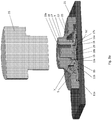
- Figs. 3a and 3b provide perspective, cross-sectional, views of the button assembly of Fig. 1 .
- fig. 3a illustrates the button assembly prior to the application of force to the actuator member i.e. a perspective, cross-sectional, view of the button assembly when in the state illustrated in Fig 2a ; in Figure 3a , for clarity, the actuator member 25 is shown removed from the interface member 7 so as to allow for a clearer view of the interface member 7.
- Fig. 3b illustrates the button assemble after force has been applied to the actuator member to cause the dome member to collapse inwardly i.e. a perspective, cross-sectional, view of the button assembly when in the state illustrated in Fig 2c .
- Fig. 4 shows a cross-sectional view of a button assembly 40 according to further embodiment of the present invention.
- the button assembly 40 has many of the same features as the button assembly 1 shown in Fig.1 and like features are awarded the same reference numbers.
- the button assembly 40 comprises the restrictor member 48 comprises a first portion 18a which extends, from the level where the elastic member 19 connects to the restrictor member 48, away from the platform 3; and second portion 18b which extends, from the level where the elastic member 19 connects to the restrictor member, towards the platform 3.
- the first portion 18a and second portion 18b may take any suitable shape such as, for example, cube-shaped, cuboid-shaped, frustoconical-shaped, a form having opposing elliptical-shaped surfaces such as a substantially cylindrical-shape having opposing elliptical-shaped surfaces.
- the surface 29 which faces towards the platform 3, can therefore any suitable shape, such as, for example square-shape, rectangular-shape, circular-shape, elliptical-shape etc.
- a surface 29 of the second portion 18b which faces towards the platform 3, is configured to be curved.
- the surface 29 which faces towards the platform 3, has a concave, flat or convex shape.
- the surface 29 which faces towards the platform 3, has a concave, shape; most preferable the surface 29 is bowl-shaped or inverted-bowl-shaped.
- the surface 29 is configured to have a radius of curvature within the range 5.0mm - 12.0mm. Most preferably the surface 29 is configured to have a radius of curvature of 10.0 mm.
- the curved surface 29 provided in the button assembly 40 will provide for a desired sound when the dome member 5 collapses inwardly.
- Fig. 5 shows a cross-sectional view of a button assembly 150 according to further embodiment of the present invention.
- the button assembly 150 has many of the same features as the button assembly 1 shown in Fig.1 and like features are awarded the same reference numbers.
- the electrical contact 151 may comprise any suitable electrically conducting material; for example electrical contact 151 may comprise any one or more or, carbon, silicone having carbon particles, metal (such as gold, copper, silver, nickel, brass), the electrical contact 151 may comprises metal blank or a substrate plated with metal such as gold, tin or nickel (e.g. 2-5um thickness) or gold (e.g. 50-200nm thickness) for example.
- the electrical contact 151 comprises a metallic disk.
- the electrical contact 151 comprises electrically conducting wires.
- the platform 3 further comprises a third and fourth electrode 155a, 155b.
- the electrical contact 151 (which is attached to the surface 29 of the second portion 18b of the restrictor member 18) overlays at least a part of each of the third and fourth electrodes 155a,155b. Accordingly, during use, the restrictor member 18 is moved towards the platform 3, so as to bring the electrical contact 151 into physical and electrical contact with the third and fourth electrodes 155a, 155b; the electrical contact 151 will therefore electrically connect the third and fourth electrodes 155a, 155b.
- the distance 'b1' (measured in a direction perpendicular to the plane of the platform 3) between the electrical contact 151 and each of the third and fourth electrodes 155a,155b is within the range 0.05mm - 0.5mm.
- the third and fourth electrodes 155a, 155b may be part of an electrical circuit (such as an electrical circuit in a automobile for opening and closing a window in the automobile) and the electrical connection between the third and fourth electrodes 155a, 155b provided by the electrical contact 151 on the restrictor member 18, may close that electrical circuit; the closing of the electrical circuit may result in a predefined actuation (such as the closing of the window of a car).
- the restrictor member 18 by applying a pressing force to the button assembly 150 the restrictor member 18 is moved towards the platform 3; the electrical contact 151 on the restrictor member 18 will moved to abut the third and fourth electrode 155a,155b so as to electrically connect the third and fourth electrode 155a, 155b; continued pressing of the button assembly will then cause the dome member 5 collapses inwardly so that the portion 15 of the dome member 5 which is adjacent the aperture 13 will move into electrical contact with the second electrode 11b so that the dome member 5 electrically connects the first and second electrode 11a, 11b.
- the electrical contact 151 on the restrictor member 18 will electrically connect the third and fourth electrodes 155a,155b and the dome member 5 will electrically connect the first and second electrodes 11a, 11b.
- the third and fourth electrodes 155a,155b may be part of a first electrical circuit and the first and second electrodes 11a, 11b may part of a second, different, electrical circuit; or in another embodiment the third and fourth electrodes 155a,155b and the first and second electrodes 11a, 11b are part of the same electrical circuit.
- FIG10 provides a cross sectional view of a button assembly 160 according to a further embodiment of the present invention.
- the button assembly 160 has many of the same features as the button assembly 1 shown in Fig.1 and like features are awarded the same reference numbers.
- the button assembly 160 further comprises damper member 161 which is attached to the surface 29 of the second portion 18b of the restrictor member 18 (it will be understood that the restrictor member 18 may have any shape; and that the damper member 161 will be attached to the surface 29 of the restrictor member 18 which is facing the platform regardless of the shape of the restrictor member 18).
- the damper member is defined simply by a block of suitable material which is attached to the surface 29 of the second portion 18b of the restrictor member 18.
- damper member 161 may take any suitable form, for example, in other embodiments the damper member 161 may be defined by one more nodules of suitable material, or layer of suitable material, or a film of suitable material, which is/are provided on the surface 29 of the restrictor member 18.
- the damper member 161 may comprise any suitable material; for example damper member 161 may comprise any one or more or, carbon, silicone having carbon particles, silicone having metal particles (such as gold, copper, silver, nickel, brass), or silicone having organic or inorganic particles (such as ceramics, silica), or any other suitable material composition.
- the distance 'b1' (measured in a direction perpendicular to the plane of the platform 3) between the damper member 161 and the platform 3 is within the range 0.05mm - 0.5mm.
- the damper member 161 will contact platform 3; due to the material composition of the damper member 161 less noise will be created upon contact of the damper member 161 with the platform 3 compared to if the surface 29 were to directly contact the platform 3; thus the button assembly 160 of Fig. 10 can achieve an even quieter operation.
- dome member 5 used in the button assembly of the present invention may take any suitable form.
- Figs. 6 and 7 provide a perspective view of two possible configurations for the dome member which could be used in any of the button assembly embodiments of the present invention.
- Fig. 6 illustrates a dome member 5 which has an aperture 13 defined therein at its centre (a rim 13a defines the aperture 13).
- the dome member 5 since the dome member 5 has an aperture defined at its centre, the dome member has a truncated-dome-shape.
- the dome member 5 has an outer rim 50.
- the dome member 5 When used in the button assembly of the present invention, typically the dome member 5 is arranged to be mounted on the first electrode 11a so that the outer rim 50 of the dome member physically and electrically contacts the first electrode 11a.
- the portion 15 of the dome member 5 which is adjacent the aperture 13 will overlay at least a portion of the second electrode 11b in the button assembly, so that the dome member 5 can be selectively collapsed inwardly by the application of force, to bring the portion 15 of the dome member which is adjacent the aperture 13 into electrical contact with the second electrode 11b.
- Fig. 7 provides a perspective view another possible configuration for the dome member 5.
- the dome member 5 comprises a dome-shaped portion 5a having an aperture 13 defined therein at its centre (a rim 13a defines the aperture 13).
- the dome member 5 further comprises a quadrilateral base portion 70 (i.e. a base which is quadrilateral shaped).
- the quadrilateral base portion 70 is planar (or substantially planar), and the dome-shaped portion 5a extends from the quadrilateral base portion 70.
- quadrilateral base portion 70 has rounded edges; more specifically in this example quadrilateral base portion 70 has a square shaped perimeter having rounded edges.
- the quadrilateral base portion 70 comprises leg members 71a-d at each of its four corners.
- the quadrilateral base portion 70 may comprise any number of leg members, and the leg members may be located at any suitable position on the quadrilateral base portion 70.
- Each of the leg members 71a-d extend in a direction opposite to the direction in which the dome-shaped portion 5a extends from the quadrilateral base portion 70.
- the dome member 5 is arranged to be mounted on the first electrode 11a so that each of the four leg members 71a-d of the dome member physically and electrically contact the first electrode 11a.
- the portion 15 of the dome member 5 which is adjacent the aperture 13 (more specifically the portion 15 of the dome member 5 which is adjacent the rim 13a which defines the aperture 13) will overlay at least a portion of the second electrode 11b in the button assembly, so that the dome-shaped portion 5a of the dome member 5 can be selectively collapsed inwardly by the application of force, to bring the portion 15 of the dome member 5 which is adjacent the aperture 13 into electrical contact with the second electrode 11b.
- the dome member 5 does not comprise any aperture 13; in such embodiments the dome member 5 make take either of the forms shown in Figs. 6 or 7 , but without the aperture 13.
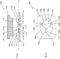
- Fig. 8a shows a cross-sectional view of the button assembly 100 according to a further embodiment which is not part of the present invention.
- Fig. 8b shows a transverse view of the button assembly 100.
- the button assembly 100 comprises, a platform 103, a dome member 105, an interface member 107 and, optionally, an actuator member 125.
- the platform 103 is preferably a printed circuit board (PCB).
- the platform is has at least a first electrode 111a and a second electrode 111b, wherein the first and second electrodes are insulated from one another.
- each of the first electrode 111a is annular shaped and the second electrode 111b is disk-shaped.
- the second electrode 111b is contained within an area defined by the annular-shaped first electrode 111a.
- the first electrode 111a and the second electrode 111b may take any suitable shape of configuration.
- the dome member 105 comprises electrically conductive material (e.g. stainless steel, copper, nickel plated, gold plated, silver plated). Unlike the previous embodiment illustrated in Fig 1 , the dome member 105 does not have an aperture defined at its centre. Accordingly in this embodiment the dome member 105 comprises an apex 115a.
- electrically conductive material e.g. stainless steel, copper, nickel plated, gold plated, silver plated.
- the dome member 105 is electrically connected to the first electrode 111a.
- dome member 105 comprises a dome shaped portion 105 having at least four arched cut-outs 106a-d, so as to define at least four leg portions 136a-d. Each of the four leg portions 136a-d are positioned so that they rest on the first electrode 111a, so that the dome member 105 physically and electrically contacts the first electrode 111a.
- the dome member 105 may take any suitable configuration. In another embodiment the dome member 105 does not comprise any arched cut-outs 106a-d. It should be understood that the dome member 105 may have any of the features of the dome member 5 used in the previously described embodiments. For example, in one embodiment the dome member 105 may optionally comprise a dome shaped portion, which does not have an aperture defined at its centre, and which is attached to a quadrilateral base portion (e.g. the quadrilateral base portion 70 shown in Figure 7 ).
- the dome member 105 is arranged so that a centre portion 115 of the dome member 105 overlays at least a portion of the second electrode 111b, so that the dome member 5 can be selectively collapsed inwardly by the application of force to bring the centre portion 115 of the dome member 105 into electrical contact with the second electrode 111b.
- the centre portion 115 is defined by the apex 115a of the dome member 105; in other words in this example the dome member 105 is arranged so that the apex 115a of the dome member 105 overlays the second electrode 111b.
- the dome member 105 electrically connects the first electrode 111a and a second electrode 111b.
- this connection will close a circuit, and will result in some predefined actuation taking place (e.g. the closing of an electrically controlled window in a car).
- the second electrode 111b is disk-shaped and the dome member 105 is arranged so that the apex 115a of the dome member 105 is aligned with the centre of the disk-shaped second electrode 111b.
- the interface member 107 comprises, a compression member 117, a restrictor member 118 and at least one elastic member 119.
- the interface member 107 is composed of material having a Young's Modulus within the range 0.9N/mm2 - 6.0N/mm2, corresponding to a hardness of between 30°ShoreA - 80°Shore A. Most preferably the interface member 107 is composed of material having a Young's Modulus of 3.0N/mm2, corresponding to a hardness of 60°ShoreA. In this example the interface member 107 is composed of silicone material; however it will be understood that the interface member 7 could be composed of any other suitable material; preferably the material is an elastomer.
- the interface member 107 is formed from a single moulded piece, thus the compression member 107, a restrictor member 118 and the at least one elastic member 119, are simply different parts of that single moulded piece.
- the interface member 107 is not limited to being a single moulded piece; the compression member 117, a restrictor member 118 and the at least one elastic member 119, could be formed from different respective pieces which are attached to one another using a suitable means of attachment.
- the compression member 117 is attached to said centre portion 115 of the dome member 105. Specifically, the compression member 117 is attached to the apex 115a of the dome member 105.
- the compression member 117 may take any suitable configuration.
- the compression member 117 comprises a block 117, having a first portion 117a and a second portion 117b.
- the first portion 117a and a second portion 117b may have any suitable shape, form or configuration.
- the first portion 117a comprises a cylindrical portion 117a and the second portion 117b comprises a fustoconical portion 117b.
- the fustoconical portion 117b of the compression member 117 is attached to said centre portion 115 of the dome member 105 i.e. the fustoconical portion 117b of the compression member 117 is attached to the apex 115a of the dome member 105.
- the circular surface 117c of the fustoconical portion 117b which has the shortest diameter, is attached to said centre portion 115 (apex 115a) of the dome member 105.
- the compression member 117 may have any suitable dimensions; in this example the cylindrical portion 117a which has a cross section having a diameter in the range 3.0mm-10.0mm and the fustoconical portion 117b which has a cross section having a a diameter in the range 3.0mm-8.0mm.
- the restrictor member 118 is arranged to project towards the platform 3.
- the distance 'b1' (measured in a direction perpendicular to the plane of the platform 3) between the platform 103 and the restrictor member 118 is less than the distance 'b2' (measured in a direction perpendicular to the plane of the platform 103) between the second electrode 111b and said centre portion 115 of the dome member 105.
- the restrictor member 118 comprises one or more surfaces 29 which face the platform 3, and the distance 'b1' (measured in a direction perpendicular to the plane of the platform 3) is the distance between the platform 103 and the surface 29 of the restrictor member 118.
- the restrictor member 118 may take any suitable configuration.
- the restrictor member 118 is defined by at least one pillar member; specifically in this example the restrictor member 118 is defined by two pillar members 118a, 118b.
- the two pillar members 118a, 118b may have any suitable dimensions; in this example each of the two pillar members 118a, 118b are cylindrical shaped; and most preferably each of the two pillar member 118a,118b have a cross section which has a cross section having a diameter of 2.0mm.
- Each of the two pillar members 118a,118b will comprise a respective surface 29a,29b which face the platform 3.
- the two pillar members 118a,118b are positioned symmetrically with respect to the dome member 105. Specifically the two pillar members 118a, 118b are positioned at opposite sides of the dome member 105. In this example, each of the two pillar members 118a, 118b are cylindrical shaped. Accordingly the respective surfaces 29a,29b of the two pillar members 118a, 118b will each be circular shaped. However it will be understood that the two pillar members 118a, 118b make take any suitable shape or configuration.
- each of the two pillar members may be cube-shaped, cuboid-shaped, frustoconical-shaped; may be a form having opposing elliptical-shaped surfaces such as a substantially cylindrical-shape having opposing elliptical-shaped surfaces.
- the shape of the pillar members 118a,118b will determine the shape 29 of the surface 29a,29b.
- the two pillar members 118a, 118b may each be cube-shaped resulting in the surfaces 29a29b each being square shaped; the two pillar members 118a, 118b may each be cuboid-shaped resulting in the surfaces 29a29b each being rectangular or square shaped; the two pillar members 118a, 118b may each be frustoconical-shaped resulting in the surfaces 29a29b each being circular shaped; in yet another example the two pillar members 118a, 118b may each be in a form having opposing elliptical-shaped surfaces resulting in the surfaces 29a29b each being elliptical shaped, for example the two pillar members 118a, 118b may each be substantially cylindrical-shape having opposing elliptical-shaped surfaces, resulting in the surfaces 29a29b each being elliptical shaped.
- the shape of the surfaces 29a,29b will influence the sound made when the dome member 105 collapses inwardly.
- the restrictor member 118 may comprise any number of pillar members. Most preferably the pillar members will be arranged symmetrically with respect to one another. So, for example, it the restrictor member 118 comprises three pillar members then the three pillar members will be positioned 120° apart; if the restrictor member 118 comprises four pillar members then the four pillar members will be positioned 90° apart. In yet a further embodiment the restrictor member 118 comprises and annular member which is arranged around the compression member 117.
- the interface member 117 comprises at least one elastic member 119.
- interface member 117 comprises a two elastic members, a first elastic member 119a and a second elastic member 119b.
- the elastic member 119 connects the restrictor member 118 to the compression member 117; specifically in this example the first elastic member 119a connects the one pillar member 118a to the compression member 117 and the second elastic member 119b connects the other pillar member 118b to the compression member 117.
- the first elastic member 119a is interposed between one pillar member 118a and the compression member 117
- the second elastic member 119b is interposed between the other pillar member 118b and the compression member 117. Since each of the first and second elastic members 119a,119b are elastic, they can each stretch to allow compression member 117 to be moved with respect to the respective pillar members 118a,118b.
- the first and second elastic members 119a,b each preferably has a thickness "a" (measured in a direction perpendicular to the plane of the platform 3) within the range 0.15mm-0.8mm. Most preferably each of the first and second elastic members 119a,b has a thickness "a” (measured in a direction perpendicular to the plane of the platform 3 of 0.4mm.
- the interface member 107 further comprise an anchoring portion 121.
- the anchoring portion 121 is fixed, directly or indirectly, to the platform 103.
- the anchoring portion 121 is fixed to first electrode 111a on the platform 103, so that anchoring portion 121 is fixed indirectly to the platform 103.
- the interface member 117 comprises a wall member 135 which is arranged to surround the first portion 117a of the compression member 117.
- a flexible member 123 connects the anchoring portion 121 to the wall member 135.
- a channel 137 is defined between the wall member 135 and the first portion 117a of the compression member 117.
- Each of the first and second pillar members 118a,118b are located opposite to, and are aligned with, the channel 137; and each of the first and second pillar members 118a,118b project in a direction away from the channel 137 towards the platform 103.
- the anchoring portion 121 may take any suitable shaped, for example the anchoring portion 21 may be annular shaped, oval shaped, square shaped, rectangular shaped, square shaped with rounded edges, or rectangular shaped with rounded edges. In this example, as can be seen from Fig 8b , the anchoring portion 121 is rectangular shaped with rounded edge.
- the button assembly 100 further comprises an actuator member 125 which is mounted on the interface member 107.
- the actuator member 125 is configured to be attached to, or to abut, both the compression member 117 and the restrictor member 118.
- the button assembly 100 operates in a similar fashion to the button assembly 100 of Fig 1 .
- Fig. 9a shows a cross-sectional view of the button assembly 400 according to a further embodiment which is not part of the present invention.
- Fig. 9b shows a transverse view of the button assembly 400.
- the button assembly 400 has many of the same features as the button assembly 100 shown in Figs. 8a and 8b and like features are awarded the same reference numbers. However the button assembly 400 comprises a compression member 417 which comprises a single pillar member 417a only.
- single pillar member 417a is cylindrical shaped. Accordingly the surface 29 of the single pillar member 417 which is facing the platform 103 will be circular shaped. However it will be understood that the single pillar member 417a make take any suitable shape or configuration.
- the single pillar member 417a may be cube-shaped, cuboid-shaped, frustoconical-shaped; may be a form having opposing elliptical-shaped surfaces such as a substantially cylindrical-shape having opposing elliptical-shaped surfaces.
- the shape of the single pillar member 417a will dictate the shape of the surface 29 which faces the platform 103.
- the interface member 117 comprises a single elastic member 119a.
- the single elastic member 119a connects the single pillar member 417a to the compression member 117.
- the single elastic member 119a is interposed between the single pillar member 417a and the compression member 117. Since each of the single elastic member 119a is elastic, it can each stretch to allow compression member 117 to be moved with respect to the single elastic member 119a.
- the single elastic member 119a preferably has a thickness "a" (measured in a direction perpendicular to the plane of the platform 3) within the range of 0.15mm-0.8mm. Most preferably the single elastic member 119a has a thickness "a" (measured in a direction perpendicular to the plane of the platform 3) of 0.4mm.
- the interface member 107 comprises an anchoring portion 121.
- the anchoring portion 121 is fixed to the platform 103.
- the interface member 417 comprises a wall member 435 and a channel 437 is defined between the wall member 435 and the cylindrical portion 117a of the compression member 117.
- the single pillar member 417 is located opposite to, and are aligned with, the channel 437; and single pillar member 417 projects away from the channel 437 towards the platform 103.
- a flexible member 423 connects the anchoring portion 121 to the wall member 435 and connects the anchoring portion 121 to the compression member 117.
- the button assembly 400 operates in a similar fashion to the button assembly 100 of Fig 1 .
Landscapes
- Push-Button Switches (AREA)
- Mechanisms For Operating Contacts (AREA)
Description
- The present invention concerns button assembly, and in particular a button assembly which uses an elastic member to slow the speed at which a metal dome collapses inwardly upon the application of force, thereby reducing the noise which the elastic member makes when it is collapsed inwardly.
- Existing button assemblies typically comprise a dome member composed of electrically conductive material. This dome member is arranged to be electrically connected to a first electrode (typically the dome member will be mounted on the first electrode so that the base of the dome member will be in physical and electrical contact with the first electrode). The centre region of the dome is typically aligned over a second electrode. As a result, when a pressing force is applied to the dome member to cause the dome member to collapse inwardly, the centre region of the dome will come into contact with the second electrode; in its collapsed state the dome member will electrically connect the first and second electrodes. Disadvantageously, when the pressing force is applied to the dome member the dome will tend to collapse inwardly under a fast snapping action; this fast, snapping, collapse inward motion generates a undesirable loud noise.
-
JP2002025386 -
JP2003308758 - JPH03214521 discloses achieving a metallic, crisp and clicking feeling by moving both of a movable point and a tactile plate almost at the same time to change over a circuit configuration of two circuits and one contact. When a presser is pressed, a tactile plate is pressed down and at the same time a movable contact member is also moved downward, and the tactile plate, when continuously pressed down, is turned over and moved into contact with the second fixed contact. The contact causes a set of terminals to be closed to form one circuit, and at the same time two contact of the contact portions of the movable contact member with the first fixed contact pair causes other set of terminals to be closed to form another circuit. In this way, a circuit configuration of two circuits and one contact is realized to bring a metallic, crisp and clicking feeling.
- It is an aim of the present invention to mitigate or obviate at least some of the disadvantages associated with existing button assemblies.
- According to the invention, these aims are achieved by means of a button assembly, comprising, a platform having at least two electrodes; a dome member which comprises electrically conductive material, wherein the dome member is electrically connected to at least one of said at least two electrodes, and the dome is arranged so that at least a portion of the dome member overlays at least one other of the at least two electrodes, so that when the dome member is selectively collapsed inwardly by the application of force, the dome member will electrically contact said at least one other of the at least two electrodes, so that in its collapse state the dome member electrically connects the at least one of said at least two electrodes with the at least one other of the at least two electrodes; an interface member which comprises, (a) a compression member which is attached to the dome member at a position which overlays said at least one other of the at least two electrodes; (b) a restrictor member which is configured such that it projects towards the platform and the distance between the platform and the restrictor member is less than the distance between said at least one other of the at least two electrodes and portion of the dome which overlays at least one other of the at least two electrodes, and (c) at least one elastic member which connects the restrictor member and the compression member ,wherein the restrictor member comprises a surface which faces the platform, the distance being the distance between the platform and the surface, wherein, upon application of a pressing force to the button assembly, the restrictor member abuts the platform before the portion of the dome members which overlays the second electrode is moved by the compression members to a position where it contacts the second electrode, wherein that the dome member has an aperture defined therein and wherein the restrictor member comprises a block which extends through the aperture towards the platform.
- Preferably the platform is a printed circuit board (PCB).
- The second electrode may be annular shaped.
- The block may comprise a surface which faces the platform, and wherein said surface has a circular-shaped perimeter, a square-shaped perimeter, a rectangular-shaped perimeter, or an elliptical- shaped perimeter.
- In an embodiment said surface has a circular-shaped perimeter, and the diameter of the circular-shaped perimeter is between 0.6mm-3.0mm.
- The surface may be concave, or convex, or flat.
- In an embodiment an electrical contact may be attached said surface.
- In an embodiment a damper member is attached said surface.
- The compression member may comprise two or more nodules which are located symmetrically with respect to one another; and wherein said two or more nodules are each attached to the portion of the dome member which overlays said at least one other of the at least two electrodes. Preferably the two or more nodules are each attached to the portion of the dome member which is adjacent a rim which defines said aperture at the centre of the dome member.
- The compression member may comprise an annular rim. The annular rim is preferably attached to the portion of the dome member which overlays said at least one other of the at least two electrodes.
- The dome member may comprise a quadrilateral base portion
- In one preferred embodiment the a button assembly, comprises, a platform having at least a first electrode and a second electrode, wherein the first and second electrodes are insulated from one another; an dome member which comprises electrically conductive material, wherein the dome member has an aperture defined therein at its centre, wherein the dome member is electrically connected to the first electrode, and a portion of the dome member which is adjacent the aperture overlays at least a portion of the second electrode, so that the dome member can be selectively collapsed inwardly by the application of force to bring the portion of the dome member which is adjacent the aperture into electrical contact with the second electrode, so that in its collapse state the dome member electrically connects the first electrode and a second electrode; an interface member which comprises, a compressor member which is attached to said portion of the dome member which is adjacent the aperture, a restrictor member which is arranged to project through said aperture in the dome member towards the platform, and wherein the distance between the platform and the restrictor member is less than the distance between the second electrode and said portion of the dome member which is adjacent the aperture, and at least one elastic member which connects the restrictor member and the compressor member.
- In an embodiment, the dome member has an aperture defined therein at its centre, so the dome member has a truncated-dome shape.
- In an embodiment the dome member comprises a dome shaped portion having at least four arched cut-outs, so as to define at least four leg portions, wherein each of the at least four leg portions are arranged to be electrically connected to the first electrode .
- The at least one elastic member preferably has a thickness "a" (measured in a direction perpendicular to the plane of the platform 3) within the range 0.15mm-0.8mm.
- Preferably the restrictor member is arranged so that the distance 'b' between the restrictor member and the platform (measured in a direction perpendicular to the plane of the platform 3) is less than 3mm. Most preferably the restrictor member is arranged so that the distance 'b' (measured in a direction perpendicular to the plane of the platform 3) between a surface the restrictor member which faces the platform, and the platform, is less than 3mm.
- Preferably the interface member is composed of a material having a hardness of between 40 shore A- 70 shore A.
- In an embodiment the first electrode may have an annular shape. In an embodiment the second electrode may have annual shape.
- The compressor member may comprise one or more nodules. Each of the one or more nodules are attached to the dome member. Most preferably each of the one or more nodules are attached to the portion of the dome member which overlays the second electrode. Preferably the compressor member comprises at least two nodules. The at least two nodules are positioned symmetrically with respect to one another. The compressor member may comprise an annular member and the at least two nodules may be located systemically on said annular member.
- The compressor member may comprise an annular member which comprises an annular rim which is attached to the dome member. Most preferably compressor member may comprise an annular member which comprises an annular rim which is attached to the portion of the dome member which overlays the second electrode.
- The restrictor member may comprise a block member. The block member preferably comprises a first portion and a second portion. The block member may be configured to have an inverted T-shaped cross section.
- The interface member may further comprises an anchoring portion, and wherein a flexible member connects the anchoring portion to the compressor member. Preferably the anchoring portion is fixed to the platform.
- Preferably assembly further comprises a actuator member which is mounted on the interface member. The actuator member is attached to, or abuts, the compressor member. In one embodiment there is a gap between the restrictor member and the actuator member. In another embodiment the there is no gap between the restrictor member and the actuator member; in other words in another embodiment the actuator member is attached to, or abuts, the restrictor member.
- In an embodiment the dome member comprises a dome shaped portion and quadrilateral base portion, wherein the dome shaped portion is attached to and extends from the quadrilateral base portion . In one embodiment the dome shaped portion has an aperture defined at its centre; in another embodiment the dome shaped portion comprises an apex. Preferably the dome member is arranged so that the quadrilateral base portion is mounted on the first electrode so that the quadrilateral base portion is physically and electrically connected to the first electrode.
- In an embodiment the first electrode has an annular shape, and the second electrode is contained within an area defined by the annular shape of the first electrode.
- The invention will be better understood with the aid of the description of embodiments given by way of example only, and illustrated by the figures, in which:
-
Fig. 1 shows a cross-sectional view of a button assembly according to one embodiment of the present invention; -
Figs. 2a-c show the various states of the button assembly when a pressing force is applied to the button assembly; -
Figs. 3a and3b provide perspective, cross-sectional, views of the button assembly ofFig. 1 ;Fig. 3a illustrates the button assembly prior to the application of force to the actuator member, andFig. 3b illustrates the button assemble after force has been applied to the actuator member to cause the dome member to collapse inwardly; -
Fig. 4 shows a cross-sectional view of a button assembly according to further embodiment of the present invention; -
Fig. 5 shows a cross-sectional view of a button assembly according to further embodiment of the present invention; -
Figs. 6 and7 provide perspective views of two possible configurations for the dome member which could be used in any of the button assembly embodiment; -
Fig. 8a shows a cross-sectional view of the button assembly according to an embodiment which is not part of the present invention;Fig. 8b shows a transverse view of the button assembly ofFig. 8a taken along line A-A' ofFig. 8a ; -
Fig.9 shows a cross-sectional view of the button assembly according to a further embodiment which is not part of the present invention;Fig. 9b shows a transverse view of the button assembly ofFig. 9a taken along line A-A' ofFig. 9a ; -
Fig. 10 shows a cross-sectional view of a button assembly according to further embodiment of the present invention. - In general the present invention relates to a button assembly, comprising: a platform having at least at least two electrodes; a dome member which comprises electrically conductive material, wherein the dome member is electrically connected to at least one of said at least two electrodes, and the dome is arranged so that at least a portion of the dome overlays at least at least a portion of one other of the at least two electrodes, so that when the dome member is selectively collapsed inwardly by the application of force, the dome member will electrically contact said at least one other of the at least two electrodes, so that in its collapse state the dome member electrically connects the at least one of said at least two electrodes with the at least one other of the at least two electrodes; and an interface member comprising, a compression member which is attached to the dome member at the portion which overlays said at least one other of the at least two electrodes or at least is attached proximate to or adjacent said portion, a restrictor member which is configured such that it projects towards the platform and the distance between the platform and the restrictor member is less than the distance between said at least one other of the at least two electrodes and said portion of the dome which overlays said at least one other of the at least two electrodes; and at least one elastic member which connects the restrictor member and the compression member. As will be described various implementations of the button assembly of the present invention are possible without departing from the scope of the invention:
-
Fig. 1 shows a cross-sectional view of a button assembly 1 according to one embodiment of the present invention. - A button assembly, comprises, a
platform 3, adome member 5, aninterface member 7 and, optionally, an actuator member 9. - The
platform 3 is preferably a printed circuit board (PCB). The platform is has at least afirst electrode 11a and asecond electrode 11b, wherein the first and second electrodes are insulated from one another. In this example each of thefirst electrode 11a and thesecond electrode 11b are annular shaped. However it should be understood that thefirst electrode 11a and thesecond electrode 11b may take any suitable shape of configuration. - The
dome member 5 comprises electrically conductive material (e.g. stainless steel, copper, nickel, gold, nickel plated, and/or gold plated). Thedome member 5 has anaperture 13 defined therein at its centre. In this embodiment since thedome member 5 has an aperture defined at its centre, the dome member has a truncated-dome-shape. In another embodiment, which will be described later, the dome member is configured to be dome-shaped. In one embodiment thedome member 5 comprises a truncated-dome-shaped portion which is attached to a quadrilateral base portion (i.e. a base which is quadrilateral shaped); in such an embodiment it is preferable that quadrilateral base portion is arranged to be electrically connected to thefirst electrode 11a; for example thedome member 5 could be arranged so that the quadrilateral base portion is mounted on thefirst electrode 11a so that thedome member 5 is physically and electrically contacts thefirst electrode 11a. - The
dome member 5 is electrically connected to thefirst electrode 11a, and aportion 15 of thedome member 5 which is adjacent the aperture 13 (more specifically theportion 15 of thedome member 5 which is adjacent arim 13a which defines the aperture 13) overlays at least a portion of thesecond electrode 11b, so that thedome member 5 can be selectively collapsed inwardly by the application of force to bring theportion 15 of the dome member which is adjacent theaperture 13 into electrical contact with thesecond electrode 11b. Accordingly, in its collapse state thedome member 5 electrically connects thefirst electrode 11a and asecond electrode 11b. Most preferably when thedome member 5 electrically connects thefirst electrode 11a and asecond electrode 11b this connection will close a circuit, and will result in some predefined actuation taking place. The button assembly 1 of the present invention will typically be used in an automotive application. Accordingly, in such an application, when thedome member 5 electrically connects thefirst electrode 11a and asecond electrode 11b this connection will close a circuit, and will result in some predefined actuation taking place in the automobile, such as, the closing of an electrically controlled window in the automobile for example. - The
interface member 7 comprises, acompression member 17, arestrictor member 18 and at least oneelastic member 19. - The
interface member 7 is composed of material having a Young's Modulus within the range 0.9 N/mm2 - 6.0 N/mm2, which is equivalent to a measured hardness of between 30° ShoreA - 80°ShoreA. Most preferably theinterface member 7 is composed of material having a hardness of 2.0 N/mm2 which is equivalent to a measuredhardness 50° ShoreA. Most preferably theinterface member 7 is composed of material having a hardness related to the required function. In this example theinterface member 7 is composed of silicone material; however it will be understood that theinterface member 7 could be composed of any other suitable elastomeric material. Theinterface member 7 may comprise, for example, silicon, fluorosilicone, Ethylene propylene diene monomer (EPDM), natural rubber, and/or a thermoplastic elastomer (TPE). In the example theinterface member 7 is formed from a single moulded piece, thus thecompression member 17, arestrictor member 18 and the at least oneelastic member 19, are simply different parts of that single moulded piece. However, it should be understood that theinterface member 7 is not limited to being a single moulded piece; thecompression member 17,restrictor member 18 and the at least oneelastic member 19, could be formed from different respective parts which are attached to one another using a suitable means of attachment. - The
compression member 17 is attached to saidportion 15 of thedome member 5 which is adjacent theaperture 13. - In this example the
compression member 17 comprises anannular member 57 which comprises anannular rim 17a which is attached to theportion 15 of thedome member 5 which is adjacent theaperture 13; thus the annular rim will be attached to theportion 15 of thedome member 5 around the whole circumference of theaperture 13. Thus in this other embodiment, the shape of theannular rim 17a corresponds to the shape of thesecond electrode 11b i.e. bothsecond electrode 11b and theannular rim 17a may be annular shaped. - It will be understood that the
compression member 17 may take any suitable configuration. In yet another example thecompression member 17 comprises one or more nodules. Importantly, the one or more nodules are attached to theportion 15 of thedome member 5 which is adjacent theaperture 13. In embodiments in which thecompression member 17 comprises two or more nodules, preferably the two or more nodules are located symmetrically on the annular member 57.Preferably in embodiments in which thecompression member 17 comprises two or more nodules, then the nodules are located symmetrically with respect to one another. For example if there are three nodules provided then the three nodules will be located 120° apart from one another; if there are four nodules provided then the four nodules will be located 90° apart from one another. Most preferably thecompression member 17 comprises theannular member 57 and the nodules are located symmetrically on saidannular member 57. In yet a further embodiment thecompression member 17 may comprise a single nodule only on theannular member 57 - The
restrictor member 18 is configured to project through saidaperture 13 in thedome member 5, towards theplatform 3. The distance 'b1' (measured in a direction perpendicular to the plane of the platform 3) between theplatform 3 and therestrictor member 18 is less than the distance 'b2' (measured in a direction perpendicular to the plane of the platform 3) between thesecond electrode 11b and saidportion 15 of thedome member 5 which is adjacent theaperture 13. Preferably therestrictor member 18 is arranged such that the distance 'b1' (measured in a direction perpendicular to the plane of the platform 3) between theplatform 3 and therestrictor member 18 is less than 0.5mm. Most preferably therestrictor member 18 is arranged such that the distance 'b1' is 0.15mm. Preferably thedome member 5 is configured such that the distance 'b2' (measured in a direction perpendicular to the plane of the platform 3) between thesecond electrode 11b and saidportion 15 of thedome member 5 which is adjacent theaperture 13 is within the range 0 - 1.0mm. Most preferably thedome member 5 is configured such that the distance 'b2' is 0.3mm. - Most preferably the
restrictor member 18 is arranged such that the distance 'b1' (measured in a direction perpendicular to the plane of the platform 3) between theplatform 3 and therestrictor member 18 is within the range 0.05mm - 0.5mm; and thedome member 5 is configured such that the distance 'b2' (measured in a direction perpendicular to the plane of the platform 3) between thesecond electrode 11b and saidportion 15 of thedome member 5 which is adjacent theaperture 13 is within the range 0.1 mm-0.5mm. - It will be understood that the
restrictor member 18 may take any suitable configuration. In this example therestrictor member 18 comprises ablock member 18 having afirst portion 18a and asecond portion 18b. Thefirst portion 18a comprises a firstcylindrical portion 18a which extends, from the level where theelastic member 19 connects to the restrictor member, away from theplatform 3; and thesecond portion 18b comprises a secondcylindrical portion 18b which extends, from the level where theelastic member 19 connects to the restrictor member, towards theplatform 3. The diameter of the secondcylindrical portion 18b is larger than the diameter of the firstcylindrical portion 18a; accordingly in this embodiment therestrictor member 18 has cross section which has an inverted T-shape. Preferably the diameter of the secondcylindrical portion 18b is within the range 0.6mm-3.0mm. Preferably the diameter of the firstcylindrical portion 18a is between 1.0mm - 3.5mm. Most preferably the diameter of the secondcylindrical portion 18b is 2.0mm and the diameter of the firstcylindrical portion 18a is 1.5mm It should be understood that the present invention is not limited to requiring therestrictor member 18 to comprise ablock member 18 having a firstcylindrical portion 18a and secondcylindrical portion 18b. - The
second portion 18b comprises asurface 29 which faces theplatform 3. It should be understood that in the present application, most preferably, the distance 'b1' (measured in a direction perpendicular to the plane of the platform 3) is the distance between theplatform 3 and thesurface 29 of therestrictor member 18 which is facing theplatform 3. - The shape of the
surface 29 will influence the sound made when thedome member 5 collapses inwardly to bring theportion 15 of the dome member which is adjacent theaperture 13 into electrical contact with thesecond electrode 11b. Different shapes of thesurface 29 will provide different sounds when thedome member 5 collapses inwardly. In this example thesecond portion 18b is defined by the secondcylindrical portion 18b thesurface 29 will have a circular shape (most preferably the surface has a circular-shaped perimeter, and the diameter of the circular-shaped perimeter is within the range 0.6mm-3.0mm). However it will be understood that thesecond portion 18b may be provided with any suitable shape so as to achieve any suitable shape for thesurface 29. Accordingly, thesecond portion 18b may take any suitable shape or form: for example thesecond portion 18b may be cube-shaped resulting in thesurface 29 being square shaped (i.e. the perimeter of thesurface 29 being square shaped); thesecond portion 18b may be cuboid-shaped resulting in thesurface 29 being rectangular or square shaped (i.e. the perimeter of thesurface 29 being rectangular or square shaped); thesecond portion 18b may be frustoconical -shaped or cylindrical-shaped, resulting in thesurface 29 being circular shaped (i.e. the perimeter of thesurface 29 being circular shaped); in yet another example thesecond portion 18b may be in a form having opposing elliptical-shaped surfaces resulting in thesurface 29 being elliptical shaped (i.e. the perimeter of thesurface 29 being elliptical shaped), for example thesecond portion 18b may be substantially cylindrical-shape having opposing elliptical-shaped surfaces, resulting in thesurface 29 being elliptical shaped. Likewise it should be understood that thefirst portion 18a may take any suitable shape or form; for example thefirst portion 18a may be cube-shaped, cuboid-shaped, frustoconical-shaped; may be a form having opposing elliptical-shaped surfaces such as a substantially cylindrical-shape having opposing elliptical-shaped surfaces. - As mentioned the
interface member 7 comprises at least oneelastic member 19. In thisexample interface member 7 comprises a single annular-shapedelastic member 19. Theelastic member 19 connects therestrictor member 18 and thecompression member 17. Thus theelastic member 19 is interposed between therestrictor member 18 and thecompression member 17. Specifically, in this example theelastic member 19 connects to therestrictor member 18 adjacent the interface between the firstcylindrical portion 18a and secondcylindrical portion 18b; theelastic member 19 connects to theannular member 57 of thecompression member 17, at a position which is above the plane on which the twonodules 17a,17b lay. - Since the
elastic member 19 is elastic, it can stretch to allow therestrictor member 18 and thecompression member 17 to be moved with respect to one another. - The
elastic member 19 preferably has a thickness "a" (measured in a direction perpendicular to the plane of the platform 3) within the range 0.15mm-0.8mm. Most preferablyelastic member 19 has a thickness "a" (measured in a direction perpendicular to the plane of the platform 3) of 0.4mm. - The
interface member 7 is shown to further comprise an anchoringportion 21. The anchoringportion 21 is fixed, directly or indirectly, to theplatform 3. Specifically, in this example the anchoringportion 21 is fixed tofirst electrode 11a on theplatform 3, so that anchoringportion 21 is fixed indirectly to theplatform 3. Aflexible member 23 connects the anchoringportion 21 to thecompression member 17. Theflexible member 23 is configured so as to allow thecompression member 17 to be moved with respect to the anchoringportion 21; specifically when a pressing force is applied to thecompression member 17 the anchoringportion 21 will remain fixed, andflexible member 23 will deform (elastically) to allow the compression member to move towards theplatform 3. The anchoringportion 21 may take any suitable shape, for example the anchoringportion 21 may be annular shaped, oval shaped, square shaped, rectangular shaped, square shaped with rounded edges, or rectangular shaped with rounded edges. In this example the anchoringportion 21 is annular shaped. Likewise, theflexible member 23 may take any suitable shape; most preferably theflexible member 23 will have a shape corresponding to the anchoring member and/orcompression member 17. In this example theflexible member 23 is annular shaped. - The button assembly further comprises an
actuator member 25 which is mounted on theinterface member 7 such that it abuts theinterface member 7. It should be understood that theactuator member 25 is an optional feature of the present invention. Furthermore, if anactuator member 25 is provided, then it should be understood that it is not essential for theactuator member 25 to be mounted on theinterface member 7 such that it abuts theinterface member 7, all that is required is that theactuator member 25 can be brought into abutment with the interface member 7 (more specifically all that is required is that theactuator member 25 can be brought into abutment with thecompression member 17 of the interface member 7): in another embodiment theactuator member 25 may be positioned above theinterface member 7 so that there is a space between theactuator member 25 and theinterface member 7, and theactuator member 25 may be selectively pressed to move theactuator member 25 across the space to bring it into abutment with the interface member 7 (more specifically to bring it into abutment with thecompression member 17 of the interface member 7). - In this example the
actuator member 25 is configured to be attached to, or to abut, thecompression member 17; the restrictor member is arranged such that there is agap 27 between therestrictor member 18 and theactuator member 25. In another embodiment therestrictor member 18 is arranged such that therestrictor member 18 is also attached to, or abuts, theactuator member 25; in other words in this other embodiment there is nogap 27 between therestrictor member 18 and theactuator member 25. -
Figs. 2a-c show the various states of the button assembly 1 ofFig. 1 when in use. SpecificallyFig. 2a illustrates the state of the button assembly 1 before a pressing force is applied to the button assembly 1.Fig. 2b illustrates the state of the button assembly 1 when a pressing force is applied to the button assembly 1.Fig. 2c illustrates the state of the button assembly 1 after, when in the state illustrated inFig. 2b , continued pressing force is applied to the button assembly 1. - Referring to
Fig. 2a , no pressing force is applied to the button assembly 1. Accordingly thedome member 5 is in an uncollapsed state (i.e. is not collapsed inwardly), and theportion 15 of the dome member which is adjacent theaperture 13 is removed from thesecond electrode 11b (i.e. does not touch thesecond electrode 11b). - Referring to
Fig. 2b , a pressing force is applied to the button assembly 1. Specifically a pressing force is applied to theactuator member 25; as theactuator member 25 is pressed it will begin to move in the direction towards theplatform 3 and will also force thecompression member 17 to move towards theplatform 3. Thecompression member 17 in turn will push theportion 15 of thedome member 5 which is adjacent theaperture 13 towards thesecond electrode 11b. - Additionally, the
actuator member 25 move across thegap 27 so that theactuator member 25 is moved towards therestrictor member 18. After theactuator member 25 has been moved across thegap 27 theactuator member 25 will abut therestrictor member 18. Continued application of the pressing force, after theactuator member 25 has abut therestrictor member 18, will now move both thecompression member 17 and therestrictor member 18 in the direction of theplatform 3. - Since the distance 'b1' (measured in a direction perpendicular to the plane of the platform 3) between the
platform 3 and therestrictor member 18 is less than the distance 'b2' (measured in a direction perpendicular to the plane of the platform 3) between thesecond electrode 11b and saidportion 15 of thedome member 5 which is adjacent theaperture 13, therestrictor member 18 will abut theplatform 3 before theportion 15 of thedome member 5 which is adjacent theaperture 13 is moved by thecompression member 17 to a position where it contacts thesecond electrode 11b. When therestrictor member 18 abuts theplatform 3, further movement of therestrictor member 18 will be blocked by theplatform 3. Consequently, as the pressing force is continued to be applied, thecompression member 17 will continue to move towards theplatform 3 pushing theportion 15 of thedome member 5 which is adjacent theaperture 13 towards thesecond electrode 11b; since further movement of therestrictor member 18 is blocked by theplatform 3 thecompression member 17 will move relative to therestrictor member 18, towards theplatform 3, thereby stretching theelastic member 19. Additionally, as the pressing force is continued to be applied, therestrictor member 18 will be compressed. - Continued application of the pressing force will cause further stretching the
elastic member 19 and will cause thecompression member 17 to eventually push theportion 15 of thedome member 5 which is adjacent theaperture 13 towards thesecond electrode 11b a sufficient amount to cause thedome member 5 to collapse inwardly. It should be noted the continued application of force may also cause further compression of therestrictor member 18.Fig. 2c illustrates the button assembly 1 after thedome member 5 has collapsed inwardly. When thedome member 5 collapses inwardly theportion 15 of thedome member 5 which is adjacent theaperture 13 will move into electrical contact with thesecond electrode 11b. However, importantly, the stretchedelastic member 19 will provide an elastic force in a direction which is opposite to the direction of the inward collapse of thedome member 5; since theportion 15 of thedome member 5 which is adjacent theaperture 13 is attached to thecompression member 17, the elastic force of the stretchedelastic member 19 is transmitted to thedome member 5; consequently the speed at which thedome member 5 collapses inwardly will be slowed by the elastic force of the stretchedelastic member 19 which acts in the opposing direction. Since the speed at which thedome member 15 collapses inwardly is slowed, the noise generated by the button assembly 1 is less than those button assemblies of the prior art; in other words the button assembly of the present invention can provide a quieter operation. - Additionally, the
compressed restrictor member 18 will also provide an expansion force in a direction which is opposite to the direction of the inward collapse of thedome member 5; thus the speed at which thedome member 15 collapses inwardly is slowed even further by the expansion force which results from the compression of therestrictor member 18 against theplatform 3. -
Figs. 3a and3b provide perspective, cross-sectional, views of the button assembly ofFig. 1 . Specifically,fig. 3a illustrates the button assembly prior to the application of force to the actuator member i.e. a perspective, cross-sectional, view of the button assembly when in the state illustrated inFig 2a ; inFigure 3a , for clarity, theactuator member 25 is shown removed from theinterface member 7 so as to allow for a clearer view of theinterface member 7.Fig. 3b illustrates the button assemble after force has been applied to the actuator member to cause the dome member to collapse inwardly i.e. a perspective, cross-sectional, view of the button assembly when in the state illustrated inFig 2c . -
Fig. 4 shows a cross-sectional view of abutton assembly 40 according to further embodiment of the present invention. Thebutton assembly 40 has many of the same features as the button assembly 1 shown inFig.1 and like features are awarded the same reference numbers. - The
button assembly 40 comprises therestrictor member 48 comprises afirst portion 18a which extends, from the level where theelastic member 19 connects to therestrictor member 48, away from theplatform 3; andsecond portion 18b which extends, from the level where theelastic member 19 connects to the restrictor member, towards theplatform 3. As already described above, thefirst portion 18a andsecond portion 18b may take any suitable shape such as, for example, cube-shaped, cuboid-shaped, frustoconical-shaped, a form having opposing elliptical-shaped surfaces such as a substantially cylindrical-shape having opposing elliptical-shaped surfaces. Thesurface 29 which faces towards theplatform 3, can therefore any suitable shape, such as, for example square-shape, rectangular-shape, circular-shape, elliptical-shape etc. - Importantly, in the
button assembly 40, asurface 29 of thesecond portion 18b which faces towards theplatform 3, is configured to be curved. Specifically, thesurface 29 which faces towards theplatform 3, has a concave, flat or convex shape. In this example thesurface 29 which faces towards theplatform 3, has a concave, shape; most preferable thesurface 29 is bowl-shaped or inverted-bowl-shaped. Preferably thesurface 29 is configured to have a radius of curvature within the range 5.0mm - 12.0mm. Most preferably thesurface 29 is configured to have a radius of curvature of 10.0 mm. - Advantageously, the
curved surface 29 provided in thebutton assembly 40, will provide for a desired sound when thedome member 5 collapses inwardly. -
Fig. 5 shows a cross-sectional view of abutton assembly 150 according to further embodiment of the present invention. Thebutton assembly 150 has many of the same features as the button assembly 1 shown inFig.1 and like features are awarded the same reference numbers. - In the
button assembly 150 an electrical contact 151 is attached to thesurface 29 of thesecond portion 18b of therestrictor member 18. The electrical contact 151 may comprise any suitable electrically conducting material; for example electrical contact 151 may comprise any one or more or, carbon, silicone having carbon particles, metal (such as gold, copper, silver, nickel, brass), the electrical contact 151 may comprises metal blank or a substrate plated with metal such as gold, tin or nickel (e.g. 2-5um thickness) or gold (e.g. 50-200nm thickness) for example. In one embodiment the electrical contact 151 comprises a metallic disk. In another embodiment the electrical contact 151 comprises electrically conducting wires. - In the
button assembly 150 theplatform 3 further comprises a third andfourth electrode 155a, 155b. The electrical contact 151 (which is attached to thesurface 29 of thesecond portion 18b of the restrictor member 18) overlays at least a part of each of the third andfourth electrodes 155a,155b. Accordingly, during use, therestrictor member 18 is moved towards theplatform 3, so as to bring the electrical contact 151 into physical and electrical contact with the third andfourth electrodes 155a, 155b; the electrical contact 151 will therefore electrically connect the third andfourth electrodes 155a, 155b. Preferably the distance 'b1' (measured in a direction perpendicular to the plane of the platform 3) between the electrical contact 151 and each of the third andfourth electrodes 155a,155b is within the range 0.05mm - 0.5mm. The third andfourth electrodes 155a, 155b may be part of an electrical circuit (such as an electrical circuit in a automobile for opening and closing a window in the automobile) and the electrical connection between the third andfourth electrodes 155a, 155b provided by the electrical contact 151 on therestrictor member 18, may close that electrical circuit; the closing of the electrical circuit may result in a predefined actuation (such as the closing of the window of a car). Thus in thebutton assembly 150, by applying a pressing force to thebutton assembly 150 therestrictor member 18 is moved towards theplatform 3; the electrical contact 151 on therestrictor member 18 will moved to abut the third andfourth electrode 155a,155b so as to electrically connect the third andfourth electrode 155a, 155b; continued pressing of the button assembly will then cause thedome member 5 collapses inwardly so that theportion 15 of thedome member 5 which is adjacent theaperture 13 will move into electrical contact with thesecond electrode 11b so that thedome member 5 electrically connects the first andsecond electrode restrictor member 18 will electrically connect the third andfourth electrodes 155a,155b and thedome member 5 will electrically connect the first andsecond electrodes fourth electrodes 155a,155b may be part of a first electrical circuit and the first andsecond electrodes fourth electrodes 155a,155b and the first andsecond electrodes -
Figure10 provides a cross sectional view of abutton assembly 160 according to a further embodiment of the present invention. Thebutton assembly 160 has many of the same features as the button assembly 1 shown inFig.1 and like features are awarded the same reference numbers. Thebutton assembly 160 further comprisesdamper member 161 which is attached to thesurface 29 of thesecond portion 18b of the restrictor member 18 (it will be understood that therestrictor member 18 may have any shape; and that thedamper member 161 will be attached to thesurface 29 of therestrictor member 18 which is facing the platform regardless of the shape of the restrictor member 18). In this embodiment the damper member is defined simply by a block of suitable material which is attached to thesurface 29 of thesecond portion 18b of therestrictor member 18. It will be understood that thedamper member 161 may take any suitable form, for example, in other embodiments thedamper member 161 may be defined by one more nodules of suitable material, or layer of suitable material, or a film of suitable material, which is/are provided on thesurface 29 of therestrictor member 18. Thedamper member 161 may comprise any suitable material; forexample damper member 161 may comprise any one or more or, carbon, silicone having carbon particles, silicone having metal particles (such as gold, copper, silver, nickel, brass), or silicone having organic or inorganic particles (such as ceramics, silica), or any other suitable material composition. Preferably the distance 'b1' (measured in a direction perpendicular to the plane of the platform 3) between thedamper member 161 and theplatform 3 is within the range 0.05mm - 0.5mm. When the restrictor member is moved towards the platform, thedamper member 161 will contactplatform 3; due to the material composition of thedamper member 161 less noise will be created upon contact of thedamper member 161 with theplatform 3 compared to if thesurface 29 were to directly contact theplatform 3; thus thebutton assembly 160 ofFig. 10 can achieve an even quieter operation. - As already mention the
dome member 5 used in the button assembly of the present invention may take any suitable form.Figs. 6 and7 provide a perspective view of two possible configurations for the dome member which could be used in any of the button assembly embodiments of the present invention. -
Fig. 6 illustrates adome member 5 which has anaperture 13 defined therein at its centre (arim 13a defines the aperture 13). In this embodiment since thedome member 5 has an aperture defined at its centre, the dome member has a truncated-dome-shape. Thedome member 5 has anouter rim 50. When used in the button assembly of the present invention, typically thedome member 5 is arranged to be mounted on thefirst electrode 11a so that theouter rim 50 of the dome member physically and electrically contacts thefirst electrode 11a. Theportion 15 of thedome member 5 which is adjacent the aperture 13 (more specifically theportion 15 of thedome member 5 which is adjacent therim 13a which defines the aperture 13) will overlay at least a portion of thesecond electrode 11b in the button assembly, so that thedome member 5 can be selectively collapsed inwardly by the application of force, to bring theportion 15 of the dome member which is adjacent theaperture 13 into electrical contact with thesecond electrode 11b. -
Fig. 7 provides a perspective view another possible configuration for thedome member 5. Thedome member 5 comprises a dome-shapedportion 5a having anaperture 13 defined therein at its centre (arim 13a defines the aperture 13). Thedome member 5 further comprises a quadrilateral base portion 70 (i.e. a base which is quadrilateral shaped). Thequadrilateral base portion 70 is planar (or substantially planar), and the dome-shapedportion 5a extends from thequadrilateral base portion 70. In this examplequadrilateral base portion 70 has rounded edges; more specifically in this examplequadrilateral base portion 70 has a square shaped perimeter having rounded edges. Thequadrilateral base portion 70 comprisesleg members 71a-d at each of its four corners. It should be understood that thequadrilateral base portion 70 may comprise any number of leg members, and the leg members may be located at any suitable position on thequadrilateral base portion 70. Each of theleg members 71a-d extend in a direction opposite to the direction in which the dome-shapedportion 5a extends from thequadrilateral base portion 70. When used in the button assembly of the present invention, typically thedome member 5 is arranged to be mounted on thefirst electrode 11a so that each of the fourleg members 71a-d of the dome member physically and electrically contact thefirst electrode 11a. Theportion 15 of thedome member 5 which is adjacent the aperture 13 (more specifically theportion 15 of thedome member 5 which is adjacent therim 13a which defines the aperture 13) will overlay at least a portion of thesecond electrode 11b in the button assembly, so that the dome-shapedportion 5a of thedome member 5 can be selectively collapsed inwardly by the application of force, to bring theportion 15 of thedome member 5 which is adjacent theaperture 13 into electrical contact with thesecond electrode 11b. - As will be described later, in yet further embodiments of the button assembly which are not part of the present invention, the
dome member 5 does not comprise anyaperture 13; in such embodiments thedome member 5 make take either of the forms shown inFigs. 6 or7 , but without theaperture 13. -
Fig. 8a shows a cross-sectional view of thebutton assembly 100 according to a further embodiment which is not part of the present invention.Fig. 8b shows a transverse view of thebutton assembly 100. - Referring to
Figs. 8a and 8b thebutton assembly 100, comprises, aplatform 103, adome member 105, aninterface member 107 and, optionally, anactuator member 125. - The
platform 103 is preferably a printed circuit board (PCB). The platform is has at least afirst electrode 111a and asecond electrode 111b, wherein the first and second electrodes are insulated from one another. In this example each of thefirst electrode 111a is annular shaped and thesecond electrode 111b is disk-shaped. In this example thesecond electrode 111b is contained within an area defined by the annular-shapedfirst electrode 111a. However it should be understood that thefirst electrode 111a and thesecond electrode 111b may take any suitable shape of configuration. - The
dome member 105 comprises electrically conductive material (e.g. stainless steel, copper, nickel plated, gold plated, silver plated). Unlike the previous embodiment illustrated inFig 1 , thedome member 105 does not have an aperture defined at its centre. Accordingly in this embodiment thedome member 105 comprises an apex 115a. - The
dome member 105 is electrically connected to thefirst electrode 111a. In thisexample dome member 105 comprises a dome shapedportion 105 having at least four arched cut-outs 106a-d, so as to define at least fourleg portions 136a-d. Each of the fourleg portions 136a-d are positioned so that they rest on thefirst electrode 111a, so that thedome member 105 physically and electrically contacts thefirst electrode 111a. - It will be understood that the
dome member 105 may take any suitable configuration. In another embodiment thedome member 105 does not comprise any arched cut-outs 106a-d. It should be understood that thedome member 105 may have any of the features of thedome member 5 used in the previously described embodiments. For example, in one embodiment thedome member 105 may optionally comprise a dome shaped portion, which does not have an aperture defined at its centre, and which is attached to a quadrilateral base portion (e.g. thequadrilateral base portion 70 shown inFigure 7 ). - Referring back to the
button assembly 100 embodiment shown inFigs. 8a,b , thedome member 105 is arranged so that acentre portion 115 of thedome member 105 overlays at least a portion of thesecond electrode 111b, so that thedome member 5 can be selectively collapsed inwardly by the application of force to bring thecentre portion 115 of thedome member 105 into electrical contact with thesecond electrode 111b. In this example thecentre portion 115 is defined by the apex 115a of thedome member 105; in other words in this example thedome member 105 is arranged so that the apex 115a of thedome member 105 overlays thesecond electrode 111b. Accordingly, in its collapse state thedome member 105 electrically connects thefirst electrode 111a and asecond electrode 111b. Most preferably when thedome member 105 electrically connects thefirst electrode 111a and asecond electrode 111b this connection will close a circuit, and will result in some predefined actuation taking place (e.g. the closing of an electrically controlled window in a car). In the most preferred embodiment thesecond electrode 111b is disk-shaped and thedome member 105 is arranged so that the apex 115a of thedome member 105 is aligned with the centre of the disk-shapedsecond electrode 111b. - The
interface member 107 comprises, acompression member 117, arestrictor member 118 and at least one elastic member 119. - The
interface member 107 is composed of material having a Young's Modulus within the range 0.9N/mm2 - 6.0N/mm2, corresponding to a hardness of between 30°ShoreA - 80°Shore A. Most preferably theinterface member 107 is composed of material having a Young's Modulus of 3.0N/mm2, corresponding to a hardness of 60°ShoreA. In this example theinterface member 107 is composed of silicone material; however it will be understood that theinterface member 7 could be composed of any other suitable material; preferably the material is an elastomer. In this example theinterface member 107 is formed from a single moulded piece, thus thecompression member 107, arestrictor member 118 and the at least one elastic member 119, are simply different parts of that single moulded piece. However, it should be understood that theinterface member 107 is not limited to being a single moulded piece; thecompression member 117, arestrictor member 118 and the at least one elastic member 119, could be formed from different respective pieces which are attached to one another using a suitable means of attachment. - The
compression member 117 is attached to saidcentre portion 115 of thedome member 105. Specifically, thecompression member 117 is attached to the apex 115a of thedome member 105. - It will be understood that the
compression member 117 may take any suitable configuration. In this example thecompression member 117 comprises ablock 117, having afirst portion 117a and asecond portion 117b. Thefirst portion 117a and asecond portion 117b may have any suitable shape, form or configuration. In this example thefirst portion 117a comprises acylindrical portion 117a and thesecond portion 117b comprises afustoconical portion 117b. In this embodiment thefustoconical portion 117b of thecompression member 117 is attached to saidcentre portion 115 of thedome member 105 i.e. thefustoconical portion 117b of thecompression member 117 is attached to the apex 115a of thedome member 105. Specifically, the circular surface 117c of thefustoconical portion 117b which has the shortest diameter, is attached to said centre portion 115 (apex 115a) of thedome member 105. - The
compression member 117 may have any suitable dimensions; in this example thecylindrical portion 117a which has a cross section having a diameter in the range 3.0mm-10.0mm and thefustoconical portion 117b which has a cross section having a a diameter in the range 3.0mm-8.0mm. - The
restrictor member 118 is arranged to project towards theplatform 3. The distance 'b1' (measured in a direction perpendicular to the plane of the platform 3) between theplatform 103 and therestrictor member 118 is less than the distance 'b2' (measured in a direction perpendicular to the plane of the platform 103) between thesecond electrode 111b and saidcentre portion 115 of thedome member 105. In this example, therestrictor member 118 comprises one ormore surfaces 29 which face theplatform 3, and the distance 'b1' (measured in a direction perpendicular to the plane of the platform 3) is the distance between theplatform 103 and thesurface 29 of therestrictor member 118. - It will be understood that the
restrictor member 118 may take any suitable configuration. In this example therestrictor member 118 is defined by at least one pillar member; specifically in this example therestrictor member 118 is defined by twopillar members pillar members pillar members pillar member pillar members respective surface platform 3. - The two
pillar members dome member 105. Specifically the twopillar members dome member 105. In this example, each of the twopillar members respective surfaces pillar members pillar members pillar members shape 29 of thesurface pillar members pillar members pillar members pillar members pillar members surfaces dome member 105 collapses inwardly. - It should also be understood that the
restrictor member 118 may comprise any number of pillar members. Most preferably the pillar members will be arranged symmetrically with respect to one another. So, for example, it therestrictor member 118 comprises three pillar members then the three pillar members will be positioned 120° apart; if therestrictor member 118 comprises four pillar members then the four pillar members will be positioned 90° apart. In yet a further embodiment therestrictor member 118 comprises and annular member which is arranged around thecompression member 117. - As mentioned the
interface member 117 comprises at least one elastic member 119. In thisexample interface member 117 comprises a two elastic members, a firstelastic member 119a and a second elastic member 119b. The elastic member 119 connects therestrictor member 118 to thecompression member 117; specifically in this example the firstelastic member 119a connects the onepillar member 118a to thecompression member 117 and the second elastic member 119b connects theother pillar member 118b to thecompression member 117. Thus the firstelastic member 119a is interposed between onepillar member 118a and thecompression member 117, and the second elastic member 119b is interposed between theother pillar member 118b and thecompression member 117. Since each of the first and secondelastic members 119a,119b are elastic, they can each stretch to allowcompression member 117 to be moved with respect to therespective pillar members - The first and second
elastic members 119a,b each preferably has a thickness "a" (measured in a direction perpendicular to the plane of the platform 3) within the range 0.15mm-0.8mm. Most preferably each of the first and secondelastic members 119a,b has a thickness "a" (measured in a direction perpendicular to the plane of theplatform 3 of 0.4mm. - The
interface member 107 further comprise an anchoringportion 121. The anchoringportion 121 is fixed, directly or indirectly, to theplatform 103. In this example the anchoringportion 121 is fixed tofirst electrode 111a on theplatform 103, so that anchoringportion 121 is fixed indirectly to theplatform 103. - The
interface member 117 comprises awall member 135 which is arranged to surround thefirst portion 117a of thecompression member 117. Aflexible member 123 connects the anchoringportion 121 to thewall member 135. Achannel 137 is defined between thewall member 135 and thefirst portion 117a of thecompression member 117. Each of the first andsecond pillar members channel 137; and each of the first andsecond pillar members channel 137 towards theplatform 103. - The anchoring
portion 121 may take any suitable shaped, for example the anchoringportion 21 may be annular shaped, oval shaped, square shaped, rectangular shaped, square shaped with rounded edges, or rectangular shaped with rounded edges. In this example, as can be seen fromFig 8b , the anchoringportion 121 is rectangular shaped with rounded edge. - The
button assembly 100 further comprises anactuator member 125 which is mounted on theinterface member 107. In this example theactuator member 125 is configured to be attached to, or to abut, both thecompression member 117 and therestrictor member 118. - The
button assembly 100 operates in a similar fashion to thebutton assembly 100 ofFig 1 . -
Fig. 9a shows a cross-sectional view of thebutton assembly 400 according to a further embodiment which is not part of the present invention.Fig. 9b shows a transverse view of thebutton assembly 400. - The
button assembly 400 has many of the same features as thebutton assembly 100 shown inFigs. 8a and 8b and like features are awarded the same reference numbers. However thebutton assembly 400 comprises acompression member 417 which comprises asingle pillar member 417a only. - In this example,
single pillar member 417a is cylindrical shaped. Accordingly thesurface 29 of thesingle pillar member 417 which is facing theplatform 103 will be circular shaped. However it will be understood that thesingle pillar member 417a make take any suitable shape or configuration. For example thesingle pillar member 417a may be cube-shaped, cuboid-shaped, frustoconical-shaped; may be a form having opposing elliptical-shaped surfaces such as a substantially cylindrical-shape having opposing elliptical-shaped surfaces. The shape of thesingle pillar member 417a will dictate the shape of thesurface 29 which faces theplatform 103. - The
interface member 117 comprises a singleelastic member 119a. The singleelastic member 119a connects thesingle pillar member 417a to thecompression member 117. Thus the singleelastic member 119a is interposed between thesingle pillar member 417a and thecompression member 117. Since each of the singleelastic member 119a is elastic, it can each stretch to allowcompression member 117 to be moved with respect to the singleelastic member 119a. The singleelastic member 119a preferably has a thickness "a" (measured in a direction perpendicular to the plane of the platform 3) within the range of 0.15mm-0.8mm. Most preferably the singleelastic member 119a has a thickness "a" (measured in a direction perpendicular to the plane of the platform 3) of 0.4mm. - The
interface member 107 comprises an anchoringportion 121. The anchoringportion 121 is fixed to theplatform 103. Theinterface member 417 comprises awall member 435 and achannel 437 is defined between thewall member 435 and thecylindrical portion 117a of thecompression member 117. Thesingle pillar member 417 is located opposite to, and are aligned with, thechannel 437; andsingle pillar member 417 projects away from thechannel 437 towards theplatform 103. - A
flexible member 423 connects the anchoringportion 121 to thewall member 435 and connects the anchoringportion 121 to thecompression member 117. - The
button assembly 400 operates in a similar fashion to thebutton assembly 100 ofFig 1 . - Various modifications and variations to the described embodiments of the invention will be apparent to those skilled in the art without departing from the scope of the invention as defined in the appended claims. Although the invention has been described in connection with specific preferred embodiments, it should be understood that the invention as claimed should not be unduly limited to such specific embodiment.
Claims (8)
- A button assembly (1), comprising,
a platform (3) having at least first and second electrodes (11a,11b);
a dome member (5) which comprises electrically conductive material, wherein the dome member (5) is electrically connected to the first electrode (11a), and the dome member (5) is arranged so that at least a portion of the dome member (5) overlays the second electrode (11b), so that when the dome member (5) is selectively collapsed inwardly by the application of force, the dome member (5) will electrically contact said second electrode (11b), so that in its collapse state the dome member (5) electrically connects the first electrode (11a) with the second electrode (11b);
an interface member (7) which comprises,(a) a compression member (17) which is attached to the dome member (5) at a position which overlays said second electrode (11b);(b) a restrictor member (18) which is configured such that it projects towards the platform (3) and the distance between the platform (3) and the restrictor member (18) is less than the distance between said second electrode (11b) and portion of the dome member (5) which overlays the second electrode (11b), and(c) at least one elastic member (19) which connects the restrictor member (18) and the compression member (17),wherein the restrictor member (18) comprises a surface (29) which faces the platform (3), the distance 'b1' being the distance between the platform (3) and the surface (29), wherein, upon application of a pressing force to the button assembly (1), the restrictor member abuts the platform (3) before the portion of the dome member (5) which overlays the second electrode (11b) is moved by the compression member (17) to a position where it contacts the second electrode (11b), characterized in that the dome member (5) has an aperture (13) defined therein and wherein the restrictor member (18) comprises a block which extends through the aperture (13) towards the platform (3). - A button assembly according to claim 1 wherein the second electrode is annular shaped.
- A button assembly according to claim 1 or 2 wherein the block comprises a surface which faces the platform, and wherein said surface has a circular-shaped perimeter, a square-shaped perimeter, a rectangular-shaped perimeter, or an elliptical- shaped perimeter.
- A button assembly according to claim 3 wherein said surface is concave or convex.
- A button assembly according to claim 3 wherein an electrical contact is attached said surface.
- A button assembly according to claim 3 wherein a damper member is attached said surface.
- A button assembly according to any one of claims 1-5 wherein said compression member comprises two or more nodules which are located symmetrically with respect to one another; and wherein said two or more nodules are each attached to the portion of the dome member which overlays said second electrode.
- A button assembly according to any one of claims 1-5 wherein said compression member comprises an annular rim; wherein the annular rim is attached to the portion of the dome member which overlays said second electrode.
Applications Claiming Priority (1)
| Application Number | Priority Date | Filing Date | Title |
|---|---|---|---|
| PCT/IB2017/055421 WO2019048909A1 (en) | 2017-09-08 | 2017-09-08 | A button assembly |
Publications (2)
| Publication Number | Publication Date |
|---|---|
| EP3679595A1 EP3679595A1 (en) | 2020-07-15 |
| EP3679595B1 true EP3679595B1 (en) | 2021-04-21 |
Family
ID=60009671
Family Applications (1)
| Application Number | Title | Priority Date | Filing Date |
|---|---|---|---|
| EP17778345.3A Active EP3679595B1 (en) | 2017-09-08 | 2017-09-08 | A button assembly |
Country Status (5)
| Country | Link |
|---|---|
| US (1) | US11127543B2 (en) |
| EP (1) | EP3679595B1 (en) |
| JP (1) | JP6920544B2 (en) |
| CN (1) | CN111052286B (en) |
| WO (1) | WO2019048909A1 (en) |
Families Citing this family (3)
| Publication number | Priority date | Publication date | Assignee | Title |
|---|---|---|---|---|
| CN112992562B (en) * | 2021-02-04 | 2022-08-02 | 上海节卡机器人科技有限公司 | Robot enabling device |
| DE202023104547U1 (en) | 2023-08-10 | 2023-09-05 | Marquardt Gmbh | Snap disk and snap disk arrangement |
| DE102023121463A1 (en) | 2023-08-10 | 2025-02-13 | Marquardt Gmbh | snap disk and snap disk arrangement |
Family Cites Families (22)
| Publication number | Priority date | Publication date | Assignee | Title |
|---|---|---|---|---|
| JPS5624718A (en) * | 1979-08-06 | 1981-03-09 | Shinetsu Polymer Co | Pushhbutton switch |
| DE3809770A1 (en) * | 1988-03-23 | 1989-10-05 | Preh Elektro Feinmechanik | KEY SWITCH |
| JPH03214521A (en) | 1990-01-17 | 1991-09-19 | Japan Aviation Electron Ind Ltd | Bipolar single throw tactile switch |
| CN2266787Y (en) | 1995-08-21 | 1997-11-05 | 明碁电脑股份有限公司 | Switch starter |
| JP3944975B2 (en) * | 1997-11-13 | 2007-07-18 | 松下電器産業株式会社 | Push-on switch |
| JP2000123679A (en) | 1998-10-14 | 2000-04-28 | Nikon Corp | Push button switch structure |
| JP2002025386A (en) | 2000-07-06 | 2002-01-25 | Shin Etsu Polymer Co Ltd | Cover member for push-button switch |
| US6303887B1 (en) * | 2001-02-23 | 2001-10-16 | Shin-Etsu Polymer Co., Ltd. | Pushbutton switch element for pushbutton switch structure |
| JP2003308758A (en) | 2002-04-17 | 2003-10-31 | Shin Etsu Polymer Co Ltd | Member for switch |
| JP2004063449A (en) | 2002-06-03 | 2004-02-26 | Seiko Precision Inc | Lighted switch |
| JP2005044739A (en) | 2003-07-25 | 2005-02-17 | Omron Corp | Push switch |
| JP2006318653A (en) | 2005-05-10 | 2006-11-24 | Nec Access Technica Ltd | Key contact structure, manufacturing method thereof, and personal digital assistant |
| US7217893B1 (en) | 2006-10-13 | 2007-05-15 | Altek Corporation | Two-stage button structure |
| CN201196916Y (en) | 2008-04-07 | 2009-02-18 | 达方电子股份有限公司 | Sound-reducing key structure |
| JP4564556B2 (en) | 2008-08-07 | 2010-10-20 | アルプス電気株式会社 | Push operation type switch device |
| JP2010134576A (en) | 2008-12-03 | 2010-06-17 | Shin Etsu Polymer Co Ltd | Input device |
| JP2011023114A (en) | 2009-07-13 | 2011-02-03 | Shin Etsu Polymer Co Ltd | Pressure-sensitive input device |
| KR101873410B1 (en) | 2011-11-03 | 2018-08-02 | 엘지전자 주식회사 | Key assembly and mobile terminal having the same |
| ITTO20120749A1 (en) * | 2012-08-30 | 2014-03-01 | Bitron Spa | CONTROL DEVICE FOR SWITCHES |
| CN204045458U (en) | 2014-08-01 | 2014-12-24 | 东莞市铭冠电子科技有限公司 | There is the membrane keyboard of mechanical feel |
| WO2016101210A1 (en) | 2014-12-25 | 2016-06-30 | 深圳市柔宇科技有限公司 | Button structure and terminal applying same |
| EP3327743B1 (en) | 2015-07-24 | 2021-05-26 | Shin-Etsu Polymer Co., Ltd. | Push-button switch member |
-
2017
- 2017-09-08 CN CN201780094433.XA patent/CN111052286B/en active Active
- 2017-09-08 JP JP2020512031A patent/JP6920544B2/en active Active
- 2017-09-08 EP EP17778345.3A patent/EP3679595B1/en active Active
- 2017-09-08 US US16/632,235 patent/US11127543B2/en active Active
- 2017-09-08 WO PCT/IB2017/055421 patent/WO2019048909A1/en not_active Ceased
Also Published As
| Publication number | Publication date |
|---|---|
| JP2020532824A (en) | 2020-11-12 |
| CN111052286A (en) | 2020-04-21 |
| WO2019048909A1 (en) | 2019-03-14 |
| JP6920544B2 (en) | 2021-08-18 |
| US20200176201A1 (en) | 2020-06-04 |
| CN111052286B (en) | 2022-08-02 |
| US11127543B2 (en) | 2021-09-21 |
| EP3679595A1 (en) | 2020-07-15 |
Similar Documents
| Publication | Publication Date | Title |
|---|---|---|
| US3728509A (en) | Push-button switch with resilient conductive contact member with downwardly projecting ridges | |
| JP6293128B2 (en) | Push switch and switch module | |
| US8410381B2 (en) | Push-on switch | |
| US7230197B2 (en) | Movable contact, moveable contact unit including the same, and switch including the same movable contact | |
| US4400596A (en) | Membrane switch with sequentially closable contacts | |
| US5803243A (en) | Latching rocker switch | |
| US20110297524A1 (en) | Multiple-pole single-throw dome switch assemblies | |
| US11127543B2 (en) | Button assembly governed by a restrictor member | |
| JP4029089B2 (en) | Diaphragm for key switch and key switch | |
| US6713701B2 (en) | Switch apparatus | |
| US10256055B2 (en) | Push switch and electronic device including push switch | |
| JP2002216582A (en) | Movable contact body | |
| US7186939B2 (en) | Movable contact unit and panel switch | |
| JP3177835U (en) | Seat with contact spring and switch device using the same | |
| HK40018970A (en) | A button assembly | |
| HK40018970B (en) | A button assembly | |
| JP7378252B2 (en) | Push switch and its manufacturing method | |
| KR200404428Y1 (en) | Key pad for portable device | |
| JPH037856Y2 (en) | ||
| TWI292578B (en) | ||
| JPH0378923A (en) | Push button structure for depressing key switch | |
| WO2021220979A1 (en) | Switch | |
| JP2015156287A (en) | Sheet with dome-shaped movable contact | |
| JP2022030891A (en) | switch | |
| JPH0721875A (en) | Push button switch |
Legal Events
| Date | Code | Title | Description |
|---|---|---|---|
| STAA | Information on the status of an ep patent application or granted ep patent |
Free format text: STATUS: UNKNOWN |
|
| STAA | Information on the status of an ep patent application or granted ep patent |
Free format text: STATUS: THE INTERNATIONAL PUBLICATION HAS BEEN MADE |
|
| PUAI | Public reference made under article 153(3) epc to a published international application that has entered the european phase |
Free format text: ORIGINAL CODE: 0009012 |
|
| STAA | Information on the status of an ep patent application or granted ep patent |
Free format text: STATUS: REQUEST FOR EXAMINATION WAS MADE |
|
| 17P | Request for examination filed |
Effective date: 20191227 |
|
| AK | Designated contracting states |
Kind code of ref document: A1 Designated state(s): AL AT BE BG CH CY CZ DE DK EE ES FI FR GB GR HR HU IE IS IT LI LT LU LV MC MK MT NL NO PL PT RO RS SE SI SK SM TR |
|
| AX | Request for extension of the european patent |
Extension state: BA ME |
|
| RIN1 | Information on inventor provided before grant (corrected) |
Inventor name: INAGAKI, SHUJI |
|
| STAA | Information on the status of an ep patent application or granted ep patent |
Free format text: STATUS: EXAMINATION IS IN PROGRESS |
|
| DAV | Request for validation of the european patent (deleted) | ||
| DAX | Request for extension of the european patent (deleted) | ||
| 17Q | First examination report despatched |
Effective date: 20201210 |
|
| GRAP | Despatch of communication of intention to grant a patent |
Free format text: ORIGINAL CODE: EPIDOSNIGR1 |
|
| STAA | Information on the status of an ep patent application or granted ep patent |
Free format text: STATUS: GRANT OF PATENT IS INTENDED |
|
| INTG | Intention to grant announced |
Effective date: 20210126 |
|
| GRAS | Grant fee paid |
Free format text: ORIGINAL CODE: EPIDOSNIGR3 |
|
| GRAA | (expected) grant |
Free format text: ORIGINAL CODE: 0009210 |
|
| STAA | Information on the status of an ep patent application or granted ep patent |
Free format text: STATUS: THE PATENT HAS BEEN GRANTED |
|
| AK | Designated contracting states |
Kind code of ref document: B1 Designated state(s): AL AT BE BG CH CY CZ DE DK EE ES FI FR GB GR HR HU IE IS IT LI LT LU LV MC MK MT NL NO PL PT RO RS SE SI SK SM TR |
|
| REG | Reference to a national code |
Ref country code: GB Ref legal event code: FG4D |
|
| REG | Reference to a national code |
Ref country code: CH Ref legal event code: EP Ref country code: CH Ref legal event code: NV Representative=s name: P&TS SA, CH |
|
| REG | Reference to a national code |
Ref country code: DE Ref legal event code: R096 Ref document number: 602017037188 Country of ref document: DE Ref country code: IE Ref legal event code: FG4D |
|
| REG | Reference to a national code |
Ref country code: AT Ref legal event code: REF Ref document number: 1385516 Country of ref document: AT Kind code of ref document: T Effective date: 20210515 |
|
| REG | Reference to a national code |
Ref country code: LT Ref legal event code: MG9D |
|
| REG | Reference to a national code |
Ref country code: AT Ref legal event code: MK05 Ref document number: 1385516 Country of ref document: AT Kind code of ref document: T Effective date: 20210421 |
|
| REG | Reference to a national code |
Ref country code: NL Ref legal event code: MP Effective date: 20210421 |
|
| PG25 | Lapsed in a contracting state [announced via postgrant information from national office to epo] |
Ref country code: HR Free format text: LAPSE BECAUSE OF FAILURE TO SUBMIT A TRANSLATION OF THE DESCRIPTION OR TO PAY THE FEE WITHIN THE PRESCRIBED TIME-LIMIT Effective date: 20210421 Ref country code: BG Free format text: LAPSE BECAUSE OF FAILURE TO SUBMIT A TRANSLATION OF THE DESCRIPTION OR TO PAY THE FEE WITHIN THE PRESCRIBED TIME-LIMIT Effective date: 20210721 Ref country code: AT Free format text: LAPSE BECAUSE OF FAILURE TO SUBMIT A TRANSLATION OF THE DESCRIPTION OR TO PAY THE FEE WITHIN THE PRESCRIBED TIME-LIMIT Effective date: 20210421 Ref country code: NL Free format text: LAPSE BECAUSE OF FAILURE TO SUBMIT A TRANSLATION OF THE DESCRIPTION OR TO PAY THE FEE WITHIN THE PRESCRIBED TIME-LIMIT Effective date: 20210421 Ref country code: FI Free format text: LAPSE BECAUSE OF FAILURE TO SUBMIT A TRANSLATION OF THE DESCRIPTION OR TO PAY THE FEE WITHIN THE PRESCRIBED TIME-LIMIT Effective date: 20210421 Ref country code: LT Free format text: LAPSE BECAUSE OF FAILURE TO SUBMIT A TRANSLATION OF THE DESCRIPTION OR TO PAY THE FEE WITHIN THE PRESCRIBED TIME-LIMIT Effective date: 20210421 |
|
| PG25 | Lapsed in a contracting state [announced via postgrant information from national office to epo] |
Ref country code: SE Free format text: LAPSE BECAUSE OF FAILURE TO SUBMIT A TRANSLATION OF THE DESCRIPTION OR TO PAY THE FEE WITHIN THE PRESCRIBED TIME-LIMIT Effective date: 20210421 Ref country code: RS Free format text: LAPSE BECAUSE OF FAILURE TO SUBMIT A TRANSLATION OF THE DESCRIPTION OR TO PAY THE FEE WITHIN THE PRESCRIBED TIME-LIMIT Effective date: 20210421 Ref country code: PT Free format text: LAPSE BECAUSE OF FAILURE TO SUBMIT A TRANSLATION OF THE DESCRIPTION OR TO PAY THE FEE WITHIN THE PRESCRIBED TIME-LIMIT Effective date: 20210823 Ref country code: LV Free format text: LAPSE BECAUSE OF FAILURE TO SUBMIT A TRANSLATION OF THE DESCRIPTION OR TO PAY THE FEE WITHIN THE PRESCRIBED TIME-LIMIT Effective date: 20210421 Ref country code: NO Free format text: LAPSE BECAUSE OF FAILURE TO SUBMIT A TRANSLATION OF THE DESCRIPTION OR TO PAY THE FEE WITHIN THE PRESCRIBED TIME-LIMIT Effective date: 20210721 Ref country code: PL Free format text: LAPSE BECAUSE OF FAILURE TO SUBMIT A TRANSLATION OF THE DESCRIPTION OR TO PAY THE FEE WITHIN THE PRESCRIBED TIME-LIMIT Effective date: 20210421 Ref country code: IS Free format text: LAPSE BECAUSE OF FAILURE TO SUBMIT A TRANSLATION OF THE DESCRIPTION OR TO PAY THE FEE WITHIN THE PRESCRIBED TIME-LIMIT Effective date: 20210821 Ref country code: GR Free format text: LAPSE BECAUSE OF FAILURE TO SUBMIT A TRANSLATION OF THE DESCRIPTION OR TO PAY THE FEE WITHIN THE PRESCRIBED TIME-LIMIT Effective date: 20210722 |
|
| REG | Reference to a national code |
Ref country code: DE Ref legal event code: R097 Ref document number: 602017037188 Country of ref document: DE |
|
| PG25 | Lapsed in a contracting state [announced via postgrant information from national office to epo] |
Ref country code: SM Free format text: LAPSE BECAUSE OF FAILURE TO SUBMIT A TRANSLATION OF THE DESCRIPTION OR TO PAY THE FEE WITHIN THE PRESCRIBED TIME-LIMIT Effective date: 20210421 Ref country code: SK Free format text: LAPSE BECAUSE OF FAILURE TO SUBMIT A TRANSLATION OF THE DESCRIPTION OR TO PAY THE FEE WITHIN THE PRESCRIBED TIME-LIMIT Effective date: 20210421 Ref country code: DK Free format text: LAPSE BECAUSE OF FAILURE TO SUBMIT A TRANSLATION OF THE DESCRIPTION OR TO PAY THE FEE WITHIN THE PRESCRIBED TIME-LIMIT Effective date: 20210421 Ref country code: CZ Free format text: LAPSE BECAUSE OF FAILURE TO SUBMIT A TRANSLATION OF THE DESCRIPTION OR TO PAY THE FEE WITHIN THE PRESCRIBED TIME-LIMIT Effective date: 20210421 Ref country code: EE Free format text: LAPSE BECAUSE OF FAILURE TO SUBMIT A TRANSLATION OF THE DESCRIPTION OR TO PAY THE FEE WITHIN THE PRESCRIBED TIME-LIMIT Effective date: 20210421 Ref country code: RO Free format text: LAPSE BECAUSE OF FAILURE TO SUBMIT A TRANSLATION OF THE DESCRIPTION OR TO PAY THE FEE WITHIN THE PRESCRIBED TIME-LIMIT Effective date: 20210421 Ref country code: ES Free format text: LAPSE BECAUSE OF FAILURE TO SUBMIT A TRANSLATION OF THE DESCRIPTION OR TO PAY THE FEE WITHIN THE PRESCRIBED TIME-LIMIT Effective date: 20210421 |
|
| PLBE | No opposition filed within time limit |
Free format text: ORIGINAL CODE: 0009261 |
|
| STAA | Information on the status of an ep patent application or granted ep patent |
Free format text: STATUS: NO OPPOSITION FILED WITHIN TIME LIMIT |
|
| 26N | No opposition filed |
Effective date: 20220124 |
|
| REG | Reference to a national code |
Ref country code: BE Ref legal event code: MM Effective date: 20210930 |
|
| PG25 | Lapsed in a contracting state [announced via postgrant information from national office to epo] |
Ref country code: IS Free format text: LAPSE BECAUSE OF FAILURE TO SUBMIT A TRANSLATION OF THE DESCRIPTION OR TO PAY THE FEE WITHIN THE PRESCRIBED TIME-LIMIT Effective date: 20210821 Ref country code: MC Free format text: LAPSE BECAUSE OF FAILURE TO SUBMIT A TRANSLATION OF THE DESCRIPTION OR TO PAY THE FEE WITHIN THE PRESCRIBED TIME-LIMIT Effective date: 20210421 Ref country code: AL Free format text: LAPSE BECAUSE OF FAILURE TO SUBMIT A TRANSLATION OF THE DESCRIPTION OR TO PAY THE FEE WITHIN THE PRESCRIBED TIME-LIMIT Effective date: 20210421 |
|
| PG25 | Lapsed in a contracting state [announced via postgrant information from national office to epo] |
Ref country code: LU Free format text: LAPSE BECAUSE OF NON-PAYMENT OF DUE FEES Effective date: 20210908 Ref country code: IE Free format text: LAPSE BECAUSE OF NON-PAYMENT OF DUE FEES Effective date: 20210908 Ref country code: BE Free format text: LAPSE BECAUSE OF NON-PAYMENT OF DUE FEES Effective date: 20210930 |
|
| PG25 | Lapsed in a contracting state [announced via postgrant information from national office to epo] |
Ref country code: CY Free format text: LAPSE BECAUSE OF FAILURE TO SUBMIT A TRANSLATION OF THE DESCRIPTION OR TO PAY THE FEE WITHIN THE PRESCRIBED TIME-LIMIT Effective date: 20210421 |
|
| PG25 | Lapsed in a contracting state [announced via postgrant information from national office to epo] |
Ref country code: HU Free format text: LAPSE BECAUSE OF FAILURE TO SUBMIT A TRANSLATION OF THE DESCRIPTION OR TO PAY THE FEE WITHIN THE PRESCRIBED TIME-LIMIT; INVALID AB INITIO Effective date: 20170908 |
|
| PG25 | Lapsed in a contracting state [announced via postgrant information from national office to epo] |
Ref country code: MK Free format text: LAPSE BECAUSE OF FAILURE TO SUBMIT A TRANSLATION OF THE DESCRIPTION OR TO PAY THE FEE WITHIN THE PRESCRIBED TIME-LIMIT Effective date: 20210421 |
|
| PG25 | Lapsed in a contracting state [announced via postgrant information from national office to epo] |
Ref country code: TR Free format text: LAPSE BECAUSE OF FAILURE TO SUBMIT A TRANSLATION OF THE DESCRIPTION OR TO PAY THE FEE WITHIN THE PRESCRIBED TIME-LIMIT Effective date: 20210421 |
|
| PG25 | Lapsed in a contracting state [announced via postgrant information from national office to epo] |
Ref country code: MT Free format text: LAPSE BECAUSE OF FAILURE TO SUBMIT A TRANSLATION OF THE DESCRIPTION OR TO PAY THE FEE WITHIN THE PRESCRIBED TIME-LIMIT Effective date: 20210421 |
|
| REG | Reference to a national code |
Ref country code: CH Ref legal event code: U11 Free format text: ST27 STATUS EVENT CODE: U-0-0-U10-U11 (AS PROVIDED BY THE NATIONAL OFFICE) Effective date: 20251001 |
|
| PGFP | Annual fee paid to national office [announced via postgrant information from national office to epo] |
Ref country code: DE Payment date: 20250919 Year of fee payment: 9 |
|
| PGFP | Annual fee paid to national office [announced via postgrant information from national office to epo] |
Ref country code: IT Payment date: 20250923 Year of fee payment: 9 |
|
| PGFP | Annual fee paid to national office [announced via postgrant information from national office to epo] |
Ref country code: GB Payment date: 20250919 Year of fee payment: 9 |
|
| PGFP | Annual fee paid to national office [announced via postgrant information from national office to epo] |
Ref country code: FR Payment date: 20250922 Year of fee payment: 9 |
|
| PGFP | Annual fee paid to national office [announced via postgrant information from national office to epo] |
Ref country code: CH Payment date: 20251001 Year of fee payment: 9 |