EP3679336B1 - Multi-angle imager - Google Patents
Multi-angle imager Download PDFInfo
- Publication number
- EP3679336B1 EP3679336B1 EP18793029.2A EP18793029A EP3679336B1 EP 3679336 B1 EP3679336 B1 EP 3679336B1 EP 18793029 A EP18793029 A EP 18793029A EP 3679336 B1 EP3679336 B1 EP 3679336B1
- Authority
- EP
- European Patent Office
- Prior art keywords
- imaging
- light beams
- angle
- imager
- branches
- Prior art date
- Legal status (The legal status is an assumption and is not a legal conclusion. Google has not performed a legal analysis and makes no representation as to the accuracy of the status listed.)
- Active
Links
Images



Classifications
-
- G—PHYSICS
- G02—OPTICS
- G02B—OPTICAL ELEMENTS, SYSTEMS OR APPARATUS
- G02B27/00—Optical systems or apparatus not provided for by any of the groups G02B1/00 - G02B26/00, G02B30/00
- G02B27/10—Beam splitting or combining systems
- G02B27/1066—Beam splitting or combining systems for enhancing image performance, like resolution, pixel numbers, dual magnifications or dynamic range, by tiling, slicing or overlapping fields of view
-
- G—PHYSICS
- G01—MEASURING; TESTING
- G01J—MEASUREMENT OF INTENSITY, VELOCITY, SPECTRAL CONTENT, POLARISATION, PHASE OR PULSE CHARACTERISTICS OF INFRARED, VISIBLE OR ULTRAVIOLET LIGHT; COLORIMETRY; RADIATION PYROMETRY
- G01J3/00—Spectrometry; Spectrophotometry; Monochromators; Measuring colours
- G01J3/02—Details
- G01J3/0205—Optical elements not provided otherwise, e.g. optical manifolds, diffusers, windows
- G01J3/0208—Optical elements not provided otherwise, e.g. optical manifolds, diffusers, windows using focussing or collimating elements, e.g. lenses or mirrors; performing aberration correction
-
- G—PHYSICS
- G01—MEASURING; TESTING
- G01J—MEASUREMENT OF INTENSITY, VELOCITY, SPECTRAL CONTENT, POLARISATION, PHASE OR PULSE CHARACTERISTICS OF INFRARED, VISIBLE OR ULTRAVIOLET LIGHT; COLORIMETRY; RADIATION PYROMETRY
- G01J3/00—Spectrometry; Spectrophotometry; Monochromators; Measuring colours
- G01J3/02—Details
- G01J3/0205—Optical elements not provided otherwise, e.g. optical manifolds, diffusers, windows
- G01J3/021—Optical elements not provided otherwise, e.g. optical manifolds, diffusers, windows using plane or convex mirrors, parallel phase plates, or particular reflectors
-
- G—PHYSICS
- G01—MEASURING; TESTING
- G01J—MEASUREMENT OF INTENSITY, VELOCITY, SPECTRAL CONTENT, POLARISATION, PHASE OR PULSE CHARACTERISTICS OF INFRARED, VISIBLE OR ULTRAVIOLET LIGHT; COLORIMETRY; RADIATION PYROMETRY
- G01J3/00—Spectrometry; Spectrophotometry; Monochromators; Measuring colours
- G01J3/02—Details
- G01J3/0205—Optical elements not provided otherwise, e.g. optical manifolds, diffusers, windows
- G01J3/0224—Optical elements not provided otherwise, e.g. optical manifolds, diffusers, windows using polarising or depolarising elements
-
- G—PHYSICS
- G01—MEASURING; TESTING
- G01J—MEASUREMENT OF INTENSITY, VELOCITY, SPECTRAL CONTENT, POLARISATION, PHASE OR PULSE CHARACTERISTICS OF INFRARED, VISIBLE OR ULTRAVIOLET LIGHT; COLORIMETRY; RADIATION PYROMETRY
- G01J3/00—Spectrometry; Spectrophotometry; Monochromators; Measuring colours
- G01J3/02—Details
- G01J3/0289—Field-of-view determination; Aiming or pointing of a spectrometer; Adjusting alignment; Encoding angular position; Size of measurement area; Position tracking
-
- G—PHYSICS
- G01—MEASURING; TESTING
- G01J—MEASUREMENT OF INTENSITY, VELOCITY, SPECTRAL CONTENT, POLARISATION, PHASE OR PULSE CHARACTERISTICS OF INFRARED, VISIBLE OR ULTRAVIOLET LIGHT; COLORIMETRY; RADIATION PYROMETRY
- G01J3/00—Spectrometry; Spectrophotometry; Monochromators; Measuring colours
- G01J3/02—Details
- G01J3/0291—Housings; Spectrometer accessories; Spatial arrangement of elements, e.g. folded path arrangements
-
- G—PHYSICS
- G01—MEASURING; TESTING
- G01J—MEASUREMENT OF INTENSITY, VELOCITY, SPECTRAL CONTENT, POLARISATION, PHASE OR PULSE CHARACTERISTICS OF INFRARED, VISIBLE OR ULTRAVIOLET LIGHT; COLORIMETRY; RADIATION PYROMETRY
- G01J3/00—Spectrometry; Spectrophotometry; Monochromators; Measuring colours
- G01J3/02—Details
- G01J3/0294—Multi-channel spectroscopy
-
- G—PHYSICS
- G01—MEASURING; TESTING
- G01J—MEASUREMENT OF INTENSITY, VELOCITY, SPECTRAL CONTENT, POLARISATION, PHASE OR PULSE CHARACTERISTICS OF INFRARED, VISIBLE OR ULTRAVIOLET LIGHT; COLORIMETRY; RADIATION PYROMETRY
- G01J3/00—Spectrometry; Spectrophotometry; Monochromators; Measuring colours
- G01J3/12—Generating the spectrum; Monochromators
-
- G—PHYSICS
- G01—MEASURING; TESTING
- G01J—MEASUREMENT OF INTENSITY, VELOCITY, SPECTRAL CONTENT, POLARISATION, PHASE OR PULSE CHARACTERISTICS OF INFRARED, VISIBLE OR ULTRAVIOLET LIGHT; COLORIMETRY; RADIATION PYROMETRY
- G01J3/00—Spectrometry; Spectrophotometry; Monochromators; Measuring colours
- G01J3/12—Generating the spectrum; Monochromators
- G01J3/18—Generating the spectrum; Monochromators using diffraction elements, e.g. grating
-
- G—PHYSICS
- G01—MEASURING; TESTING
- G01J—MEASUREMENT OF INTENSITY, VELOCITY, SPECTRAL CONTENT, POLARISATION, PHASE OR PULSE CHARACTERISTICS OF INFRARED, VISIBLE OR ULTRAVIOLET LIGHT; COLORIMETRY; RADIATION PYROMETRY
- G01J3/00—Spectrometry; Spectrophotometry; Monochromators; Measuring colours
- G01J3/28—Investigating the spectrum
- G01J3/2803—Investigating the spectrum using photoelectric array detector
-
- G—PHYSICS
- G01—MEASURING; TESTING
- G01J—MEASUREMENT OF INTENSITY, VELOCITY, SPECTRAL CONTENT, POLARISATION, PHASE OR PULSE CHARACTERISTICS OF INFRARED, VISIBLE OR ULTRAVIOLET LIGHT; COLORIMETRY; RADIATION PYROMETRY
- G01J3/00—Spectrometry; Spectrophotometry; Monochromators; Measuring colours
- G01J3/28—Investigating the spectrum
- G01J3/2823—Imaging spectrometer
-
- G—PHYSICS
- G01—MEASURING; TESTING
- G01J—MEASUREMENT OF INTENSITY, VELOCITY, SPECTRAL CONTENT, POLARISATION, PHASE OR PULSE CHARACTERISTICS OF INFRARED, VISIBLE OR ULTRAVIOLET LIGHT; COLORIMETRY; RADIATION PYROMETRY
- G01J3/00—Spectrometry; Spectrophotometry; Monochromators; Measuring colours
- G01J3/28—Investigating the spectrum
- G01J3/447—Polarisation spectrometry
-
- G—PHYSICS
- G02—OPTICS
- G02B—OPTICAL ELEMENTS, SYSTEMS OR APPARATUS
- G02B27/00—Optical systems or apparatus not provided for by any of the groups G02B1/00 - G02B26/00, G02B30/00
- G02B27/10—Beam splitting or combining systems
- G02B27/14—Beam splitting or combining systems operating by reflection only
- G02B27/143—Beam splitting or combining systems operating by reflection only using macroscopically faceted or segmented reflective surfaces
-
- G—PHYSICS
- G02—OPTICS
- G02B—OPTICAL ELEMENTS, SYSTEMS OR APPARATUS
- G02B5/00—Optical elements other than lenses
- G02B5/08—Mirrors
- G02B5/09—Multifaceted or polygonal mirrors, e.g. polygonal scanning mirrors; Fresnel mirrors
-
- G—PHYSICS
- G02—OPTICS
- G02B—OPTICAL ELEMENTS, SYSTEMS OR APPARATUS
- G02B5/00—Optical elements other than lenses
- G02B5/08—Mirrors
- G02B5/10—Mirrors with curved faces
Definitions
- the present disclosure relates to a multi-angle imager and a method to simultaneously image different subsections of an object, e.g. planetary surface at different angles.
- WO 03/067305 A1 describes an optical instrument for observation from a satellite, with two telescopes; US 2012/0105593 A1 describes a multi-view video and still 3D capture system. WO 2007/095743 A1 describes an optically multiplexed imaging systems and methods of operation.
- Rietjens et al describe a multi-angle spectropolarimeter designed to operate from an orbiting or in situ platform. Its purpose is to simultaneously measure the radiance and the state (degree and angle) of linear polarization of sunlight that has been scattered in a planetary atmosphere and/or reflected by the planetary surface. Light is received from multiple angles corresponding to respective swaths of the planetary surface to be imaged.
- the degree of linear polarization is sensitive to the microphysical properties of atmospheric or surface particles (such as size, shape, and composition), and to the vertical distribution of atmospheric particles, such as cloud top altitudes.
- SPEX uses a passive method for its radiance and polarization observations that is based on a carefully selected combination of polarization optics. This method, called spectral modulation, is the modulation of the radiance spectrum in both amplitude and phase by the degree and angle of linear polarization, respectively.
- the polarization optics consists of an achromatic quarter-wave retarder, an athermal multiple-order retarder, and a polarizing beam splitter. In the design, it is shown that each branch of optics is provided with its own polarization optics placed behind respective apertures.
- the imager comprises one or more entrance pupils configured to pass through light beams of an object to be imaged from multiple entry angles into the imager.
- the imaging array is configured to receive the light beams via the one or more entrance pupils according to distinct fields of view of the object along each of the multiple entry angles.
- the imaging array is further configured to image subsections of the object according to the distinct fields of view onto an imaging plane.
- the imaging array comprises multiple imaging branches configured to form respective optical paths for the light beams through the imager for imaging the respective subsections of the object.
- each imaging branch By providing each imaging branch with a distinct set of optical elements to receive and redirect the respective light beams, complicated freeform optical surfaces can be avoided and weight of unused intermediate surfaces can be omitted.
- further elements such polarization optics can be integrated to act on all beams simultaneously, instead of using separate optics for each of the beams. This can further reduce weight.
- the optical effects on each of the beams can be more homogeneous and the design less complicated.
- the multiple beams can be effectively treated as a single extended beam improving robustness and further reducing complexity.
- the multiple beams can form a combined image particularly suitable for the entrance slit of a spectrometer.
- multiple sections can be spectrally dissolved using a single spectrometer to reduce weight.
- An image slicer system is a re-imager that includes an optical element placed in an intermediate image that slices the field.
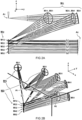
- FIG 1A schematically illustrates a satellite 100 comprising an imager 10.
- FIG 1B schematically illustrates a top view of an embodiment for a multi-angle imager 10.
- FIG 2A schematically illustrates a side view of the embodiment.
- FIG 2B schematically illustrates a perspective view of the embodiment.
- the multi-angle imager 10 comprises at least one entrance pupil A1 configured to pass through light beams Li of an object P0 to be imaged from multiple entry angles ⁇ i into the imager 10.
- the imager may comprise multiple entrance pupils, e.g. one for each imaging branch.
- multi aperture can be used instead of single aperture to minimize angle of incidence on Mi1 and Mi2 mirrors.
- the entrance pupil can be described as the optical image of the physical aperture stop, as 'seen' through the front of the imaging system. It is typically, located at the vertex of the imager's angle of view.
- the imaging array Mij is configured to receive the light beams Li via the one or more entrance pupils A1 according to distinct fields of view Vi of the object P0 along each of the multiple entry angles ⁇ i.
- the imaging array Mij is configured to image subsections Si of the object P according to the distinct fields of view Vi onto an imaging plane P1.
- the imaging plane P1 can be at the surface of a detector (not shown here).
- an (intermediate) imaging plane is at a slit (not shown here).
- the imaging array Mij comprises multiple imaging branches, e.g. indicated in FIG 2B by the references M1j,M2j.
- the imaging branches are configured to form respective optical paths for the light beams through the imager 10 for imaging the respective subsections of the object P0.
- Each imaging branch comprises a distinct set of optical elements, e.g. the mirrors M11,M12 for imaging branch M1j.
- the optical elements in each imaging branch are configured to receive the respective light beam along the respective entry angle ⁇ 1 and redirect the respective light beam towards the imaging plane P1 (or intermediate imaging plane).
- the light beams L1,L2 from each of the multiple imaging branches M1j,M2j are redirected to travel in a common direction "y" between the imaging array Mij and the imaging plane P1. More preferably, the redirected light beams travel along substantially parallel paths in the common direction "y". For example, the paths are parallel to within ten degrees plane angle, or less, e.g. within five degrees, or even within one degree, or less than a tenth of a degree.
- the imaging array Mij is configured to combine the incoming light beams Li to have a common effective focal plane at a slit (not shown here).
- the imaging branches M1j,M2j may have optical elements each having different curvatures but the branches preferably have a focal length optimized to achieve a common size on the detector for each Si.
- the imaging branch for each angle may have its own distinct focal length in order to achieve common magnification of each strip on the detector
- the plurality of beams can be effectively treated as a single extended beam.
- This has the advantage that further optical elements in an optical path after the imaging array Mij can be combined or integrated.
- a single polarization modulation optics (not shown here) can be used to modulate the multiple beams
- a single grating (not shown here) can be used to spectrally dissolve the multiple beams
- one mirror or lens (not shown here) can be used to collimate or focus the multiple beams
- single spectral filter single 50/50 splitter, single beam splitter or single Philips-prism, et cetera.
- the light beams L1,L2 from each of the multiple imaging branches M1j,M2j are stacked in a line or row along a direction "z" transverse to their direction of travel "y".
- the multiple imaging branches M1j,M2j are configured to stack their respective light beams one above the other along a direction "z" transverse to a plane (x,y) spanned by the multiple entry angles ⁇ i.
- each imaging branch M1j has its own set of at least two optical elements M11,M12.
- the optical elements are distinct from any other imaging branch M2j.
- each imaging branch M1j,M2j has a distinct primary mirror M11,M21.
- the primary mirrors Mi1 are distributed to receive the light beams Li from the one or more entrance pupils A1 at a range of multiple entry angles ⁇ i.
- the primary mirrors Mi1 have a concave reflecting surface to at least partially focus the reflected beams.
- each imaging branch M1j,M2j has a distinct secondary mirror M12,M22.
- the secondary mirrors Mi2 are stacked in a row to receive the light beams Li reflected from the primary mirrors Mi1 and reflect parallel light beams in a common direction.
- the secondary mirrors Mi2 have a concave reflecting surface e.g. to at least partially collimate or focus the reflected beams.
- the secondary mirrors Mi2 can be convex in some designs, e.g. with three mirrors per imaging branch.
- the directions of the primary, secondary, and optionally further mirrors of each of the imaging branches are distinctly oriented to provide a common direction of the light beams exiting the imaging array Mij.
- the primary, secondary, and optionally further mirrors of each of the imaging branches are distinctly curved to provide a common focal length between the imaging branches.
- the corresponding mirrors for different imaging branches can have different radii of curvature but as a set provide the same effective focal length.
- a common focal length can be achieved by adjusting mirror separation of the mirrors and/or their radius of curvature.
- off-axis mirrors are used; alternatively, or in addition, also on-axis mirrors may be used.
- the mirror surfaces can be described by a biconic design.
- the biconic design can e.g. be arranged to provide a desired anamorphic ratio.
- a pupil stop can be positioned at any (intermediate) focal point of the telescope system.
- the optical elements adjacent imaging branches M1j,M2j are preferably distinct.
- corresponding optical elements of different imaging branches M1j,M2j are separate from each other, e.g. spaced apart.
- each optical surface provides a distinct optical function.
- each optical surface has its own geometric definition.
- the optical elements may be interconnected but with an optical discontinuity between the optical surfaces.
- the stack of secondary mirrors can be embodied as a monolithic element with stepped reflective surfaces (not shown).
- the combination of a concave primary mirror and concave secondary mirror may form a so-called Gregorian telescope.
- each imaging branch can have a distinct (off-axis) Gregorian telescope design.
- the combination of a concave primary mirror and convex secondary mirror may form a so-called Cassegrain telescope.
- each imaging branch can have a distinct off-axis Cassegrain telescope design.
- the same optical functionality as described herein can also be provided by more than two optical elements per imaging branch, e.g.
- mirrors though at the cost of extra weight. Also other combinations of convex/concave elements can be used to provide similar optical results. Alternative, or in addition to mirrors, also lenses can be used. While the current embodiment shows five imaging branches, there can also be more or less, e.g. two, three, four, five, six, seven, eight, nine, or more.
- FIG 3 schematically illustrates the multi-angle imager 10.
- the optical elements M11,M12 in each imaging branch M1j are configured to focus their respective light beam L1 onto a slit A2.
- the multiple imaging branches M1j,M2j are configured to project respective images of the respective subsections S1,S2 onto a slit A2.
- the images are extended along a length direction "z" of the slit A2 to provide spatial information of the respective subsections S1,S2 at least along said length direction "z", while the width direction "x" of the slit A2 can be used for e.g. subsequent spectral and/or polarization analysis.
- the subsections S1,S2 of the object P0 to be imaged have a length that is greater than their width by at least a factor two, three, five, or more, e.g. a factor ten.
- the system can be modified by adding (folding) mirrors, e.g. at the position currently indicated A2 to relocate the aperture, slit or lens set. Possibly, this may further compactify the system.
- the imager 10 is combined with polarization modulation optics PMO to form a multi-angle spectropolarimeter.
- the spectropolarimeter comprises a single integrated polarization modulator optics (PMO), preferably disposed in a plurality of light beams Li after the imaging array Mij.
- the light beams can be stacked parallel and imaged at the slit A2.
- the PMO is disposed near the slit A2, e.g. directly adjacent the slit either before or behind the slit.
- the PMO is an integrated device e.g. according to the article by Rietjens et al discussed in the background section.
- the polarization modulator optics PMO comprises an athermal multiple-order retarder, e.g. MgF2 + sapphire crystals, a polarizing beam splitter, e.g. Wollaston prism. and an achromatic quarter-wave retarder, e.g. Fresnel rhomb.
- an imager e.g. photo-elastic modulation
- embodiments with (polarizing) beam splitters in combination with a (spectral) imager e.g. a spectral imager comprising stripe bandpass and/or polarization filters on the detector could be used in combination with a multi-angle telescope.
- the imager 10 is combined with a single spectral dissolving element 21 and/or imaging sensor 22 to form a multi-angle spectrometer 20.
- the multi-angle spectrometer 20 has as a single grating or prism configured to resolve the plurality of light beams Li traveling in parallel and/or having common degree of collimation.
- the spectrally resolved light beams Li are imaged onto a single detector surface, e.g. pixel array. While not all depicted in the schematic figure, typically a spectrometer comprises the following elements: collimator, spectrally dissolving element, objective; these are typically followed by a single detector surface, e.g. pixel array.
- FIGs 4A and 4B schematically illustrate the effect of separating adjacent fields of view V1,V2,V3.
- each imaging branch M1j together with the respective entrance pupil A1 may define a respective field of view V1.
- the fields of view V1,V2,V3 can be characterized by the respective spatial extent DS of the imaged subsection S1,S2,S3 on the object P0.
- the field of view V1 can be characterized by the maximum opening angle Do of the respective light beam that can enter the entrance pupils A1 and be imaged by the respective imaging branch M1j.
- the opening angle of a field of view can also be referred to as the angle of view.
- the field of view V1 may be determined by a spatial extent of the entrance pupil A1, a spatial extend of a field-limiting aperture at an intermediate position, the primary or further imaging mirrors, and their relative positions.
- the field of view can be determined by ray tracing an optical design, e.g. determining the limits of rays that can be projected onto the detector via the imaging array back from the entrance pupil.
- the object P0 is not imaged before entering the imaging array Mij.
- the object P0 need not be imaged at the entrance pupils A1.
- the imaging array Mij may have a single object plane namely at the distance of the object P0 to be imaged. Because the present design does not need to rely on an intermediate object plane, an additional projection system in front of the entrance pupil A1 can be omitted which saves excess weight. However, it should preferably be prevented that the light from adjacent fields of view gets mixed up, ending in the wrong detection channel. In this regard it is advantageous that the fields of view in a multi-angle imager 10 are typically separate.
- FIG 4B the fields of view are less separated than in FIG 4A .
- the lack of sufficient separation may cause stray light rays L1', L3' from the adjacent sections S1,S3 to enter the wrong imaging branch M2j', which is prevented in FIG 4A where the light rays L1', L3' cannot directly hit imaging branch M2j'.
- adjacent fields of view V1,V2 or V2,V3 are separated by non-imaged parts N of the object P0 there between.
- an angular separation D ⁇ between center lines of adjacent fields of views V2,V3 is higher than an (average) opening angle Do of said adjacent fields of views V2,V3, e.g. higher by more than one percent, ten percent, twenty percent, fifty percent, or even more than a factor two, five, ten, or more e.g. a factor hundred.
- the higher the angular separation D ⁇ compared to the opening angle Do the less stray light of one field of view may bleed into an adjacent field of view.
- adjacent subsections S1,S2 of the object P0 to be imaged are spaced apart by non-imaged sections N of the object P0.
- a spatial extent DN of the non-imaged sections N between adjacent imaged subsections S1,S2 of the object P0 s more than one percent of a spatial extent DS said adjacent imaged subsections S1,S2, preferably more than ten percent, twenty percent, fifty percent, or even more than a factor two, five, ten, or more e.g. a factor hundred.
- the spatial or angular separation between adjacent views is sufficient to prevent light from one imaged subjection to end up in the image of an adjacent subsection, e.g. wherein at least ninety percent of the light in an image actually originates from the respective subsection, preferably more than ninety-nine percent, more than 99.9%, or practically all of the registered light.
- the entrance pupil A1 is sufficiently wide to prevent bending of the entering light beams.
- the spatial extent of the pupil is preferably higher than a coherence length of the light, e.g. by a factor of two, five, ten, hundred, or more, so that the light generally travels in a straight line through the entrance pupil A1 and is minimally affected by diffraction effects.
- the imager 10 is integrated in a satellite 100, e.g. as shown in FIG1A , or other orbiting or in-situ platform.
- the object P0 to be imaged is a planet surface or atmosphere.
- the satellite 100 may typically operate at a distance of a few hundred kilometers or more from the planet surface.
- the subsections Si to be imaged comprise rectangular swaths of the planet having typical dimensions of about ten by hundred kilometer. Of course also other dimensions are possible.
- Typical viewing angles ⁇ i may be for example, angles of 0, ⁇ 14, ⁇ 28, ⁇ 42, and ⁇ 56 degrees; or 0, ⁇ 20, ⁇ 50; or 0, ⁇ 35, ⁇ 50. Of course also other angles are possible.
- Various aspects as described herein can also be embodied as a method to simultaneously image different subsections of an object with the multi-angle imager.
- Some embodiments light beams of an object to be imaged are passed from multiple entry angles ⁇ i through one or more entrance pupils into the imager.
- Some embodiments comprise receiving the light beams via the one or more entrance pupils according to distinct fields of view of the object along each of the multiple entry angles onto an imaging array.
- Some embodiments comprise imaging the subsections Si of the object P according to the distinct fields of view Vi onto an imaging plane P 1.
- optical elements such as mirrors or gratings may be combined split up, or replaced by one or more alternative components such as lenses and/or prisms.
- the various elements of the embodiments as discussed and shown offer certain advantages, such as reduction of weight and improving compactness/robustness.
- any one of the above embodiments or processes may be combined with one or more other embodiments or processes to provide even further improvements in finding and matching designs and advantages.
- this disclosure offers particular advantages to the deployment of a multi-angle imager in a satellite or airplane, and in general can be applied for any application of a light weight multi-angle imager, optionally combined with an imaging sensor, spectroscope, polarimeter, et cetera.
- some aspects as described herein may be applicable for e.g. fast temporal modulation using photo-elastic modulators.
- Some aspects may also be used to form a multi-angle polarimeter in which the polarimetry is performed using temporal modulation (filter wheel) or amplitude splitting.
Landscapes
- Physics & Mathematics (AREA)
- Spectroscopy & Molecular Physics (AREA)
- General Physics & Mathematics (AREA)
- Optics & Photonics (AREA)
- Spectrometry And Color Measurement (AREA)
Description
- The present disclosure relates to a multi-angle imager and a method to simultaneously image different subsections of an object, e.g. planetary surface at different angles.
- As background,
WO 03/067305 A1 US 2012/0105593 A1 describes a multi-view video and still 3D capture system.WO 2007/095743 A1 describes an optically multiplexed imaging systems and methods of operation. - For example, in an article titled "SPEX: The Spectropolarimeter For Planetary Exploration" (International Conference on Space Optics 2010), Rietjens et al describe a multi-angle spectropolarimeter designed to operate from an orbiting or in situ platform. Its purpose is to simultaneously measure the radiance and the state (degree and angle) of linear polarization of sunlight that has been scattered in a planetary atmosphere and/or reflected by the planetary surface. Light is received from multiple angles corresponding to respective swaths of the planetary surface to be imaged. As explained, the degree of linear polarization is sensitive to the microphysical properties of atmospheric or surface particles (such as size, shape, and composition), and to the vertical distribution of atmospheric particles, such as cloud top altitudes. Such measurements can thus be used for disentangling many parameters that describe planetary atmospheres and surfaces. SPEX uses a passive method for its radiance and polarization observations that is based on a carefully selected combination of polarization optics. This method, called spectral modulation, is the modulation of the radiance spectrum in both amplitude and phase by the degree and angle of linear polarization, respectively. The polarization optics consists of an achromatic quarter-wave retarder, an athermal multiple-order retarder, and a polarizing beam splitter. In the design, it is shown that each branch of optics is provided with its own polarization optics placed behind respective apertures.
- There is a need to further improve the design of multi-angled imagers e.g. with regards to compactness, robustness and weight reduction.
- Aspects of the present disclosure relate to multi-angle imagers and methods to simultaneously image different subsections of an object. The imager comprises one or more entrance pupils configured to pass through light beams of an object to be imaged from multiple entry angles into the imager. The imaging array is configured to receive the light beams via the one or more entrance pupils according to distinct fields of view of the object along each of the multiple entry angles. The imaging array is further configured to image subsections of the object according to the distinct fields of view onto an imaging plane. As described herein the imaging array comprises multiple imaging branches configured to form respective optical paths for the light beams through the imager for imaging the respective subsections of the object.
- By providing each imaging branch with a distinct set of optical elements to receive and redirect the respective light beams, complicated freeform optical surfaces can be avoided and weight of unused intermediate surfaces can be omitted. By redirecting the light beams from each of the multiple imaging branches to travel in a common direction, further elements such polarization optics can be integrated to act on all beams simultaneously, instead of using separate optics for each of the beams. This can further reduce weight. By having the redirected light beams travel along substantially parallel paths in the common direction, the optical effects on each of the beams can be more homogeneous and the design less complicated. By combining the incoming light beams to have a common effective focal plane, e.g. at an imaging sensor or slit, the multiple beams can be effectively treated as a single extended beam improving robustness and further reducing complexity. By stacking the light beams from each of the multiple imaging branches, the multiple beams can form a combined image particularly suitable for the entrance slit of a spectrometer. For example, multiple sections can be spectrally dissolved using a single spectrometer to reduce weight. By imaging distinct fields of view, separated by non-imaged sections there between, it can be prevented that light of one section mixes in the image of another section, even without slicing the field in an intermediate image plane. In this way an additional optical "image slicer" system placed after the telescope can be omitted and additional weight and complexity avoided. An image slicer system is a re-imager that includes an optical element placed in an intermediate image that slices the field.
- These and other features, aspects, and advantages of the apparatus, systems and methods of the present disclosure will become better understood from the following description, appended claims, and accompanying drawing wherein:
-
FIG 1A schematically illustrates a satellite comprising an imager as described herein; -
FIG 1B schematically illustrates a top view of an embodiment for a multi-angle imager; -
FIG 2A schematically illustrates a side view of the embodiment; -
FIG 2B schematically illustrates a perspective view of the embodiment; -
FIG 3 schematically illustrates another embodiment of a multi-angle imager combined with polarization modulation optics and a spectrometer. -
FIGs 4A and 4B schematically illustrate the effect of separating adjacent fields of view. - Terminology used for describing particular embodiments is not intended to be limiting of the invention. As used herein, the singular forms "a", "an" and "the" are intended to include the plural forms as well, unless the context clearly indicates otherwise. The term "and/or" includes any and all combinations of one or more of the associated listed items. It will be understood that the terms "comprises" and/or "comprising" specify the presence of stated features but do not preclude the presence or addition of one or more other features. It will be further understood that when a particular step of a method is referred to as subsequent to another step, it can directly follow said other step or one or more intermediate steps may be carried out before carrying out the particular step, unless specified otherwise. Likewise it will be understood that when a connection between structures or components is described, this connection may be established directly or through intermediate structures or components unless specified otherwise.
- The invention is described more fully hereinafter with reference to the accompanying drawings, in which embodiments of the invention are shown. In the drawings, the absolute and relative sizes of systems, components, layers, and regions may be exaggerated for clarity. Embodiments may be described with reference to schematic and/or cross-section illustrations of possibly idealized embodiments and intermediate structures of the invention. In the description and drawings, like numbers refer to like elements throughout. Relative terms as well as derivatives thereof should be construed to refer to the orientation as then described or as shown in the drawing under discussion. These relative terms are for convenience of description and do not require that the system be constructed or operated in a particular orientation unless stated otherwise.
-
FIG 1A schematically illustrates asatellite 100 comprising animager 10.FIG 1B schematically illustrates a top view of an embodiment for amulti-angle imager 10.FIG 2A schematically illustrates a side view of the embodiment.FIG 2B schematically illustrates a perspective view of the embodiment. - The
multi-angle imager 10 comprises at least one entrance pupil A1 configured to pass through light beams Li of an object P0 to be imaged from multiple entry angles αi into theimager 10. In other embodiment (not shown), the imager may comprise multiple entrance pupils, e.g. one for each imaging branch. For example, multi aperture can be used instead of single aperture to minimize angle of incidence on Mi1 and Mi2 mirrors. Generally, the entrance pupil can be described as the optical image of the physical aperture stop, as 'seen' through the front of the imaging system. It is typically, located at the vertex of the imager's angle of view. - The imaging array Mij is configured to receive the light beams Li via the one or more entrance pupils A1 according to distinct fields of view Vi of the object P0 along each of the multiple entry angles αi. The imaging array Mij is configured to image subsections Si of the object P according to the distinct fields of view Vi onto an imaging plane P1. For example, the imaging plane P1 can be at the surface of a detector (not shown here).
- In addition, an (intermediate) imaging plane is at a slit (not shown here).
- The imaging array Mij comprises multiple imaging branches, e.g. indicated in
FIG 2B by the references M1j,M2j. The imaging branches are configured to form respective optical paths for the light beams through theimager 10 for imaging the respective subsections of the object P0. Each imaging branch comprises a distinct set of optical elements, e.g. the mirrors M11,M12 for imaging branch M1j. The optical elements in each imaging branch are configured to receive the respective light beam along the respective entry angle α1 and redirect the respective light beam towards the imaging plane P1 (or intermediate imaging plane). - As shown in
FIG 2A , the light beams L1,L2 from each of the multiple imaging branches M1j,M2j are redirected to travel in a common direction "y" between the imaging array Mij and the imaging plane P1. More preferably, the redirected light beams travel along substantially parallel paths in the common direction "y". For example, the paths are parallel to within ten degrees plane angle, or less, e.g. within five degrees, or even within one degree, or less than a tenth of a degree. The imaging array Mij is configured to combine the incoming light beams Li to have a common effective focal plane at a slit (not shown here). For example, the imaging branches M1j,M2j may have optical elements each having different curvatures but the branches preferably have a focal length optimized to achieve a common size on the detector for each Si. For imaging sections of e.g. a planet under various angles, the imaging branch for each angle may have its own distinct focal length in order to achieve common magnification of each strip on the detector - By providing the light beams with a common direction and common effective focal plane or collimation, the plurality of beams can be effectively treated as a single extended beam. This has the advantage that further optical elements in an optical path after the imaging array Mij can be combined or integrated. For example, a single polarization modulation optics (not shown here) can be used to modulate the multiple beams, a single grating (not shown here) can be used to spectrally dissolve the multiple beams, one mirror or lens (not shown here) can be used to collimate or focus the multiple beams, single spectral filter, single 50/50 splitter, single beam splitter or single Philips-prism, et cetera. It will be appreciated that this combination or integration of optical elements can save weight and/or improve robustness and/or manufacturability.
- As shown in
FIGS 2A and 2B , the light beams L1,L2 from each of the multiple imaging branches M1j,M2j are stacked in a line or row along a direction "z" transverse to their direction of travel "y". The multiple imaging branches M1j,M2j are configured to stack their respective light beams one above the other along a direction "z" transverse to a plane (x,y) spanned by the multiple entry angles αi. - In some embodiments, each imaging branch M1j has its own set of at least two optical elements M11,M12. For example, the optical elements are distinct from any other imaging branch M2j. In a preferred embodiment, each imaging branch M1j,M2j has a distinct primary mirror M11,M21. Preferably, the primary mirrors Mi1 are distributed to receive the light beams Li from the one or more entrance pupils A1 at a range of multiple entry angles αi. Typically, the primary mirrors Mi1 have a concave reflecting surface to at least partially focus the reflected beams. In another or further preferred embodiment, each imaging branch M1j,M2j has a distinct secondary mirror M12,M22. Preferably, the secondary mirrors Mi2 are stacked in a row to receive the light beams Li reflected from the primary mirrors Mi1 and reflect parallel light beams in a common direction. In some embodiments, the secondary mirrors Mi2 have a concave reflecting surface e.g. to at least partially collimate or focus the reflected beams. Alternatively, the secondary mirrors Mi2 can be convex in some designs, e.g. with three mirrors per imaging branch.
- Preferably, the directions of the primary, secondary, and optionally further mirrors of each of the imaging branches are distinctly oriented to provide a common direction of the light beams exiting the imaging array Mij. Preferably, the primary, secondary, and optionally further mirrors of each of the imaging branches are distinctly curved to provide a common focal length between the imaging branches. For example, the corresponding mirrors for different imaging branches can have different radii of curvature but as a set provide the same effective focal length. In some embodiments, a common focal length can be achieved by adjusting mirror separation of the mirrors and/or their radius of curvature. In some embodiments off-axis mirrors are used; alternatively, or in addition, also on-axis mirrors may be used. In some embodiments, the mirror surfaces can be described by a biconic design. The biconic design can e.g. be arranged to provide a desired anamorphic ratio. In some embodiments it is preferred to have a telecentric image space. To achieve this, a pupil stop can be positioned at any (intermediate) focal point of the telescope system.
- The optical elements adjacent imaging branches M1j,M2j are preferably distinct. For example, corresponding optical elements of different imaging branches M1j,M2j are separate from each other, e.g. spaced apart. Typically each optical surface provides a distinct optical function. For example, each optical surface has its own geometric definition. In some cases, the optical elements may be interconnected but with an optical discontinuity between the optical surfaces. For example, the stack of secondary mirrors can be embodied as a monolithic element with stepped reflective surfaces (not shown).
- In some embodiments, the combination of a concave primary mirror and concave secondary mirror may form a so-called Gregorian telescope. In the current design it is preferred to use separate imaging branches for each of the multiple entry angles αi. For example, each imaging branch can have a distinct (off-axis) Gregorian telescope design. Alternatively, the combination of a concave primary mirror and convex secondary mirror may form a so-called Cassegrain telescope. In the current design it is preferred to use separate imaging branches for each of the multiple entry angles αi. For example, each imaging branch can have a distinct off-axis Cassegrain telescope design. Of course the same optical functionality as described herein can also be provided by more than two optical elements per imaging branch, e.g. three, or more mirrors, though at the cost of extra weight. Also other combinations of convex/concave elements can be used to provide similar optical results. Alternative, or in addition to mirrors, also lenses can be used. While the current embodiment shows five imaging branches, there can also be more or less, e.g. two, three, four, five, six, seven, eight, nine, or more.
-
FIG 3 schematically illustrates themulti-angle imager 10. - In some embodiments, the optical elements M11,M12 in each imaging branch M1j are configured to focus their respective light beam L1 onto a slit A2. The multiple imaging branches M1j,M2j are configured to project respective images of the respective subsections S1,S2 onto a slit A2. The images are extended along a length direction "z" of the slit A2 to provide spatial information of the respective subsections S1,S2 at least along said length direction "z", while the width direction "x" of the slit A2 can be used for e.g. subsequent spectral and/or polarization analysis. In some embodiments, the subsections S1,S2 of the object P0 to be imaged have a length that is greater than their width by at least a factor two, three, five, or more, e.g. a factor ten. In some embodiments (not shown), the system can be modified by adding (folding) mirrors, e.g. at the position currently indicated A2 to relocate the aperture, slit or lens set. Possibly, this may further compactify the system. In some embodiment there is no slit but only an image plane, i.e. the subsections S1,S2 are imaged with their length along the x-direction and width along the z-direction (x=swath, z=viewing angle).
- In some embodiments, as shown, the
imager 10 is combined with polarization modulation optics PMO to form a multi-angle spectropolarimeter. In some embodiments, the spectropolarimeter comprises a single integrated polarization modulator optics (PMO), preferably disposed in a plurality of light beams Li after the imaging array Mij. In some embodiments, the light beams can be stacked parallel and imaged at the slit A2. In a preferred embodiment, the PMO is disposed near the slit A2, e.g. directly adjacent the slit either before or behind the slit. Preferably, the PMO is an integrated device e.g. according to the article by Rietjens et al discussed in the background section. For example, the polarization modulator optics PMO comprises an athermal multiple-order retarder, e.g. MgF2 + sapphire crystals, a polarizing beam splitter, e.g. Wollaston prism. and an achromatic quarter-wave retarder, e.g. Fresnel rhomb. Also possible are embodiments with other polarization modulation optics in combination with an imager (e.g. photo-elastic modulation) or embodiments with (polarizing) beam splitters in combination with a (spectral) imager. E.g. a spectral imager comprising stripe bandpass and/or polarization filters on the detector could be used in combination with a multi-angle telescope. - In some embodiments, as shown, the
imager 10 is combined with a singlespectral dissolving element 21 and/orimaging sensor 22 to form amulti-angle spectrometer 20. Preferably themulti-angle spectrometer 20 has as a single grating or prism configured to resolve the plurality of light beams Li traveling in parallel and/or having common degree of collimation. In some embodiments, the spectrally resolved light beams Li are imaged onto a single detector surface, e.g. pixel array. While not all depicted in the schematic figure, typically a spectrometer comprises the following elements: collimator, spectrally dissolving element, objective; these are typically followed by a single detector surface, e.g. pixel array. -
FIGs 4A and 4B schematically illustrate the effect of separating adjacent fields of view V1,V2,V3. - As shown, each imaging branch M1j together with the respective entrance pupil A1 may define a respective field of view V1.For example, the fields of view V1,V2,V3 can be characterized by the respective spatial extent DS of the imaged subsection S1,S2,S3 on the object P0. Alternatively, or in addition, the field of view V1 can be characterized by the maximum opening angle Do of the respective light beam that can enter the entrance pupils A1 and be imaged by the respective imaging branch M1j. The opening angle of a field of view can also be referred to as the angle of view. For example, the field of view V1 may be determined by a spatial extent of the entrance pupil A1, a spatial extend of a field-limiting aperture at an intermediate position, the primary or further imaging mirrors, and their relative positions. For example, the field of view can be determined by ray tracing an optical design, e.g. determining the limits of rays that can be projected onto the detector via the imaging array back from the entrance pupil.
- In a preferred embodiment, the object P0 is not imaged before entering the imaging array Mij. For example, the object P0 need not be imaged at the entrance pupils A1. In other words, the imaging array Mij may have a single object plane namely at the distance of the object P0 to be imaged. Because the present design does not need to rely on an intermediate object plane, an additional projection system in front of the entrance pupil A1 can be omitted which saves excess weight. However, it should preferably be prevented that the light from adjacent fields of view gets mixed up, ending in the wrong detection channel. In this regard it is advantageous that the fields of view in a
multi-angle imager 10 are typically separate. - For example, in
FIG 4B the fields of view are less separated than inFIG 4A . As illustrated inFIG 4B , the lack of sufficient separation may cause stray light rays L1', L3' from the adjacent sections S1,S3 to enter the wrong imaging branch M2j', which is prevented inFIG 4A where the light rays L1', L3' cannot directly hit imaging branch M2j'. - Therefore it is preferred in some embodiments that adjacent fields of view V1,V2 or V2,V3 are separated by non-imaged parts N of the object P0 there between. For example, an angular separation Dα between center lines of adjacent fields of views V2,V3 is higher than an (average) opening angle Do of said adjacent fields of views V2,V3, e.g. higher by more than one percent, ten percent, twenty percent, fifty percent, or even more than a factor two, five, ten, or more e.g. a factor hundred. The higher the angular separation Dα compared to the opening angle Do, the less stray light of one field of view may bleed into an adjacent field of view.
- Alternatively, or in addition, it is preferred in some embodiments that adjacent subsections S1,S2 of the object P0 to be imaged are spaced apart by non-imaged sections N of the object P0. Preferably, a spatial extent DN of the non-imaged sections N between adjacent imaged subsections S1,S2 of the object P0 s more than one percent of a spatial extent DS said adjacent imaged subsections S1,S2, preferably more than ten percent, twenty percent, fifty percent, or even more than a factor two, five, ten, or more e.g. a factor hundred. The higher the spatial separation DN between the adjacent imaged subsections S1,S2, the less stray light of one imaged subsection S1 may bleed into the image of an adjacent subsection S2.
- Preferably, the spatial or angular separation between adjacent views is sufficient to prevent light from one imaged subjection to end up in the image of an adjacent subsection, e.g. wherein at least ninety percent of the light in an image actually originates from the respective subsection, preferably more than ninety-nine percent, more than 99.9%, or practically all of the registered light. Preferably, the entrance pupil A1 is sufficiently wide to prevent bending of the entering light beams. For example, the spatial extent of the pupil is preferably higher than a coherence length of the light, e.g. by a factor of two, five, ten, hundred, or more, so that the light generally travels in a straight line through the entrance pupil A1 and is minimally affected by diffraction effects.
- In some embodiments, the
imager 10 is integrated in asatellite 100, e.g. as shown inFIG1A , or other orbiting or in-situ platform. For example, the object P0 to be imaged is a planet surface or atmosphere. For example, thesatellite 100 may typically operate at a distance of a few hundred kilometers or more from the planet surface. For example, the subsections Si to be imaged comprise rectangular swaths of the planet having typical dimensions of about ten by hundred kilometer. Of course also other dimensions are possible. Typical viewing angles αi may be for example, angles of 0, ±14, ±28, ±42, and ±56 degrees; or 0,±20,±50; or 0,±35,±50. Of course also other angles are possible. - For the purpose of clarity and a concise description, features are described herein as part of the same or separate embodiments, however, it will be appreciated that the scope of the invention may include embodiments having combinations of all or some of the features described. Various aspects as described herein can also be embodied as a method to simultaneously image different subsections of an object with the multi-angle imager. Some embodiments light beams of an object to be imaged are passed from multiple entry angles αi through one or more entrance pupils into the imager. Some embodiments comprise receiving the light beams via the one or more entrance pupils according to distinct fields of view of the object along each of the multiple entry angles onto an imaging array. Some embodiments comprise imaging the subsections Si of the object P according to the distinct fields of view Vi onto an
imaging plane P 1. - While embodiments were shown for particular optical arrangements, also alternative ways may be envisaged by those skilled in the art having the benefit of the present disclosure for achieving a similar function and result. E.g. optical elements such as mirrors or gratings may be combined split up, or replaced by one or more alternative components such as lenses and/or prisms. The various elements of the embodiments as discussed and shown offer certain advantages, such as reduction of weight and improving compactness/robustness. Of course, it is to be appreciated that any one of the above embodiments or processes may be combined with one or more other embodiments or processes to provide even further improvements in finding and matching designs and advantages.
- It is appreciated that this disclosure offers particular advantages to the deployment of a multi-angle imager in a satellite or airplane, and in general can be applied for any application of a light weight multi-angle imager, optionally combined with an imaging sensor, spectroscope, polarimeter, et cetera. For example, some aspects as described herein may be applicable for e.g. fast temporal modulation using photo-elastic modulators. Some aspects may also be used to form a multi-angle polarimeter in which the polarimetry is performed using temporal modulation (filter wheel) or amplitude splitting. It allows for higher spatial resolution with wide field-of-view imagers, allows for optimizing the spatial resolution and swath over the viewing angle range beyond a f-tan(theta) mapping while maintaining a single detector for imaging the set of distinct subsections of an object. It is also a solution that benefits from the small exposure to space via small entrance apertures, in contrast to the lens-based designs.
- In interpreting the appended claims, it should be understood that the word "comprising" does not exclude the presence of other elements or acts than those listed in a given claim; the word "a" or "an" preceding an element does not exclude the presence of a plurality of such elements: any reference signs in the claims do not limit their scope; several "means" may be represented by the same or different item(s) or implemented structure or function; any of the disclosed devices or portions thereof may be combined together or separated into further portions unless specifically stated otherwise. Where one claim refers to another claim, this may indicate synergetic advantage achieved by the combination of their respective features. But the mere fact that certain measures are recited in mutually different claims does not indicate that a combination of these measures cannot also be used to advantage. The present embodiments may thus include all working combinations of the claims wherein each claim can in principle refer to any preceding claim unless clearly excluded by context.
Claims (13)
- A multi-angle imager (10) comprising- one or more entrance pupils (A1) configured to pass through light beams (Li) of an object (P0) to be imaged from multiple entry angles (αi) into the imager (10);- an imaging array (Mij) configured too receive the light beams (Li) via the one or more entrance pupils (A1) according to distinct fields of view (Vi) of the object (P0) along each of the multiple entry angles (αi), ando to image subsections (Si) of the object (P) according to the distinct fields of view (Vi) onto an imaging plane (P1);- wherein the imaging array (Mij) comprises multiple imaging branches (M1j,M2j) configured to form respective optical paths for the light beams (L1,L2) through the imager (10) for imaging the respective subsections (S1,S2) of the object (P0);- wherein each imaging branch (Mij) comprises a distinct set of optical elements (M11,M12) configured to∘ receive the respective light beam (L1) along the respective entry angle (α1) and∘ redirect the respective light beam (L1) towards the imaging plane (P1);- wherein the light beams (L1,L2) from each of the multiple imaging branches (M1j,M2j) are redirected to travel in a common direction (y) between the imaging array (Mij) and the imaging plane (P1);wherein the multiple imaging branches (M1j,M2j) are configured to stack their respective light beams one above the other along a first direction (z) transverse to a plane (x,y) spanned by the multiple entry angles (αi);wherein the multiple imaging branches (M1j,M2j) are configured to project respective images of the respective subsections (S1,S2) onto a slit (A2), wherein the images are extended along the first direction (z), corresponding to a length of the slit (A2), to provide spatial information of the respective subsections (S1,S2) along said first direction (z), wherein a second direction (x), transverse to the first direction (z) and corresponding to a width of the slit (A2), is used for subsequent spectral analysis of the images.
- The multi-angle imager according to claim 1, wherein the redirected light beams travel along substantially parallel paths in the common direction (y)
- The multi-angle imager according to any of the preceding claims, wherein the imaging array (Mij) is configured to combine the incoming light beams (Li) to have a common effective focal plane.
- The multi-angle imager according to any of the preceding claims, wherein the light beams (L1,L2) from each of the multiple imaging branches (M1j,M2j) are stacked in a row along a direction (z) transverse to their direction of travel (y).
- The multi-angle imager according to any of the preceding claims, wherein the object (P0) is not imaged before entering the imaging array (Mij).
- The multi-angle imager according to any of the preceding claims, wherein adjacent fields of view (V1,V2; V2,V3) are separated by non-imaged parts (N) of the object (P0) there between, wherein the spatial or angular separation between adjacent views is sufficient to prevent light (L1') from one imaged subjection (S1) to end up in the image of an adjacent subsection (S2).
- The multi-angle imager according to any of the preceding claims, wherein each imaging branch (M1j) has its own set of at least two optical elements (M11,M12) distinct from any other imaging branch (M2j).
- The multi-angle imager according to any of the preceding claims, wherein corresponding optical elements of different imaging branches (M1j,M2j) are separate from each other, wherein each optical surface provides a distinct optical function.
- The multi-angle imager according to any of the preceding claims, wherein- each imaging branch (M1j,M2j) has at least a distinct primary mirror (M11,M21), wherein the primary mirrors (Mil) are distributed to receive the light beams (Li) from the one or more entrance pupils (A1) at a range of multiple entry angles (αi);- each imaging branch (M1j,M2j) has at least a distinct secondary mirror (M12,M22), wherein the secondary mirrors (Mi2) are stacked in a row to receive the light beams (Li) reflected from the primary mirrors (Mil) and reflect parallel light beams in a common direction;- wherein the directions of the at least primary and secondary mirrors of each of the imaging branches are distinctly oriented to provide a common direction of the light beams exiting the imaging array (Mij)- wherein the at least primary and secondary mirrors of each of the imaging branches are distinctly curved to provide a common focal length between the imaging branches.
- A multi-angle spectropolarimeter comprising the imager (10) according to any of the preceding claims, wherein a single integrated polarization modulator optics (PMO) is disposed in a plurality of light beams travelling in a common direction (Li) after the imaging array (Mij).
- A multi-angle spectrometer comprising the imager (10) according to any of the preceding claims, wherein a single spectral dissolving element is configured to resolve the plurality of light beams (Li), wherein the spectrally resolved light beams (Li) are imaged onto a pixel array.
- A satellite (100) comprising the multi-angle imager, spectropolarimeter , and/or spectrometer according to any of the preceding claims, wherein the object (P0) to be imaged is a planet surface or atmosphere.
- Use of the multi-angle imager, spectrometer, spectropolarimeter, and/or satellite according to any of the preceding claims for simultaneously imaging different subsections (S1,S2) of an object (P0).
Applications Claiming Priority (2)
| Application Number | Priority Date | Filing Date | Title |
|---|---|---|---|
| NL2019478A NL2019478B1 (en) | 2017-09-04 | 2017-09-04 | Multi-angle imager |
| PCT/NL2018/050566 WO2019045569A1 (en) | 2017-09-04 | 2018-09-03 | Multi-angle imager |
Publications (3)
| Publication Number | Publication Date |
|---|---|
| EP3679336A1 EP3679336A1 (en) | 2020-07-15 |
| EP3679336C0 EP3679336C0 (en) | 2024-11-06 |
| EP3679336B1 true EP3679336B1 (en) | 2024-11-06 |
Family
ID=63966045
Family Applications (1)
| Application Number | Title | Priority Date | Filing Date |
|---|---|---|---|
| EP18793029.2A Active EP3679336B1 (en) | 2017-09-04 | 2018-09-03 | Multi-angle imager |
Country Status (4)
| Country | Link |
|---|---|
| US (1) | US11193823B2 (en) |
| EP (1) | EP3679336B1 (en) |
| NL (1) | NL2019478B1 (en) |
| WO (1) | WO2019045569A1 (en) |
Families Citing this family (2)
| Publication number | Priority date | Publication date | Assignee | Title |
|---|---|---|---|---|
| EP4396086A1 (en) * | 2021-09-02 | 2024-07-10 | European Space Agency | An imaging system with a scanning mirror |
| WO2025198969A1 (en) * | 2024-03-18 | 2025-09-25 | Arizona Board Of Regents On Behalf Of The University Of Arizona | Method and apparatus for full spectrum polarization imaging |
Family Cites Families (8)
| Publication number | Priority date | Publication date | Assignee | Title |
|---|---|---|---|---|
| US3900262A (en) * | 1972-10-25 | 1975-08-19 | Marconi Co Ltd | Optical velocity measuring apparatus |
| JPH0627901B2 (en) * | 1985-03-11 | 1994-04-13 | 富士写真フイルム株式会社 | Semiconductor laser light source device |
| DE3717906A1 (en) | 1987-05-27 | 1988-12-08 | Zeiss Carl Fa | WIDE-ANGLE WATCHING WINDOW |
| FR2835621B1 (en) | 2002-02-07 | 2004-04-16 | Astrium Sas | OBSERVATION OPTICAL INSTRUMENT FROM A TWO TELESCOPE SATELLITE |
| AU2007218956A1 (en) | 2006-02-22 | 2007-08-30 | Itres Research Limited | Optically multiplexed imaging systems and methods of operation |
| FR2909190B1 (en) | 2006-11-24 | 2009-03-27 | Winlight Optics Sarl | METHOD FOR MANUFACTURING OPTICAL SURFACES FOR MAKING ASSEMBLIES SUITABLE FOR REARRANGING AN OPTICAL (X) BEAM (S). |
| US8842168B2 (en) | 2010-10-29 | 2014-09-23 | Sony Corporation | Multi-view video and still 3D capture system |
| WO2013001540A1 (en) | 2011-06-30 | 2013-01-03 | Dvp Technologies Ltd. | System and method for multidirectional imaging |
-
2017
- 2017-09-04 NL NL2019478A patent/NL2019478B1/en active
-
2018
- 2018-09-03 WO PCT/NL2018/050566 patent/WO2019045569A1/en not_active Ceased
- 2018-09-03 US US16/644,077 patent/US11193823B2/en active Active
- 2018-09-03 EP EP18793029.2A patent/EP3679336B1/en active Active
Also Published As
| Publication number | Publication date |
|---|---|
| US11193823B2 (en) | 2021-12-07 |
| EP3679336C0 (en) | 2024-11-06 |
| US20200319026A1 (en) | 2020-10-08 |
| EP3679336A1 (en) | 2020-07-15 |
| WO2019045569A1 (en) | 2019-03-07 |
| NL2019478B1 (en) | 2019-03-11 |
Similar Documents
| Publication | Publication Date | Title |
|---|---|---|
| US7382498B1 (en) | Two-channel imaging spectrometer utilizing shared objective, collimating, and imaging optics | |
| AU731476B2 (en) | Multi-spectral two-dimensional imaging spectrometer | |
| US7080912B2 (en) | High-resolution, all-reflective imaging spectrometer | |
| EP2304487B1 (en) | Insertion of laser path in multiple field of view reflective telescope | |
| US9122039B2 (en) | Compact internal field of view switch and pupil relay | |
| de Wijn et al. | Preliminary design of the visible spectro-polarimeter for the Advanced Technology Solar Telescope | |
| US8416407B2 (en) | Optical spectrometer with wide field of view fore-optics | |
| US11193823B2 (en) | Multi-angle imager | |
| EP1101147B1 (en) | Two-path all-reflective de-rotation optical system | |
| Steidel et al. | Design and development of wfos, the wide-field optical spectrograph for the thirty meter telescope | |
| US7764385B1 (en) | Fine alignment of a large segmented mirror | |
| US10088688B1 (en) | Compact common aperture imager system | |
| US11269122B2 (en) | Optical device having at least one spectrally selective component | |
| US10976194B1 (en) | Pupil division multiplexed imaging systems | |
| US10527493B2 (en) | Spectrophotometric device with a plurality of spectral measurement bands | |
| CN105067119A (en) | Field-of-view segmentation interference imaging spectrometer and imaging method | |
| EP3248050B1 (en) | Hybrid image-pupil optical reformatter | |
| Hill | Strategy for interferometry with the Large Binocular Telescope | |
| US20020080476A1 (en) | Optical architecture for an observation telescope, in particular a telescope for observing the earth from a satellite | |
| US3510203A (en) | Superpositioning image slicer | |
| US11353359B1 (en) | Pupil division multiplexed imaging systems | |
| US11892349B1 (en) | Pupil division multiplexed imaging systems | |
| EP3492888A1 (en) | Spectrometer or spectrograph, aircraft or space satellite having a spectrometer or spectrograph and use of a spectrometer or spectrograph | |
| US11480806B2 (en) | Cassegrain telescope with a segmented focal plane | |
| ten Brummelaar et al. | CHARA beam combiner design |
Legal Events
| Date | Code | Title | Description |
|---|---|---|---|
| STAA | Information on the status of an ep patent application or granted ep patent |
Free format text: STATUS: UNKNOWN |
|
| STAA | Information on the status of an ep patent application or granted ep patent |
Free format text: STATUS: THE INTERNATIONAL PUBLICATION HAS BEEN MADE |
|
| PUAI | Public reference made under article 153(3) epc to a published international application that has entered the european phase |
Free format text: ORIGINAL CODE: 0009012 |
|
| STAA | Information on the status of an ep patent application or granted ep patent |
Free format text: STATUS: REQUEST FOR EXAMINATION WAS MADE |
|
| 17P | Request for examination filed |
Effective date: 20200316 |
|
| AK | Designated contracting states |
Kind code of ref document: A1 Designated state(s): AL AT BE BG CH CY CZ DE DK EE ES FI FR GB GR HR HU IE IS IT LI LT LU LV MC MK MT NL NO PL PT RO RS SE SI SK SM TR |
|
| AX | Request for extension of the european patent |
Extension state: BA ME |
|
| DAV | Request for validation of the european patent (deleted) | ||
| DAX | Request for extension of the european patent (deleted) | ||
| STAA | Information on the status of an ep patent application or granted ep patent |
Free format text: STATUS: EXAMINATION IS IN PROGRESS |
|
| 17Q | First examination report despatched |
Effective date: 20220930 |
|
| GRAP | Despatch of communication of intention to grant a patent |
Free format text: ORIGINAL CODE: EPIDOSNIGR1 |
|
| STAA | Information on the status of an ep patent application or granted ep patent |
Free format text: STATUS: GRANT OF PATENT IS INTENDED |
|
| INTG | Intention to grant announced |
Effective date: 20240529 |
|
| RAP3 | Party data changed (applicant data changed or rights of an application transferred) |
Owner name: AIRBUS NETHERLANDS B.V. Owner name: STICHTING NEDERLANDSE WETENSCHAPPELIJK ONDERZOEKINSTITUTEN |
|
| GRAS | Grant fee paid |
Free format text: ORIGINAL CODE: EPIDOSNIGR3 |
|
| GRAA | (expected) grant |
Free format text: ORIGINAL CODE: 0009210 |
|
| STAA | Information on the status of an ep patent application or granted ep patent |
Free format text: STATUS: THE PATENT HAS BEEN GRANTED |
|
| AK | Designated contracting states |
Kind code of ref document: B1 Designated state(s): AL AT BE BG CH CY CZ DE DK EE ES FI FR GB GR HR HU IE IS IT LI LT LU LV MC MK MT NL NO PL PT RO RS SE SI SK SM TR |
|
| REG | Reference to a national code |
Ref country code: GB Ref legal event code: FG4D |
|
| REG | Reference to a national code |
Ref country code: CH Ref legal event code: EP |
|
| REG | Reference to a national code |
Ref country code: DE Ref legal event code: R096 Ref document number: 602018076317 Country of ref document: DE |
|
| REG | Reference to a national code |
Ref country code: IE Ref legal event code: FG4D |
|
| U01 | Request for unitary effect filed |
Effective date: 20241203 |
|
| U07 | Unitary effect registered |
Designated state(s): AT BE BG DE DK EE FI FR IT LT LU LV MT NL PT RO SE SI Effective date: 20241212 |
|
| PG25 | Lapsed in a contracting state [announced via postgrant information from national office to epo] |
Ref country code: IS Free format text: LAPSE BECAUSE OF FAILURE TO SUBMIT A TRANSLATION OF THE DESCRIPTION OR TO PAY THE FEE WITHIN THE PRESCRIBED TIME-LIMIT Effective date: 20250306 Ref country code: HR Free format text: LAPSE BECAUSE OF FAILURE TO SUBMIT A TRANSLATION OF THE DESCRIPTION OR TO PAY THE FEE WITHIN THE PRESCRIBED TIME-LIMIT Effective date: 20241106 |
|
| PG25 | Lapsed in a contracting state [announced via postgrant information from national office to epo] |
Ref country code: ES Free format text: LAPSE BECAUSE OF FAILURE TO SUBMIT A TRANSLATION OF THE DESCRIPTION OR TO PAY THE FEE WITHIN THE PRESCRIBED TIME-LIMIT Effective date: 20241106 |
|
| PG25 | Lapsed in a contracting state [announced via postgrant information from national office to epo] |
Ref country code: NO Free format text: LAPSE BECAUSE OF FAILURE TO SUBMIT A TRANSLATION OF THE DESCRIPTION OR TO PAY THE FEE WITHIN THE PRESCRIBED TIME-LIMIT Effective date: 20250206 |
|
| PG25 | Lapsed in a contracting state [announced via postgrant information from national office to epo] |
Ref country code: GR Free format text: LAPSE BECAUSE OF FAILURE TO SUBMIT A TRANSLATION OF THE DESCRIPTION OR TO PAY THE FEE WITHIN THE PRESCRIBED TIME-LIMIT Effective date: 20250207 |
|
| PG25 | Lapsed in a contracting state [announced via postgrant information from national office to epo] |
Ref country code: PL Free format text: LAPSE BECAUSE OF FAILURE TO SUBMIT A TRANSLATION OF THE DESCRIPTION OR TO PAY THE FEE WITHIN THE PRESCRIBED TIME-LIMIT Effective date: 20241106 |
|
| PG25 | Lapsed in a contracting state [announced via postgrant information from national office to epo] |
Ref country code: RS Free format text: LAPSE BECAUSE OF FAILURE TO SUBMIT A TRANSLATION OF THE DESCRIPTION OR TO PAY THE FEE WITHIN THE PRESCRIBED TIME-LIMIT Effective date: 20250206 |
|
| PG25 | Lapsed in a contracting state [announced via postgrant information from national office to epo] |
Ref country code: SM Free format text: LAPSE BECAUSE OF FAILURE TO SUBMIT A TRANSLATION OF THE DESCRIPTION OR TO PAY THE FEE WITHIN THE PRESCRIBED TIME-LIMIT Effective date: 20241106 |
|
| PG25 | Lapsed in a contracting state [announced via postgrant information from national office to epo] |
Ref country code: SK Free format text: LAPSE BECAUSE OF FAILURE TO SUBMIT A TRANSLATION OF THE DESCRIPTION OR TO PAY THE FEE WITHIN THE PRESCRIBED TIME-LIMIT Effective date: 20241106 |
|
| PG25 | Lapsed in a contracting state [announced via postgrant information from national office to epo] |
Ref country code: CZ Free format text: LAPSE BECAUSE OF FAILURE TO SUBMIT A TRANSLATION OF THE DESCRIPTION OR TO PAY THE FEE WITHIN THE PRESCRIBED TIME-LIMIT Effective date: 20241106 |
|
| PLBE | No opposition filed within time limit |
Free format text: ORIGINAL CODE: 0009261 |
|
| STAA | Information on the status of an ep patent application or granted ep patent |
Free format text: STATUS: NO OPPOSITION FILED WITHIN TIME LIMIT |
|
| 26N | No opposition filed |
Effective date: 20250807 |
|
| U20 | Renewal fee for the european patent with unitary effect paid |
Year of fee payment: 8 Effective date: 20250924 |
|
| REG | Reference to a national code |
Ref country code: CH Ref legal event code: H13 Free format text: ST27 STATUS EVENT CODE: U-0-0-H10-H13 (AS PROVIDED BY THE NATIONAL OFFICE) Effective date: 20260504 |