EP3679227B1 - Dead leg debris extractor for continuous on-line operation - Google Patents
Dead leg debris extractor for continuous on-line operation Download PDFInfo
- Publication number
- EP3679227B1 EP3679227B1 EP18773917.2A EP18773917A EP3679227B1 EP 3679227 B1 EP3679227 B1 EP 3679227B1 EP 18773917 A EP18773917 A EP 18773917A EP 3679227 B1 EP3679227 B1 EP 3679227B1
- Authority
- EP
- European Patent Office
- Prior art keywords
- debris
- dead leg
- cooling flow
- extractor
- cooling
- Prior art date
- Legal status (The legal status is an assumption and is not a legal conclusion. Google has not performed a legal analysis and makes no representation as to the accuracy of the status listed.)
- Active
Links
Images


Classifications
-
- F—MECHANICAL ENGINEERING; LIGHTING; HEATING; WEAPONS; BLASTING
- F01—MACHINES OR ENGINES IN GENERAL; ENGINE PLANTS IN GENERAL; STEAM ENGINES
- F01D—NON-POSITIVE DISPLACEMENT MACHINES OR ENGINES, e.g. STEAM TURBINES
- F01D25/00—Component parts, details, or accessories, not provided for in, or of interest apart from, other groups
- F01D25/002—Cleaning of turbomachines
-
- F—MECHANICAL ENGINEERING; LIGHTING; HEATING; WEAPONS; BLASTING
- F01—MACHINES OR ENGINES IN GENERAL; ENGINE PLANTS IN GENERAL; STEAM ENGINES
- F01D—NON-POSITIVE DISPLACEMENT MACHINES OR ENGINES, e.g. STEAM TURBINES
- F01D25/00—Component parts, details, or accessories, not provided for in, or of interest apart from, other groups
- F01D25/32—Collecting of condensation water; Drainage ; Removing solid particles
-
- F—MECHANICAL ENGINEERING; LIGHTING; HEATING; WEAPONS; BLASTING
- F01—MACHINES OR ENGINES IN GENERAL; ENGINE PLANTS IN GENERAL; STEAM ENGINES
- F01D—NON-POSITIVE DISPLACEMENT MACHINES OR ENGINES, e.g. STEAM TURBINES
- F01D5/00—Blades; Blade-carrying members; Heating, heat-insulating, cooling or antivibration means on the blades or the members
- F01D5/12—Blades
- F01D5/14—Form or construction
- F01D5/18—Hollow blades, i.e. blades with cooling or heating channels or cavities; Heating, heat-insulating or cooling means on blades
- F01D5/187—Convection cooling
-
- F—MECHANICAL ENGINEERING; LIGHTING; HEATING; WEAPONS; BLASTING
- F02—COMBUSTION ENGINES; HOT-GAS OR COMBUSTION-PRODUCT ENGINE PLANTS
- F02C—GAS-TURBINE PLANTS; AIR INTAKES FOR JET-PROPULSION PLANTS; CONTROLLING FUEL SUPPLY IN AIR-BREATHING JET-PROPULSION PLANTS
- F02C7/00—Features, components parts, details or accessories, not provided for in, or of interest apart form groups F02C1/00 - F02C6/00; Air intakes for jet-propulsion plants
- F02C7/04—Air intakes for gas-turbine plants or jet-propulsion plants
- F02C7/05—Air intakes for gas-turbine plants or jet-propulsion plants having provisions for obviating the penetration of damaging objects or particles
- F02C7/052—Air intakes for gas-turbine plants or jet-propulsion plants having provisions for obviating the penetration of damaging objects or particles with dust-separation devices
-
- F—MECHANICAL ENGINEERING; LIGHTING; HEATING; WEAPONS; BLASTING
- F05—INDEXING SCHEMES RELATING TO ENGINES OR PUMPS IN VARIOUS SUBCLASSES OF CLASSES F01-F04
- F05D—INDEXING SCHEME FOR ASPECTS RELATING TO NON-POSITIVE-DISPLACEMENT MACHINES OR ENGINES, GAS-TURBINES OR JET-PROPULSION PLANTS
- F05D2260/00—Function
- F05D2260/60—Fluid transfer
- F05D2260/607—Preventing clogging or obstruction of flow paths by dirt, dust, or foreign particles
Definitions
- the present invention is directed, in general, to removing debris from a flow path, and more particularly, to a system and method for removing debris from the flow path of components having cooling holes.
- Debris in the form of scaling oxidation can make its way inside turbine airfoils and clog the cooling holes. Clogged cooling holes may result in overheating and breaching of the airfoils, particularly the row two turbine vanes, requiring a forced outage to replace or repair the vanes.
- an in-line witch hat strainer may be used, which is located inside the cooling air pipes leading to the row two vanes.
- a strainer may cause an undesirable pressure drop, may clog, and may only be cleaned or inspected by shutting down the unit and removing the section of pipe containing it.
- Another approach may include using an in-line cyclonic separator.
- a separator may need to be tuned for each specific application, is relatively expensive, and may require a significant amount of pipe space compared to other approaches described herein.
- US 2011/067409A1 discloses a cooled turbine blade with a centrifugal particle separator wherein cooling flow is communicated to cooling holes via piping that includes a dead leg debris extractor, wherein the dead leg debris extractor includes a means to capture and retain debris from the cooling flow continuously during online operation of the turbine.
- the mixture of cooling air and microscopic dust particles enters through the inlet port.
- the mixture enters the centrifugal particle separator with a particular velocity that arises because of a pressure differential in the cooling network.
- the rotation creates a centrifugal force, slinging microscopic dust particles within the air flow away from the central axis.
- US 2011/067409 A1 further discloses a conical section arranged proximate to the first end of the centrifugal particle separator.
- the conical section tapers to a narrow exit portion, where a portion of air and filtered microscopic dust particles exit the centrifugal particle separator.
- EP 3106618A1 discloses a cooling system for a turbine blade comprising a particle collection chamber.
- the inertia of particulate carries the particulate into particle collection chamber where it is collected and prevented from entering the smaller cross-sectional area metering passage as pressurized air makes a sharp turn into metering passage.
- aspects of the present disclosure relate to a system and a method for removing debris from a flow path of a cooling flow.
- the aspects are met by the independent claims.
- Preferred embodiments are disclosed in the dependent claims.
- the system removes debris from a flow path of a cooling flow.
- the system includes at least one airfoil to which a cooling flow is communicated, the cooling flow flowing through the cooling holes in the airfoil to cool the airfoil.
- the cooling flow is communicated to the cooling holes through piping that includes a dead leg debris extractor.
- the dead leg debris extractor includes a means to capture and retain debris from the cooling flow continuously during online operation of the turbine.
- the method removes debris from a cooling flow communicated to cooling holes of an airfoil in a turbine.
- the method includes installing a dead leg extractor to piping communicating the cooling flow to the cooling holes of the airfoil and extracting debris from the cooling flow via the dead leg extractor continuously during operation of the turbine.
- Piping dead legs are commonly used in different industrial applications to remove debris or other unwanted substances from a flow path.
- the dead leg device is placed on the end of a 90° pipe turn and captures substances which have a higher density than the flow medium by simple inertia.
- dead leg devices typically accumulate debris over time and must be periodically cleaned out while the operating device is offline.
- a piping dead leg is used to remove and retain debris from a cooling flow path of a turbine engine.
- a dead leg extractor may be placed as described above at the end of a 90°pipe turn and includes features that will capture and retain almost all the debris in the cooling flow path over time. Additionally, the dead leg extractor allows for periodic removal of the retained debris while the turbine is in on-line operation. While a turbine engine and its corresponding vanes and blades are used throughout the disclosure to exemplify the proposed debris extractor, one skilled in the art would understand that the debris extractor may be utilized to remove debris en route via piping to components further downstream and in particular components including holes through which a fluid flows.
- the system includes a turbine having at least one airfoil via which a cooling flow is communicated to cooling holes in the airfoil via piping that includes a dead leg debris extractor.
- the dead leg debris extractor comprises a dead leg and a cone within the dead leg.
- the method includes installing the dead leg extractor to the piping communicating the cooling flow to the cooling holes of the airfoil and, during operation of the turbine continuously extracting debris from the cooling flow via the dead leg extractor.
- a turbine component for a gas turbine engine is shown in Fig. 1 in the form of a stationary turbine vane 10.
- the vane 10 includes an elongated airfoil having a body 15 with an outer wall 20 and an inner wall.
- the vane 10 may also include an outer shroud 25 at a first end of the vane 10 and an inner shroud 30, also known as a platform, at a second end of the vane 10.
- the vane 10 may be configured for use in a gas turbine engine.
- the body 15 of the vane may define one or more hollow pockets 35 to allow for a cooling fluid to flow therethrough for cooling of the vane 10.
- the temperatures to which blades and vanes of a gas turbine are exposed due to the flow of hot gas may be upwards of 450° C and possibly even as high as 1400-1600° C in the flow path.
- the vane 10 may additionally include a plurality of cooling holes 40 which are used to cool the internal wall of the vane 10. Extending spanwise within the hollow pockets, the vane 10 may include vane inserts 45 having cooling holes for further cooling.
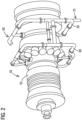
- Fig. 2 illustrates a perspective view of a gas turbine engine 50.
- Piping 60 is attached to the outer casing 55 for the purpose of bleeding cooling air from the compressor section and directing it to the vanes in the turbine section of the engine for cooling purposes.
- compressor debris in the form of oxidation and airborne particulates may also exist in the cooling air flow which may clog the cooling holes 40 of the vanes.
- a dead leg extractor 70,80 may be installed on the existing piping 60 attached to the outer casing 55 of the turbine engine.
- FIG. 3 illustrates the dead leg extractor 70 in a vertical orientation
- Fig. 4 illustrates a horizontal orientation of the dead leg extractor 80.
- the embodiments shown include design features that enhance the amount and type of debris captured by the dead leg extractor 70, 80 while retaining the debris and preventing their escape back into the flow stream. Additionally, the embodiments allow for online removal or purging of the debris from the dead leg to permit the turbine 50 to be operated continuously without having to be shut down for dead leg cleaning.
- a cooling flow flows vertically through the piping 60 within an inlet pipe 61 until it reaches a piping junction 65.
- the cooling air continues to flow within the piping 60 through an outlet pipe 63, as shown by the arrows.
- Debris, having a higher density than the cooling air flow, by inertia, is projected into a dead leg extractor 70.
- the dead leg extractor 70 may comprise a dead leg 69, which may be a vertical extension of the inlet pipe 61 from the junction 65 as shown, and a ringed pipe segment 67.
- the ringed pipe segment 67 is a cone.
- the cone 67 in the dead leg extractor 70, 80 functions as a means to capture and retain the debris that enters the dead leg 69.
- the incorporation of a cone geometry in the dead leg 69 has been shown through laboratory testing to significantly reduce the amount of debris lost over time once captured in the dead leg 69, especially micron sized debris.
- the cone 67 includes a first opening through which a flow containing debris enters, a smaller second opening through which the flow exits and a height.
- An outer diameter of the cone 67 at the first opening may abut an inner diameter of the dead leg pipe 69 such that the entire flow enters the first opening.
- the height of the cone lies in a range of 8.5 to 16.5 x2,54cm.
- the second opening of the cone lies in a range of 4 to 6 x2,54cm. While some ranges have been given, it should be appreciated that other cone geometries may be used depending on the flow characteristics and piping characteristics involved in the implementation.
- the system may include a cutback feature 72. Testing has shown that approximately 10% of the debris would impinge on the corner of the joint at the junction 65 and flow downstream into the outlet pipe 63 with the cooling flow without such a cutback feature. With a cutback feature 72, the debris is more likely to enter the dead leg 69 instead.
- the cutback feature 72 may comprise angling the pipe at the lower portion of the joint so that debris is drawn down into the dead leg 69.
- the system may include the incorporation of a blow down valve 74 connected at an end of the dead leg 70, 80 opposite the junction 65.
- the blow down valve 74 may open periodically on a timer in order to blow out debris.
- the blow down valve 74 allows the dead leg 69 to be purged of debris (due to the positive internal pressure) while the system is operating.
- the purged debris may be disposed into a solid waste container, for example. No shut down would be required to clean the dead leg 69, as would be case with a traditional filter application such as the witch hat implementation.
- the pipe geometry may be optimized for both vertically and horizontally oriented dead legs 70, 80 to maximize debris capture and retention.
- a horizontal portion of the dead leg containing the cone 67 may have a slight downward slope ending in an elbow that flows into a vertically oriented portion of the dead leg 69.
- a blow down valve 74 may be disposed at the end of the vertically oriented portion. The slight downward slope allows gravity to prevent debris from accumulating underneath the cone 67, instead drawing it towards the blow down valve 74. In an embodiment, the slight downward slope lies in a range of 5-15 degrees.
- the proposed system and method reduces the risk of downstream damage, particularly to vanes of a gas turbine, in a turbine system.
- the proposed dead leg extractor can be implemented quickly, causes little if any decrease in cooling flow, carries low risk, takes up little piping space and requires little if any maintenance.
- the dead leg extractor may simply be installed onto the existing piping of a gas turbine engine as shown in the Fig. 2 .
- the dead leg extractor is further relatively inexpensive to manufacture and provides a simple solution that may be installed on newly manufactured turbines as well as already existing turbines.
Landscapes
- Engineering & Computer Science (AREA)
- Mechanical Engineering (AREA)
- General Engineering & Computer Science (AREA)
- Chemical & Material Sciences (AREA)
- Combustion & Propulsion (AREA)
- Turbine Rotor Nozzle Sealing (AREA)
Description
- This application claims the benefit of
U.S. Application No. 62/620,738, filed on January 23, 2018 U.S. Application No. 62/554,839, filed on September 6, 2017 - The present invention is directed, in general, to removing debris from a flow path, and more particularly, to a system and method for removing debris from the flow path of components having cooling holes.
- Debris in the form of scaling oxidation can make its way inside turbine airfoils and clog the cooling holes. Clogged cooling holes may result in overheating and breaching of the airfoils, particularly the row two turbine vanes, requiring a forced outage to replace or repair the vanes.
- In one approach, an in-line witch hat strainer may be used, which is located inside the cooling air pipes leading to the row two vanes. However, such a strainer may cause an undesirable pressure drop, may clog, and may only be cleaned or inspected by shutting down the unit and removing the section of pipe containing it.
- Another approach may include using an in-line cyclonic separator. However, such a separator may need to be tuned for each specific application, is relatively expensive, and may require a significant amount of pipe space compared to other approaches described herein.
- Thus, systems to limit or eliminate such clogging are desirable.
-
US 2011/067409A1 discloses a cooled turbine blade with a centrifugal particle separator wherein cooling flow is communicated to cooling holes via piping that includes a dead leg debris extractor, wherein the dead leg debris extractor includes a means to capture and retain debris from the cooling flow continuously during online operation of the turbine. According toUS 2011/067409 A1 , in operation, the mixture of cooling air and microscopic dust particles enters through the inlet port. The mixture enters the centrifugal particle separator with a particular velocity that arises because of a pressure differential in the cooling network. The rotation creates a centrifugal force, slinging microscopic dust particles within the air flow away from the central axis. The microscopic dust particles migrate toward the conical section while the filtered air exits the centrifugal particle separator through the outlet tube.US 2011/067409 A1 further discloses a conical section arranged proximate to the first end of the centrifugal particle separator. The conical section tapers to a narrow exit portion, where a portion of air and filtered microscopic dust particles exit the centrifugal particle separator. -
EP 3106618A1 discloses a cooling system for a turbine blade comprising a particle collection chamber. The inertia of particulate carries the particulate into particle collection chamber where it is collected and prevented from entering the smaller cross-sectional area metering passage as pressurized air makes a sharp turn into metering passage. - Briefly described, aspects of the present disclosure relate to a system and a method for removing debris from a flow path of a cooling flow. The aspects are met by the independent claims. Preferred embodiments are disclosed in the dependent claims
- The system removes debris from a flow path of a cooling flow. The system includes at least one airfoil to which a cooling flow is communicated, the cooling flow flowing through the cooling holes in the airfoil to cool the airfoil. The cooling flow is communicated to the cooling holes through piping that includes a dead leg debris extractor. The dead leg debris extractor includes a means to capture and retain debris from the cooling flow continuously during online operation of the turbine.
- The method removes debris from a cooling flow communicated to cooling holes of an airfoil in a turbine. The method includes installing a dead leg extractor to piping communicating the cooling flow to the cooling holes of the airfoil and extracting debris from the cooling flow via the dead leg extractor continuously during operation of the turbine.
-
-
Fig. 1 illustrates a perspective view of a turbine vane assembly including cooling holes in the vane, -
Fig. 2 includes a perspective view of a turbine engine outer casing with piping that includes a dead leg extractor, -
Fig. 3 includes a cross sectional view of a dead leg extractor in a vertical orientation, -
Fig. 4 includes a cross sectional view of a dead leg extractor in a horizontal orientation. - Piping dead legs are commonly used in different industrial applications to remove debris or other unwanted substances from a flow path. Typically, the dead leg device is placed on the end of a 90° pipe turn and captures substances which have a higher density than the flow medium by simple inertia. However, dead leg devices typically accumulate debris over time and must be periodically cleaned out while the operating device is offline.
- The following describes a further approach to collect such debris, in which a piping dead leg is used to remove and retain debris from a cooling flow path of a turbine engine. Such a dead leg extractor may be placed as described above at the end of a 90°pipe turn and includes features that will capture and retain almost all the debris in the cooling flow path over time. Additionally, the dead leg extractor allows for periodic removal of the retained debris while the turbine is in on-line operation. While a turbine engine and its corresponding vanes and blades are used throughout the disclosure to exemplify the proposed debris extractor, one skilled in the art would understand that the debris extractor may be utilized to remove debris en route via piping to components further downstream and in particular components including holes through which a fluid flows.
- To facilitate an understanding of embodiments, principles, and features of the present disclosure, they are explained hereinafter with reference to implementation in illustrative embodiments. Embodiments of the present disclosure, however, are not limited to use in the described systems or methods.
- The components and materials described hereinafter as making up the various embodiments are intended to be illustrative and not restrictive. Many suitable components and materials that would perform the same or a similar function as the materials described herein are intended to be embraced within the scope of embodiments of the present disclosure.
- Broadly, a system and method for removing debris from a flow path of a cooling flow is proposed. The system includes a turbine having at least one airfoil via which a cooling flow is communicated to cooling holes in the airfoil via piping that includes a dead leg debris extractor. The dead leg debris extractor comprises a dead leg and a cone within the dead leg. The method includes installing the dead leg extractor to the piping communicating the cooling flow to the cooling holes of the airfoil and, during operation of the turbine continuously extracting debris from the cooling flow via the dead leg extractor.
- Referring now to the
Figures 1 --4, a turbine component for a gas turbine engine is shown inFig. 1 in the form of astationary turbine vane 10. Thevane 10 includes an elongated airfoil having abody 15 with anouter wall 20 and an inner wall. Thevane 10 may also include anouter shroud 25 at a first end of thevane 10 and aninner shroud 30, also known as a platform, at a second end of thevane 10. Thevane 10 may be configured for use in a gas turbine engine. Thebody 15 of the vane may define one or morehollow pockets 35 to allow for a cooling fluid to flow therethrough for cooling of thevane 10. The temperatures to which blades and vanes of a gas turbine are exposed due to the flow of hot gas may be upwards of 450° C and possibly even as high as 1400-1600° C in the flow path. The more efficiently that heat is removed from the component, the higher the overall efficiency that can be achieved. For this purpose, thevane 10 may additionally include a plurality ofcooling holes 40 which are used to cool the internal wall of thevane 10. Extending spanwise within the hollow pockets, thevane 10 may includevane inserts 45 having cooling holes for further cooling. -
Fig. 2 illustrates a perspective view of agas turbine engine 50.Piping 60 is attached to theouter casing 55 for the purpose of bleeding cooling air from the compressor section and directing it to the vanes in the turbine section of the engine for cooling purposes. However, as mentioned above, compressor debris in the form of oxidation and airborne particulates, for example, may also exist in the cooling air flow which may clog the cooling holes 40 of the vanes. In order to remove and retain this debris, adead leg extractor piping 60 attached to theouter casing 55 of the turbine engine. - Referring now to
Figs. 3 and 4 , cross sectional views of embodiments of thedead leg extractor Fig. 3 illustrates thedead leg extractor 70 in a vertical orientation andFig. 4 illustrates a horizontal orientation of thedead leg extractor 80. The embodiments shown include design features that enhance the amount and type of debris captured by thedead leg extractor turbine 50 to be operated continuously without having to be shut down for dead leg cleaning. - For example, in the vertical embodiment as shown in
Figure 3 , a cooling flow (as shown by the arrows) flows vertically through the piping 60 within aninlet pipe 61 until it reaches a pipingjunction 65. At thisjunction 65, the cooling air continues to flow within the piping 60 through anoutlet pipe 63, as shown by the arrows. Debris, having a higher density than the cooling air flow, by inertia, is projected into adead leg extractor 70. As illustrated inFig. 3 , thedead leg extractor 70 may comprise adead leg 69, which may be a vertical extension of theinlet pipe 61 from thejunction 65 as shown, and a ringedpipe segment 67. In an embodiment, as shown inFig. 3 , the ringedpipe segment 67 is a cone. - In an embodiment, the
cone 67 in thedead leg extractor dead leg 69. The incorporation of a cone geometry in thedead leg 69 has been shown through laboratory testing to significantly reduce the amount of debris lost over time once captured in thedead leg 69, especially micron sized debris. In an embodiment, thecone 67 includes a first opening through which a flow containing debris enters, a smaller second opening through which the flow exits and a height. An outer diameter of thecone 67 at the first opening may abut an inner diameter of thedead leg pipe 69 such that the entire flow enters the first opening. In an embodiment, the height of the cone lies in a range of 8.5 to 16.5 x2,54cm. In another embodiment, the second opening of the cone lies in a range of 4 to 6 x2,54cm. While some ranges have been given, it should be appreciated that other cone geometries may be used depending on the flow characteristics and piping characteristics involved in the implementation. - In an embodiment, the system may include a
cutback feature 72. Testing has shown that approximately 10% of the debris would impinge on the corner of the joint at thejunction 65 and flow downstream into theoutlet pipe 63 with the cooling flow without such a cutback feature. With acutback feature 72, the debris is more likely to enter thedead leg 69 instead. Thecutback feature 72 may comprise angling the pipe at the lower portion of the joint so that debris is drawn down into thedead leg 69. - In an embodiment, the system may include the incorporation of a blow down
valve 74 connected at an end of thedead leg junction 65. The blow downvalve 74 may open periodically on a timer in order to blow out debris. The blow downvalve 74 allows thedead leg 69 to be purged of debris (due to the positive internal pressure) while the system is operating. The purged debris may be disposed into a solid waste container, for example. No shut down would be required to clean thedead leg 69, as would be case with a traditional filter application such as the witch hat implementation. - In the illustrated embodiments shown in
Figs. 3 and 4 , the pipe geometry may be optimized for both vertically and horizontally orienteddead legs dead leg extractor 80, a horizontal portion of the dead leg containing thecone 67 may have a slight downward slope ending in an elbow that flows into a vertically oriented portion of thedead leg 69. A blow downvalve 74 may be disposed at the end of the vertically oriented portion. The slight downward slope allows gravity to prevent debris from accumulating underneath thecone 67, instead drawing it towards the blow downvalve 74. In an embodiment, the slight downward slope lies in a range of 5-15 degrees. - The proposed system and method reduces the risk of downstream damage, particularly to vanes of a gas turbine, in a turbine system. Advantageously, the proposed dead leg extractor can be implemented quickly, causes little if any decrease in cooling flow, carries low risk, takes up little piping space and requires little if any maintenance. For example, the dead leg extractor may simply be installed onto the existing piping of a gas turbine engine as shown in the
Fig. 2 . The dead leg extractor is further relatively inexpensive to manufacture and provides a simple solution that may be installed on newly manufactured turbines as well as already existing turbines. - While embodiments of the present disclosure have been disclosed in exemplary forms, it will be apparent to those skilled in the art that many modifications, additions, and deletions can be made therein without departing from the scope of the invention, as set forth in the following claims.
Claims (8)
- A system for removing debris from a flow path of a cooling flow, comprising:a turbine (50) including at least one airfoil (10) to which a cooling flow is communicated, the cooling flow flowing through the cooling holes (40) in the airfoil (10) to cool the airfoil (10), wherein the cooling flow is communicated to the cooling holes (40) via piping (60) that includes an inlet pipe (61), an outlet pipe (63), a junction (65) between the inlet pipe (61) and the outlet pipe (63) and dead leg debris extractor (70, 80), dead leg debris extractor (70, 80) comprising a dead leg (69) being an extension of the inlet pipe (61) from the junction (65),wherein the dead leg debris extractor (70, 80) includes a means to capture and retain debris from the cooling flow continuously during online operation of the turbine (50),characterized in thatthe dead leg debris extractor (70, 80) further comprises a cone (67) within the dead leg (69) as the means to capture and retain debris and a blow down valve (74) connected at an end of the dead leg (70, 8) opposite the junction (65),wherein in case the cooling flow flows vertically within the inlet pipe (61) the dead leg is a vertical extension of the inlet pipe (61),wherein in case the cooling flow flows horizontally within the inlet pipe (61) the dead leg is a horizontal extension of the inlet pipe (61) and includes a portion with a slight downward slope containing the cone (67) connected to a vertical portion containing the blow down valve (74), andwherein the blow down valve (74) may open periodically on a timer in order to blow out debris.
- The system as claimed in claim 1, wherein the cone (67) includes a first opening through which the cooling flow enters, a smaller, second opening through which the cooling flow exits, and a height,wherein an outer diameter of the cone (67) at the first opening abuts an inner diameter of the dead leg extractor (70, 80) such that the entire cooling flow enters the first opening, andwherein the cone (67) captures debris from the cooling flow and retains the debris in the dead leg (69).
- The system as claimed in claim 2, wherein the height of the cone 67 is in a range of 8.5 x 2,54 cm to 16.5 x 2,54 cm.
- The system as claimed in claim 2 or 3, wherein the diameter of the second opening is in a range of 4-6 x 2,54 cm.
- The system as claimed in any of claim 1 to 4, wherein the dead leg extractor (70, 80) includes a cutback (72) at the junction (65) between the inlet pipe 61 and the outlet pipe (63).
- The system as claimed in claim 1, wherein the slight downward slope lies in a range of 5-15 degrees.
- The system as claimed in any of claims 1 to 6, wherein the airfoil is a turbine vane (10).
- A method of removing debris from a cooling flow communicated to cooling holes (40) of an airfoil (10) in a turbine (50), comprising:installing a system as claimed in any of claims 1 to 7,extracting debris from the cooling flow via the dead leg extractor (70, 80) continuously during operation of the turbine (50), and. cleaning out debris in the dead leg (69) by periodically opening the blow down valve 74 automatically on a timer via a controller.
Applications Claiming Priority (3)
| Application Number | Priority Date | Filing Date | Title |
|---|---|---|---|
| US201762554839P | 2017-09-06 | 2017-09-06 | |
| US201862620738P | 2018-01-23 | 2018-01-23 | |
| PCT/US2018/049449 WO2019050879A1 (en) | 2017-09-06 | 2018-09-05 | Dead leg debris extractor for continuous on-line operation |
Publications (2)
| Publication Number | Publication Date |
|---|---|
| EP3679227A1 EP3679227A1 (en) | 2020-07-15 |
| EP3679227B1 true EP3679227B1 (en) | 2024-11-27 |
Family
ID=63678694
Family Applications (1)
| Application Number | Title | Priority Date | Filing Date |
|---|---|---|---|
| EP18773917.2A Active EP3679227B1 (en) | 2017-09-06 | 2018-09-05 | Dead leg debris extractor for continuous on-line operation |
Country Status (3)
| Country | Link |
|---|---|
| US (1) | US10920608B2 (en) |
| EP (1) | EP3679227B1 (en) |
| WO (1) | WO2019050879A1 (en) |
Family Cites Families (14)
| Publication number | Priority date | Publication date | Assignee | Title |
|---|---|---|---|---|
| US2806551A (en) * | 1951-10-16 | 1957-09-17 | Oswald X Heinrich | Centrifugal dust collector with laminar gas flow |
| US5039317A (en) * | 1990-07-05 | 1991-08-13 | Allied-Signal Inc. | Radial inflow particle separation method and apparatus |
| NO318709B1 (en) * | 2000-12-22 | 2005-05-02 | Statoil Asa | Device for separating a liquid from a multiphase fluid stream |
| ES2308081T3 (en) * | 2004-09-22 | 2008-12-01 | Siemens Aktiengesellschaft | REFRIGERATION SYSTEM FOR A GAS TURBINE AND PROCEDURE TO REFRIGERATE A GAS TURBINE. |
| CN101415907A (en) * | 2006-03-31 | 2009-04-22 | 阿尔斯托姆科技有限公司 | Steam turbine installation and associated operating method |
| US8176720B2 (en) | 2009-09-22 | 2012-05-15 | Siemens Energy, Inc. | Air cooled turbine component having an internal filtration system |
| JP5683336B2 (en) * | 2011-03-14 | 2015-03-11 | 三菱重工業株式会社 | gas turbine |
| US20130145747A1 (en) * | 2011-12-07 | 2013-06-13 | Illinois Valley Holding Company | Particulate trap regeneration |
| US8876961B2 (en) * | 2012-02-21 | 2014-11-04 | Mann+Hummel Gmbh | Particle separator with deflector and lateral opening and air filter system |
| US9874126B2 (en) * | 2012-08-08 | 2018-01-23 | Illinois Valley Holding Company | Non-thermal particulate filter regeneration |
| JP6021540B2 (en) * | 2012-09-12 | 2016-11-09 | 三菱日立パワーシステムズ株式会社 | Collection device and gas turbine plant equipped with the same |
| US9897006B2 (en) * | 2015-06-15 | 2018-02-20 | General Electric Company | Hot gas path component cooling system having a particle collection chamber |
| US10563579B2 (en) * | 2015-11-18 | 2020-02-18 | Rolls-Royce North American Technologies Inc. | Air-inlet duct having a particle separator and an agglomerator for a gas turbine engine |
| US10294823B2 (en) * | 2016-05-23 | 2019-05-21 | United Technologies Corporation | Dirt evacuation devices |
-
2018
- 2018-09-05 WO PCT/US2018/049449 patent/WO2019050879A1/en not_active Ceased
- 2018-09-05 EP EP18773917.2A patent/EP3679227B1/en active Active
- 2018-09-05 US US16/644,694 patent/US10920608B2/en active Active
Also Published As
| Publication number | Publication date |
|---|---|
| US10920608B2 (en) | 2021-02-16 |
| EP3679227A1 (en) | 2020-07-15 |
| US20200291814A1 (en) | 2020-09-17 |
| WO2019050879A1 (en) | 2019-03-14 |
Similar Documents
| Publication | Publication Date | Title |
|---|---|---|
| JP6537190B2 (en) | Filter chamber for gas turbine and maintenance method thereof | |
| CN102655925B (en) | Droplet catcher for centrifugal compressor | |
| US10322621B2 (en) | Inertial particle separator for air cycle machine | |
| CN204877682U (en) | A turbine that is used for piece scavenge system and correspondence of turbine | |
| US8146445B2 (en) | Extractive probe for hot flue gas and process measurement | |
| US5558496A (en) | Removing particles from gas turbine coolant | |
| CN110139976B (en) | Particulate separator assembly for a turbine engine | |
| EP1760260A2 (en) | Dirt separator for gas turbine air supply and gas turbine with such a dirt separator | |
| CN110319055A (en) | A kind of impeller of oil smoke separation blower | |
| CN104028052A (en) | Air purification device | |
| US11511222B2 (en) | Anti-contamination baffle for cooling air systems | |
| EP3679227B1 (en) | Dead leg debris extractor for continuous on-line operation | |
| CN209005397U (en) | A spiral expanding dust collector | |
| RU2226121C1 (en) | Inertial gas purifier | |
| JPH09323013A (en) | High-temperature gas dedusting equipment | |
| CN111686519B (en) | Cyclone dust removal device | |
| JP2020512556A (en) | Nozzle of water supply sparger in nuclear reactor and its usage | |
| CN113217901A (en) | Particulate matter clearing device | |
| CN209392890U (en) | A kind of high temperature fume dust removal device | |
| CN107716481B (en) | Supercritical carbon dioxide system boiler blowing device and method | |
| KR101647261B1 (en) | Debris removal device of a gas turbine | |
| CN219454152U (en) | Wind direction diversion type industrial ventilator | |
| JP4051013B2 (en) | Oil eliminator and oil separation and recovery device | |
| JPS60166702A (en) | Contamination detecting device for gas turbine compressor blades | |
| JPH0714450B2 (en) | Dust collector |
Legal Events
| Date | Code | Title | Description |
|---|---|---|---|
| STAA | Information on the status of an ep patent application or granted ep patent |
Free format text: STATUS: UNKNOWN |
|
| STAA | Information on the status of an ep patent application or granted ep patent |
Free format text: STATUS: THE INTERNATIONAL PUBLICATION HAS BEEN MADE |
|
| PUAI | Public reference made under article 153(3) epc to a published international application that has entered the european phase |
Free format text: ORIGINAL CODE: 0009012 |
|
| STAA | Information on the status of an ep patent application or granted ep patent |
Free format text: STATUS: REQUEST FOR EXAMINATION WAS MADE |
|
| 17P | Request for examination filed |
Effective date: 20200306 |
|
| AK | Designated contracting states |
Kind code of ref document: A1 Designated state(s): AL AT BE BG CH CY CZ DE DK EE ES FI FR GB GR HR HU IE IS IT LI LT LU LV MC MK MT NL NO PL PT RO RS SE SI SK SM TR |
|
| AX | Request for extension of the european patent |
Extension state: BA ME |
|
| DAV | Request for validation of the european patent (deleted) | ||
| DAX | Request for extension of the european patent (deleted) | ||
| STAA | Information on the status of an ep patent application or granted ep patent |
Free format text: STATUS: EXAMINATION IS IN PROGRESS |
|
| 17Q | First examination report despatched |
Effective date: 20210610 |
|
| GRAP | Despatch of communication of intention to grant a patent |
Free format text: ORIGINAL CODE: EPIDOSNIGR1 |
|
| STAA | Information on the status of an ep patent application or granted ep patent |
Free format text: STATUS: GRANT OF PATENT IS INTENDED |
|
| INTG | Intention to grant announced |
Effective date: 20240618 |
|
| GRAS | Grant fee paid |
Free format text: ORIGINAL CODE: EPIDOSNIGR3 |
|
| GRAA | (expected) grant |
Free format text: ORIGINAL CODE: 0009210 |
|
| STAA | Information on the status of an ep patent application or granted ep patent |
Free format text: STATUS: THE PATENT HAS BEEN GRANTED |
|
| AK | Designated contracting states |
Kind code of ref document: B1 Designated state(s): AL AT BE BG CH CY CZ DE DK EE ES FI FR GB GR HR HU IE IS IT LI LT LU LV MC MK MT NL NO PL PT RO RS SE SI SK SM TR |
|
| REG | Reference to a national code |
Ref country code: GB Ref legal event code: FG4D |
|
| REG | Reference to a national code |
Ref country code: CH Ref legal event code: EP |
|
| REG | Reference to a national code |
Ref country code: DE Ref legal event code: R096 Ref document number: 602018077004 Country of ref document: DE |
|
| REG | Reference to a national code |
Ref country code: IE Ref legal event code: FG4D |
|
| REG | Reference to a national code |
Ref country code: LT Ref legal event code: MG9D |
|
| REG | Reference to a national code |
Ref country code: NL Ref legal event code: MP Effective date: 20241127 |
|
| PG25 | Lapsed in a contracting state [announced via postgrant information from national office to epo] |
Ref country code: HR Free format text: LAPSE BECAUSE OF FAILURE TO SUBMIT A TRANSLATION OF THE DESCRIPTION OR TO PAY THE FEE WITHIN THE PRESCRIBED TIME-LIMIT Effective date: 20241127 Ref country code: IS Free format text: LAPSE BECAUSE OF FAILURE TO SUBMIT A TRANSLATION OF THE DESCRIPTION OR TO PAY THE FEE WITHIN THE PRESCRIBED TIME-LIMIT Effective date: 20250327 Ref country code: PT Free format text: LAPSE BECAUSE OF FAILURE TO SUBMIT A TRANSLATION OF THE DESCRIPTION OR TO PAY THE FEE WITHIN THE PRESCRIBED TIME-LIMIT Effective date: 20250327 |
|
| PG25 | Lapsed in a contracting state [announced via postgrant information from national office to epo] |
Ref country code: FI Free format text: LAPSE BECAUSE OF FAILURE TO SUBMIT A TRANSLATION OF THE DESCRIPTION OR TO PAY THE FEE WITHIN THE PRESCRIBED TIME-LIMIT Effective date: 20241127 Ref country code: NL Free format text: LAPSE BECAUSE OF FAILURE TO SUBMIT A TRANSLATION OF THE DESCRIPTION OR TO PAY THE FEE WITHIN THE PRESCRIBED TIME-LIMIT Effective date: 20241127 |
|
| REG | Reference to a national code |
Ref country code: AT Ref legal event code: MK05 Ref document number: 1745879 Country of ref document: AT Kind code of ref document: T Effective date: 20241127 |
|
| PG25 | Lapsed in a contracting state [announced via postgrant information from national office to epo] |
Ref country code: BG Free format text: LAPSE BECAUSE OF FAILURE TO SUBMIT A TRANSLATION OF THE DESCRIPTION OR TO PAY THE FEE WITHIN THE PRESCRIBED TIME-LIMIT Effective date: 20241127 |
|
| PG25 | Lapsed in a contracting state [announced via postgrant information from national office to epo] |
Ref country code: ES Free format text: LAPSE BECAUSE OF FAILURE TO SUBMIT A TRANSLATION OF THE DESCRIPTION OR TO PAY THE FEE WITHIN THE PRESCRIBED TIME-LIMIT Effective date: 20241127 |
|
| PG25 | Lapsed in a contracting state [announced via postgrant information from national office to epo] |
Ref country code: NO Free format text: LAPSE BECAUSE OF FAILURE TO SUBMIT A TRANSLATION OF THE DESCRIPTION OR TO PAY THE FEE WITHIN THE PRESCRIBED TIME-LIMIT Effective date: 20250227 |
|
| PG25 | Lapsed in a contracting state [announced via postgrant information from national office to epo] |
Ref country code: LV Free format text: LAPSE BECAUSE OF FAILURE TO SUBMIT A TRANSLATION OF THE DESCRIPTION OR TO PAY THE FEE WITHIN THE PRESCRIBED TIME-LIMIT Effective date: 20241127 Ref country code: AT Free format text: LAPSE BECAUSE OF FAILURE TO SUBMIT A TRANSLATION OF THE DESCRIPTION OR TO PAY THE FEE WITHIN THE PRESCRIBED TIME-LIMIT Effective date: 20241127 Ref country code: GR Free format text: LAPSE BECAUSE OF FAILURE TO SUBMIT A TRANSLATION OF THE DESCRIPTION OR TO PAY THE FEE WITHIN THE PRESCRIBED TIME-LIMIT Effective date: 20250228 |
|
| PG25 | Lapsed in a contracting state [announced via postgrant information from national office to epo] |
Ref country code: PL Free format text: LAPSE BECAUSE OF FAILURE TO SUBMIT A TRANSLATION OF THE DESCRIPTION OR TO PAY THE FEE WITHIN THE PRESCRIBED TIME-LIMIT Effective date: 20241127 |
|
| PG25 | Lapsed in a contracting state [announced via postgrant information from national office to epo] |
Ref country code: RS Free format text: LAPSE BECAUSE OF FAILURE TO SUBMIT A TRANSLATION OF THE DESCRIPTION OR TO PAY THE FEE WITHIN THE PRESCRIBED TIME-LIMIT Effective date: 20250227 |
|
| PG25 | Lapsed in a contracting state [announced via postgrant information from national office to epo] |
Ref country code: SM Free format text: LAPSE BECAUSE OF FAILURE TO SUBMIT A TRANSLATION OF THE DESCRIPTION OR TO PAY THE FEE WITHIN THE PRESCRIBED TIME-LIMIT Effective date: 20241127 |
|
| PG25 | Lapsed in a contracting state [announced via postgrant information from national office to epo] |
Ref country code: DK Free format text: LAPSE BECAUSE OF FAILURE TO SUBMIT A TRANSLATION OF THE DESCRIPTION OR TO PAY THE FEE WITHIN THE PRESCRIBED TIME-LIMIT Effective date: 20241127 |
|
| PG25 | Lapsed in a contracting state [announced via postgrant information from national office to epo] |
Ref country code: EE Free format text: LAPSE BECAUSE OF FAILURE TO SUBMIT A TRANSLATION OF THE DESCRIPTION OR TO PAY THE FEE WITHIN THE PRESCRIBED TIME-LIMIT Effective date: 20241127 |
|
| PG25 | Lapsed in a contracting state [announced via postgrant information from national office to epo] |
Ref country code: RO Free format text: LAPSE BECAUSE OF FAILURE TO SUBMIT A TRANSLATION OF THE DESCRIPTION OR TO PAY THE FEE WITHIN THE PRESCRIBED TIME-LIMIT Effective date: 20241127 |
|
| PG25 | Lapsed in a contracting state [announced via postgrant information from national office to epo] |
Ref country code: SK Free format text: LAPSE BECAUSE OF FAILURE TO SUBMIT A TRANSLATION OF THE DESCRIPTION OR TO PAY THE FEE WITHIN THE PRESCRIBED TIME-LIMIT Effective date: 20241127 |
|
| PG25 | Lapsed in a contracting state [announced via postgrant information from national office to epo] |
Ref country code: CZ Free format text: LAPSE BECAUSE OF FAILURE TO SUBMIT A TRANSLATION OF THE DESCRIPTION OR TO PAY THE FEE WITHIN THE PRESCRIBED TIME-LIMIT Effective date: 20241127 |
|
| PG25 | Lapsed in a contracting state [announced via postgrant information from national office to epo] |
Ref country code: IT Free format text: LAPSE BECAUSE OF FAILURE TO SUBMIT A TRANSLATION OF THE DESCRIPTION OR TO PAY THE FEE WITHIN THE PRESCRIBED TIME-LIMIT Effective date: 20241127 |
|
| REG | Reference to a national code |
Ref country code: DE Ref legal event code: R097 Ref document number: 602018077004 Country of ref document: DE |
|
| PG25 | Lapsed in a contracting state [announced via postgrant information from national office to epo] |
Ref country code: SE Free format text: LAPSE BECAUSE OF FAILURE TO SUBMIT A TRANSLATION OF THE DESCRIPTION OR TO PAY THE FEE WITHIN THE PRESCRIBED TIME-LIMIT Effective date: 20241127 |
|
| PLBE | No opposition filed within time limit |
Free format text: ORIGINAL CODE: 0009261 |
|
| STAA | Information on the status of an ep patent application or granted ep patent |
Free format text: STATUS: NO OPPOSITION FILED WITHIN TIME LIMIT |
|
| PGFP | Annual fee paid to national office [announced via postgrant information from national office to epo] |
Ref country code: DE Payment date: 20250926 Year of fee payment: 8 |
|
| 26N | No opposition filed |
Effective date: 20250828 |