EP3678553B1 - Diagnosis of pathologies using infrasonic signatures - Google Patents
Diagnosis of pathologies using infrasonic signatures Download PDFInfo
- Publication number
- EP3678553B1 EP3678553B1 EP18855091.7A EP18855091A EP3678553B1 EP 3678553 B1 EP3678553 B1 EP 3678553B1 EP 18855091 A EP18855091 A EP 18855091A EP 3678553 B1 EP3678553 B1 EP 3678553B1
- Authority
- EP
- European Patent Office
- Prior art keywords
- frequency
- infrasonic
- signal
- energy
- respiratory
- Prior art date
- Legal status (The legal status is an assumption and is not a legal conclusion. Google has not performed a legal analysis and makes no representation as to the accuracy of the status listed.)
- Active
Links
Images




Classifications
-
- H—ELECTRICITY
- H04—ELECTRIC COMMUNICATION TECHNIQUE
- H04R—LOUDSPEAKERS, MICROPHONES, GRAMOPHONE PICK-UPS OR LIKE ACOUSTIC ELECTROMECHANICAL TRANSDUCERS; ELECTRIC HEARING AIDS; PUBLIC ADDRESS SYSTEMS
- H04R1/00—Details of transducers, loudspeakers or microphones
- H04R1/46—Special adaptations for use as contact microphones, e.g. on musical instrument, on stethoscope
-
- A—HUMAN NECESSITIES
- A61—MEDICAL OR VETERINARY SCIENCE; HYGIENE
- A61B—DIAGNOSIS; SURGERY; IDENTIFICATION
- A61B8/00—Diagnosis using ultrasonic, sonic or infrasonic waves
- A61B8/46—Ultrasonic, sonic or infrasonic diagnostic devices with special arrangements for interfacing with the operator or the patient
- A61B8/461—Displaying means of special interest
-
- A—HUMAN NECESSITIES
- A61—MEDICAL OR VETERINARY SCIENCE; HYGIENE
- A61B—DIAGNOSIS; SURGERY; IDENTIFICATION
- A61B5/00—Measuring for diagnostic purposes; Identification of persons
- A61B5/74—Details of notification to user or communication with user or patient; User input means
- A61B5/7405—Details of notification to user or communication with user or patient; User input means using sound
- A61B5/7415—Sound rendering of measured values, e.g. by pitch or volume variation
-
- A—HUMAN NECESSITIES
- A61—MEDICAL OR VETERINARY SCIENCE; HYGIENE
- A61B—DIAGNOSIS; SURGERY; IDENTIFICATION
- A61B7/00—Instruments for auscultation
- A61B7/003—Detecting lung or respiration noise
-
- A—HUMAN NECESSITIES
- A61—MEDICAL OR VETERINARY SCIENCE; HYGIENE
- A61B—DIAGNOSIS; SURGERY; IDENTIFICATION
- A61B7/00—Instruments for auscultation
- A61B7/02—Stethoscopes
- A61B7/04—Electric stethoscopes
-
- A—HUMAN NECESSITIES
- A61—MEDICAL OR VETERINARY SCIENCE; HYGIENE
- A61B—DIAGNOSIS; SURGERY; IDENTIFICATION
- A61B8/00—Diagnosis using ultrasonic, sonic or infrasonic waves
- A61B8/08—Clinical applications
-
- A—HUMAN NECESSITIES
- A61—MEDICAL OR VETERINARY SCIENCE; HYGIENE
- A61B—DIAGNOSIS; SURGERY; IDENTIFICATION
- A61B8/00—Diagnosis using ultrasonic, sonic or infrasonic waves
- A61B8/44—Constructional features of the ultrasonic, sonic or infrasonic diagnostic device
- A61B8/4416—Constructional features of the ultrasonic, sonic or infrasonic diagnostic device related to combined acquisition of different diagnostic modalities, e.g. combination of ultrasound and X-ray acquisitions
-
- A—HUMAN NECESSITIES
- A61—MEDICAL OR VETERINARY SCIENCE; HYGIENE
- A61B—DIAGNOSIS; SURGERY; IDENTIFICATION
- A61B8/00—Diagnosis using ultrasonic, sonic or infrasonic waves
- A61B8/44—Constructional features of the ultrasonic, sonic or infrasonic diagnostic device
- A61B8/4483—Constructional features of the ultrasonic, sonic or infrasonic diagnostic device characterised by features of the ultrasound transducer
-
- A—HUMAN NECESSITIES
- A61—MEDICAL OR VETERINARY SCIENCE; HYGIENE
- A61B—DIAGNOSIS; SURGERY; IDENTIFICATION
- A61B8/00—Diagnosis using ultrasonic, sonic or infrasonic waves
- A61B8/52—Devices using data or image processing specially adapted for diagnosis using ultrasonic, sonic or infrasonic waves
- A61B8/5215—Devices using data or image processing specially adapted for diagnosis using ultrasonic, sonic or infrasonic waves involving processing of medical diagnostic data
- A61B8/5223—Devices using data or image processing specially adapted for diagnosis using ultrasonic, sonic or infrasonic waves involving processing of medical diagnostic data for extracting a diagnostic or physiological parameter from medical diagnostic data
-
- H—ELECTRICITY
- H04—ELECTRIC COMMUNICATION TECHNIQUE
- H04R—LOUDSPEAKERS, MICROPHONES, GRAMOPHONE PICK-UPS OR LIKE ACOUSTIC ELECTROMECHANICAL TRANSDUCERS; ELECTRIC HEARING AIDS; PUBLIC ADDRESS SYSTEMS
- H04R29/00—Monitoring arrangements; Testing arrangements
- H04R29/008—Visual indication of individual signal levels
-
- A—HUMAN NECESSITIES
- A61—MEDICAL OR VETERINARY SCIENCE; HYGIENE
- A61B—DIAGNOSIS; SURGERY; IDENTIFICATION
- A61B5/00—Measuring for diagnostic purposes; Identification of persons
- A61B5/08—Measuring devices for evaluating the respiratory organs
- A61B5/0816—Measuring devices for examining respiratory frequency
-
- A—HUMAN NECESSITIES
- A61—MEDICAL OR VETERINARY SCIENCE; HYGIENE
- A61B—DIAGNOSIS; SURGERY; IDENTIFICATION
- A61B5/00—Measuring for diagnostic purposes; Identification of persons
- A61B5/103—Measuring devices for testing the shape, pattern, colour, size or movement of the body or parts thereof, for diagnostic purposes
- A61B5/11—Measuring movement of the entire body or parts thereof, e.g. head or hand tremor or mobility of a limb
- A61B5/113—Measuring movement of the entire body or parts thereof, e.g. head or hand tremor or mobility of a limb occurring during breathing
-
- A—HUMAN NECESSITIES
- A61—MEDICAL OR VETERINARY SCIENCE; HYGIENE
- A61B—DIAGNOSIS; SURGERY; IDENTIFICATION
- A61B5/00—Measuring for diagnostic purposes; Identification of persons
- A61B5/72—Signal processing specially adapted for physiological signals or for diagnostic purposes
- A61B5/7235—Details of waveform analysis
- A61B5/7246—Details of waveform analysis using correlation, e.g. template matching or determination of similarity
Definitions
- the present invention relates generally to methods, apparatus and software for medical diagnosis, and particularly to techniques for diagnosis of medical conditions based on processing of acoustic signals.
- Auscultation has been a key technique in medical diagnosis for centuries. In auscultation, the medical practitioner listens to the internal sounds of the body, typically using a stethoscope. Auscultation is most commonly performed for the purpose of examining the circulatory and respiratory systems, and thus diagnosing conditions of the heart and lungs in particular. In more recent years, electronic stethoscopes and methods of digital processing of body sounds have become available, in order to enhance and supplement the practitioner's auditory capabilities.
- U.S. Patent 5,853,005 describes an acoustic monitoring system in which a transducer in communication with fluid in a pad is held in close contact against a sound or movement source and monitors acoustic signals transferred into the fluid. The signal pattern is monitored aurally and/or compared to predetermined reference patterns.
- U.S. Patent 6,699,204 describes a device for analyzing auscultation sounds, in particular respiratory sounds.
- the device comprises an input receiving a sound signal sampled in intensity levels each associated with a selected time, and storage means comprising a processing module for evaluating, in cooperation with computing means, a set of transformed intensity levels, each associated with a predetermined sound frequency. It further comprises an output connected to the storage means for delivering each transformed intensity level in correspondence with an associated frequency, and means for representing intensity levels transformed on the basis of frequencies, to obtain a spectral representation of the auscultation sound.
- U.S. Patent Application Publication 2005/0222515 describes methods of analyzing patient's heart, using a cardiovascular sound signature in diagnosis at the early stages of cardiac dysfunctions.
- the invention is said to present cardiovascular sounds in time and frequency while keeping signal resolution equally strong in both directions.
- US9345432 discloses a method of detecting obstructive sleep apnea in a subject.
- the method includes the steps of placing a head of an electronic stethoscope at the subject's suprasternal notch, providing an electrical signal representative of the sounds detected by the head of the electronic stethoscope within a frequency range, determining an obstructive sleep apnea index based on a ratio of the amount of the electrical signal that is associated with a frequency below a cut-off frequency with respect to a total amount of energy associated with the entire frequency range, and identifying the subject as having obstructive sleep apnea if the obstructive sleep apnea index is above a window maximum or below a window minimum.
- WO-A-00/02486 discloses a handheld electronic stethoscope including a graphic display displaying interpretive information indicative of the type, intensity, and timing of heart or respiratory sounds detected by the stethoscope.
- a signal processor in the stethoscope upon input of a complete frame of data from a sensor, a signal processor in the stethoscope performs a frequency domain conversion of the frame, correlates features in the most recently frequency-converted frames with heart or respiratory sounds, derives variables relevant to the heart or respiratory sounds, and stores the variables in display tables together with pointers to pre-stored text strings for real-time display as text messages.
- An audio output may also be included.
- US5301679 discloses a method and system for evaluation of a human disease by recording body sounds for extended periods of time by a microphone placed in contact with the body of the patient and using computer processing of body sound data to provide frequency domain and time domain sound amplitudes.
- a computer reads out a converted measurement of a sound taken by the microphone and places the data on the computer data bus for further processing.
- the method and system provide diagnostic information on diseases, such as certain diseases of the gastro-intestinal tract and the heart, which generate abnormal body sounds and provide assessment of patient progress during treatment of such disease entities.
- Embodiments of the present invention that are described hereinbelow provide methods, apparatus and software for processing and analysis of acoustic signals received from the body.
- a medical device including an acoustic transducer, which is configured to sense infrasonic waves emitted from a body of a living subject with a periodicity determined by a periodic physiological activity and to output an electrical signal in response to the sensed waves.
- At least one speaker is configured to output audible sounds in response to an electrical input.
- Processing circuitry is configured to process the electrical signal so as to generate a frequency-stretched signal in which infrasonic frequency components of the electrical input are shifted to audible frequencies while preserving the periodicity of the periodic physiological activity in the frequency-stretched signal, and to input the frequency-stretched signal to the at least one speaker.
- the processing circuitry is configured to receive and digitize the electrical signal, to transform the digitized signal to a frequency domain, to shift the infrasonic frequency components to the audible frequencies in the frequency domain so as to generate a frequency-shifted transformed signal, and to retransform the frequency-shifted transformed signal to a time domain in order to generate the frequency-stretched signal.
- the processing circuitry is configured to shift the infrasonic frequency components by interpolating the transformed signal by a predefined factor, and to decimate the retransformed signal in the time domain by the predefined factor in order to generate the frequency-stretched signal while preserving the periodicity of the periodic physiological activity.
- the device includes a user interface, which is configured to receive a user input from a user of the device indicative of a desired stretch of the infrasonic frequency components, and the processing circuitry is configured to adjust the predefined factor responsively to the user input.
- the user interface can be configured to select a value of the predefined factor from among a first value for transformation of respiratory sounds and a second value, greater than the first value, for transformation of cardiac sounds.
- the infrasonic frequency components sensed by the acoustic transducer have frequencies extending at least down to 5 Hz
- the processing circuitry is configured to stretch the infrasonic frequency components so that a component at 5 Hz is shifted to a frequency of at least 20 Hz.
- the device includes a case, which contains the acoustic transducer and at least a part of the processing circuitry, and which is configured to be brought into contact with the body of the living subject, wherein the at least one speaker includes earphones extending from the case and configured to configured to output the audible sounds.
- a medical device including an acoustic transducer, which is configured to sense acoustic waves emitted from a body of a living subject in response to a periodic physiological activity and to output an electrical signal in response to the sensed waves.
- Processing circuitry is configured to compute respective autocorrelations of the electrical signal for a plurality of different times within a period of the physiological activity, to transform the respective autocorrelations to a frequency domain, and to render to a display, responsively to the transformed autocorrelations, a graphical representation of a spectral distribution of an energy of the acoustic waves over the period.
- the acoustic waves include an infrasonic component, and the spectral distribution includes the energy at infrasonic frequencies.
- the device includes at least one speaker, which is configured to output audible sounds in response to an electrical input, wherein the processing circuitry is configured to shift the infrasonic component to audible frequencies so as to generate a frequency-stretched signal, and to generate the electrical input to the at least one speaker responsively to the frequency-stretched signal.
- the physiological activity includes respiration
- the graphical representation is indicative of the energy of the acoustic waves due to respiratory activity of the body.
- the device includes a motion sensor and a case, which contains the acoustic transducer and the motion sensor and is configured to be brought into contact with the body of the living subject, wherein the processor is configured to detect a respiratory motion responsively to an output of the motion sensor, and to extract the period of the respiratory activity from the detected respiratory motion.
- the processing circuitry is configured to render to the display the graphical representation including a plot having a frequency axis and a time axis defining a time-frequency plane and presenting a value of the energy at each point in the time-frequency plane.
- a method for medical diagnosis which includes receiving an electrical signal from an acoustic transducer in response to infrasonic waves emitted from a body of a living subject with a periodicity determined by a periodic physiological activity.
- the electrical signal is processed so as to generate a frequency-stretched signal in which infrasonic frequency components of the electrical input are shifted to audible frequencies while preserving the periodicity of the periodic physiological activity in the frequency-stretched signal.
- An electrical input to at least one speaker is generated responsively to the frequency-stretched signal, whereby the at least one speaker outputs audible sounds in response to the electrical input.
- a method for medical diagnosis which includes receiving an electrical signal from an acoustic transducer in response to acoustic waves emitted from a body of a living subject due to a periodic physiological activity. Respective autocorrelations of the electrical signal are computed for a plurality of different times within a period of the physiological activity. The respective autocorrelations are transformed to a frequency domain, and responsively to the transformed autocorrelations, a graphical representation of a spectral distribution of an energy of the acoustic waves over the period is rendered to a display.
- the stethoscope is generally the first tool that the medical practitioner deploys in attempting to diagnose conditions of the circulatory and respiratory systems.
- Stethoscopes that are known in the art, however, including electronic stethoscopes, are limited by the user's auditory capabilities and diagnostic skills. Acoustic vibrations generated by physiological activity contain a wealth of diagnostic information that is not exploited by traditional auscultation.
- Embodiments of the present invention that are described herein address these limitations by applying techniques of digital signal processing to acoustic waves that are emitted from the body of a living subject in response to periodic physiological activities, such as heart motion and respiration.
- These embodiments provide processing circuitry and methods that can be incorporated, for example, into a digital electronic stethoscope, or alternatively used in conjunction with acoustic transducers in other sorts of diagnostic devices and systems (such as those described in the above-mentioned PCT Patent Application PCT/IB2017/050833 ).
- the disclosed embodiments take advantage not only of acoustic waves in the audible range (defined as the range between 20 Hz and 20,000 Hz), but also infrasonic waves, at frequencies below 20 Hz.
- the processing circuitry processes electrical signal output by an acoustic transducer so as to generate a frequency-stretched signal, in which infrasonic frequency components of the electrical input are shifted to audible frequencies.
- the signal frequencies are shifted, however, the periodicity of the periodic physiological activity is preserved in the frequency-stretched signal. Consequently, the heart sounds repeat at the original heart rate, and breath sounds repeat at the original respiratory rate, while the infrasonic components (as well as audible components) are shifted to higher tones in the audible range.
- the processing circuitry inputs the frequency-stretched signal to one or more speakers, such as the earphones of an electronic stethoscope, which output the corresponding audible sounds.
- one or more speakers such as the earphones of an electronic stethoscope, which output the corresponding audible sounds.
- the medical practitioner can use such a device intuitively, as he or she would use a conventional stethoscope, but will be able to hear a wealth of additional sounds (with the expected periodicity) indicative of infrasonic activity.
- the inventors have found that this approach enhances the practitioner's ability to diagnose cardiac and pulmonary pathologies with only a short learning curve.
- the processing circuitry computes and displays acoustic "signatures" based on the electrical signal output by the acoustic transducer. Such signatures may be applied in conjunction with or separately from the frequency-stretching techniques described above. Specifically, to accommodate the periodic nature of the physiological activity, the processing circuitry computes respective autocorrelations of the electrical signal at multiple different times within the period of the physiological activity. The separation between the autocorrelation peaks reflects the period, for example, the respiratory period, while the autocorrelation amplitude reflects the energy content of the signal.
- the processing circuitry transforms the autocorrelation curves to the frequency domain, and renders the transformed autocorrelations in graphical form to a display.
- This display presents a spectral distribution of the energy of the acoustic waves over the period of the physiological activity, showing how the pattern of frequencies (including infrasonic frequencies) changes over the period, for example over the course of a respiratory cycle.
- the inventors have found that certain respiratory pathologies are characterized by distinct spectral patterns, referred to as signatures, some of which are illustrated in the figures that follow.
- the autocorrelation function reflects the actual, natural period of the physiological activity, as opposed to computing signal energy over some other, arbitrary window, the acoustic signature based on the autocorrelation provides a self-consistent, intuitive picture of the activity and associated pathologies.
- Fig. 1 is a schematic pictorial illustration showing the use of a digital stethoscope 20, in accordance with an embodiment of the invention.
- a practitioner 22 brings a head 26 of stethoscope 20 into contact with the body of a patient 24.
- Processing circuitry in head 26 outputs an audio signal via a cable 28 extending from head 26 to one or more speakers, such as earphones 30, which open apart and fit into the practitioner's ears as would the earphones of a conventional stethoscope.
- speakers such as earphones 30, which open apart and fit into the practitioner's ears as would the earphones of a conventional stethoscope.
- head 26 comprises a case 32, which contains an acoustic transducer, such as a suitable microphone 34, which contacts the body of patient 24 and thus senses acoustic waves emitted from the body.
- Microphone 34 may be of any suitable type that is known in the art, for example a piezoelectric sensor, which is sensitive not only to audible frequencies, but also to infrasonic frequencies going down to 5 Hz.
- a user interface such as a touch-sensitive display 36, enables practitioner 22 to control the functions of stethoscope 20 and displays data, such as acoustic signatures of heart and/or breath sounds sensed by microphone 34.
- Fig. 2 is a block diagram that schematically shows functional elements of stethoscope 20, in accordance with an embodiment of the invention.
- the elements shown in Fig. 2 are assumed to be contained inside head 26, within case 32. Alternatively, however, some of these components may be housed in an external processing unit.
- An analog front end 40 performs analog processing functions, including filtering, buffering and amplification of the electrical signals output by microphone 34.
- head 26 also comprises an inertial sensor, such as an integrated circuit accelerometer 41, which measures motion and low-frequency vibrations of head 26.
- Analog front end 40 may then process the signals output by the inertial sensor, as well.
- An analog/digital converter (ADC) 42 digitizes the acoustic and inertial signals.
- a digital preprocessing circuit 44 transforms the digitized signals to the frequency domain, for example by computing a short-time Fourier transform (STFT) over successive time windows of the signals.
- circuit 44 can perform digital filtering functions, such as noise suppression, and "frequency stretching”: shifting infrasonic frequency components to the audible frequency range, as described further hereinbelow. Following these filtering and frequency stretching steps, circuit 44 converts the frequency-domain samples back to the time domain.
- circuit 44 typically comprises digital processing logic, which may be hard-wired or programmable; but alternatively, at least some of the functions of circuit 44 may be carried out on a programmable processor under the control of software or firmware.
- a digital/analog converter (DAC) 46 converts the stream of time-domain samples to analog form.
- An analog output circuit 48 filters and amplifies the analog signal to generate an electrical input to earphones 30.
- a programmable processor 50 receives the stream of samples - in either the time domain or the frequency domain, or both - from digital preprocessing circuit 44.
- Processor 50 is coupled to a memory 52, which typically comprises non-volatile memory, such as flash memory, containing software or firmware to control the operations of processor 50.
- memory 52 typically comprises volatile random-access memory (RAM), which is used by processor 50 to store the digital samples received from circuit 44, as well as processing results.
- RAM volatile random-access memory
- processor 50 can compute acoustic signatures, representing the spectral distribution of the energy of the acoustic waves over the period of the cardiac or respiratory cycle, as described further hereinbelow.
- Processor 50 renders a graphical representation of the acoustic signature to display 36 and/or outputs the signature information via a communication link (not shown).
- processor 50 may receive and carry out user instructions, for example in response to finger gestures on the touch screen of display 36.
- processing circuitry including analog front end 40, ADC 42, digital preprocessing circuit 44, DAC 46, analog output circuit 48, processor 50 and memory 52, are collectively and individually referred to herein as "processing circuitry.” These components are typically implemented in integrated circuits, as are known in the art, which are mounted together on a printed circuit board within case 32. Alternatively, other implementations of these functional components will be apparent to those skilled in the art after reading the present description and are considered to be within the scope of the present invention. Although Fig. 2 shows a certain arrangement of functional blocks for the sake of conceptual clarity, the functions of at least some of these blocks may be combined into a single integrated circuit chip or, alternatively, split among multiple chips.
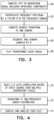
- Fig. 3 is a flow chart that schematically illustrates a method for frequency stretching of infrasonic signals, in accordance with an embodiment of the invention. The method is described here, for the sake of concreteness and clarity, with reference to the components of digital stethoscope 20.
- the object of this method is to generate a frequency-stretched signal in which infrasonic frequency components of the electrical input from microphone 34 are shifted to audible frequencies, while preserving the periodicity of periodic physiological activities (such as heartbeat and/or respiration) in the frequency-stretched signal.
- Digital preprocessing circuit 44 generates the frequency-stretched signal in real time, for output via earphones 30.
- the principles of the method of Fig. 3 may be implemented in substantially any system that includes a suitable acoustic transducer, speaker and processing resources.
- analog front end 40 receives the electrical signal output by microphone 34, and ADC 42 digitizes the signal.
- the time-domain digital samples are input to digital preprocessing circuit 44, which transforms the digitized signal to the frequency domain, using a short-time Fourier transform (STFT), for example.
- STFT short-time Fourier transform
- m and k are both discrete variables (m being the time variable and k being the frequency variable)
- w[n] is a suitable window function, such as a Hamming, Gaussian, or Hann window function.
- circuit 44 interpolates the frequency spectrum F(m,k) in the frequency domain by a factor R in order to yield interpolated spectrum F r (m,k), in which the infrasonic components are shifted to audible frequencies, at an interpolation step 62.
- R may take any rational value, but typical values of R are in the range between 2 and 20, in order to shift infrasonic frequency components to the low end of the audible range. Assuming that the infrasonic frequency components sensed by microphone 34 have frequencies extending at least down to 5 Hz, and circuit 44 will use a value of R such that the infrasonic frequency component at 5 Hz will be shifted to a frequency of at least 20 Hz.
- R Different values of R can be used depending upon whether practitioner 22 wishes to hear respiratory or cardiac sounds.
- practitioner 22 may select the value of R (for example, toggling between preset values for different types of physiological activity) by entering an appropriate user input to stethoscope 20, using the touch screen of display 36, for example.
- digital preprocessing circuit 44 first computes f r [n], the inverse STFT of F r (m,k), at an inverse transformation step 64.
- Circuit 44 then decimates the sequence of time-domain samples f r [n] by the same factor R as was used in interpolation of the frequency spectrum, at a decimation step 65.
- the result is a frequency-stretched signal f s [n], which has the same number of samples, and hence the same periodicity, as the original f[n], but is stretched to higher frequencies.
- DAC 46 converts f s [n] to analog form, and analog output circuit 48 amplifies and inputs this signal to earphones 30, at an audio output step 66.
- the frequency-domain signal F r (m,k) contains the frequency-stretched spectrum in each of a succession of STFT windows.
- the interpolation performed at step 62 can add an incoherent phase offset as a function of frequency between successive windows. Therefore, prior to computing the inverse STFT at step 64, circuit 44 typically rotates the peak phase of each frequency component in each time window in order to match the phase in the preceding time window.
- Fig. 4 is a flow chart that schematically illustrates a method for generating an acoustic signature, in accordance with an embodiment of the invention. As in the preceding embodiment, the method of Fig. 4 is described here, for the sake of concreteness and clarity, with reference to the components of digital stethoscope 20; but this method may alternatively be implemented in substantially any system that includes a suitable acoustic transducer, display and processing resources.
- the method of Fig. 4 makes use of the autocorrelation spectrum of acoustic signals received from microphone 34 over the period of a physiological activity of interest, such as the autocorrelation of heart sounds over the cardiac cycle or breath sounds over the respiratory cycle. For this purpose, it can be useful to extract the period before computing the signature.
- the period can be extracted from the acoustic signals themselves, using methods that are known in the art.
- a motion sensor within case 32 such as accelerometer 41, can be used to sense the respiratory motion of the thorax of patient 24 while head 26 is in contact with the thorax.
- Processor 50 detects the respiratory motion using the output of the motion sensor and thus extracts the period of the patient's respiratory activity.
- Processor 50 identifies significant peaks in the autocorrelation y(k), for example, peaks whose amplitudes exceed a certain threshold and are separated by at least a minimum amount of time, such as 0.5 sec for cardiac activity. The time between each pair of successive peaks is taken to be a candidate period. Processor 50 discards outlying values of the candidate period and averages the remaining values to find the actual period for purposes of computing the acoustic signature.
- a k-nearest neighbor (KNN) approach can be used in classifying successive periods of the autocorrelation function and thus measure the period accurately.
- this method of identifying the time period of the respiratory activity can be used together with an additional sensor, such as a motion sensor to detect the chest motion.
- Fig. 4 the method of Fig. 4 is applied to chest sounds (including infrasonic components) due to respiratory activity, and the resulting acoustic signatures are thus indicative of normal or pathological respiratory patterns.
- processor 50 builds a two-dimensional (2D) autocorrelation matrix based on the digitized samples x(n) of the electrical signals from microphone 34, at a matrix construction step 70.
- processor 50 computes the autocorrelation as a function of a variable time shift I for each time n within a period of the signal.
- Processor 50 transforms the 2D autocorrelation matrix to a matrix representation of the spectral (frequency) distribution of the energy of the acoustic waves over the respiratory period, at a frequency transformation step 72.
- This step can be carried out by calculating a one-dimensional fast Fourier transform (FFT) over the l -dimension of the autocorrelation matrix, which yields the time/frequency chest sounds energy distribution (CSED):
- FFT fast Fourier transform
- N is the number of samples in a respiratory period. Because it is tied to the actual period of respiration, the CSED provides a consistent representation of the spectral distribution of the energy of the acoustic waves, notwithstanding shifts in time and frequency.
- Processor 50 outputs the CSED for used by practitioner 22 and/or further offline recording and analysis, at a CSED output step 74.
- processor 50 may render a graphical representation of the CSED to display 36 or to a separate, external display (not shown).
- This graphical representation comprises a plot having a frequency axis and a time axis, which together define a time-frequency plane. The value of the energy is presented in the plot at each point in the time-frequency plane.
- a number of modes of display of this sort are shown in the figures that follow.
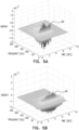
- Figs. 5A-D are plots that schematically illustrate acoustic signatures, in accordance with an embodiment of the invention.
- the time-frequency plane is horizontal, and the energy is represented by peaks extending above and below the plane.
- the time axis is marked in seconds, reflecting the length of an average respiratory period, while the frequency axis is marked in Hertz.
- the energy scale is relative.
- Fig. 5A shows the CSED of normal breath sounds, which is characterized by a sharp ridge 86 of frequencies, in the range of 50-100 Hz, extending continuously in time over the central part of the respiratory cycle.
- Fig. 5B shows a CSED with a wider, more extended ridge 80, reflecting wheezes in the breath sounds of a patient suffering from bronchiectasis due to cystic fibrosis.
- Figs. 5C and 5D illustrate the effect of crackles in the breath sounds of patients with bronchiectasis and pulmonary edema, respectively.
- the crackles are reflected in the CSED by ridges 82 and 84 covering wide ranges of frequencies, repeating multiple times over the course of the respiratory cycle.
- Figs. 6A-D are plots that schematically illustrate acoustic signatures, in accordance with another embodiment of the invention. These plots show the same CSED computations, for the same patients, as in Figs. 5A-D , respectively. In this embodiment, however, the energy as a function of time and frequency is shown as an intensity value, with darker shades of gray corresponding to higher energy values.
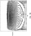
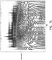
- Figs. 7A-C are plots that schematically illustrate acoustic signatures, in accordance with yet another embodiment of the invention. These plots similarly show energy as an intensity value over the time-frequency plane, except that in this embodiment, the frequency scale is logarithmic.
- Fig. 7A shows the company energy spectrum of a normal patient with healthy lungs.
- Fig. 7B shows the CSED computed over the breath sounds of a patient with chronic obstructive pulmonary disease (COPD), with frequency bands extending down to the infrasonic range over the duration of the respiratory cycle.
- COPD chronic obstructive pulmonary disease
- Fig. 3C shows the CSED of a patient suffering from idiopathic pulmonary fibrosis (IPF), in which crackles are represented by vertical lines in the low-frequency range, again extending down to infrasonic frequencies.
- IPF idiopathic pulmonary fibrosis
Landscapes
- Health & Medical Sciences (AREA)
- Life Sciences & Earth Sciences (AREA)
- Engineering & Computer Science (AREA)
- Physics & Mathematics (AREA)
- General Health & Medical Sciences (AREA)
- Biomedical Technology (AREA)
- Public Health (AREA)
- Animal Behavior & Ethology (AREA)
- Surgery (AREA)
- Molecular Biology (AREA)
- Veterinary Medicine (AREA)
- Medical Informatics (AREA)
- Heart & Thoracic Surgery (AREA)
- Pathology (AREA)
- Biophysics (AREA)
- Acoustics & Sound (AREA)
- Nuclear Medicine, Radiotherapy & Molecular Imaging (AREA)
- Radiology & Medical Imaging (AREA)
- Signal Processing (AREA)
- Computer Vision & Pattern Recognition (AREA)
- Physiology (AREA)
- Otolaryngology (AREA)
- Gynecology & Obstetrics (AREA)
- Pulmonology (AREA)
- Multimedia (AREA)
- Measurement Of The Respiration, Hearing Ability, Form, And Blood Characteristics Of Living Organisms (AREA)
- Measuring Pulse, Heart Rate, Blood Pressure Or Blood Flow (AREA)
Description
- The present invention relates generally to methods, apparatus and software for medical diagnosis, and particularly to techniques for diagnosis of medical conditions based on processing of acoustic signals.
- Auscultation has been a key technique in medical diagnosis for centuries. In auscultation, the medical practitioner listens to the internal sounds of the body, typically using a stethoscope. Auscultation is most commonly performed for the purpose of examining the circulatory and respiratory systems, and thus diagnosing conditions of the heart and lungs in particular. In more recent years, electronic stethoscopes and methods of digital processing of body sounds have become available, in order to enhance and supplement the practitioner's auditory capabilities.
- For example,
U.S. Patent 5,853,005 describes an acoustic monitoring system in which a transducer in communication with fluid in a pad is held in close contact against a sound or movement source and monitors acoustic signals transferred into the fluid. The signal pattern is monitored aurally and/or compared to predetermined reference patterns. - As another example,
U.S. Patent 6,699,204 describes a device for analyzing auscultation sounds, in particular respiratory sounds. The device comprises an input receiving a sound signal sampled in intensity levels each associated with a selected time, and storage means comprising a processing module for evaluating, in cooperation with computing means, a set of transformed intensity levels, each associated with a predetermined sound frequency. It further comprises an output connected to the storage means for delivering each transformed intensity level in correspondence with an associated frequency, and means for representing intensity levels transformed on the basis of frequencies, to obtain a spectral representation of the auscultation sound. -
U.S. Patent Application Publication 2005/0222515 describes methods of analyzing patient's heart, using a cardiovascular sound signature in diagnosis at the early stages of cardiac dysfunctions. The invention is said to present cardiovascular sounds in time and frequency while keeping signal resolution equally strong in both directions. -
US9345432 -
WO-A-00/02486 -
US5301679 discloses a method and system for evaluation of a human disease by recording body sounds for extended periods of time by a microphone placed in contact with the body of the patient and using computer processing of body sound data to provide frequency domain and time domain sound amplitudes. A computer reads out a converted measurement of a sound taken by the microphone and places the data on the computer data bus for further processing. The method and system provide diagnostic information on diseases, such as certain diseases of the gastro-intestinal tract and the heart, which generate abnormal body sounds and provide assessment of patient progress during treatment of such disease entities. - The invention is as defined in the claims.
- Embodiments of the present invention that are described hereinbelow provide methods, apparatus and software for processing and analysis of acoustic signals received from the body.
- There is therefore provided, in accordance with an embodiment of the invention, a medical device, including an acoustic transducer, which is configured to sense infrasonic waves emitted from a body of a living subject with a periodicity determined by a periodic physiological activity and to output an electrical signal in response to the sensed waves. At least one speaker is configured to output audible sounds in response to an electrical input. Processing circuitry is configured to process the electrical signal so as to generate a frequency-stretched signal in which infrasonic frequency components of the electrical input are shifted to audible frequencies while preserving the periodicity of the periodic physiological activity in the frequency-stretched signal, and to input the frequency-stretched signal to the at least one speaker.
- In some embodiments, the processing circuitry is configured to receive and digitize the electrical signal, to transform the digitized signal to a frequency domain, to shift the infrasonic frequency components to the audible frequencies in the frequency domain so as to generate a frequency-shifted transformed signal, and to retransform the frequency-shifted transformed signal to a time domain in order to generate the frequency-stretched signal. In a disclosed embodiment, the processing circuitry is configured to shift the infrasonic frequency components by interpolating the transformed signal by a predefined factor, and to decimate the retransformed signal in the time domain by the predefined factor in order to generate the frequency-stretched signal while preserving the periodicity of the periodic physiological activity.
- In some embodiments, the device includes a user interface, which is configured to receive a user input from a user of the device indicative of a desired stretch of the infrasonic frequency components, and the processing circuitry is configured to adjust the predefined factor responsively to the user input. The user interface can be configured to select a value of the predefined factor from among a first value for transformation of respiratory sounds and a second value, greater than the first value, for transformation of cardiac sounds.
- In a disclosed embodiment, the infrasonic frequency components sensed by the acoustic transducer have frequencies extending at least down to 5 Hz, and the processing circuitry is configured to stretch the infrasonic frequency components so that a component at 5 Hz is shifted to a frequency of at least 20 Hz.
- In one embodiment, the device includes a case, which contains the acoustic transducer and at least a part of the processing circuitry, and which is configured to be brought into contact with the body of the living subject, wherein the at least one speaker includes earphones extending from the case and configured to configured to output the audible sounds.
- There is also provided, in accordance with an embodiment of the invention, a medical device, including an acoustic transducer, which is configured to sense acoustic waves emitted from a body of a living subject in response to a periodic physiological activity and to output an electrical signal in response to the sensed waves. Processing circuitry is configured to compute respective autocorrelations of the electrical signal for a plurality of different times within a period of the physiological activity, to transform the respective autocorrelations to a frequency domain, and to render to a display, responsively to the transformed autocorrelations, a graphical representation of a spectral distribution of an energy of the acoustic waves over the period.
- In some embodiments, the acoustic waves include an infrasonic component, and the spectral distribution includes the energy at infrasonic frequencies. In one embodiment, the device includes at least one speaker, which is configured to output audible sounds in response to an electrical input, wherein the processing circuitry is configured to shift the infrasonic component to audible frequencies so as to generate a frequency-stretched signal, and to generate the electrical input to the at least one speaker responsively to the frequency-stretched signal.
- In some embodiments, the physiological activity includes respiration, and the graphical representation is indicative of the energy of the acoustic waves due to respiratory activity of the body. In a disclosed embodiment, the device includes a motion sensor and a case, which contains the acoustic transducer and the motion sensor and is configured to be brought into contact with the body of the living subject, wherein the processor is configured to detect a respiratory motion responsively to an output of the motion sensor, and to extract the period of the respiratory activity from the detected respiratory motion.
- According to the invention, the processing circuitry is configured to render to the display the graphical representation including a plot having a frequency axis and a time axis defining a time-frequency plane and presenting a value of the energy at each point in the time-frequency plane.
- There is additionally provided, in accordance with an embodiment of the invention, a method for medical diagnosis, which includes receiving an electrical signal from an acoustic transducer in response to infrasonic waves emitted from a body of a living subject with a periodicity determined by a periodic physiological activity. The electrical signal is processed so as to generate a frequency-stretched signal in which infrasonic frequency components of the electrical input are shifted to audible frequencies while preserving the periodicity of the periodic physiological activity in the frequency-stretched signal. An electrical input to at least one speaker is generated responsively to the frequency-stretched signal, whereby the at least one speaker outputs audible sounds in response to the electrical input.
- There is further provided, in accordance with an embodiment of the invention, a method for medical diagnosis, which includes receiving an electrical signal from an acoustic transducer in response to acoustic waves emitted from a body of a living subject due to a periodic physiological activity. Respective autocorrelations of the electrical signal are computed for a plurality of different times within a period of the physiological activity. The respective autocorrelations are transformed to a frequency domain, and responsively to the transformed autocorrelations, a graphical representation of a spectral distribution of an energy of the acoustic waves over the period is rendered to a display.
- The present invention will be more fully understood from the following detailed description of the embodiments thereof, taken together with the drawings in which:
-
-
Fig. 1 is a schematic pictorial illustration showing a digital stethoscope in clinical use, in accordance with an embodiment of the invention; -
Fig. 2 is a block diagram that schematically shows elements of a digital stethoscope, in accordance with an embodiment of the invention; -
Fig. 3 is a flow chart that schematically illustrates a method for frequency stretching of infrasonic signals, in accordance with an embodiment of the invention; -
Fig. 4 is a flow chart that schematically illustrates a method for generating an acoustic signature, in accordance with an embodiment of the invention; -
Figs. 5A-D are plots that schematically illustrate acoustic signatures, in accordance with an embodiment of the invention; -
Figs. 6A-D are plots that schematically illustrate acoustic signatures, in accordance with another embodiment of the invention; and -
Figs. 7A-C are plots that schematically illustrate acoustic signatures, in accordance with yet another embodiment of the invention. - The stethoscope is generally the first tool that the medical practitioner deploys in attempting to diagnose conditions of the circulatory and respiratory systems. Stethoscopes that are known in the art, however, including electronic stethoscopes, are limited by the user's auditory capabilities and diagnostic skills. Acoustic vibrations generated by physiological activity contain a wealth of diagnostic information that is not exploited by traditional auscultation.
- Embodiments of the present invention that are described herein address these limitations by applying techniques of digital signal processing to acoustic waves that are emitted from the body of a living subject in response to periodic physiological activities, such as heart motion and respiration. These embodiments provide processing circuitry and methods that can be incorporated, for example, into a digital electronic stethoscope, or alternatively used in conjunction with acoustic transducers in other sorts of diagnostic devices and systems (such as those described in the above-mentioned PCT Patent Application
PCT/IB2017/050833 ). The disclosed embodiments take advantage not only of acoustic waves in the audible range (defined as the range between 20 Hz and 20,000 Hz), but also infrasonic waves, at frequencies below 20 Hz. - In some embodiments, the processing circuitry processes electrical signal output by an acoustic transducer so as to generate a frequency-stretched signal, in which infrasonic frequency components of the electrical input are shifted to audible frequencies. Although the signal frequencies are shifted, however, the periodicity of the periodic physiological activity is preserved in the frequency-stretched signal. Consequently, the heart sounds repeat at the original heart rate, and breath sounds repeat at the original respiratory rate, while the infrasonic components (as well as audible components) are shifted to higher tones in the audible range.
- The processing circuitry inputs the frequency-stretched signal to one or more speakers, such as the earphones of an electronic stethoscope, which output the corresponding audible sounds. The medical practitioner can use such a device intuitively, as he or she would use a conventional stethoscope, but will be able to hear a wealth of additional sounds (with the expected periodicity) indicative of infrasonic activity. The inventors have found that this approach enhances the practitioner's ability to diagnose cardiac and pulmonary pathologies with only a short learning curve.
- In other embodiments, the processing circuitry computes and displays acoustic "signatures" based on the electrical signal output by the acoustic transducer. Such signatures may be applied in conjunction with or separately from the frequency-stretching techniques described above. Specifically, to accommodate the periodic nature of the physiological activity, the processing circuitry computes respective autocorrelations of the electrical signal at multiple different times within the period of the physiological activity. The separation between the autocorrelation peaks reflects the period, for example, the respiratory period, while the autocorrelation amplitude reflects the energy content of the signal.
- The processing circuitry transforms the autocorrelation curves to the frequency domain, and renders the transformed autocorrelations in graphical form to a display. This display presents a spectral distribution of the energy of the acoustic waves over the period of the physiological activity, showing how the pattern of frequencies (including infrasonic frequencies) changes over the period, for example over the course of a respiratory cycle. The inventors have found that certain respiratory pathologies are characterized by distinct spectral patterns, referred to as signatures, some of which are illustrated in the figures that follow. Because the autocorrelation function reflects the actual, natural period of the physiological activity, as opposed to computing signal energy over some other, arbitrary window, the acoustic signature based on the autocorrelation provides a self-consistent, intuitive picture of the activity and associated pathologies.
-
Fig. 1 is a schematic pictorial illustration showing the use of adigital stethoscope 20, in accordance with an embodiment of the invention. Apractitioner 22 brings ahead 26 ofstethoscope 20 into contact with the body of apatient 24. Processing circuitry inhead 26 outputs an audio signal via acable 28 extending fromhead 26 to one or more speakers, such asearphones 30, which open apart and fit into the practitioner's ears as would the earphones of a conventional stethoscope. - As shown in the inset,
head 26 comprises acase 32, which contains an acoustic transducer, such as asuitable microphone 34, which contacts the body ofpatient 24 and thus senses acoustic waves emitted from the body.Microphone 34 may be of any suitable type that is known in the art, for example a piezoelectric sensor, which is sensitive not only to audible frequencies, but also to infrasonic frequencies going down to 5 Hz. On the other side ofhead 26, a user interface, such as a touch-sensitive display 36, enablespractitioner 22 to control the functions ofstethoscope 20 and displays data, such as acoustic signatures of heart and/or breath sounds sensed bymicrophone 34. -
Fig. 2 is a block diagram that schematically shows functional elements ofstethoscope 20, in accordance with an embodiment of the invention. In the pictured embodiment, the elements shown inFig. 2 are assumed to be contained insidehead 26, withincase 32. Alternatively, however, some of these components may be housed in an external processing unit. - An analog
front end 40 performs analog processing functions, including filtering, buffering and amplification of the electrical signals output bymicrophone 34. Optionally,head 26 also comprises an inertial sensor, such as anintegrated circuit accelerometer 41, which measures motion and low-frequency vibrations ofhead 26. Analogfront end 40 may then process the signals output by the inertial sensor, as well. An analog/digital converter (ADC) 42 digitizes the acoustic and inertial signals. - A
digital preprocessing circuit 44 transforms the digitized signals to the frequency domain, for example by computing a short-time Fourier transform (STFT) over successive time windows of the signals. In addition,circuit 44 can perform digital filtering functions, such as noise suppression, and "frequency stretching": shifting infrasonic frequency components to the audible frequency range, as described further hereinbelow. Following these filtering and frequency stretching steps,circuit 44 converts the frequency-domain samples back to the time domain. For these purposes,circuit 44 typically comprises digital processing logic, which may be hard-wired or programmable; but alternatively, at least some of the functions ofcircuit 44 may be carried out on a programmable processor under the control of software or firmware. A digital/analog converter (DAC) 46 converts the stream of time-domain samples to analog form. Ananalog output circuit 48 filters and amplifies the analog signal to generate an electrical input to earphones 30. - A
programmable processor 50 receives the stream of samples - in either the time domain or the frequency domain, or both - fromdigital preprocessing circuit 44.Processor 50 is coupled to amemory 52, which typically comprises non-volatile memory, such as flash memory, containing software or firmware to control the operations ofprocessor 50. In addition,memory 52 typically comprises volatile random-access memory (RAM), which is used byprocessor 50 to store the digital samples received fromcircuit 44, as well as processing results. - Based on the digitized samples,
processor 50 can compute acoustic signatures, representing the spectral distribution of the energy of the acoustic waves over the period of the cardiac or respiratory cycle, as described further hereinbelow.Processor 50 renders a graphical representation of the acoustic signature to display 36 and/or outputs the signature information via a communication link (not shown). In addition,processor 50 may receive and carry out user instructions, for example in response to finger gestures on the touch screen ofdisplay 36. - The processing components shown
Fig. 2 , including analogfront end 40,ADC 42,digital preprocessing circuit 44,DAC 46,analog output circuit 48,processor 50 andmemory 52, are collectively and individually referred to herein as "processing circuitry." These components are typically implemented in integrated circuits, as are known in the art, which are mounted together on a printed circuit board withincase 32. Alternatively, other implementations of these functional components will be apparent to those skilled in the art after reading the present description and are considered to be within the scope of the present invention. AlthoughFig. 2 shows a certain arrangement of functional blocks for the sake of conceptual clarity, the functions of at least some of these blocks may be combined into a single integrated circuit chip or, alternatively, split among multiple chips. -
Fig. 3 is a flow chart that schematically illustrates a method for frequency stretching of infrasonic signals, in accordance with an embodiment of the invention. The method is described here, for the sake of concreteness and clarity, with reference to the components ofdigital stethoscope 20. As noted earlier, the object of this method is to generate a frequency-stretched signal in which infrasonic frequency components of the electrical input frommicrophone 34 are shifted to audible frequencies, while preserving the periodicity of periodic physiological activities (such as heartbeat and/or respiration) in the frequency-stretched signal.Digital preprocessing circuit 44 generates the frequency-stretched signal in real time, for output viaearphones 30. Alternatively, the principles of the method ofFig. 3 may be implemented in substantially any system that includes a suitable acoustic transducer, speaker and processing resources. - In the method of
Fig. 3 , analogfront end 40 receives the electrical signal output bymicrophone 34, andADC 42 digitizes the signal. The time-domain digital samples are input todigital preprocessing circuit 44, which transforms the digitized signal to the frequency domain, using a short-time Fourier transform (STFT), for example. Formally, the STFT F(m,k) of the time-domain signal f[n], is computed by applying the formula:
- Next,
circuit 44 interpolates the frequency spectrum F(m,k) in the frequency domain by a factor R in order to yield interpolated spectrum Fr(m,k), in which the infrasonic components are shifted to audible frequencies, at aninterpolation step 62. Generally speaking, R may take any rational value, but typical values of R are in the range between 2 and 20, in order to shift infrasonic frequency components to the low end of the audible range. Assuming that the infrasonic frequency components sensed bymicrophone 34 have frequencies extending at least down to 5 Hz, andcircuit 44 will use a value of R such that the infrasonic frequency component at 5 Hz will be shifted to a frequency of at least 20 Hz. - Different values of R can be used depending upon whether
practitioner 22 wishes to hear respiratory or cardiac sounds. For example, respiratory sounds typically fall within the range of 12-2000 Hz, which can be shifted to the audible range of 24-4000 Hz by setting R=2. As another example, heart sounds typically fall within the range of 5-200 Hz, which can be shifted to the audible range of 40-1600 Hz by setting R=8. Optionally,practitioner 22 may select the value of R (for example, toggling between preset values for different types of physiological activity) by entering an appropriate user input tostethoscope 20, using the touch screen ofdisplay 36, for example. - Stretching the frequency content of this acoustic signal, so as to slow down or accelerate the temporal evolution of a sound without altering its time period, requires an explicit separation of temporal and spectral information. As a result of the spectral interpolation performed at
step 62, spectral changes will occur more slowly in the synthesized sound than in the input signal. Simply spacing the frequencies further apart means that phase changes now occur over a longer time interval. Hence, the periodicity of the signal will be inadvertently altered. The solution in the present embodiment is to rescale the phase by precisely the same factor by which the sound is expanded in the frequency domain. This rescaling ensures that the signal in any given filter band has the same frequency variation in the re-synthesis as in the original (though it occurs more slowly), and thus the periodicity of the sounds is preserved. - To carry out the required time domain preservation,
digital preprocessing circuit 44 first computes fr[n], the inverse STFT of Fr(m,k), at aninverse transformation step 64. For this purpose,circuit 44 applies the formula:
Circuit 44 then decimates the sequence of time-domain samples fr[n] by the same factor R as was used in interpolation of the frequency spectrum, at adecimation step 65. The result is a frequency-stretched signal fs[n], which has the same number of samples, and hence the same periodicity, as the original f[n], but is stretched to higher frequencies. (The decimation performed atstep 65 is equivalent to replaying the frequency-shifted sequence of time-domain samples fr[n] at R times the original sample rate.)DAC 46 converts fs[n] to analog form, andanalog output circuit 48 amplifies and inputs this signal toearphones 30, at anaudio output step 66. - The frequency-domain signal Fr(m,k) contains the frequency-stretched spectrum in each of a succession of STFT windows. The interpolation performed at
step 62 can add an incoherent phase offset as a function of frequency between successive windows. Therefore, prior to computing the inverse STFT atstep 64,circuit 44 typically rotates the peak phase of each frequency component in each time window in order to match the phase in the preceding time window. -
Fig. 4 is a flow chart that schematically illustrates a method for generating an acoustic signature, in accordance with an embodiment of the invention. As in the preceding embodiment, the method ofFig. 4 is described here, for the sake of concreteness and clarity, with reference to the components ofdigital stethoscope 20; but this method may alternatively be implemented in substantially any system that includes a suitable acoustic transducer, display and processing resources. - The method of
Fig. 4 makes use of the autocorrelation spectrum of acoustic signals received frommicrophone 34 over the period of a physiological activity of interest, such as the autocorrelation of heart sounds over the cardiac cycle or breath sounds over the respiratory cycle. For this purpose, it can be useful to extract the period before computing the signature. The period can be extracted from the acoustic signals themselves, using methods that are known in the art. Additionally or alternatively, a motion sensor withincase 32, such asaccelerometer 41, can be used to sense the respiratory motion of the thorax ofpatient 24 whilehead 26 is in contact with the thorax.Processor 50 detects the respiratory motion using the output of the motion sensor and thus extracts the period of the patient's respiratory activity. - The period of the activity, based on the digitized signal x(n) from
microphone 34 oraccelerometer 41, can itself be computed using the autocorrelation function:
Processor 50 identifies significant peaks in the autocorrelation y(k), for example, peaks whose amplitudes exceed a certain threshold and are separated by at least a minimum amount of time, such as 0.5 sec for cardiac activity. The time between each pair of successive peaks is taken to be a candidate period.Processor 50 discards outlying values of the candidate period and averages the remaining values to find the actual period for purposes of computing the acoustic signature. Alternatively or additionally, a k-nearest neighbor (KNN) approach can be used in classifying successive periods of the autocorrelation function and thus measure the period accurately. - As noted earlier, this method of identifying the time period of the respiratory activity can be used together with an additional sensor, such as a motion sensor to detect the chest motion.
- In the description that follows, the method of
Fig. 4 is applied to chest sounds (including infrasonic components) due to respiratory activity, and the resulting acoustic signatures are thus indicative of normal or pathological respiratory patterns. In alternative embodiments, not shown in the figures, the principles of this method can be applied, mutatis mutandis, to cardiac activity. To compute the acoustic signature of the respiratory activity,processor 50 builds a two-dimensional (2D) autocorrelation matrix based on the digitized samples x(n) of the electrical signals frommicrophone 34, at amatrix construction step 70. The elements of the autocorrelation matrix y(n,l) have the form:
processor 50 computes the autocorrelation as a function of a variable time shift I for each time n within a period of the signal. -
Processor 50 transforms the 2D autocorrelation matrix to a matrix representation of the spectral (frequency) distribution of the energy of the acoustic waves over the respiratory period, at afrequency transformation step 72. This step can be carried out by calculating a one-dimensional fast Fourier transform (FFT) over the l-dimension of the autocorrelation matrix, which yields the time/frequency chest sounds energy distribution (CSED):
-
Processor 50 outputs the CSED for used bypractitioner 22 and/or further offline recording and analysis, at aCSED output step 74. For example,processor 50 may render a graphical representation of the CSED to display 36 or to a separate, external display (not shown). This graphical representation comprises a plot having a frequency axis and a time axis, which together define a time-frequency plane. The value of the energy is presented in the plot at each point in the time-frequency plane. A number of modes of display of this sort are shown in the figures that follow. -
Figs. 5A-D are plots that schematically illustrate acoustic signatures, in accordance with an embodiment of the invention. In these pseudo-3D plots, the time-frequency plane is horizontal, and the energy is represented by peaks extending above and below the plane. The time axis is marked in seconds, reflecting the length of an average respiratory period, while the frequency axis is marked in Hertz. The energy scale is relative. -
Fig. 5A shows the CSED of normal breath sounds, which is characterized by asharp ridge 86 of frequencies, in the range of 50-100 Hz, extending continuously in time over the central part of the respiratory cycle. By contrast,Fig. 5B shows a CSED with a wider, moreextended ridge 80, reflecting wheezes in the breath sounds of a patient suffering from bronchiectasis due to cystic fibrosis. -
Figs. 5C and 5D illustrate the effect of crackles in the breath sounds of patients with bronchiectasis and pulmonary edema, respectively. The crackles are reflected in the CSED byridges -
Figs. 6A-D are plots that schematically illustrate acoustic signatures, in accordance with another embodiment of the invention. These plots show the same CSED computations, for the same patients, as inFigs. 5A-D , respectively. In this embodiment, however, the energy as a function of time and frequency is shown as an intensity value, with darker shades of gray corresponding to higher energy values. -
Figs. 7A-C are plots that schematically illustrate acoustic signatures, in accordance with yet another embodiment of the invention. These plots similarly show energy as an intensity value over the time-frequency plane, except that in this embodiment, the frequency scale is logarithmic. -
Fig. 7A shows the company energy spectrum of a normal patient with healthy lungs. By contrast,Fig. 7B shows the CSED computed over the breath sounds of a patient with chronic obstructive pulmonary disease (COPD), with frequency bands extending down to the infrasonic range over the duration of the respiratory cycle. As another example, Fig. 3C shows the CSED of a patient suffering from idiopathic pulmonary fibrosis (IPF), in which crackles are represented by vertical lines in the low-frequency range, again extending down to infrasonic frequencies. - The distinctions between normal respiration and various, specific sorts of pathologies are visually apparent in the acoustic signatures shown above. These acoustic signatures can thus assist the practitioner in making fast, accurate diagnoses and assessing changes in the patient's condition thereafter.
- It will be appreciated that the embodiments described above are cited by way of example, and that the present invention is not limited to what has been particularly shown and described hereinabove. Rather, the scope of the present invention includes both combinations and subcombinations of the various features described hereinabove, as well as variations and modifications thereof which would occur to persons skilled in the art upon reading the foregoing description and which are not disclosed in the prior art.
Claims (13)
- A medical device (20), comprising:an acoustic transducer (34), which is configured to sense acoustic waves emitted from a body of a living subject (24) in response to a periodic physiological activity and to output an electrical signal in response to the sensed waves;a display (36); andprocessing circuitry (50), which is configured to compute respective autocorrelations of the electrical signal for a plurality of different times within a period of the physiological activity, to transform the respective autocorrelations to a frequency domain, and to render to the display, responsively to the transformed autocorrelations, a graphical representation of a spectral distribution of an energy of the acoustic waves over the period,wherein the processing circuitry (50), is configured to render to the display the graphical representation comprising a plot having a frequency axis and a time axis defining a time-frequency plane and presenting a value of the energy at each point in the time-frequency plane.
- The device according to claim 1, wherein the acoustic waves comprise an infrasonic component, and wherein the spectral distribution includes the energy at infrasonic frequencies.
- The device according to claim 2, and comprising at least one speaker, which is configured to output audible sounds in response to an electrical input, wherein the processing circuitry is configured to shift the infrasonic component to audible frequencies so as to generate a frequency-stretched signal, and to generate the electrical input to the at least one speaker responsively to the frequency-stretched signal.
- The device according to claim 3, wherein the processing circuitry is configured to receive and digitize the electrical signal, to transform the digitized signal to a frequency domain, to shift the infrasonic frequency components to the audible frequencies in the frequency domain so as to generate a frequency-shifted transformed signal, and to retransform the frequency-shifted transformed signal to a time domain in order to generate the frequency-stretched signal.
- The device according to claim 4, wherein the processing circuitry is configured to shift the infrasonic frequency components by interpolating the transformed signal by a predefined factor, and to decimate the retransformed signal in the time domain by the predefined factor in order to generate the frequency-stretched signal while preserving the periodicity of the periodic physiological activity.
- The device according to claim 5, and comprising a user interface, which is configured to receive a user input from a user of the device indicative of a desired stretch of the infrasonic frequency components, and wherein the processing circuitry is configured to adjust the predefined factor responsively to the user input.
- The device according to claim 6, wherein the user interface is configured to select a value of the predefined factor from among a first value for transformation of respiratory sounds and a second value, greater than the first value, for transformation of cardiac sounds.
- The device according to any of claims 2-7, wherein the infrasonic components sensed by the acoustic transducer have frequencies extending at least down to 5 Hz, and wherein the processing circuitry is configured to stretch the infrasonic frequency components so that a component at 5 Hz is shifted to a frequency of at least 20 Hz.
- The device according to any of claims 1-8, wherein the physiological activity comprises respiration, and wherein the graphical representation is indicative of the energy of the acoustic waves due to respiratory activity of the body.
- The device according to claim 9, and comprising a motion sensor and a case, which contains the acoustic transducer and the motion sensor and is configured to be brought into contact with the body of the living subject, wherein the processor is configured to detect a respiratory motion responsively to an output of the motion sensor, and to extract the period of the respiratory activity from the detected respiratory motion.
- A method for medical diagnosis, comprising:receiving an electrical signal from an acoustic transducer (34) in response to acoustic waves emitted from a body of a living subject (24) due to a periodic physiological activity;computing respective autocorrelations of the electrical signal for a plurality of different times within a period of the physiological activity;transforming the respective autocorrelations to a frequency domain; andrendering to a display (36), responsively to the transformed autocorrelations, a graphical representation of a spectral distribution of an energy of the acoustic waves over the period,wherein the graphical representation comprises a plot having a frequency axis and a time axis defining a time-frequency plane and presenting a value of the energy at each point in the time-frequency plane.
- The method according to claim 11, wherein the acoustic waves comprise an infrasonic component, and wherein the spectral distribution includes the energy at infrasonic frequencies, and comprising stretching the infrasonic component to audible frequencies so as to generate a frequency-stretched signal, and generating an electrical input to at least one speaker responsively to the frequency-stretched signal, whereby the at least one speaker outputs audible sounds in response to the electrical input.
- The method according to claim 11, wherein the physiological activity comprises respiration, and wherein the graphical representation is indicative of the energy of the acoustic waves due to respiratory activity of the body.
Applications Claiming Priority (3)
| Application Number | Priority Date | Filing Date | Title |
|---|---|---|---|
| US201762554041P | 2017-09-05 | 2017-09-05 | |
| US15/953,502 US11116478B2 (en) | 2016-02-17 | 2018-04-16 | Diagnosis of pathologies using infrasonic signatures |
| PCT/IB2018/056336 WO2019048961A1 (en) | 2017-09-05 | 2018-08-22 | Diagnosis of pathologies using infrasonic signatures |
Publications (3)
| Publication Number | Publication Date |
|---|---|
| EP3678553A1 EP3678553A1 (en) | 2020-07-15 |
| EP3678553A4 EP3678553A4 (en) | 2021-05-26 |
| EP3678553B1 true EP3678553B1 (en) | 2024-05-22 |
Family
ID=65633630
Family Applications (2)
| Application Number | Title | Priority Date | Filing Date |
|---|---|---|---|
| EP18855091.7A Active EP3678553B1 (en) | 2017-09-05 | 2018-08-22 | Diagnosis of pathologies using infrasonic signatures |
| EP18853978.7A Active EP3678551B1 (en) | 2017-09-05 | 2018-08-22 | Electronic stethoscope with enhanced features |
Family Applications After (1)
| Application Number | Title | Priority Date | Filing Date |
|---|---|---|---|
| EP18853978.7A Active EP3678551B1 (en) | 2017-09-05 | 2018-08-22 | Electronic stethoscope with enhanced features |
Country Status (3)
| Country | Link |
|---|---|
| US (1) | US20210345991A1 (en) |
| EP (2) | EP3678553B1 (en) |
| WO (2) | WO2019048961A1 (en) |
Families Citing this family (10)
| Publication number | Priority date | Publication date | Assignee | Title |
|---|---|---|---|---|
| ES2688093T3 (en) | 2010-01-06 | 2018-10-30 | Dyax Corp. | Plasma kallikrein binding proteins |
| KR20240049627A (en) | 2014-01-21 | 2024-04-16 | 다케다 파머수티컬 컴패니 리미티드 | Plasma kallikrein binding proteins and uses thereof in treating hereditary angioedema |
| CN110731778B (en) * | 2019-07-22 | 2022-04-29 | 华南师范大学 | Method and system for recognizing breathing sound signal based on visualization |
| CA3167336A1 (en) | 2020-01-13 | 2021-07-22 | Takeda Pharmaceutical Company Limited | Plasma kallikrein inhibitors and uses thereof for treating pediatric hereditary angioedema attack |
| US11240579B2 (en) | 2020-05-08 | 2022-02-01 | Level 42 Ai | Sensor systems and methods for characterizing health conditions |
| WO2022118105A1 (en) * | 2020-12-01 | 2022-06-09 | Sanolla Ltd. | Multi-function diagnostic device |
| US20240008750A1 (en) * | 2020-12-01 | 2024-01-11 | Sanolla Ltd. | Diagnosis of respiratory diseases |
| USD1042851S1 (en) | 2021-06-16 | 2024-09-17 | Sanolla Ltd. | Medical diagnostic device |
| US20240016468A1 (en) * | 2022-07-15 | 2024-01-18 | Globalmedia Group, Llc | Stethoscope systems and assemblies |
| FI131437B1 (en) * | 2022-10-31 | 2025-04-22 | Lapsi Health B V | Chestpiece for stethoscope, electronic stethoscope and use |
Citations (1)
| Publication number | Priority date | Publication date | Assignee | Title |
|---|---|---|---|---|
| US20140073864A1 (en) * | 2012-09-11 | 2014-03-13 | Nellcor Puritan Bennett Llc | Methods and systems for determining physiological information based on fast start parameters |
Family Cites Families (22)
| Publication number | Priority date | Publication date | Assignee | Title |
|---|---|---|---|---|
| US5301679A (en) | 1991-05-31 | 1994-04-12 | Taylor Microtechnology, Inc. | Method and system for analysis of body sounds |
| US5853005A (en) | 1996-05-02 | 1998-12-29 | The United States Of America As Represented By The Secretary Of The Army | Acoustic monitoring system |
| AU4953299A (en) | 1998-07-08 | 2000-02-01 | Cirrus Systems, Llc | Analytic stethoscope |
| FR2791248B1 (en) | 1999-03-24 | 2001-08-24 | Georges Kehyayan | DEVICE FOR ANALYZING AUSCULTATORY NOISE, IN PARTICULAR RESPIRATORY NOISE |
| US20010030077A1 (en) * | 2000-01-10 | 2001-10-18 | Watson Richard L. | Stethoscope with ECG monitor |
| AU2001282440A1 (en) * | 2000-07-31 | 2002-02-13 | Acoustical Diagnostic Ltd | Infrasonic auscultation apparatus |
| IL140148A0 (en) * | 2000-12-07 | 2002-02-10 | Hybrid stethoscope | |
| US20030002685A1 (en) * | 2001-06-27 | 2003-01-02 | Werblud Marc S. | Electronic stethoscope |
| US20050222515A1 (en) | 2004-02-23 | 2005-10-06 | Biosignetics Corporation | Cardiovascular sound signature: method, process and format |
| US7636445B2 (en) * | 2005-05-18 | 2009-12-22 | Takashi Yoshimine | Stethoscope apparatus |
| US8920343B2 (en) * | 2006-03-23 | 2014-12-30 | Michael Edward Sabatino | Apparatus for acquiring and processing of physiological auditory signals |
| US20090316925A1 (en) * | 2008-06-20 | 2009-12-24 | Leonard Eisenfeld | Electronic stethoscope system |
| WO2011082199A1 (en) | 2009-12-29 | 2011-07-07 | The Board Of Governors For Higher Education, State Of Rhode Island And Providence Plantations | Systems for sleep apnea detection from breathing sounds |
| KR20120040530A (en) * | 2010-10-19 | 2012-04-27 | 정보통신산업진흥원 | Patient friendly medical support electronic stethoscope and stethosocopy method using the same |
| US8475396B2 (en) * | 2011-02-11 | 2013-07-02 | AventuSoft, LLC | Method and system of an acoustic scene analyzer for body sounds |
| JP6526049B2 (en) * | 2014-04-09 | 2019-06-05 | エックスモス インコーポレイテッド | Method and system for improved measurements in source signal separation, entity and parameter estimation, and path propagation effect measurement and mitigation |
| GB2534175A (en) * | 2015-01-15 | 2016-07-20 | Buddi Ltd | Ingestion monitoring system |
| US10149635B2 (en) * | 2015-08-14 | 2018-12-11 | Massachusetts Institute Of Technology | Ingestible devices and methods for physiological status monitoring |
| GB201516836D0 (en) | 2015-09-23 | 2015-11-04 | Glaxosmithkline Ip No 2 Ltd | Dosing regimen of combination |
| US11116478B2 (en) * | 2016-02-17 | 2021-09-14 | Sanolla Ltd. | Diagnosis of pathologies using infrasonic signatures |
| EP3692923B1 (en) * | 2016-02-17 | 2022-06-29 | Sanolla Ltd | Digital stethoscopes, and auscultation and imaging systems |
| CN107510473A (en) * | 2017-08-30 | 2017-12-26 | 杨松 | The control method of electronic auscultation device and electronic auscultation device |
-
2018
- 2018-08-22 WO PCT/IB2018/056336 patent/WO2019048961A1/en not_active Ceased
- 2018-08-22 WO PCT/IB2018/056335 patent/WO2019048960A1/en not_active Ceased
- 2018-08-22 EP EP18855091.7A patent/EP3678553B1/en active Active
- 2018-08-22 EP EP18853978.7A patent/EP3678551B1/en active Active
-
2021
- 2021-07-18 US US17/378,710 patent/US20210345991A1/en not_active Abandoned
Patent Citations (1)
| Publication number | Priority date | Publication date | Assignee | Title |
|---|---|---|---|---|
| US20140073864A1 (en) * | 2012-09-11 | 2014-03-13 | Nellcor Puritan Bennett Llc | Methods and systems for determining physiological information based on fast start parameters |
Also Published As
| Publication number | Publication date |
|---|---|
| EP3678551A4 (en) | 2021-05-26 |
| EP3678551B1 (en) | 2023-06-28 |
| EP3678553A4 (en) | 2021-05-26 |
| EP3678551C0 (en) | 2023-06-28 |
| WO2019048961A1 (en) | 2019-03-14 |
| WO2019048960A1 (en) | 2019-03-14 |
| EP3678553A1 (en) | 2020-07-15 |
| EP3678551A1 (en) | 2020-07-15 |
| US20210345991A1 (en) | 2021-11-11 |
Similar Documents
| Publication | Publication Date | Title |
|---|---|---|
| US11116478B2 (en) | Diagnosis of pathologies using infrasonic signatures | |
| US20210345991A1 (en) | Diagnosis of pathologies using infrasonic signatures | |
| EP2624746B1 (en) | Processing of periodic physiological signals | |
| JP5271718B2 (en) | How to identify fetal and maternal ECGs across multiple time segments | |
| US12029606B2 (en) | Electronic stethoscope with enhanced features | |
| JP2007532207A (en) | Non-invasive measurement method for the second heart sound component | |
| WO2008036911A2 (en) | System and method for acoustic detection of coronary artery disease | |
| US20080260173A1 (en) | Method, device and system for cardio-acoustic signal analysis | |
| CN107106118B (en) | Methods of detecting dicrotic notch | |
| JP2022091851A (en) | Detection device | |
| JP6467044B2 (en) | Shunt sound analysis device, shunt sound analysis method, computer program, and recording medium | |
| Orović et al. | Time-frequency analysis and Hermite projection method applied to swallowing accelerometry signals | |
| Vikhe et al. | Wavelet transform based abnormality analysis of heart sound | |
| Talab et al. | Detecting heart anomalies using mobile phones and machine learning | |
| Song et al. | Passive acoustic maternal abdominal fetal heart rate monitoring using wavelet transform | |
| JP6298527B2 (en) | Body sound analysis apparatus, body sound analysis method, computer program, and recording medium | |
| KR20160147591A (en) | Method and apparatus for preprocessing stethoscopic sound signal for diagnosing asthma | |
| EP2014235A1 (en) | Method, device and system for cardio-accoustic signal analysis | |
| Pariaszewska et al. | Digital stethoscope system: the feasibility of cardiac auscultation | |
| Grundlehner et al. | Methods to characterize sensors for capturing body sounds | |
| JP2019111347A (en) | Shunt sound analysis device, shunt sound analysis method, computer program and recording medium | |
| EP4255305A1 (en) | Multi-function diagnostic device | |
| US12178585B2 (en) | Multi sensor and method | |
| Yuqi et al. | Application of the visual auscultatory blood pressure measuring system | |
| RU2380033C1 (en) | Pulse diagnostic technique for atherosclerosis |
Legal Events
| Date | Code | Title | Description |
|---|---|---|---|
| STAA | Information on the status of an ep patent application or granted ep patent |
Free format text: STATUS: THE INTERNATIONAL PUBLICATION HAS BEEN MADE |
|
| PUAI | Public reference made under article 153(3) epc to a published international application that has entered the european phase |
Free format text: ORIGINAL CODE: 0009012 |
|
| STAA | Information on the status of an ep patent application or granted ep patent |
Free format text: STATUS: REQUEST FOR EXAMINATION WAS MADE |
|
| 17P | Request for examination filed |
Effective date: 20200204 |
|
| AK | Designated contracting states |
Kind code of ref document: A1 Designated state(s): AL AT BE BG CH CY CZ DE DK EE ES FI FR GB GR HR HU IE IS IT LI LT LU LV MC MK MT NL NO PL PT RO RS SE SI SK SM TR |
|
| AX | Request for extension of the european patent |
Extension state: BA ME |
|
| DAV | Request for validation of the european patent (deleted) | ||
| DAX | Request for extension of the european patent (deleted) | ||
| RAP1 | Party data changed (applicant data changed or rights of an application transferred) |
Owner name: SANOLLA LTD |
|
| A4 | Supplementary search report drawn up and despatched |
Effective date: 20210422 |
|
| RIC1 | Information provided on ipc code assigned before grant |
Ipc: A61B 7/04 20060101AFI20210416BHEP Ipc: H04R 1/46 20060101ALI20210416BHEP |
|
| STAA | Information on the status of an ep patent application or granted ep patent |
Free format text: STATUS: EXAMINATION IS IN PROGRESS |
|
| 17Q | First examination report despatched |
Effective date: 20230315 |
|
| GRAP | Despatch of communication of intention to grant a patent |
Free format text: ORIGINAL CODE: EPIDOSNIGR1 |
|
| STAA | Information on the status of an ep patent application or granted ep patent |
Free format text: STATUS: GRANT OF PATENT IS INTENDED |
|
| INTG | Intention to grant announced |
Effective date: 20231218 |
|
| GRAS | Grant fee paid |
Free format text: ORIGINAL CODE: EPIDOSNIGR3 |
|
| GRAA | (expected) grant |
Free format text: ORIGINAL CODE: 0009210 |
|
| STAA | Information on the status of an ep patent application or granted ep patent |
Free format text: STATUS: THE PATENT HAS BEEN GRANTED |
|
| AK | Designated contracting states |
Kind code of ref document: B1 Designated state(s): AL AT BE BG CH CY CZ DE DK EE ES FI FR GB GR HR HU IE IS IT LI LT LU LV MC MK MT NL NO PL PT RO RS SE SI SK SM TR |
|
| REG | Reference to a national code |
Ref country code: GB Ref legal event code: FG4D |
|
| P01 | Opt-out of the competence of the unified patent court (upc) registered |
Effective date: 20240419 |
|
| REG | Reference to a national code |
Ref country code: CH Ref legal event code: EP |
|
| REG | Reference to a national code |
Ref country code: DE Ref legal event code: R096 Ref document number: 602018069880 Country of ref document: DE |
|
| REG | Reference to a national code |
Ref country code: IE Ref legal event code: FG4D |
|
| REG | Reference to a national code |
Ref country code: LT Ref legal event code: MG9D |
|
| REG | Reference to a national code |
Ref country code: NL Ref legal event code: MP Effective date: 20240522 |
|
| PG25 | Lapsed in a contracting state [announced via postgrant information from national office to epo] |
Ref country code: IS Free format text: LAPSE BECAUSE OF FAILURE TO SUBMIT A TRANSLATION OF THE DESCRIPTION OR TO PAY THE FEE WITHIN THE PRESCRIBED TIME-LIMIT Effective date: 20240922 |
|
| PG25 | Lapsed in a contracting state [announced via postgrant information from national office to epo] |
Ref country code: BG Free format text: LAPSE BECAUSE OF FAILURE TO SUBMIT A TRANSLATION OF THE DESCRIPTION OR TO PAY THE FEE WITHIN THE PRESCRIBED TIME-LIMIT Effective date: 20240522 |
|
| PG25 | Lapsed in a contracting state [announced via postgrant information from national office to epo] |
Ref country code: HR Free format text: LAPSE BECAUSE OF FAILURE TO SUBMIT A TRANSLATION OF THE DESCRIPTION OR TO PAY THE FEE WITHIN THE PRESCRIBED TIME-LIMIT Effective date: 20240522 Ref country code: FI Free format text: LAPSE BECAUSE OF FAILURE TO SUBMIT A TRANSLATION OF THE DESCRIPTION OR TO PAY THE FEE WITHIN THE PRESCRIBED TIME-LIMIT Effective date: 20240522 |
|
| PG25 | Lapsed in a contracting state [announced via postgrant information from national office to epo] |
Ref country code: GR Free format text: LAPSE BECAUSE OF FAILURE TO SUBMIT A TRANSLATION OF THE DESCRIPTION OR TO PAY THE FEE WITHIN THE PRESCRIBED TIME-LIMIT Effective date: 20240823 |
|
| PG25 | Lapsed in a contracting state [announced via postgrant information from national office to epo] |
Ref country code: PT Free format text: LAPSE BECAUSE OF FAILURE TO SUBMIT A TRANSLATION OF THE DESCRIPTION OR TO PAY THE FEE WITHIN THE PRESCRIBED TIME-LIMIT Effective date: 20240923 |
|
| REG | Reference to a national code |
Ref country code: AT Ref legal event code: MK05 Ref document number: 1688115 Country of ref document: AT Kind code of ref document: T Effective date: 20240522 |
|
| PG25 | Lapsed in a contracting state [announced via postgrant information from national office to epo] |
Ref country code: NL Free format text: LAPSE BECAUSE OF FAILURE TO SUBMIT A TRANSLATION OF THE DESCRIPTION OR TO PAY THE FEE WITHIN THE PRESCRIBED TIME-LIMIT Effective date: 20240522 |
|
| PG25 | Lapsed in a contracting state [announced via postgrant information from national office to epo] |
Ref country code: ES Free format text: LAPSE BECAUSE OF FAILURE TO SUBMIT A TRANSLATION OF THE DESCRIPTION OR TO PAY THE FEE WITHIN THE PRESCRIBED TIME-LIMIT Effective date: 20240522 |
|
| PG25 | Lapsed in a contracting state [announced via postgrant information from national office to epo] |
Ref country code: AT Free format text: LAPSE BECAUSE OF FAILURE TO SUBMIT A TRANSLATION OF THE DESCRIPTION OR TO PAY THE FEE WITHIN THE PRESCRIBED TIME-LIMIT Effective date: 20240522 |
|
| PG25 | Lapsed in a contracting state [announced via postgrant information from national office to epo] |
Ref country code: PL Free format text: LAPSE BECAUSE OF FAILURE TO SUBMIT A TRANSLATION OF THE DESCRIPTION OR TO PAY THE FEE WITHIN THE PRESCRIBED TIME-LIMIT Effective date: 20240522 |
|
| PG25 | Lapsed in a contracting state [announced via postgrant information from national office to epo] |
Ref country code: LV Free format text: LAPSE BECAUSE OF FAILURE TO SUBMIT A TRANSLATION OF THE DESCRIPTION OR TO PAY THE FEE WITHIN THE PRESCRIBED TIME-LIMIT Effective date: 20240522 |
|
| PG25 | Lapsed in a contracting state [announced via postgrant information from national office to epo] |
Ref country code: PT Free format text: LAPSE BECAUSE OF FAILURE TO SUBMIT A TRANSLATION OF THE DESCRIPTION OR TO PAY THE FEE WITHIN THE PRESCRIBED TIME-LIMIT Effective date: 20240923 Ref country code: PL Free format text: LAPSE BECAUSE OF FAILURE TO SUBMIT A TRANSLATION OF THE DESCRIPTION OR TO PAY THE FEE WITHIN THE PRESCRIBED TIME-LIMIT Effective date: 20240522 Ref country code: NO Free format text: LAPSE BECAUSE OF FAILURE TO SUBMIT A TRANSLATION OF THE DESCRIPTION OR TO PAY THE FEE WITHIN THE PRESCRIBED TIME-LIMIT Effective date: 20240822 Ref country code: NL Free format text: LAPSE BECAUSE OF FAILURE TO SUBMIT A TRANSLATION OF THE DESCRIPTION OR TO PAY THE FEE WITHIN THE PRESCRIBED TIME-LIMIT Effective date: 20240522 Ref country code: LV Free format text: LAPSE BECAUSE OF FAILURE TO SUBMIT A TRANSLATION OF THE DESCRIPTION OR TO PAY THE FEE WITHIN THE PRESCRIBED TIME-LIMIT Effective date: 20240522 Ref country code: IS Free format text: LAPSE BECAUSE OF FAILURE TO SUBMIT A TRANSLATION OF THE DESCRIPTION OR TO PAY THE FEE WITHIN THE PRESCRIBED TIME-LIMIT Effective date: 20240922 Ref country code: HR Free format text: LAPSE BECAUSE OF FAILURE TO SUBMIT A TRANSLATION OF THE DESCRIPTION OR TO PAY THE FEE WITHIN THE PRESCRIBED TIME-LIMIT Effective date: 20240522 Ref country code: GR Free format text: LAPSE BECAUSE OF FAILURE TO SUBMIT A TRANSLATION OF THE DESCRIPTION OR TO PAY THE FEE WITHIN THE PRESCRIBED TIME-LIMIT Effective date: 20240823 Ref country code: FI Free format text: LAPSE BECAUSE OF FAILURE TO SUBMIT A TRANSLATION OF THE DESCRIPTION OR TO PAY THE FEE WITHIN THE PRESCRIBED TIME-LIMIT Effective date: 20240522 Ref country code: ES Free format text: LAPSE BECAUSE OF FAILURE TO SUBMIT A TRANSLATION OF THE DESCRIPTION OR TO PAY THE FEE WITHIN THE PRESCRIBED TIME-LIMIT Effective date: 20240522 Ref country code: BG Free format text: LAPSE BECAUSE OF FAILURE TO SUBMIT A TRANSLATION OF THE DESCRIPTION OR TO PAY THE FEE WITHIN THE PRESCRIBED TIME-LIMIT Effective date: 20240522 Ref country code: AT Free format text: LAPSE BECAUSE OF FAILURE TO SUBMIT A TRANSLATION OF THE DESCRIPTION OR TO PAY THE FEE WITHIN THE PRESCRIBED TIME-LIMIT Effective date: 20240522 Ref country code: RS Free format text: LAPSE BECAUSE OF FAILURE TO SUBMIT A TRANSLATION OF THE DESCRIPTION OR TO PAY THE FEE WITHIN THE PRESCRIBED TIME-LIMIT Effective date: 20240822 |
|
| PG25 | Lapsed in a contracting state [announced via postgrant information from national office to epo] |
Ref country code: DK Free format text: LAPSE BECAUSE OF FAILURE TO SUBMIT A TRANSLATION OF THE DESCRIPTION OR TO PAY THE FEE WITHIN THE PRESCRIBED TIME-LIMIT Effective date: 20240522 |
|
| PG25 | Lapsed in a contracting state [announced via postgrant information from national office to epo] |
Ref country code: EE Free format text: LAPSE BECAUSE OF FAILURE TO SUBMIT A TRANSLATION OF THE DESCRIPTION OR TO PAY THE FEE WITHIN THE PRESCRIBED TIME-LIMIT Effective date: 20240522 |
|
| PG25 | Lapsed in a contracting state [announced via postgrant information from national office to epo] |
Ref country code: CZ Free format text: LAPSE BECAUSE OF FAILURE TO SUBMIT A TRANSLATION OF THE DESCRIPTION OR TO PAY THE FEE WITHIN THE PRESCRIBED TIME-LIMIT Effective date: 20240522 |
|
| PG25 | Lapsed in a contracting state [announced via postgrant information from national office to epo] |
Ref country code: SK Free format text: LAPSE BECAUSE OF FAILURE TO SUBMIT A TRANSLATION OF THE DESCRIPTION OR TO PAY THE FEE WITHIN THE PRESCRIBED TIME-LIMIT Effective date: 20240522 Ref country code: RO Free format text: LAPSE BECAUSE OF FAILURE TO SUBMIT A TRANSLATION OF THE DESCRIPTION OR TO PAY THE FEE WITHIN THE PRESCRIBED TIME-LIMIT Effective date: 20240522 |
|
| PG25 | Lapsed in a contracting state [announced via postgrant information from national office to epo] |
Ref country code: SM Free format text: LAPSE BECAUSE OF FAILURE TO SUBMIT A TRANSLATION OF THE DESCRIPTION OR TO PAY THE FEE WITHIN THE PRESCRIBED TIME-LIMIT Effective date: 20240522 |
|
| PG25 | Lapsed in a contracting state [announced via postgrant information from national office to epo] |
Ref country code: SM Free format text: LAPSE BECAUSE OF FAILURE TO SUBMIT A TRANSLATION OF THE DESCRIPTION OR TO PAY THE FEE WITHIN THE PRESCRIBED TIME-LIMIT Effective date: 20240522 Ref country code: SK Free format text: LAPSE BECAUSE OF FAILURE TO SUBMIT A TRANSLATION OF THE DESCRIPTION OR TO PAY THE FEE WITHIN THE PRESCRIBED TIME-LIMIT Effective date: 20240522 Ref country code: RO Free format text: LAPSE BECAUSE OF FAILURE TO SUBMIT A TRANSLATION OF THE DESCRIPTION OR TO PAY THE FEE WITHIN THE PRESCRIBED TIME-LIMIT Effective date: 20240522 Ref country code: EE Free format text: LAPSE BECAUSE OF FAILURE TO SUBMIT A TRANSLATION OF THE DESCRIPTION OR TO PAY THE FEE WITHIN THE PRESCRIBED TIME-LIMIT Effective date: 20240522 Ref country code: DK Free format text: LAPSE BECAUSE OF FAILURE TO SUBMIT A TRANSLATION OF THE DESCRIPTION OR TO PAY THE FEE WITHIN THE PRESCRIBED TIME-LIMIT Effective date: 20240522 Ref country code: CZ Free format text: LAPSE BECAUSE OF FAILURE TO SUBMIT A TRANSLATION OF THE DESCRIPTION OR TO PAY THE FEE WITHIN THE PRESCRIBED TIME-LIMIT Effective date: 20240522 |
|
| PG25 | Lapsed in a contracting state [announced via postgrant information from national office to epo] |
Ref country code: IT Free format text: LAPSE BECAUSE OF FAILURE TO SUBMIT A TRANSLATION OF THE DESCRIPTION OR TO PAY THE FEE WITHIN THE PRESCRIBED TIME-LIMIT Effective date: 20240522 |
|
| REG | Reference to a national code |
Ref country code: DE Ref legal event code: R097 Ref document number: 602018069880 Country of ref document: DE |
|
| PLBE | No opposition filed within time limit |
Free format text: ORIGINAL CODE: 0009261 |
|
| STAA | Information on the status of an ep patent application or granted ep patent |
Free format text: STATUS: NO OPPOSITION FILED WITHIN TIME LIMIT |
|
| REG | Reference to a national code |
Ref country code: CH Ref legal event code: PL |
|
| PG25 | Lapsed in a contracting state [announced via postgrant information from national office to epo] |
Ref country code: LU Free format text: LAPSE BECAUSE OF NON-PAYMENT OF DUE FEES Effective date: 20240822 |
|
| PG25 | Lapsed in a contracting state [announced via postgrant information from national office to epo] |
Ref country code: SI Free format text: LAPSE BECAUSE OF FAILURE TO SUBMIT A TRANSLATION OF THE DESCRIPTION OR TO PAY THE FEE WITHIN THE PRESCRIBED TIME-LIMIT Effective date: 20240522 Ref country code: CH Free format text: LAPSE BECAUSE OF NON-PAYMENT OF DUE FEES Effective date: 20240831 Ref country code: MC Free format text: LAPSE BECAUSE OF FAILURE TO SUBMIT A TRANSLATION OF THE DESCRIPTION OR TO PAY THE FEE WITHIN THE PRESCRIBED TIME-LIMIT Effective date: 20240522 |
|
| 26N | No opposition filed |
Effective date: 20250225 |
|
| REG | Reference to a national code |
Ref country code: BE Ref legal event code: MM Effective date: 20240831 |
|
| PG25 | Lapsed in a contracting state [announced via postgrant information from national office to epo] |
Ref country code: BE Free format text: LAPSE BECAUSE OF NON-PAYMENT OF DUE FEES Effective date: 20240831 |
|
| PG25 | Lapsed in a contracting state [announced via postgrant information from national office to epo] |
Ref country code: IE Free format text: LAPSE BECAUSE OF NON-PAYMENT OF DUE FEES Effective date: 20240822 |
|
| PG25 | Lapsed in a contracting state [announced via postgrant information from national office to epo] |
Ref country code: SE Free format text: LAPSE BECAUSE OF FAILURE TO SUBMIT A TRANSLATION OF THE DESCRIPTION OR TO PAY THE FEE WITHIN THE PRESCRIBED TIME-LIMIT Effective date: 20240522 |
|
| PGFP | Annual fee paid to national office [announced via postgrant information from national office to epo] |
Ref country code: DE Payment date: 20250820 Year of fee payment: 8 |
|
| PGFP | Annual fee paid to national office [announced via postgrant information from national office to epo] |
Ref country code: GB Payment date: 20250820 Year of fee payment: 8 |
|
| PGFP | Annual fee paid to national office [announced via postgrant information from national office to epo] |
Ref country code: FR Payment date: 20250828 Year of fee payment: 8 |
|
| PG25 | Lapsed in a contracting state [announced via postgrant information from national office to epo] |
Ref country code: CY Free format text: LAPSE BECAUSE OF FAILURE TO SUBMIT A TRANSLATION OF THE DESCRIPTION OR TO PAY THE FEE WITHIN THE PRESCRIBED TIME-LIMIT; INVALID AB INITIO Effective date: 20180822 |
|
| PG25 | Lapsed in a contracting state [announced via postgrant information from national office to epo] |
Ref country code: HU Free format text: LAPSE BECAUSE OF FAILURE TO SUBMIT A TRANSLATION OF THE DESCRIPTION OR TO PAY THE FEE WITHIN THE PRESCRIBED TIME-LIMIT; INVALID AB INITIO Effective date: 20180822 |