EP3678369A1 - Image processing method and device - Google Patents
Image processing method and device Download PDFInfo
- Publication number
- EP3678369A1 EP3678369A1 EP17923124.6A EP17923124A EP3678369A1 EP 3678369 A1 EP3678369 A1 EP 3678369A1 EP 17923124 A EP17923124 A EP 17923124A EP 3678369 A1 EP3678369 A1 EP 3678369A1
- Authority
- EP
- European Patent Office
- Prior art keywords
- point
- color space
- original image
- function
- saturation
- Prior art date
- Legal status (The legal status is an assumption and is not a legal conclusion. Google has not performed a legal analysis and makes no representation as to the accuracy of the status listed.)
- Granted
Links
Images

Classifications
-
- H—ELECTRICITY
- H04—ELECTRIC COMMUNICATION TECHNIQUE
- H04N—PICTORIAL COMMUNICATION, e.g. TELEVISION
- H04N9/00—Details of colour television systems
- H04N9/64—Circuits for processing colour signals
- H04N9/68—Circuits for processing colour signals for controlling the amplitude of colour signals, e.g. automatic chroma control circuits
-
- G—PHYSICS
- G06—COMPUTING OR CALCULATING; COUNTING
- G06T—IMAGE DATA PROCESSING OR GENERATION, IN GENERAL
- G06T5/00—Image enhancement or restoration
- G06T5/90—Dynamic range modification of images or parts thereof
-
- G—PHYSICS
- G06—COMPUTING OR CALCULATING; COUNTING
- G06T—IMAGE DATA PROCESSING OR GENERATION, IN GENERAL
- G06T7/00—Image analysis
- G06T7/90—Determination of colour characteristics
-
- G—PHYSICS
- G09—EDUCATION; CRYPTOGRAPHY; DISPLAY; ADVERTISING; SEALS
- G09G—ARRANGEMENTS OR CIRCUITS FOR CONTROL OF INDICATING DEVICES USING STATIC MEANS TO PRESENT VARIABLE INFORMATION
- G09G5/00—Control arrangements or circuits for visual indicators common to cathode-ray tube indicators and other visual indicators
- G09G5/02—Control arrangements or circuits for visual indicators common to cathode-ray tube indicators and other visual indicators characterised by the way in which colour is displayed
-
- H—ELECTRICITY
- H04—ELECTRIC COMMUNICATION TECHNIQUE
- H04N—PICTORIAL COMMUNICATION, e.g. TELEVISION
- H04N1/00—Scanning, transmission or reproduction of documents or the like, e.g. facsimile transmission; Details thereof
- H04N1/46—Colour picture communication systems
- H04N1/56—Processing of colour picture signals
- H04N1/60—Colour correction or control
- H04N1/6027—Correction or control of colour gradation or colour contrast
-
- H—ELECTRICITY
- H04—ELECTRIC COMMUNICATION TECHNIQUE
- H04N—PICTORIAL COMMUNICATION, e.g. TELEVISION
- H04N9/00—Details of colour television systems
- H04N9/64—Circuits for processing colour signals
- H04N9/67—Circuits for processing colour signals for matrixing
-
- H—ELECTRICITY
- H04—ELECTRIC COMMUNICATION TECHNIQUE
- H04N—PICTORIAL COMMUNICATION, e.g. TELEVISION
- H04N9/00—Details of colour television systems
- H04N9/77—Circuits for processing the brightness signal and the chrominance signal relative to each other, e.g. adjusting the phase of the brightness signal relative to the colour signal, correcting differential gain or differential phase
-
- G—PHYSICS
- G06—COMPUTING OR CALCULATING; COUNTING
- G06T—IMAGE DATA PROCESSING OR GENERATION, IN GENERAL
- G06T2219/00—Indexing scheme for manipulating 3D models or images for computer graphics
- G06T2219/20—Indexing scheme for editing of 3D models
- G06T2219/2012—Colour editing, changing, or manipulating; Use of colour codes
-
- G—PHYSICS
- G09—EDUCATION; CRYPTOGRAPHY; DISPLAY; ADVERTISING; SEALS
- G09G—ARRANGEMENTS OR CIRCUITS FOR CONTROL OF INDICATING DEVICES USING STATIC MEANS TO PRESENT VARIABLE INFORMATION
- G09G2320/00—Control of display operating conditions
- G09G2320/06—Adjustment of display parameters
- G09G2320/0666—Adjustment of display parameters for control of colour parameters, e.g. colour temperature
-
- G—PHYSICS
- G09—EDUCATION; CRYPTOGRAPHY; DISPLAY; ADVERTISING; SEALS
- G09G—ARRANGEMENTS OR CIRCUITS FOR CONTROL OF INDICATING DEVICES USING STATIC MEANS TO PRESENT VARIABLE INFORMATION
- G09G2340/00—Aspects of display data processing
- G09G2340/06—Colour space transformation
Definitions
- the present disclosure relates to image processing technologies, and more particularly to an image processing method and device.
- RGB color space For color image saturation enhancement, it is very important to ensure no out-of-boundary issue for RGB color space and keep color tone unchanged.
- Color image enhancement is usually performed in HSI (Hue, Saturation, Intensity) and HSV (Hue, Saturation, Value) spaces through conversion.
- HSI Human, Saturation, Intensity
- HSV Human, Saturation, Value
- cut-out approaches are adopted to map the out-of-boundary values to boundary values. This may cause some details to be lost and cause color tone to be changed. Further, this space transformation approach takes time, and is large in computation consumption and low in efficiency.
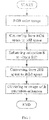
- FIG. 1 is a flowchart of a method for enhancing saturation of an RGB color image using space transformation.
- the color image that is to be processed is converted into HSI space, its saturation is extracted, and the saturation is enhanced using a certain approach to obtain an enhanced saturation value.
- the processed HSI model is converted back to RGB model space using a model transformation formula. After normalization in the RGB model space, each RGB component is within a range of 0 to 1.
- the RGB component obtained from HSI model conversion has a problem that its value may exceed 1. By using a general cut-out approach, color tone may be inconsistent.
- the present invention provides an image processing method for solving image color tone inconsistence caused by being out of the boundaries of color space.
- the present disclosure provides an image processing method, including:
- Step S10 includes:
- Step S20 includes:
- the CMY color space is a color model based on subtractive color mixture
- the present disclosure further provides an image processing method, including:
- Step S10 includes:
- Step S20 includes:
- the CMY color space is a color model based on subtractive color mixture
- the present disclosure provides an image processing method and device. Points of an original image in its color space are filtered. By performing space transformation for the points that may be out of boundary, the present disclosure can efficiently solve the image distortion issue caused by being out of the boundaries of the color space, ensure unchanged color tone, and improve display quality. Also, image saturation is enhanced in the RGB color space and computing power is improved.
- HSI Human, Saturation, Intensity
- HSV Human, Saturation, Value
- FIG. 2 is a flowchart of an image processing method in accordance with a first preferred embodiment of the present disclosure. The method includes the following steps.
- the point A i ( r i , g i , b i ) is selected from the original image.
- Processing each component of the point A i of the original image in the RGB color space is to stretch ( ⁇ ) and translate ( ⁇ ) the components of the point A i in the RGB color space.
- the point A i ( r i , g i , b i ) is selected from the original image.
- the point A i is processed in the RGB color space if max( r 0 , g 0 , b 0 ) ⁇ 1.
- the converted point is processed in the CMY color space. After being processed, the point is converted from the CMY color space to the RGB color space using the fourth function f 4 ( x ) again.
- the CMY color space is a color model based on subtractive color mixture.
- a point A i ( r i , g i , b i ) is selected in the RGB color space, where i is a natural number. After being processed in the RGB color space, the point is noted as A 0 ( r 0 , g 0 , b 0 ).
- the point A i is processed in the RGB space using the second function f 2 ( x ). If max( r 0 , g 0 , b 0 )>1, the point A i is converted into CMY color space using a fourth function f 4 ( x ) and processed in the CMY color space.
- the afore-described method can filter points of the original image and perform space transformation for the points that may be out of boundary to solve the out-of-boundary issue.
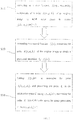
- FIG. 3 is a schematic diagram illustrating a cross section of RGB color space from brightness (0, 0, 0) to (1, 1, 1), where S is saturation and f ( S ) is a saturation enhancing function f 2 ( x ).
- FIG. 3A corresponds to a traditional saturation enhancing method.
- r o , g o , b o are within 0 to 1 after the saturation is enhanced.
- a maximum of r o , g o , b o may exceed the range of 0 to 1, i.e., exceeding the boundary of the color space.
- cut-out approaches are adopted to solve the out-of-boundary issue. However, this may cause a color tone change before and after the image processing.
- FIG. 3B corresponds to an improvement provided in this patent application.
- the points in case 2 are converted into the CMY color space. This can ensure the saturation to be within the range of 0 to 1 and will not cause the out-of-boundary issue.
- the present disclosure further provides an image processing device.
- the device includes an image processing module.
- a point A i ( r i , g i , b i ) is selected from the original image in the RGB color space.
- the image processing is to stretch ( ⁇ ) and translate ( ⁇ ) each component of the point A i of the original image in the RGB color space.
- the point A i ( r i , g i , b i ) is selected from the original image in the RGB color space.
- the converted point is processed in the CMY color space. After being processed, the point is converted from the CMY color space to the RGB color space using the fourth function f 4 ( x ) again.
- the CMY color space is a color model based on subtractive color mixture.
- a point A i ( r i , g i , b i ) is selected in the RGB color space, where i is a natural number. After being processed in the RGB color space, the point is noted as A 0 ( r 0 , g 0 , b 0 ).
- the afore-described method can filter points of the original image and perform space transformation for the points that may be out of boundary to solve the out-of-boundary issue.
- FIG. 4 is a schematic diagram illustrating a cross section of RGB color space from brightness (0, 0, 0) to (1, 1, 1), where S is saturation and f ( S ) is a saturation enhancing function f 2 ( x ).
- FIG. 4A corresponds to a traditional saturation enhancing method.
- r o , g o , b o are within 0 to 1 after the saturation is enhanced.
- a maximum of r o ,g o ,b o may exceed the range of 0 to 1, i.e., exceeding the boundary of the color space.
- cut-out approaches are adopted to solve the out-of-boundary issue. However, this may cause a color tone change before and after the image processing.
- FIG. 4B corresponds to an improvement provided in this patent application.
- the points in case 2 are converted into the CMY color space. This can ensure the saturation to be within the range of 0 to 1 and will not cause the out-of-boundary issue.
- the present disclosure provides an image processing method and device.
- Each component of a certain point of an original image is processed in RGB color space.
- the points of the original image in the RGB color space are filtered according to the processed results.
- the present disclosure can efficiently solve the image distortion issue caused by being out of the boundaries of the color space, ensure unchanged color tone, and improve display quality. Also, image saturation is enhanced in the RGB color space and computing power is improved.
Landscapes
- Engineering & Computer Science (AREA)
- Multimedia (AREA)
- Signal Processing (AREA)
- Physics & Mathematics (AREA)
- General Physics & Mathematics (AREA)
- Theoretical Computer Science (AREA)
- Computer Hardware Design (AREA)
- Computer Vision & Pattern Recognition (AREA)
- Color Image Communication Systems (AREA)
- Image Processing (AREA)
- Facsimile Image Signal Circuits (AREA)
Abstract
Description
- The present disclosure relates to image processing technologies, and more particularly to an image processing method and device.
- With improvements on living standards, demands on display quality of electronic products are increasingly high. In existing skills, in order to improve the display quality, image processing is performed during screen display. During the image processing, it is usually necessary to adjust saturation of images in order to make the display more colorful.
- For color image saturation enhancement, it is very important to ensure no out-of-boundary issue for RGB color space and keep color tone unchanged. Color image enhancement is usually performed in HSI (Hue, Saturation, Intensity) and HSV (Hue, Saturation, Value) spaces through conversion. However, a color space transformation problem will occur in converting processed images back to the RGB space. Generally, cut-out approaches are adopted to map the out-of-boundary values to boundary values. This may cause some details to be lost and cause color tone to be changed. Further, this space transformation approach takes time, and is large in computation consumption and low in efficiency.
-
FIG. 1 is a flowchart of a method for enhancing saturation of an RGB color image using space transformation. First, the color image that is to be processed is converted into HSI space, its saturation is extracted, and the saturation is enhanced using a certain approach to obtain an enhanced saturation value. The processed HSI model is converted back to RGB model space using a model transformation formula. After normalization in the RGB model space, each RGB component is within a range of 0 to 1. The RGB component obtained from HSI model conversion has a problem that its value may exceed 1. By using a general cut-out approach, color tone may be inconsistent. - The present invention provides an image processing method for solving image color tone inconsistence caused by being out of the boundaries of color space.
- To achieve above object, technical schemes provided in the present disclosure are described below.
- The present disclosure provides an image processing method, including:
- Step S10: according to a first function f 1(x), processing components of a point Ai (ri ,gi ,bi ) of an original image in RGB color space to obtain A0 (r0 ,g0 ,b0 )=fi (xi ), where i is a natural number;
- Step S20: according to a second function f 2(x), processing the point Ai (ri ,gi ,bi ) of the original image to obtain a processed saturation S 0 = f 2(xi ) ; and
- Step S30: letting f 2 (xi )=1 to determine the point A 0(r 0,g 0,b 0), and processing the point Ai in the RGB color space if max(r 0,g 0,b 0) ≤ 1; converting the point Aj into CMY color space for image processing if max(r 0,g 0,b 0) > 1.
- In accordance with a preferred embodiment of the present disclosure, Step S10 includes:
- Step S11: selecting the point Ai (ri ,gi ,bi ) from the original image in the RGB color space; and
- Step S12: according to the first function f 1(x), processing each component of the point Ai of the original image in the RGB color space to obtain A 0 (r 0,g 0,b 0)=f 1(xi ),
- In accordance with a preferred embodiment of the present disclosure, Step S20 includes:
- Step S21: selecting the point A i (ri ,gi ,bi ) from the original image in the RGB color space;
- Step S22: according to a third function f 3(x), determining saturation Si = f 3(xi ) of the point Ai (ri ,gi ,bi ) of the original image; and
- Step S23: according to the second function f 2(x), processing the saturation Si of the original image to obtain the processed saturation S 0 = f 2(xi ).
- In accordance with a preferred embodiment of the present disclosure, the saturation of the point Ai (ri ,gi ,bi ) of the original image is

the processed saturation obtained by processing the saturation Si of the original image according to the second function f 2(x) is
- In accordance with a preferred embodiment of the present disclosure, brightness of the original image remains unchanged before and after image processing, and values of α and β in f 1(x) are obtained using S 0 = f2 (xi ) and A0 (r 0,g 0,b 0)=f 1(xi ).
- In accordance with a preferred embodiment of the present disclosure, the CMY color space is a color model based on subtractive color mixture, and the point Ai is processed in the CMY color space using a fourth function f 4(x)=1-x, where x represents each component of the point Ai (ri ,gi ,bi ) in the RGB color space.
- The present disclosure further provides an image processing device, including:
an image processing module configured to process components of a point Ai (ri ,gi ,bi ) of an original image in RGB color space according to a first function f 1(x) to obtain A 0(r0,g0,b0)=f 1(xi ), where i is a natural number, process the point Ai (ri ,gi,bi ) of the original image according to a second function f 2(x) to obtain a processed saturation S 0 = f 2(xi ), determine the point A 0(r 0,g 0,b0 ), process the point Ai in the RGB color space if max(r 0,g 0,b 0) ≤ 1, and convert the point Ai into CMY color space for image processing if max(r 0,g 0,b 0) > 1. - In accordance with a preferred embodiment of the present disclosure, the image processing module is configured to stretch (α) and translate (β) each component of the point Ai of the original image in the RGB color space, where the first function is f1 (x)=αx+β.
- In accordance with a preferred embodiment of the present disclosure, the image processing module is configured to determine saturation Si = f 3(xi ) of the point Ai (ri ,gi ,bi ) of the original image according to a third function f 3(x), where

the image processing module is further configured to process the saturation Si of the original image according to the second function f 2(x) to obtain the processed saturation
- The present disclosure further provides an image processing method, including:
- Step S10: according to a first function f 1(x), processing components of a point Ai (ri ,gi ,bi ) of an original image in RGB color space to obtain A 0(r0 ,g 0,b 0)=f1 (xi ), where i is a natural number;
- Step S20: according to a second function f 2(x), processing the point Ai (ri ,gi ,bi ) of the original image to obtain a processed saturation S 0 = f 2(xi ); and
- Step S30: letting f 2(xi )=1 to determine the point A 0(r 0,g 0,b 0), and processing the point Ai in the RGB color space if max(r 0,g 0,b 0)≤1; using a fourth function f 4(x) to convert the point Ai into CMY color space for image processing if max(r 0,g 0,b 0)>1.
- In accordance with a preferred embodiment of the present disclosure, Step S10 includes:
- Step S11: selecting the point Ai (ri ,gi ,bi ) from the original image in the RGB color space; and
- Step S12: according to the first function f 1(x), processing each component of the point Ai of the original image in the RGB color space to obtain A 0(r 0,g 0,b 0)=f 1(xi ),
- In accordance with a preferred embodiment of the present disclosure, Step S20 includes:
- Step S21: selecting the point Ai (ri ,gi ,bi ) from the original image in the RGB color space;
- Step S22: according to a third function f 3(x), determining saturation Si =f 3(xi ) of the point Ai (ri ,gi ,bi ) of the original image; and
- Step S23: according to the second function f 2(x), processing the saturation Si of the original image to obtain the processed saturation S 0 = f 2(xi ).
- In accordance with a preferred embodiment of the present disclosure, the saturation of the point Ai (ri ,gi ,bi ) of the original image is

the processed saturation obtained by processing the saturation Si of the original image according to the second function f 2(x) is
- In accordance with a preferred embodiment of the present disclosure, brightness of the original image remains unchanged before and after image processing, and values of α and β in f 1(x) are obtained using S 0 = f 2(xi ) and A 0(r 0,g 0,b 0)=f 1(xi ).
- In accordance with a preferred embodiment of the present disclosure, the CMY color space is a color model based on subtractive color mixture, and the point Ai is processed in the CMY color space using a fourth function f 4(x)=1-x, where x represents each component of the point Ai (ri ,gi ,bi ) in the RGB color space.
- Beneficial effects of the present disclosure are described below. The present disclosure provides an image processing method and device. Points of an original image in its color space are filtered. By performing space transformation for the points that may be out of boundary, the present disclosure can efficiently solve the image distortion issue caused by being out of the boundaries of the color space, ensure unchanged color tone, and improve display quality. Also, image saturation is enhanced in the RGB color space and computing power is improved.
- For explaining the technical schemes used in the conventional skills and the embodiments of the present disclosure more clearly, the drawings to be used in descripting the embodiments or the conventional skills will be briefly introduced in the following. Obviously, the drawings below are only some embodiments of the present disclosure, and those of ordinary skill in the art can further obtain other drawings according to these drawings without making any inventive effort.
-
FIG. 1 is a basic image processing flowchart in an existing skill. -
FIG. 2 is a flowchart of an image processing method in accordance with a first embodiment of the present disclosure. -
FIG. 3 illustrates a comparison between an existing skill and the present disclosure in color image saturation enhancing approaches in RGB color space in accordance with a first embodiment of the present disclosure. -
FIG. 4 illustrates a comparison between an existing skill and the present disclosure in color image saturation enhancing approaches in RGB color space in accordance with a second embodiment of the present disclosure. - The following descriptions for the respective embodiments are specific embodiments capable of being implemented for illustrating the present disclosure with referring to the appended figures. In describing the present disclosure, spatially relative terms such as "upper", "lower", "front", "back", "left", "right", "inner", "outer", "lateral", and the like, may be used herein for ease of description as illustrated in the figures. Therefore, the spatially relative terms used herein are intended to illustrate the present disclosure for ease of understanding, but are not intended to limit the present disclosure. In the appending drawings, units with similar structures are indicated by the same reference numbers.
- In existing image processing methods, color images are converted into HSI (Hue, Saturation, Intensity) and HSV (Hue, Saturation, Value) color spaces and are processed in these color spaces. When they are converted back to RGB color space, some details may be lost and color tone may be changed because of being out of the boundaries of the color space. The present disclosure provides an image processing method, and embodiments of the present disclosure can avoid these drawbacks.
-
FIG. 2 is a flowchart of an image processing method in accordance with a first preferred embodiment of the present disclosure. The method includes the following steps. - In Step S10, components of a point Ai (ri ,gi ,bi ) of an original image in RGB color space is processed according to a first function f 1(x) to obtain A 0(r 0,g 0,b 0)=f 1(xi ), where i is a natural number.
- In the RGB color space, the point Ai (ri ,gi ,bi ) is selected from the original image. Each component of the point Ai of the original image is processed in the RGB color space according to the first function f 1(x) to obtain A0 (r 0,g 0,b 0,)=f 1(xi ).
- Processing each component of the point Ai of the original image in the RGB color space is to stretch (α) and translate (β) the components of the point Ai in the RGB color space.
- In Step S20, the point Ai (ri ,gi ,bi ) of the original image is processed according to a second function f 2(x) to obtain a processed saturation S 0 = f 2(xi ).
- In the RGB color space, the point Ai (ri ,gi ,bi ) is selected from the original image. Saturation Si = f 3(xi ) of the point Ai (ri ,gi ,bi ) of the original image is determined according to a third function f 3(x). The saturation Si of the original image is processed according to the second function f 2(x) to obtain the processed saturation S 0 = f 2(xi ).
- The saturation is obtained according to


- Brightness of the original image remains unchanged before and after image processing, and values of α and β in f 1(x) are obtained using S 0 = f 2(xi ) and A 0(r 0,g 0,b 0)=f 1(xi ).
- In Step S30, let f 2(xi )=1 to determine the point A 0(r 0,g 0,b 0). The point Ai is processed in the RGB color space if max(r 0,g 0,b 0)≤1.
- If max(r 0,g 0,b 0)>1, the point Ai is converted into CMY color space for image processing.
- In the above formulas, let f 2;(xi )=1 to determine values of r 0,g 0,b 0 for the point A 0(r 0,g 0,b 0).
- According to a size of the obtained values of r 0,g 0,b 0, select a corresponding color space to process the point Ai .
- If max(r 0,g 0,b 0) ≤ 1, the point Ai is processed in the RGB space using the second function f 2(x). If max(r 0,g 0,b 0) > 1, the point Ai is converted into CMY color space using a fourth function f 4(x) and processed in the CMY color space.
- The converted point is processed in the CMY color space. After being processed, the point is converted from the CMY color space to the RGB color space using the fourth function f 4(x) again.
- The CMY color space is a color model based on subtractive color mixture. The fourth function is f 4(x)=1-x, where x represents each component of the point Ai (ri ,gi ,bi ) in the RGB color space.
- For instance, a point Ai (ri ,gi ,bi ) is selected in the RGB color space, where i is a natural number. After being processed in the RGB color space, the point is noted as A 0(r 0,g 0,b 0).
- (1) The first function f 1(x)=αx+β is used to stretch (α) and translate (β) the point Ai (ri ,gi ,bi ) in the RGB color space to obtain the following equations:



- (2) Brightness of the original image remains unchanged before and after image processing. Based on this principle, the following equations are obtained:


According to equations (1-1) ∼ (1-5), a relation between α and β is obtained:
- (3) Saturation of the point Ai (ri ,gi ,bi ) of the original image is determined according to the third function f 3(x). The following equation is obtained:

- (4) The saturation Si of the original image is processed according to the second function f 2(x) to obtain a processed saturation S 0 as below:

- Accordingly, values of α and β can be obtained according to equations (1-6) and (1-8).
- In equation (1-8), let f 2(x i )=1 to determine values of r 0,g 0,b 0 for the point A 0(r 0,g 0,b 0), According to a size of the obtained values of r 0,g 0,b 0, select a corresponding color space to process the point Ai .
- If max(r 0,g 0,b 0)≤1, the point Ai is processed in the RGB space using the second function f 2(x). If max(r 0,g 0,b 0)>1, the point Ai is converted into CMY color space using a fourth function f 4(x) and processed in the CMY color space.
- (5) According to the fourth function f 4(x), the point Ai (ri ,gi ,bi ) is processed in the CMY color space to obtain a point Ai (ci ,mi ,yi ) in the CMY color space as below:


- (6) The first function f 1(x)=αx+β is used to stretch (α) and translate (β) the point Ai (ci ,mi ,yi ) in the CMY color space to obtain a processed point A 0(c 0,m 0,y 0) as below:


- (7) The saturation Si of the original image is processed according to the second function f 2(x) to obtain a processed saturation S 0 as below:

- (8) The point A 0(c 0,m 0,y 0) is converted from the CMY color space into the RGB color space using the fourth function f 4(x), as below:


- Accordingly, the afore-described method can filter points of the original image and perform space transformation for the points that may be out of boundary to solve the out-of-boundary issue.
-
FIG. 3 is a schematic diagram illustrating a cross section of RGB color space from brightness (0, 0, 0) to (1, 1, 1), where S is saturation and f(S) is a saturation enhancing function f 2(x). -
FIG. 3A corresponds to a traditional saturation enhancing method. Incase 1, ro ,go ,bo are within 0 to 1 after the saturation is enhanced. Incase 2, after the saturation is enhanced, a maximum of ro ,go ,bo may exceed the range of 0 to 1, i.e., exceeding the boundary of the color space. Generally, cut-out approaches are adopted to solve the out-of-boundary issue. However, this may cause a color tone change before and after the image processing. -
FIG. 3B corresponds to an improvement provided in this patent application. As can be seen from this figure, the points incase 2 are converted into the CMY color space. This can ensure the saturation to be within the range of 0 to 1 and will not cause the out-of-boundary issue. - The present disclosure further provides an image processing device. The device includes an image processing module.
- Firstly, in the image processing module, a point Ai (ri ,gi ,bi ) is selected from the original image in the RGB color space. Each component of the point Ai of the original image is processed in the RGB color space according to the first function f 1(x)=αx+β to obtain a processed point A0 (r 0,g 0,b 0)=f 1(xi ).
- The image processing is to stretch (α) and translate (β) each component of the point Ai of the original image in the RGB color space.
- After that, in the image processing module, the point Ai (ri ,gi ,bi ) is selected from the original image in the RGB color space. Saturation Si =f 3(xi ) of the point Ai (ri ,gi ,bi ) of the original image is determined according to the third function f 3(x). The saturation Si of the original image is processed according to the second function f 2(x) to obtain a processed saturation S 0 = f 2(xi ).
- The saturation is obtained according to


- Brightness of the original image remains unchanged before and after image processing, and values of α and β in f 1(x) are obtained using S 0=f 2(xi ) and A0 (r 0,g 0,b 0)=f 1(xi ).
- Finally, in the image processing module, let f 2(xi )=1 to determine values r 0,g 0,b 0 of for the point A 0(r 0,g 0,b 0). According to a size of the obtained values of r 0,g 0,b 0, select a corresponding color space to process the point Ai .
- If max(r 0,g 0,b 0) ≤ 1, the point Ai is processed in the RGB space using the second function f 2(x). If max(r 0,g 0,b 0) > 1, the point Ai is converted into CMY color space using a fourth function f 4(x) and processed in the CMY color space.
- The converted point is processed in the CMY color space. After being processed, the point is converted from the CMY color space to the RGB color space using the fourth function f 4(x) again.
- The CMY color space is a color model based on subtractive color mixture. The fourth function is f 4(x)=1-x, where x represents each component of the point Ai (ri ,gi ,bi ) in the RGB color space.
- For instance, a point Ai (ri ,gi ,bi ) is selected in the RGB color space, where i is a natural number. After being processed in the RGB color space, the point is noted as A 0(r 0,g 0,b 0).
- (1) The first function f 1(x)=αx+β is used to stretch (α) and translate (β) the point Ai (ri ,gi ,bi ) in the RGB color space to obtain the following equations:



- (2) Brightness of the original image remains unchanged before and after image processing. Based on this principle, the following equations are obtained:


According to equations (2-1) ∼ (2-5), a relation between α and β is obtained:
- (3) Saturation of the point Ai (ri ,gi ,bi ) of the original image is determined according to the third function f 3(x). The following equation is obtained:

- (4) The saturation Si of the original image is processed according to the second function f 2(x) to obtain a processed saturation S 0 as below:

- Accordingly, values of α and β can be obtained according to equations (2-6) and (2-8).
- In equation (2-8), let f 2(xi )=1 to determine values of r 0,g 0,b 0 for the point A 0(r 0,g 0,b 0). According to a size of the obtained values of r 0,g 0,b 0, select a corresponding color space to process the point Ai.
- If max(r 0,g 0,b 0) ≤ 1, the point Ai is processed in the RGB space using the second function f 2(x). If max(r 0,g 0,b 0)>1, the point Ai is converted into CMY color space using a fourth function f 4(x) and processed in the CMY color space.
- (5) According to the fourth function f 4(x), the point Ai (ri ,gi ,bi ) is processed in the CMY color space to obtain a point Ai (ci ,mi ,yi ) in the CMY color space as below:


- (6) The first function f 1(x)=αx+β is used to stretch (α) and translate (β) the point Ai (ci ,mi ,yi ) in the CMY color space to obtain a processed point A 0(c 0,m 0,y 0) as below:


- (7) The saturation Si of the original image is processed according to the second function f 2(x) to obtain a processed saturation S 0 as below:

- (8) The point A 0(c 0,m 0,y 0) is converted from the CMY color space into the RGB color space using the fourth function f 4(x), as below:


- Accordingly, the afore-described method can filter points of the original image and perform space transformation for the points that may be out of boundary to solve the out-of-boundary issue.
-
FIG. 4 is a schematic diagram illustrating a cross section of RGB color space from brightness (0, 0, 0) to (1, 1, 1), where S is saturation and f(S) is a saturation enhancing function f 2(x). -
FIG. 4A corresponds to a traditional saturation enhancing method. Incase 1, ro ,go ,bo are within 0 to 1 after the saturation is enhanced. Incase 2, after the saturation is enhanced, a maximum of ro,go,bo may exceed the range of 0 to 1, i.e., exceeding the boundary of the color space. Generally, cut-out approaches are adopted to solve the out-of-boundary issue. However, this may cause a color tone change before and after the image processing. -
FIG. 4B corresponds to an improvement provided in this patent application. As can be seen from this figure, the points incase 2 are converted into the CMY color space. This can ensure the saturation to be within the range of 0 to 1 and will not cause the out-of-boundary issue. - The present disclosure provides an image processing method and device. Each component of a certain point of an original image is processed in RGB color space. The points of the original image in the RGB color space are filtered according to the processed results. By performing space transformation for the points that may be out of the boundary and converting them from the RGB color space into CMY color space, the present disclosure can efficiently solve the image distortion issue caused by being out of the boundaries of the color space, ensure unchanged color tone, and improve display quality. Also, image saturation is enhanced in the RGB color space and computing power is improved.
- Above all, while the preferred embodiments of the present disclosure have been illustrated and described in detail, various modifications and alterations can be made by persons skilled in this art. The embodiment of the present disclosure is therefore described in an illustrative but not restrictive sense. It is intended that the present disclosure should not be limited to the particular forms as illustrated, and that all modifications and alterations which maintain the spirit and realm of the present disclosure are within the scope as defined in the appended claims.
Claims (15)
- An image processing method, comprising:Step S10: according to a first function ƒ 1(x), processing components of a point Ai (ri , gi , bi ) of an original image in RGB color space to obtain A 0(r 0, g 0, b 0) =ƒ 1(xi ), where i is a natural number;Step S20: according to a second function ƒ 2(x), processing the point Ai (ri,gi,bi ) of the original image to obtain a processed saturation S 0 = ƒ 2(xi ) ; andStep S30: letting ƒ 2(xi )=1 to determine the point A 0(r 0 ,g 0 ,b 0), and processing the point Ai in the RGB color space if max(r 0,g 0,b 0)≤1; converting the point Ai into CMY color space for image processing if max(r 0,g 0,b 0)>1.
- The method according to claim 1, wherein Step S10 comprises:Step S11: selecting the point Ai (ri,gi,bi ) from the original image in the RGB color space; andStep S12: according to the first function ƒ 1(x), processing each component of the point Ai of the original image in the RGB color space to obtain A 0(r 0 ,g 0 ,b 0)=ƒ 1(xi ),wherein processing each component of the point Ai of the original image in the RGB color space is to stretch (α) and translate (β) the components of the point Ai in the RGB color space, where the first function is ƒ 1 (x)=αx+β.
- The method according to claim 1, wherein Step S20 comprises:Step S21: selecting the point Ai (ri ,gi ,bi ) from the original image in the RGB color space;Step S22: according to a third function ƒ 3(x), determining saturation Si = ƒ 3(xi ) of the point Ai (ri,gi,bi ) of the original image; andStep S23: according to the second function ƒ 2(x), processing the saturation Si of the original image to obtain the processed saturation S 0 = ƒ 2(xi ).
- The method according to claim 3, wherein the saturation of the point Ai (ri,gi,bi ) of the original image is

the processed saturation obtained by processing the saturation Si of the original image according to the second function ƒ 2(x) is
- The method according to claim 1, wherein brightness of the original image remains unchanged before and after image processing, and values of α and β in ƒ 1(x) are obtained using S 0 = ƒ 2(xi ) and A 0(r 0 ,g 0 ,b 0)=ƒi (x).
- The method according to claim 1, wherein the CMY color space is a color model based on subtractive color mixture, and the point Ai is processed in the CMY color space using a fourth function ƒ 4(x)=1-x, where x represents each component of the point Ai (ri , gi,bi ) in the RGB color space.
- An image processing device, comprising:
an image processing module configured to process components of a point Ai (ri,gi,bi ) of an original image in RGB color space according to a first function ƒ 1(x) to obtain A 0(r 0 ,g 0 ,b 0)=f 1(xi ), where i is a natural number, process the point Ai (ri,gi,bi ) of the original image according to a second function f 2(x) to obtain a processed saturation S 0 = ƒ2 (xi ), determine the point A 0(r 0 ,g 0 ,b 0), process the point Ai in the RGB color space if max(r 0,g 0,b 0)≤1, and convert the point Ai into CMY color space for image processing if max(r 0,g 0,b 0)>1. - The device according to claim 7, wherein the image processing module is configured to stretch (α) and translate (β) each component of the point Ai of the original image in the RGB color space, where the first function is ƒ 1(x)=αx+β.
- The device according to claim 7, wherein the image processing module is configured to determine saturation Si = ƒ 3(xi ) of the point Ai (ri,gi,bi ) of the original image according to a third function f3 (x), where

the image processing module is further configured to process the saturation Si of the original image according to the second function ƒ2 (x) to obtain the processed saturation
- An image processing method, comprising:Step S10: according to a first function ƒ 1(x), processing components of a point Ai (ri,gi,bi ) of an original image in RGB color space to obtain A 0(r 0 ,g 0 ,b 0)=ƒ 1(xi ), where i is a natural number;Step S20: according to a second function ƒ 2(x), processing the point Ai (ri,gi,bi ) of the original image to obtain a processed saturation S 0 = ƒ2 (xi ); andStep S30: letting ƒ 2(xi )=1 to determine the point A 0(r 0 ,g 0 ,b 0), and processing the point Ai in the RGB color space if max(r 0,g0,b 0)≤1 ; using a fourth function ƒ 4(x) to convert the point Ai into CMY color space for image processing if max(r 0,g 0,b 0)>1.
- The method according to claim 10, wherein Step S10 comprises:Step S11: selecting the point Ai (ri,gi,bi ) from the original image in the RGB color space; andStep S12: according to the first function ƒ 1(x), processing each component of the point Ai of the original image in the RGB color space to obtain A 0(r 0 ,g 0 ,b 0)=ƒ 1(xi ),wherein processing each component of the point Ai of the original image in the RGB color space is to stretch (α) and translate (β) the components of the point Ai in the RGB color space, where the first function is ƒ 1(x)=αx+β.
- The method according to claim 10, wherein Step S20 comprises:Step S21: selecting the point Ai (ri,gi,bi ) from the original image in the RGB color space;Step S22: according to a third function ƒ 3(x), determining saturation Si =ƒ 3(xi ) of the point Ai (ri ,gi ,bi ) of the original image; andStep S23: according to the second function ƒ 2(x), processing the saturation Si of the original image to obtain the processed saturation S 0 = ƒ 2(xi ).
- The method according to claim 12, wherein the saturation of the point Ai (ri,gi,bi ) of the original image is

the processed saturation obtained by processing the saturation Si of the original image according to the second function ƒ 2(x) is
- The method according to claim 10, wherein brightness of the original image remains unchanged before and after image processing, and values of α and β in ƒ 1(x) are obtained using S 0 = ƒ 2(xi ) and A 0(r 0,g 0,b 0)=ƒ 1(xi ).
- The method according to claim 10, wherein the CMY color space is a color model based on subtractive color mixture, and the point Ai is processed in the CMY color space using a fourth function ƒ 4(x)=1-x, where x represents each component of the point Ai (ri ,gi,bi ) in the RGB color space.
Applications Claiming Priority (2)
| Application Number | Priority Date | Filing Date | Title |
|---|---|---|---|
| CN201710760193.4A CN107610186B (en) | 2017-08-30 | 2017-08-30 | An image processing method and device |
| PCT/CN2017/114520 WO2019041618A1 (en) | 2017-08-30 | 2017-12-05 | Image processing method and device |
Publications (3)
| Publication Number | Publication Date |
|---|---|
| EP3678369A1 true EP3678369A1 (en) | 2020-07-08 |
| EP3678369A4 EP3678369A4 (en) | 2021-04-21 |
| EP3678369B1 EP3678369B1 (en) | 2022-06-08 |
Family
ID=61056727
Family Applications (1)
| Application Number | Title | Priority Date | Filing Date |
|---|---|---|---|
| EP17923124.6A Not-in-force EP3678369B1 (en) | 2017-08-30 | 2017-12-05 | Image processing method and device |
Country Status (7)
| Country | Link |
|---|---|
| US (1) | US10366516B2 (en) |
| EP (1) | EP3678369B1 (en) |
| JP (1) | JP7030958B2 (en) |
| KR (1) | KR102362463B1 (en) |
| CN (1) | CN107610186B (en) |
| PL (1) | PL3678369T3 (en) |
| WO (1) | WO2019041618A1 (en) |
Families Citing this family (2)
| Publication number | Priority date | Publication date | Assignee | Title |
|---|---|---|---|---|
| CN108711142B (en) * | 2018-05-22 | 2020-09-29 | 深圳市华星光电技术有限公司 | Image processing method and image processing apparatus |
| CN110766636B (en) * | 2019-10-28 | 2022-06-07 | 河南大学 | Intelligent image processing method for AI chip |
Family Cites Families (15)
| Publication number | Priority date | Publication date | Assignee | Title |
|---|---|---|---|---|
| US5359436A (en) * | 1992-11-12 | 1994-10-25 | Linotype-Hell Ag | Black recalculation for arbitrary HSL corrections in CMY color space |
| JP2001218078A (en) | 1999-11-25 | 2001-08-10 | Fuji Photo Film Co Ltd | Chroma correction apparatus and method |
| JP2002330299A (en) * | 2001-05-01 | 2002-11-15 | Seiko Epson Corp | Image processing apparatus, image processing method, program, and recording medium |
| CN1294530C (en) * | 2001-11-05 | 2007-01-10 | 夏普株式会社 | Color image processing method, color image processor, color display, and computer program for implementing color image processing method |
| JP4375580B2 (en) * | 2005-03-30 | 2009-12-02 | 日本電気株式会社 | Image processing apparatus, image processing method, and image processing program |
| GB0804337D0 (en) * | 2008-03-07 | 2008-04-16 | Cambridge Silicon Radio Ltd | Dual phase detector phase-locked loop |
| CN101719361B (en) * | 2008-10-09 | 2012-04-11 | 华硕电脑股份有限公司 | Saturation adjusting method and saturation adjusting module |
| CN101729913B (en) * | 2008-10-14 | 2012-11-28 | 华映视讯(吴江)有限公司 | Method and system for adjusting image saturation |
| TWI538474B (en) * | 2011-03-15 | 2016-06-11 | 杜比實驗室特許公司 | Method and device for converting image data |
| US9449578B2 (en) * | 2011-09-21 | 2016-09-20 | Stmicroelectronics (Grenoble 2) Sas | Circuitry for image processing |
| CN102752605A (en) * | 2011-09-30 | 2012-10-24 | 新奥特(北京)视频技术有限公司 | Method and system for regulating image/video color saturation degree |
| CN102779330B (en) * | 2012-06-13 | 2014-08-06 | 京东方科技集团股份有限公司 | Image reinforcement method, image reinforcement device and display device |
| JP2015152645A (en) * | 2014-02-10 | 2015-08-24 | シナプティクス・ディスプレイ・デバイス合同会社 | Image processing apparatus, image processing method, display panel driver, and display apparatus |
| CN104243946B (en) * | 2014-09-26 | 2017-04-19 | 深圳市华星光电技术有限公司 | Image color enhancement method and device for display |
| US10019970B2 (en) * | 2015-02-24 | 2018-07-10 | Barco N.V. | Steady color presentation manager |
-
2017
- 2017-08-30 CN CN201710760193.4A patent/CN107610186B/en not_active Expired - Fee Related
- 2017-12-05 EP EP17923124.6A patent/EP3678369B1/en not_active Not-in-force
- 2017-12-05 WO PCT/CN2017/114520 patent/WO2019041618A1/en not_active Ceased
- 2017-12-05 US US15/736,039 patent/US10366516B2/en not_active Expired - Fee Related
- 2017-12-05 PL PL17923124.6T patent/PL3678369T3/en unknown
- 2017-12-05 JP JP2020512529A patent/JP7030958B2/en not_active Expired - Fee Related
- 2017-12-05 KR KR1020207008696A patent/KR102362463B1/en not_active Expired - Fee Related
Also Published As
| Publication number | Publication date |
|---|---|
| US10366516B2 (en) | 2019-07-30 |
| EP3678369A4 (en) | 2021-04-21 |
| US20190066339A1 (en) | 2019-02-28 |
| JP7030958B2 (en) | 2022-03-07 |
| KR20200041374A (en) | 2020-04-21 |
| PL3678369T3 (en) | 2022-10-03 |
| CN107610186A (en) | 2018-01-19 |
| KR102362463B1 (en) | 2022-02-14 |
| CN107610186B (en) | 2020-12-22 |
| JP2020532246A (en) | 2020-11-05 |
| WO2019041618A1 (en) | 2019-03-07 |
| EP3678369B1 (en) | 2022-06-08 |
Similar Documents
| Publication | Publication Date | Title |
|---|---|---|
| CN102779330B (en) | Image reinforcement method, image reinforcement device and display device | |
| CN105009580B (en) | The display management of high dynamic range video | |
| CN103248793B (en) | Skin color optimization method and device for color gamut conversion system | |
| CN101082992A (en) | Drawing of real time high dynamic range image and display process | |
| CN105243641B (en) | A kind of low light image Enhancement Method based on dual-tree complex wavelet transform | |
| CN103295206B (en) | A kind of twilight image Enhancement Method and device based on Retinex | |
| CN106355563A (en) | Image defogging method and device | |
| CN107424124B (en) | Image enhancement method and device | |
| CN109389560A (en) | A kind of adaptive weighted filter image denoising method, device and image processing equipment | |
| CN101742340A (en) | Method and device for optimizing and editing image | |
| CN104463806B (en) | Height adaptive method for enhancing picture contrast based on data driven technique | |
| CN105427265B (en) | A kind of method for enhancing color image contrast ratio and system | |
| CN105976405A (en) | RGB image processing method and system | |
| EP3678369A1 (en) | Image processing method and device | |
| CN106971380A (en) | A kind of contrast enhancing and application of the visual saliency optimization method in golf course figure | |
| DE102015113930B4 (en) | Image processing device, image processing system and method for image processing | |
| CN102881004A (en) | Digital image enhancement method based on optic nerve network | |
| CN106127708A (en) | A kind of colored eye fundus image Enhancement Method based on LAB color space | |
| CN109636739B (en) | Detail processing method and device for enhancing image saturation | |
| US8351724B2 (en) | Blue sky color detection technique | |
| CN104732495A (en) | Automatic-toning image processing method and system based on fuzzing | |
| US8284316B2 (en) | Real-time image processing circuit capable of enhancing brightness contrast and color saturation | |
| CN103971336B (en) | Adjusting method, device and equipment for image lightness | |
| CN109544495A (en) | A kind of SoC chip image procossing fusion method based on gaussian filtering and ratio transformation | |
| CN104093010A (en) | Image processing method and device |
Legal Events
| Date | Code | Title | Description |
|---|---|---|---|
| STAA | Information on the status of an ep patent application or granted ep patent |
Free format text: STATUS: THE INTERNATIONAL PUBLICATION HAS BEEN MADE |
|
| PUAI | Public reference made under article 153(3) epc to a published international application that has entered the european phase |
Free format text: ORIGINAL CODE: 0009012 |
|
| STAA | Information on the status of an ep patent application or granted ep patent |
Free format text: STATUS: REQUEST FOR EXAMINATION WAS MADE |
|
| 17P | Request for examination filed |
Effective date: 20200326 |
|
| AK | Designated contracting states |
Kind code of ref document: A1 Designated state(s): AL AT BE BG CH CY CZ DE DK EE ES FI FR GB GR HR HU IE IS IT LI LT LU LV MC MK MT NL NO PL PT RO RS SE SI SK SM TR |
|
| AX | Request for extension of the european patent |
Extension state: BA ME |
|
| DAV | Request for validation of the european patent (deleted) | ||
| DAX | Request for extension of the european patent (deleted) | ||
| A4 | Supplementary search report drawn up and despatched |
Effective date: 20210322 |
|
| RIC1 | Information provided on ipc code assigned before grant |
Ipc: H04N 9/64 20060101AFI20210316BHEP Ipc: G06T 7/90 20170101ALI20210316BHEP Ipc: H04N 1/60 20060101ALI20210316BHEP Ipc: H04N 9/68 20060101ALI20210316BHEP Ipc: H04N 9/77 20060101ALI20210316BHEP |
|
| GRAP | Despatch of communication of intention to grant a patent |
Free format text: ORIGINAL CODE: EPIDOSNIGR1 |
|
| STAA | Information on the status of an ep patent application or granted ep patent |
Free format text: STATUS: GRANT OF PATENT IS INTENDED |
|
| RIC1 | Information provided on ipc code assigned before grant |
Ipc: G06T 5/00 20060101ALI20220112BHEP Ipc: H04N 1/60 20060101ALI20220112BHEP Ipc: H04N 9/68 20060101ALI20220112BHEP Ipc: H04N 9/77 20060101ALI20220112BHEP Ipc: H04N 9/64 20060101AFI20220112BHEP |
|
| INTG | Intention to grant announced |
Effective date: 20220208 |
|
| GRAS | Grant fee paid |
Free format text: ORIGINAL CODE: EPIDOSNIGR3 |
|
| GRAA | (expected) grant |
Free format text: ORIGINAL CODE: 0009210 |
|
| STAA | Information on the status of an ep patent application or granted ep patent |
Free format text: STATUS: THE PATENT HAS BEEN GRANTED |
|
| AK | Designated contracting states |
Kind code of ref document: B1 Designated state(s): AL AT BE BG CH CY CZ DE DK EE ES FI FR GB GR HR HU IE IS IT LI LT LU LV MC MK MT NL NO PL PT RO RS SE SI SK SM TR |
|
| REG | Reference to a national code |
Ref country code: AT Ref legal event code: REF Ref document number: 1497727 Country of ref document: AT Kind code of ref document: T Effective date: 20220615 Ref country code: CH Ref legal event code: EP |
|
| REG | Reference to a national code |
Ref country code: DE Ref legal event code: R096 Ref document number: 602017058437 Country of ref document: DE |
|
| REG | Reference to a national code |
Ref country code: IE Ref legal event code: FG4D |
|
| REG | Reference to a national code |
Ref country code: LT Ref legal event code: MG9D |
|
| REG | Reference to a national code |
Ref country code: NL Ref legal event code: MP Effective date: 20220608 |
|
| PG25 | Lapsed in a contracting state [announced via postgrant information from national office to epo] |
Ref country code: SE Free format text: LAPSE BECAUSE OF FAILURE TO SUBMIT A TRANSLATION OF THE DESCRIPTION OR TO PAY THE FEE WITHIN THE PRESCRIBED TIME-LIMIT Effective date: 20220608 Ref country code: NO Free format text: LAPSE BECAUSE OF FAILURE TO SUBMIT A TRANSLATION OF THE DESCRIPTION OR TO PAY THE FEE WITHIN THE PRESCRIBED TIME-LIMIT Effective date: 20220908 Ref country code: LT Free format text: LAPSE BECAUSE OF FAILURE TO SUBMIT A TRANSLATION OF THE DESCRIPTION OR TO PAY THE FEE WITHIN THE PRESCRIBED TIME-LIMIT Effective date: 20220608 Ref country code: HR Free format text: LAPSE BECAUSE OF FAILURE TO SUBMIT A TRANSLATION OF THE DESCRIPTION OR TO PAY THE FEE WITHIN THE PRESCRIBED TIME-LIMIT Effective date: 20220608 Ref country code: GR Free format text: LAPSE BECAUSE OF FAILURE TO SUBMIT A TRANSLATION OF THE DESCRIPTION OR TO PAY THE FEE WITHIN THE PRESCRIBED TIME-LIMIT Effective date: 20220909 Ref country code: FI Free format text: LAPSE BECAUSE OF FAILURE TO SUBMIT A TRANSLATION OF THE DESCRIPTION OR TO PAY THE FEE WITHIN THE PRESCRIBED TIME-LIMIT Effective date: 20220608 Ref country code: ES Free format text: LAPSE BECAUSE OF FAILURE TO SUBMIT A TRANSLATION OF THE DESCRIPTION OR TO PAY THE FEE WITHIN THE PRESCRIBED TIME-LIMIT Effective date: 20220608 Ref country code: BG Free format text: LAPSE BECAUSE OF FAILURE TO SUBMIT A TRANSLATION OF THE DESCRIPTION OR TO PAY THE FEE WITHIN THE PRESCRIBED TIME-LIMIT Effective date: 20220908 |
|
| REG | Reference to a national code |
Ref country code: AT Ref legal event code: MK05 Ref document number: 1497727 Country of ref document: AT Kind code of ref document: T Effective date: 20220608 |
|
| PG25 | Lapsed in a contracting state [announced via postgrant information from national office to epo] |
Ref country code: RS Free format text: LAPSE BECAUSE OF FAILURE TO SUBMIT A TRANSLATION OF THE DESCRIPTION OR TO PAY THE FEE WITHIN THE PRESCRIBED TIME-LIMIT Effective date: 20220608 Ref country code: LV Free format text: LAPSE BECAUSE OF FAILURE TO SUBMIT A TRANSLATION OF THE DESCRIPTION OR TO PAY THE FEE WITHIN THE PRESCRIBED TIME-LIMIT Effective date: 20220608 |
|
| PG25 | Lapsed in a contracting state [announced via postgrant information from national office to epo] |
Ref country code: NL Free format text: LAPSE BECAUSE OF FAILURE TO SUBMIT A TRANSLATION OF THE DESCRIPTION OR TO PAY THE FEE WITHIN THE PRESCRIBED TIME-LIMIT Effective date: 20220608 |
|
| PG25 | Lapsed in a contracting state [announced via postgrant information from national office to epo] |
Ref country code: SM Free format text: LAPSE BECAUSE OF FAILURE TO SUBMIT A TRANSLATION OF THE DESCRIPTION OR TO PAY THE FEE WITHIN THE PRESCRIBED TIME-LIMIT Effective date: 20220608 Ref country code: SK Free format text: LAPSE BECAUSE OF FAILURE TO SUBMIT A TRANSLATION OF THE DESCRIPTION OR TO PAY THE FEE WITHIN THE PRESCRIBED TIME-LIMIT Effective date: 20220608 Ref country code: RO Free format text: LAPSE BECAUSE OF FAILURE TO SUBMIT A TRANSLATION OF THE DESCRIPTION OR TO PAY THE FEE WITHIN THE PRESCRIBED TIME-LIMIT Effective date: 20220608 Ref country code: PT Free format text: LAPSE BECAUSE OF FAILURE TO SUBMIT A TRANSLATION OF THE DESCRIPTION OR TO PAY THE FEE WITHIN THE PRESCRIBED TIME-LIMIT Effective date: 20221010 Ref country code: EE Free format text: LAPSE BECAUSE OF FAILURE TO SUBMIT A TRANSLATION OF THE DESCRIPTION OR TO PAY THE FEE WITHIN THE PRESCRIBED TIME-LIMIT Effective date: 20220608 Ref country code: CZ Free format text: LAPSE BECAUSE OF FAILURE TO SUBMIT A TRANSLATION OF THE DESCRIPTION OR TO PAY THE FEE WITHIN THE PRESCRIBED TIME-LIMIT Effective date: 20220608 Ref country code: AT Free format text: LAPSE BECAUSE OF FAILURE TO SUBMIT A TRANSLATION OF THE DESCRIPTION OR TO PAY THE FEE WITHIN THE PRESCRIBED TIME-LIMIT Effective date: 20220608 |
|
| PG25 | Lapsed in a contracting state [announced via postgrant information from national office to epo] |
Ref country code: IS Free format text: LAPSE BECAUSE OF FAILURE TO SUBMIT A TRANSLATION OF THE DESCRIPTION OR TO PAY THE FEE WITHIN THE PRESCRIBED TIME-LIMIT Effective date: 20221008 |
|
| REG | Reference to a national code |
Ref country code: DE Ref legal event code: R097 Ref document number: 602017058437 Country of ref document: DE |
|
| PG25 | Lapsed in a contracting state [announced via postgrant information from national office to epo] |
Ref country code: AL Free format text: LAPSE BECAUSE OF FAILURE TO SUBMIT A TRANSLATION OF THE DESCRIPTION OR TO PAY THE FEE WITHIN THE PRESCRIBED TIME-LIMIT Effective date: 20220608 |
|
| PLBE | No opposition filed within time limit |
Free format text: ORIGINAL CODE: 0009261 |
|
| STAA | Information on the status of an ep patent application or granted ep patent |
Free format text: STATUS: NO OPPOSITION FILED WITHIN TIME LIMIT |
|
| PG25 | Lapsed in a contracting state [announced via postgrant information from national office to epo] |
Ref country code: DK Free format text: LAPSE BECAUSE OF FAILURE TO SUBMIT A TRANSLATION OF THE DESCRIPTION OR TO PAY THE FEE WITHIN THE PRESCRIBED TIME-LIMIT Effective date: 20220608 |
|
| 26N | No opposition filed |
Effective date: 20230310 |
|
| PG25 | Lapsed in a contracting state [announced via postgrant information from national office to epo] |
Ref country code: SI Free format text: LAPSE BECAUSE OF FAILURE TO SUBMIT A TRANSLATION OF THE DESCRIPTION OR TO PAY THE FEE WITHIN THE PRESCRIBED TIME-LIMIT Effective date: 20220608 |
|
| REG | Reference to a national code |
Ref country code: DE Ref legal event code: R119 Ref document number: 602017058437 Country of ref document: DE |
|
| P01 | Opt-out of the competence of the unified patent court (upc) registered |
Effective date: 20230530 |
|
| REG | Reference to a national code |
Ref country code: CH Ref legal event code: PL |
|
| GBPC | Gb: european patent ceased through non-payment of renewal fee |
Effective date: 20221205 |
|
| REG | Reference to a national code |
Ref country code: BE Ref legal event code: MM Effective date: 20221231 |
|
| PG25 | Lapsed in a contracting state [announced via postgrant information from national office to epo] |
Ref country code: LU Free format text: LAPSE BECAUSE OF NON-PAYMENT OF DUE FEES Effective date: 20221205 |
|
| PG25 | Lapsed in a contracting state [announced via postgrant information from national office to epo] |
Ref country code: LI Free format text: LAPSE BECAUSE OF NON-PAYMENT OF DUE FEES Effective date: 20221231 Ref country code: IE Free format text: LAPSE BECAUSE OF NON-PAYMENT OF DUE FEES Effective date: 20221205 Ref country code: GB Free format text: LAPSE BECAUSE OF NON-PAYMENT OF DUE FEES Effective date: 20221205 Ref country code: DE Free format text: LAPSE BECAUSE OF NON-PAYMENT OF DUE FEES Effective date: 20230701 Ref country code: CH Free format text: LAPSE BECAUSE OF NON-PAYMENT OF DUE FEES Effective date: 20221231 |
|
| PG25 | Lapsed in a contracting state [announced via postgrant information from national office to epo] |
Ref country code: FR Free format text: LAPSE BECAUSE OF NON-PAYMENT OF DUE FEES Effective date: 20221231 Ref country code: BE Free format text: LAPSE BECAUSE OF NON-PAYMENT OF DUE FEES Effective date: 20221231 |
|
| PG25 | Lapsed in a contracting state [announced via postgrant information from national office to epo] |
Ref country code: IT Free format text: LAPSE BECAUSE OF FAILURE TO SUBMIT A TRANSLATION OF THE DESCRIPTION OR TO PAY THE FEE WITHIN THE PRESCRIBED TIME-LIMIT Effective date: 20220608 |
|
| PG25 | Lapsed in a contracting state [announced via postgrant information from national office to epo] |
Ref country code: HU Free format text: LAPSE BECAUSE OF FAILURE TO SUBMIT A TRANSLATION OF THE DESCRIPTION OR TO PAY THE FEE WITHIN THE PRESCRIBED TIME-LIMIT; INVALID AB INITIO Effective date: 20171205 |
|
| PG25 | Lapsed in a contracting state [announced via postgrant information from national office to epo] |
Ref country code: CY Free format text: LAPSE BECAUSE OF FAILURE TO SUBMIT A TRANSLATION OF THE DESCRIPTION OR TO PAY THE FEE WITHIN THE PRESCRIBED TIME-LIMIT Effective date: 20220608 |
|
| PG25 | Lapsed in a contracting state [announced via postgrant information from national office to epo] |
Ref country code: PL Free format text: LAPSE BECAUSE OF NON-PAYMENT OF DUE FEES Effective date: 20221205 Ref country code: MK Free format text: LAPSE BECAUSE OF FAILURE TO SUBMIT A TRANSLATION OF THE DESCRIPTION OR TO PAY THE FEE WITHIN THE PRESCRIBED TIME-LIMIT Effective date: 20220608 |
|
| PG25 | Lapsed in a contracting state [announced via postgrant information from national office to epo] |
Ref country code: MC Free format text: LAPSE BECAUSE OF FAILURE TO SUBMIT A TRANSLATION OF THE DESCRIPTION OR TO PAY THE FEE WITHIN THE PRESCRIBED TIME-LIMIT Effective date: 20220608 |
|
| PG25 | Lapsed in a contracting state [announced via postgrant information from national office to epo] |
Ref country code: TR Free format text: LAPSE BECAUSE OF FAILURE TO SUBMIT A TRANSLATION OF THE DESCRIPTION OR TO PAY THE FEE WITHIN THE PRESCRIBED TIME-LIMIT Effective date: 20220608 Ref country code: MC Free format text: LAPSE BECAUSE OF FAILURE TO SUBMIT A TRANSLATION OF THE DESCRIPTION OR TO PAY THE FEE WITHIN THE PRESCRIBED TIME-LIMIT Effective date: 20220608 |
|
| PG25 | Lapsed in a contracting state [announced via postgrant information from national office to epo] |
Ref country code: MT Free format text: LAPSE BECAUSE OF FAILURE TO SUBMIT A TRANSLATION OF THE DESCRIPTION OR TO PAY THE FEE WITHIN THE PRESCRIBED TIME-LIMIT Effective date: 20220608 |
|
| PG25 | Lapsed in a contracting state [announced via postgrant information from national office to epo] |
Ref country code: BG Free format text: LAPSE BECAUSE OF FAILURE TO SUBMIT A TRANSLATION OF THE DESCRIPTION OR TO PAY THE FEE WITHIN THE PRESCRIBED TIME-LIMIT Effective date: 20220608 |
|
| PG25 | Lapsed in a contracting state [announced via postgrant information from national office to epo] |
Ref country code: BG Free format text: LAPSE BECAUSE OF FAILURE TO SUBMIT A TRANSLATION OF THE DESCRIPTION OR TO PAY THE FEE WITHIN THE PRESCRIBED TIME-LIMIT Effective date: 20220608 |