EP3678335B1 - Method and device for detecting communication connection - Google Patents
Method and device for detecting communication connection Download PDFInfo
- Publication number
- EP3678335B1 EP3678335B1 EP18857533.6A EP18857533A EP3678335B1 EP 3678335 B1 EP3678335 B1 EP 3678335B1 EP 18857533 A EP18857533 A EP 18857533A EP 3678335 B1 EP3678335 B1 EP 3678335B1
- Authority
- EP
- European Patent Office
- Prior art keywords
- network node
- packet
- data traffic
- nhrp
- sent
- Prior art date
- Legal status (The legal status is an assumption and is not a legal conclusion. Google has not performed a legal analysis and makes no representation as to the accuracy of the status listed.)
- Active
Links
Images



Classifications
-
- H—ELECTRICITY
- H04—ELECTRIC COMMUNICATION TECHNIQUE
- H04L—TRANSMISSION OF DIGITAL INFORMATION, e.g. TELEGRAPHIC COMMUNICATION
- H04L43/00—Arrangements for monitoring or testing data switching networks
- H04L43/08—Monitoring or testing based on specific metrics, e.g. QoS, energy consumption or environmental parameters
- H04L43/0805—Monitoring or testing based on specific metrics, e.g. QoS, energy consumption or environmental parameters by checking availability
- H04L43/0811—Monitoring or testing based on specific metrics, e.g. QoS, energy consumption or environmental parameters by checking availability by checking connectivity
-
- H—ELECTRICITY
- H04—ELECTRIC COMMUNICATION TECHNIQUE
- H04L—TRANSMISSION OF DIGITAL INFORMATION, e.g. TELEGRAPHIC COMMUNICATION
- H04L45/00—Routing or path finding of packets in data switching networks
- H04L45/26—Route discovery packet
-
- H—ELECTRICITY
- H04—ELECTRIC COMMUNICATION TECHNIQUE
- H04L—TRANSMISSION OF DIGITAL INFORMATION, e.g. TELEGRAPHIC COMMUNICATION
- H04L12/00—Data switching networks
- H04L12/28—Data switching networks characterised by path configuration, e.g. LAN [Local Area Networks] or WAN [Wide Area Networks]
- H04L12/46—Interconnection of networks
-
- H—ELECTRICITY
- H04—ELECTRIC COMMUNICATION TECHNIQUE
- H04L—TRANSMISSION OF DIGITAL INFORMATION, e.g. TELEGRAPHIC COMMUNICATION
- H04L12/00—Data switching networks
- H04L12/28—Data switching networks characterised by path configuration, e.g. LAN [Local Area Networks] or WAN [Wide Area Networks]
- H04L12/46—Interconnection of networks
- H04L12/4633—Interconnection of networks using encapsulation techniques, e.g. tunneling
-
- H—ELECTRICITY
- H04—ELECTRIC COMMUNICATION TECHNIQUE
- H04L—TRANSMISSION OF DIGITAL INFORMATION, e.g. TELEGRAPHIC COMMUNICATION
- H04L45/00—Routing or path finding of packets in data switching networks
- H04L45/16—Multipoint routing
-
- H—ELECTRICITY
- H04—ELECTRIC COMMUNICATION TECHNIQUE
- H04L—TRANSMISSION OF DIGITAL INFORMATION, e.g. TELEGRAPHIC COMMUNICATION
- H04L45/00—Routing or path finding of packets in data switching networks
- H04L45/28—Routing or path finding of packets in data switching networks using route fault recovery
-
- H—ELECTRICITY
- H04—ELECTRIC COMMUNICATION TECHNIQUE
- H04L—TRANSMISSION OF DIGITAL INFORMATION, e.g. TELEGRAPHIC COMMUNICATION
- H04L45/00—Routing or path finding of packets in data switching networks
- H04L45/70—Routing based on monitoring results
-
- H—ELECTRICITY
- H04—ELECTRIC COMMUNICATION TECHNIQUE
- H04L—TRANSMISSION OF DIGITAL INFORMATION, e.g. TELEGRAPHIC COMMUNICATION
- H04L45/00—Routing or path finding of packets in data switching networks
- H04L45/74—Address processing for routing
Definitions
- This application relates to the field of information technologies, and in particular, to a communications connection detection method and apparatus.
- XP055520802 describes three Dynamic Multipoint Virtual Private Network (DMVPN) core topology designs, wherein as the scale increases handling of routing information and Next Hop Resolution Protocol (NHRP) tables is considered. Further, regarding a hierarchical hub DMVPN design, an option using Dead Peer Detection (DPD) on hubs and spokes is applied to increase stability of the design.
- DPD Dead Peer Detection
- CN 102 355 416 A relates to a method for establishing a route by linking routing information protocol (RIP) with bidirectional forwarding detection (BFD).
- RIP routing information protocol
- BFD bidirectional forwarding detection
- An auto discovery virtual private network allows a hub (hub) node as a central node to use a static Internet protocol (Internet Protocol, IP) address, and a router (spoke) node as a branch node may use a dynamic IP address.
- the hub node establishes a static tunnel with each spoke node by using a multipoint generic routing encapsulation protocol (multipoint generic routing encapsulation, MGRE) interface.
- MGRE multipoint generic routing encapsulation
- the dynamic tunnels between the spoke nodes may be established by using a next hop resolution protocol (next hop resolution protocol, NHRP).
- NHRP next hop resolution protocol
- the NHRP protocol is used to resolve a problem of how a source spoke node obtains a dynamic public IP address of a destination spoke node.
- This application provides a communications connection detection method and apparatus, to provide an effective way to restore transmission of data traffic between spoke nodes.
- an embodiment of the invention provides a communications connection detection method, according to claim 1, including: sending, by a first network node, a detection request packet to a second network node, where the detection request packet is used to detect whether the first network node and the second network node are in a connected mode; and deleting, by the first network node, an NHRP table when the first network node determines that the first network node does not receive a detection response packet sent by the second network node, where the detection response packet is a response packet in response to the detection request packet, and the NHRP table is used to forward data traffic between the first network node and the second network node.
- the first network node serves as a detection initiation device, and after determining that the first network node does not receive the detection response packet sent by the second network node, deletes the NHRP table used to forward the data traffic between the first network node and the second network node. In this way, when a link fault occurs between the two nodes, it can be ensured that the data traffic is no longer sent and the transmission resource is no longer occupied.
- the NHRP packet further includes a third field, the third field is used to indicate a sequence number of the NHRP packet, and the sequence number is used to indicate whether the NHRP packet is a replay packet. This protects, to some extent, the network node from being attacked.
- an embodiment of the invention provides a communications connection detection apparatus, according to claim 9, where the apparatus is applied to a first network node, and includes:
- the apparatus further includes:
- the processing module when determining that the first receiving module does not receive the detection response packet sent by the second network node, is specifically configured to:
- the foregoing design provides two simple and effective manners for determining that the first receiving module does not receive the detection response packet sent by the second network node.
- the detection request packet is an NHRP packet
- the NHRP packet includes a first field
- the first field is used to indicate that the NHRP packet is a packet used to detect whether the first network node and the second network node are in a connected mode.
- a protocol packet existing in a multipoint GRE tunnel network that is, an NHRP protocol packet
- another detection packet such as BFD
- the NHRP packet further includes a second field, and the second field is used by the network node to detect whether the detection request packet is secure. This improves security of the detection request packet, thereby improving link security.
- the NHRP packet further includes a third field, the third field is used to indicate a sequence number of the NHRP packet, and the sequence number is used to indicate whether the NHRP packet is a replay packet. This protects, to some extent, the network node from being attacked.
- the detection request packet is a dead peer detection DPD packet.
- An IP security association technology is used in a multipoint GRE tunnel network. Therefore, a DPD packet of the IP security association technology is used, without a need to configure another detection packet, such as BFD, for each node in the network, thereby saving resources of the nodes.
- the processing module is further configured to delete IP security association information when determining that the first receiving module does not receive the detection response packet sent by the second network node, where the IP security association information is used to encrypt the data traffic transmitted between the first network node and the second network node.
- the IP security association information is deleted in time, thereby saving storage resources of the nodes.
- the processing module is further configured to restore an aggregated routing function between the first network node and the central node when determining that the first receiving module does not receive the detection response packet sent by the second network node, where the aggregated routing function is used by the processing module to forward, by using the central node, the data traffic transmitted between the first network node and the second network node.
- the processing module is further configured to restore an aggregated routing function between the first network node and the central node when determining that the first receiving module does not receive the detection response packet sent by the second network node, where the aggregated routing function is used by the processing module to forward, by using the central node, the data traffic transmitted between the first network node and the second network node.
- the processing module is further configured to send an alarm signal when determining that the first receiving module does not receive the detection response packet sent by the second network node, where the alarm signal is used to indicate that a fault occurs in the transmission link between the first network node and the second network node.
- the processing module is further configured to send an alarm signal when determining that the first receiving module does not receive the detection response packet sent by the second network node, where the alarm signal is used to indicate that a fault occurs in the transmission link between the first network node and the second network node.
- an embodiment of this application provides a communications connection detection network node, including a communications interface, a memory, and a processor, where
- an embodiment of this application provides a computer storage medium, where the computer readable storage medium stores a computer executable instruction, and the computer executable instruction is used to enable the computer to execute the method according to any design of the first aspect.
- an embodiment of this application provides a chip, where the chip is connected to a memory, and is configured to read and execute a software program stored in the memory, to implement the method according to any design of the first aspect.
- Embodiments of the invention propose a communications connection detection method and apparatus.
- an NHRP table is deleted, so that when a link fault occurs between the two nodes, it can be ensured that data traffic is no longer sent and a transmission resource is no longer occupied.
- forwarding, by a central node, of data traffic transmitted between the first network node and the second network node may be triggered, thereby restoring transmission of the data traffic between the first network node and the second network node.
- the method and the apparatus are based on a same inventive concept. The method and the apparatus have similar problem-resolving principles. Therefore, for implementations of the apparatus and the method, reference may be made to each other. Details are not described repeatedly.
- the communications connection detection method and apparatus proposed in the embodiments of this application may be applied without being limited to a multipoint GRE tunnel network, and other networking modes in which an NHRP protocol can be applied are all applicable to this application.
- that the communications connection detection method and apparatus are applied to the multipoint GRE tunnel network is used as an example for description.
- the multipoint GRE tunnel network includes one central node and a plurality of branch nodes. As shown in FIG. 1 , a multipoint GRE tunnel network includes one central node, for example, a hub node in FIG. 1 , and further includes two branch nodes, for example, a spoke 1 and a spoke 2 in FIG. 1 .
- a hub-spoke tunnel is established between the hub node and each of the two spoke nodes, and a spoke-spoke tunnel is established between the spoke 1 and the spoke 2 based on the NHRP protocol. Data traffic between the spoke 1 and the spoke 2 may be transmitted by using the spoke-spoke tunnel.
- a network node mentioned in the embodiments of this application may be a central node or may be a branch node.
- "A plurality of" mentioned in the embodiments of this application means two or more.
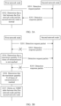
- FIG. 2 is a schematic flowchart of a communications connection detection method according to an embodiment of this application. The method includes the following steps.
- a first network node sends a detection request packet to a second network node, where the detection request packet is used to detect whether the first network node and the second network node are in a connected mode.
- the second network node After the first network node sends the detection request packet to the second network node, when receiving the detection request packet sent by the first network node, the second network node sends a detection response packet to the first network node.
- the detection response packet is a response packet in response to the detection request packet.
- the first network node deletes an NHRP table between the first network node and the second network node when the first network node determines that the first network node does not receive the detection response packet sent by the second network node, where the NHRP table is used to forward data traffic between the first network node and the second network node.
- the NHRP table between the first network node and the second network node does not automatically disappear before the NHRP table ages.
- the first network node still sends the data traffic between the first network node and the second network node based on the NHRP table, so that a transmission resource of the first network node is occupied.
- the first network node serves as a detection initiation device, and after determining that the second network node does not receive the detection request packet, deletes the NHRP table used to forward the data traffic between the first network node and the second network node. In this way, when a link fault occurs between the two nodes, it can be ensured that the data traffic is no longer sent and the transmission resource of the first network node is no longer occupied.
- the NHRP table between the first network node and the second network node is used by the first network node to forward data traffic to the second network node by using a tunnel established between the first network node and the second network node. Based on this, the first network node deletes the NHRP table between the first network node and the second network node.
- the NHRP table between the first network node and the second network node is no longer queried, so that the data traffic transmitted between the first network node and the second network node needs to be directed to a central node. This further ensures that when a fault occurs in the tunnel established between the first network node and the second network node, transmission of the data traffic between the first network node and the second network node is restored.
- the first network node when both the first network node and the second network node are branch nodes, when determining that the first network node does not receive the detection response packet sent by the second network node, the first network node deletes the NHRP table used to forward the data traffic between the first network node and the second network node.
- an aggregated routing function is restored by default after the NHRP table is deleted, where the aggregated routing function is used to forward, by using the central node, the data traffic transmitted between the first network node and the second network node.
- an aggregated routing function is not restored by default after NHRP is deleted.
- that the first network node determines that the first network node does not receive the detection response packet sent by the second network node may be implemented in the following manners:
- the first network node determines that the detection response packet sent by the second network node is not received within third preset duration. Specifically, when the detection response packet sent by the second network node is not received within the third preset duration after the first network node sends the detection request packet to the second network node, the NHRP table between the first network node and the second network node is deleted.
- the first network node determines that the detection response packet sent by the second network node is not received within third preset duration, and that after the detection request packet is repeatedly sent to the second network node for N times, the detection response packet sent by the second network node is not received. Specifically, if the detection response packet sent by the second network node is not received within the third preset duration after the first network node sends the detection request packet to the second network node, the detection request packet is resent. If the detection response packet sent by the second network node is not received after the detection request packet is repeatedly sent for N times, the first network node deletes the NHRP table between the first network node and the second network node.
- S301 or S303 may be further included.
- the second network node sends the detection response packet to the first network node when receiving the detection request packet.
- the first network node receives, within the third preset duration, the detection response packet sent by the second network node, and determines that a link between the first network node and the second network node is normal.
- the first network node does not receive, within the third preset duration, the detection response packet sent by the second network node.
- the first network node determines that a maximum quantity N of times of retransmission is not reached, and resends the detection request packet to the second network node.
- the first network node does not receive, within the third preset duration, the detection response packet sent by the second network node.
- the first network node determines that the maximum quantity N of times of retransmission is reached.
- the first network node deletes the NHRP table between the first network node and the second network node.
- the first network node is a spoke node.
- the second network node is a spoke node.
- An IP address of a subnet in which the hub is located is 192.168.1.0/24
- a public IP address (GE1/0/0) of the hub is 202.1.1.10/24
- a tunnel interface address (tunnel 0/0/0) of the hub is 172.10.1.1/24.
- An IP address of a subnet in which a spoke 1 is located is 192.168.2.0/24
- a public IP address of the spoke 1 is 202.1.2.10/24
- a tunnel interface address of the spoke 1 is 172.10.1.2/24.
- An IP address of a subnet in which a spoke 2 is located is 192.168.3.0/24
- a public IP address of the spoke 2 is 202.1.3.10/24
- a tunnel interface address of the spoke 2 is 172.10.1.3/24.
- a public IP address of each node may be considered as a non-broadcast multiple access network (Non-Broadcast Multiple Access, NBMA) address. Same as an IP address of another physical interface, a tunnel interface address is also used in communication between the nodes (for example, obtaining routing information).
- An IP address of a node in a subnet is an IP address in a local area network.
- the routing table is used to represent a correspondence between public IP addresses and tunnel interface addresses of different nodes.
- the NHRP table is used to represent an IP address of a next hop corresponding to a destination IP address of data traffic, as shown in blocks in FIG. 4 .
- the destination IP address of the data traffic is an IP address of a subnet in which a target node is located, and the IP address of the corresponding next hop is a tunnel interface address of a tunnel established between a source node and the target node on the source node. For example, for data traffic sent from the spoke 1 to the spoke 2, a destination IP address of the data traffic is 192.168.3.0, and an IP address of a corresponding next hop is 172.10.1.2.
- the first network node serves as the detection initiation device, and after determining that the detection response packet sent by the second network node is not received, deletes the NHRP table used to forward the data traffic between the first network node and the second network node, so that when a link fault occurs between the two nodes, it can be ensured that the data traffic is no longer sent and the transmission resource is no longer occupied.
- BFD bidirectional forwarding detection
- the BFD packet may be applied to link detection between spoke nodes.
- the BFD detection first requires that all spoke nodes in an entire network support and are configured with a BFD protocol.
- a BFD packet is always sent periodically, exerting pressure on the spoke nodes in the entire network and resulting in a waste of resources.
- the first network node when the first network node does not receive data traffic sent by the second network node, the first network node sends the detection request packet to the second network node.
- the first network node can determine that the link between the first network node and the second network node is normal when the data traffic transmitted by the second network node can be received. Therefore, when the first network node does not receive the data traffic transmitted by the second network node, that is, when data traffic receiving is stopped, the first network node may send the detection request package to the second network node.
- the first network node may repeatedly send the detection request packet at a preset time interval, and stop sending the detection request packet until the detection response packet sent by the second network node is received or a preset quantity of times (for example, N times) of retransmission is reached. In this way, whether the traffic between the two nodes is stopped because of a link fault can be determined in advance, thereby improving reliability of discovering the link fault. In addition, resources are saved in comparison with the prior art.
- the first network node when the first network node does not receive, within first preset duration, data traffic sent by the second network node, the first network node sends the detection request packet to the second network node.
- a reason why the first network node does not receive the data traffic sent by the second network node may be that the data traffic sent by the second network node to the first network node is transmitted completely. Therefore, the first network node may send the detection request packet to the second network node when duration in which the first network node does not receive the data traffic sent by the second network node reaches the first preset duration, that is, when duration in which data traffic receiving is stopped reaches the first preset duration.
- the first network node may repeatedly send the detection request packet at a preset time interval, and stop sending the detection request packet until the detection response packet sent by the second network node is received or a preset quantity of times (for example, N times) of retransmission is reached. In this way, whether the traffic between the two nodes is stopped because of a link fault can be determined in advance, thereby improving reliability of discovering the link fault.
- the first network node when the first network node does not receive data traffic sent by the second network node and stops sending data traffic to the second network node, the first network node sends the detection request packet to the second network node.
- the first network node does not trigger sending of the detection request packet if the first network node is sending the data traffic to the second network node, and the first network node sends the detection request packet to the second network node only when the first network node stops sending the data traffic to the second network node.
- the first network node sends the data traffic to the second network node only when the first network node does not send the data traffic to the second network node and does not receive the data traffic sent by the second network node. In comparison with the previous two possible implementations, more processing resources are saved.
- the first network node when duration in which the first network node does not receive data traffic sent by the second network node and stops sending data traffic to the second network node exceeds second preset duration, the first network node sends the detection request packet to the second network node.
- the detection request packet may be an NHRP packet.
- a new packet type may be defined and used to detect whether the first network node and the second network node are in a connected mode.
- the NHRP packet defined in this embodiment of this application may include a first field, and the first field is used to indicate that the NHRP packet is a packet used to detect whether the first network node and the second network node are in a connected mode.
- the NHRP packet defined in this embodiment of this application may further include a second field, and the second field is used by the second network node to detect whether the detection request packet is secure.
- the second field may be an authentication field in the NHRP packet.
- the first network node obtains a configured password, and generates content of the authentication field by using the configured password. Therefore, when receiving the NHRP packet, the second network node determines, based on the configured password, whether the NHRP packet is secure.
- the authentication field may be located between a packet header and a data field in the NHRP packet.
- the NHRP packet defined in this embodiment of this application may further include a third field, the third field is used to indicate a sequence number of the NHRP packet, and the sequence number is used to indicate whether the NHRP packet is a replay packet.
- Sequence numbers may be sequence numbers that increase from 1, the sequence numbers are not allowed to be duplicate, and each sequence number uniquely identifies one sent data traffic packet.
- the second network node defends against a replay packet attack based on the sequence number in combination with an anti-replay window and packet verification. For example, if the sequence number of the packet does not fall in the anti-replay window, the packet is considered as a normal packet.
- sequence number of the packet falls in the anti-replay window and falls on a right side of the anti-replay window, it is verified that the packet is a normal packet, and a right border of the anti-replay window is slid to the sequence number. If the sequence number of the packet falls on a left side of the anti-replay window, it is determined that the packet is a replay packet.
- FIG. 5 shows the NHRP packet defined in this embodiment of this application, where a "sequence number" field is the third field.
- the authentication field may be located behind the "sequence number” field shown in FIG. 5 .
- “snap” represents that the NHRP packet may use a subnetwork access protocol (subnetwork access protocol, SNAP) to encode transmitted data traffic;
- “protocol_type” represents a protocol type used by the Ethernet layer;
- hop_count represents a hop count and is used to indicate a maximum quantity of hops allowed for an NHRP data traffic packet;
- packet_size represents a size of the NHRP data traffic packet;
- checksum represents a checksum for correcting an error of an NHRP packet header;
- a source NBMA address is a public IP address of a source node;
- a source NBMA subnet address is a subnet address of the source node;
- a source protocol address is a tunnel interface address of the source node;
- a destination protocol address is a next hop address, that is, a tunnel interface address of a destination node to be detected;
- C is used to specify a function of the NHRP packet; and
- "U” is an unused
- an IPsec SA (security association) technology may be further used in a multipoint GRE tunnel network.
- the detection request packet may be the foregoing NHRP packet, or a dead peer detection (dead peer detection, DPD) packet in the IPsec SA (security association) technology may be used.
- DPD dead peer detection
- the first network node when the IPsec SA (security association) technology is used in the multipoint GRE tunnel network, in step S202, when the first network node determines that the first network node does not receive the detection response packet sent by the second network node, the first network node may further delete IP security association information, and jointly delete the NHRP table used to forward the data traffic between the first network node and the second network node.
- the IP security association information is used to encrypt the data traffic transmitted between the first network node and the second network node.
- the IP security association information is deleted in time, thereby saving storage resources of the network nodes.
- the network nodes are prevented from encrypting the data traffic based on the IP security association information, thereby saving processing resources of the network node.
- the first network node when determining that the first network node does not receive the detection response packet sent by the second network node, deletes the IP security association information and the NHRP table that is used to forward the data traffic between the first network node and the second network node. In a manner, an aggregated routing function is restored by default after the IP security association information and the NHRP table are deleted. In another manner, an aggregated routing function is not restored by default after the IP security association information and the NHRP table are deleted.
- the first network node when determining that the first network node does not receive the detection response packet sent by the second network node, determines that a fault occurs in the transmission link between the first network node and the second network node, so that the first network node may send an alarm signal to a user, where the alarm signal is used to indicate that a fault occurs in the transmission link between the first network node and the second network node.
- the alarm signal may be a warning sound (for example, a buzzing sound or an alarm) that can be heard by the user, may be a warning (for example, illumination light, flashing light, an image on a display, or prompt text on a display) that can be seen by the user, or may be an alarm (for example, vibration) that can be touched by the user.
- a warning sound for example, a buzzing sound or an alarm
- a warning for example, illumination light, flashing light, an image on a display, or prompt text on a display
- an alarm for example, vibration
- the first network node if the first network node receives a detection request packet sent by the second network node, the first network node sends a detection response packet to the second network node, so that the second network node determines that the link between the first network node and the second network node is normal.
- an embodiment of this application provides a communications connection detection apparatus.
- the apparatus may be applied to a first network node in a multipoint generic routing encapsulation protocol GRE tunnel network, and the apparatus is specifically configured to implement the method performed by the first network node in the embodiments shown in FIG. 2 to FIG. 5 .
- the apparatus may include:
- the apparatus may further include:
- the apparatus may further include: when determining that the first receiving module 65 does not receive the detection response packet sent by the second network node, the processing module 62 is specifically configured to:
- the detection request packet is an NHRP packet
- the NHRP packet includes a first field
- the first field is used to indicate that the NHRP packet is a packet used to detect whether the first network node and the second network node are in a connected mode.
- the NHRP packet further includes a second field, and the second field is used by the second network node to detect whether the detection request packet is secure.
- the NHRP packet further includes a third field, the third field is used to indicate a sequence number of the NHRP packet, and the sequence number is used to indicate whether the NHRP packet is a replay packet.
- the detection request packet is a DPD packet.
- the processing module 62 is further configured to delete IP security association information when determining that the first receiving module 65 does not receive the detection response packet sent by the second network node, where the IP security association information is used to encrypt the data traffic transmitted between the first network node and the second network node.
- the processing module 62 is further configured to restore an aggregated routing function between the first network node and the central node when determining that the first receiving module 65 does not receive the detection response packet sent by the second network node, where the aggregated routing function is used by the processing module 62 to forward, by using the central node, the data traffic transmitted between the first network node and the second network node.
- the processing module 62 is further configured to send an alarm signal when determining that the first receiving module 65 does not receive the detection response packet sent by the second network node, where the alarm signal is used to indicate that a fault occurs in a transmission link between the first network node and the second network node.
- Module division in the embodiments of this application is an example, is merely logical function division, and may be another division in actual implementation.
- functional modules in the embodiments of this application may be integrated into one or more processors, or each of the modules may exist alone physically, or two or more modules may be integrated into one module.
- the integrated module may be implemented in a form of hardware, or may be implemented in a form of a software functional module. Therefore, the method in any of the foregoing embodiments of this application may be implemented by one or more processors in the first network node.
- the first network node described herein is a branch node.
- a structure of the first network node is the same as that of the second network node. For the structure of the second network node, refer to the first network node. Details are not described again.
- the first network node When implemented by using hardware, the first network node may be implemented by using a structure shown in FIG. 7 , or may be implemented by using a structure shown in FIG. 8 .
- FIG. 7 is a schematic structural diagram of a first network node according to an embodiment of this application.
- the first network node may include a main control board 510, a switching board 520, an interface board 530, and an interface board 540.
- the main control board 510 includes a central processing unit 511.
- the interface board 530 includes a memory 534, a network processor 532, and a physical interface card 533.
- the interface board 540 includes a memory 544, a network processor 542, and a physical interface card 543.
- the switching network board 520 is mainly configured to forward a data traffic packet between the interface board 530 and the interface board 540.
- the interface board 530 serves as a receiving board
- the interface board 540 serves as a sending board.
- the network processor 532 When detecting, based on a detection interval (first preset duration) configured by an operation manager (operation manager, OM), that data traffic sent by a second network node is not received in the configured time interval, the network processor 532 considers that the traffic is abnormal, and sends a detection request message to the central processing unit 511.
- a detection interval first preset duration
- operation manager operation manager
- the central processing unit 511 After receiving the detection request message, the central processing unit 511 constructs a detection request packet, queries a local routing table according to a destination address of the detection request packet to find the interface board 530 on which an outbound interface is located, and then delivers the detection request packet to the network processor 532.
- the network processor 532 sends, based on information such as the outbound interface, the detection request packet by using the physical interface card 533 after completing link layer encapsulation, that is, sends the detection request packet to the second network node.
- the physical interface card 543 After receiving, from a network, a detection response packet sent by the second network node, the physical interface card 543 sends the detection response packet to the network processor 542.
- the physical interface card 543 receives the detection response packet from the network, and after completing related verification, submits the detection response packet to the network processor 542 for processing.
- the network processor 542 queries, by using a destination address of the detection response packet, an NHRP table stored in the memory 544; determines that the detection response packet is a local packet; and sends the detection response packet to the central processing unit 511 for processing.
- the central processing unit 511 performs matching with the detection request packet based on information such as a detection address and a sequence number carried in the received detection response packet. If the matching succeeds, it is considered that a link state is normal. If the central processing unit 511 does not receive, within third preset duration, the detection response packet sent by the second network node, the detection request packet is retransmitted for limited times.
- the link may be set to DOWN, and NHRP tables stored in the memory 544 and the memory 534 and used to forward data traffic between the first network node and the second network node are deleted.
- the physical interface card 543 receives, from the network, a detection request packet sent by the second network node, and submits the detection request packet to the network processor 542 for processing.
- the network processor 542 queries a local route by using a destination address of the detection request packet, determines that the detection request packet is a local packet, and sends the detection request packet to the central processing unit 511 for processing.
- the central processing unit 511 After performing verification according to packet characteristic information of the received detection request packet, the central processing unit 511 determines that the detection request packet is a packet used to detect whether the first network node and the second network node is in a connected mode, and constructs a detection response packet. The central processing unit 511 queries, based on a destination address of the detection response packet, the NHRP table stored in the memory 534, to find the interface board 530 on which the outbound interface is located; and then delivers the detection response packet the network processor 532.
- the network processor 532 sends, based on information such as the outbound interface, the detection response packet by using the physical interface card 533 after completing link layer encapsulation, that is, sends the detection response packet to the second network node.
- FIG. 8 is a schematic structural diagram of another first network node according to an embodiment of this application.
- the first network node includes a communications interface 610, a processor 620, and a memory 630.
- the processor 620 receives and sends data traffic, a detection request packet, and a detection response packet by using the transceiver 610, and is configured to implement the method executed by the first network node in FIG. 2 to FIG. 4 .
- steps in a processing procedure may be completed by using a hardware integrated logic circuit in the processor 620 or an instruction in a form of software.
- the processor 620 includes one or more of a general purpose processor, a network processor, a digital signal processor, an application-specific integrated circuit, a field programmable gate array or another programmable logic device, a discrete gate or a transistor logic device, a discrete hardware component, or the like, and may implement or execute the methods, steps, and logical block diagrams disclosed in the embodiments of this application.
- the general purpose processor may be a microprocessor or any conventional processor or the like.
- the steps of the method disclosed with reference to the embodiments of this application may be directly performed by a hardware processor, or may be performed by using a combination of hardware in the processor and a software unit.
- Program code executed by the processor 620 to implement the foregoing method may be stored in the memory 630.
- the memory 630 may be a nonvolatile memory such as a hard disk drive (English: hard disk drive, HDD for short) or a solid state drive (English: solid-state drive, SSD for short), or may be a volatile memory (English: volatile memory) such as a random access memory (English: random-access memory, RAM for short).
- the memory 630 is any other medium that can be configured to carry or store expected program code in a form of an instruction or a data structure and that can be accessed by a computer, without being limited thereto.
- a specific connection medium between the transceiver 610, the processor 620, and the memory 630 is not limited.
- the memory 630, the processor 620, and the transceiver 610 are connected by using a bus 640 in FIG. 8 .
- the bus is represented by using a bold line in FIG. 8 .
- a manner of connection between other components is merely an example for description, and imposes no limitation.
- the bus may be classified into an address bus, a data bus, a control bus, and the like. For ease of representation, only one bold line is used to represent the bus in FIG. 8 , but this does not mean that there is only one bus or only one type of bus.
- an embodiment of this application further provides a computer storage medium.
- the storage medium stores a software program, and when the software program is read and executed by one or more processors, the method provided in the foregoing embodiments may be implemented.
- the computer storage medium may include: any medium that can store program code, such as a USB flash drive, a removable hard disk, a read-only memory, a random access memory, a magnetic disk, or an optical disc.
- an embodiment of this application further provides a chip system.
- the chip system includes a processor, configured to support a distributed unit, a centralized unit, and a base station in implementing a function in the foregoing embodiments, for example, generating or processing data and/or information in the foregoing method.
- the chip system further includes a memory, and the memory is configured to store a program instruction and data that are necessary for the distributed unit, the centralized unit, and a network node.
- the chip system may include a chip, or may include a chip and another discrete device.
- this application may be provided as a method, a system, or a computer program product. Therefore, this application may use a form of hardware only embodiments, software only embodiments, or embodiments with a combination of software and hardware. Moreover, this application may use a form of a computer program product that is implemented on one or more computer-usable storage media (including but not limited to a disk memory, a CD-ROM, an optical memory, and the like) that include computer usable program code.
- a computer-usable storage media including but not limited to a disk memory, a CD-ROM, an optical memory, and the like
- These computer program instructions may be provided for a general-purpose computer, a dedicated computer, an embedded processor, or a processor of any other programmable data processing device to generate a machine, so that the instructions executed by a computer or a processor of any other programmable data processing device generate an apparatus for implementing a specific function in one or more processes in the flowcharts and/or in one or more blocks in the block diagrams.
- These computer program instructions may be stored in a computer readable memory that can instruct the computer or any other programmable data processing device to work in a specific manner, so that the instructions stored in the computer readable memory generate an artifact that includes an instruction apparatus.
- the instruction apparatus implements a specific function in one or more processes in the flowcharts and/or in one or more blocks in the block diagrams.
- These computer program instructions may be loaded onto a computer or another programmable data processing device, so that a series of operations and steps are performed on the computer or the another programmable device, thereby generating computer-implemented processing. Therefore, the instructions executed on the computer or the another programmable device provide steps for implementing a specific function in one or more processes in the flowcharts and/or in one or more blocks in the block diagrams.
Landscapes
- Engineering & Computer Science (AREA)
- Computer Networks & Wireless Communication (AREA)
- Signal Processing (AREA)
- Environmental & Geological Engineering (AREA)
- Data Exchanges In Wide-Area Networks (AREA)
Description
- This application relates to the field of information technologies, and in particular, to a communications connection detection method and apparatus.
- Cisco: "SCALABLE DMVPN DESIGN AND IMPLEMENTATION GUIDE", 31 December 2007 (2007-12-31), XP055520802 describes three Dynamic Multipoint Virtual Private Network (DMVPN) core topology designs, wherein as the scale increases handling of routing information and Next Hop Resolution Protocol (NHRP) tables is considered. Further, regarding a hierarchical hub DMVPN design, an option using Dead Peer Detection (DPD) on hubs and spokes is applied to increase stability of the design.
-
CN 102 355 416 A relates to a method for establishing a route by linking routing information protocol (RIP) with bidirectional forwarding detection (BFD). By adopting the method, the phenomenon that an RIP route cannot be deleted or is oscillated in case of single-pass of a link can be avoided. - An auto discovery virtual private network (auto discovery virtual private network, ADVPN) allows a hub (hub) node as a central node to use a static Internet protocol (Internet Protocol, IP) address, and a router (spoke) node as a branch node may use a dynamic IP address. The hub node establishes a static tunnel with each spoke node by using a multipoint generic routing encapsulation protocol (multipoint generic routing encapsulation, MGRE) interface. Data traffic between spokes may be transmitted by using a dynamic tunnel established between the spokes, and does not need to be forwarded by a hub, thereby reducing overheads of the hub node.
- The dynamic tunnels between the spoke nodes may be established by using a next hop resolution protocol (next hop resolution protocol, NHRP). The NHRP protocol is used to resolve a problem of how a source spoke node obtains a dynamic public IP address of a destination spoke node.
- An existing solution only resolves a keepalive problem between the spoke node and the hub node. However, in the prior art, there is no effective way to resolve a problem of how to restore the data traffic between the spoke nodes after a link between the spoke nodes is interrupted.
- This application provides a communications connection detection method and apparatus, to provide an effective way to restore transmission of data traffic between spoke nodes.
- According to a first aspect, an embodiment of the invention provides a communications connection detection method, according to
claim 1, including: sending, by a first network node, a detection request packet to a second network node, where the detection request packet is used to detect whether the first network node and the second network node are in a connected mode; and deleting, by the first network node, an NHRP table when the first network node determines that the first network node does not receive a detection response packet sent by the second network node, where the detection response packet is a response packet in response to the detection request packet, and the NHRP table is used to forward data traffic between the first network node and the second network node. - Currently, when a link fault occurs between the two nodes, the NHRP table between the first network node and the second network node does not automatically disappear before the NHRP table ages. Before the NHRP table ages, the first network node still sends the data traffic between the first network node and the second network node based on the NHRP table, so that a transmission resource of the first network node is occupied. According to the manner provided in this embodiment of this application, the first network node serves as a detection initiation device, and after determining that the first network node does not receive the detection response packet sent by the second network node, deletes the NHRP table used to forward the data traffic between the first network node and the second network node. In this way, when a link fault occurs between the two nodes, it can be ensured that the data traffic is no longer sent and the transmission resource is no longer occupied.
- In this embodiment of this application, when both the first network node and the second network node are branch nodes, after the first network node deletes the NHRP table between the first network node and the second network node, the NHRP table is no longer queried, and the data traffic transmitted between the first network node and the second network node is forwarded by a central node, where the NHRP table is used by the first network node to forward data traffic to the second network node by using a tunnel established between the first network node and the second network node. In this way, after a fault occurs in the tunnel established between the first network node and the second network node, transmission of the data traffic between the first network node and the second network node is restored. Therein, the first network node and the second network node are spoke nodes and the central node is a hub node.
- The foregoing method may be applied without being limited to a multipoint generic routing encapsulation protocol GRE tunnel network. Certainly, other networking modes in which NHRP can be applied are all applicable to this embodiment of this application.
- In a possible design, when the first network node does not receive data traffic sent by the second network node, the first network node sends the detection request packet to the second network node. When the first network node can receive the data traffic transmitted by the second network node, it can be determined that the link between the first network node and the second network node is normal. Therefore, when the first network node does not receive the data traffic transmitted by the second network node, that is, when data traffic receiving is stopped, the first network node may send the detection request package to the second network node. In this way, whether the traffic between the two nodes is stopped because of a link fault can be determined in advance, thereby improving reliability of discovering the link fault.
- In a possible implementation, when the first network node does not receive, within first preset duration, data traffic sent by the second network node, the first network node sends the detection request packet to the second network node. A reason why the first network node does not receive the data traffic sent by the second network node may be that the data traffic sent by the second network node to the first network node is transmitted completely. Therefore, the first network node may send the detection request packet to the second network node when duration in which the first network node does not receive the data traffic sent by the second network node reaches the first preset duration, that is, when duration in which data traffic receiving is stopped reaches the first preset duration. In this way, whether the traffic between the two nodes is stopped because of a link fault can be determined in advance, thereby improving reliability of discovering the link fault.
- In a possible design, when the first network node does not receive data traffic sent by the second network node and stops sending data traffic to the second network node, the first network node sends the detection request packet to the second network node. When the first network node does not receive the data traffic sent by the second network node, the first network node does not trigger sending of the detection request packet if the first network node is sending the data traffic to the second network node, and the first network node sends the detection request packet to the second network node only when the first network node stops sending the data traffic to the second network node. In other words, the first network node sends the detection request packet to the second network node only when the first network node does not send the data traffic to the second network node and does not receive the data traffic sent by the second network node.
- In a possible design, when duration in which the first network node does not receive data traffic sent by the second network node and stops sending data traffic to the second network node exceeds second preset duration, the first network node sends the detection request packet to the second network node.
- In a possible design, that the first network node determines that the first network node does not receive a detection response packet sent by the second network node includes:
determining, by the first network node, that the detection response packet sent by the second network node is not received within third preset duration; or determining, by the first network node, that the detection response packet sent by the second network node is not received within third preset duration, and that the detection response packet sent by the second network node is not received after the detection request packet is repeatedly sent to the second network node for N times, where N is an integer greater than 1. - The foregoing design provides two simple and effective manners for determining that the first network node does not receive the detection response packet sent by the second network node.
- In a possible design, the detection request packet is an NHRP packet, the NHRP packet includes a first field, and the first field is used to indicate that the NHRP packet is a packet used to detect whether the first network node and the second network node are in a connected mode.
- In the foregoing design, a protocol packet existing in a multipoint GRE tunnel network, that is, an NHRP protocol packet, is used, without a need to configure another detection packet, such as BFD, for each node in the network, thereby saving resources of the nodes.
- In a possible design, the NHRP packet further includes a second field, and the second field is used by the second network node to detect whether the detection request packet is secure. This improves security of the detection request packet, thereby improving link security.
- In a possible design, the NHRP packet further includes a third field, the third field is used to indicate a sequence number of the NHRP packet, and the sequence number is used to indicate whether the NHRP packet is a replay packet. This protects, to some extent, the network node from being attacked.
- In a possible design, the detection request packet is a dead peer detection DPD packet. An IP security association technology is used in a multipoint GRE tunnel network. Therefore, a DPD packet of the IP security association technology is used, without a need to configure another detection packet, such as BFD, for each node in the network, thereby saving resources of the nodes.
- In a possible design, when the first network node determines that the first network node does not receive the detection response packet sent by the second network node, the method further includes: deleting, by the first network node, IP security association information, where the IP security association information is used to encrypt the data traffic transmitted between the first network node and the second network node.
- In the foregoing design, when a fault occurs in a transmission link between the first network node and the second network node, the IP security association information is deleted in time, thereby saving storage resources of the nodes.
- In a possible design, when the first network node determines that the first network node does not receive the detection response packet sent by the second network node, the first network node deletes the NHRP table between the first network node and the second network node, and the first network node restores an aggregated routing function between the first network node and the central node, where the aggregated routing function is used to forward, by using the central node, the data traffic transmitted between the first network node and the second network node.
- According to the foregoing design, after a link fault occurs between the two branch nodes, forwarding by the central node may be restored, thereby restoring transmission of the data traffic between the branch nodes.
- In a possible design, when the first network node determines that the first network node does not receive the detection response packet sent by the second network node, the method further includes: sending, by the first network node, an alarm signal, where the alarm signal is used to indicate that a fault occurs in the transmission link between the first network node and the second network node.
- According to the foregoing design, when a fault occurs in the transmission link between the first network node and the second network node, a user may be reminded, so that the user can repair the link fault in time.
- According to a second aspect, based on a same inventive concept as the foregoing embodiment of the first aspect, an embodiment of the invention provides a communications connection detection apparatus, according to
claim 9, where the apparatus is applied to a first network node, and includes: - a first sending module, configured to send a detection request packet to a second network node, where the detection request packet is used to detect whether the first network node and the second network node are in a connected mode;
- a first receiving module, configured to receive a detection response packet sent by the second network node; and
- a processing module, configured to delete, by the first network node, an NHRP table when determining that the first receiving module does not receive the detection response packet sent by the second network node, so that data traffic transmitted between the first network node and the second network node is forwarded by a central node, where the NHRP table is used by the first network node to forward data traffic to the second network node by using a tunnel established between the first network node and the second network node. Therein, the first network node and the second network node are spoke nodes and the central node is a hub node.
- In the foregoing manner, the first network node serves as a detection initiation device, and after determining that the second network node does not receive the detection request packet, deletes the NHRP table used to forward the data traffic between the first network node and the second network node. In this way, when a link fault occurs between the two nodes, it can be ensured that the data traffic is no longer sent and a transmission resource is no longer occupied.
- In a possible design, the apparatus further includes:
- a second receiving module, configured to receive data traffic sent by the second network node; and
- a second sending module, configured to send data traffic to the second network node, where
- the first sending module is specifically configured to send the detection request packet to the second network node when it is determined that any one of the following conditions is met:
- the second receiving module does not receive the data traffic sent by the second network node;
- the second receiving module does not receive, within first preset duration, the data traffic sent by the second network node;
- the second receiving module does not receive the data traffic sent by the second network node, and the second sending module does not send the data traffic to the second network node; or
- duration in which the second receiving module does not receive the data traffic sent by the second network node and the second sending module does not send the data traffic to the second network node exceeds second preset duration.
- According to the foregoing design, reliability of discovering the link fault can be improved.
- In a possible design, when determining that the first receiving module does not receive the detection response packet sent by the second network node, the processing module is specifically configured to:
- determine that the first receiving module does not receive, within third preset duration, the detection response packet sent by the second network node; or
- determine that the first receiving module does not receive, within third preset duration, the detection response packet sent by the second network node, and that after the first sending module repeatedly sends the detection request packet to the second network node for N times, the first receiving module does not receive the detection response packet sent by the second network node, where N is an integer greater than 1.
- The foregoing design provides two simple and effective manners for determining that the first receiving module does not receive the detection response packet sent by the second network node.
- In a possible design, the detection request packet is an NHRP packet, the NHRP packet includes a first field, and the first field is used to indicate that the NHRP packet is a packet used to detect whether the first network node and the second network node are in a connected mode. In the foregoing design, a protocol packet existing in a multipoint GRE tunnel network, that is, an NHRP protocol packet, is used, without a need to configure another detection packet, such as BFD, for each node in the network, thereby saving resources of the nodes.
- In a possible design, the NHRP packet further includes a second field, and the second field is used by the network node to detect whether the detection request packet is secure. This improves security of the detection request packet, thereby improving link security.
- In a possible design, the NHRP packet further includes a third field, the third field is used to indicate a sequence number of the NHRP packet, and the sequence number is used to indicate whether the NHRP packet is a replay packet. This protects, to some extent, the network node from being attacked.
- In a possible design, the detection request packet is a dead peer detection DPD packet. An IP security association technology is used in a multipoint GRE tunnel network. Therefore, a DPD packet of the IP security association technology is used, without a need to configure another detection packet, such as BFD, for each node in the network, thereby saving resources of the nodes.
- In a possible design, the processing module is further configured to delete IP security association information when determining that the first receiving module does not receive the detection response packet sent by the second network node, where the IP security association information is used to encrypt the data traffic transmitted between the first network node and the second network node. In the foregoing design, when a fault occurs in a transmission link between the first network node and the second network node, the IP security association information is deleted in time, thereby saving storage resources of the nodes.
- In a possible design, the processing module is further configured to restore an aggregated routing function between the first network node and the central node when determining that the first receiving module does not receive the detection response packet sent by the second network node, where the aggregated routing function is used by the processing module to forward, by using the central node, the data traffic transmitted between the first network node and the second network node. According to the foregoing design, after a link fault occurs between the two branch nodes, forwarding by the central node may be restored, thereby restoring transmission of the data traffic between the branch nodes.
- In a possible design, the processing module is further configured to send an alarm signal when determining that the first receiving module does not receive the detection response packet sent by the second network node, where the alarm signal is used to indicate that a fault occurs in the transmission link between the first network node and the second network node. According to the foregoing design, when a fault occurs in the transmission link between the first network node and the second network node, a user may be reminded, so that the user can repair the link fault in time.
- According to a third aspect, an embodiment of this application provides a communications connection detection network node, including a communications interface, a memory, and a processor, where
- the communications interface is configured to send and receive data;
- the memory is configured to store a program executed by the processor; and
- the processor is configured to execute the program stored in the memory, and send and receive data by using the communications interface, to implement the method according to any design of the first aspect.
- According to a fourth aspect, an embodiment of this application provides a computer storage medium, where the computer readable storage medium stores a computer executable instruction, and the computer executable instruction is used to enable the computer to execute the method according to any design of the first aspect.
- According to a fifth aspect, an embodiment of this application provides a chip, where the chip is connected to a memory, and is configured to read and execute a software program stored in the memory, to implement the method according to any design of the first aspect.
-
-
FIG. 1 is an architectural diagram of a multipoint GRE tunnel network according to an embodiment of this application; -
FIG. 2 is a flowchart of a communications connection detection method according to an embodiment of this application; -
FIG. 3A is a schematic flowchart of a communications connection detection method according to an embodiment of this application; -
FIG. 3B is a schematic flowchart of another communications connection detection method according to an embodiment of this application; -
FIG. 4 is a schematic diagram of an NHRP table according to an embodiment of this application; -
FIG. 5 is a schematic diagram of an NHRP packet according to an embodiment of this application; -
FIG. 6 is a schematic structural diagram of a communications connection detection apparatus according to an embodiment of this application; -
FIG. 7 is a schematic structural diagram of a first network node according to an embodiment of this application; and -
FIG. 8 is a schematic structural diagram of another first network node according to an embodiment of this application. - Embodiments of the invention propose a communications connection detection method and apparatus. When a tunnel established between a first network node and a second network node is faulty, an NHRP table is deleted, so that when a link fault occurs between the two nodes, it can be ensured that data traffic is no longer sent and a transmission resource is no longer occupied. Further, forwarding, by a central node, of data traffic transmitted between the first network node and the second network node may be triggered, thereby restoring transmission of the data traffic between the first network node and the second network node. The method and the apparatus are based on a same inventive concept. The method and the apparatus have similar problem-resolving principles. Therefore, for implementations of the apparatus and the method, reference may be made to each other. Details are not described repeatedly.
- The communications connection detection method and apparatus proposed in the embodiments of this application may be applied without being limited to a multipoint GRE tunnel network, and other networking modes in which an NHRP protocol can be applied are all applicable to this application. In the embodiments of this application, that the communications connection detection method and apparatus are applied to the multipoint GRE tunnel network is used as an example for description. The multipoint GRE tunnel network includes one central node and a plurality of branch nodes. As shown in
FIG. 1 , a multipoint GRE tunnel network includes one central node, for example, a hub node inFIG. 1 , and further includes two branch nodes, for example, aspoke 1 and aspoke 2 inFIG. 1 . A hub-spoke tunnel is established between the hub node and each of the two spoke nodes, and a spoke-spoke tunnel is established between thespoke 1 and thespoke 2 based on the NHRP protocol. Data traffic between thespoke 1 and thespoke 2 may be transmitted by using the spoke-spoke tunnel. - A network node mentioned in the embodiments of this application may be a central node or may be a branch node. "A plurality of" mentioned in the embodiments of this application means two or more.
- In addition, it should be understood that, in the description of this application, terms such as "first" and "second" are used only for distinguishing between descriptions, but cannot be understood as an indication or implication of relative importance, and cannot be understood as an indication or implication of a sequence.
- To make the objectives, technical solutions, and advantages of this application clearer, the following further describes this application in detail with reference to the accompanying drawings.
-
FIG. 2 is a schematic flowchart of a communications connection detection method according to an embodiment of this application. The method includes the following steps. - S201. A first network node sends a detection request packet to a second network node, where the detection request packet is used to detect whether the first network node and the second network node are in a connected mode. After the first network node sends the detection request packet to the second network node, when receiving the detection request packet sent by the first network node, the second network node sends a detection response packet to the first network node. The detection response packet is a response packet in response to the detection request packet.
- S202. The first network node deletes an NHRP table between the first network node and the second network node when the first network node determines that the first network node does not receive the detection response packet sent by the second network node, where the NHRP table is used to forward data traffic between the first network node and the second network node.
- Currently, when a link fault occurs between the two nodes, the NHRP table between the first network node and the second network node does not automatically disappear before the NHRP table ages. Before the NHRP table ages, the first network node still sends the data traffic between the first network node and the second network node based on the NHRP table, so that a transmission resource of the first network node is occupied. According to the manner provided in this embodiment of this application, the first network node serves as a detection initiation device, and after determining that the second network node does not receive the detection request packet, deletes the NHRP table used to forward the data traffic between the first network node and the second network node. In this way, when a link fault occurs between the two nodes, it can be ensured that the data traffic is no longer sent and the transmission resource of the first network node is no longer occupied.
- In this embodiment of this application, when both the first network node and the second network node are branch nodes, the NHRP table between the first network node and the second network node is used by the first network node to forward data traffic to the second network node by using a tunnel established between the first network node and the second network node. Based on this, the first network node deletes the NHRP table between the first network node and the second network node. In other words, when the first network node determines that the data traffic needs to be sent to the second network node, the NHRP table between the first network node and the second network node is no longer queried, so that the data traffic transmitted between the first network node and the second network node needs to be directed to a central node. This further ensures that when a fault occurs in the tunnel established between the first network node and the second network node, transmission of the data traffic between the first network node and the second network node is restored.
- In this embodiment of this application, when both the first network node and the second network node are branch nodes, when determining that the first network node does not receive the detection response packet sent by the second network node, the first network node deletes the NHRP table used to forward the data traffic between the first network node and the second network node. In a first manner, an aggregated routing function is restored by default after the NHRP table is deleted, where the aggregated routing function is used to forward, by using the central node, the data traffic transmitted between the first network node and the second network node. In a second manner, an aggregated routing function is not restored by default after NHRP is deleted. In the second manner, after the first network node deletes the NHRP table used to forward the data traffic between the first network node and the second network node, an aggregated routing function between the first network node and the central node is restored. In this way, after a link fault occurs between the two branch nodes, forwarding by the central node may be restored, thereby restoring transmission of the data traffic between the branch nodes.
- In this embodiment of this application, that the first network node determines that the first network node does not receive the detection response packet sent by the second network node may be implemented in the following manners:
- The first network node determines that the detection response packet sent by the second network node is not received within third preset duration. Specifically, when the detection response packet sent by the second network node is not received within the third preset duration after the first network node sends the detection request packet to the second network node, the NHRP table between the first network node and the second network node is deleted.
- The first network node determines that the detection response packet sent by the second network node is not received within third preset duration, and that after the detection request packet is repeatedly sent to the second network node for N times, the detection response packet sent by the second network node is not received. Specifically, if the detection response packet sent by the second network node is not received within the third preset duration after the first network node sends the detection request packet to the second network node, the detection request packet is resent. If the detection response packet sent by the second network node is not received after the detection request packet is repeatedly sent for N times, the first network node deletes the NHRP table between the first network node and the second network node.
- Specifically, refer to
FIG. 3A or FIG. 3B . After S201 in which the first network node sends the detection request packet to the second network node, S301 or S303 may be further included. - S301. The second network node sends the detection response packet to the first network node when receiving the detection request packet.
- S302. The first network node receives, within the third preset duration, the detection response packet sent by the second network node, and determines that a link between the first network node and the second network node is normal.
- S303. The first network node does not receive, within the third preset duration, the detection response packet sent by the second network node.
- S304. The first network node determines that a maximum quantity N of times of retransmission is not reached, and resends the detection request packet to the second network node.
- S305. The first network node does not receive, within the third preset duration, the detection response packet sent by the second network node.
- S306. The first network node determines that the maximum quantity N of times of retransmission is reached.
- S307. The first network node deletes the NHRP table between the first network node and the second network node.
- The first network node is a spoke node. The second network node is a spoke node.
- For example, as shown in
FIG. 4 , when a multipoint GRE tunnel network is established, two spokes and a hub learn of an NHRP table and a routing table by using an NHRP protocol. - An IP address of a subnet in which the hub is located is 192.168.1.0/24, a public IP address (GE1/0/0) of the hub is 202.1.1.10/24, and a tunnel interface address (
tunnel 0/0/0) of the hub is 172.10.1.1/24. An IP address of a subnet in which aspoke 1 is located is 192.168.2.0/24, a public IP address of thespoke 1 is 202.1.2.10/24, and a tunnel interface address of thespoke 1 is 172.10.1.2/24. An IP address of a subnet in which aspoke 2 is located is 192.168.3.0/24, a public IP address of thespoke 2 is 202.1.3.10/24, and a tunnel interface address of thespoke 2 is 172.10.1.3/24. - A public IP address of each node may be considered as a non-broadcast multiple access network (Non-Broadcast Multiple Access, NBMA) address. Same as an IP address of another physical interface, a tunnel interface address is also used in communication between the nodes (for example, obtaining routing information). An IP address of a node in a subnet is an IP address in a local area network.
- The routing table is used to represent a correspondence between public IP addresses and tunnel interface addresses of different nodes. The NHRP table is used to represent an IP address of a next hop corresponding to a destination IP address of data traffic, as shown in blocks in
FIG. 4 . The destination IP address of the data traffic is an IP address of a subnet in which a target node is located, and the IP address of the corresponding next hop is a tunnel interface address of a tunnel established between a source node and the target node on the source node. For example, for data traffic sent from thespoke 1 to thespoke 2, a destination IP address of the data traffic is 192.168.3.0, and an IP address of a corresponding next hop is 172.10.1.2. Currently, if a link fault occurs between thespoke 1 and thespoke 2, an NHRP table between thespoke 1 and thespoke 2 does not automatically disappear before the NHRP table ages. Before the NHRP table ages, traffic to be sent from thespoke 1 to thespoke 2 is still sent after the NHRP table is queried, so that a transmission resource of thespoke 1 is occupied. - Therefore, according to the solution provided in this embodiment of this application, the first network node serves as the detection initiation device, and after determining that the detection response packet sent by the second network node is not received, deletes the NHRP table used to forward the data traffic between the first network node and the second network node, so that when a link fault occurs between the two nodes, it can be ensured that the data traffic is no longer sent and the transmission resource is no longer occupied.
- In the prior art, keepalive between a spoke node and a hub node is implemented by using a bidirectional forwarding detection (bidirectional forwarding detection, BFD) packet. BFD is a conventional link detection method. The BFD packet may be applied to link detection between spoke nodes. The BFD detection first requires that all spoke nodes in an entire network support and are configured with a BFD protocol. However, in an asynchronous mode of the BFD protocol, a BFD packet is always sent periodically, exerting pressure on the spoke nodes in the entire network and resulting in a waste of resources.
- In a possible implementation, when the first network node does not receive data traffic sent by the second network node, the first network node sends the detection request packet to the second network node. The first network node can determine that the link between the first network node and the second network node is normal when the data traffic transmitted by the second network node can be received. Therefore, when the first network node does not receive the data traffic transmitted by the second network node, that is, when data traffic receiving is stopped, the first network node may send the detection request package to the second network node. The first network node may repeatedly send the detection request packet at a preset time interval, and stop sending the detection request packet until the detection response packet sent by the second network node is received or a preset quantity of times (for example, N times) of retransmission is reached. In this way, whether the traffic between the two nodes is stopped because of a link fault can be determined in advance, thereby improving reliability of discovering the link fault. In addition, resources are saved in comparison with the prior art.
- In another possible implementation, when the first network node does not receive, within first preset duration, data traffic sent by the second network node, the first network node sends the detection request packet to the second network node. A reason why the first network node does not receive the data traffic sent by the second network node may be that the data traffic sent by the second network node to the first network node is transmitted completely. Therefore, the first network node may send the detection request packet to the second network node when duration in which the first network node does not receive the data traffic sent by the second network node reaches the first preset duration, that is, when duration in which data traffic receiving is stopped reaches the first preset duration. The first network node may repeatedly send the detection request packet at a preset time interval, and stop sending the detection request packet until the detection response packet sent by the second network node is received or a preset quantity of times (for example, N times) of retransmission is reached. In this way, whether the traffic between the two nodes is stopped because of a link fault can be determined in advance, thereby improving reliability of discovering the link fault.
- In still another possible implementation, when the first network node does not receive data traffic sent by the second network node and stops sending data traffic to the second network node, the first network node sends the detection request packet to the second network node. When the first network node does not receive the data traffic sent by the second network node, the first network node does not trigger sending of the detection request packet if the first network node is sending the data traffic to the second network node, and the first network node sends the detection request packet to the second network node only when the first network node stops sending the data traffic to the second network node. In other words, the first network node sends the data traffic to the second network node only when the first network node does not send the data traffic to the second network node and does not receive the data traffic sent by the second network node. In comparison with the previous two possible implementations, more processing resources are saved.
- In still another possible implementation, when duration in which the first network node does not receive data traffic sent by the second network node and stops sending data traffic to the second network node exceeds second preset duration, the first network node sends the detection request packet to the second network node.
- In this embodiment of this application, the detection request packet may be an NHRP packet. Specifically, in this embodiment of this application, on a basis of an NHRP standard packet, a new packet type may be defined and used to detect whether the first network node and the second network node are in a connected mode.
- The NHRP packet defined in this embodiment of this application may include a first field, and the first field is used to indicate that the NHRP packet is a packet used to detect whether the first network node and the second network node are in a connected mode. Refer to a field "type=10" shown in
FIG. 5 . When extension type=10, it indicates that the packet is a packet for detecting whether the first network node and the second network node are in a connected mode. - The NHRP packet defined in this embodiment of this application may further include a second field, and the second field is used by the second network node to detect whether the detection request packet is secure. The second field may be an authentication field in the NHRP packet. The first network node obtains a configured password, and generates content of the authentication field by using the configured password. Therefore, when receiving the NHRP packet, the second network node determines, based on the configured password, whether the NHRP packet is secure. The authentication field may be located between a packet header and a data field in the NHRP packet.
- The NHRP packet defined in this embodiment of this application may further include a third field, the third field is used to indicate a sequence number of the NHRP packet, and the sequence number is used to indicate whether the NHRP packet is a replay packet. Sequence numbers may be sequence numbers that increase from 1, the sequence numbers are not allowed to be duplicate, and each sequence number uniquely identifies one sent data traffic packet. The second network node defends against a replay packet attack based on the sequence number in combination with an anti-replay window and packet verification. For example, if the sequence number of the packet does not fall in the anti-replay window, the packet is considered as a normal packet. If the sequence number of the packet falls in the anti-replay window and falls on a right side of the anti-replay window, it is verified that the packet is a normal packet, and a right border of the anti-replay window is slid to the sequence number. If the sequence number of the packet falls on a left side of the anti-replay window, it is determined that the packet is a replay packet.
-
FIG. 5 shows the NHRP packet defined in this embodiment of this application, where a "sequence number" field is the third field. The authentication field may be located behind the "sequence number" field shown inFIG. 5 . - In
FIG. 5 , "snap" represents that the NHRP packet may use a subnetwork access protocol (subnetwork access protocol, SNAP) to encode transmitted data traffic; "protocol_type" represents a protocol type used by the Ethernet layer; "hop_count" represents a hop count and is used to indicate a maximum quantity of hops allowed for an NHRP data traffic packet; "packet_size" represents a size of the NHRP data traffic packet; "checksum" represents a checksum for correcting an error of an NHRP packet header; a source NBMA address is a public IP address of a source node; a source NBMA subnet address is a subnet address of the source node; a source protocol address is a tunnel interface address of the source node; a destination protocol address is a next hop address, that is, a tunnel interface address of a destination node to be detected; "C" is used to specify a function of the NHRP packet; and "U" is an unused bit. - In this embodiment of this application, an IPsec SA (security association) technology may be further used in a multipoint GRE tunnel network. When the IPsec SA (security association) technology is used in the multipoint GRE tunnel network, the detection request packet may be the foregoing NHRP packet, or a dead peer detection (dead peer detection, DPD) packet in the IPsec SA (security association) technology may be used.
- In this embodiment of this application, when the IPsec SA (security association) technology is used in the multipoint GRE tunnel network, in step S202, when the first network node determines that the first network node does not receive the detection response packet sent by the second network node, the first network node may further delete IP security association information, and jointly delete the NHRP table used to forward the data traffic between the first network node and the second network node. The IP security association information is used to encrypt the data traffic transmitted between the first network node and the second network node. When a fault occurs in a transmission link between the first network node and the second network node, the IP security association information is deleted in time, thereby saving storage resources of the network nodes. In addition, the network nodes are prevented from encrypting the data traffic based on the IP security association information, thereby saving processing resources of the network node.
- Optionally, when determining that the first network node does not receive the detection response packet sent by the second network node, the first network node deletes the IP security association information and the NHRP table that is used to forward the data traffic between the first network node and the second network node. In a manner, an aggregated routing function is restored by default after the IP security association information and the NHRP table are deleted. In another manner, an aggregated routing function is not restored by default after the IP security association information and the NHRP table are deleted. In this manner, after the first network node deletes the IP security association information and the NHRP table, an aggregated routing function between the first network node and the central node is restored, so that the data traffic transmission between the first network node and the second network node may be forwarded by the central node. After a fault occurs in the link between the two branch nodes, forwarding by the central node may be restored, thereby restoring transmission of the data traffic between the branch nodes.
- Optionally, in this embodiment of this application, when determining that the first network node does not receive the detection response packet sent by the second network node, the first network node determines that a fault occurs in the transmission link between the first network node and the second network node, so that the first network node may send an alarm signal to a user, where the alarm signal is used to indicate that a fault occurs in the transmission link between the first network node and the second network node.
- In addition, the alarm signal may be a warning sound (for example, a buzzing sound or an alarm) that can be heard by the user, may be a warning (for example, illumination light, flashing light, an image on a display, or prompt text on a display) that can be seen by the user, or may be an alarm (for example, vibration) that can be touched by the user. This is not specifically limited in this application.
- In this embodiment of this application, if the first network node receives a detection request packet sent by the second network node, the first network node sends a detection response packet to the second network node, so that the second network node determines that the link between the first network node and the second network node is normal.
- Based on the same inventive concept as the foregoing method embodiment, an embodiment of this application provides a communications connection detection apparatus. The apparatus may be applied to a first network node in a multipoint generic routing encapsulation protocol GRE tunnel network, and the apparatus is specifically configured to implement the method performed by the first network node in the embodiments shown in
FIG. 2 to FIG. 5 . As shown inFIG. 6 , the apparatus may include: - a
first sending module 61, configured to send a detection request packet to a second network node, where the detection request packet is used to detect whether the first network node and the second network node are in a connected mode; - a
first receiving module 65, configured to receive a detection response packet sent by the second network node; and - a
processing module 62, configured to delete, by the first network node, an NHRP table between the first network node and the second network node when determining that thefirst receiving module 65 does not receive the detection response packet sent by the second network node, so that data traffic transmitted between the first network node and the second network node is forwarded by a central node, where the NHRP table is used by the first network node to send data traffic to the second network node by using a tunnel established between the first network node and the second network node. - Optionally, the apparatus may further include:
- a
second receiving module 63, configured to receive data traffic sent by the second network node; and - a
second sending module 64, configured to send data traffic to the second network node, where - the
first sending module 61 is specifically configured to send the detection request packet to the second network node when it is determined that the data traffic sent by the second network node is not received; or send the detection request packet to the second network node when it is determined that the data traffic sent by the second network node is not received within first preset duration; or send the detection request packet to the second network node when it is determined that the data traffic sent by the second network node is not received and thesecond sending module 64 does not send the data traffic to the second network node; or send the detection request packet to the second network node when it is determined that duration in which the data traffic sent by the second network node is not received and thesecond sending module 64 does not send the data traffic to the second network node exceeds second preset duration. - Optionally, the apparatus may further include:
when determining that thefirst receiving module 65 does not receive the detection response packet sent by the second network node, theprocessing module 62 is specifically configured to: - determine that the
first receiving module 65 does not receive, within third preset duration, the detection response packet sent by the second network node; or - determine that the
first receiving module 65 does not receive, within third preset duration, the detection response packet sent by the second network node, and that after thefirst sending module 61 repeatedly sends the detection request packet to the second network node for N times, thefirst receiving module 65 does not receive the detection response packet sent by the second network node, where N is an integer greater than 1. - Optionally, the detection request packet is an NHRP packet, the NHRP packet includes a first field, and the first field is used to indicate that the NHRP packet is a packet used to detect whether the first network node and the second network node are in a connected mode.
- Optionally, the NHRP packet further includes a second field, and the second field is used by the second network node to detect whether the detection request packet is secure.
- Optionally, the NHRP packet further includes a third field, the third field is used to indicate a sequence number of the NHRP packet, and the sequence number is used to indicate whether the NHRP packet is a replay packet.
- Optionally, the detection request packet is a DPD packet.
- Optionally, the
processing module 62 is further configured to delete IP security association information when determining that thefirst receiving module 65 does not receive the detection response packet sent by the second network node, where the IP security association information is used to encrypt the data traffic transmitted between the first network node and the second network node. - Optionally, the
processing module 62 is further configured to restore an aggregated routing function between the first network node and the central node when determining that thefirst receiving module 65 does not receive the detection response packet sent by the second network node, where the aggregated routing function is used by theprocessing module 62 to forward, by using the central node, the data traffic transmitted between the first network node and the second network node. - Optionally, the
processing module 62 is further configured to send an alarm signal when determining that thefirst receiving module 65 does not receive the detection response packet sent by the second network node, where the alarm signal is used to indicate that a fault occurs in a transmission link between the first network node and the second network node. - Module division in the embodiments of this application is an example, is merely logical function division, and may be another division in actual implementation. In addition, functional modules in the embodiments of this application may be integrated into one or more processors, or each of the modules may exist alone physically, or two or more modules may be integrated into one module. The integrated module may be implemented in a form of hardware, or may be implemented in a form of a software functional module. Therefore, the method in any of the foregoing embodiments of this application may be implemented by one or more processors in the first network node. The first network node described herein is a branch node. In the embodiments of this application, a structure of the first network node is the same as that of the second network node. For the structure of the second network node, refer to the first network node. Details are not described again.
- When implemented by using hardware, the first network node may be implemented by using a structure shown in
FIG. 7 , or may be implemented by using a structure shown inFIG. 8 . -
FIG. 7 is a schematic structural diagram of a first network node according to an embodiment of this application. The first network node may include amain control board 510, a switchingboard 520, aninterface board 530, and aninterface board 540. Themain control board 510 includes acentral processing unit 511. Theinterface board 530 includes amemory 534, a network processor 532, and aphysical interface card 533. Theinterface board 540 includes a memory 544, anetwork processor 542, and aphysical interface card 543. - The
switching network board 520 is mainly configured to forward a data traffic packet between theinterface board 530 and theinterface board 540. - The
interface board 530 serves as a receiving board, and theinterface board 540 serves as a sending board. - When detecting, based on a detection interval (first preset duration) configured by an operation manager (operation manager, OM), that data traffic sent by a second network node is not received in the configured time interval, the network processor 532 considers that the traffic is abnormal, and sends a detection request message to the
central processing unit 511. - After receiving the detection request message, the
central processing unit 511 constructs a detection request packet, queries a local routing table according to a destination address of the detection request packet to find theinterface board 530 on which an outbound interface is located, and then delivers the detection request packet to the network processor 532. - The network processor 532 sends, based on information such as the outbound interface, the detection request packet by using the
physical interface card 533 after completing link layer encapsulation, that is, sends the detection request packet to the second network node. - After receiving, from a network, a detection response packet sent by the second network node, the
physical interface card 543 sends the detection response packet to thenetwork processor 542. - The
physical interface card 543 receives the detection response packet from the network, and after completing related verification, submits the detection response packet to thenetwork processor 542 for processing. - The
network processor 542 queries, by using a destination address of the detection response packet, an NHRP table stored in the memory 544; determines that the detection response packet is a local packet; and sends the detection response packet to thecentral processing unit 511 for processing. - The
central processing unit 511 performs matching with the detection request packet based on information such as a detection address and a sequence number carried in the received detection response packet. If the matching succeeds, it is considered that a link state is normal. If thecentral processing unit 511 does not receive, within third preset duration, the detection response packet sent by the second network node, the detection request packet is retransmitted for limited times. If the detection response packet sent by the second network node is not received after the detection request packet is retransmitted for N times, it is determined that a fault occurs in a link between the first network node and the second network node, the link may be set to DOWN, and NHRP tables stored in the memory 544 and thememory 534 and used to forward data traffic between the first network node and the second network node are deleted. - Optionally, the
physical interface card 543 receives, from the network, a detection request packet sent by the second network node, and submits the detection request packet to thenetwork processor 542 for processing. - The
network processor 542 queries a local route by using a destination address of the detection request packet, determines that the detection request packet is a local packet, and sends the detection request packet to thecentral processing unit 511 for processing. - After performing verification according to packet characteristic information of the received detection request packet, the
central processing unit 511 determines that the detection request packet is a packet used to detect whether the first network node and the second network node is in a connected mode, and constructs a detection response packet. Thecentral processing unit 511 queries, based on a destination address of the detection response packet, the NHRP table stored in thememory 534, to find theinterface board 530 on which the outbound interface is located; and then delivers the detection response packet the network processor 532. - The network processor 532 sends, based on information such as the outbound interface, the detection response packet by using the
physical interface card 533 after completing link layer encapsulation, that is, sends the detection response packet to the second network node. -
FIG. 8 is a schematic structural diagram of another first network node according to an embodiment of this application. The first network node includes acommunications interface 610, aprocessor 620, and amemory 630. Theprocessor 620 receives and sends data traffic, a detection request packet, and a detection response packet by using thetransceiver 610, and is configured to implement the method executed by the first network node inFIG. 2 to FIG. 4 . In an implementation process, steps in a processing procedure may be completed by using a hardware integrated logic circuit in theprocessor 620 or an instruction in a form of software. Theprocessor 620 includes one or more of a general purpose processor, a network processor, a digital signal processor, an application-specific integrated circuit, a field programmable gate array or another programmable logic device, a discrete gate or a transistor logic device, a discrete hardware component, or the like, and may implement or execute the methods, steps, and logical block diagrams disclosed in the embodiments of this application. The general purpose processor may be a microprocessor or any conventional processor or the like. The steps of the method disclosed with reference to the embodiments of this application may be directly performed by a hardware processor, or may be performed by using a combination of hardware in the processor and a software unit. Program code executed by theprocessor 620 to implement the foregoing method may be stored in thememory 630. Thememory 630 may be a nonvolatile memory such as a hard disk drive (English: hard disk drive, HDD for short) or a solid state drive (English: solid-state drive, SSD for short), or may be a volatile memory (English: volatile memory) such as a random access memory (English: random-access memory, RAM for short). Thememory 630 is any other medium that can be configured to carry or store expected program code in a form of an instruction or a data structure and that can be accessed by a computer, without being limited thereto. - In this embodiment of this application, a specific connection medium between the
transceiver 610, theprocessor 620, and thememory 630 is not limited. In this embodiment of this application, thememory 630, theprocessor 620, and thetransceiver 610 are connected by using abus 640 inFIG. 8 . The bus is represented by using a bold line inFIG. 8 . A manner of connection between other components is merely an example for description, and imposes no limitation. The bus may be classified into an address bus, a data bus, a control bus, and the like. For ease of representation, only one bold line is used to represent the bus inFIG. 8 , but this does not mean that there is only one bus or only one type of bus. - Based on the foregoing embodiments, an embodiment of this application further provides a computer storage medium. The storage medium stores a software program, and when the software program is read and executed by one or more processors, the method provided in the foregoing embodiments may be implemented. The computer storage medium may include: any medium that can store program code, such as a USB flash drive, a removable hard disk, a read-only memory, a random access memory, a magnetic disk, or an optical disc.
- Based on the foregoing embodiments, an embodiment of this application further provides a chip system. The chip system includes a processor, configured to support a distributed unit, a centralized unit, and a base station in implementing a function in the foregoing embodiments, for example, generating or processing data and/or information in the foregoing method. Optionally, the chip system further includes a memory, and the memory is configured to store a program instruction and data that are necessary for the distributed unit, the centralized unit, and a network node. The chip system may include a chip, or may include a chip and another discrete device.
- A person skilled in the art should understand that the embodiments of this application may be provided as a method, a system, or a computer program product. Therefore, this application may use a form of hardware only embodiments, software only embodiments, or embodiments with a combination of software and hardware. Moreover, this application may use a form of a computer program product that is implemented on one or more computer-usable storage media (including but not limited to a disk memory, a CD-ROM, an optical memory, and the like) that include computer usable program code.
- This application is described with reference to the flowcharts and/or block diagrams of the method, the device (system), and the computer program product according to this application. It should be understood that computer program instructions may be used to implement each process and/or each block in the flowcharts and/or the block diagrams and a combination of a process and/or a block in the flowcharts and/or the block diagrams. These computer program instructions may be provided for a general-purpose computer, a dedicated computer, an embedded processor, or a processor of any other programmable data processing device to generate a machine, so that the instructions executed by a computer or a processor of any other programmable data processing device generate an apparatus for implementing a specific function in one or more processes in the flowcharts and/or in one or more blocks in the block diagrams.
- These computer program instructions may be stored in a computer readable memory that can instruct the computer or any other programmable data processing device to work in a specific manner, so that the instructions stored in the computer readable memory generate an artifact that includes an instruction apparatus. The instruction apparatus implements a specific function in one or more processes in the flowcharts and/or in one or more blocks in the block diagrams.
- These computer program instructions may be loaded onto a computer or another programmable data processing device, so that a series of operations and steps are performed on the computer or the another programmable device, thereby generating computer-implemented processing. Therefore, the instructions executed on the computer or the another programmable device provide steps for implementing a specific function in one or more processes in the flowcharts and/or in one or more blocks in the block diagrams.
Claims (16)
- A communications connection detection method, comprising:sending (S201), by a first network node, a detection request packet to a second network node, wherein the detection request packet is used to detect whether the first network node and the second network node are in a connected mode; anddeleting (S202), by the first network node, a next hop resolution protocol, NHRP, table when the first network node determines that the first network node does not receive a detection response packet sent by the second network node, so that data traffic transmitted between the first network node and the second network node is forwarded by a central node, wherein the detection response packet is a response packet in response to the detection request packet, and the NHRP table is used by the first network node to forward data traffic to the second network node by using a tunnel established between the first network node and the second network node,wherein the first network node and the second network node are spoke nodes and the central node is a hub node.
- The method according to claim 1, wherein the first network node sends the detection request packet to the second network node when any one of the following conditions is met:the first network node does not receive data traffic sent by the second network node;the first network node does not receive, within first preset duration, data traffic sent by the second network node;the first network node does not receive data traffic sent by the second network node, and the first network node does not send data traffic to the second network node; orduration in which the first network node does not receive data traffic sent by the second network node and the first network node does not send data traffic to the second network node exceeds second preset duration.
- The method according to claim 1 or 2, wherein that the first network node does not receive a detection response packet sent by the second network node comprises:determining, by the first network node, that the detection response packet sent by the second network node is not received within third preset duration; ordetermining, by the first network node, that the detection response packet sent by the second network node is not received within third preset duration, and that after the detection request packet is repeatedly sent to the second network node for N times, the detection response packet sent by the second network node is not received, wherein N is an integer greater than 1.
- The method according to any one of claims 1 to 3, wherein the detection request packet is an NHRP packet, the NHRP packet comprises a first field, and the first field is used to indicate that the NHRP packet is a packet used to detect whether the first network node and the second network node are in a connected mode.
- The method according to claim 4, wherein the NHRP packet further comprises a second field, and the second field is used by the second network node to detect whether the detection request packet is secure.
- The method according to claim 4 or 5, wherein the NHRP packet further comprises a third field, the third field is used to indicate a sequence number of the NHRP packet, and the sequence number is used to indicate whether the NHRP packet is a replay packet.
- The method according to claim 6, wherein when the first network node does not receive the detection response packet sent by the second network node, the method further comprises:
deleting, by the first network node, Internet protocol IP security association information, wherein the IP security association information is used to encrypt the data traffic transmitted between the first network node and the second network node. - The method according to any one of claims 1 to 7, wherein when the first network node does not receive the detection response packet sent by the second network node, the method further comprises:
restoring, by the first network node, an aggregated routing function between the first network node and the central node, wherein the aggregated routing function is used to forward, by using the central node, the data traffic transmitted between the first network node and the second network node. - A communications connection detection apparatus, wherein the apparatus is applied to a first network node, and comprises:a first sending module (61), configured to send a detection request packet to a second network node, wherein the detection request packet is used to detect whether the first network node and the second network node are in a connected mode;a first receiving module (65), configured to receive a detection response packet sent by the second network node; anda processing module (62), configured to delete, a next hop resolution protocol, NHRP, table when determining that the first receiving module (65) does not receive the detection response packet sent by the second network node, so that data traffic transmitted between the first network node and the second network node is forwarded by a central node, wherein the detection response packet is a response packet in response to the detection request packet, and the NHRP table is used by the first network node to send data traffic to the second network node by using a tunnel established between the first network node and the second network node,wherein the first network node and the second network node are spoke nodes and the central node is a hub node.
- The apparatus according to claim 9, wherein the apparatus further comprises:a second receiving module (63), configured to receive data traffic sent by the second network node; anda second sending module (64), configured to send data traffic to the second network node, whereinthe first sending module (61) is specifically configured to send the detection request packet to the second network node when it is determined that any one of the following conditions is met:the second receiving module (63) does not receive the data traffic sent by the second network node;the second receiving module (63) does not receive, within first preset duration, the data traffic sent by the second network node;the second receiving module (63) does not receive the data traffic sent by the second network node, and the second sending module does not send the data traffic to the second network node; orduration in which the second receiving module (63) does not receive the data traffic sent by the second network node and the second sending module (64) does not send the data traffic to the second network node exceeds second preset duration.
- The apparatus according to claim 9 or 10, wherein when determining that the first receiving module (65) does not receive the detection response packet sent by the second network node, the processing module (62) is specifically configured to:determine that the first receiving module (65) does not receive, within third preset duration, the detection response packet sent by the second network node; ordetermine that the first receiving module (65) does not receive, within third preset duration, the detection response packet sent by the second network node, and that after the first sending module (61) repeatedly sends the detection request packet to the second network node for N times, the first receiving module (65) does not receive the detection response packet sent by the second network node, wherein N is an integer greater than 1.
- The apparatus according to any one of claims 9 to 11, wherein the detection request packet is an NHRP packet, the NHRP packet comprises a first field, and the first field is used to indicate that the NHRP packet is a packet used to detect whether the first network node and the second network node are in a connected mode.
- The apparatus according to claim 12, wherein the NHRP packet further comprises a second field, and the second field is used by the second network node to detect whether the detection request packet is secure.
- The apparatus according to claim 12 or 13, wherein the NHRP packet further comprises a third field, the third field is used to indicate a sequence number of the NHRP packet, and the sequence number is used to indicate whether the NHRP packet is a replay packet.
- The apparatus according to claim 14, wherein the processing module (62) is further configured to delete Internet Protocol IP security association information when determining that the first receiving module does not receive the detection response packet sent by the second network node, wherein the IP security association information is used to encrypt the data traffic transmitted between the first network node and the second network node.
- The apparatus according to any one of claims 9 to 15, wherein the processing module (62) is further configured to restore an aggregated routing function between the first network node and the central node when determining that the first receiving module does not receive the detection response packet sent by the second network node, wherein the aggregated routing function is used by the processing module to forward, by using the central node, the data traffic transmitted between the first network node and the second network node.
Applications Claiming Priority (2)
| Application Number | Priority Date | Filing Date | Title |
|---|---|---|---|
| CN201710866379.8A CN107612776B (en) | 2017-09-22 | 2017-09-22 | A communication connection detection method and device |
| PCT/CN2018/105975 WO2019057007A1 (en) | 2017-09-22 | 2018-09-17 | Method and device for detecting communication connection |
Publications (3)
| Publication Number | Publication Date |
|---|---|
| EP3678335A1 EP3678335A1 (en) | 2020-07-08 |
| EP3678335A4 EP3678335A4 (en) | 2020-09-30 |
| EP3678335B1 true EP3678335B1 (en) | 2025-06-25 |
Family
ID=61062057
Family Applications (1)
| Application Number | Title | Priority Date | Filing Date |
|---|---|---|---|
| EP18857533.6A Active EP3678335B1 (en) | 2017-09-22 | 2018-09-17 | Method and device for detecting communication connection |
Country Status (4)
| Country | Link |
|---|---|
| US (1) | US11303528B2 (en) |
| EP (1) | EP3678335B1 (en) |
| CN (2) | CN107612776B (en) |
| WO (1) | WO2019057007A1 (en) |
Families Citing this family (20)
| Publication number | Priority date | Publication date | Assignee | Title |
|---|---|---|---|---|
| CN107612776B (en) * | 2017-09-22 | 2021-03-23 | 华为技术有限公司 | A communication connection detection method and device |
| CN109274748B (en) * | 2018-09-30 | 2021-06-25 | 西安科技大学 | Reliable data transmission method and power equipment monitoring data transmission method using the same |
| CN109413689A (en) * | 2018-11-30 | 2019-03-01 | 公安部沈阳消防研究所 | A kind of Radio Link pull-off network detecting method |
| CN111432379B (en) * | 2019-01-10 | 2022-09-23 | 大唐移动通信设备有限公司 | Transmission method and terminal of direct link |
| US10880208B1 (en) * | 2019-02-11 | 2020-12-29 | Google Llc | Offloads for multicast virtual network packet processing in a network interface card |
| CN110880997A (en) * | 2019-12-22 | 2020-03-13 | 上海地面通信息网络股份有限公司 | Internet special line access system based on dynamic IP |
| CN111404877A (en) * | 2020-02-24 | 2020-07-10 | 联合汽车电子有限公司 | Message transmission method and system |
| CN111697997B (en) * | 2020-05-29 | 2021-08-17 | 国网河北省电力有限公司电力科学研究院 | A kind of HPLC module rapid detection device and method based on copy controller |
| CN113300816B (en) * | 2020-07-15 | 2022-04-12 | 阿里巴巴集团控股有限公司 | Node positioning method, network transmission method, device and equipment |
| CN111934939B (en) * | 2020-09-17 | 2021-02-02 | 北京搜狐新媒体信息技术有限公司 | Network node fault detection method, device and system |
| CN112242943B (en) * | 2020-11-26 | 2022-08-16 | 迈普通信技术股份有限公司 | IPSec tunnel establishment method and device, branch equipment and center-end equipment |
| CN115643598B (en) * | 2021-07-20 | 2025-09-09 | 大唐移动通信设备有限公司 | Method and device for detecting main control board and network equipment |
| CN113630472A (en) * | 2021-09-13 | 2021-11-09 | 东软集团股份有限公司 | Method, device, electronic device and medium for avoiding channel waste between network nodes |
| CN114374667B (en) * | 2021-12-28 | 2024-04-16 | 中国电信股份有限公司 | Method, device and storage medium for distributing NAT IP |
| WO2024016322A1 (en) * | 2022-07-22 | 2024-01-25 | Telefonaktiebolaget Lm Ericsson (Publ) | Method and communication device for communication security |
| CN115278743A (en) * | 2022-07-27 | 2022-11-01 | 武汉烽火技术服务有限公司 | SPN connection fault detection method, system and device for 5G transmission equipment |
| CN114979780B (en) * | 2022-07-27 | 2022-11-11 | 成都卓元科技有限公司 | Video and audio signal anomaly detection and quality comparison method for digital television broadcasting system |
| CN116321224A (en) * | 2023-02-17 | 2023-06-23 | 联想(北京)有限公司 | Perception request node, response node and data relay transmission method |
| CN116996566A (en) * | 2023-07-27 | 2023-11-03 | 远光软件股份有限公司 | Data transmission method, device, storage medium, computer equipment and system based on multi-data center architecture |
| CN118540282B (en) * | 2024-07-26 | 2025-04-29 | 济南浪潮数据技术有限公司 | Network traffic control method, device, equipment and storage medium |
Family Cites Families (22)
| Publication number | Priority date | Publication date | Assignee | Title |
|---|---|---|---|---|
| US20030112808A1 (en) * | 2001-12-13 | 2003-06-19 | Net Reality Ltd | Automatic configuration of IP tunnels |
| DE10301265A1 (en) * | 2003-01-15 | 2004-07-29 | Siemens Ag | Data packet routing method for packet-oriented data network using routing table for providing alternate transmission paths for each data packet target address |
| US8072879B2 (en) * | 2006-02-03 | 2011-12-06 | Cisco Technology, Inc. | Technique for determining whether to reestablish fast rerouted primary tunnels based on backup tunnel path quality feedback |
| ES2452340T3 (en) * | 2006-11-09 | 2014-04-01 | Huawei Technologies Co., Ltd. | A method and edge node for the announcement of edge connection information of a system |
| US7836497B2 (en) * | 2006-12-22 | 2010-11-16 | Telefonaktiebolaget L M Ericsson (Publ) | Apparatus and method for resilient IP security/internet key exchange security gateway |
| CN101521616B (en) * | 2008-02-27 | 2012-07-04 | 华为技术有限公司 | Method and system for neighbor migration in Border Gateway Protocol (BGP) distributed system |
| US20090304003A1 (en) * | 2008-05-27 | 2009-12-10 | Olivier Huynh Van | Global Virtual VPN |
| US9319300B2 (en) * | 2008-12-09 | 2016-04-19 | Glue Networks, Inc. | Systems and methods for determining endpoint configurations for endpoints of a virtual private network (VPN) and deploying the configurations to the endpoints |
| US8032641B2 (en) * | 2009-04-30 | 2011-10-04 | Blue Coat Systems, Inc. | Assymmetric traffic flow detection |
| CN102104532B (en) * | 2009-12-22 | 2014-02-12 | 杭州华三通信技术有限公司 | Fault switching method and system and hub provider edge (Hub PE) router |
| CN102355416B (en) * | 2011-09-30 | 2014-11-05 | 杭州华三通信技术有限公司 | Method for establishing route by linking routing information protocol with bidirectional forwarding detection and equipment |
| US20140012635A1 (en) | 2012-07-09 | 2014-01-09 | Everyone Counts, Inc. | Auditing election results |
| CN102868586B (en) * | 2012-09-25 | 2015-06-10 | 杭州华三通信技术有限公司 | Method for establishing tunnel forwarding table entries, central node and branch nodes |
| JP5867366B2 (en) * | 2012-11-08 | 2016-02-24 | 日立金属株式会社 | Communication system and network relay device |
| CN103209108B (en) * | 2013-04-10 | 2016-03-02 | 杭州华三通信技术有限公司 | A kind of route generating method based on DVPN and equipment |
| CN104579736B (en) * | 2013-10-29 | 2019-01-15 | 华为技术有限公司 | A kind of loop data transmission method and node device |
| CN105704747A (en) * | 2014-11-25 | 2016-06-22 | 中兴通讯股份有限公司 | Method and device for base station to transmit control/service data reliably |
| US10198724B2 (en) * | 2015-08-21 | 2019-02-05 | Mastercard International Incorporated | Payment networks and methods for facilitating data transfers within payment networks |
| CN106487802B (en) * | 2016-11-07 | 2019-09-17 | 杭州迪普科技股份有限公司 | The method for detecting abnormal and device of IPSec SA based on DPD agreement |
| CN107135121B (en) * | 2017-04-28 | 2020-02-11 | 新华三技术有限公司 | Switching method and device of network nodes |
| CN109428741A (en) * | 2017-08-22 | 2019-03-05 | 中兴通讯股份有限公司 | A kind of detection method and device of network failure |
| CN107612776B (en) * | 2017-09-22 | 2021-03-23 | 华为技术有限公司 | A communication connection detection method and device |
-
2017
- 2017-09-22 CN CN201710866379.8A patent/CN107612776B/en active Active
- 2017-09-22 CN CN202110289005.0A patent/CN113114528B/en active Active
-
2018
- 2018-09-17 WO PCT/CN2018/105975 patent/WO2019057007A1/en not_active Ceased
- 2018-09-17 EP EP18857533.6A patent/EP3678335B1/en active Active
-
2020
- 2020-03-20 US US16/825,544 patent/US11303528B2/en active Active
Also Published As
| Publication number | Publication date |
|---|---|
| EP3678335A1 (en) | 2020-07-08 |
| EP3678335A4 (en) | 2020-09-30 |
| US20200220785A1 (en) | 2020-07-09 |
| CN113114528A (en) | 2021-07-13 |
| CN113114528B (en) | 2024-11-26 |
| CN107612776B (en) | 2021-03-23 |
| WO2019057007A1 (en) | 2019-03-28 |
| CN107612776A (en) | 2018-01-19 |
| US11303528B2 (en) | 2022-04-12 |
Similar Documents
| Publication | Publication Date | Title |
|---|---|---|
| US11303528B2 (en) | Communications connection detection method and apparatus | |
| US11115391B2 (en) | Securing end-to-end virtual machine traffic | |
| CN101577675B (en) | Method and device for protecting neighbor table in IPv6 network | |
| US12041052B2 (en) | Continuing a media access control security (MACSEC) key agreement (MKA) session upon a network device becoming temporarily unavailable | |
| EP3813306B1 (en) | Message processing method and communications system | |
| CN108270673B (en) | Message sending method, device and system | |
| US10581669B2 (en) | Restoring control-plane connectivity with a network management entity | |
| CN108737183B (en) | Method and device for monitoring forwarding table item | |
| WO2011020254A1 (en) | Method and device for preventing network attacks | |
| WO2022083563A1 (en) | Link detection method, link detection apparatus, terminal device and storage medium | |
| CN104852826A (en) | Loop detecting method and device | |
| US10680930B2 (en) | Method and apparatus for communication in virtual network | |
| US8379514B2 (en) | Route reflector for a communication system | |
| WO2019218740A1 (en) | Packet priority determining method and apparatus, packet priority sending method and apparatus, and routing system | |
| CN104767684A (en) | Data transmission method and related device and communication system | |
| CN110636083B (en) | Network address multiplexing method, device, network equipment and storage medium | |
| CN111934939A (en) | Network node fault detection method, device and system | |
| CN107222405B (en) | Data transmission method and system | |
| CN108243099A (en) | Method, device and system for path selection | |
| CN103534990B (en) | Data forwarding method and device | |
| CA2692176C (en) | A route reflector for a communication system | |
| JP2009098985A (en) | Session management method, communication system, and communication apparatus | |
| CN107786443A (en) | LISP business suppresses the method and device for removing of solicited status |
Legal Events
| Date | Code | Title | Description |
|---|---|---|---|
| STAA | Information on the status of an ep patent application or granted ep patent |
Free format text: STATUS: THE INTERNATIONAL PUBLICATION HAS BEEN MADE |
|
| PUAI | Public reference made under article 153(3) epc to a published international application that has entered the european phase |
Free format text: ORIGINAL CODE: 0009012 |
|
| STAA | Information on the status of an ep patent application or granted ep patent |
Free format text: STATUS: REQUEST FOR EXAMINATION WAS MADE |
|
| 17P | Request for examination filed |
Effective date: 20200402 |
|
| AK | Designated contracting states |
Kind code of ref document: A1 Designated state(s): AL AT BE BG CH CY CZ DE DK EE ES FI FR GB GR HR HU IE IS IT LI LT LU LV MC MK MT NL NO PL PT RO RS SE SI SK SM TR |
|
| AX | Request for extension of the european patent |
Extension state: BA ME |
|
| A4 | Supplementary search report drawn up and despatched |
Effective date: 20200902 |
|
| RIC1 | Information provided on ipc code assigned before grant |
Ipc: H04L 12/46 20060101AFI20200827BHEP Ipc: H04L 12/707 20130101ALI20200827BHEP Ipc: H04L 12/703 20130101ALI20200827BHEP Ipc: H04L 12/721 20130101ALI20200827BHEP Ipc: H04L 12/761 20130101ALI20200827BHEP |
|
| DAV | Request for validation of the european patent (deleted) | ||
| DAX | Request for extension of the european patent (deleted) | ||
| STAA | Information on the status of an ep patent application or granted ep patent |
Free format text: STATUS: EXAMINATION IS IN PROGRESS |
|
| 17Q | First examination report despatched |
Effective date: 20220303 |
|
| REG | Reference to a national code |
Ref country code: DE Ref legal event code: R079 Free format text: PREVIOUS MAIN CLASS: H04L0012260000 Ipc: H04L0045280000 Ref document number: 602018082997 Country of ref document: DE |
|
| GRAP | Despatch of communication of intention to grant a patent |
Free format text: ORIGINAL CODE: EPIDOSNIGR1 |
|
| STAA | Information on the status of an ep patent application or granted ep patent |
Free format text: STATUS: GRANT OF PATENT IS INTENDED |
|
| RIC1 | Information provided on ipc code assigned before grant |
Ipc: H04L 45/00 20220101ALI20250110BHEP Ipc: H04L 45/16 20220101ALI20250110BHEP Ipc: H04L 12/46 20060101ALI20250110BHEP Ipc: H04L 45/28 20220101AFI20250110BHEP |
|
| INTG | Intention to grant announced |
Effective date: 20250214 |
|
| GRAS | Grant fee paid |
Free format text: ORIGINAL CODE: EPIDOSNIGR3 |
|
| GRAA | (expected) grant |
Free format text: ORIGINAL CODE: 0009210 |
|
| STAA | Information on the status of an ep patent application or granted ep patent |
Free format text: STATUS: THE PATENT HAS BEEN GRANTED |
|
| AK | Designated contracting states |
Kind code of ref document: B1 Designated state(s): AL AT BE BG CH CY CZ DE DK EE ES FI FR GB GR HR HU IE IS IT LI LT LU LV MC MK MT NL NO PL PT RO RS SE SI SK SM TR |
|
| REG | Reference to a national code |
Ref country code: GB Ref legal event code: FG4D |
|
| REG | Reference to a national code |
Ref country code: CH Ref legal event code: EP |
|
| REG | Reference to a national code |
Ref country code: CH Ref legal event code: EP |
|
| REG | Reference to a national code |
Ref country code: IE Ref legal event code: FG4D |
|
| REG | Reference to a national code |
Ref country code: DE Ref legal event code: R096 Ref document number: 602018082997 Country of ref document: DE |
|
| PG25 | Lapsed in a contracting state [announced via postgrant information from national office to epo] |
Ref country code: FI Free format text: LAPSE BECAUSE OF FAILURE TO SUBMIT A TRANSLATION OF THE DESCRIPTION OR TO PAY THE FEE WITHIN THE PRESCRIBED TIME-LIMIT Effective date: 20250625 |
|
| PGFP | Annual fee paid to national office [announced via postgrant information from national office to epo] |
Ref country code: DE Payment date: 20250730 Year of fee payment: 8 |
|
| REG | Reference to a national code |
Ref country code: LT Ref legal event code: MG9D |
|
| PG25 | Lapsed in a contracting state [announced via postgrant information from national office to epo] |
Ref country code: GR Free format text: LAPSE BECAUSE OF FAILURE TO SUBMIT A TRANSLATION OF THE DESCRIPTION OR TO PAY THE FEE WITHIN THE PRESCRIBED TIME-LIMIT Effective date: 20250926 Ref country code: NO Free format text: LAPSE BECAUSE OF FAILURE TO SUBMIT A TRANSLATION OF THE DESCRIPTION OR TO PAY THE FEE WITHIN THE PRESCRIBED TIME-LIMIT Effective date: 20250925 |
|
| PG25 | Lapsed in a contracting state [announced via postgrant information from national office to epo] |
Ref country code: BG Free format text: LAPSE BECAUSE OF FAILURE TO SUBMIT A TRANSLATION OF THE DESCRIPTION OR TO PAY THE FEE WITHIN THE PRESCRIBED TIME-LIMIT Effective date: 20250625 |
|
| PG25 | Lapsed in a contracting state [announced via postgrant information from national office to epo] |
Ref country code: HR Free format text: LAPSE BECAUSE OF FAILURE TO SUBMIT A TRANSLATION OF THE DESCRIPTION OR TO PAY THE FEE WITHIN THE PRESCRIBED TIME-LIMIT Effective date: 20250625 |
|
| PG25 | Lapsed in a contracting state [announced via postgrant information from national office to epo] |
Ref country code: RS Free format text: LAPSE BECAUSE OF FAILURE TO SUBMIT A TRANSLATION OF THE DESCRIPTION OR TO PAY THE FEE WITHIN THE PRESCRIBED TIME-LIMIT Effective date: 20250925 |
|
| PG25 | Lapsed in a contracting state [announced via postgrant information from national office to epo] |
Ref country code: LV Free format text: LAPSE BECAUSE OF FAILURE TO SUBMIT A TRANSLATION OF THE DESCRIPTION OR TO PAY THE FEE WITHIN THE PRESCRIBED TIME-LIMIT Effective date: 20250625 |
|
| REG | Reference to a national code |
Ref country code: NL Ref legal event code: MP Effective date: 20250625 |
|
| PG25 | Lapsed in a contracting state [announced via postgrant information from national office to epo] |
Ref country code: NL Free format text: LAPSE BECAUSE OF FAILURE TO SUBMIT A TRANSLATION OF THE DESCRIPTION OR TO PAY THE FEE WITHIN THE PRESCRIBED TIME-LIMIT Effective date: 20250625 |
|
| PG25 | Lapsed in a contracting state [announced via postgrant information from national office to epo] |
Ref country code: PT Free format text: LAPSE BECAUSE OF FAILURE TO SUBMIT A TRANSLATION OF THE DESCRIPTION OR TO PAY THE FEE WITHIN THE PRESCRIBED TIME-LIMIT Effective date: 20251027 |
|
| REG | Reference to a national code |
Ref country code: AT Ref legal event code: MK05 Ref document number: 1807807 Country of ref document: AT Kind code of ref document: T Effective date: 20250625 |
|
| PG25 | Lapsed in a contracting state [announced via postgrant information from national office to epo] |
Ref country code: IS Free format text: LAPSE BECAUSE OF FAILURE TO SUBMIT A TRANSLATION OF THE DESCRIPTION OR TO PAY THE FEE WITHIN THE PRESCRIBED TIME-LIMIT Effective date: 20251025 |
|
| PG25 | Lapsed in a contracting state [announced via postgrant information from national office to epo] |
Ref country code: AT Free format text: LAPSE BECAUSE OF FAILURE TO SUBMIT A TRANSLATION OF THE DESCRIPTION OR TO PAY THE FEE WITHIN THE PRESCRIBED TIME-LIMIT Effective date: 20250625 Ref country code: SM Free format text: LAPSE BECAUSE OF FAILURE TO SUBMIT A TRANSLATION OF THE DESCRIPTION OR TO PAY THE FEE WITHIN THE PRESCRIBED TIME-LIMIT Effective date: 20250625 |
|
| PG25 | Lapsed in a contracting state [announced via postgrant information from national office to epo] |
Ref country code: CZ Free format text: LAPSE BECAUSE OF FAILURE TO SUBMIT A TRANSLATION OF THE DESCRIPTION OR TO PAY THE FEE WITHIN THE PRESCRIBED TIME-LIMIT Effective date: 20250625 |
|
| PG25 | Lapsed in a contracting state [announced via postgrant information from national office to epo] |
Ref country code: PL Free format text: LAPSE BECAUSE OF FAILURE TO SUBMIT A TRANSLATION OF THE DESCRIPTION OR TO PAY THE FEE WITHIN THE PRESCRIBED TIME-LIMIT Effective date: 20250625 |
|
| PG25 | Lapsed in a contracting state [announced via postgrant information from national office to epo] |
Ref country code: EE Free format text: LAPSE BECAUSE OF FAILURE TO SUBMIT A TRANSLATION OF THE DESCRIPTION OR TO PAY THE FEE WITHIN THE PRESCRIBED TIME-LIMIT Effective date: 20250625 |
|
| PG25 | Lapsed in a contracting state [announced via postgrant information from national office to epo] |
Ref country code: SK Free format text: LAPSE BECAUSE OF FAILURE TO SUBMIT A TRANSLATION OF THE DESCRIPTION OR TO PAY THE FEE WITHIN THE PRESCRIBED TIME-LIMIT Effective date: 20250625 |
|
| PG25 | Lapsed in a contracting state [announced via postgrant information from national office to epo] |
Ref country code: ES Free format text: LAPSE BECAUSE OF FAILURE TO SUBMIT A TRANSLATION OF THE DESCRIPTION OR TO PAY THE FEE WITHIN THE PRESCRIBED TIME-LIMIT Effective date: 20250625 |
|
| PG25 | Lapsed in a contracting state [announced via postgrant information from national office to epo] |
Ref country code: RO Free format text: LAPSE BECAUSE OF FAILURE TO SUBMIT A TRANSLATION OF THE DESCRIPTION OR TO PAY THE FEE WITHIN THE PRESCRIBED TIME-LIMIT Effective date: 20250625 |
|
| PG25 | Lapsed in a contracting state [announced via postgrant information from national office to epo] |
Ref country code: DK Free format text: LAPSE BECAUSE OF FAILURE TO SUBMIT A TRANSLATION OF THE DESCRIPTION OR TO PAY THE FEE WITHIN THE PRESCRIBED TIME-LIMIT Effective date: 20250625 |
|
| PG25 | Lapsed in a contracting state [announced via postgrant information from national office to epo] |
Ref country code: IT Free format text: LAPSE BECAUSE OF FAILURE TO SUBMIT A TRANSLATION OF THE DESCRIPTION OR TO PAY THE FEE WITHIN THE PRESCRIBED TIME-LIMIT Effective date: 20250625 |
|
| REG | Reference to a national code |
Ref country code: CH Ref legal event code: H13 Free format text: ST27 STATUS EVENT CODE: U-0-0-H10-H13 (AS PROVIDED BY THE NATIONAL OFFICE) Effective date: 20260425 |
|
| PLBE | No opposition filed within time limit |
Free format text: ORIGINAL CODE: 0009261 |
|
| STAA | Information on the status of an ep patent application or granted ep patent |
Free format text: STATUS: NO OPPOSITION FILED WITHIN TIME LIMIT |
|
| REG | Reference to a national code |
Ref country code: CH Ref legal event code: L10 Free format text: ST27 STATUS EVENT CODE: U-0-0-L10-L00 (AS PROVIDED BY THE NATIONAL OFFICE) Effective date: 20260507 |