EP3678332B1 - Method and system for determining quality of service - Google Patents
Method and system for determining quality of service Download PDFInfo
- Publication number
- EP3678332B1 EP3678332B1 EP18863581.7A EP18863581A EP3678332B1 EP 3678332 B1 EP3678332 B1 EP 3678332B1 EP 18863581 A EP18863581 A EP 18863581A EP 3678332 B1 EP3678332 B1 EP 3678332B1
- Authority
- EP
- European Patent Office
- Prior art keywords
- packet
- mptcp
- length
- target
- header
- Prior art date
- Legal status (The legal status is an assumption and is not a legal conclusion. Google has not performed a legal analysis and makes no representation as to the accuracy of the status listed.)
- Active
Links
Images

Classifications
-
- H—ELECTRICITY
- H04—ELECTRIC COMMUNICATION TECHNIQUE
- H04L—TRANSMISSION OF DIGITAL INFORMATION, e.g. TELEGRAPHIC COMMUNICATION
- H04L69/00—Network arrangements, protocols or services independent of the application payload and not provided for in the other groups of this subclass
- H04L69/16—Implementation or adaptation of Internet protocol [IP], of transmission control protocol [TCP] or of user datagram protocol [UDP]
- H04L69/161—Implementation details of TCP/IP or UDP/IP stack architecture; Specification of modified or new header fields
-
- H—ELECTRICITY
- H04—ELECTRIC COMMUNICATION TECHNIQUE
- H04L—TRANSMISSION OF DIGITAL INFORMATION, e.g. TELEGRAPHIC COMMUNICATION
- H04L67/00—Network arrangements or protocols for supporting network services or applications
- H04L67/2866—Architectures; Arrangements
- H04L67/2876—Pairs of inter-processing entities at each side of the network, e.g. split proxies
-
- H—ELECTRICITY
- H04—ELECTRIC COMMUNICATION TECHNIQUE
- H04L—TRANSMISSION OF DIGITAL INFORMATION, e.g. TELEGRAPHIC COMMUNICATION
- H04L41/00—Arrangements for maintenance, administration or management of data switching networks, e.g. of packet switching networks
- H04L41/50—Network service management, e.g. ensuring proper service fulfilment according to agreements
- H04L41/5003—Managing SLA; Interaction between SLA and QoS
- H04L41/5019—Ensuring fulfilment of SLA
- H04L41/5022—Ensuring fulfilment of SLA by giving priorities, e.g. assigning classes of service
-
- H—ELECTRICITY
- H04—ELECTRIC COMMUNICATION TECHNIQUE
- H04L—TRANSMISSION OF DIGITAL INFORMATION, e.g. TELEGRAPHIC COMMUNICATION
- H04L41/00—Arrangements for maintenance, administration or management of data switching networks, e.g. of packet switching networks
- H04L41/50—Network service management, e.g. ensuring proper service fulfilment according to agreements
- H04L41/5003—Managing SLA; Interaction between SLA and QoS
- H04L41/5006—Creating or negotiating SLA contracts, guarantees or penalties
-
- H—ELECTRICITY
- H04—ELECTRIC COMMUNICATION TECHNIQUE
- H04L—TRANSMISSION OF DIGITAL INFORMATION, e.g. TELEGRAPHIC COMMUNICATION
- H04L45/00—Routing or path finding of packets in data switching networks
- H04L45/24—Multipath
-
- H—ELECTRICITY
- H04—ELECTRIC COMMUNICATION TECHNIQUE
- H04L—TRANSMISSION OF DIGITAL INFORMATION, e.g. TELEGRAPHIC COMMUNICATION
- H04L47/00—Traffic control in data switching networks
- H04L47/10—Flow control; Congestion control
- H04L47/24—Traffic characterised by specific attributes, e.g. priority or QoS
- H04L47/2441—Traffic characterised by specific attributes, e.g. priority or QoS relying on flow classification, e.g. using integrated services [IntServ]
-
- H—ELECTRICITY
- H04—ELECTRIC COMMUNICATION TECHNIQUE
- H04L—TRANSMISSION OF DIGITAL INFORMATION, e.g. TELEGRAPHIC COMMUNICATION
- H04L67/00—Network arrangements or protocols for supporting network services or applications
- H04L67/50—Network services
- H04L67/56—Provisioning of proxy services
-
- H—ELECTRICITY
- H04—ELECTRIC COMMUNICATION TECHNIQUE
- H04L—TRANSMISSION OF DIGITAL INFORMATION, e.g. TELEGRAPHIC COMMUNICATION
- H04L69/00—Network arrangements, protocols or services independent of the application payload and not provided for in the other groups of this subclass
- H04L69/08—Protocols for interworking; Protocol conversion
-
- H—ELECTRICITY
- H04—ELECTRIC COMMUNICATION TECHNIQUE
- H04L—TRANSMISSION OF DIGITAL INFORMATION, e.g. TELEGRAPHIC COMMUNICATION
- H04L69/00—Network arrangements, protocols or services independent of the application payload and not provided for in the other groups of this subclass
- H04L69/14—Multichannel or multilink protocols
-
- H—ELECTRICITY
- H04—ELECTRIC COMMUNICATION TECHNIQUE
- H04L—TRANSMISSION OF DIGITAL INFORMATION, e.g. TELEGRAPHIC COMMUNICATION
- H04L69/00—Network arrangements, protocols or services independent of the application payload and not provided for in the other groups of this subclass
- H04L69/16—Implementation or adaptation of Internet protocol [IP], of transmission control protocol [TCP] or of user datagram protocol [UDP]
-
- H—ELECTRICITY
- H04—ELECTRIC COMMUNICATION TECHNIQUE
- H04L—TRANSMISSION OF DIGITAL INFORMATION, e.g. TELEGRAPHIC COMMUNICATION
- H04L69/00—Network arrangements, protocols or services independent of the application payload and not provided for in the other groups of this subclass
- H04L69/22—Parsing or analysis of headers
-
- H—ELECTRICITY
- H04—ELECTRIC COMMUNICATION TECHNIQUE
- H04L—TRANSMISSION OF DIGITAL INFORMATION, e.g. TELEGRAPHIC COMMUNICATION
- H04L2212/00—Encapsulation of packets
-
- Y—GENERAL TAGGING OF NEW TECHNOLOGICAL DEVELOPMENTS; GENERAL TAGGING OF CROSS-SECTIONAL TECHNOLOGIES SPANNING OVER SEVERAL SECTIONS OF THE IPC; TECHNICAL SUBJECTS COVERED BY FORMER USPC CROSS-REFERENCE ART COLLECTIONS [XRACs] AND DIGESTS
- Y02—TECHNOLOGIES OR APPLICATIONS FOR MITIGATION OR ADAPTATION AGAINST CLIMATE CHANGE
- Y02D—CLIMATE CHANGE MITIGATION TECHNOLOGIES IN INFORMATION AND COMMUNICATION TECHNOLOGIES [ICT], I.E. INFORMATION AND COMMUNICATION TECHNOLOGIES AIMING AT THE REDUCTION OF THEIR OWN ENERGY USE
- Y02D30/00—Reducing energy consumption in communication networks
- Y02D30/50—Reducing energy consumption in communication networks in wire-line communication networks, e.g. low power modes or reduced link rate
Definitions
- the present invention relates to the field of communications technologies, and in particular, to a method and a system for determining quality of service, and a storage medium.
- a multipath transmission control protocol (Multipath Transmission Control Protocol, MPTCP) is a transport layer protocol in which a plurality of paths are used for concurrent transmission, so that an end-to-end throughput can be increased and network utilization can be improved.
- Services on a network mainly include a transmission control protocol (Transmission Control Protocol, TCP) service and a user datagram protocol (User Datagram Protocol, UDP) service.
- TCP Transmission Control Protocol
- UDP User Datagram Protocol
- the UDP service stream is usually transmitted in the MPTCP by using a tunneling technology.
- a device such as a router encapsulates an MPTCP header and a new IP header outside an Internet protocol (Internet Protocol, IP) packet in which the UDP packet is encapsulated, to obtain a new packet, and then sends the new packet to a peer end by using an MPTCP connection.
- IP Internet Protocol
- the original IP packet (for example, an IP header of the original IP packet or a UDP header of the UDP packet) in which the UDP packet is encapsulated includes quality of service (Quality of Service, QoS) information.
- QoS Quality of Service
- the QoS information may be used to determine a QoS level of the UDP packet.
- This application provides a method and a system for determining quality of service, and a storage medium, to resolve a problem that corresponding QoS processing cannot be accurately performed on a UDP packet.
- the present invention is disclosed according to the independent claims.
- the dependent claims recite advantageous embodiments of the invention.
- this application provides
- the received UDP packet is divided into at least two segments. After each segment is encapsulated into an MPTCP packet, the MPTCP packet is encapsulated into at least one second IP packet.
- the payload length of the target IP packet in the at least one second IP packet is equal to the byte length corresponding to the target QoS level. In other words, a target QoS level of a same MPTCP packet is indicated by using the payload length of the target IP packet.
- the second device may accurately determine the target QoS level of the same MPTCP packet based on the payload length of the target IP packet, and accurately perform corresponding QoS processing on the UDP packet. This avoids a problem that the second device cannot determine the corresponding QoS processing on the UDP packet because there is no QoS information in an IP header encapsulated on an outermost side of the UDP packet.
- Thesecond device indicates a target QoS level of the same MPTCP packet by using the payload length of the target IP packet.
- the target QoS level of the same MPTCP packet may be accurately determined based on the payload length of the target IP packet in the at least one IP packet, and corresponding QoS processing may be accurately performed on a UDP packet. This avoids a problem that the corresponding QoS processing on the UDP packet cannot be determined because there is no QoS information in an IP header encapsulated on an outermost side of the UDP packet.
- the encapsulating, by the first device, each MPTCP packet into at least one second IP packet includes:
- the encapsulating, by the first device, each MPTCP packet into at least one second IP packet includes:
- the target IP packet is a start IP packet in the at least one second IP packet.
- a sum of a length of each of the at least two segments and a length of the first IP header is less than or equal to a difference between a maximum transmission unit (MTU) and a first length
- the first length is a sum of a length of an MPTCP header corresponding to each segment and a length of an IP header of a second IP packet corresponding to each segment.
- a sum of a length of each of the at least one segment and the length of the first IP header is less than or equal to a preset length
- the preset length is a difference between the MTU and a first preset value
- the first preset value is a sum of a maximum value of an MPTCP header length and a maximum value of an IP header length.
- the method before the encapsulating, by the first device, each MPTCP packet into at least one second IP packet, the method further includes: determining, by the first device, based on a correspondence between a QoS level and a byte length, the byte length corresponding to the target QoS level.
- the correspondence between a QoS level and a byte length is preset, and a maximum value of a byte length corresponding to each QoS level in the correspondence is less than or equal to a sum of a minimum value of the MPTCP header length and a minimum value of the IP header length.
- the encapsulating, by the first device, each of the at least two segments into a multipath transmission control protocol (MPTCP) packet includes:
- the payload length of the target IP packet is less than or equal to a sum of a minimum value of an MPTCP header length and a minimum value of an IP header length.
- this application provides a system for determining quality of service, the system comprising a first device and a second device, the first device comprising:
- the encapsulation unit when encapsulating each of the at least two segments into an MPTCP packet, is specifically configured to:
- FIG 1 is a schematic diagram of a network architecture according to an embodiment of the present invention.
- data transmission based on an MPTCP network is implemented between a client and a server by using a TCP proxy.
- the client communicates with a first proxy device by using the UDP protocol.
- a multipath network is between the first proxy device and a second proxy device.
- the multipath network may include a digital subscriber line (Digital Subscriber Line, DSL), LTE (Long Term Evolution, long term evolution), a wireless fidelity (Wireless Fidelity, Wi-Fi) connection, and the like.
- an MPTCP connection is established between the first proxy device and the second proxy device.
- the second proxy device communicates with the server by using the UDP protocol.
- the first proxy device and the second proxy device may serve as a peer device of each other.
- the architecture shown in FIG 1 may be applied to a bonding access (Bonding Access, BA) scenario or a software-defined wide area network (Software-Defined Wide Area Network, SD-WAN) scenario.
- BA Bonding Access
- SD-WAN Software-Defined Wide Area Network
- the client may be a client using the UDP protocol to host an application, for example, a computer or a mobile phone of a home user.
- the client may access an application on an external UDP server, for example, a video live broadcast.
- the first proxy device may be a network access device installed in the user's home by an operator.
- the first proxy device may be a home gateway (Home Gateway, HG).
- the first proxy device may include a plurality of interfaces, such as an asymmetric digital subscriber line (Asymmetric Digital Subscriber Line, ADSL) interface, a Wi-Fi interface, and an LTE interface. These interfaces may be used by the first proxy device as different output interfaces for MPTCP multipath transmission, to implement hybrid access to data transmitted on a plurality of paths.
- the second proxy device may be a hybrid access aggregation point (Hybrid Access Aggregation Point, HAAP), and is configured to receive hybrid access requests from different HGs.
- the server may be a server that uses the UDP protocol to host an application.
- the client may be a client that is in an enterprise branch (Branch) and that uses the UDP protocol to host an application, and may be configured to access an application on a server that is in an enterprise headquarter (Head-quarter, HQ) and that uses the UDP protocol to host an application.
- the first proxy device and the second proxy device may be access routing devices, and the access routing devices may include a plurality of interfaces, such as an ADSL interface, a Wi-Fi interface, and an LTE interface. These interfaces may be used as different output interfaces for MPTCP multipath transmission, to implement hybrid access to data transmitted on a plurality of paths.
- the server may be a data center server that is in an enterprise headquarter and that uses the UDP protocol to host an application.
- An embodiment of the present invention provides a method for determining quality of service.
- the method may be applied to the network architecture shown in FIG 1 .
- the method includes the following steps.
- a first proxy device receives a first IP packet.
- the client When a client needs to communicate with a server, the client sends the first IP packet to the first proxy device by using a UDP protocol between the client and the first proxy device.
- the first IP packet includes a UDP packet and a first IP header.
- the UDP packet is payload of the first IP packet.
- the UDP packet includes payload and a UDP header.
- the first IP header includes QoS information and a payload length indication field. In this case, the payload length indication field in the first IP header indicates a length of the UDP packet.
- the first proxy device receives the first IP packet, and may separately store the UDP packet and the first IP header of the first IP packet.
- the first proxy device determines, based on information in the first IP packet, a target QoS level to which the UDP packet belongs.
- the first proxy device may determine, based on the QoS information included in the first IP header and/or a packet header (namely, the UDP header) of the UDP packet, the target QoS level to which the UDP packet belongs.
- the QoS information may specifically include one or any combination of information included in the first IP packet, such as a source IP address, a destination IP address, or a differentiated services code point (Differentiated Services Code Point, DSCP).
- DSCP differentiated services code point
- a QoS level classification rule may be preset in the first proxy device.
- the QoS level classification rule may be a correspondence between a QoS level and a source IP address and/or a destination IP address.
- the target QoS level to which the UDP packet belongs may be determined based on information (for example, the source IP address and the destination IP address) included in the first IP header and the preset QoS level classification rule.
- the QoS level classification rule may include a plurality of QoS levels. Different QoS levels correspond to different processing manners. For example, transmission queues of different priorities are used for transmission.
- a QoS value corresponding to each QoS level may be further set in the first proxy device, and the QoS level may be indicated by using the QoS value. For example, if there are eight QoS levels, QoS values corresponding to the QoS levels may be set to numbers 1 to 8 in sequence.
- the first proxy device divides the UDP packet into at least two segments.
- the first proxy device transmits data by using an MPTCP connection between the first proxy device and a second proxy device. Therefore, when sending the first IP packet to the second proxy device, the first proxy device needs to sequentially encapsulate an MPTCP header and a new IP header (referred to as a second IP header below) outside the first IP packet, so that transmission may be performed by using the MPTCP connection between the first proxy device and the second proxy device.
- an MPTCP header referred to as a second IP header below
- a maximum transmission unit (Maximum Transmission Unit, MTU) is set, to indicate a maximum length of the packet transmitted between the devices.
- MTU Maximum Transmission Unit
- a length allowed by the MTU is used in transmission between the devices. Therefore, a length of the first IP packet may usually reach the MTU.
- a length is much greater than the MTU. In this case, the first proxy device cannot transmit the first IP packet outside which the MPTCP header and the second IP header are encapsulated.
- the first proxy device divides the UDP packet in the first IP packet into at least two segments, and then encapsulates the first IP header, the MPTCP header, and the second IP header outside each of the at least two segments for transmission. In this way, a segment obtained after encapsulation can be shorter than or as long as the MTU, and the first proxy device can transmit the packet.
- the first length is a sum of a length of the MPTCP header corresponding to each segment and a length of the second IP header corresponding to each segment.
- the byte length allowed by the MTU can be met.
- a sum of the length of each segment, the length of the first IP header, the length of the MPTCP header, and the length of the second IP header is less than or equal to the MTU. Therefore, when the UDP packet is divided into segments, a sum of a length of each segment and the length of the first IP header may be made less than or equal to the difference between the MTU and the first length.
- the first length is the sum of the length of the MPTCP header corresponding to each segment and the length of the second IP header corresponding to each segment.
- the first proxy device may determine the length of the first IP header by using the first IP packet.
- the length of the MPTCP header and the length of the second IP header may be calculated with reference to a function of the first IP packet. Therefore, when dividing the UDP packet into segments, the first proxy device may determine a maximum value of a length of each segment based on the MTU, the length of the first IP header, the length of the MPTCP header, and the length of the second IP header.
- a specific setting may be as follows: A sum of a length of each of at least one segment and the length of the first IP header is less than or equal to a preset length, a preset length is a difference between the MTU and a first preset value, and the first preset value is a sum of a maximum value of an MPTCP header length and a maximum value of an IP header length.
- the length of the MPTCP header corresponding to each segment is necessarily less than or equal to the maximum value of the MPTCP header length, and the length of the second IP header corresponding to each segment is necessarily less than or equal to the maximum value of the IP header length. Therefore, the first preset value is necessarily greater than or equal to the first length. To be specific, the difference between the MTU and the first preset value is necessarily less than or equal to the difference between the MTU and the first length.
- the first proxy device may determine a sum of the length of each segment and the length of the first IP packet based on the MTU, the maximum value of the MPTCP header length, and the maximum value of the IP header length, and the determined sum of the length of each segment and the length of the first IP packet is necessarily less than or equal to the difference between the MTU and the first length. Therefore, it can be ensured that the length of each segment after the first IP header, the MPTCP header, and the second IP header are encapsulated is not greater than the MTU.
- both the maximum value of the MPTCP header length and the maximum value of the IP header length are 60 bytes. Therefore, in this embodiment of the present invention, the first preset value may be set to 120 bytes.
- a manner in which the first proxy device divides the UDP packet into segments is not limited, provided that the sum of the length of each segment and the length of the first IP header is less than or equal to the difference between the MTU and the first length.
- the first length is the sum of the length of the MPTCP header corresponding to each segment and the length of the second IP header corresponding to each segment.
- the first proxy device divides the UDP packet in the first IP packet into at least two segments, and a target QoS level of a UDP packet included in each of the at least two segments is the same as the target QoS level of the UDP packet in the first IP packet.
- the first proxy device encapsulates each of the at least two segments into an MPTCP packet.
- the first proxy device After dividing the UDP packet into the at least two segments in step 103, the first proxy device encapsulates each segment into an MPTCP packet.
- the first proxy device When encapsulating each of the at least two segments, the first proxy device needs to first encapsulate the first IP header, so that each segment can be transmitted to a destination address in the first IP header. In this case, each segment is payload corresponding to the first IP header. Therefore, the payload length indication field in the first IP header is modified to a length of each segment. To be specific, when the first IP header is encapsulated for each segment, the payload length indication field in the first IP header is modified to a length of the segment, to ensure accuracy of information in the first IP header.
- the first proxy device For each segment, the first proxy device encapsulates a first IP header having a payload length indication field modified, and then encapsulates the MPTCP header, that is, encapsulates each of the at least two segments into the MPTCP packet.
- the first proxy device encapsulates each MPTCP packet into at least one second IP packet.
- a payload length of a target IP packet in the at least one second IP packet is equal to a byte length corresponding to the target QoS level.
- the first proxy device when encapsulating each MPTCP packet into the at least one second IP packet, the first proxy device reflects a target QoS level of each MPTCP packet by using the payload length of the target IP packet in the at least one second IP packet.
- a payload length of an IP packet is carried in an IP header. Therefore, a second IP header of the target IP packet may carry the payload length.
- the target IP packet is a packet at a preset location in the at least one second IP packet, for example, a start IP packet in the at least one second IP packet or a last IP packet in the at least one second IP packet.
- Lengths of MPTCP packets are different, and sometimes a length of an MPTCP packet cannot reach the byte length corresponding to the target QoS level. In this case, padding data needs to be added to the MPTCP packet.
- the first proxy device may further compare a length of the MPTCP packet with the byte length corresponding to the target QoS level.
- the first MPTCP packet For a first MPTCP packet that is in the MPTCP packets and whose length is greater than the byte length corresponding to the target QoS level, the first MPTCP packet may be divided into at least two MPTCP packet fragments, and a length of a target MPTCP packet fragment in the at least two MPTCP packet fragments is equal to the byte length corresponding to the target QoS level.
- the at least two MPTCP packet fragments are encapsulated into corresponding second IP packets, and a second IP packet corresponding to the target MPTCP packet fragment is the target IP packet.
- padding data may be added to the second MPTCP packet, so that a length of the second MPTCP packet to which the padding data is added is equal to the byte length corresponding to the target QoS level.
- the second MPTCP packet to which the padding data is added is encapsulated into a corresponding second IP packet, and the second IP packet corresponding to the second MPTCP packet to which the padding data is added is the target IP packet.
- the third MPTCP packet may be directly encapsulated into a corresponding second IP packet, namely, the target IP packet.
- the first proxy device may divide the MPTCP packet into at least two MPTCP packet fragments. During division, the length of the target MPTCP packet fragment is equal to the byte length corresponding to the target QoS level, and a length and a quantity of remaining fragments may be determined based on a requirement in an actual scenario or the length of the MPTCP packet.
- the first proxy device After dividing the MPTCP packet into the MPTCP packet fragments, the first proxy device encapsulates each of the MPTCP packet fragments into a corresponding second IP packet.
- the target IP packet is a second IP packet obtained after the target MPTCP packet fragment is encapsulated, and each of the MPTCP packet fragments is payload of the corresponding second IP packet.
- the length of the MPTCP packet is less than the byte length corresponding to the target QoS level, the length of the MPTCP packet cannot reach the byte length corresponding to the target QoS level. Therefore, padding data needs to be added to the MPTCP packet, so that a length of the MPTCP packet to which the padding data is added is equal to the length corresponding to the target QoS level.
- the MPTCP packet to which the padding data is added is payload of the target IP packet.
- the first proxy device encapsulates the MPTCP packet to which the padding data is added into a corresponding second IP packet, namely, the target IP packet.
- the first proxy device may directly encapsulate the MPTCP packet into a corresponding second IP packet, namely, the target IP packet.
- the padding data when the padding data is added to the MPTCP packet, the padding data may be added behind payload corresponding to the first IP header.
- the payload length indication field in the first IP header may indicate a length of a corresponding segment; when the padding data is added, the payload length indication field in the first IP header may indicate a sum of the length of the corresponding segment and a length of the added padding data, or may indicate the length of the corresponding segment.
- the padding data may be a number, and specifically may be 0.
- the first proxy device may preset a correspondence between a QoS level and a byte length. Therefore, before step 105 is performed, the first proxy device may determine, based on the correspondence between a QoS level and a byte length, the byte length corresponding to the target QoS level. In addition, if the first proxy device sets the QoS value corresponding to the QoS level, a correspondence between the QoS value and the byte length may be further set.
- the correspondence between a QoS level and a byte length may be set by using a preset function or a correspondence table.
- a specific correspondence may be set based on a specific service stream.
- a correspondence table shown in Table 1 may be established.
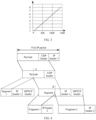
- a mapping curve between a QoS level and a byte length is shown in FIG 3 .
- a horizontal coordinate represents a length
- a vertical coordinate represents a QoS level.
- a length corresponding to any QoS level in the setting needs to be less than a difference 1440 between a length 1500 of the MTU and a maximum value 60 of the IP header length. As shown in Table 1, a maximum length corresponding to the QoS level is 1440.
- the correspondence between a QoS level and a byte length needs to meet the following requirements: The correspondence complies with a protocol principle and cannot violate a protocol rule; and the correspondence between a QoS level and a byte length is a one-to-one correspondence.
- the first proxy device may set a byte length corresponding to a QoS level to a relatively small value. Specifically, a maximum value of the byte length corresponding to the QoS level may be less than or equal to a sum of a minimum value of the MPTCP header length and a minimum value of the IP header length.
- a length of the MPTCP packet is necessarily greater than the sum of the minimum value of the MPTCP header length and the minimum value of the IP header length. Therefore, when the maximum value of the byte length corresponding to the QoS level is less than or equal to the sum of the minimum value of the MPTCP header length and the minimum value of the IP header length, the payload length of the target IP packet is less than the sum of the minimum value of the MPTCP header length and the minimum value of the IP header length, and the length of the MPTCP packet is necessarily greater than or equal to the maximum value of the byte length corresponding to the QoS level. In other words, the length of the MPTCP packet is necessarily greater than or equal to the byte length corresponding to the target QoS level. Therefore, operations of adding padding data to an MPTCP packet can be decreased or reduced, to simplify the data processing process.
- Both the minimum value of the MPTCP header length and the minimum value of the IP header length are 20 bytes. Therefore, the length corresponding to the target QoS level may be less than or equal to 40 bytes.
- the first proxy device may not compare the length of the MPTCP packet with the byte length corresponding to the target QoS level, but directly perform the operation of dividing the first MPTCP packet into at least two MPTCP packet fragments.
- an IP header added by the first proxy device when the first proxy device encapsulates each MPTCP packet into a corresponding second IP packet is the second IP header in step 103.
- the second IP header is an IP header on an outermost side of a second IP packet corresponding to each segment obtained in step 103.
- the first proxy device sends the at least one second IP packet to a second proxy device by using an MPTCP connection with the second proxy device
- the first device may send the at least one second IP packet by using the MPTCP connection between the first proxy device and the second proxy device.
- the MPTCP header in the second IP packet usually includes source port information and destination port information
- the second IP header on the outmost side of the second IP packet usually includes source address information and destination address information
- the second proxy device After receiving the at least one second IP packet that belongs to a same MPTCP packet by using the MPTCP connection with the first proxy device, the second proxy device obtains a payload length of a target IP packet in the at least one second IP packet.
- the second proxy device may identify, based on second IP headers in the second IP packets, second IP packets that belong to a same MPTCP packet.
- a location of a target IP packet in the second IP packets of the same MPTCP packet is preset in the second proxy device. Therefore, the target IP packet in the second IP packets that belong to the same MPTCP packet may be determined, and a payload length of the target IP packet may be obtained. Specifically, the payload length of the target IP packet may be obtained from an IP header of the target IP packet.
- the second proxy device determines the target QoS level of the at least one second IP packet based on the payload length of the target IP packet.
- the first proxy device divides the received UDP packet into the at least two segments. After each segment is encapsulated into an MPTCP packet, the MPTCP packet is encapsulated into at least one second IP packet, and the payload length of the target IP packet in the at least one second IP packet is equal to the byte length corresponding to the target QoS level. In other words, a target QoS level of the same MPTCP packet is indicated by using the payload length of the target IP packet.
- the second proxy device may accurately determine the target QoS level of the same MPTCP packet based on the payload length of the target IP packet, and accurately perform corresponding QoS processing on the at least one second IP packet that belongs to the same MPTCP packet. This avoids a problem that the peer device cannot determine the corresponding QoS processing on the UDP packet because there is no QoS information in an IP header encapsulated on an outermost side of the UDP packet.
- the first proxy device receives the first IP packet in step 101.
- the first IP packet includes a UDP packet and a first IP header.
- an IP header 1 represents the first IP header
- the UDP packet includes two parts: a UDP header and payload.
- the first proxy device divides the UDP packet into at least two segments. As shown in FIG 4 , for example, the UDP packet is divided into two segments by the first proxy device.
- the UDP packet including the UDP header and the payload is divided by a dashed line A, to obtain two segments: a segment 1 and a segment 2.
- a sum of a length of each segment and a length of the IP header 1 is less than or equal to a difference between an MTU and a first length.
- the first length is a sum of a length of an MPTCP header corresponding to each segment and a length of a second IP header corresponding to each segment.
- step 104 is performed.
- the first proxy device encapsulates each segment into an MPTCP packet. As shown in FIG 4 , the IP header 1 and the MPTCP header are encapsulated for each of the segment 1 and the segment 2.
- the first IP header and the MPTCP header are encapsulated.
- a payload length indication field in the IP header 1 is modified to a length of each segment.
- step 105 is performed.
- the first proxy device encapsulates each MPTCP packet into at least one second IP packet. As shown in FIG 4 , for example, an MPTCP packet obtained after the segment 2 is encapsulated is encapsulated into two second IP packets, and a target IP packet is a start IP packet in the two second IP packets.
- the first proxy device divides, by a dashed line B, the MPTCP packet obtained after the segment 2 is encapsulated into two MPTCP packet fragments: a fragment 1 and a fragment 2.
- the fragment 2 is a start MPTCP packet fragment, namely, a target MPTCP packet fragment.
- each of the MPTCP packet fragments is encapsulated into a second IP packet.
- an IP header 2 represents the second IP header, and the second IP packet including the fragment 2 and the corresponding IP header 2 is the target IP packet.
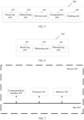
- FIG 5 is a schematic block diagram of an apparatus 200 for determining quality of service according to an embodiment of the present invention. As shown in FIG 5 , the apparatus 200 includes:
- the received UDP packet is divided into at least two segments. After each segment is encapsulated into an MPTCP packet, the MPTCP packet is encapsulated into at least one second IP packet.
- the payload length of the target IP packet in the at least one second IP packet is equal to the byte length corresponding to the target QoS level. In other words, a target QoS level of a same MPTCP packet is indicated by using the payload length of the target IP packet.
- the peer device may accurately determine the target QoS level of the same MPTCP packet based on the payload length of the target IP packet, and accurately perform corresponding QoS processing on the UDP packet. This avoids a problem that the peer device cannot determine the corresponding QoS processing on the UDP packet because there is no QoS information in an IP header encapsulated on an outermost side of the UDP packet.
- the encapsulation unit 204 when encapsulating each of the at least two segments into an MPTCP packet, is specifically configured to:
- the encapsulation unit 204 when encapsulating each of the at least two segments into an MPTCP packet, is specifically configured to:
- the target IP packet is a start IP packet in the at least one second IP packet.
- a sum of a length of each of the at least two segments and a length of the first IP header is less than or equal to a difference between a maximum transmission unit (MTU) and a first length
- the first length is a sum of a length of an MPTCP header corresponding to each segment and a length of an IP header of a second IP packet corresponding to each segment.
- a sum of a length of each of the at least one segment and the length of the first IP header is less than or equal to a preset length
- the preset length is a difference between the MTU and a first preset value
- the first preset value is a sum of a maximum value of an MPTCP header length and a maximum value of an IP header length.
- the determining unit 202 is further configured to determine, based on a correspondence between a QoS level and a byte length, the byte length corresponding to the target QoS level.
- the correspondence between a QoS level and a byte length is preset, and a maximum value of a byte length corresponding to each QoS level in the correspondence is less than or equal to a sum of a minimum value of the MPTCP header length and a minimum value of the IP header length.
- the encapsulation unit when encapsulating each of the at least two segments into an MPTCP packet, is specifically configured to:
- the apparatus 200 for determining quality of service according to this embodiment of the present invention may correspond to an entity for executing the method for determining quality of service according to the foregoing embodiment of the present invention, and the foregoing and other operations and/or functions of the modules in the apparatus 200 for determining quality of service are separately used to implement corresponding procedures of the methods executed by the first proxy device in FIG 2 .
- the foregoing and other operations and/or functions of the modules in the apparatus 200 for determining quality of service are separately used to implement corresponding procedures of the methods executed by the first proxy device in FIG 2 .
- FIG 6 is a schematic block diagram of an apparatus 300 for determining quality of service according to another embodiment of the present invention. As shown in FIG 6 , the apparatus 300 includes:
- the peer device indicates a target QoS level of the same MPTCP packet by using the payload length of the target IP packet. Therefore, after the at least one IP packet that belongs to the same MPTCP packet is received, the target QoS level of the same MPTCP packet may be accurately determined based on the payload length of the target IP packet in the at least one IP packet, and corresponding QoS processing may be accurately performed on a UDP packet. This avoids a problem that the corresponding QoS processing on the UDP packet cannot be determined because there is no QoS information in an IP header encapsulated on an outermost side of the UDP packet.
- the target IP packet is a start IP packet in the at least one IP packet.
- the payload length of the target IP packet is less than or equal to a sum of a minimum value of an MPTCP header length and a minimum value of an IP header length.
- the apparatus 300 for determining quality of service according to this embodiment of the present invention may correspond to an entity for executing the method for determining quality of service according to the foregoing embodiment of the present invention, and the foregoing and other operations and/or functions of the modules in the apparatus 300 for determining quality of service are separately used to implement corresponding procedures of the methods executed by the second proxy device in FIG 2 .
- the foregoing and other operations and/or functions of the modules in the apparatus 300 for determining quality of service are separately used to implement corresponding procedures of the methods executed by the second proxy device in FIG 2 .
- FIG 7 is a schematic block diagram of a device 400 for determining quality of service according to an example.
- the device 400 is connected to a plurality of hard disks.
- the device 400 includes a processor 401, a memory 402, and a communications interface 403.
- the memory 402 is configured to store executable program code.
- the processor 401 runs, by reading the executable program code stored in the memory 402, a program corresponding to the executable program code.
- the communications interface 403 is configured to communicate with an external device.
- the device 400 may further include a bus 404.
- the bus 404 is configured to connect the processor 401, the memory 402, and the communications interface 403, so that the processor 401, the memory 402, and the communications interface 403 communicate with each other by using the bus 404.
- the device 400 according to this example may correspond to an entity for executing the method for determining quality of service according to the foregoing example, and the foregoing operations and/or functions in the device 400 are separately used to implement corresponding procedures of the methods executed by the first proxy device in FIG 2 .
- the foregoing operations and/or functions in the device 400 are separately used to implement corresponding procedures of the methods executed by the first proxy device in FIG 2 .
- details are not described herein again.
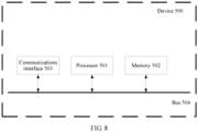
- FIG 8 is a schematic block diagram of a device 500 for determining quality of service according to another example.
- the device 500 is connected to a plurality of hard disks.
- the device 500 includes a processor 501, a memory 502, and a communications interface 503.
- the memory 502 is configured to store executable program code.
- the processor 501 runs, by reading the executable program code stored in the memory 502, a program corresponding to the executable program code.
- the communications interface 503 is configured to communicate with an external device.
- the device 500 may further include a bus 504.
- the bus 504 is configured to connect the processor 501, the memory 502, and the communications interface 503, so that the processor 501, the memory 502, and the communications interface 503 communicate with each other by using the bus 504.
- the device 500 may correspond to an entity for executing the method for determining quality of service according to the foregoing example, and the foregoing operations and/or functions in the device 500 are separately used to implement corresponding procedures of the methods executed by the first proxy device in FIG 2 .
- the foregoing operations and/or functions in the device 500 are separately used to implement corresponding procedures of the methods executed by the first proxy device in FIG 2 .
- details are not described herein again.
- All or some of the foregoing embodiments may be implemented by using software, hardware, firmware, or any combination thereof.
- the embodiments may be implemented fully or partially in a form of a computer program product.
- the computer program product includes one or more computer instructions.
- the computer may be a general-purpose computer, a special-purpose computer, a computer network, or another programmable apparatus.
- the computer instructions may be stored in a computer-readable storage medium or may be transmitted from one computer-readable storage medium to another computer-readable storage medium.
- the computer instructions may be transmitted from one website, computer, server, or data center to another website, computer, server, or data center in a wired (for example, a coaxial cable, an optical fiber, or a digital subscriber line (DSL)) or wireless (for example, infrared, radio, or microwave) manner.
- the computer-readable storage medium may be any usable medium accessible by a computer, or a data storage device, such as a server or a data center, integrating one or more usable media.
- the usable medium may be a magnetic medium (for example, a floppy disk, a hard disk, or a magnetic tape), an optical medium (for example, a DVD), a semiconductor medium (for example, a solid state disk (Solid State Disk, SSD)), or the like.
- a magnetic medium for example, a floppy disk, a hard disk, or a magnetic tape
- an optical medium for example, a DVD
- a semiconductor medium for example, a solid state disk (Solid State Disk, SSD)
Landscapes
- Engineering & Computer Science (AREA)
- Computer Networks & Wireless Communication (AREA)
- Signal Processing (AREA)
- Computer Security & Cryptography (AREA)
- Data Exchanges In Wide-Area Networks (AREA)
Description
- The present invention relates to the field of communications technologies, and in particular, to a method and a system for determining quality of service, and a storage medium.
- A multipath transmission control protocol (Multipath Transmission Control Protocol, MPTCP) is a transport layer protocol in which a plurality of paths are used for concurrent transmission, so that an end-to-end throughput can be increased and network utilization can be improved. Services on a network mainly include a transmission control protocol (Transmission Control Protocol, TCP) service and a user datagram protocol (User Datagram Protocol, UDP) service. The TCP service and the UDP service use different protocols. Therefore, a TCP service stream and a UDP service stream are transmitted in different manners in the MPTCP.
- The UDP service stream is usually transmitted in the MPTCP by using a tunneling technology. To be specific, after receiving a UDP packet, a device such as a router encapsulates an MPTCP header and a new IP header outside an Internet protocol (Internet Protocol, IP) packet in which the UDP packet is encapsulated, to obtain a new packet, and then sends the new packet to a peer end by using an MPTCP connection. The original IP packet (for example, an IP header of the original IP packet or a UDP header of the UDP packet) in which the UDP packet is encapsulated includes quality of service (Quality of Service, QoS) information. The QoS information may be used to determine a QoS level of the UDP packet.
Boucadair et al, "An MPTCP Option for Network-Assisted MPTCP Deployments: Plain Transport Mode", IETF; Standardworkingdraft, Switzerland, 2016-07-04, discloses an MCTCP option that is used to avoid the encapsulation of packets and out-of-band signaling between the CPE and the MPTCP concentrator.
US2009/245224 A1 discloses a method and apparatus that provides quality of service in wireless or sensor networks is disclosed.
US2009/285108 A1 discloses a method for providing Quality of Service (QoS) for a Multilink Protocol (MP) subscriber at the subscriber level is described.
EP3119057 A1 discloses an adapted conversion device implementation for transparent packet-based multipath bundling protocol to realize a hybrid access efficiently.
Boucadair, M et al, "Network-Assisted MPTCP: Use Cases, Deployment Scenarios and Operational Considerations", IETF; standardworkingdraft, ISOC, Switzerland, 2016-12-07, discloses network-assisted MPTCP use cases, deployment scenarios, and operational considerations.
When the UDP service stream is transmitted in the MPTCP, the new TCP header and the new IP header are encapsulated outside the original UDP packet, but there is no QoS information in the IP header that is encapsulated on an outermost side of the UDP packet. Therefore, after receiving the UDP packet, a peer device receiving the UDP packet cannot obtain the QoS information, and consequently cannot determine the QoS level of the UDP packet. As a result, the peer device cannot perform corresponding QoS processing on the UDP packet accurately. - This application provides a method and a system for determining quality of service, and a storage medium, to resolve a problem that corresponding QoS processing cannot be accurately performed on a UDP packet. The present invention is disclosed according to the independent claims. The dependent claims recite advantageous embodiments of the invention.
- According to a first aspect, this application provides
- a method for determining quality of service in a system comprising a first device and
- a second device comprising:
- receiving, by the first device, a first Internet protocol, IP, packet, wherein the first IP packet comprises a user datagram protocol, UDP, packet and a first IP header;
- determining, by the first device, based on information in the first IP packet, a target quality of service, QoS, level to which the UDP packet belongs;
- dividing, by the first device, the UDP packet into at least two segments;
- encapsulating, by the first device, each of the at least two segments into a multipath transmission control protocol, MPTCP, packet;
- encapsulating, by the first device, each MPTCP packet into at least one second IP packet, wherein a payload length of a target IP packet in the at least one second IP packet is equal to a byte length corresponding to the target QoS level; and
- for each segment of the at least two segments sending, by the first device the at least one second IP packet to the second device by using an MPTCP connection with the second device:
- receiving, by the second device, using a multipath transmission control protocol, MPTCP, connection with the first device, at least one Internet protocol, IP, packet that belongs to a same MPTCP packet and that is sent by the first device;
- obtaining, by the second device, a payload length of a target IP packet in the at least one IP packet; and
- determining, by the second device, based on the payload length of the target IP packet, a target quality of service, QoS, level of the at least one IP packet;
- wherein the target IP packet is a packet at a preset location in the at least one second IP packet.
- In this application, the received UDP packet is divided into at least two segments. After each segment is encapsulated into an MPTCP packet, the MPTCP packet is encapsulated into at least one second IP packet. In addition, the payload length of the target IP packet in the at least one second IP packet is equal to the byte length corresponding to the target QoS level. In other words, a target QoS level of a same MPTCP packet is indicated by using the payload length of the target IP packet. Therefore, in this application, after the second IP packet obtained through encapsulation is sent to the second device by using the MPTCP connection, the second device may accurately determine the target QoS level of the same MPTCP packet based on the payload length of the target IP packet, and accurately perform corresponding QoS processing on the UDP packet. This avoids a problem that the second device cannot determine the corresponding QoS processing on the UDP packet because there is no QoS information in an IP header encapsulated on an outermost side of the UDP packet.
Thesecond device indicates a target QoS level of the same MPTCP packet by using the payload length of the target IP packet. Therefore, after the at least one IP packet that belongs to the same MPTCP packet is received, the target QoS level of the same MPTCP packet may be accurately determined based on the payload length of the target IP packet in the at least one IP packet, and corresponding QoS processing may be accurately performed on a UDP packet. This avoids a problem that the corresponding QoS processing on the UDP packet cannot be determined because there is no QoS information in an IP header encapsulated on an outermost side of the UDP packet. - With reference to the first aspect, in a first implementation of the first aspect, the encapsulating, by the first device, each MPTCP packet into at least one second IP packet includes:
- for a first MPTCP packet in all the MPTCP packets, dividing the first MPTCP packet into at least two MPTCP packet fragments, where a length of a target MPTCP packet fragment in the at least two MPTCP packet fragments is equal to the byte length corresponding to the target QoS level, and a length of the first MPTCP packet is greater than the byte length corresponding to the target QoS level; and
- encapsulating, by the first device, the at least two MPTCP packet fragments into corresponding second IP packets, where a second IP packet corresponding to the target MPTCP packet fragment is the target IP packet.
- With reference to the first aspect or any implementation above, in a second implementation of the first aspect, the encapsulating, by the first device, each MPTCP packet into at least one second IP packet includes:
- for a second MPTCP packet in all the MPTCP packets, adding padding data to the second MPTCP packet, so that a length of the second MPTCP packet to which the padding data is added is equal to the byte length corresponding to the target QoS level, where a length of the second MPTCP packet is less than the byte length corresponding to the target QoS level; and
- encapsulating, by the first device, the second MPTCP packet to which the padding data is added into a corresponding second IP packet, where the second IP packet corresponding to the second MPTCP packet to which the padding data is added is the target IP packet.
- With reference to the first aspect or any implementation above, in a third implementation of the first aspect, the target IP packet is a start IP packet in the at least one second IP packet.
- With reference to the first aspect or any implementation above, in a fourth implementation of the first aspect, a sum of a length of each of the at least two segments and a length of the first IP header is less than or equal to a difference between a maximum transmission unit (MTU) and a first length, and the first length is a sum of a length of an MPTCP header corresponding to each segment and a length of an IP header of a second IP packet corresponding to each segment.
- With reference to the first aspect or any implementation above, in a fifth implementation of the first aspect, a sum of a length of each of the at least one segment and the length of the first IP header is less than or equal to a preset length, the preset length is a difference between the MTU and a first preset value, and the first preset value is a sum of a maximum value of an MPTCP header length and a maximum value of an IP header length.
- With reference to the first aspect or any implementation above, in a sixth implementation of the first aspect, before the encapsulating, by the first device, each MPTCP packet into at least one second IP packet, the method further includes:
determining, by the first device, based on a correspondence between a QoS level and a byte length, the byte length corresponding to the target QoS level. - With reference to the first aspect or any implementation above, in a seventh implementation of the first aspect, the correspondence between a QoS level and a byte length is preset, and a maximum value of a byte length corresponding to each QoS level in the correspondence is less than or equal to a sum of a minimum value of the MPTCP header length and a minimum value of the IP header length.
- With reference to the first aspect or any implementation above, in an eighth implementation of the first aspect, the encapsulating, by the first device, each of the at least two segments into a multipath transmission control protocol (MPTCP) packet includes:
- encapsulating the first IP header for each segment, where a payload length indication field in the first IP header is modified to a length of the corresponding segment; and
- encapsulating each segment after the first IP header is encapsulated into an MPTCP packet.
- With reference to the first aspect or any implementation above, in a further implementation of the first aspect, the payload length of the target IP packet is less than or equal to a sum of a minimum value of an MPTCP header length and a minimum value of an IP header length.
- According to a second aspect, this application provides a system for determining quality of service, the system comprising a first device and a second device, the first device comprising:
- a receiving unit, configured to receive a first Internet protocol (IP) packet, where the first IP packet includes a user datagram protocol (UDP) packet and a first IP header;
- a determining unit, configured to determine, based on information in the first IP packet, a quality of service target QoS level to which the UDP packet belongs;
- a division unit, configured to divide the UDP packet into at least two segments;
- an encapsulation unit, configured to encapsulate each of the at least two segments into a multipath transmission control protocol (MPTCP) packet, where
- the encapsulation unit is further configured to encapsulate each MPTCP packet into at least one second IP packet, and a payload length of a target IP packet in the at least one second IP packet is equal to a byte length corresponding to the target QoS level; and
- a sending unit, configured to send for each of the at least two segments the at least one second IP packet to the second device by using an MPTCP connection with the peer device; and the second device comprising:
- a receiving unit, configured to receive, by using a multipath transmission control protocol, MPTCP, connection with a peer device, at least one Internet protocol, IP, packet that belongs to a same MPTCP packet and that is sent by the first device;
- an obtaining unit, configured to obtain a payload length of a target IP packet in the at least one IP packet; and
- a determining unit, configured to determine, based on the payload length of the target IP packet, a target quality of service, QoS, level of the at least one IP packet;
- wherein the target IP packet is a packet at a preset location in the at least one second IP packet.
- With reference to the second aspect, in a first implementation of the second aspect, when encapsulating each of the at least two segments into an MPTCP packet, the encapsulation unit is specifically configured to:
- for a first MPTCP packet in all the MPTCP packets, divide the first MPTCP packet into at least two MPTCP packet fragments, where a length of a target MPTCP packet fragment in the at least two MPTCP packet fragments is equal to the byte length corresponding to the target QoS level, and a length of the first MPTCP packet is greater than the byte length corresponding to the target QoS level; and
- encapsulate the at least two MPTCP packet fragments into corresponding second IP packets, where a second IP packet corresponding to the target MPTCP packet fragment is the target IP packet.
- To describe the technical solutions in the embodiments of the present invention more clearly, the following briefly describes the accompanying drawings required for describing the embodiments apparently.
-
FIG 1 is a schematic diagram of a network architecture according to an embodiment of the present invention; -
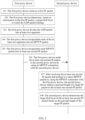
FIG 2 is a schematic flowchart of a method for determining quality of service according to an embodiment of the present invention; -
FIG 3 is a schematic diagram of a mapping curve between a fragment length and a QoS value according to an embodiment of the present invention; -
FIG 4 is a schematic diagram of a process of processing a first IP packet according to an embodiment of the present invention; -
FIG 5 is a schematic block diagram of an apparatus for determining quality of service according to an embodiment of the present invention; -
FIG 6 is a schematic block diagram of an apparatus for determining quality of service according to another embodiment of the present invention; -
FIG 7 is a schematic block diagram of a device for determining quality of service according to an example not being part of the present invention but useful for understanding the present invention; and -
FIG 8 is a schematic block diagram of a device for determining quality of service according to another example not being part of the present invention but useful for understanding the present invention. - To make the objectives, technical solutions, and advantages of the embodiments of the present invention clearer, the following clearly and completely describes the technical solutions of the embodiments of the present invention with reference to the accompanying drawings in the embodiments of the present invention. In a case that no conflict occurs, the embodiments in the application and the features in the embodiments may be mutually combined.
- The embodiments of the present invention may be applied to a scenario of determining quality of service.
FIG 1 is a schematic diagram of a network architecture according to an embodiment of the present invention. As shown inFIG 1 , data transmission based on an MPTCP network is implemented between a client and a server by using a TCP proxy. InFIG 1 , the client communicates with a first proxy device by using the UDP protocol. A multipath network is between the first proxy device and a second proxy device. The multipath network may include a digital subscriber line (Digital Subscriber Line, DSL), LTE (Long Term Evolution, long term evolution), a wireless fidelity (Wireless Fidelity, Wi-Fi) connection, and the like. To transmit a UDP packet in the multipath network, an MPTCP connection is established between the first proxy device and the second proxy device. The second proxy device communicates with the server by using the UDP protocol. The first proxy device and the second proxy device may serve as a peer device of each other. - Specifically, the architecture shown in
FIG 1 may be applied to a bonding access (Bonding Access, BA) scenario or a software-defined wide area network (Software-Defined Wide Area Network, SD-WAN) scenario. In the BA scenario, the client may be a client using the UDP protocol to host an application, for example, a computer or a mobile phone of a home user. The client may access an application on an external UDP server, for example, a video live broadcast. The first proxy device may be a network access device installed in the user's home by an operator. For example, the first proxy device may be a home gateway (Home Gateway, HG). The first proxy device may include a plurality of interfaces, such as an asymmetric digital subscriber line (Asymmetric Digital Subscriber Line, ADSL) interface, a Wi-Fi interface, and an LTE interface. These interfaces may be used by the first proxy device as different output interfaces for MPTCP multipath transmission, to implement hybrid access to data transmitted on a plurality of paths. The second proxy device may be a hybrid access aggregation point (Hybrid Access Aggregation Point, HAAP), and is configured to receive hybrid access requests from different HGs. The server may be a server that uses the UDP protocol to host an application. In the SD-WAN scenario, the client may be a client that is in an enterprise branch (Branch) and that uses the UDP protocol to host an application, and may be configured to access an application on a server that is in an enterprise headquarter (Head-quarter, HQ) and that uses the UDP protocol to host an application. The first proxy device and the second proxy device may be access routing devices, and the access routing devices may include a plurality of interfaces, such as an ADSL interface, a Wi-Fi interface, and an LTE interface. These interfaces may be used as different output interfaces for MPTCP multipath transmission, to implement hybrid access to data transmitted on a plurality of paths. The server may be a data center server that is in an enterprise headquarter and that uses the UDP protocol to host an application. - An embodiment of the present invention provides a method for determining quality of service. The method may be applied to the network architecture shown in
FIG 1 . As shown inFIG 2 , the method includes the following steps. - 101. A first proxy device receives a first IP packet.
- When a client needs to communicate with a server, the client sends the first IP packet to the first proxy device by using a UDP protocol between the client and the first proxy device. The first IP packet includes a UDP packet and a first IP header. In other words, the UDP packet is payload of the first IP packet. The UDP packet includes payload and a UDP header. The first IP header includes QoS information and a payload length indication field. In this case, the payload length indication field in the first IP header indicates a length of the UDP packet. The first proxy device receives the first IP packet, and may separately store the UDP packet and the first IP header of the first IP packet.
- 102. The first proxy device determines, based on information in the first IP packet, a target QoS level to which the UDP packet belongs.
- The first proxy device may determine, based on the QoS information included in the first IP header and/or a packet header (namely, the UDP header) of the UDP packet, the target QoS level to which the UDP packet belongs. The QoS information may specifically include one or any combination of information included in the first IP packet, such as a source IP address, a destination IP address, or a differentiated services code point (Differentiated Services Code Point, DSCP).
- Specifically, a QoS level classification rule may be preset in the first proxy device. For example, the QoS level classification rule may be a correspondence between a QoS level and a source IP address and/or a destination IP address. After the first IP packet is received, the target QoS level to which the UDP packet belongs may be determined based on information (for example, the source IP address and the destination IP address) included in the first IP header and the preset QoS level classification rule. The QoS level classification rule may include a plurality of QoS levels. Different QoS levels correspond to different processing manners. For example, transmission queues of different priorities are used for transmission. In addition, a QoS value corresponding to each QoS level may be further set in the first proxy device, and the QoS level may be indicated by using the QoS value. For example, if there are eight QoS levels, QoS values corresponding to the QoS levels may be set to
numbers 1 to 8 in sequence. - 103. The first proxy device divides the UDP packet into at least two segments.
- The first proxy device transmits data by using an MPTCP connection between the first proxy device and a second proxy device. Therefore, when sending the first IP packet to the second proxy device, the first proxy device needs to sequentially encapsulate an MPTCP header and a new IP header (referred to as a second IP header below) outside the first IP packet, so that transmission may be performed by using the MPTCP connection between the first proxy device and the second proxy device.
- When a packet is transmitted between devices, a maximum transmission unit (Maximum Transmission Unit, MTU) is set, to indicate a maximum length of the packet transmitted between the devices. Generally, a length allowed by the MTU is used in transmission between the devices. Therefore, a length of the first IP packet may usually reach the MTU. However, after the MPTCP header and the second IP header are encapsulated outside the first IP packet, a length is much greater than the MTU. In this case, the first proxy device cannot transmit the first IP packet outside which the MPTCP header and the second IP header are encapsulated. Therefore, in this embodiment of the present invention, the first proxy device divides the UDP packet in the first IP packet into at least two segments, and then encapsulates the first IP header, the MPTCP header, and the second IP header outside each of the at least two segments for transmission. In this way, a segment obtained after encapsulation can be shorter than or as long as the MTU, and the first proxy device can transmit the packet.
- To ensure that a length of each of the at least two segments after the first IP header, the MPTCP header, and the second IP header are encapsulated is not greater than the MTU, when the segments are divided, it needs to be ensured that a sum of a length of each segment and a length of the first IP header is less than or equal to a difference between the MTU and a first length. The first length is a sum of a length of the MPTCP header corresponding to each segment and a length of the second IP header corresponding to each segment.
- When the length of each segment after the first IP header, the MPTCP header, and the second IP header are encapsulated is less than or equal to the MTU, the byte length allowed by the MTU can be met. In other words, a sum of the length of each segment, the length of the first IP header, the length of the MPTCP header, and the length of the second IP header is less than or equal to the MTU. Therefore, when the UDP packet is divided into segments, a sum of a length of each segment and the length of the first IP header may be made less than or equal to the difference between the MTU and the first length. The first length is the sum of the length of the MPTCP header corresponding to each segment and the length of the second IP header corresponding to each segment.
- The first proxy device may determine the length of the first IP header by using the first IP packet. The length of the MPTCP header and the length of the second IP header may be calculated with reference to a function of the first IP packet. Therefore, when dividing the UDP packet into segments, the first proxy device may determine a maximum value of a length of each segment based on the MTU, the length of the first IP header, the length of the MPTCP header, and the length of the second IP header.
- To simplify a data processing process of the first proxy device, in this embodiment of the present invention, a specific setting may be as follows: A sum of a length of each of at least one segment and the length of the first IP header is less than or equal to a preset length, a preset length is a difference between the MTU and a first preset value, and the first preset value is a sum of a maximum value of an MPTCP header length and a maximum value of an IP header length.
- The length of the MPTCP header corresponding to each segment is necessarily less than or equal to the maximum value of the MPTCP header length, and the length of the second IP header corresponding to each segment is necessarily less than or equal to the maximum value of the IP header length. Therefore, the first preset value is necessarily greater than or equal to the first length. To be specific, the difference between the MTU and the first preset value is necessarily less than or equal to the difference between the MTU and the first length. Therefore, in this embodiment of the present invention, the first proxy device may determine a sum of the length of each segment and the length of the first IP packet based on the MTU, the maximum value of the MPTCP header length, and the maximum value of the IP header length, and the determined sum of the length of each segment and the length of the first IP packet is necessarily less than or equal to the difference between the MTU and the first length. Therefore, it can be ensured that the length of each segment after the first IP header, the MPTCP header, and the second IP header are encapsulated is not greater than the MTU.
- Usually, both the maximum value of the MPTCP header length and the maximum value of the IP header length are 60 bytes. Therefore, in this embodiment of the present invention, the first preset value may be set to 120 bytes.
- It should be noted that a manner in which the first proxy device divides the UDP packet into segments is not limited, provided that the sum of the length of each segment and the length of the first IP header is less than or equal to the difference between the MTU and the first length. The first length is the sum of the length of the MPTCP header corresponding to each segment and the length of the second IP header corresponding to each segment. The first proxy device divides the UDP packet in the first IP packet into at least two segments, and a target QoS level of a UDP packet included in each of the at least two segments is the same as the target QoS level of the UDP packet in the first IP packet.
- 104. The first proxy device encapsulates each of the at least two segments into an MPTCP packet.
- After dividing the UDP packet into the at least two segments in
step 103, the first proxy device encapsulates each segment into an MPTCP packet. - When encapsulating each of the at least two segments, the first proxy device needs to first encapsulate the first IP header, so that each segment can be transmitted to a destination address in the first IP header. In this case, each segment is payload corresponding to the first IP header. Therefore, the payload length indication field in the first IP header is modified to a length of each segment. To be specific, when the first IP header is encapsulated for each segment, the payload length indication field in the first IP header is modified to a length of the segment, to ensure accuracy of information in the first IP header.
- For each segment, the first proxy device encapsulates a first IP header having a payload length indication field modified, and then encapsulates the MPTCP header, that is, encapsulates each of the at least two segments into the MPTCP packet.
- 105. The first proxy device encapsulates each MPTCP packet into at least one second IP packet.
- A payload length of a target IP packet in the at least one second IP packet is equal to a byte length corresponding to the target QoS level. In this embodiment of the present invention, when encapsulating each MPTCP packet into the at least one second IP packet, the first proxy device reflects a target QoS level of each MPTCP packet by using the payload length of the target IP packet in the at least one second IP packet. Usually, a payload length of an IP packet is carried in an IP header. Therefore, a second IP header of the target IP packet may carry the payload length.
- The target IP packet is a packet at a preset location in the at least one second IP packet, for example, a start IP packet in the at least one second IP packet or a last IP packet in the at least one second IP packet.
- Lengths of MPTCP packets are different, and sometimes a length of an MPTCP packet cannot reach the byte length corresponding to the target QoS level. In this case, padding data needs to be added to the MPTCP packet.
- Specifically, when encapsulating each MPTCP packet, the first proxy device may further compare a length of the MPTCP packet with the byte length corresponding to the target QoS level.
- For a first MPTCP packet that is in the MPTCP packets and whose length is greater than the byte length corresponding to the target QoS level, the first MPTCP packet may be divided into at least two MPTCP packet fragments, and a length of a target MPTCP packet fragment in the at least two MPTCP packet fragments is equal to the byte length corresponding to the target QoS level. The at least two MPTCP packet fragments are encapsulated into corresponding second IP packets, and a second IP packet corresponding to the target MPTCP packet fragment is the target IP packet. For a second MPTCP packet that is in the MPTCP packets and whose length is less than the byte length corresponding to the target QoS level, padding data may be added to the second MPTCP packet, so that a length of the second MPTCP packet to which the padding data is added is equal to the byte length corresponding to the target QoS level. The second MPTCP packet to which the padding data is added is encapsulated into a corresponding second IP packet, and the second IP packet corresponding to the second MPTCP packet to which the padding data is added is the target IP packet. For a third MPTCP packet that is in the MPTCP packets whose length is equal to the byte length corresponding to the target QoS level, the third MPTCP packet may be directly encapsulated into a corresponding second IP packet, namely, the target IP packet.
- When the length of the MPTCP packet is greater than the byte length corresponding to the target QoS level, because the length of the target MPTCP packet fragment needs to be equal to the byte length corresponding to the target QoS level, the first proxy device may divide the MPTCP packet into at least two MPTCP packet fragments. During division, the length of the target MPTCP packet fragment is equal to the byte length corresponding to the target QoS level, and a length and a quantity of remaining fragments may be determined based on a requirement in an actual scenario or the length of the MPTCP packet. After dividing the MPTCP packet into the MPTCP packet fragments, the first proxy device encapsulates each of the MPTCP packet fragments into a corresponding second IP packet. The target IP packet is a second IP packet obtained after the target MPTCP packet fragment is encapsulated, and each of the MPTCP packet fragments is payload of the corresponding second IP packet.
- When the length of the MPTCP packet is less than the byte length corresponding to the target QoS level, the length of the MPTCP packet cannot reach the byte length corresponding to the target QoS level. Therefore, padding data needs to be added to the MPTCP packet, so that a length of the MPTCP packet to which the padding data is added is equal to the length corresponding to the target QoS level. In this case, the MPTCP packet to which the padding data is added is payload of the target IP packet. Then, the first proxy device encapsulates the MPTCP packet to which the padding data is added into a corresponding second IP packet, namely, the target IP packet.
- When the length of the MPTCP packet is equal to the length corresponding to the target QoS level, the first proxy device may directly encapsulate the MPTCP packet into a corresponding second IP packet, namely, the target IP packet.
- It should be noted that, when the padding data is added to the MPTCP packet, the padding data may be added behind payload corresponding to the first IP header. Correspondingly, before the padding data is added, the payload length indication field in the first IP header may indicate a length of a corresponding segment; when the padding data is added, the payload length indication field in the first IP header may indicate a sum of the length of the corresponding segment and a length of the added padding data, or may indicate the length of the corresponding segment. The padding data may be a number, and specifically may be 0.
- In this embodiment of the present invention, the first proxy device may preset a correspondence between a QoS level and a byte length. Therefore, before
step 105 is performed, the first proxy device may determine, based on the correspondence between a QoS level and a byte length, the byte length corresponding to the target QoS level. In addition, if the first proxy device sets the QoS value corresponding to the QoS level, a correspondence between the QoS value and the byte length may be further set. - In this embodiment of the present invention, the correspondence between a QoS level and a byte length may be set by using a preset function or a correspondence table. A specific correspondence may be set based on a specific service stream. For example, a correspondence table shown in Table 1 may be established. In this case, a mapping curve between a QoS level and a byte length is shown in
FIG 3 . InFIG 3 , a horizontal coordinate represents a length, and a vertical coordinate represents a QoS level.Table 1 QoS level 1 2 3 4 5 6 7 8 Byte length 40 240 440 640 840 1040 1240 1440 - Because a payload length of a second IP packet is used to indicate a corresponding QoS level, a length corresponding to any QoS level in the setting needs to be less than a difference 1440 between a
length 1500 of the MTU and a maximum value 60 of the IP header length. As shown in Table 1, a maximum length corresponding to the QoS level is 1440. - It should be noted that the correspondence between a QoS level and a byte length needs to meet the following requirements: The correspondence complies with a protocol principle and cannot violate a protocol rule; and the correspondence between a QoS level and a byte length is a one-to-one correspondence.
- To reduce operations of adding padding data to an MPTCP packet, and make a length of each MPTCP packet greater than the byte length corresponding to the target QoS level, the first proxy device may set a byte length corresponding to a QoS level to a relatively small value. Specifically, a maximum value of the byte length corresponding to the QoS level may be less than or equal to a sum of a minimum value of the MPTCP header length and a minimum value of the IP header length.
- Because the MPTCP packet is obtained after the first IP header and the MPTCP header are encapsulated for each segment, a length of the MPTCP packet is necessarily greater than the sum of the minimum value of the MPTCP header length and the minimum value of the IP header length. Therefore, when the maximum value of the byte length corresponding to the QoS level is less than or equal to the sum of the minimum value of the MPTCP header length and the minimum value of the IP header length, the payload length of the target IP packet is less than the sum of the minimum value of the MPTCP header length and the minimum value of the IP header length, and the length of the MPTCP packet is necessarily greater than or equal to the maximum value of the byte length corresponding to the QoS level. In other words, the length of the MPTCP packet is necessarily greater than or equal to the byte length corresponding to the target QoS level. Therefore, operations of adding padding data to an MPTCP packet can be decreased or reduced, to simplify the data processing process.
- Both the minimum value of the MPTCP header length and the minimum value of the IP header length are 20 bytes. Therefore, the length corresponding to the target QoS level may be less than or equal to 40 bytes.
- It should be noted that in this embodiment of the present invention, by setting the byte length corresponding to the QoS level, it is ensured that the length of the MPTCP packet is necessarily greater than or equal to the byte length corresponding to the target QoS level. Therefore, in this step, the first proxy device may not compare the length of the MPTCP packet with the byte length corresponding to the target QoS level, but directly perform the operation of dividing the first MPTCP packet into at least two MPTCP packet fragments.
- It should be noted that, in this step, an IP header added by the first proxy device when the first proxy device encapsulates each MPTCP packet into a corresponding second IP packet is the second IP header in
step 103. In other words, the second IP header is an IP header on an outermost side of a second IP packet corresponding to each segment obtained instep 103. - 106. The first proxy device sends the at least one second IP packet to a second proxy device by using an MPTCP connection with the second proxy device
- After encapsulating each MPTCP packet into the at least one second IP packet, the first device may send the at least one second IP packet by using the MPTCP connection between the first proxy device and the second proxy device.
- In this embodiment of the present invention, the MPTCP header in the second IP packet usually includes source port information and destination port information, and the second IP header on the outmost side of the second IP packet usually includes source address information and destination address information.
- 107. After receiving the at least one second IP packet that belongs to a same MPTCP packet by using the MPTCP connection with the first proxy device, the second proxy device obtains a payload length of a target IP packet in the at least one second IP packet.
- After receiving second IP packets by using the MPTCP connection with the first proxy device, the second proxy device may identify, based on second IP headers in the second IP packets, second IP packets that belong to a same MPTCP packet. A location of a target IP packet in the second IP packets of the same MPTCP packet is preset in the second proxy device. Therefore, the target IP packet in the second IP packets that belong to the same MPTCP packet may be determined, and a payload length of the target IP packet may be obtained. Specifically, the payload length of the target IP packet may be obtained from an IP header of the target IP packet.
- 108. The second proxy device determines the target QoS level of the at least one second IP packet based on the payload length of the target IP packet.
- In this embodiment of the present invention, the first proxy device divides the received UDP packet into the at least two segments. After each segment is encapsulated into an MPTCP packet, the MPTCP packet is encapsulated into at least one second IP packet, and the payload length of the target IP packet in the at least one second IP packet is equal to the byte length corresponding to the target QoS level. In other words, a target QoS level of the same MPTCP packet is indicated by using the payload length of the target IP packet. Therefore, in this embodiment of the present invention, after the first proxy device sends the at least one second IP packet obtained through encapsulation to the second proxy device by using the MPTCP connection, the second proxy device may accurately determine the target QoS level of the same MPTCP packet based on the payload length of the target IP packet, and accurately perform corresponding QoS processing on the at least one second IP packet that belongs to the same MPTCP packet. This avoids a problem that the peer device cannot determine the corresponding QoS processing on the UDP packet because there is no QoS information in an IP header encapsulated on an outermost side of the UDP packet.
- In this embodiment of the present invention, a process of processing the first IP packet by the first proxy device in
step 103 to step 105 is described by using a schematic diagram shown inFIG 4 as an example. The first proxy device receives the first IP packet instep 101. The first IP packet includes a UDP packet and a first IP header. InFIG 4 , anIP header 1 represents the first IP header, and the UDP packet includes two parts: a UDP header and payload. Instep 103, the first proxy device divides the UDP packet into at least two segments. As shown inFIG 4 , for example, the UDP packet is divided into two segments by the first proxy device. The UDP packet including the UDP header and the payload is divided by a dashed line A, to obtain two segments: asegment 1 and asegment 2. A sum of a length of each segment and a length of theIP header 1 is less than or equal to a difference between an MTU and a first length. The first length is a sum of a length of an MPTCP header corresponding to each segment and a length of a second IP header corresponding to each segment. Then, step 104 is performed. To be specific, the first proxy device encapsulates each segment into an MPTCP packet. As shown inFIG 4 , theIP header 1 and the MPTCP header are encapsulated for each of thesegment 1 and thesegment 2. In other words, the first IP header and the MPTCP header are encapsulated. When theIP header 1 is encapsulated, a payload length indication field in theIP header 1 is modified to a length of each segment. Then, step 105 is performed. To be specific, the first proxy device encapsulates each MPTCP packet into at least one second IP packet. As shown inFIG 4 , for example, an MPTCP packet obtained after thesegment 2 is encapsulated is encapsulated into two second IP packets, and a target IP packet is a start IP packet in the two second IP packets. The first proxy device divides, by a dashed line B, the MPTCP packet obtained after thesegment 2 is encapsulated into two MPTCP packet fragments: afragment 1 and afragment 2. Thefragment 2 is a start MPTCP packet fragment, namely, a target MPTCP packet fragment. Then, each of the MPTCP packet fragments is encapsulated into a second IP packet. InFIG 4 , anIP header 2 represents the second IP header, and the second IP packet including thefragment 2 and thecorresponding IP header 2 is the target IP packet. -
FIG 5 is a schematic block diagram of anapparatus 200 for determining quality of service according to an embodiment of the present invention. As shown inFIG 5 , theapparatus 200 includes: - a receiving
unit 201, configured to receive a first Internet protocol (IP) packet, where the first IP packet includes a user datagram protocol (UDP) packet and a first IP header; - a determining
unit 202, configured to determine, based on information in the first IP packet, a target QoS level to which the UDP packet belongs; - a
division unit 203, configured to divide the UDP packet into at least two segments; - an
encapsulation unit 204, configured to encapsulate each of the at least two segments into a multipath transmission control protocol (MPTCP) packet, where - the
encapsulation unit 204 is further configured to encapsulate each MPTCP packet into at least one second IP packet, and a payload length of a target IP packet in the at least one second IP packet is equal to a byte length corresponding to the target QoS level; and - a sending
unit 205, configured to send the at least one second IP packet to a peer device by using an MPTCP connection with the peer device, so that the peer device determines the target QoS level based on the payload length of the target IP packet. - In this embodiment of the present invention, the received UDP packet is divided into at least two segments. After each segment is encapsulated into an MPTCP packet, the MPTCP packet is encapsulated into at least one second IP packet. In addition, the payload length of the target IP packet in the at least one second IP packet is equal to the byte length corresponding to the target QoS level. In other words, a target QoS level of a same MPTCP packet is indicated by using the payload length of the target IP packet. Therefore, in this embodiment of the present invention, after the second IP packet obtained through encapsulation is sent to the peer device by using the MPTCP connection, the peer device may accurately determine the target QoS level of the same MPTCP packet based on the payload length of the target IP packet, and accurately perform corresponding QoS processing on the UDP packet. This avoids a problem that the peer device cannot determine the corresponding QoS processing on the UDP packet because there is no QoS information in an IP header encapsulated on an outermost side of the UDP packet.
- It may be understood that when encapsulating each of the at least two segments into an MPTCP packet, the
encapsulation unit 204 is specifically configured to: - for a first MPTCP packet in all the MPTCP packets, divide the first MPTCP packet into at least two MPTCP packet fragments, where a length of a target MPTCP packet fragment in the at least two MPTCP packet fragments is equal to the byte length corresponding to the target QoS level, and a length of the first MPTCP packet is greater than the byte length corresponding to the target QoS level; and
- encapsulate the at least two MPTCP packet fragments into corresponding second IP packets, where a second IP packet corresponding to the target MPTCP packet fragment is the target IP packet.
- It may be understood that when encapsulating each of the at least two segments into an MPTCP packet, the
encapsulation unit 204 is specifically configured to: - for a second MPTCP packet in all the MPTCP packets, add padding data to the second MPTCP packet, so that a length of the second MPTCP packet to which the padding data is added is equal to the byte length corresponding to the target QoS level, where a length of the second MPTCP packet is less than the byte length corresponding to the target QoS level; and
- encapsulate the second MPTCP packet to which the padding data is added into a corresponding second IP packet, where the second IP packet corresponding to the second MPTCP packet to which the padding data is added is the target IP packet.
- It may be understood that the target IP packet is a start IP packet in the at least one second IP packet.
- It may be understood that a sum of a length of each of the at least two segments and a length of the first IP header is less than or equal to a difference between a maximum transmission unit (MTU) and a first length, and the first length is a sum of a length of an MPTCP header corresponding to each segment and a length of an IP header of a second IP packet corresponding to each segment.
- It may be understood that a sum of a length of each of the at least one segment and the length of the first IP header is less than or equal to a preset length, the preset length is a difference between the MTU and a first preset value, and the first preset value is a sum of a maximum value of an MPTCP header length and a maximum value of an IP header length.
- It may be understood that the determining
unit 202 is further configured to determine, based on a correspondence between a QoS level and a byte length, the byte length corresponding to the target QoS level. - It may be understood that the correspondence between a QoS level and a byte length is preset, and a maximum value of a byte length corresponding to each QoS level in the correspondence is less than or equal to a sum of a minimum value of the MPTCP header length and a minimum value of the IP header length.
- It may be understood that when encapsulating each of the at least two segments into an MPTCP packet, the encapsulation unit is specifically configured to:
- encapsulate the first IP header for each segment, where a payload length indication field in the first IP header is modified to a length of the corresponding segment; and
- encapsulate each segment after the first IP header is encapsulated into an MPTCP packet.
- The
apparatus 200 for determining quality of service according to this embodiment of the present invention may correspond to an entity for executing the method for determining quality of service according to the foregoing embodiment of the present invention, and the foregoing and other operations and/or functions of the modules in theapparatus 200 for determining quality of service are separately used to implement corresponding procedures of the methods executed by the first proxy device inFIG 2 . For brevity, details are not described herein again. -
FIG 6 is a schematic block diagram of anapparatus 300 for determining quality of service according to another embodiment of the present invention. As shown inFIG 6 , theapparatus 300 includes: - a receiving
unit 301, configured to receive, by using a multipath transmission control protocol (MPTCP) connection with a peer device, at least one Internet protocol (IP) packet that belongs to a same MPTCP packet and that is sent by the peer device; - an obtaining
unit 302, configured to obtain a payload length of a target IP packet in the at least one IP packet; and - a determining
unit 303, configured to determine, based on the payload length of the target IP packet, a target QoS level of the at least one IP packet. - In this embodiment of the present invention, the peer device indicates a target QoS level of the same MPTCP packet by using the payload length of the target IP packet. Therefore, after the at least one IP packet that belongs to the same MPTCP packet is received, the target QoS level of the same MPTCP packet may be accurately determined based on the payload length of the target IP packet in the at least one IP packet, and corresponding QoS processing may be accurately performed on a UDP packet. This avoids a problem that the corresponding QoS processing on the UDP packet cannot be determined because there is no QoS information in an IP header encapsulated on an outermost side of the UDP packet.
- It may be understood that the target IP packet is a start IP packet in the at least one IP packet.
- It may be understood that the payload length of the target IP packet is less than or equal to a sum of a minimum value of an MPTCP header length and a minimum value of an IP header length.
- The
apparatus 300 for determining quality of service according to this embodiment of the present invention may correspond to an entity for executing the method for determining quality of service according to the foregoing embodiment of the present invention, and the foregoing and other operations and/or functions of the modules in theapparatus 300 for determining quality of service are separately used to implement corresponding procedures of the methods executed by the second proxy device inFIG 2 . For brevity, details are not described herein again. -
FIG 7 is a schematic block diagram of adevice 400 for determining quality of service according to an example. Thedevice 400 is connected to a plurality of hard disks. As shown inFIG 7 , thedevice 400 includes aprocessor 401, amemory 402, and acommunications interface 403. Thememory 402 is configured to store executable program code. Theprocessor 401 runs, by reading the executable program code stored in thememory 402, a program corresponding to the executable program code. Thecommunications interface 403 is configured to communicate with an external device. Thedevice 400 may further include a bus 404. The bus 404 is configured to connect theprocessor 401, thememory 402, and thecommunications interface 403, so that theprocessor 401, thememory 402, and thecommunications interface 403 communicate with each other by using the bus 404. - The
device 400 according to this example may correspond to an entity for executing the method for determining quality of service according to the foregoing example, and the foregoing operations and/or functions in thedevice 400 are separately used to implement corresponding procedures of the methods executed by the first proxy device inFIG 2 . For brevity, details are not described herein again. -
FIG 8 is a schematic block diagram of adevice 500 for determining quality of service according to another example. Thedevice 500 is connected to a plurality of hard disks. As shown inFIG 8 , thedevice 500 includes aprocessor 501, amemory 502, and acommunications interface 503. Thememory 502 is configured to store executable program code. Theprocessor 501 runs, by reading the executable program code stored in thememory 502, a program corresponding to the executable program code. Thecommunications interface 503 is configured to communicate with an external device. Thedevice 500 may further include a bus 504. The bus 504 is configured to connect theprocessor 501, thememory 502, and thecommunications interface 503, so that theprocessor 501, thememory 502, and thecommunications interface 503 communicate with each other by using the bus 504. - The
device 500 according to this example may correspond to an entity for executing the method for determining quality of service according to the foregoing example, and the foregoing operations and/or functions in thedevice 500 are separately used to implement corresponding procedures of the methods executed by the first proxy device inFIG 2 . For brevity, details are not described herein again. - All or some of the foregoing embodiments may be implemented by using software, hardware, firmware, or any combination thereof. When software is used to implement the embodiments, the embodiments may be implemented fully or partially in a form of a computer program product. The computer program product includes one or more computer instructions. When the computer program instructions are loaded and executed on a computer, all or some of the procedure or functions according to the embodiments of the present invention are generated. The computer may be a general-purpose computer, a special-purpose computer, a computer network, or another programmable apparatus. The computer instructions may be stored in a computer-readable storage medium or may be transmitted from one computer-readable storage medium to another computer-readable storage medium. For example, the computer instructions may be transmitted from one website, computer, server, or data center to another website, computer, server, or data center in a wired (for example, a coaxial cable, an optical fiber, or a digital subscriber line (DSL)) or wireless (for example, infrared, radio, or microwave) manner. The computer-readable storage medium may be any usable medium accessible by a computer, or a data storage device, such as a server or a data center, integrating one or more usable media. The usable medium may be a magnetic medium (for example, a floppy disk, a hard disk, or a magnetic tape), an optical medium (for example, a DVD), a semiconductor medium (for example, a solid state disk (Solid State Disk, SSD)), or the like.
Claims (12)
- A method for determining quality of service in a system comprising a first device (200) and a second device (300), comprising:receiving, by the first device (200), a first Internet protocol, IP, packet, wherein the first IP packet comprises a user datagram protocol, UDP, packet and a first IP header;determining, by the first device (200), based on information in the first IP packet, a target quality of service, QoS, level to which the UDP packet belongs;dividing, by the first device (200), the UDP packet into at least two segments;encapsulating, by the first device (200), each of the at least two segments into a multipath transmission control protocol, MPTCP, packet;encapsulating, by the first device (200), each MPTCP packet into at least one second IP packet, wherein a payload length of a target IP packet in the at least one second IP packet is equal to a byte length corresponding to the target QoS level; andfor each segment of the at least two segments sending, by the first device (200) the at least one second IP packet to the second device (300) by using an MPTCP connection with the second device (300):receiving, by the second device (300), using a multipath transmission control protocol, MPTCP, connection with the first device (200), at least one Internet protocol, IP, packet that belongs to a same MPTCP packet and that is sent by the first device (200);obtaining, by the second device (300), a payload length of a target IP packet in the at least one IP packet; anddetermining, by the second device (300), based on the payload length of the target IP packet, a target quality of service, QoS, level of the at least one IP packet;wherein the target IP packet is a packet at a preset location in the at least one second IP packet.
- The method according to claim 1, wherein the encapsulating, by the first device (200), each MPTCP packet into at least one second IP packet comprises:for a first MPTCP packet in all the MPTCP packets, dividing the first MPTCP packet into at least two MPTCP packet fragments, wherein a length of a target MPTCP packet fragment in the at least two MPTCP packet fragments is equal to the byte length corresponding to the target QoS level, and a length of the first MPTCP packet is greater than the byte length corresponding to the target QoS level; andencapsulating, by the first device (200), the at least two MPTCP packet fragments into corresponding second IP packets, wherein a second IP packet corresponding to the target MPTCP packet fragment is the target IP packet.
- The method according to claim 1 or 2, wherein the encapsulating, by the first device (200), each MPTCP packet into at least one second IP packet comprises:for a second MPTCP packet in all the MPTCP packets, adding padding data to the second MPTCP packet, so that a length of the second MPTCP packet to which the padding data is added is equal to the byte length corresponding to the target QoS level, wherein a length of the second MPTCP packet is less than the byte length corresponding to the target QoS level; andencapsulating, by the first device (200) the second MPTCP packet to which the padding data is added into a corresponding second IP packet, wherein the second IP packet corresponding to the second MPTCP packet to which the padding data is added is the target IP packet.
- The method according to any one of claims 1 to 3, wherein the target IP packet is a start IP packet in the at least one second IP packet.
- The method according to any one of claims 1 to 4, wherein a sum of a length of each of the at least two segments and a length of the first IP header is less than or equal to a difference between a length of a maximum transmission unit, MTU, and a first length, and the first length is a sum of a length of an MPTCP header corresponding to each segment and a length of an IP header of a second IP packet corresponding to each segment.
- The method according to claim 5, wherein a sum of a length of each of the at least two segments and the length of the first IP header is less than or equal to a preset length, the preset length is a difference between the MTU and a first preset value, and the first preset value is a sum of a maximum value of an MPTCP header length and a maximum value of an IP header length.
- The method according to any one of claims 1 to 6, wherein before the encapsulating, by the first device (200), each MPTCP packet into at least one second IP packet, the method further comprises:
determining, by the first device (200), based on a correspondence between a QoS level and a byte length, the byte length corresponding to the target QoS level. - The method according to claim 7, wherein the correspondence between a QoS level and a byte length is preset, and a maximum value of a byte length corresponding to each QoS level in the correspondence is less than or equal to a sum of a minimum value of the MPTCP header length and a minimum value of the IP header length.
- The method according to any one of claims 1 to 8, wherein the encapsulating, by the first device (200), each of the at least two segments into a multipath transmission control protocol, MPTCP, packet comprises:encapsulating the first IP header for each segment, wherein a payload length indication field in the first IP header is modified to a length of the corresponding segment; andencapsulating each segment after the first IP header is encapsulated into an MPTCP packet.
- The method according to claim 1, wherein the payload length of the target IP packet is less than or equal to a sum of a minimum value of an MPTCP header length and a minimum value of an IP header length.
- A system for determining quality of service, the system comprising a first device (200) and a second device (300), the first device comprisinga receiving unit (201), configured to receive a first Internet protocol, IP, packet, wherein the first IP packet comprises a user datagram protocol, UDP, packet and a first IP header;a determining unit (202), configured to determine, based on information in the first IP packet, a target quality of service, QoS, level to which the UDP packet belongs;a division unit (203), configured to divide the UDP packet into at least two segments;an encapsulation unit (204), configured to encapsulate each of the at least two segments into a multipath transmission control protocol, MPTCP, packet, whereinthe encapsulation unit (204) is further configured to encapsulate each MPTCP packet into at least one second IP packet, and a payload length of a target IP packet in the at least one second IP packet is equal to a byte length corresponding to the target QoS level; anda sending unit (205), configured to send for each of the at least two segments the at least one second IP packet to the second device (300) by using an MPTCP connection with the peer device; and the second device (300) comprising:a receiving unit (301), configured to receive, by using a multipath transmission control protocol, MPTCP, connection with a peer device, at least one Internet protocol, IP, packet that belongs to a same MPTCP packet and that is sent by the first device;an obtaining unit (302), configured to obtain a payload length of a target IP packet in the at least one IP packet; anda determining unit (303), configured to determine, based on the payload length of the target IP packet, a target quality of service, QoS, level of the at least one IP packet;wherein the target IP packet is a packet at a preset location in the at least one second IP packet.
- The system according to claim 11, wherein when encapsulating each of the at least two segments into an MPTCP packet, the encapsulation unit (204) is specifically configured to:for a first MPTCP packet in all the MPTCP packets, divide the first MPTCP packet into at least two MPTCP packet fragments, wherein a length of a target MPTCP packet fragment in the at least two MPTCP packet fragments is equal to the byte length corresponding to the target QoS level, and a length of the first MPTCP packet is greater than the byte length corresponding to the target QoS level; andencapsulate the at least two MPTCP packet fragments into corresponding second IP packets, wherein a second IP packet corresponding to the target MPTCP packet fragment is the target IP packet.
Applications Claiming Priority (2)
| Application Number | Priority Date | Filing Date | Title |
|---|---|---|---|
| CN201710944073.XA CN109600248B (en) | 2017-09-30 | 2017-09-30 | Method, device and storage medium for determining service quality |
| PCT/CN2018/094294 WO2019062252A1 (en) | 2017-09-30 | 2018-07-03 | Method, apparatus, and storage medium for determining quality of service |
Publications (3)
| Publication Number | Publication Date |
|---|---|
| EP3678332A1 EP3678332A1 (en) | 2020-07-08 |
| EP3678332A4 EP3678332A4 (en) | 2020-10-28 |
| EP3678332B1 true EP3678332B1 (en) | 2023-09-06 |
Family
ID=65900526
Family Applications (1)
| Application Number | Title | Priority Date | Filing Date |
|---|---|---|---|
| EP18863581.7A Active EP3678332B1 (en) | 2017-09-30 | 2018-07-03 | Method and system for determining quality of service |
Country Status (6)
| Country | Link |
|---|---|
| US (1) | US11405489B2 (en) |
| EP (1) | EP3678332B1 (en) |
| JP (1) | JP6968990B2 (en) |
| KR (1) | KR102397029B1 (en) |
| CN (1) | CN109600248B (en) |
| WO (1) | WO2019062252A1 (en) |
Families Citing this family (5)
| Publication number | Priority date | Publication date | Assignee | Title |
|---|---|---|---|---|
| CN115442452A (en) * | 2019-01-08 | 2022-12-06 | 华为技术有限公司 | A data transmission method and electronic device |
| CN113014483B (en) | 2019-12-19 | 2023-04-18 | 华为技术有限公司 | Multi-path transmission method and equipment |
| TWI739256B (en) * | 2019-12-26 | 2021-09-11 | 威聯通科技股份有限公司 | Network system and conversion apparatus crossing different transmission protocols |
| CN114666265B (en) * | 2022-03-28 | 2024-04-02 | 阿里巴巴(中国)有限公司 | Data transmission method, device, computing equipment and medium |
| CN115811557A (en) * | 2022-11-21 | 2023-03-17 | 北京东土军悦科技有限公司 | A MPTCP-based data transmission method, device, equipment, and medium |
Family Cites Families (18)
| Publication number | Priority date | Publication date | Assignee | Title |
|---|---|---|---|---|
| US20070104224A1 (en) * | 2005-11-04 | 2007-05-10 | Conner Keith F | Differentiated quality of service transport protocols |
| US20070297450A1 (en) * | 2006-06-21 | 2007-12-27 | Motorola, Inc. | Method and apparatus for passing an application description to lower layer packet data protocol |
| WO2008021182A2 (en) * | 2006-08-09 | 2008-02-21 | Interdigital Technology Corporation | Method and apparatus for providing differentiated quality of service for packets in a particular flow |
| CN101282282B (en) | 2007-04-06 | 2010-08-25 | 杭州华三通信技术有限公司 | Method, system and terminal for determining service quality degree |
| US8315241B2 (en) * | 2008-03-31 | 2012-11-20 | Lockheed Martin Corporation | Method and apparatus for providing quality of service in wireless networks and sensor networks |
| US8310924B2 (en) * | 2008-05-15 | 2012-11-13 | Telefonaktiebolaget L M Ericsson (Publ) | Method and apparatus for providing QoS for MP subscribers at the subscriber level |
| JP5173786B2 (en) * | 2008-12-22 | 2013-04-03 | 株式会社日立製作所 | Radio base station apparatus and radio communication system |
| US20120144062A1 (en) * | 2010-06-04 | 2012-06-07 | Interdigital Patent Holdings, Inc. | MPTCP And Mobile IP Interworking |
| US11025586B2 (en) | 2014-06-02 | 2021-06-01 | Nokia Solutions And Networks Oy | Multipath TCP with LTE connections |
| EP3151608B1 (en) | 2014-06-25 | 2022-07-27 | Huawei Technologies Co., Ltd. | Data transmission method and device |
| EP3314864B1 (en) * | 2015-06-26 | 2018-10-10 | Telefonaktiebolaget LM Ericsson (publ) | First network node and methods therein, for determining whether a second multi path transmission control protocol connection is to be initiated |
| EP3119057A1 (en) * | 2015-07-16 | 2017-01-18 | Deutsche Telekom AG | Packet conversion device and method for allowing transparent packet-based multipath bundling |
| US20170063699A1 (en) * | 2015-08-26 | 2017-03-02 | Electronics And Telecommunications Research Institute | Method and apparatus for configuring multi-paths using segment list |
| CN105490933B (en) * | 2015-12-28 | 2019-06-11 | 中国电子科技集团公司第五十四研究所 | Path management method and device based on multi-path transmission protocol MPTCP |
| WO2017171189A1 (en) * | 2016-03-29 | 2017-10-05 | 엘지전자 주식회사 | Method and terminal for supporting service continuity after performing handover |
| KR102771286B1 (en) * | 2016-05-25 | 2025-02-24 | 삼성전자 주식회사 | Apparatus and method for transmitting signals using multi-link |
| WO2018210428A1 (en) * | 2017-05-19 | 2018-11-22 | Telefonaktiebolaget Lm Ericsson (Publ) | Technique for enabling multipath transmission |
| US11051239B2 (en) * | 2017-07-07 | 2021-06-29 | Nokia Solutions And Networks Oy | Multiple air interface aggregation supporting multivendor 4G/5G networks |
-
2017
- 2017-09-30 CN CN201710944073.XA patent/CN109600248B/en active Active
-
2018
- 2018-07-03 WO PCT/CN2018/094294 patent/WO2019062252A1/en not_active Ceased
- 2018-07-03 JP JP2020517777A patent/JP6968990B2/en active Active
- 2018-07-03 KR KR1020207012186A patent/KR102397029B1/en active Active
- 2018-07-03 EP EP18863581.7A patent/EP3678332B1/en active Active
-
2020
- 2020-03-27 US US16/832,676 patent/US11405489B2/en active Active
Also Published As
| Publication number | Publication date |
|---|---|
| JP6968990B2 (en) | 2021-11-24 |
| CN109600248B (en) | 2020-09-08 |
| US11405489B2 (en) | 2022-08-02 |
| WO2019062252A1 (en) | 2019-04-04 |
| EP3678332A4 (en) | 2020-10-28 |
| KR20200052972A (en) | 2020-05-15 |
| CN109600248A (en) | 2019-04-09 |
| JP2020536416A (en) | 2020-12-10 |
| KR102397029B1 (en) | 2022-05-12 |
| EP3678332A1 (en) | 2020-07-08 |
| US20200228633A1 (en) | 2020-07-16 |
Similar Documents
| Publication | Publication Date | Title |
|---|---|---|
| US11405489B2 (en) | Method and apparatus for determining quality of service, and storage medium | |
| CN109548008B (en) | Method and equipment for identifying and controlling remote user equipment by network side | |
| US11558879B2 (en) | Handling network traffic via a fixed access | |
| US8159966B1 (en) | Packet processing profile selection and delivery in wireless communication systems | |
| CN109076017B (en) | Method, routing device, and computer-readable storage medium for routing signals | |
| EP3637703B1 (en) | Message transmission methods and proxy servers | |
| CN111699666A (en) | Techniques for efficient multipath transmission | |
| US20170063699A1 (en) | Method and apparatus for configuring multi-paths using segment list | |
| TWI477126B (en) | Docsis upstream burst efficiency maximization and support for jumbo frames | |
| US11973691B2 (en) | Data transmission method, device, and wireless network system | |
| CN107196834B (en) | Message processing method and device | |
| CN106464567A (en) | Dynamic traffic control method, device and home gateway, and hybrid access aggregation point | |
| WO2021031092A1 (en) | Packet processing method and network device | |
| US10972915B2 (en) | Method of controlling hotspot access on multi-band access point | |
| CN111418194B (en) | Traffic management in data networks | |
| EP3782343A1 (en) | Apparatuses and methods for handling data packets | |
| US20200187041A1 (en) | Wireless communication method and associated wireless device | |
| JP2026507002A (en) | SYSTEM AND METHOD FOR DATA PLANE ARCHITECTURE IN A WIRELESS COMMUNICATION SYSTEM - Patent application |
Legal Events
| Date | Code | Title | Description |
|---|---|---|---|
| STAA | Information on the status of an ep patent application or granted ep patent |
Free format text: STATUS: THE INTERNATIONAL PUBLICATION HAS BEEN MADE |
|
| PUAI | Public reference made under article 153(3) epc to a published international application that has entered the european phase |
Free format text: ORIGINAL CODE: 0009012 |
|
| STAA | Information on the status of an ep patent application or granted ep patent |
Free format text: STATUS: REQUEST FOR EXAMINATION WAS MADE |
|
| 17P | Request for examination filed |
Effective date: 20200403 |
|
| AK | Designated contracting states |
Kind code of ref document: A1 Designated state(s): AL AT BE BG CH CY CZ DE DK EE ES FI FR GB GR HR HU IE IS IT LI LT LU LV MC MK MT NL NO PL PT RO RS SE SI SK SM TR |
|
| AX | Request for extension of the european patent |
Extension state: BA ME |
|
| A4 | Supplementary search report drawn up and despatched |
Effective date: 20200925 |
|
| RIC1 | Information provided on ipc code assigned before grant |
Ipc: H04L 12/851 20130101ALI20200921BHEP Ipc: H04L 29/08 20060101ALI20200921BHEP Ipc: H04L 29/06 20060101ALI20200921BHEP Ipc: H04L 12/24 20060101AFI20200921BHEP |
|
| DAV | Request for validation of the european patent (deleted) | ||
| DAX | Request for extension of the european patent (deleted) | ||
| STAA | Information on the status of an ep patent application or granted ep patent |
Free format text: STATUS: EXAMINATION IS IN PROGRESS |
|
| 17Q | First examination report despatched |
Effective date: 20220428 |
|
| REG | Reference to a national code |
Ref legal event code: R079 Ipc: H04L0069140000 Ref country code: DE Ref document number: 602018057197 Country of ref document: DE Free format text: PREVIOUS MAIN CLASS: H04L0012240000 |
|
| GRAP | Despatch of communication of intention to grant a patent |
Free format text: ORIGINAL CODE: EPIDOSNIGR1 |
|
| STAA | Information on the status of an ep patent application or granted ep patent |
Free format text: STATUS: GRANT OF PATENT IS INTENDED |
|
| INTG | Intention to grant announced |
Effective date: 20230331 |
|
| RIC1 | Information provided on ipc code assigned before grant |
Ipc: H04L 45/24 20220101ALI20230320BHEP Ipc: H04L 47/2441 20220101ALI20230320BHEP Ipc: H04L 69/16 20220101ALI20230320BHEP Ipc: H04L 67/2876 20220101ALI20230320BHEP Ipc: H04L 69/14 20220101AFI20230320BHEP |
|
| GRAS | Grant fee paid |
Free format text: ORIGINAL CODE: EPIDOSNIGR3 |
|
| GRAA | (expected) grant |
Free format text: ORIGINAL CODE: 0009210 |
|
| STAA | Information on the status of an ep patent application or granted ep patent |
Free format text: STATUS: THE PATENT HAS BEEN GRANTED |
|
| AK | Designated contracting states |
Kind code of ref document: B1 Designated state(s): AL AT BE BG CH CY CZ DE DK EE ES FI FR GB GR HR HU IE IS IT LI LT LU LV MC MK MT NL NO PL PT RO RS SE SI SK SM TR |
|
| REG | Reference to a national code |
Ref country code: GB Ref legal event code: FG4D |
|
| REG | Reference to a national code |
Ref country code: CH Ref legal event code: EP |
|
| REG | Reference to a national code |
Ref country code: IE Ref legal event code: FG4D |
|
| REG | Reference to a national code |
Ref country code: DE Ref legal event code: R096 Ref document number: 602018057197 Country of ref document: DE |
|
| REG | Reference to a national code |
Ref country code: LT Ref legal event code: MG9D |
|
| REG | Reference to a national code |
Ref country code: NL Ref legal event code: MP Effective date: 20230906 |
|
| PG25 | Lapsed in a contracting state [announced via postgrant information from national office to epo] |
Ref country code: GR Free format text: LAPSE BECAUSE OF FAILURE TO SUBMIT A TRANSLATION OF THE DESCRIPTION OR TO PAY THE FEE WITHIN THE PRESCRIBED TIME-LIMIT Effective date: 20231207 |
|
| PG25 | Lapsed in a contracting state [announced via postgrant information from national office to epo] |
Ref country code: SE Free format text: LAPSE BECAUSE OF FAILURE TO SUBMIT A TRANSLATION OF THE DESCRIPTION OR TO PAY THE FEE WITHIN THE PRESCRIBED TIME-LIMIT Effective date: 20230906 Ref country code: RS Free format text: LAPSE BECAUSE OF FAILURE TO SUBMIT A TRANSLATION OF THE DESCRIPTION OR TO PAY THE FEE WITHIN THE PRESCRIBED TIME-LIMIT Effective date: 20230906 Ref country code: NO Free format text: LAPSE BECAUSE OF FAILURE TO SUBMIT A TRANSLATION OF THE DESCRIPTION OR TO PAY THE FEE WITHIN THE PRESCRIBED TIME-LIMIT Effective date: 20231206 Ref country code: LV Free format text: LAPSE BECAUSE OF FAILURE TO SUBMIT A TRANSLATION OF THE DESCRIPTION OR TO PAY THE FEE WITHIN THE PRESCRIBED TIME-LIMIT Effective date: 20230906 Ref country code: LT Free format text: LAPSE BECAUSE OF FAILURE TO SUBMIT A TRANSLATION OF THE DESCRIPTION OR TO PAY THE FEE WITHIN THE PRESCRIBED TIME-LIMIT Effective date: 20230906 Ref country code: HR Free format text: LAPSE BECAUSE OF FAILURE TO SUBMIT A TRANSLATION OF THE DESCRIPTION OR TO PAY THE FEE WITHIN THE PRESCRIBED TIME-LIMIT Effective date: 20230906 Ref country code: GR Free format text: LAPSE BECAUSE OF FAILURE TO SUBMIT A TRANSLATION OF THE DESCRIPTION OR TO PAY THE FEE WITHIN THE PRESCRIBED TIME-LIMIT Effective date: 20231207 Ref country code: FI Free format text: LAPSE BECAUSE OF FAILURE TO SUBMIT A TRANSLATION OF THE DESCRIPTION OR TO PAY THE FEE WITHIN THE PRESCRIBED TIME-LIMIT Effective date: 20230906 |
|
| REG | Reference to a national code |
Ref country code: AT Ref legal event code: MK05 Ref document number: 1610068 Country of ref document: AT Kind code of ref document: T Effective date: 20230906 |
|
| PG25 | Lapsed in a contracting state [announced via postgrant information from national office to epo] |
Ref country code: NL Free format text: LAPSE BECAUSE OF FAILURE TO SUBMIT A TRANSLATION OF THE DESCRIPTION OR TO PAY THE FEE WITHIN THE PRESCRIBED TIME-LIMIT Effective date: 20230906 |
|
| PG25 | Lapsed in a contracting state [announced via postgrant information from national office to epo] |
Ref country code: IS Free format text: LAPSE BECAUSE OF FAILURE TO SUBMIT A TRANSLATION OF THE DESCRIPTION OR TO PAY THE FEE WITHIN THE PRESCRIBED TIME-LIMIT Effective date: 20240106 |
|
| PG25 | Lapsed in a contracting state [announced via postgrant information from national office to epo] |
Ref country code: AT Free format text: LAPSE BECAUSE OF FAILURE TO SUBMIT A TRANSLATION OF THE DESCRIPTION OR TO PAY THE FEE WITHIN THE PRESCRIBED TIME-LIMIT Effective date: 20230906 |
|
| PG25 | Lapsed in a contracting state [announced via postgrant information from national office to epo] |
Ref country code: ES Free format text: LAPSE BECAUSE OF FAILURE TO SUBMIT A TRANSLATION OF THE DESCRIPTION OR TO PAY THE FEE WITHIN THE PRESCRIBED TIME-LIMIT Effective date: 20230906 |
|
| PG25 | Lapsed in a contracting state [announced via postgrant information from national office to epo] |
Ref country code: SM Free format text: LAPSE BECAUSE OF FAILURE TO SUBMIT A TRANSLATION OF THE DESCRIPTION OR TO PAY THE FEE WITHIN THE PRESCRIBED TIME-LIMIT Effective date: 20230906 Ref country code: RO Free format text: LAPSE BECAUSE OF FAILURE TO SUBMIT A TRANSLATION OF THE DESCRIPTION OR TO PAY THE FEE WITHIN THE PRESCRIBED TIME-LIMIT Effective date: 20230906 Ref country code: IS Free format text: LAPSE BECAUSE OF FAILURE TO SUBMIT A TRANSLATION OF THE DESCRIPTION OR TO PAY THE FEE WITHIN THE PRESCRIBED TIME-LIMIT Effective date: 20240106 Ref country code: ES Free format text: LAPSE BECAUSE OF FAILURE TO SUBMIT A TRANSLATION OF THE DESCRIPTION OR TO PAY THE FEE WITHIN THE PRESCRIBED TIME-LIMIT Effective date: 20230906 Ref country code: EE Free format text: LAPSE BECAUSE OF FAILURE TO SUBMIT A TRANSLATION OF THE DESCRIPTION OR TO PAY THE FEE WITHIN THE PRESCRIBED TIME-LIMIT Effective date: 20230906 Ref country code: CZ Free format text: LAPSE BECAUSE OF FAILURE TO SUBMIT A TRANSLATION OF THE DESCRIPTION OR TO PAY THE FEE WITHIN THE PRESCRIBED TIME-LIMIT Effective date: 20230906 Ref country code: AT Free format text: LAPSE BECAUSE OF FAILURE TO SUBMIT A TRANSLATION OF THE DESCRIPTION OR TO PAY THE FEE WITHIN THE PRESCRIBED TIME-LIMIT Effective date: 20230906 Ref country code: SK Free format text: LAPSE BECAUSE OF FAILURE TO SUBMIT A TRANSLATION OF THE DESCRIPTION OR TO PAY THE FEE WITHIN THE PRESCRIBED TIME-LIMIT Effective date: 20230906 Ref country code: PT Free format text: LAPSE BECAUSE OF FAILURE TO SUBMIT A TRANSLATION OF THE DESCRIPTION OR TO PAY THE FEE WITHIN THE PRESCRIBED TIME-LIMIT Effective date: 20240108 |
|
| PG25 | Lapsed in a contracting state [announced via postgrant information from national office to epo] |
Ref country code: PL Free format text: LAPSE BECAUSE OF FAILURE TO SUBMIT A TRANSLATION OF THE DESCRIPTION OR TO PAY THE FEE WITHIN THE PRESCRIBED TIME-LIMIT Effective date: 20230906 Ref country code: IT Free format text: LAPSE BECAUSE OF FAILURE TO SUBMIT A TRANSLATION OF THE DESCRIPTION OR TO PAY THE FEE WITHIN THE PRESCRIBED TIME-LIMIT Effective date: 20230906 |
|
| REG | Reference to a national code |
Ref country code: DE Ref legal event code: R097 Ref document number: 602018057197 Country of ref document: DE |
|
| PG25 | Lapsed in a contracting state [announced via postgrant information from national office to epo] |
Ref country code: DK Free format text: LAPSE BECAUSE OF FAILURE TO SUBMIT A TRANSLATION OF THE DESCRIPTION OR TO PAY THE FEE WITHIN THE PRESCRIBED TIME-LIMIT Effective date: 20230906 |
|
| PLBE | No opposition filed within time limit |
Free format text: ORIGINAL CODE: 0009261 |
|
| STAA | Information on the status of an ep patent application or granted ep patent |
Free format text: STATUS: NO OPPOSITION FILED WITHIN TIME LIMIT |
|
| PG25 | Lapsed in a contracting state [announced via postgrant information from national office to epo] |
Ref country code: DK Free format text: LAPSE BECAUSE OF FAILURE TO SUBMIT A TRANSLATION OF THE DESCRIPTION OR TO PAY THE FEE WITHIN THE PRESCRIBED TIME-LIMIT Effective date: 20230906 Ref country code: SI Free format text: LAPSE BECAUSE OF FAILURE TO SUBMIT A TRANSLATION OF THE DESCRIPTION OR TO PAY THE FEE WITHIN THE PRESCRIBED TIME-LIMIT Effective date: 20230906 |
|
| 26N | No opposition filed |
Effective date: 20240607 |
|
| PG25 | Lapsed in a contracting state [announced via postgrant information from national office to epo] |
Ref country code: BG Free format text: LAPSE BECAUSE OF FAILURE TO SUBMIT A TRANSLATION OF THE DESCRIPTION OR TO PAY THE FEE WITHIN THE PRESCRIBED TIME-LIMIT Effective date: 20230906 |
|
| PG25 | Lapsed in a contracting state [announced via postgrant information from national office to epo] |
Ref country code: BG Free format text: LAPSE BECAUSE OF FAILURE TO SUBMIT A TRANSLATION OF THE DESCRIPTION OR TO PAY THE FEE WITHIN THE PRESCRIBED TIME-LIMIT Effective date: 20230906 |
|
| REG | Reference to a national code |
Ref country code: DE Ref legal event code: R119 Ref document number: 602018057197 Country of ref document: DE |
|
| PG25 | Lapsed in a contracting state [announced via postgrant information from national office to epo] |
Ref country code: MC Free format text: LAPSE BECAUSE OF FAILURE TO SUBMIT A TRANSLATION OF THE DESCRIPTION OR TO PAY THE FEE WITHIN THE PRESCRIBED TIME-LIMIT Effective date: 20230906 |
|
| REG | Reference to a national code |
Ref country code: CH Ref legal event code: PL |
|
| PG25 | Lapsed in a contracting state [announced via postgrant information from national office to epo] |
Ref country code: LU Free format text: LAPSE BECAUSE OF NON-PAYMENT OF DUE FEES Effective date: 20240703 |
|
| PG25 | Lapsed in a contracting state [announced via postgrant information from national office to epo] |
Ref country code: LU Free format text: LAPSE BECAUSE OF NON-PAYMENT OF DUE FEES Effective date: 20240703 |
|
| PG25 | Lapsed in a contracting state [announced via postgrant information from national office to epo] |
Ref country code: DE Free format text: LAPSE BECAUSE OF NON-PAYMENT OF DUE FEES Effective date: 20250201 |
|
| PG25 | Lapsed in a contracting state [announced via postgrant information from national office to epo] |
Ref country code: CH Free format text: LAPSE BECAUSE OF NON-PAYMENT OF DUE FEES Effective date: 20240731 Ref country code: BE Free format text: LAPSE BECAUSE OF NON-PAYMENT OF DUE FEES Effective date: 20240731 |
|
| PG25 | Lapsed in a contracting state [announced via postgrant information from national office to epo] |
Ref country code: FR Free format text: LAPSE BECAUSE OF NON-PAYMENT OF DUE FEES Effective date: 20240731 |
|
| REG | Reference to a national code |
Ref country code: BE Ref legal event code: MM Effective date: 20240731 |
|
| PGFP | Annual fee paid to national office [announced via postgrant information from national office to epo] |
Ref country code: GB Payment date: 20250529 Year of fee payment: 8 |
|
| PG25 | Lapsed in a contracting state [announced via postgrant information from national office to epo] |
Ref country code: IE Free format text: LAPSE BECAUSE OF NON-PAYMENT OF DUE FEES Effective date: 20240703 |
|
| PG25 | Lapsed in a contracting state [announced via postgrant information from national office to epo] |
Ref country code: CY Free format text: LAPSE BECAUSE OF FAILURE TO SUBMIT A TRANSLATION OF THE DESCRIPTION OR TO PAY THE FEE WITHIN THE PRESCRIBED TIME-LIMIT; INVALID AB INITIO Effective date: 20180703 |
|
| PG25 | Lapsed in a contracting state [announced via postgrant information from national office to epo] |
Ref country code: HU Free format text: LAPSE BECAUSE OF FAILURE TO SUBMIT A TRANSLATION OF THE DESCRIPTION OR TO PAY THE FEE WITHIN THE PRESCRIBED TIME-LIMIT; INVALID AB INITIO Effective date: 20180703 |